Embed Size (px)
Citation preview

2. Instrumentation and Control
Instrumentation - Sensors and actors2.1 Instrumentation - Capteurs et actionneurs
Instrumentierung - Sensoren und Aktoren
courtesy ABB
Prof. Dr. H. Kirrmann
ABB Research Center, Baden, Switzerland2012 March, HK
Industrial AutomationAutomation IndustrielleIndustrielle Automation

Instrumentation 2.1 - 2Industrial Automation
2.1.1 Market
2.1 Instrumentation2.1.1 Market2.1.2 Binary instruments2.1.3 Analog Instruments2.1.4 Actors2.1.5 Transducers2.1.6 Instrumentation diagrams2.1.7 Protection classes
2.2 Control2.3 Programmable Logic Controllers

Instrumentation 2.1 - 3Industrial Automation
The instrumentation market
Emerson (Fisher-Rosemount): 27 %Invensys: 4-5%ABB: 4-5%Honeywell: 3-4%
one dominant player a lot of small players…
Instrumentation 2.1 - 4Industrial Automation
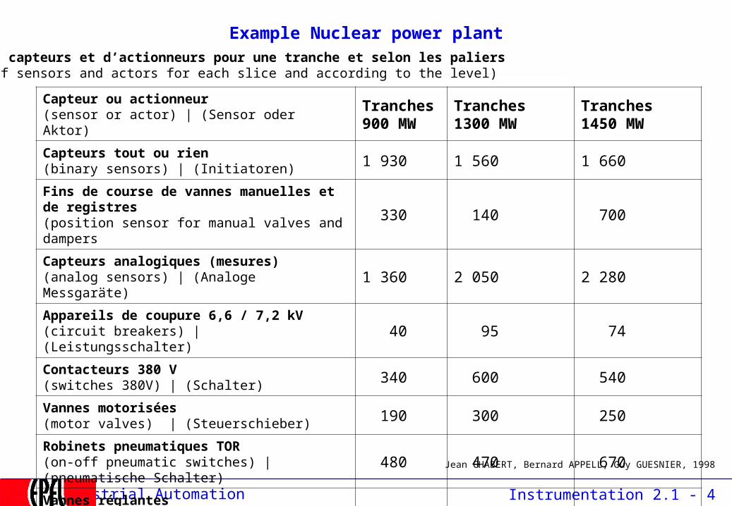
Example Nuclear power plantNombre de capteurs et d’actionneurs pour une tranche et selon les paliers(number of sensors and actors for each slice and according to the level)
Capteur ou actionneur (sensor or actor) | (Sensor oder Aktor)
Tranches 900 MW
Tranches1300 MW
Tranches1450 MW
Capteurs tout ou rien(binary sensors) | (Initiatoren) 1 930 1 560 1 660
Fins de course de vannes manuelles et de registres(position sensor for manual valves and dampers 330 140 700
Capteurs analogiques (mesures)(analog sensors) | (Analoge Messgaräte) 1 360 2 050 2 280
Appareils de coupure 6,6 / 7,2 kV(circuit breakers) | (Leistungsschalter) 40 95 74
Contacteurs 380 V(switches 380V) | (Schalter) 340 600 540
Vannes motorisées(motor valves) | (Steuerschieber) 190 300 250
Robinets pneumatiques TOR(on-off pneumatic switches) | (pneumatische Schalter) 480 470 670
Vannes réglantes(proportional valves) | ( Regelschieber) 180 500 110
Jean CHABERT, Bernard APPELL, Guy GUESNIER, 1998

Instrumentation 2.1 - 5Industrial Automation
Concepts
instruments = sensors (capteurs, Messgeber) and actors (actionneurs, Stellglieder)
binary (on/off) and analog (continuous) instruments are distinguished.
industrial conditions:
• temperature range commercial: (0°C to +70°C)industry (-40°C..+85°C)extended industrial(–40°C..+125°C)
• mechanical resilience (shocks and vibrations) EN 60068• protection: Electro-Magnetic (EM)-disturbances EN 55022, EN55024)• protection: water and moisture (IP67=completely sealed, IP20 = normal)• protection: NEMP (Nuclear EM Pulse) - water distribution, civil protection• mounting and replacement• robust connectors• power: DC mostly 24V= because of battery back-up, sometimes 48V=)

Instrumentation 2.1 - 6Industrial Automation
2.1.2 Binary Instruments
2.1 Instrumentation2.1.1 Market2.1.2 Binary instruments2.1.3 Analog Instruments2.1.4 Actors2.1.5 Transducers2.1.6 Instrumentation diagrams2.1.7 Protection classes
2.2 Control2.3 Programmable Logic Controllers
Instrumentation 2.1 - 7Industrial Automation
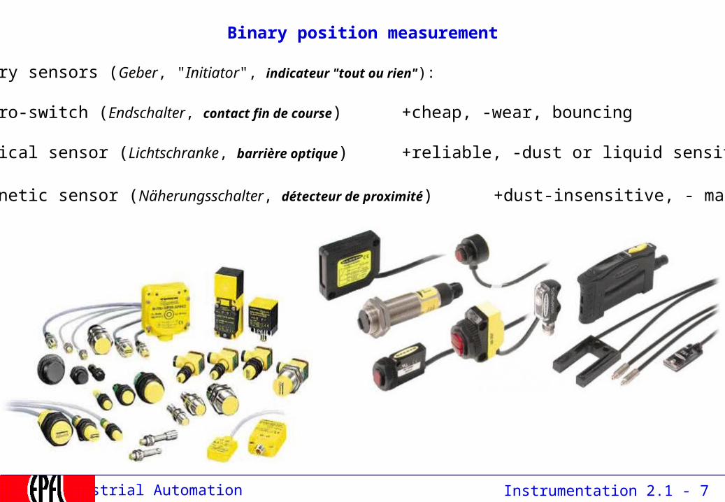
Binary position measurement
binary sensors (Geber, "Initiator", indicateur "tout ou rien"):
•micro-switch (Endschalter, contact fin de course) +cheap, -wear, bouncing
•optical sensor (Lichtschranke, barrière optique) +reliable, -dust or liquid sensitive
•magnetic sensor (Näherungsschalter, détecteur de proximité) +dust-insensitive, - magnetic

Instrumentation 2.1 - 8Industrial Automation
Binary Signal processing
Physical attachmentLevel adaptation,Galvanical separationEMC barrier (against sparks, radio, disturbances)
AcquisitionConvert to standard levelsRelay contacts 24V (most frequent), 48V, 110V (electrical substations) Electronic signals 24V —>10V-60V,Output: 0..24V@100mACounter inputs: Gray, BCD or binary
ProcessingFiltering (e.g. 0..8 ms filter),Plausibility (Antivalenz, Antivalence),Bounce-free (Entprellen, Anti-rebond)

Instrumentation 2.1 - 9Industrial Automation
2.1.3 Analog Instruments
2.1 Instrumentation2.1.1 Market2.1.2 Binary instruments2.1.3 Analog Instruments
2.1.3.1 Position and speed2.1.3.2 Temperature2.1.3.3 Hydraulic
2.1.4 Actors2.1.5 Transducers2.1.6 Instrumentation diagrams2.1.7 Protection classes
2.2 Control2.3 Programmable Logic Controllers

Instrumentation 2.1 - 10Industrial Automation
Precision (repeatability) and accuracy (deviation)
Not preciseNot accurate
Not preciseAccurate
PreciseNot accurate
PreciseAccurate
Accuracy is a consequence of systematic errors (or bad calibration) accuracy and precision may depends on time (drift)

Instrumentation 2.1 - 11Industrial Automation
Resolution and accuracy
• Resolution expresses how many different levels can be distinguished
• It is not related to accuracy

Instrumentation 2.1 - 12Industrial Automation
2.1.3.1 Analog mechanical position
potentiometercapacitivebalanced transformer (LVDT)
(linear or sin/cos encoder)strain gaugespiezo-electric
+cheap, -wear, bad resolution+cheap, -bad resolution+reliable, robust - small displacements
+reliable, very small displacements+extremely small displacements

Instrumentation 2.1 - 13Industrial Automation
Variable differential transformer (LVTD)
The LVDT is a variable-reluctance device, where a primary center coil establishes a magnetic flux that is coupled through a mobile armature to a symmetrically-wound secondary coil on either side of the primary. Two components comprise the LVDT: the mobile armature and the outer transformer windings. The secondary coils are series-opposed; wound in series but in opposite directions.
source: www.sensorland.com
When the moving armature is centered between the two series-opposed secondaries, equal magnetic flux couples into both secondaries; the voltage induced in one half of the secondary winding is 180 degrees out-of-phase with the voltage induced in the other half of the secondary winding. When the armature is moved out of that position, a voltage proportional to the displacement appears

Instrumentation 2.1 - 14Industrial Automation
Capacitive angle or position measurement
C = εA
d≈
fixed
movable
capacitance is evaluated by modifying the frequency of an oscillator

Instrumentation 2.1 - 15Industrial Automation
Small position measurement: strain gauges
R
A
2
V
A
volume = constant, = constant"
temperature compensation by “dummy” gauges
frequently used in buildings, bridges,dams for detecting movements.
Principle: the resistance of a wire with resistivity ρ increases when this wire is stretched:
'
Dehnungsmessstreifen (DMS), jauges de contrainte
≈ 2
UUo
R1
measure
R2
compensationR4
R3
measurement in bridge(if U0 = 0: R1R4 = R2R3)
ρ = resistivity

Instrumentation 2.1 - 16Industrial Automation
Piezo-electrical effect
source: Kistler
Piezoelectric materials (crystals) change form when an electrical field is applied to them.Conversely, piezoelectric materials produce an electrical field when deformed.
Quartz transducers exhibit remarkable properties that justify their large scale use in research, development, production and testing. They are extremely stable, rugged and compact.
Of the large number of piezoelectric materials available today, quartz is employed preferentially in transducer designs because of the following excellent properties:
• high material stress limit, around 100 MPa (~ 14 km water depth)
• temperature resistance (up to 500C)
• very high rigidity, high linearity and negligible hysteresis
• almost constant sensitivity over a wide temperature range
• ultra high insulation resistance (10+14 ohms) allowing low frequency measurements (<1 Hz)
Instrumentation 2.1 - 17Industrial Automation
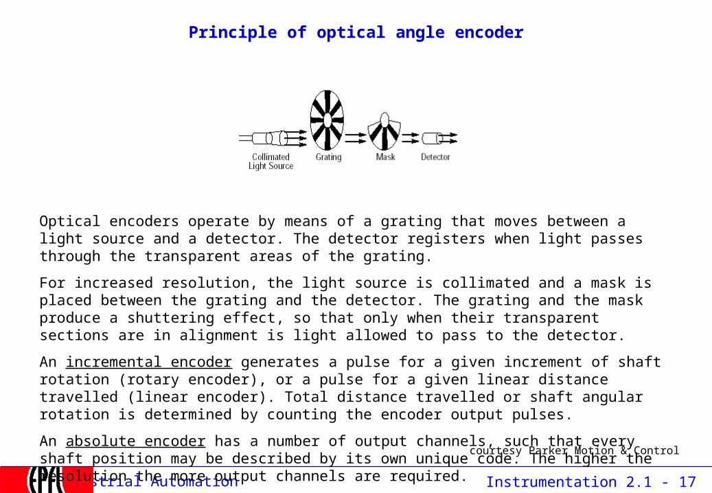
Principle of optical angle encoder
courtesy Parker Motion & Control
Optical encoders operate by means of a grating that moves between a light source and a detector. The detector registers when light passes through the transparent areas of the grating.
For increased resolution, the light source is collimated and a mask is placed between the grating and the detector. The grating and the mask produce a shuttering effect, so that only when their transparent sections are in alignment is light allowed to pass to the detector.
An incremental encoder generates a pulse for a given increment of shaft rotation (rotary encoder), or a pulse for a given linear distance travelled (linear encoder). Total distance travelled or shaft angular rotation is determined by counting the encoder output pulses.
An absolute encoder has a number of output channels, such that every shaft position may be described by its own unique code. The higher the resolution the more output channels are required.

Instrumentation 2.1 - 18Industrial Automation
Incremental angle encoder
Photo: Baumer
open mounted
Photo: Lenord & Bauer

Instrumentation 2.1 - 19Industrial Automation
courtesy Parker Motion & Control
Absolute digital position: Gray encoder
1 2 3 4 5 6 7 8 9 10 11 12 13 140 15
1 2 3 4 5 6 7 8 9 10 11 12 13 140 15
LSB
MSB
LSB
MSB
binary code: if all bits were to change at about the same time: glitches
Gray code: only one bit changes at a time: no glitch
Gray disk (8 bit)
00000001001000110100010101100111…
00000001001100100110011101010100
Instrumentation 2.1 - 20Industrial Automation
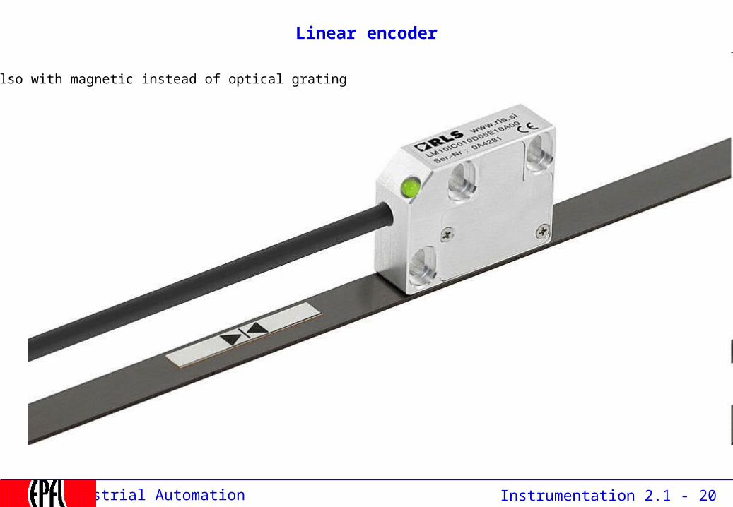
Linear encoder
Also with magnetic instead of optical grating

Instrumentation 2.1 - 21Industrial Automation
Force measurement
Force / Torque / Weight / Pressure is measured by small displacements (F = k • x):
- piezo-electrical transducers- strain gauges
Acceleration is measured by way of force / displacement measurement (F = M • )

Instrumentation 2.1 - 22Industrial Automation
Analog speed measurement: tachometer
angular speed
Ui ~ d / dt, f ~
transduceranalog: 4..20 mA
digital: 010110110
N
S
a simple tachometer is a rotating permanent magnet that induces a voltage into a stator winding.
this voltage is converted into an analog voltage or current, later converted to a digital value,
alternatively, the frequency of the signal can be measured to yield directly a digital value
Instrumentation 2.1 - 23Industrial Automation
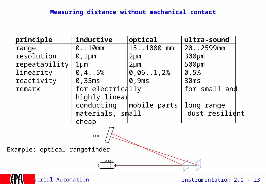
Measuring distance without mechanical contact
principle inductive optical ultra-soundrange 0..10mm 15..1000 mm 20..2599mmresolution 0,1µm 2µm 300µmrepeatability 1µm 2µm 500µmlinearity 0,4..5% 0,06..1,2% 0,5%reactivity 0,35ms 0,9ms 30msremark for electrically for small and highly linear
conducting mobile parts long rangematerials, small dust resilient
cheap
laser
CCD
Example: optical rangefinder

Instrumentation 2.1 - 24Industrial Automation
2.1.3.2 Temperature measurement
the most frequently measured value in industry
www.omega.com
Thermowell
Extension Assemblies
Protection and head assembly

Instrumentation 2.1 - 25Industrial Automation
Temperature measurement
Spectrometer: measures infrared radiation by photo-sensitive semiconductors+ highest temperature, measures surfaces, no contact- highest price
Thermistance (RTD - resistance temperature detector): metal whose resistance depends on temperature:
+ cheap, robust, high temperature range ( -180ºC ..600ºC), - require current source, non-linear.
Thermistor (NTC - negative temperature coefficient): semiconductor whose resistance depends on temperature: + very cheap, sensible, - low temperature, imprecise, needs current source, strongly non-linear, fragile, self-heating
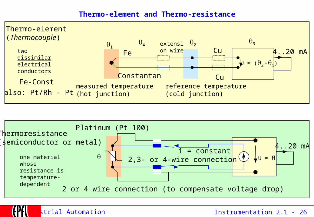
Thermo-element (Thermoelement, thermocouple): pair of dissimilar metals that generate a voltage proportional to the
temperature difference between warm and cold junction (Seebeck effect)+ high precision, high temperature, punctual measurement- low voltage, requires cold junction compensation, high amplification, linearization
Bimetal (Bimetall, bilame): mechanical (yes/no) temperature indicator using the difference in the dilatation coefficients of two metals, very cheap, widely used (toasters...)
Instrumentation 2.1 - 26Industrial Automation
Thermo-element and Thermo-resistance
Thermo-element(Thermocouple)
Thermoresistance(semiconductor or metal)
Platinum (Pt 100)
Fe-Const
also: Pt/Rh - Pt
21
Fe
Constantan
Cu
Cu
U ≈ (2-1)
U ≈ i = constant
34
2 or 4 wire connection (to compensate voltage drop)
2,3- or 4-wire connection
reference temperature(cold junction)
4..20 mA
4..20 mA
measured temperature(hot junction)
two dissimilar electrical conductors
one material whose resistance is temperature-dependent
extension wire

Instrumentation 2.1 - 27Industrial Automation
Cold junction box

Instrumentation 2.1 - 28Industrial Automation
2.1.3.3 Hydraulic measurements
•Flow,•Mass Flow, •Level, •Pressure,•Conductivity,•pH-Sensor,•Viscosity,•Humidity,
special requirements: intrinsic safety = explosive environment, sea floor = high pressure

Instrumentation 2.1 - 29Industrial Automation
Level measurement
•pulsed laser
•load cell
•pulsed microwave
•nuclear
•ultrasonic (40-60 kHz)
•low power ultrasonic
detectorrow
see Control Engineering, Aug 2003
F = mg

Instrumentation 2.1 - 30Industrial Automation
Flow measurement
Distinguish: volumetric flow ( m3/s)mass flow: (kg / s)identical when the density of the liquid is constant
main methods:-floater-turbine-pressure difference-vortex-temperature gradient-ultrasonic-electrodynamics

Instrumentation 2.1 - 31Industrial Automation
Flow velocity measurement: differential pressure (2 methods)
occultation(Verengung)
membrane
the flow velocity is proportional to the square root of the pressure difference
piezo-electricsensor
p2 - p1 = v21
2(Bernoulli effect)
p2 p1
v
fluid of viscosity
21
occultation(Blende)

Instrumentation 2.1 - 32Industrial Automation
Flow measurement
Other means:
Magnetic-dynamicCoriolisUltra-sound

Instrumentation 2.1 - 33Industrial Automation
Flow measurement in a plant

Instrumentation 2.1 - 34Industrial Automation
2.1.4 Actors
2.1 Instrumentation2.1.1 Market2.1.2 Binary instruments2.1.3 Analog Instruments2.1.4 Actors2.1.5 Transducers2.1.6 Instrumentation diagrams2.1.7 Protection classes
2.2 Control2.3 Programmable Logic Controllers

Instrumentation 2.1 - 35Industrial Automation
Actors (Actuators)
About 10% of the field elements are actors (that influence the process).Actors can be binary (on/off) or analog (e.g. variable speed drive)
The most common are:- electric contactors (relays)- heating elements- pneumatic and hydraulic movers (valve, pump) - electric motors (rotating and linear)
Actors are controlled by the same electrical signal levels as sensors use(4..20mA, 0..10V, 0..24V, etc.) but at higher power levels, e.g. to directly move a contactor (disjoncteur).
Stellantriebe, Servomoteurs

Instrumentation 2.1 - 36Industrial Automation
Electric Motors
Solenoids,DC motorAsynchronous Motors (Induction)Synchronous motorsStep motors, reluctance motors

Instrumentation 2.1 - 37Industrial Automation
Drives (variateurs de vitesse, Stellantriebe)
Variable speed drives control speed and acceleration and protect the motor(over-current, torque, temperature). High-power drives can feed back energy to the grid when braking (inverters). Drives is an own market (“Automation & Drives”)
simple motor control cabinet for power of > 10 kW small drive control < 10 kW(Rockwell)
Motors and drives are separate businesses
Instrumentation 2.1 - 38Industrial Automation
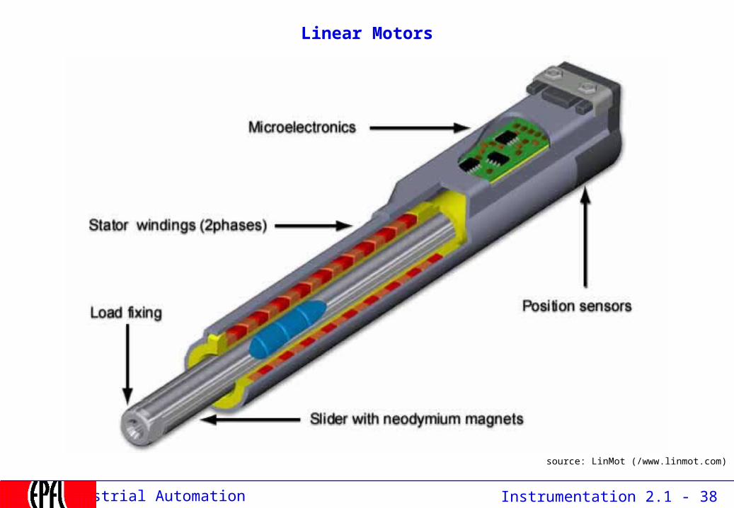
Linear Motors
source: LinMot (/www.linmot.com)

Instrumentation 2.1 - 39Industrial Automation
Hydraulics and fluidics…
Pumps, valves, rods,…
source: www.bachofen.ch
fluidic switches
switchboard ("Ventilinsel")
the most widespread actor in industry(lightweight, reliable, cheap)
I/P or E/P = electro-pneumatic transducers

Instrumentation 2.1 - 40Industrial Automation
2.1.5 Transducers
2.1 Instrumentation2.1.1 Market2.1.2 Binary instruments2.1.3 Analog Instruments2.1.4 Actors2.1.5 Transducers2.1.6 Instrumentation diagrams2.1.7 Protection classes
2.2 Control2.3 Programmable Logic Controllers

Instrumentation 2.1 - 41Industrial Automation
Transducer
A transducer converts the information supplied by a sensor (piezo, resistance,…)into a standardized signal which can be processed digitally.
Some transducers have directly a digital (field bus) output and are integratedin the sensor.
Other are located at distances of several meters from the sensor.

Instrumentation 2.1 - 42Industrial Automation
Example of analog transducer
Emergency panel
PLCControl Room
CurrentTransformer
0..1A rms
Field house
Transducer
4..20 mA R = Load
High voltage
Protection

Instrumentation 2.1 - 43Industrial Automation
4-20 mA loop standard
The transducer acts as a current source which delivers a current between 4 and 20 mA, proportional to the measurand (Messgrösse, valeur mesurée).
Information is conveyed by a current, the voltage drop along the cable induces no error.
0 mA signals an error (wire disconnection)
The number of loads connected in series is limited by the operating voltage (10..24 V).e.g. if (R1 + R2+ R3) = 1.5 ki = 24 / 1.5 = 16 mA, which is < 20 mA: NOT o.k.)
Simple devices are powered directly by the residual current (4mA) allowing to transmit signal and power through a single pair of wires.
Transducer instrument
1
instrument
2
instrument
3
0, 4..20 mA
R1 R2 R3
Object
i = f(v)
10..24V
voltage source
measurand
Instrumentation 2.1 - 44Industrial Automation
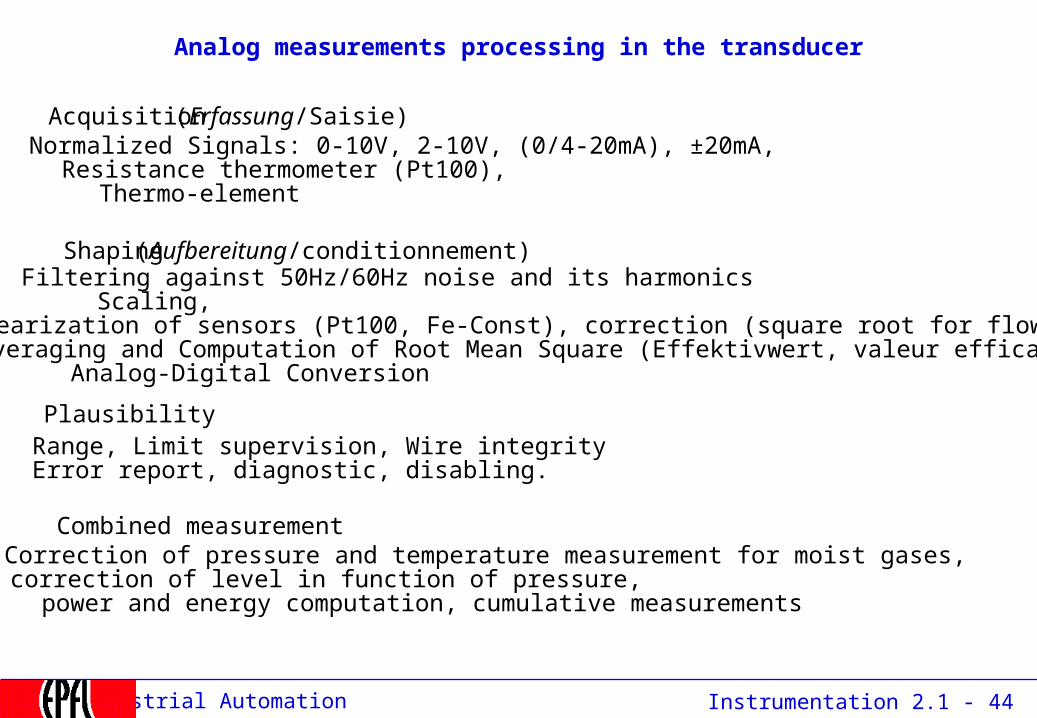
Analog measurements processing in the transducer
Acquisition (Erfassung/Saisie)
Correction of pressure and temperature measurement for moist gases,correction of level in function of pressure, power and energy computation, cumulative measurements
Range, Limit supervision, Wire integrityError report, diagnostic, disabling.
Combined measurement
Plausibility
Filtering against 50Hz/60Hz noise and its harmonicsScaling,Linearization of sensors (Pt100, Fe-Const), correction (square root for flow).Averaging and Computation of Root Mean Square (Effektivwert, valeur efficace),Analog-Digital Conversion
Shaping (Aufbereitung/conditionnement)
Normalized Signals: 0-10V, 2-10V, (0/4-20mA), ±20mA, Resistance thermometer (Pt100), Thermo-element
Instrumentation 2.1 - 45Industrial Automation
2.1.6 Instrumentation diagrams: P&ID
2.1 Instrumentation2.1.1 Market2.1.2 Binary instruments2.1.3 Analog Instruments2.1.4 Actors2.1.5 Transducers2.1.6 Instrumentation diagrams2.1.7 Protection classes
2.2 Control2.3 Programmable Logic Controllers

Instrumentation 2.1 - 46Industrial Automation
Instrumentation Diagrams
Similarly to electrical schemas, the control industry (especially the chemical and process industry) describes its plants and their instrumentation by a
P&ID (pronounce P.N.I.D.) (Piping aNd Instrumentation Diagram),sometimes called P&WD (Piping and wiring diagrams)
The P&ID shows the flows in a plant (in the chemical or process industry) and the corresponding sensors or actors.
At the same time, the P&ID gives a name ("tag") to each sensor and actor, along with additional parameters.
This tag identifies a "point" not only on the screens and controllers, but also on theobjects in the field.

Instrumentation 2.1 - 47Industrial Automation
P&ID example
4, Combustor C2
2, Air Heater C1
3, SOFC Outlet
3, SOFC Inlet
TA51BTI
TETETEPT
TA51ATI
TA51CTI
Chimney
EmissionAnalysis
PT22PI
TA22BTI
TE TE TE PT
TA22ATI
TA22CTI
Process Air Exhaust
Blow Off Valve
BE
10 xTE
TC2M1 - M10TI
FLAMDETC2BS
IngnitorBox
BE
10 xTE
TC1M1 - M10TI
Fuel Supply
SSVGAS3
IC
Atmosphere
PT21PI
TA21BTI
TE TE TE PT
TA21ATI
TA21CTI
Rotary block valve
V52IC
TETA62
TI
7, Heatexchanger
6, Recuperator
TE
LatchableCheck Valve
S
SVGAS2IC
FLAMDETC1BS
TA32BTI
TE TE TE
TA32CTI
TA32ATI
PT32PI
PT
TYI
P
Regulator Valve
TYI
P
SVGAS1IC
S
S
EMICOE
EMIUHCE
EMICO2E
EMIO2E
EMINOXE
AIT
AIT
AIT
AIT
AIT
PT51PI
Fro
m s
ampl
e pr
obe
atC
1 ex
it
TBVCOOLIC
TBVDEPIC
PT
TE
PT12PI
TA12TI
IGNITC2IC
TW72TI
PTPT52
PI
TETA52
TI
G
AC Grid
ModulatableLoad
PCS1,C
5,T
LOPPI
SPEEDSI
PTST
0, A
ir In
let
PT
TE
PT02PI
TA02TI
SV12IC
R
IngnitorBox C1
IGNITC1IC
Piping and Instrumentation Diagram for MTG100FC Engine Tests
S
VPPWMC2IC
FO
VMPWMC2IC
S
S
VMPWMC1IC
S
S
S
VPPWMC1IC
FO
Fuel flow C2 MFM
Fuel flow C1 MFM

Instrumentation 2.1 - 48Industrial Automation
P&ID
The P&ID mixes pneumatic / hydraulic elements, electrical elements and instruments on the same diagram
It uses a set of symbols defined in the ISA S5.1 standard.
Examples of pneumatic / hydraulic symbols:
pipe
valve
binary (or solenoid) valve (on/off)
350 kW heater
vessel / reactor
pump, also
heat exchangeranalog valve (continuous)
one-way valve (“diode”)

Instrumentation 2.1 - 49Industrial Automation
Instrumentation identification
V1528
FIC
S
tag name of the corresponding
variablehere: V1528
function (here: valve)
mover(here: solenoid)
The first letter defines the measured or initiating variables such as Analysis (A), Flow (F), Temperature (T), etc. with succeeding letters defining readout, passive, or output functions such as Indicator (I), Record (R), Transmit (T), see next slides, here: flow indicator digital

Instrumentation 2.1 - 50Industrial Automation
ISA S5.1 General instrument or function symbols
Primary location
accessible to operator
Field mountedAuxiliary location
accessible to operator
Discrete instruments
Shared display, shared control
Computer function
Programmable logic control
1. Symbol size may vary according to the user's needs and the type of document.2. Abbreviations of the user's choice may be used when necessary to specify location.3. Inaccessible (behind the panel) devices may be depicted using the same symbol but with a dashed horizontal bar.Source: Control Engineering with data from ISA S5.1 standard

Instrumentation 2.1 - 51Industrial Automation
Example of P&ID
FT101 is a field-mounted flow transmitter connected via electrical signals (dotted line) to flow indicating controller FIC 101 located in a shared control/display device
Square root extraction of the input signal is part of FIC 101’s functionality.
The output of FIC 101 is an electrical signal to TY 101located in an inaccessible or behind-the-panel-board location.
The output signal from TY 101 is a pneumatic signal (line with double forward slash marks) making TY 101 an I/P (current to pneumatic transducer)
TT 101 and TIC 101 are similar to FT 101 and FIC 101 but are measuring, indicating, and controlling temperature
TIC 101’s output is connected via an internal software or data link (line with bubbles) to the setpoint (SP) of FIC 101 to form a cascade control strategy

Instrumentation 2.1 - 52Industrial Automation
The ISA code for instrument type
First letter
Measured or initiating variable Modifier
A Analysis
B Burner, combustion
C User's choice
D User's choice DifferentialE Voltage
F Flow rate Ration (fraction)G User's choice
H Hand
I Current (electrical)
J Power ScanK Time, time schedule Time rate of changeL Level
M User's choice MomentaryN User's choice
O User's choice
P Pressure, vacuum
Q Quantity Integrate, totalizerR Radiation
S Speed, frequency SafetyT Temperature
U Multivariable
V Vibration, mechanical analysis
W Weight, force
X Unclassified X axisY Event, state, or presence Y axisZ Position, dimension Z axis

Instrumentation 2.1 - 53Industrial Automation
Common connecting lines
Connection to process, or instrument supply
Pneumatic signal
Electric signal
Capillary tubing (filled system)
Hydraulic signal
Electromagnetic or sonic signal (guided)Internal system link (software or data link)Source: Control Engineering with data from ISA S5.1 standard

Instrumentation 2.1 - 54Industrial Automation
P&ID in computer readable form: IEC 62424
1
2
3
connections between objects
auxiliary signals
location categories
role
CAEX component library

Instrumentation 2.1 - 55Industrial Automation
2.1.7 Protection Classes
2.1 Instrumentation2.1.1 Market2.1.2 Binary instruments2.1.3 Analog Instruments2.1.4 Actors2.1.5 Transducers2.1.6 Instrumentation diagrams2.1.7 Protection classes
2.2 Control2.3 Programmable Logic Controllers
Instrumentation 2.1 - 56Industrial Automation
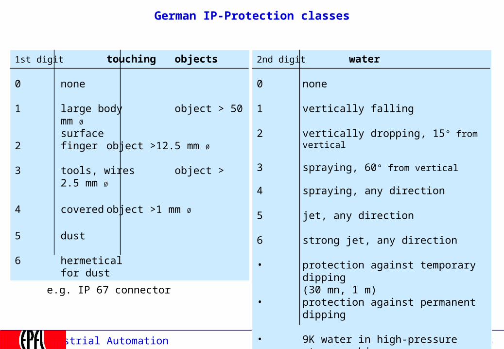
German IP-Protection classes
2nd digit water
0 none
1 vertically falling
2 vertically dropping, 15° from vertical
3 spraying, 60° from vertical
4 spraying, any direction
5 jet, any direction
6 strong jet, any direction
• protection against temporary dipping(30 mn, 1 m)
• protection against permanent dipping
• 9K water in high-pressure steam washing
1st digit touching objects
0 none
1 large body object > 50 mm Øsurface
2 finger object >12.5 mm Ø
3 tools, wires object > 2.5 mm Ø
4 covered object >1 mm Ø
5 dust
6 hermeticalfor dust
e.g. IP 67 connector

Instrumentation 2.1 - 57Industrial Automation
Explosion protection
Instruments that operate in explosive environments (e.g. petrochemical, pharmaceutical, coal mines,...) are subject to particular restrictions.
e.g. They may not contain anything that can produce sparks or high heat, such as electrolytic capacitors or batteries without current limitation.Their design or programming may not be altered after their acceptance. Their price is higher than that of standard devices because they have to undergo strict testing (Typentest, type test) by a qualified authority (TÜV in Germany)
Such devices are called Eex - or "intrinsic safety devices" (Eigensichere Geräte, "Ex-Schutz", protection anti-déflagrante, "Ex" ) and are identified by the following logo:

Instrumentation 2.1 - 58Industrial Automation
European Explosion-Proof Code
Eex-devices are "safe" (certified) to be used in an explosive environment. They must have passed a type test at TÜF (Germany), UL (USA),...
Swiss Norm: "Verordnung über Geräte und Schutzsysteme in explosionsgefährdeten Bereichen"

Instrumentation 2.1 - 59Industrial Automation
Field Device: faceplate (movie)

Instrumentation 2.1 - 60Industrial Automation
Assessment
How are binary process variables measured ?
How are analogue process variables measured ?
How is temperature measured ?
What is the difference between a thermocouple and a thermoresistance ?
How is position measured (analog and digital) ?
What is a Gray encoder ?
How is speed measured ?
How is force measured ?
What is a P&ID ?
What is a transducer ?
How does a 4..20 mA loop operate ?