Embed Size (px)
Citation preview

.—.
●
Chapter 2
Ceramics
.

. . , .
, - .
* . .
. .
. . .
, CONTENTS
Page fFindings . ● . , ● . ● . ● . . . . ● . , . . , . . 3 7 2-3. Projected U.S. Markets for Structural
> * * * * * . * . * * * * * . * * * . . . . . . . * . * . * 38 Ceramics in the Year 2000 . . . . . . . . . . . . .. . . . . . . . . . . . . . . . . . 38 2-4. Load-Deflection Curve for a Nicalon Fiber-Ceramic Matrix Composites ●☛ ● ● .., . . . ● 4 0 Reinforced Silicon Nitride Composite. . . . .
Ceramic Coatings . ● . ● . . . . ● . . . ● .,. ● . . . . . 4?Tables . . . . . . . . . . . . . . . . . . . . 42“
2-1. Some Future Applications of StructuralCeramics . . . . . . . . . . . . . . . . . . . . . . . . . . ...?, . . . . . . . . . . . . . . . 2-2. Comparison of Physical and MechanicalProperties of Common Structural Ceramics . . ● ● . . . . , . . .with Steel and Aluminum Alloys . . . . . . .
● ● * ’ * . * * . . . . , ● , ● . .l Ceramics . . . . . . . . . . 50 2-3. Fracture Toughness and Critical Flaw
, Size of Monolithic and Composite Ceramic* * * . * * * * * * * ...**.... 50s.. . . . . . . . . . ● . . . . . . 52 Materials Compared with Metals . . . . . . .
Far-Term Applications....,,,...,.,... .., 5 2 2-4 Common Processing Operations for
, *need Stuctural Advanced Ceramics . . . . . . . . . . . . . . . . . .2-5. Selected Processes for the Production of- - -%. .., ,+ ..,..,6,”,.....,,...,,. 52
,::; , Ceramic Coatings and for the Modification~ ns and Production . . . . . . . 64: : ● ‘ . . . . ● “ , ● .. ..+, . 64 of Ceramic Surfaces. . . . . . . . . . . . . . . . . .
compodtw . . . ● . ● . . . . ● * . . 64 2-6. Characteristics and Properties of Ceramic
‘j; I%& @r Ceramics ....., . . . . . . . . 6!5 Coatings Often Considered Desirable. . . .
65 2-7. Comparison of the Mechanical Properties. . . . * . * * . * . .,, . . . . . . . . . . .I%04Wion of Various Cements and Aluminum . . . . ., ‘ .;+ . * * * * . ., * . . . . .***,*... 66
‘“.i~amh’md 04weloprmmt Priorities . . . . . . . . 66 2-8. Comparison of Some Possible Production-
;; VW knpottant. . . . . . : . . . . . e . . . . . . . . . . . . 67 Level NDE Techniques for Structural7-
‘ ~ wnpO&Rt ● 68 Ceramics. . . . . . . . . . . . . . . . . . . . . . . . . . .* * . ., . ., + * . . . . . .,, * .,, ***..*.w .,, H* . . . . . . . . . . . . . . . . . . . . . . . . . . . . . 69 2-9. Future Diesel Engine Technology
. Development Scenario . . . . . . . . . . . . . . .
.,. ,.. .’2-10. Structural Ceramic Technology: Federal‘ , -. ‘. . . Figures Government Funded R&D. . . . . . . . . . . . .
F i g u r e N o . Page 2-11. Breakout of the Fiscal Year 1985 Structural. .2-1. ~--Faikm? of a Ceramic Ceramics Budget According to the R&D “ .*** **6 * S , ” ”,, . . . . . . . . . . . . 40 Priorities Cited in the Text . . . . . . . . . . . .
2-2. 2-Z for of
C e r a m i c C o m p o n e n t s in Structural. Application Categories . . ● . ● . . . ● . ● 51
. ._.” .
.
.
- . .
.’ .
‘age
53
65
Page
38
39
41
43
46,
47
48
50
60
67
70

Chapter 2
Ceramics
FINDINGS
The broad class of materials known as ceram-ics includes all solids that are neither metallic nororganic. Advanced structural ceramics differ fromconventional ceramic consumer goods in thatthey are made from extremely pure, microscopicpowders that are consolidated at high tempera-tures to yield a dense, durable structure. Com-pared with metals, advanced structural ceramicshave superior wear resistance, high-temperaturestrength, and chemical stability. They generallyhave lower electrical and thermal conductivity,and lower toughness. The low toughness of ce-ramics (brittleness) causes them to fail suddenlywhen the applied stress is sufficient to propagatecracks that originate at flaws in the material. Theactual stress level at which this occurs can be veryhigh if the flaw sizes are small. However, unpre-dictable failure caused by poor control over flawpopulations remains a major handicap to the useof structural ceramics in load-bearing applications.
There are several methods that can reduce thesensitivity of ceramics to flaws. Incorporation ofceramic particulate, whiskers, or continuousfibers in a ceramic matrix can produce a com-posite that absorbs more energy during fracturethan the matrix alone, and is therefore tougher.A different approach is the application of a thinceramic coating to a metal substrate. This yieldsa component with the surface properties of a ce-ramic combined with the high toughness of metalin the bulk.
Advanced ceramic components are more ex-pensive than the metal components they wouldreplace. This is primarily due to the high cost ofprocesses that are capable of fabricating ceram-ics reliably and reproducibly. Finishing and machin-ing operations to form the part to its final shapeare expensive due to the extreme hardness of thetnaterial. Nondestructive testing to ensure relia-bility is also a major component of productioncosts. Therefore, development of processes thatcan reliably fabricate a component to final netshape is crucial, In many applications, thin coat-
ings of a high-performance ceramic on a metalsubstrate may offer the best compromise betweencost and performance.
Applications and MarketOpportunities
Advanced structural ceramics are in produc-tion for wear parts, cutting tools, bearings, filters,and coatings. Ceramics are also in limited pro-duction (in Japan) in discrete engine componentssuch as turbocharger rotors, glow plugs, and pre-combustion chambers. Current military applica-tions in the United States include radomes, ar-mor, and infrared windows.
Near-term production (next 10 to 15 years) isexpected in advanced bearings, bioceramics,construction applications, heat exchangers, elec-trochemical devices, discrete components in au-tomobile engines, and military engines. Especiallyhigh growth may be seen in bioceramics for den-tal and orthopedic implants, and chemicallybonded ceramics for construction applications.
Far-term applications (beyond 15 years) arethose that require solution of major technical andeconomic problems. These include an advancedautomotive turbine engine, an advanced ceramicdiesel (although ceramics could be used in mili-tary versions of these engines at an earlier date),some electrochemical devices, military compo-nents, and heat exchangers. A variety of otherturbine engines, especially turbines for aircraftpropulsion and for utility-scale power generation,should also be categorized as far-term.
Research and Development Priorities
The following hierarchy of R&D priorities isbased on the technical barriers that must be over-come before ceramics can be used in the appli-cations discussed above.
37

38 ● Advanced Materials by Design
Processing Science
This is the key to understanding how process-ing variables such as temperature, composition,and particle size distribution are connected to thedesired final properties of the ceramic.
Environmental Behavior
In many applications, ceramics are required towithstand high-temperature, corrosive, or erosiveenvironments. Information on the behavior of ce-ramics in these environments is essential to pre-dict the service life of ceramics in those appli-cations.
Reliability
The reliability of advanced ceramics and ce-ramic composites is the single most important de-terminant of success in any application. Progressrequires advances in design of brittle materials,process control, nondestructive evaluation, un-derstanding crack growth processes, and lifeprediction.
Ceramic Composites
These novel materials offer an exciting oppor-tunity to increase the strength and toughness ofceramics.
INTRODUCTION
Ceramics are nonmetallic, inorganic solids. Byfar the most common of terrestrial materials,ceramics made of sand and clay have been usedfor many thousands of years for brick, pottery,and artware. However, modern structural ceram-ics bear little resemblance to these traditional ma-terials; they are made from extremely pure,microscopic powders that are consolidated athigh temperatures to yield a dense and durablestructure.
The U.S. market for advanced structural ceram-ics in 1987 was $171 million. ’ In the next 10 to15 years, however, the market opportunities forstructural ceramics are expected to expand rap-idly (table 2-1 ) such that by the year 2000, theU.S. market alone is projected to be between $1billion and $5 billion per year.2
Properties of Ceramics
The properties of some common structural ce-ramics are compared with those of metals in ta-ble 2-2. In general, ceramics have superior high-temperature strength, higher hardness, lowerdensity, and lower thermal conductivity than me-tals. The principal disadvantage of using ceram-
‘Up from $112 million in 1985, according to data supplied byBusiness Communications Co., Inc. of Norwalk, CT. This includeswear parts, cutting tools, heat exchangers, engine components,bioceramics, and aerospace applications.
2Greg Fischer, “Strategies Emerge for Advanced Ceramic Busi-ness,” American Ceramic Society Bulletin 65(1):39, 1986.
ics as structural materials is the sensitivity of theirstrength to extremely small flaws, such as cracks,voids, and inclusions. Flaws as small as 10 to 50micrometers can reduce the strength of a ceramicstructure to a few percent of its theoreticalstrength. Because of their small sizes, the strength-controlling flaws are usually very difficult to de-tect and eliminate.
The flaw sensitivity of ceramics illustrates theimportance of carefully controlled processing andfinishing operations for ceramic components.However, even with the most painstaking efforts,a statistical distribution of flaws of various sizes
Table 2-1.—Some Future Applications ofStructural Ceramics
Application Performance advantages Examples
Wear partssealsbearingsvalvesnozzles
Cutting toolsHeat engines
diesel componentsgas turbines
Medical implantshipsteethjoints
Constructionhighwaysbridgesbuildings
High hardness, low friction
High strength, hot hardnessThermal insulation, high
temperature strength, fueleconomy
Biocompatibility, surfacebond to tissue, corrosionresistance
Improved durability, loweroverall cost
Silicon carbide,alumina
Silicon nitrideZirconia, silicon
carbide, sili-con nitride
Hydroxylapatite,bioglass,alumina,zirconia
Advanced ce-ments andconcretes
SOURCE Off Ice of Technology Assessment, 1988

Ch. 2—Ceramics “ 39
Table 2-2.—Comparison of Physical and Mechanical Properties of Common Structural Ceramics WithSteel and Aluminum Alloys. SiC: silicon carbide; Si3N4: silicon nitride; ZrO2: zirconia
Strength aThermal
Density a Room temperature at 1,095° C Hardness b conductivityMaterial (g/cm3) strength (MPa) (M Pa) (kg/mm2) 25°/1,100° (W/m° C)
Various sintered SiC materials . . . . 3.2 340-550 (flexure) 340-550 (flexure) 2,500-2,790 85/175Various sintered Si3N 4 materials . . 2.7-3.2 205-690 (flexure) 205-690 (flexure) 2,000C 17/60Transformation toughened ZrO2 . . . 5.8 500-1,250 (flexure)c — 1,300-1,635C 1.713.5Steels (4100, 4300, 8600, and
5600 series) . . . . . . . . . . . . . . . . . . 7-8 1,035-1,380 (tensile yield) useless 450-650 43Aluminum alloy . . . . . . . . . . . . . . . . . 2.5 415-895 (tensile yield) useless 100-500 140-225NOTE: 1 MPa = 145 psi = 0.102 Kg/mm2.SOURCES: aR. Nathan Katz, “Applications of High Performance Ceramics in Heat Engine Design,” Materials Science and Engineering 71:227-249, 1985.
bElalne P. Rothman, “Ultimate Properties of Ceramics and Ceramic Matrix Composites,”C"Ceramic Application and Design,”
contractor report for OTA, December 1985.Ceramic Industry, February 1988, pp. 29-50.
and locations will always exist in any ceramicstructure. Even identically prepared ceramic speci-mens will display a distribution of strengths, ratherthan a single value. Design with ceramics, un-like design with metals, is therefore a statisticalprocess, rather than a deterministic process.
Ceramic failure probability is illustrated in fig-ure 2-1. The curve on the right in figure 2-1a rep-resents the distribution of strengths in a batch ofidentically prepared ceramic components. Thecurve on the left is the distribution of stresses thatthese components are subjected to in service.The overlap between the two curves, in whichthe stress in service exceeds the strength of theceramic, determines the probability that the partwill fail.
There are several ways to reduce the probabil-ity of failure of the ceramic. One is to shift thestrength distribution curve to the right by elimi-nation of the larger flaws, as shown in figure 2-1 b. A second way is to use nondestructive testingor proof testing to weed out those componentswith major flaws. This leads to a truncation of thestrength distribution, as shown in figure 2-1c.Proof testing of each individual component, al-though widely used in the industry today, is ex-pensive and can introduce flaws in the materialthat were not there originally.
A third way to reduce failure probability is todesign the microstructure of the ceramic so thatit has some resistance to fracture (increased tough-ness), and hence, some tolerance to defects.Toughness is a measure of the energy requiredto fracture a material in the presence of flaws.For a ceramic component under stress, the tough-
ness determines the critical flaw size that will leadto catastrophic failure at that stress. In fact, thecritical flaw size increases with the square of thetoughness parameter; thus, an increase in the ma-terial toughness of a factor of three leads to aninefold increase in the flaw size tolerance.
Reduction in the flaw sensitivity of ceramics isespecially important for applications involving ahostile environment, which can introduce strength-degrading defects and thus negate all efforts toensure reliability by identifying or eliminating thelargest preexisting flaws.
Three recent developments have been shownto improve the toughness of ceramics: micro-structure design, transformation toughening, andcomposite reinforcement.
Microstructure Design
The toughness of monolithic ceramics can beimproved considerably by refinement of the poly-crystalline grain size and shape. The presence ofelongated fibrous grains, especially in ceramicsbased on silicon nitride, has been shown to in-crease toughness by as much as a factor of 2 overother monolithic ceramics, such as silicon car-bide and aluminum oxide.3
Numerous mechanisms have been proposedto account for the observed toughening: crackdeflection, microcracking, residual stresses, crackpinning, and crack bridging. It is likely that sev-eral of these mechanisms operate simultaneously
3Nitrogen Ceramics, F. L. Riley (cd. ) (Boston and The Hague: Mar-tinus Nijhoff Publishers, 1983).

40 . Advanced Materials by Design
in these materials. The high toughness is accom-panied by high strength, both of which resultfrom the modified microstructure.
Figure 2-1 .—Probabiiity of Faiiure ofa Ceramic Component
The probability of failure of a ceramic component is the over-lap between the applied stress distribution and the materialstrength distribution, as shown in(a). This probability can bereduced by reducing the flaw size (b), or truncation of thestrength distribution through proof testing (c).SOURCE: R. Nathan Katz “Applications of High Performance Ceramics In Heat
Engine Design,” Materials Science and Engineering 71:227-249, 1985.
Transformation Toughening
Transformation toughening, a relatively newapproach to achieving high toughness and strengthin ceramics, has great potential for increasing theuse of ceramics in wear-resistance applications.The key ceramic material is zirconia (zirconiumoxide).
Zirconia goes through a phase transformationfrom the tetragonal to the monoclinic crystal formwhile cooling through a temperature of about21 00° F (1 150° C). This phase transformation isaccompanied by an increase in volume of 3 per-cent, similar to the volume increase that occurswhen water freezes. By control of composition,particle size, and heat treatment cycle, zirconiacan be densified at high temperature and cooledsuch that the tetragonal phase is maintaineddown to room temperature.
When a load is applied to the zirconia and acrack starts to propagate, the high stresses in thevicinity of the crack tip catalyze the transforma-tion of adjacent tetragonal zirconia grains to themonoclinic form, causing them to expand by 3percent. This expansion of the grains around thecrack tip compresses the crack opening, therebypreventing the crack from propagating.
Ceramic Matrix Composites
A variety of ceramic particulate, whiskershigh-strength single crystals with length/diameter
ratios of 10 or more), and fibers may be addedto the host matrix material to generate a com-posite with improved fracture toughness.
The presence of these reinforcements appearsto frustrate the propagation of cracks by at leastthree mechanisms. First, when the crack tip en-counters a particle or fiber that it cannot easilybreak or get around, it is deflected off in anotherdirection. Thus, the crack is prevented frompropagating cleanly through the structure. Sec-ond, if the bond between the reinforcement andthe matrix is not too strong, crack propagationenergy can be absorbed by pullout of the fiberfrom its original location. Third, fibers can bridgea crack, holding the two faces together, and thusprevent further propagation.

Ch. 2—Ceramics ● 4 1
Table 2-3 presents the fracture toughness andcritical flaw sizes (assuming a typical stress of 700megapascals [MPa], or about 100,000 pounds persquare inch [psi]) of a variety of ceramics andcompares them with some common metals. Thetoughness of monolithic ceramics generally fallsin the range of 3 to 6 MPa-m½, correspondingto a critical flaw size of 18 to 74 micrometers.With transformation toughening or whisker dis-persion, the toughness can be increased to 8 to12 MPa-m½ (the critical flaw size is 131 to 294micrometers); the toughest ceramic matrix com-posites are continuous fiber-reinforced glasses,at 15 to 25 MPa-m½. In these glasses, strengthappears to be independent of preexisting flaw sizeand is thus an intrinsic material property. By com-parison, metal alloys such as steel have tough-nesses of more than 40 MPa-m½, more than 10
Table 2-3.—Fracture Toughness and Critical FlawSize of Monolithic and Composite Ceramic
Materials Compared With Metals.a
Al2O 3: alumina; LAS: lithium aluminosilicate;CVD: chemical vapor deposition
Fracturetoughness
Material (MPa•m½)
Conventional microstructure:Al 2 O 3 . . . . . . . . . . . . . . . . . . 3.5-4.0Sintered SiC. . . . . . . . . . . . 3.0-3.5
Fibrous or interlockedmicrostructure:
Hot pressed Si3N4 . . . . . . . 4.0-6.0Sintered Si3N 4 . . . . . . . . . . 4.0-6.0SiAION . . . . . . . . . . . . . . . . 4.0-6.0
Particulate dispersions:Al 2O3TiC . . . . . . . . . . . . . . 4.2-4.5Si3N4-TiC. . . . . . . . . . . . . . . 4.5
Transformation toughening:ZrO2-MgO . . . . . . . . . . . . . . 9-12ZrO 2-Y2O3 . . . . . . . . . . . . . . 6-9Al 2O3-ZrO 2 . . . . . . . . . . . . . 6.5-15
Whisker dispersions:Al2O3-SiC . . . . . . . . . . . . . . 8-10
Fiber reinforcement:b
SiC in borosilicate glass . 15-25SiC in LAS . . . . . . . . . . . . . 15-25SiC in CVD SiC . . . . . . . . . 8-15
Aluminum c . . . . . . . . . . . . . . . . . 33-44Steel c . . . . . . . . . . . . . . . . . . . . . 44-66
Criticalflaw size
(micrometers)
25-3318-25
33-7433-7433-74
36-4141
165-29474-16586-459
131-204
times the values of monolithic ceramics; the tough-ness of some alloys may be much higher.
The critical flaw size gives an indication of theminimum flaw size that must be reliably detectedin any nondestructive evaluation (N DE) to ensurereliability of the component. Most N DE techniquescannot reliably detect flaws smaller than about100 micrometers (corresponding to a toughnessof about 7 MPa-m½). Toughnesses of at least 10to 12 MPa-m½ would be desirable for most com-ponents.
Ceramic Coatings
The operation of machinery in hostile environ-ments (e. g., high temperatures, high mechanicalloads, or corrosive chemicals) often results in per-formance degradation due to excessive wear andfriction, and productivity losses due to shutdownscaused by component failure. Frequently, thecomponent deterioration can be traced to dele-terious processes occurring in the surface regionof the material. To reduce or eliminate such ef-fects, ceramic coatings have been developed toprotect or lubricate a variety of substrate materi-als, including metals, ceramics, and cermets(ceramic-metal composites).
The coating approach offers several advan-tages. First, it is possible to optimize independ-ently the properties of the surface region andthose of the base material for a given application.Second, it is possible to maintain close dimen-sional tolerances of the coated workpiece in thatvery thin coatings (of the order of a few micro-meters) are often sufficient for a given applica-tion. Third, there are significant cost savings asso-ciated with using expensive, exotic materials onlyfor thin coatings and not for bulk components.Use of coatings can thereby contribute to theconservation of strategically critical materials.Fourth, it is often cheaper to recoat a worn partthan to replace it.
aAssumes a stress of 700 MPa (-100,000 psi).bThe strength of these composites is independent of preexisting flaw size.cThe toughness of some alloys can be much higher
SOURCES: David W. Richerson, “Design, Processing Development, and Manufac-turing Requirements of Ceramics and Ceramic Matrix Composites,”contractor report for OTA December 1985; and Elaine P. Rothman,“Ultimate Properties of Ceramics and Ceramic Matrix Composites,”contractor report for OTA, December 1985
These advantages have led to widespread in-
dustry acceptance and applications. For instance,coatings of titanium nitride, titanium carbide, andalumina are used to extend the useful life of tung-sten carbide or high-speed steel cutting tools by

42 ● Advanced Materials by Design
a factor of 2 to 5,4 In 1983, annual sales of coatedcutting tools reached about $1 billions.5
Ceramic coatings are also finding wide appli-cation in heat engines. Zirconia coatings of lowthermal conductivity are being tested as a ther-mal barrier to protect the metal pistons andcylinders of advanced diesel engines. In turbineengines, insulative zirconia coatings have been
4 D a v i d W . R i c h e r s o n , “ D e s i g n , P r o c e s s i n g D e v e l o p m e n t , a n d
Manufacturing Requirements of Ceramics and Ceramic Matrix Com-
posites, ” contractor report prepared for the Office of Technology
Assessment , December 1985.
‘U.S. Department of Commerce, Bureau of the Census, C e n s u sof Manufacturing, Fuels, and Electric Energy Consumed, 1984.
found to improve performance by permittingcombustion gas temperatures to be increased byseveral hundred degrees Fahrenheit without in-creasing the temperature of air-cooled metalcomponents or the complexity of the engine.6 Ce-ramic coatings are also being used to provide anoxidation barrier on turbine blades and rings.
Progress in the use of ceramic coatings in theseand other applications suggest that further re-search on new coatings and deposition processesis likely to yield a high payoff in the future.
6Tom Strangman, Garrett Turbine Engine Co., personal c o m m u -
nication, August 1986.
DESIGN, PROCESSING, AND TESTING
It is in the nature of advanced structural mate-rials that their manufacturing processes are ad-ditive rather than subtractive. Ideally, the mate-rials are not produced in billets or sheets that arelater rolled, cut, or machined to their final shape;rather, in each case the material is formed to itsfinal shape in the same step in which the micro-structure of the material itself is formed.
Because of the severity of joining problems, theceramics designer is always conscious of the needto consolidate as many components as possibletogether in a single structure. Although consoli-dation cannot always be achieved (expensivegrinding or drilling is often required), to a greatextent, the promise of advanced materials lies inthe possibility of net-shape processing, thereby elim-inating expensive finishing and fastening oper-ations.
Ceramics Design
Designing with ceramics and other brittle ma-terials is very different from designing with me-tals, which are much more tolerant of flaws. Inpractice, ceramic structures always contain a dis-tribution of flaws, both on the surface and in thebulk. Ceramic designs must avoid local stress con-centrations under loading, which may propagatecracks originating at the flaws.
One serious barrier to the use of ceramics isthe lack of knowledge among designers of the
principles of brittle material design. Greater em-phasis needs to be placed on brittle materials incollege curricula. Courses at the college level andminicourses for continuing education on designfor brittle materials should be offered and pub-licized. 7
A second serious barrier is the poor characteri-zation of commercially available ceramics for de-sign purposes. The data are inadequate becausethe mechanical, thermal, and chemical proper-ties of ceramic materials vary with the methodof manufacture as well as the test method. Bothcarefully controlled and documented processingprocedures and standard test methods, as dis-cussed in chapter 5, will be required to givedesigners the confidence that consistent proper-ties at a useful level can be obtained at a predict-able cost.
Processing of Ceramics
The production of most ceramics, includingboth traditional and advanced ceramics, consistsof the following four basic process steps: pow-der preparation, forming, densification, and fin-ishing. The most important processing techniquesinvolved in these steps are identified in table 2-4.
7Specific proposals for improving ceramics education are givenin the report of the Research Briefing Panel on Ceramics and Ce-ramic Composites (Washington, DC: National Academy Press,1985).

Ch. 2—Ceramics “ 43
Table 2.4.—Common Processing Operations forAdvanced Ceramics
Operation Process Examples
Forming
Powderpreparation Synthesis SiC
Sizing Si3N4
Granulating Zr02
BlendingSolution chemistry GlassesSlip casting Combustors, statorsDry pressing Cutting toolsExtrusion Tubing, honeycombInjection molding Turbocharger rotorsTape casting CapacitorsMelting/casting Glass ceramics
Densification Sintering Al203
Reaction bonding Si3N4
Hot pressing Si3N4, SiC, BNHot isostatic pressing Si3N4, SiC
Finishing Mechanical Diamond grindingChemical EtchingRadiation Laser, electron beamElectric Electric discharge
SOURCE Office of Technology Assessment 1988
Powder Preparation
Although most of the basic raw materials forceramics occur abundantly in nature, they mustbe extensively refined or processed before theycan be used to fabricate structures. The entiregroup of silicon-based ceramics (other than sil-ica) does not occur naturally. Compositions ofsilicon carbide, silicon nitride, and sialon (an al-loy of silicon nitride with aluminum oxide inwhich aluminum and oxygen atoms substituteinto silicon and nitrogen lattice positions, respec-tively) must all be fabricated from gases or otheringredients. Even minerals that occur naturally,such as bauxite, from which alumina is made,and zircon sands, from which zirconia is derived,must be processed before use to control purity,particle size and distribution, and homogeneity.
The crucial importance of powder preparationhas been recognized in recent years. Particle sizesand size distributions are critical in advanced ce-ramics to produce uniform green (unfired) den-sities, so that consolidation can occur to producea fully dense, sintered, ceramic part.
Various dopants or sintering aids are added toceramic powders during processing. Sinterabil-ity can be enhanced with dopants, which con-trol particle rearrangement and diffusivities. Thesedopants permit sintering at lower temperatures
and/or faster rates. Dopants are also used to con-trol grain growth or achieve higher final densities.
The use of dopants, although providing manybeneficial results, can also have a detrimental in-fluence on the material properties. Segregationof dopants at the grain boundaries can weakenthe final part, and final properties such as con-ductivity and strength may differ significantly fromthose of the pure material.
Forming
Ceramic raw materials must be formed andshaped before firing. The forming process oftendetermines the final ceramic properties. The im-portant variables in the forming step are particleshape, particle packing and distribution, phasedistribution, and location of pores.
Forming processes for ceramics are generallyclassified as either cold forming or hot forming.The major cold forming processes include slipcasting, extrusion, dry pressing, injection mold-ing, tape casting, and variations of these. Theproduct of such processes is called a green body,which may be machined before firing. The homo-geneity of the cold-formed part determines theuniformity of shrinkage during firing.
Hot forming processes combine into one stepthe forming and sintering operation to producesimple geometric shapes. These processes includehot pressing (in which pressure is applied alongone direction) and hot isostatic pressing (HI Ping,i n which pressure is applied to the ceramic fromall directions at once).
Densification
Sintering is the primary method for convertingloosely bonded powder into a dense ceramicbody. Sintering involves consolidation of thepowder compact by diffusion on an atomic scale.Moisture and organics are first burned out fromthe green body, and then, at the temperaturerange at which the diffusion process occurs, mat-ter moves from the particles into the void spaces
between the particles, causing densification andresulting in shrinkage of the part. Combined withforming techniques such as slip casting, sinter-ing is a cost-effective means of producing intri-cate ceramic components. Its drawback lies in
75-7920 - 88 - 2

44 ● Advanced Materials by Design
the need to use additives and long sintering timesto achieve high densities. The complications in-troduced by dopants have been noted above inthe discussion of powders.
Finishing
This step involves such processes as grindingand machining with diamond and boron nitridetools, chemical etching, and laser and electric dis-charge machining. The high hardness and chem-ical inertness of densified ceramics make the fin-ishing operations some of the most difficult andexpensive in the entire process. Grinding alonecan account for a large fraction of the cost of thecomponent. In addition, surface cracks are oftenintroduced during machining, and these can re-duce the strength of the part and the yields ofthe fabrication process.
Near-Net-Shape Processing
Near-net-shape processing describes any form-ing process that gives a final product that requireslittle or no machining. Typically, ceramics shrinkto about two-thirds of their green body volumeupon sintering. This shrinkage makes it extremelydifficult to fabricate ceramics to final net shape.However, if the green body ceramic is machinedprior to densification, a near-net-shape part canbe obtained. Hot isostatic pressing and ceramiccoatings can also yield parts that do not requiresubsequent machining.
Reaction bonding is a near-net-shape processthat has undergone considerable development,particularly for silicon nitride. In this process,green body compacts of finely divided siliconpowder are reacted with nitrogen gas to producesilicon nitride. In reaction bonding, the spacesbetween the silicon powder particles in the greenbody are filled with silicon nitride reaction prod-uct as the reaction proceeds, so no shrinkageoccurs. Reaction bonding can also be used toproduce ceramic composites with excellent prop-erties because this process avoids damage to rein-forcement fibers or whiskers caused by shrink-age during the sintering step.
Near-net-shape processes that are currentlyused for metals include powder metallurgy andadvanced casting techniques. Because metals arein direct competition with ceramics in many ap-
plications, near-net-shape processing of ceramicsmust continue to be a high-priority research areaif advanced ceramics are to be cost-competitive.
Ceramic Matrix Composites
Ceramic matrix composites (CMCs) may con-sist of: randomly oriented ceramic whiskers withina ceramic matrix; continuous fibers orientedwithin a ceramic matrix; or dissimilar particles dis-persed in a matrix with a controlled microstruc-ture. The potential benefits of ceramic compos-ites include increased fracture toughness, highhardness, and improved thermal shock resistance.Processing methods for particulate-reinforcedcomposites are similar to those for monolithic ce-ramics, and so are not discussed in this section.
Whisker Reinforcement
Ceramic whiskers are typically high-strengthsingle crystals with a length at least 10 timesgreater than the diameter. Silicon carbide is themost common whisker material. Currently, whisker-reinforced CMCs are fabricated by uniaxial hotpressing, which substantially limits size and shapecapabilities and requires expensive diamondgrinding to produce the final part. Although hotisostatic pressing has the potential to permit fabri-cation of complex shapes at moderate cost, thistechnique requires procurement of expensivecapital equipment and extensive process devel-opment.
Continuous Fiber Reinforcement
The primary fibers available for incorporationinto a ceramic or glass matrix are carbon, siliconcarbide, aluminum borosilicate, and mullite. Cur-rently, glass matrix composites are more devel-oped than their ceramic analogs. These compos-ites are far tougher than unreinforced glasses, butare limited to service temperatures of 11 00° to1300° F (5930 to 704° C). Service temperaturesup to 2000° to 2200° F (1 0930 to 1204° C) maybe obtained with glass-ceramic matrices that crys-tallize upon cooling from the process tempera-ture.8 Carbon matrix composites have the highestpotential use temperature of any ceramic, ex-ceeding 3500° F (1 9270 C). However, they oxi-
8Karl M. Prewo, J.J. Brennan, and G.K. Layden, “Fiber-ReinforcedGlasses and Glass-Ceramics for High Performance Applications, ”American Ceramic Society Bulletin 65(2):305, 1986.

Ch. 2—Ceramics . 45
t5 0 µ M
iPhoto credit: Los Alamos National Laboratory
Fracture surface of a composite formed by hot-pressing silicon nitride powder with 30 percent by
volume silicon carbide whiskers.
dize readily in air at temperatures above about11 00° F (593° C), and require protective ceramiccoatings if they are to be used continuously athigh temperature.9
9Joel Clark, et. al., “Potential of Composite Materials To ReplaceChromium, Cobalt, and Manganese in Critical Applications,” a con-tractor report prepared for the Office of Technology Assessment,1984.
Photo credit: United Technologies Research Center
Tensile fracture surface forNicalon SiC fiber-reinforced glass ceramic.
Fabr icat ion o f CMCs re in forced wi th cont inu-
ous f iber is cur rent ly o f a pro to type nature and
is very expensive. Several approaches are under
d e v e l o p m e n t :
the fibers are coated with ceramic or glasspowder, laid up in the desired orientation,and hot pressed;fibers or woven cloth are laid up, and arethen infiltrated by chemical vapor deposition(CVD) to bond the fibers together and fill ina portion of the pores;fibers are woven into a three-dimensionalpreform, and are then infiltrated by CVD;anda fiber preform is infiltrated with a ceramic-yielding organic precursor, and is then heat-treated to yield a ceramic layer on the fibers.This process is repeated until the pores areminimized.
Considerable R&D will be necessary to op-timize fabrication and to decrease the cost tolevels acceptable for most commercial appli-cations.
Ceramic Coatings
Many different processes are used in the fabri-cation of ceramic coatings and in the modifica-tion of surfaces of ceramic coatings and mono-
.
46 “ Advanced Materials by Design
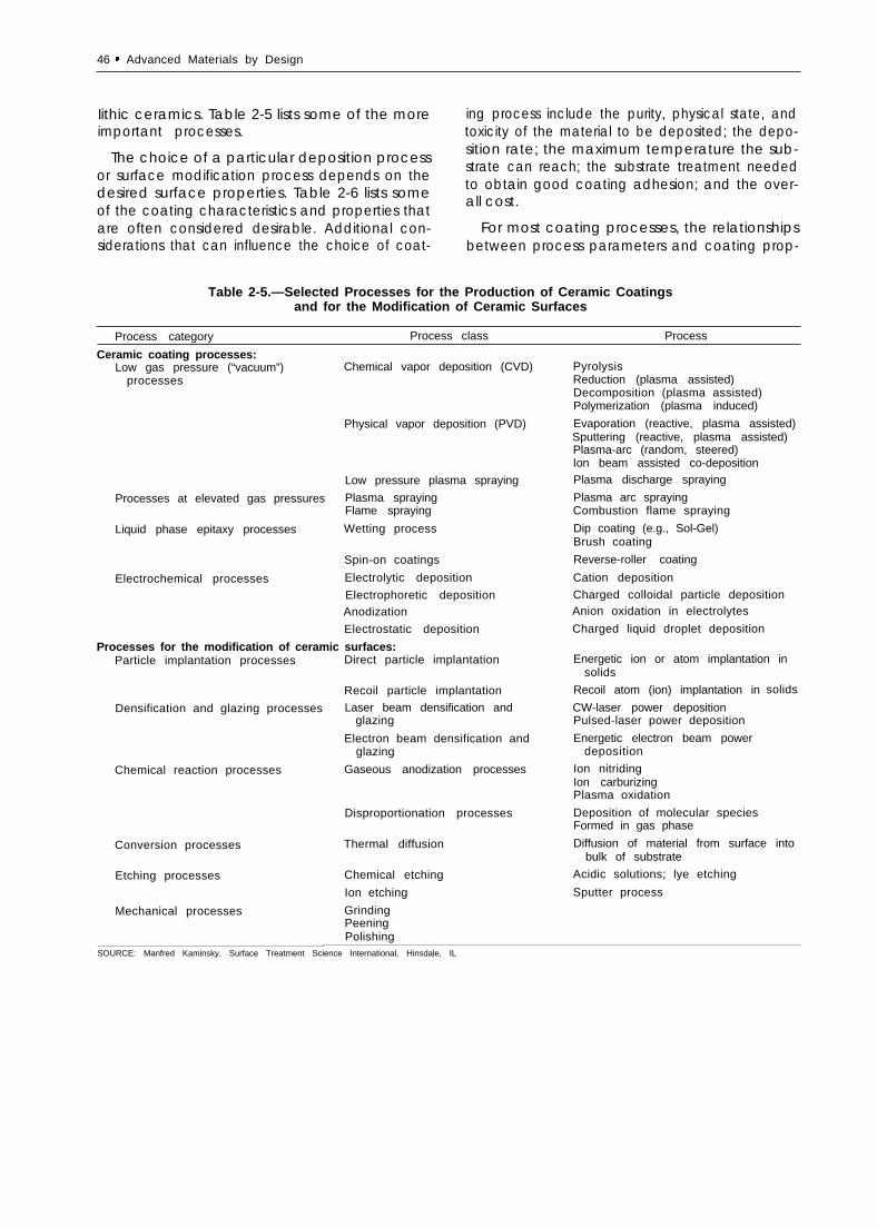
Iithic ceramics. Table 2-5 lists some of the moreimportant processes.
The choice of a particular deposition processor surface modification process depends on thedesired surface properties. Table 2-6 lists someof the coating characteristics and properties thatare often considered desirable. Additional con-siderations that can influence the choice of coat-
ing process include the purity, physical state, andtoxicity of the material to be deposited; the depo-sition rate; the maximum temperature the sub-strate can reach; the substrate treatment neededto obtain good coating adhesion; and the over-all cost.
For most coating processes, the relationshipsbetween process parameters and coating prop-
Table 2-5.—Selected Processes for the Production of Ceramic Coatingsand for the Modification of Ceramic Surfaces
Process category Process class Process
Ceramic coating processes:Low gas pressure (“vacuum”)
processes
Processes at elevated gas pressures
Liquid phase epitaxy processes
Electrochemical processes
Chemical vapor deposition (CVD)
Physical vapor deposition (PVD)
Low pressure plasma spraying
Plasma sprayingFlame spraying
Wetting process
Spin-on coatings
Electrolytic deposition
Electrophoretic depositionAnodization
Electrostatic deposition
Processes for the modification of ceramic surfaces:Particle implantation processes
Densification and glazing processes
Chemical reaction processes
Conversion processes
Etching processes
Mechanical processes
Direct particle implantation
Recoil particle implantation
Laser beam densification andglazing
Electron beam densification andglazing
Gaseous anodization processes
Disproportionation processes
Thermal diffusion
Chemical etching
Ion etching
GrindingPeeningPolishing
PyrolysisReduction (plasma assisted)Decomposition (plasma assisted)Polymerization (plasma induced)
Evaporation (reactive, plasma assisted)Sputtering (reactive, plasma assisted)Plasma-arc (random, steered)Ion beam assisted co-depositionPlasma discharge spraying
Plasma arc sprayingCombustion flame spraying
Dip coating (e.g., Sol-Gel)Brush coating
Reverse-roller coating
Cation deposition
Charged colloidal particle depositionAnion oxidation in electrolytes
Charged liquid droplet deposition
Energetic ion or atom implantation insolids
Recoil atom (ion) implantation in
CW-laser power depositionPulsed-laser power deposition
Energetic electron beam powerdeposition
Ion nitridingIon carburizingPlasma oxidation
Deposition of molecular speciesFormed in gas phase
solids
Diffusion of material from surface intobulk of substrate
Acidic solutions; lye etching
Sputter process
SOURCE: Manfred Kaminsky, Surface Treatment Science International, Hinsdale, IL

Ch. 2—Ceramics . 47
Table 2-6.—Characteristics and Properties ofCeramic Coatings Often Considered Desirable
Good adhesionPrecise stoichiometry (negligible contamination)Very dense (or very porous) structural morphologyThickness uniformityHigh dimensional stabilityHigh strengthHigh fracture toughnessInternal stresses at acceptable levelsControlled density of structural defectsLow specific densityHigh thermal shock resistanceHigh thermal insulating propertiesHigh thermal stabilityLow (or high) coefficient of frictionHigh resistance to wear and creepHigh resistance to oxidation and corrosionAdequate surface topography
SOURCE: Manfred Kaminsky, Surface Treatment Science International, Hinsdale,IL.
erties and performance in various environmentsare poorly understood. Coating providers tendto rely on experience gained empirically. Workis in progress to establish these relationships forcertain processes, e.g., ion beam- or plasma-assisted physical vapor deposition. In addition,improved deposition processes are required, par-ticularly for the coating of large components orthose having a complex shape. In view of the cur-rent widespread use of coated machinery com-ponents and projected future requirements forcomponents with advanced ceramic coatings, re-search in processing science for ceramic coatingsremains an important priority.
Chemically Bonded Ceramics
Hardened cement pastes and concretes fall inthe category of chemically bonded ceramics(CBCs) because they are consolidated throughchemical reactions at ambient temperaturesrather than through densification at high temper-ature. Owing to their low strength (comparedwith dense ceramics), concrete and other cemen-titious materials are not normally considered tobe advanced materials. However, in recent years,new processing methods have led to significantimprovements in the strength of chemicallybonded ceramics, and further development willprovide additional improvements.
Cements
Cements are chemically active binders that maybe mixed with inert fillers such as sand or gravelto form concrete. Cement pastes containing mi-nor additives such as organic polymers can alsobe used as structural materials. By far the mostcommon cement used in making CBCs is port-Iand cement. Portland and related cements arehydraulic; that is, they react with water to forma relatively insoluble aggregate. In hydraulic ce-ments, excess water is usually added to improvethe working characteristics, but this causes thehardened structures to be porous (the minimumporosity of fully-hydrated cements is about 28percent) and of low strength.10
Recently, workability of such cements has beenimproved by using a high-shear processing tech-nique together with pressing or rolling to removepores from a low-water calcium aluminate ce-ment paste containing 5 to 7 percent (by weight)organic polymers. The dense paste, which is
10Richard A. Helmuth, Portland Cement Association, Personalcommunication, August 1986.
[ ● ✎
*
Photo credits: lmperial Chemical Industries PLC
Top photo: Conventional Portland cement pastemicrostructure, showing large flaws (pores).
Bottom photo: Advanced cement paste microstructure,illustrating the absence of large pores
(magnification x 100).

48 ● Advanced Materials by Design
sometimes called macro-defect-free (MDF) ce-ment, has the consistency of cold modeling clay,and can be molded or extruded by techniquessimilar to those used for plastics.
The hardened cement paste has a compressivestrength approaching that of aluminum (table 2-7) and much lower permeability than ordinaryportland cement paste.11 Although MDF cementpastes cost 20 to 30 cents per pound (comparedwith 3 cents per pound for portland cementpaste), they are still significantly cheaper than me-tals and plastics.
The processing of hydraulic CBCs is very cheapbecause it involves only adding water, mixing,casting or molding, and permitting the materialto set at room temperature or slightly elevatedtemperature. Very little dimensional change oc-curs during the set and cure, so that parts can
be made to net shape. Due to the low process-ing temperature, it is possible to use any of a widevariety of reinforcing fibers, including metalfibers. However, the presence of organics makesthem unsuitable for use above 200° F (93° C).Further work is needed to improve the long-termstability of these materials.
Concrete
As chemical additives, such as organic poly-mers, have improved the properties of cementpastes, chemical and mineral additives have hada similar effect on concrete. Minerals such as flyash and microscopic silica particles help to fill inthe pores in the concrete and actually improvethe bonding in the cementitious portion. This re-sults in greater strength and reduced permeabil-ity.12 In a recently developed concrete, moltensulfur is used as a binder in place of cement. Sul-fur concrete has superior corrosion resistance inacidic environments and can be recycled byremelting and recasting without loss of the me-chanical properties.13
11 According to product Iiterature supplied by Imperial ChemicalIndustries, “New Inorganic Materials. ”
The compressive strength of typical concretestoday is around 5,000 psi (34 MPa), although con-cretes with strengths of 10,000 to 15,000 psi (69to 103 MPa) are becoming common. Under lab-oratory conditions, compressive strengths of atleast 45,000 psi (310 MPa) have been achieved,and there is no indication that the ultimatestrength is being approached .14 In concrete high-
Photo credit: CEMCOM Research Associates, Inc.
This tool, made from a cement-based composite,is used for autoclave forming of a fiber-epoxy
jet engine component.
12For a recent review, see Jan Skalny and Lawrence R. Roberts,“High Strength Concrete, ” Annual Review of Materials Science17:35, 1987.
13 U.S. Department of Interior, Bureau of Mines, Bulletin 678, "Sul -
fur Construction Materials,” by W.C. McBee, T.A. Sullivan, andH.L. Fike, 1985.
14 Sidney Mindess, “Relationships Between Strength and Micro-structure for Cement-Based Materials: An Overview, ” Materials Re-search Society Symposium Proceedings 42:53, 1985.
Table 2-7.—Comparison of the Mechanical Properties of Various Cements and Aluminum
Material Density (g/cm3) Flexural strength (psi)a Compressive strength (psi) Fracture energy (J/m2)
Portland cement paste . . . . . 1.6-2.0b 725-1,450 4,000-5,000 b 20Cement/asbestos . . . . . . . . . . 2.3 5,075 — 300Advanced cementsc. . . . . . . . 2.3-2.5 14,500-21,750 22,000-36,000 300-1,000Aluminum . . . . . . . . . . . . . . . . 2.7 21,750-58,000 42,000 10,000a1 MPa = 145 psi.bAccording to information supplied by the Portland Cement Association.cThe advanced cement has the following composition: 100 parts high alumina Cement; 7 parts hydrolyzed potyvinylacetate; 10-12 parts water.
SOURCE: Imperial Chemical Industries.

Ch. 2—Ceramics . 49
r ise bu i ld ings, the h igher compress ive s t rengths
permi t use of smal ler co lumns, wi th consequent
savings in space and materials.
Two deficiencies in concrete as a structural ma-terial are its low tensile strength and low tough-ness. A typical concrete has a tensile strength be-low 1,000 psi (7 MPa). Steel reinforcement barsare added to the concrete to provide tensilestrength. In prestressed concrete, high-strengthsteel wires under tension are used to keep theconcrete in a state of compression. To improvestrength and toughness, a variety of reinforcingfibers, including steel, glass, and polymers, havebeen tried, with varying degrees of success. 15
Compared with unreinforced materials, fiber rein-forcement can increase the flexural strength bya factor of 2.5 and the toughness by a factor of5 to 10.16 This reinforcement technology, whichdates back to the straw-reinforced brick of theancient Egyptians, requires fiber concentrationsthat are sufficiently low (usually 2 to 5 percentby volume) to preserve the flow characteristicsof the concrete, plus a chemically stable inter-face between the fiber and the concrete overtime. Asbestos fibers served this function for manyyears; however, because of the health hazards,new fibers are now being sought.
In recent years, several Japanese firms have de-veloped concretes reinforced with carbon andaramid fibers, and pitch-based carbon fiber-reinforced concrete curtain walls have been usedin Tokyo office buildings. Although the carbonfiber concrete panels cost 40 percent more thanprecast concrete, their light weight permits theuse of a lighter weight structural steel frame, re-sulting in overall construction cost savings. ’ 7
Nondestructive Evaluation
Nondestructive evaluation (NDE), which is ameans of determining properties of a structurewithout altering it in any way, has long been usedfor flaw detection in ceramic materials to improvethe reliability of the final product. In the future,NDE will be used for defect screening, material
characterization, in-process control, and life-cyclemonitoring. It will be applied to the starting mate-rials, during the process, and to the final product.
A key goal will be the evolution of NDE tech-niques amenable to automation and computeri-zation for feedback control. Powder and greenbody characterization will be critical tor materi-als processed from powders. For in-processcharacterization, it will be essential to determinethe relation between measurable quantities, ob-tained through the use of contact or noncontactsensors, and the desired properties. This will re-quire developments in sensor technology as wellas theories that can quantitatively relate the meas-u red N DE signal to the specific properties of in-terest.
In the past, a great deal of emphasis has beenplaced on the sensitivity of an NDE technique,that is, the size of the smallest detectable flaw.However, experience has shown that most qual-ity problems result not from minute flaws butfrom relatively gross undetected flaws introducedduring the fabrication process.18 Therefore, amore relevant criterion for reliabiIity purposes isperhaps the size of the largest flaw that can goundetected. To date, though, there has been verylittle emphasis on the reliability of NDE tech-niques, that is, the probability of detecting flawsof various sizes.
Cost-of-production estimates for high-perform-ance ceramic components typicalIy cite inspec-tion costs as accounting for approximately 50 per-cent of the manufacturing cost.19 Successful NDEtechniques for ceramic components, therefore,should meet two major criteria. First, they shouldreliably detect gross fabrication flaws to ensurethat the material quality of the component isequal to that of test specimens. Second, theyshould be able to evaluate the quality of a com-plex-shaped component in a practical manner.No single NDE technique for ceramics completelysatisfies these criteria. However, those that couldbe cost-effective for production-level inspectionsare identified in table 2-8.
‘ 51bld16Am~rlCan Cc)ncrete I nStlt Ute, ‘ ‘State-of-the-Art Report on Fiber
Reinforced Concrete , ” Repor t No, ACI 544.1 R-82, 1982.17Englneerlng fQe\v5 R e c o r d , Au~. 1, 1985, P. 16
IBR, Nathan Katz and Altred L. Broz, ‘‘Nondestructive Evaluation
Conslderatlons for Ceramtcs and Ceramic Mat r ix Composi tes , ” a
contractor report prepared for the Off Ice of Technology Assessment,
N o v e m b e r 1 9 8 5 .1 9I b i d

50 ● Advanced Materials by Design
Table 2.8.—Comparison of Some Possible Production-Level NDE Techniques for Structural Ceramics
Adaptability to Extent of developmentNDE technique Detected flaw type Sensitivity complex shapes required for commercialization
Visual (remote) . . . . . . . . . . surface fair good noneDye penetrant . . . . . . . . . . . surface good good noneRadiographic . . . . . . . . . . . . bulk 1-20/0 of specimen excellent none
thicknessUltrasonic . . . . . . . . . . . . . . . bulk and surface good poor someHolographic . . . . . . . . . . . . . surface good fair largeThermographic. . . . . . . . . . . surface poor excellent someProof test . . . . . . . . . . . . . . . any good, but may excellent none
introduce flawsSOURCE: Office of Technology Assessment, 1988.
HEALTH AND SAFETY
The most serious health hazard involved withceramics appears to stem from use of ceramicfibers and whiskers. Studies carried out at the Na-tional Cancer Institute have indicated that virtu-ally all durable mineral fibers having a diameterof less than 1 micrometer are carcinogenic whenintroduced into the lining of the lungs of labora-tory rats.20 The carcinogenicity drops with in-creasing diameter, such that fibers having di-ameters greater than 3 micrometers do not producetumors. Recent studies on commercially availablealuminosilicate fibers suggest that animals ex-
posed to the fibers develop an increased num-ber of lung cancers over time compared with acontrol group.21
No data on the effects of ceramic fibers orwhiskers on humans are available, and no indus-try standards for allowable fiber and whisker con-centrations in the workplace have been estab-lished. Until such data become available, theanimal studies suggest that these fibers should beconsidered carcinogenic, and they should betreated in a manner similar to asbestos fibers.
20 Mear] F. Stanton, et al., journal of the National cancer /f?Sti- ZI Phillp j. Landrigan, M. D., The Mount Sinai Medical Center, per-ture 67:965-75, 1981. sonal communication, August 1986.
APPLICATIONS OF STRUCTURAL CERAMICS
Figure 2-2 shows an estimated timetable for theintroduction of ceramic products in various cat-egories. It shows that some advanced structuralceramics are in production, some have near-termpotential for production, and some are far fromproduction.
Current Applications
in the United States, ceramics such as aluminaand silicon carbide are already well establishedin commercial production for many structural ap-plications in the categories of wear parts, cuttingtools, bearings, membranes, filters, and coatings.The ceramics portion of these markets is currently
small (generally less than 5 percent).22 However,substantial growth in ceramics production is ex-pected to occur over the next 25 years in re-sponse to increasing overall market demand, in-crease in the ceramics market share, and spin-offapplications.
Current U.S. military applications for ceramicsinclude radomes, armor, and infrared windows(see section entitled, Military Applications andProduction). In Japan, ceramics are in limited pro-duction in discrete automotive engine compo-
22 U.S. Department of Commerce, A Competitive Assessment of
the U.S. Advanced Ceramics Industry (Washington, DC: U.S. Gov-ernment Printing Office, March 1984), pp. 38-39.

Figure 2.2.—Estimated Scenario for Implementation of Ceramic Components in Structural Application Categories
Wear parts
Cutting tools
Advanced construction
Military applications
Bearings
Bioceramics
Heat exchangers
Electrochemical devices
Heat engines:
Gasoline automotive
Diesel automotive
Automotive turbine
Other turbines
Coatings
products
1960 1965 1970 1975 1980 1985 1990 1995 2000 2005 20101 I I I I I
Al2O 3 sic PSZ Si3N4 CompositesTTA TZP Si3N4-BN
Al2O 3 Al2O3-TiC Si3N4 Al2O3-SiCI coating TTA Advanced materials
chemically Compositesbonded ceramics
B4C Armor Coatings Bearings Diesels TurbinesRadomes Isolated components
I AI2O3 Si3N4 Military
Al2O3 FDA hip Orthopedic Advancedclinical approval and dental materials
Recuperated Rotary Tubular Cogeneration Fhwdfurnaces Military Industrial boundary
02 sensors Electrochlorination Na-S battery Fuelrod02 pump
F
Exhaust port liner Piston pinTurbochargerCam follower
Pre-chamber, coatings Isolated partsGlow plug Uncooled engine
Isolatedcomponents
Wear and Cutting Turbine Minimum—cookdcorrosion toots components diesel
I resistance
SOURCE: David W. Richerson, “Design, Processing Development, and Manufacturing Requirements of Ceramics and Ceramic Matrix Composites, ” contractor report prepared for the Office
of Technology Assessment, December 1985.

52 . Advanced Materials by Design
nents such as turbocharger rotors, glow plugs,and precombustion chambers for diesel engines.In West Germany, the automobile manufacturerPorsche uses ceramic exhaust port liners on onemodel. To gain experience in fabricating advancedceramics, Japanese firms use advanced manufac-turing techniques to produce such consumerproducts as ceramic ballpoint pen tips, tools, andscissors. These products also help to promotefamiliarity with the new materials among the Jap-anese public.
In the United States, research funding forknown near-term markets is currently being pro-vided by industry. Much of the funding is directedtoward development of new or improved ceramicor CMC materials. Key objectives are to achieveimproved toughness, higher reliability, and lowercost. Development of silicon nitride, transforma-tion-toughened ceramics, and composites hasyielded materials with enhanced toughness andreliability, but costs are still high and reliabilityremains a problem. Currently, progress is beingmade in resolving these limitations, and forecastsindicate there will be large increases in the mar-ket share for ceramics.
Near-Term Applications
U.S. production in the near term (the next 10to 15 years) is projected in advanced construc-tion products, bearings, membranes for foodprocessing applications, bioceramics, heat ex-changers, electrochemical devices, isolated com-ponents for internal combustion engines, and mil-itary applications. The technology feasibility forthese applications has generally been demon-strated, but scale-up, cost reduction, or designoptimization are required.
Although much of the feasibility demonstrationhas occurred in the United States, foreign industryand government/industry teams, particularly inJapan, have more aggressive programs to com-mercialize the near-term applications. Large mar-kets are at stake; foreign dominance of these mar-kets would adversely affect the U.S. balance oftrade.
Far-Term Applications
Some potential applications of ceramics requiresolution of major technical and economic prob-lems. These high-risk categories are categorizedas far-term (greater than 15 years away). The ulti-mate payoff may be large, but it is not possibleto predict confidently that the problems will beovercome to achieve the benefits.
Far-term applications include the automotivegas turbine engine, the advanced diesel, someelectrochemical devices such as fuel cells, someheat exchangers, and some bearings. A varietyof other turbines, especially those for aircraftpropulsion and utility-scale power generation,should also be categorized as far-term.
Substantial design, material property, and man-ufacturing advances are necessary to achieve pro-duction of applications in the far-term category.In general, risk is perceived by industry to be toohigh and too long-range to justify funding theneeded developments. Advancement will likelybe driven by government funding. In many ofthese categories, military use will predate com-mercial use.
Markets for Advanced StructuralCeramics
Estimated structural ceramics markets in theyear 2000 for several of the categories listedabove are shown in figure 2-3.
Wear Parts
Wear parts include such applications as seals,valves, nozzles, wear pads, grinding wheels, andliners. The Department of Commerce has esti-mated that by the year 2000 ceramics could cap-ture roughly 6 percent of the wear-parts market,which is currently dominated by tungsten car-bide, cermets, and specialty steels. With the to-tal market estimated at $9 billion, the ceramicportion would be $540 million.23
‘] Ibid., p. 35,

Ch. 2—Ceramics ● 5 3
Figure 2-3.—Projected U.S. Markets for Structural‘Ceramics in the Year 2000 (billions of dollars)
1 . 0
0.5
SOURCES: aU.S. Department of Commerce, “A Competitive Assessment of theU.S. Advanced Ceramics Industry" (Washington, DC, U.S. Govern-ment Printing Office, March 1984)
bE.P. Rothman, J. Clark, and H.K. Bowen, "Ceramic Cutting Tools: AProduction Cost Model and an Analysis of Potential Demand," Ad-vanced Ceramic Materials, American Ceramics Society, Vol 1, No.4, October, 1986, pp 325-331.
C High Technology, March, 1988, p. 14.d Business Communications Co., Inc., as reported in Ceramic Indus-
try, Jan 1988, p. 10.eDavid W. Richerson, "Design, Processing Development, and Manu-
facturing Requirements of Ceramics and Ceramic Matrix Compos-ites," contractor report prepared for the Office of TechnologyAssessment, December 1985
f Assumes a doubling from 1986. Paul Hurley, "New Filters Can CleanUp in New Markets," High Technology, August 1987
Cutting Tools
Ceramics have demonstrated capability as cut-ting tools, especially in competition with tung-sten carbide-cobalt cermets as inserts for metalturning and milling operations. The advantage ofceramics compared with carbides is retention ofhigh hardness, strength, and chemical inertnessto temperatures in excess of 1000° C (18320 F).This permits use of the ceramics at much highermachining speeds than can be tolerated bycarbides,
However, the ceramics have lower toughnessthan the carbide materials, and have only been
used successfully in the limited operations of turn-ing and milling. A further impediment to the useof ceramics, especially in the United States, hasbeen equipment limitations; much of the produc-tion metal machining equipment does not havethe rigidity or speed capability to use ceramics.
A 1986 projection for ceramic and ceramic-coated cutting tools (the largest portion of whichare inserts) places the growth rate at about 6 per-cent per year from a present market of $600 mil-lion to a market of over $1 billion by 1995. 24 Thevast majority of this market is coated carbide tool-ing. A second projection, for only the solid ce-ramic insert cutting tool market, is $128 millionoverall market by the year 2000. 25
Bearings
High-performance ceramic bearings have beendeveloped for military applications such as mis-siles. The primary candidate material is hotpressed silicon nitride. Ceramics offer resistanceto low-temperature corrosion, high-temperaturestability, low density, and the ability to operatefor a moderate length of time with little or no lu-brication. Hot isostatic pressing is being devel-oped to improve properties and to decrease costby permitting near-net-shape fabrication.
The military developments will yield a technol-ogy base that can be applied to commercial prod-ucts such as instrumentation bearings, hydrau-lic and pneumatic activator systems, and ceramiccoatings on the foils in gas bearings. Potential ce-ramic bearing markets have been estimated tobe $300 million per year.26
Membranes
Membrane filters are used in a wide variety ofseparation and purification processes, and mar-kets are projected to increase from $500 millionin 1986 to $2 billion by 1995. Some of the fastestgrowing segments are expected to be food and
24 G. Shroff, SRI International, “Business Opportunities in Ad-vanced Structural Ceramics and Ceramic Coatings, excerpted InAdvanced Ceramic Mater;a/s 1(4):294, October 1986.
25 Elaine P. Roth ma n, Joel Clark, and H. Kent Bowen, ‘‘Ceram IC
Cutting Tools: A Production Cost Model and an Analysis of Poten-tial Demand, ” Advanced Ceramic Materials, American Ceramic So-ciety 1(4):325-331, October 1986.
26 High Technology/, March 1986 p. 14.

54 “ Advanced Materials by Design
beverage processing, aqueous waste processing,diesel engine exhaust filters, and gas separation.Although ceramic membranes cost more than themore well-established polymer membranes, ce-ramics offer a number of performance advan-tages, including resistance to high temperatures,chemical and mechanical stability, and ease ofcleaning. In 1986, markets for ceramic membraneswere estimated at $200 million, and growth ratesof up to 30 percent are projected into the 1990s.27
Coatings
Ceramic coatings should be considered an ex-tremely important technology for extending theperformance of metal components, and, in somecases, they may be an excellent alternative tomonolithic ceramics. They provide a variety ofbenefits, including abrasion resistance, thermalprotection, corrosion resistance, and high-tem-perature lubrication. Applications include ultra-hard coatings for cutting tools, thermal insulationand lubricating coatings for adiabatic diesel en-gines and cooled gas turbines, and bioactive glasscoatings for metal orthopedic implants. The listcould be expanded to include other sectors suchas mining (e.g., drills); utilities (e.g., turbine-
27Paul Hudey, “New Filters Clean Up in New Markets,” HighTechnology, August 1987.
generator sets, heat exchangers); agriculture (e.g.,plows and tillers); and aerospace (e.g., bearings,power transfer assemblies, and actuator drivesystems).
The availability of advanced ceramic coatingsis expected to be a significant benefit to the U.S.economy. The value of the market for ceramiccoatings is not easily assessed because the rangeof applications is so wide. In 1985, markets forceramic coating materials were estimated at $1billion worldwide, of which about 60 to 70 per-cent was domestic.28 This estimated market in-cludes jet engine, printing, chemical, textile, andtool and die applications. This list could be greatlyexpanded in the future to include wear parts,bearings, biomaterials, heat exchangers, and au-tomotive components.
Advanced Construction Products
Potential applications of advanced cement-based materials include floors, wall panels, androof tiles, in addition to pipes, electrical fittings,and cabinets. The cements can be laminated withwood or foam to form hard, decorative, and pro-tective surfaces.29 Advanced cement pastes cost$0.20 to $0.30 per pound (compared with $0.75to $2 per pound for metals and plastics), and theycould displace these materials in the future inmany common uses.
The development of a cost-effective, durable,high-tensile, and high-compressive strength con-crete would have dramatic implications for theinfrastructure of the United States. It has beenestimated that between 1981 and the end of thecentury, the Nation will spend about $400 bil-lion on replacement and repair of pavements andabout $103 billion to correct bridge deficien-cies. 30 Cost savings of about $600 million per yearcould result from implementing new technol-ogies.31
Zsjulie M. schoerrung, Elaine P. Rothman, and Joel P. Clark, “prop-erties, Costs, and Applications of Ceramics and Ceramic MatrixComposites,” a contractor report prepared for the Office of Tech-nology Assessment, December 1985.
Zglmperial Chemical Industries, “New Inorganic Materials” (prod-uct literature).
JoNational Research Council, Transportation Research Board,America’s Highways: Accelerating the Search for Innovation, spe-cial report No. 202, 1984.
31 Ibid.

Ch. 2–Ceramics “ 55
A spring made from a high-strength cement, formed by eThe spring is not Intended for any practical use, but
Photo credits: CEMCOM Research Assiciates, Inc.
xtrusion processing. Left: natural length. Right: compressed.demonstrates the versatility and resilience of the material.

56 . Advanced Materials by Design
In addition to reducing repair and maintenancecosts, new materials would provide other bene-fits. For instance, high compressive strength con-crete can be used to reduce the number andthickness of concrete bridge girders, significantlyreducing the structural weight.32 In concrete high-rise buildings, the use of such materials permitsa reduction in the diameter of the columns, thusfreeing up additional floor space.
There are major barriers to the developmentand implementation of new technologies in theconstruction industry. Some of those most oftencited are industry fragmentation (e.g., some23,000 Federal, State, and local agencies oper-ate the Nation’s highway system); an arrangementthat awards contracts to the lowest bidder; andlow industry investment in research as a percent-age of sales (the steel industry, by contrast, in-vests eight times more).33 The low investment isdue in part to the fact that the principal benefitsof the use of better materials accrue to the ownerof the highway or bridge (the taxpayer) ratherthan to the cement producer. 34
The Surface Transportation Assistance Act of1986 (Public Law 100-1 7) sets aside 0.25 percentof Federal aid highway funds for the 5-year, $150million Strategic Highway Research Program. Theprogram, which is administered by the NationalResearch Council, has targeted six priority re-search areas for support: asphalt characteristics,$50 million; long-term pavement performance,$50 miIlion; maintenance cost-effectiveness, $20million; concrete bridge components, $10 mil-lion; cement and concrete, $12 million; and snowand ice control, $8 million. 35
Bioceramics
Bioceramics, or ceramics for medical applica-tions such as dental or orthopedic implants, rep-resent a major market opportunity for ceramicsin the future. The overall worldwide market forbiocompatible materials is currently about $3 bil-lion, and this is expected to double or triple in
32J. E. Carpenter, “Applications of High Strength Concrete for High-way Bridges, ” Pub/ic Roads 44(76), 1980.
IJNational Research Council, op. cit., 1984.34Ibid.35"Construction and Materials Research and Development for the
Nation’s Public Works,” OTA staff paper, June 1987.
the next decade.36 Ceramics could account for25 to 30 percent of this market.37 However, notall estimates are so optimistic. One projectionplaces the U.S. bioceramics market at $8 millionin 1987, increasing to $60 million by 2000.38
Bioceramics may be grouped into three cate-gories: nearly inert, surface-active, and resorba-ble.39 Nearly inert ceramics can be implanted inthe body without toxic reactions. These materi-als include silicon nitride-based ceramics, trans-formation-toughened zirconia, and transforma-tion-toughened alumina.
Surface-active ceramics form a chemical bondwith surrounding tissue and encourage ingrowth.They permit the implant to be held firmly in placeand help prevent rejection due to dislocation orto influx of bacteria. Surface-active ceramics thatwill bond to bone include dense hydroxyapatite,surface-active glass, glass-ceramic, and surface-active composites. The function of resorbablebioceramics is to provide a temporary space filleror scaffold that will serve until the body can grad-ually replace it.
Resorbable ceramics are used to treat maxil-Iofacial defects, for filling periodontal pockets, asartificial tendons, as composite bone plates, andfor filling spaces between vertebrae, in bone,above alveolar ridges, or between missing teeth.An early resorbable ceramic was plaster of paris(calcium sulfate), but it has been replaced bytrisodium phosphate, calcium phosphate salts,and polylactic acid/carbon composites.40
Any new material intended for use in the hu-man body must undergo extensive testing beforeit is approved. Preclinical testing, clinical studies,and followup generally take a minimum of 5 yearsto complete.41 However, ceramics have been in
36 Larry L. Hench and June Wilson Hench, “Biocompatibility ofSilicates for Medical Use, ” Silicon Biochemistry, CIBA FoundationSymposium, No. 121 (Chichester, England: John Wiley & Sons,1986), pp. 231-246.
37 Larry L. Hench, University of Florida, personal communication,
August 1986.38 According to Business Communications Co., Inc., as reported
in Ceramic Industry, January 1988, p. 10.3 9 J . W . B o r e t o s , " C e r a m i c s i n C l i n i c a l C a r e , ” A m e r i c a n C e r a m i c s
Society Bulletin 64(8):630-636, 1985.40 Ibid.41 Edwardo March, Food and Drug Administration, personal com-
munication, August 1986.

Ch. 2—Ceramics . 57
42 Richerson, op. cit., footnote 4
Heat Exchangers
Ceramic heat exchangers are cost-effective be-cause they can use waste heat to reduce fuel con-sumption. Heat recovered from the exhaust ofa furnace is used to preheat the inlet combus-tion air so that additional fuel is not required forthis purpose. The higher the operating tempera-ture, the greater the benefit. Ceramic systemshave the potential to reduce fuel consumptionby more than 60 percent.43
Ceramic heat exchangers may be used in a va-riety of settings, including industrial furnaces, in-dustrial cogeneration, gas turbine engines, andfluidized bed combustion, The size of the unit,manufacturing technique, and material all varydepending on the specific application. Sinteredsilicon carbide and various aluminosilicates havebeen used in low-pressure heat exchangers be-cause of their thermal shock resistance; however,the service temperature of these materials is cur-rently limited to under 2200° F (1204° C). Siliconcarbide is being evaluated for higher tempera-tures, but considerable design modifications willbe necessary .44
Federal Government support has been neces-sary to accelerate development of the ceramicmaterials and system technology for heat ex-changers, in spite of the design projections of sig-nificant fuel savings and short payback time. Thematerial manufacturers, system designers, andend users have all considered the risks too highto invest their own funds in the development andimplementation of a system.
Three of their specific concerns are: 1) the highinstalled cost (up to $500,000 for a unit that de-livers 20 million British thermal units per hour),which represents a significant financial risk to theuser for a technology that is not well proven; 2)many potential end users are in segments of in-dustry that presently are depressed; and 3) de-signs vary according to each installation, leadingthe user to want a demonstration relevant to hisparticular situation.
43s. M. Johnson ancj D.J. Rowcliffe, SRI International Report to
EPRI, “Ceramics for Electric Power-Generating Systems, ” January1986.
44 Richerson, op. cit., footnote 4.

58 ● Advanced Materials by Design
Many of the ceramic heat exchanger programswere initiated in the 1970s when there was a na-tional sense of urgency concerning the energycrisis. In recent years, declining fuel prices havegenerally reduced this sense of urgency. As longas low fuel prices persist, this could delay thewidespread implementation of ceramic heat ex-changers for waste heat recovery.
Electrochemical Devices
Although not strictly structural applications ofceramics, devices in this category use ceramicsfor both their electrical and structural properties.Typically, the ceramic, such as zirconia or betaalumina, serves as a solid phase conductor forions such as oxygen or sodium. Examples includeoxygen sensors, oxygen concentration cells, solidoxide fuel cells, the sodium-sulfur battery, sodiumheat engine, and electrodes for metal winningand electrochlorination cells. As a group, theseapplications could comprise a market of over$250 million for ceramics by the year 2000.45
Heat Engines
The advantages of using ceramics in advancedheat engines have been widely publicized. Theseinclude increased fuel efficiency due to higherengine operating temperatures, more compactdesigns, and reduction or elimination of the cool-ing system.46 Ceramics are being considered inthree general categories: 1 ) discrete componentssuch as turbocharger rotors in metal reciprocat-ing engines; 2) coatings and monolithic hot-section components in advanced diesel designs;and 3) all-ceramic gas turbine engines.
Some analysts have predicted that componentsfor heat engines will be the largest area of growthfor structural ceramics over the next 25 years.projected market estimates vary widely. Earlierestimates tended to be more optimistic, with sev-eral analysts projecting U.S. ceramic heat enginemarkets around $5 billion by the year 2000. TheDepartment of Commerce has conservatively esti-mated a U.S. market of $56 million by 1990 and
45 Ibid.46R. Nathan Katz, “Applications of High Performance Ceramics
in Heat Engine Design, ” Materials Science and Engineering 71 ;227-249, 1985.
$840 million by 2000.47A study by Charles RiverAssociates estimates U.S. consumption of ceramicheat engine parts at $25 to $45 million in 1990and $920 million to $1.3 billion by 2000.48
Some structural ceramic components are al-ready in limited production in automobile en-gines. Ceramic precombustion chambers andglow plugs for diesels, as well as ceramic turbo-charger rotors, are now i n production i n currentmodel Japanese cars.
Ceramic engine components markets willgrow, but not to a level that will account for theprojected $1 billion sales for heat engine com-ponents in the year 2000. Growth to this levelwould require material and design technologybreakthroughs, as well as manufacturing scale-up and cost reduction. In view of these techni-cal and economic barriers, the more conserva-tive estimates are likely to be the more accurate.
Gasoline Engines
The automotive internal combustion gasolineengine offers a vast market for materials. Totalsales for 1985 of cars and trucks in the free worldhave been estimated at 38,7 million units.49 Anypart replacement or new part would representa volume market with substantial sales, even ifthe unit price were small. However, current en-gine designs are considered by automotive com-panies to be mature, reliable, and cost-effective.
Very few incentives for change exist. Cost re-duction does remain a significant incentive, butthis goal is extremely difficult to satisfy for a newmaterial, whose introduction may require re-design of adjacent parts, retooling, and modifi-cation of the production line.
Another incentive is to develop a new technol-ogy that may be applicable to advanced designs.This would involve both generic and directedR&D, with the primary objective of maintaininga competitive position. Ceramics within thiscategory that have potential for production in-
47 U.S. Department of Commerce, op. cit., footnote 22.
qBChar[es River Associates report prepared for the National Bu-reau o f S tandards , “Techno log ica l and Economic Assessment ot
Advanced Ceramic Materials, Vol. 2: A Case Study of Ceramics in
Heat Engine Appl icat ions, ” NBS-GCR 84-4760-2, August 1984.qgRICherSon, op. c i t . , foo tnote 4 .

Ch. 2—Ceramics . 59
(w 1 2 3 4 5 6 7 8 9 110 11 12 1,3 14 15 , I* 1 1 9 21(1 1,
I ,1 \ ~ , I I I ! ,! t j I ; I , ; ! [I ~ I 1 ‘1 ill:ll ’161 l:” 1 ’11 I I Ii
Photo credit: The Garrett Corp
Ceramic turbocharger turbine rotors
elude exhaust port liners, cam followers, andturbocharger components. To date, U.S. firmshave not introduced these products, althoughR&D programs continue.
The United States remains behind Japan inprocuring the advanced production equipmentneeded to produce ceramic turbocharger rotors.U.S. automotive companies do not appear tohave the same level of confidence as the Japanesethat a ceramic turbocharger rotor market will de-velop. In spite of this, U.S. industry is still fund-ing considerable R&D on ceramic turbochargerrotors. One study has estimated that if a ceramicrotor price of$15 can be reached and if perform-ance and reliability are acceptable, a worldwide
market of $60 million could be generated for ce-ramic turbocharger rotors by the year 2000.50
The ceramic turbocharger rotor has a signifi-cance far beyond its contribution to the perform-ance of the engine. it is regarded as a forerun-ner technology to far more ambitious ceramicengines, such as the advanced gas turbine. De-sign, fabrication, and testing methods developedfor the turbocharger rotor are expected to serveas a pattern for subsequent ceramic engine tech-nology efforts.
5’JElaine P. Roth man, “Advanced St ruc tura l Ceramics : Techni-
cal/Economic Process Modeling of Production and a Demand Anal-ysis for Cutting Tools and Turbochargers, ” Materials Systems Lab-oratory, Massachusetts Institute of Technology, August 1985.
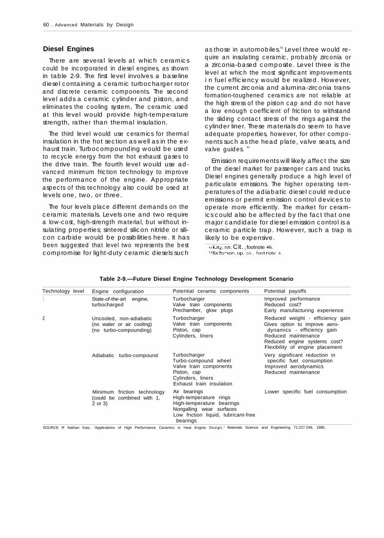
60 . Advanced Materials by Design
Diesel Engines
There are several levels at which ceramicscould be incorporated in diesel engines, as shownin table 2-9. The first level involves a baselinediesel containing a ceramic turbocharger rotorand discrete ceramic components. The secondlevel adds a ceramic cylinder and piston, andeliminates the cooling system, The ceramic usedat this level would provide high-temperaturestrength, rather than thermal insulation.
The third level would use ceramics for thermalinsulation in the hot section as well as in the ex-haust train. Turbocompounding would be usedto recycle energy from the hot exhaust gases tothe drive train. The fourth level would use ad-vanced minimum friction technology to improvethe performance of the engine. Appropriateaspects of this technology also could be used atlevels one, two, or three.
The four levels place different demands on theceramic materials. Levels one and two requirea low-cost, high-strength material, but without in-suIating properties; sintered silicon nitride or sili-con carbide would be possibilities here. It hasbeen suggested that level two represents the bestcompromise for light-duty ceramic diesels such
as those in automobiles.51 Level three would re-quire an insulating ceramic, probably zirconia ora zirconia-based composite. Level three is thelevel at which the most significant improvementsi n fuel efficiency wouId be realized. However,the current zirconia and alumina-zirconia trans-formation-toughened ceramics are not reliable atthe high stress of the piston cap and do not havea low enough coefficient of friction to withstandthe sliding contact stress of the rings against thecylinder liner. These materials do seem to haveadequate properties, however, for other compo-nents such as the head plate, valve seats, andvalve guides. 52
Emission requirements will likely affect the sizeof the diesel market for passenger cars and trucks.Diesel engines generally produce a high level ofparticulate emissions. The higher operating tem-peratures of the adiabatic diesel could reduceemissions or permit emission control devices tooperate more efficiently. The market for ceram-ics could also be affected by the fact that onemajor candidate for diesel emission control is aceramic particle trap. However, such a trap islikely to be expensive.
JI Katz, op. Cit. r footnote 46.J~Richer50n, op. cit . , fOOt nOte 4.
Table 2-9.—Future Diesel Engine Technology Development Scenario
Technology level Engine configuration Potential ceramic components Potential payoffs
1 State-of-the-art engine,turbocharged
2 Uncooled, non-adiabatic(no water or air cooling)(no turbo-compounding)
Adiabatic turbo-compound
Minimum friction technology(could be combined with 1,2 or 3)
TurbochargerValve train componentsPrechamber, glow plugs
TurbochargerValve train componentsPiston, capCylinders, liners
TurbochargerTurbo-compound wheelValve train componentsPiston, capCylinders, linersExhaust train insulation
Air bearingsHigh-temperature ringsHigh-temperature bearingsNongalling wear surfacesLow friction liquid, lubricant-free
bearings
Improved performanceReduced cost?Early manufacturing experience
Reduced weight - efficiency gainGives option to improve aero-
dynamics - efficiency gainReduced maintenanceReduced engine systems cost?Flexibility of engine placement
Very significant reduction inspecific fuel consumption
Improved aerodynamicsReduced maintenance
Lower specific fuel consumption
SOURCE R Nathan Katz, “Applications of High Performance Ceramics in Heat Engine Design,” Materials Science and Engineering 71:227-249, 1985,

Ch. 2—Ceramics ● 6 7— .
Ceramic coatings may be an alternative tomonolithic ceramics in diesel applications. Zir-conia coatings can be plasma-sprayed onto metalcylinders to provide thermal insulation. In a jointprogram between the U.S. Army Tank Automo-tive Command and Cummins Engine Co., thecombustion zone of a commercial Cummins NHdiesel engine was coated with a zirconia-basedceramic and installed in a 5-ton Army truck,minus the cooling system. The engine accumu-lated over 9,375 miles (1 5,000 kilometers) of suc-cessful road testing. 53 The current state-of-the-a t-tthickness of zirconia coatings is 0.03 to 0.05 inch(0.762 to 1.27 millimeter). It is estimated thatthicknesses of 0.125 inch (3. 175 millimeter) willbe required to provide thermal insulation com-parable to monolithic zirconia.54 The coating isnot as impermeable or as resistant to thermalshock as the monolithic zirconia. However, thecoated metal part has greater strength and tough-ness than the all-ceramic part.
In the past, confusion has arisen because iden-tical configurations of ceramic and metal engineshave not been compared. It is important to sep-arate out the configuration options, such asturbocharging, turbocompounding, heat recov-ery, cooling, etc., from the material options toisolate the benefits of the use of ceramics. Fail-ure to do this has led to overestimation of thebenefits of ceramics. For instance, a recent studyof a ceramic diesel design funded by the Depart-ment of Energy indicates that:
. . . a practical zirconia-coated configuration witha cooled metal liner, intercooled, with combinedturbocompounding and Rankine cycle exhaustheat recovery{ provides a 26 percent increase inthermal efficiency over a metallic, cooled, tur-bocharged, intercooled, baseline engine. 55
However, the bulk of the performance im-provement was attributed to the turbocom-pounding and the Rankine cycle exhaust heat re-covery. Only 5.1 percent was attributed to theimproved thermal insulation. Recent work at Ford
‘] Katz, op. ctt,, Iootnote 46.“)’BJ)] Marrcl)er. Cummin\ En~lne Co,, personal c CJmmunic at Ion,
Augu\t 1986.“T. ,Morel, et ~1., ‘ ‘lMet hods tor Heat Tra n ster and T herma I Anal-
Y ~r~ ~1 [jtomo[ii tJ T<>< /l-ysis ot lnsulateci Dwwl\, ” Pro( eedlng.$ of the -nolog~, Dc’y c’lopment ~-(~ntr,]ctor$ Coord/nat/on ,~leeting ~ IXarhorn,JM I Soc Iety of ,Automotive Engineers, March 1986).
Motor Co. also showed a 5- to 9-percent increasein fuel efficiency in an uncooled test engine fittedwith ceramic inserts, compared to the baselinewater-cooled design. 56
Charles River Associates predicts that the un-cooled ceramic diesel engine system will be thefirst to be commercialized. 57 It projects that theinitial introduction will be in the late 1980s toearly 1990s, and could account for 5 percent ofnew engines manufactured in 1995.
This projection is more optimistic than theabove discussion would imply. Zirconia materi-als do not yet exist that can be used for level threetechnology, wherein the greatest fuel efficienciesare expected. It remains to be seen whether theelimination of the cooling system will providesufficient incentives to U.S. automakers to com-mercialize level two ceramic technology.
Japan in particular has very active researchprograms both in material and diesel enginedevelopment. IsUzU, the strongest ceramic engineadvocate of all of the Japanese auto companies,has reported more than 300 miles (480 kilome-ters) of road testing and is projecting 1990 pro-duction, 58 Toyota has plans to produce an all ce-ramic diesel, using injection molded and sinteredsilicon nitride by 1992. Every part will be prooftested. The largest Japanese automakers all maintain extensive research activities in the area oceramic engines.59
Automotive Gas Turbines
The major incentive for using ceramics in tur-bines is the possibility of operating the engine atturbine inlet temperatures up to about 2500° F(1371° C), compared with superalloy designs, thatare limited to about 1900° F (1038° C) withoutcooling. This temperature difference translatesinto an increased thermal efficiency from around

62 . Advanced Materials by Design
40 percent to nearly 50 percent.60 Power in-creases of 40 percent and fuel savings of around10 percent have been demonstrated in researchengines containing ceramic components.61 Otherpotential advantages include reduced engine sizeand weight, reduced exhaust emissions, and thecapability to burn alternative fuels, such aspowdered coal.
Structural ceramics represent an enabling tech-nology for the automotive gas turbine; i.e., ce-ramics are the key to designing and manufactur-ing an automotive turbine that can compete incost or performance with current gasoline anddiesel engines. Extensive design, materials, andengine efforts have been made over the past 15years in the United States, Europe, and Japan.These efforts have resulted in significant progressin design methods for brittle materials, the prop-erties of silicon nitride and silicon carbide, fabri-cation technology for larger and more complexceramic components, NDE and proof testing, andengine assembly and testing.
Ceramic components have been operated inprototype turbine engines in West Germany,Sweden, Japan, and the United States. The testsin the United States have involved highly in-strumented development engines in test cells. 62
Current programs have achieved over 100 hoursof operation at temperatures above 2000° F(1093° C).63 These achievements, although im-pressive, are still far from the performance re-quired of a practical gas turbine engine, whichwill involve continuous operation above 2500°F (1 3710 C). The limiting component in these en-gines appears to be the rotor, which must spinat about 100,000 rpm at these temperatures. Themost reliable rotors available have generally beenmanufactured in Japan.64 The target automotive
60John Mason, Garrett Corp., presentation at the Society of Au-
tomotive Engineers International Congress and Exposition, Detroit,Ml, February 1986.
61 David W, Richerson and K.M. johansen, ‘‘Ceramic Gas Tur-bine Engine Demonstration Program, ” final report, DARPA/Navycontract NOO024-76-C-5352, May 1982,
b’David W, Richerson, “Evolution in the U.S. of Ceramic Tech-nology for Turbine Engines, American Ceramics Society Bulletin64(2):282-286, 1985.
b~Mason, op. cit.bJRic hard Helms, General Motors Corp., presentation at the
Society of Automotive Engineers International Congress and Expo-sltlon, Detroit, Ml, February 1986.
gas turbine engine is designed to provide about100 horsepower with fuel efficiencies of about43 miles per gallon for a 3,000-pound automo-bile.65
The automotive gas turbine would be a morerevolutionary application of ceramics than thediesel. The diesel engine is a familiar technologyand incorporation of ceramics can occur instages, consistent with an evolutionary design.The gas turbine, on the other hand, representsa completely new design requiring completelynew tooling and equipment for manufacture, Be-cause of the remaining technical barriers to ce-ramic gas turbines and the fact that they repre-sent a complete departure from current designs,it is unlikely that a ceramic gas turbine passen-ger car could be produced commercially before2010. 66 In view of this long development time,it appears possible that this propulsion systemcould be overtaken by other technologies, includ-ing the ceramic diesel. One factor that wouldfavor the turbine engine would be dramaticallyincreased fuel costs. In the case that traditionalfuels became scarce or expensive, the turbine’scapability to burn alternative fuels could makeit the powerplant of choice in the future.
In summary, the outlook for ceramic heat en-gines for automobiles appears to be highly un-certain. The performance advantages of ceramicengines are more apparent in the larger, moreheavily loaded engines in trucks or tanks thanthey are in automobiles. Ceramic gas turbines andadiabatic diesel designs do not scale down in sizeas efficiently as reciprocating gasoline engines. 67
Thus, if the trend toward smaller automobilescontinues, reciprocating gasoline engines are likelyto be favored over advanced ceramic designs,
The prevailing approach of U.S. automakers–that of waiting to see if a clear market niche forceramics develops before investing heavily in thetechnology—is likely to mean that previous fore-casts of the U.S. ceramics heat engine market,which cluster in the $1 to $5 billion range by the
b5Ka{z, op. cit., footnote 46.bbRicherson, op. cit., fOO{rlOte 4.
bzu .s. congress, Office of Technology Assessment, Increased Au-tomobile Fuel Efficiency and Synthetic Fuels: Alternatives for Re-ducing Oil Imports, OTA-E-185 (Washington, DC: U.S. GovernmentPrinting Office, September 1982), p. 145.

—
Ch. 2—Ceramics ● 6 3
2. Turbine Shroud 3. Turbine Rotor
4. Inner Diffuser HSG 5. Outer Diffuser HSG 6. Turbine Backshroud
9. Combustor Baffle
10. Bolts 11. Regenerator Shield 12. Alumina-Silica Insulation
Photo credit: The Garrett Corp.
Prototype ceramic gas turbine engine components

64 . Advanced Materials by Design
year 2000, are too optimistic. On the other hand,the Japanese approach, in which ceramics aresteadily being incorporated in engines on a moreexperimental basis, reflects greater faith in the fu-ture of the technology. If a substantial automo-tive market for ceramics does develop, heat en-gine applications for ceramics would be one ofthe most highly leveraged in terms of economicbenefits and jobs.68 69
Military Applications and Production
Production of ceramics for military applicationsis projected to expand substantially during thenext 25 years.70 Near-term growth is expected forarmor, radomes and infrared windows, bearingsfor missiles, and rocket nozzles (carbon-carboncomposites and ceramic-coated carbon-carboncomposites). New applications are likely to belaser mirrors, gun barrel liners, rail gun compo-nents, and turbine and diesel engine compo-nents. Ceramics and ceramic composites in manycases offer an enabling capacity that will lead toapplications or performance that could not other-wise be achieved. Some of the resulting technol-ogy will be suitable for commercial spinoffs ifacceptable levels of fabrication cost and quality-control cost can be attained.
Diesels
In military diesels, ceramics provide much thesame benefits as in commercial diesels. Of par-ticular interest to the military is the eliminationof the cooling system to achieve smaller pack-aging volume and greater reliability. Considerableprogress has been made through the use of ce-ramic coatings. Monolithic ceramics have also
been tried, but have been successful only in afew components and still require further devel-opment. A military diesel with minimal coolingachieved primarily with ceramic coatings couldbe produced by 1991. Engines containing moreextensive ceramic components are not likely toappear before about 1995 to 2000.71
Turbines
Turbine engines are in widespread military usefor aircraft propulsion, auxiliary power units, andother applications. They are being considered forpropulsion of tanks, transports, and other mili-tary vehicles. Ceramics have the potential toenable advanced turbines to achieve major im-provements in performance: as much as 40 per-cent more power, and fuel savings of 30 to 60percent.72 In addition, they offer lower weight,longer range, decreased critical cross section, anddecreased detectability.
Design and material technologies are availablein the United States to produce high-performanceceramic-based turbine engines for short-life ap-plications such as missiles and drones. Further-more, it appears that these engines have poten-tial for lower cost than current superalloy-basedshort-life engines.73
Longer-life engines will require considerabledevelopment to demonstrate adequate reliabil-ity. This development must address both designand materials in an iterative fashion. Although theuse of ceramic thermal barrier coatings in metalturbines is well under way, new turbines designedspecifically for ceramics are not likely to be avail-able before the year 2000,
bgLarry f?. Johnson, Arvind T.S. Teotia, and Lawrence G. HiII, “AStructural Ceramic Research Program: A Preliminary Economic Anal-ysis, ” Argonne National Laboratory, ANL/CNSV-38, 1983.
bgcharles River Associates, op. cit., footnote 48.zORicherSon, op. Cit., footnote 4.
71 Ibid.
721 bid.731 bid.
FUTURE TRENDS IN CERAMICS
Ceramic Matrix Composites
Major improvements in the fracture properties that do not fail catastrophically and thereforeof ceramics have been obtained by reinforcing have mechanical properties that are very differ-matrices with continuous, high-strength fibers. ent from those of monolithic ceramics, as shownOptimum microstructure result in composites i n figure 2-4. The most developed composites to

Ch. 2—Ceramics s 65
Figure 2-4.– Load-Deflection Curve for a NicalonFiber-Reinforced Silicon Nitride Composite
9 0 0an
~
u) 700mL
500 m
? 300 “p2UI
o 0.6 1.8 3.0
Extreme fiber strain (%)Dotted line indicates point at which fracture would occurwithout fiber reinforcement.SOURCE: Joseph N. Panzarino, Norton Co., Personal communication, Sept. 3,
1987.
date are s i l i con carb ide f iber - re in forced g lass-
c e r a m i c m a t r i c e s .
Recent analysis suggests that f ibers resist the
opening of a matrix crack by frictional fo rces atthe matrix-fiber interface.74 One of the importantresults is that the strength of the composite be-comes independent of preexisting flaw size. Thismeans that strength becomes a well-definedproperty of the material, rather than a statisticaldistribution of values based on the flaw popu-lations.
CMCs present an opportunity to design com-posites for specific engineering applications. Thiswill require a detailed understanding of themicromechanics of failure and explicit quantita-tive relations between mechanical properties andmicrostructural characteristics. The most impor-tant breakthrough in ceramic composites willcome with the development of new high-temper-ature fibers that can be processed with a widerrange of matrix materials.
New Processes for Ceramics
Several forming and sintering techniques mayoffer the potential for significant improvementsin the microstructure of ceramics produced frompowders. These include advanced casting meth-
74 D.B . Marsha l l and A .G. Evans , “The Mechan i cs o f Ma t r i x C rack -
ing in Br i t t le-Matr ix Fiber Composi tes,” Acta Meta//urgica33(1 1):2013-2014, 1985.
ods, such as open casting and centrifugal cast-ing; and such new heating methods as microwaveand plasma sistering.75
In the future, however, chemical approachesto the fabrication of ceramics will probably bepreferred to the traditional methods of grindingand pressing powders. Chemical routes to ceram-ics include such techniques as sol-gel process-ing, chemical vapor infiltration of ceramic fiberpreforms, and in-situ formation of metal-ceramiccomposites by reactions between liquid metalsand appropriate gases.76 77 These techniques af-ford greater control over the purity of the ceramicand over its microstructure. it has been estimatedthat 50 percent of structural ceramics will beprocessed chemically by the year 2010.78
Biotechnology
Structural ceramics could have a significant in-teraction with the developing field of biotechnol-ogy in the future. Ceramics could be used exten-sively in fermenters, and they are likely to beimportant in a broad range of product separationtechnologies.
Fermenters
Most current fermenters are made of316 gradestainless steel .79 Steel fermenters suffer from sev-eral disadvantages, including contamination ofthe cultures with metal ions, corrosion causedby cell metabolizes or reagents, and leaks aroundgaskets and seals during sterilization and temper-ature cycling.
Glass-lined steel bowls are sometimes used,especially for cell cuItures, which are more sen-sitive to contamination than bacterial cultures.However, the thermal expansion mismatch be-
TSRichard po~r, Ceramics Processing Research Laboratory, MIT,
personal communication, April 1987.Tssee for example David W. Johnson, Jr., “Sol-Gel Processing of
Ceramics and Glass,” American Ceramic Society L?u//etin 64(1 2):1597-1602, 1985.
zTCommonly ca[l~ the Lanxide process, this technique has re-
cently been extended to permit the fabrication of ceramic fiber-reinforced composites, See Materials and Processing Repofl, MJTPress, vol. 2, June 1987.
Z13R. Nathan Katz, presentation at the Society of Automotive Engi-neers International Congress and Exposition, Detroit, Ml, Febru-ary 1986.
zgRichard F. Geoghegan, E.1. du Pent de Nemours & Co., per-
sonal communication, August 1986.
66 . Advanced Materials by Design
tween the glass lining and the metal causes prob-lems during steam sterilization.
Ceramics offer a solution to these problems be-cause of their chemical stability and low thermalexpansion. Ceramics could be used in the bowland agitator, as well as in the peripheral plumb-ing joints and agitator shaft seal to preventleaking.
Separation Technology
Separation and purification of the products ofcell and bacterial cultures is a key aspect of bio-technology. In general, the separation techniquesare based less on filtration than on active inter-actions between a solid phase and the liquid mix-ture, as in chromatography. For instance, biolog-ically produced insulin is now being purified witha chromatographic process based on a modifiedsilica material. 80 Silica or alumina particles canalso be used as a solid support for attaching mon-oclonal antibodies, which bind to specific proteinsand effect a separation by affinity chromatogra-phy.81
The strength and hardness of the ceramics arekey to the avoidance of deformation of the ce-ramic particles under conditions of high through-put.82 In the future, the most efficient processes
could be hybrids based on both filtration andchromatography. 83 As these processes are scaled
aojoseph ). Kirkland, El. du Pent de Nemours & CO., Personal
communication, August 1986.al George WhiteSides, Department of Chemistry, Harvard U niver-
sity, personal communication, August 1986.821 bld .
83Mlche[ [e BetrldO, Celanese Research Corp., perSOnal Commu-
nication, August 1986.
up to production units, there will probably be alarge increase in the demand for specially modi-fied silica and alumina column packing materials.
Energy Production
Power Turbines
The performance requirements for power tur-bines are much greater than those for automo-tive gas turbines.84 Power turbines must have alifetime of 100,000 hours, compared with about3,000 hours for the auto turbine. In addition, theconsequences of power turbine failure are muchgreater. In light of these facts, a recent report hasconcluded that power turbines will be commer-cialized after automotive gas turbines. 85
Although some of the processing technologydeveloped for the auto turbine may be applica-ble to power turbines, the scale-up from a rotorhaving a 6-inch diameter to one having a muchlarger diameter may require completely newfabrication techniques. The larger ceramic struc-tures may also require different NDE techniquesto ensure reliability.
Thus, use of monolithic ceramics in the criti-cal hot-section components of power turbines isnot anticipated in the next 25 years. However,ceramics may find applications in less criticalstructures, such as combustor linings. in addition,ceramic coatings could be used to augment thehigh-temperature resistance of cooled superalloyrotor blades,86
sAJohnson and Rowcliffe, o p . Cit., footnote 43
851 bid.Mlbid.
RESEARCH AND DEVELOPMENT PRIORITIES
In fiscal year 1987, the U.S. Government spentabout $65 million on structural ceramics R&D (ta-ble 2-10). R&D expenditures in private industrymay be roughly comparable.87 88 DOE and DoDspent the largest proportions, at 55 and 28 per-
cent, respectively. The following hierarchy ofR&D priorities are based on the opportunitiesidentified above. These are then correlated withthe actual spending on structural ceramics R&Din fiscal year 1985.
aTCharles River Associates, op. cit., footnote 48, p. 38.88 A recently completed survey by the United States Advanced
Ceramics Association places the private industry R&D investments
in all advanced ceramics, including structural and electronic ce-ramics, at $153 million in 1986, somewhat greater than the totalgovernment expenditure of $100 to $125 million.

Ch. 2—Ceramics . 67
Table 2-10.—Structural Ceramic Technology: Federal Government Funded R&D (in millions of dollars)
FY 1983
Department of Energy:Conservation and renewable energy:
Vehicle propulsion . . . . . . . . . . . . . . . . . . . . . . . . . . . . . . . . . . 11.4Advanced materials , . . . . . . . . . . . . . . . . . . . . . . . . . . . . . . . . 3.2Industrial programs . . . . . . . . . . . . . . . . . . . . . . . . . . . . . . . . . 1.0Energy utilization research . . . . . . . . . . . . . . . . . . . . . . . . . . . 0.5
Fossil energy:Advanced research and technology development . . . . . . . 1.0
Energy research:Basic energy science . . . . . . . . . . . . . . . . . . . . . . . . . . . . . . . 3.0
NASA:Lewis Research Center . . . . . . . . . . . . . . . . . . . . . . . . . . . . . . 3.0
National Science Foundation . . . . . . . . . . . . . . . . . . . . . . . . . . . 2.9National Bureau of Standards . . . . . . . . . . . . . . . . . . . . . . . . . .Department of Defense:
Defense ARPA . . . . . . . . . . . . . . . . . . . . . . . . . . . . . . . . . . . . . 7.7U. S. Air Force . . . . . . . . . . . . . . . . . . . . . . . . . . . . . . . . . . . . . . 3.0U.S. Army . . . . . . . . . . . . . . . . . . . . . . . . . . . . . . . . . . . . . . . . . 4.7U.S. Navy . . . . . . . . . . . . . . . . . . . . . . . . . . . . . . . . . . . . . . . . . . 1.2
FY 1984 FY1985 FY1986 FY1987
12.75.12.31.5
1.1
4.4
2.53.3
8.23.46.01.3— —
11.96.01.71.8
1.5
4.6
5.43.6
9.44.72.51.4
10,08.71.51.8
1.2
4.5
4 .5a
3.62.2
10.04.74 . 4b
2.3
12.014.0
1.92.0
1.9
4.2
4 .6a
3.73.0
7,35.13.6C
1.9
Total . . . . . . . . . . . . . . . . . . . . . . . . . . . . . . . . . . . . . . . . . . . . . . 42.6 51.8 54.5 59.4 65.2a lncludes $1 6 million for Manpower Salaries.b lncludes $40 million for TACOM Dieselc lncludes $20 million for TACOM Diesel
SOURCE’ Robert B. Schulz, Department of Energy.
Very Important
Processing Science
There is a great need for generic research tosupport the development of practical manufac-turing technologies within industry. The agendafor such research is long, but includes such topicsas:
● development of near-net-shape processes;● development of pure, reproducible pow-
ders, whiskers, and fibers that can be formedand densified with a minimum of intermedi-ate steps; role of solution chemistry in pow-der preparation and control of interfaceproperties in CMCs;
● development of practical in-process inspec-tion devices and techniques to identify prob-lems at the earliest possible stage in theprocess;
● iterative development of new equipmentsuch as hot isostatic presses (HIPs) and mul-tistage processes such as sinter-HIP, with em-phasis on scaling up to commercially viablesize; and
● understanding of the relationships betweencoating process variables and final proper-ties and performance of ceramic coatings.
Environmental Behavior
Many of the applications for ceramics men-tioned above require long-term performance insevere environments. To develop higher temper-ature, corrosion-resistant materials, it is necessaryto understand the long-term behavior of candi-date ceramic materials in the anticipated envi-ronments:
●
●
●
For heat engine applications, the general re-quirement is to understand the mechanicaland chemical behavior of advanced ceram-ics such as silicon nitride, silicon carbide, zir-conia, and CMCs based on these materialsin environments of 1000° to 1400° C (1 8320to 2552° F) in air, carbon monoxide, and car-bon dioxide.In ceramic wear parts, it is necessary to un-derstand the interrelationships of wear, ero-sion, and toughness in the presence of lu-bricating fluids and gases. Generally, wearparts include hard materials such as tungstencarbide, titanium diboride, and materials thathave good lubrication characteristics, suchas silicon nitride.Because heat exchangers generally fail as aresult of slow corrosion at high temperatures,it is important to understand the chemical

68 . Advanced Materials by Design
processes of corrosion in such environmentsas salts of sodium, potassium, magnesium,calcium, vanadium, and mixed metals. Inaddition to existing materials (e. g., siliconcarbide, cordierite, and zirconium silicate),newer materials, including silicon nitride andCMCs, should be investigated. Corrosion-resistant ceramic coatings may become im-portant here.
● Considering the large size of the potentialmarkets in bioceramics, it is critical to un-derstand the long-term effects of body fluidson chemical structure and mechanical prop-erties. In view of the many years that ceramicimplants must serve without failure, the in-teraction between slow crack growth and thebody environment should be investigated.
. The long-term environmental stability of ad-vanced chemicalIy bonded ceramics is cru-cial to their effectiveness in construction andother applications. The deterioration of theproperties of some advanced cements in thepresence of moisture remains a problem,and the chemical degradation of the fiber in-terface in reinforced cements and concreteshas limited the structural uses of these ma-terials.
Reliability
No factor is more important to the success ofceramics in all of the applications discussed thanreliability. Because the performance specifica-tions and environment of each application aredifferent, it is necessary to establish the mostappropriate and cost-effective NDE methods foreach one.
To distinguish between critical flaws and harm-less flaws, models need to be developed for pre-dicting the service life of ceramic parts contain-ing various kinds of flaws. Such models mustdepend heavily on information derived from thecategories of environmental behavior of ceram-ics and CMC failure mechanisms discussed above.Beyond a dependence on intrinsic flaws in thematerial, however, service life also depends onthe location and nature of the flaw within thestructure itself. it is not sufficient to characterizethe behavior of a coupon of the material fromwhich a structure is made; either the structure
itself must be tested or additional models mustbe available to predict the effects of a particularflaw on a particular structure.
Interphase in CMCs
The interphase between ceramic fiber and ma-trix is critical to the static strength, toughness, andlong-term stability of the CMC. Very little is knownabout the relationship between the properties ofthe interphase and these overall CMC properties.The capability to modify the surface chemistryof ceramic fibers and whiskers to provide opti-mum compatibility between reinforcement andmatrix could yield remarkable improvements inceramic performance and reliability.
Important
Joining of Ceramics
In most applications, ceramics are not usedalone; rather, ceramic components are part oflarger assemblies. Therefore, the ceramic mustbe joined to more conventional materials in theassembly to function properly. Broad research onjoining of ceramics to metals, glasses, and otherceramics could have a decisive impact on futureuse of monolithic ceramics, coatings, and CMCs.
The key to joining is an understanding of thesurface properties of the two materials and of theinterface between them. In general, the interfaceis a critical point of weakness in discrete ceramiccomponents such as those in heat engines, in ce-ramic coatings on metal substrates, and in ce-ramic fibers in CMCs.
Principal needs in this area are in the strength-ening and toughening of joints, an understand-ing of their high-temperature chemistry, and im-proved resistance to corrosion in the variousenvironments of interest. As with solution meth-ods in powder preparation, chemistry will makea crucial contribution in this area.
Tribology of Ceramics
Tribology, the study of friction, wear, and lu-brication of contiguous surfaces in relative mo-tion, is of key importance in terms of ceramicwear parts and heat engine components. Lubri-
Ch. 2—Ceramics ● 6 9
cation is a particularly serious problem in ceramicengines because of their high operating temper-atures.
Ordinary engine oils cannot be used aboveabout 350°F (177°C). For operating tempera-tures of 500° to 700°F (260° to 371° C), syntheticliquids such as polyol esters are available, but areextremely expensive and require further devel-opment. In a low-heat rejection (adiabatic) ce-ramic engine, cylinder liner temperatures mayreach 1000° to 1700° F (538° to 927° C), depend-ing on the insuIating effectiveness of major en-gine components. For this elevated temperatureregime, synthetic lubricants cannot be used ef-fectively.
One approach to this problem is to use solidlubricants that would become liquid at elevatedtemperatures; however, no such lubricants existfor use in the environments envisioned (high-temperature, corrosive gases). Moreover, the dis-tribution of solid lubricant around the engine isa persistent problem .89
A second method involves modifications of thesurface of the component to produce self-lubri-cation. The lubricant can be introduced throughion implantation directly into the surface (to adepth of several micrometers) of the component;it then diffuses to the surface to reduce friction.Some metal or boron oxides show promise as lu-bricants. Alternatively it is possible to use surfacecoatings of extremely hard ceramics such as thecarbides and nitrides of zirconium, titanium, orhafnium, without any lubrication. At present,these techniques all lead to sliding friction coeffi-cients that are roughly four times higher thanthose achieved at low temperatures with engineoils.90 Further research is clearly needed.
Failure Mechanisms in CMCs
CMCs offer the best solution to the problemof the brittleness of ceramics. However, this fieldis still in its infancy, and research is character-ized by a very empirical approach to mixing,forming, densification, and characterization of
fiber-powder combinations. Fundamental under-standing of the failure mechanisms in CMCswould provide guidance for development of new,tougher ceramics. This would include investiga-tion of: multiple toughening techniques, such astransformation toughening and whisker reinforce-ment; the role of interphase properties in frac-ture; and failure mechanisms in continuous-fiberCMCs.
Desirable
Chemically Bonded Ceramics
Chemically bonded ceramics (CBCs) offer greatpromise for low-cost, net-shape fabrication ofstructures in such applications as wear parts andconstruction. Recent improvements in the ten-sile strength of CBCs suggest that the limits of thiskey engineering property are far from being real-ized. Further research is required in reduction offlaw size, long-term stability in various environ-ments, and the properties of the interphase infiber-reinforced cements and concretes.
* * *
Table 2-11 shows that the actual structural ce-ramics R&D spending in fiscal year 1985 for allgovernment agencies corresponds roughly withthe priority categories recommended above, al-though specific projects differ. Processing re-search accounted for the lion’s share, with 76percent. No separate estimate was available ofresearch on the interphase in CMCs; a portionof this work is included under CMC fabrication,listed here as a subcategory of processing. Also,no separate figure was obtained for Federal ex-penditures on advanced cements and concretes.In fiscal year 1983, however, total U.S. Govern-ment and industry funding of cement researchwas estimated at only $1 million, compared witha portland cement sales volume over $1 billion. 91
Assuming that the current breakdown of Federalceramics research is similar to that in fiscal year1985, a comparison of table 2-11 with the pri-orities listed above suggests that greater empha-sis should be placed on joining, tribology, andcement-based materials.
8gManfred Kar-rllnsky, Surface T r e a t m e n t science I n t e r n a t i o n a l ,
p e r s o n a l c o m m u n i c a t i o n , A u g u s t 1 9 8 6 .
901 bld
91 National Research Council, Transportation Research Board, op.
c i t . , foo tnote 30.

70 ● Advanced Materials by Design
Table 2-11.– Breakout of the Fiscal Year 1985Structural Ceramics Budget According to
the R&D Priorities Cited in the Text
FY 1985Research area budget percentage
Processing:Powder synthesis . . . . . . . . . . . . . . . . 4Monolithic fabrication . . . . . . . . . . . . 32Composite fabrication . . . . . . . . . . . . 32Component design and testing . . . . 4Coatings . . . . . . . . . . . . . . .Machining. . . . . . . . . . . . . .
Subtotal . . . . . . . . . . . . .
Environmental behavior . . . .
Reliability:Modeling. . . . . . . . . . . . . . .Time dependent behaviorNondestructive evaluationMicrostructure evaluation
Subtotal . . . . . . . . . . . . .
Interphase in composites . .
Tribology. . . . . . . . . . . . . . . . .
Joining . . . . . . . . . . . . . . . . . .
Fracture . . . . . . . . . . . . . . . . .
Standards . . . . . . . . . . . . . . . .
Total . . . . . . . . . . . . . . . .
. . . . . . . . . 4
. . . . . . . . . < 1
. . . . . . . 76
. . . . . . . . . 4
. . . . . . . . . 2
. . . . . . . . . 1
. . . . . . . . . 3
. . . . . . . . . 4
. . . . . . . . . 10
. . . . . . . . . no separate figure
. . . . . . . . . 2
. . . . . . . . . 3
. . . . . . . . . 5
. . . . . . . . . <1
. . . . . . . . . 100%SOURCE: S.J. Dapkunas, National Bureau of Standards, unpublished survey, 1985