Embed Size (px)
Citation preview

Protec t ion technology for 3LPE/PP coated steel p ipes32
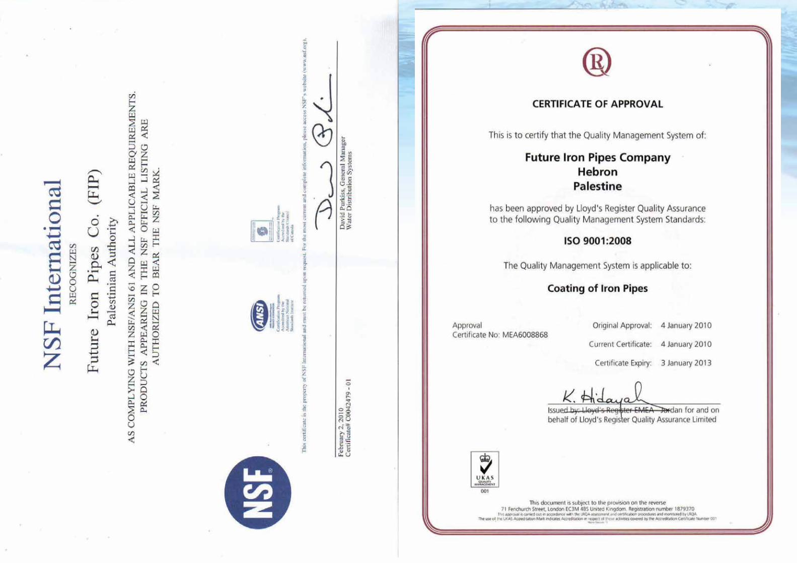
Table Of ContentsCertifications
Introduction
FIP Statement
Coating: Definition, Types, and Applications
Quality Control Procedure and Methodology
Internal cement lining
Mechanical, and Statistical Data of Steel Pipes
Installation Applications
Handling and Storage
Steel Pipe fittings
3
7
8
10
17
19
23
26
27
31
Protec t ion technology for 3LPE/PP coated steel p ipes54
Protec t ion technology for 3LPE/PP coated steel p ipes76
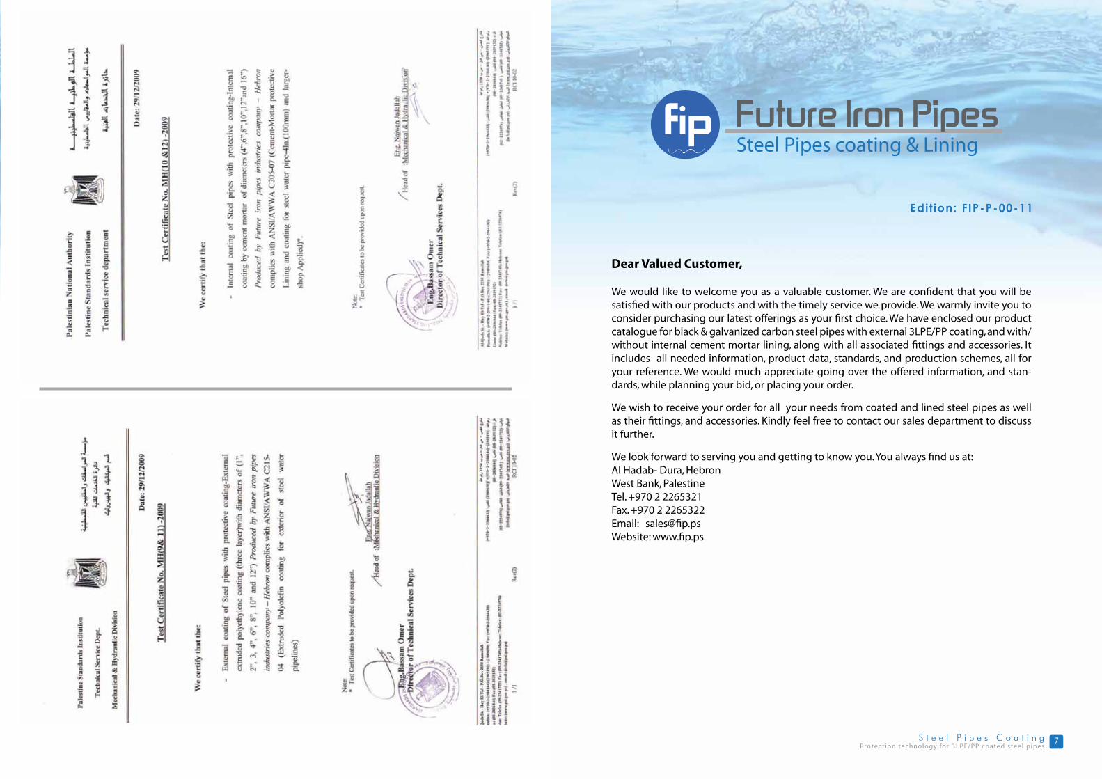
Dear Valued Customer,
We would like to welcome you as a valuable customer. We are confident that you will be satisfied with our products and with the timely service we provide. We warmly invite you to consider purchasing our latest offerings as your first choice. We have enclosed our product catalogue for black & galvanized carbon steel pipes with external 3LPE/PP coating, and with/without internal cement mortar lining, along with all associated fittings and accessories. It includes all needed information, product data, standards, and production schemes, all for your reference. We would much appreciate going over the offered information, and stan-dards, while planning your bid, or placing your order.
We wish to receive your order for all your needs from coated and lined steel pipes as well as their fittings, and accessories. Kindly feel free to contact our sales department to discuss it further.
We look forward to serving you and getting to know you. You always find us at:Al Hadab- Dura, HebronWest Bank, PalestineTel. +970 2 2265321Fax. +970 2 2265322Email: [email protected]: www.fip.ps
Edit ion: FIP-P-00-11
Protec t ion technology for 3LPE/PP coated steel p ipes98
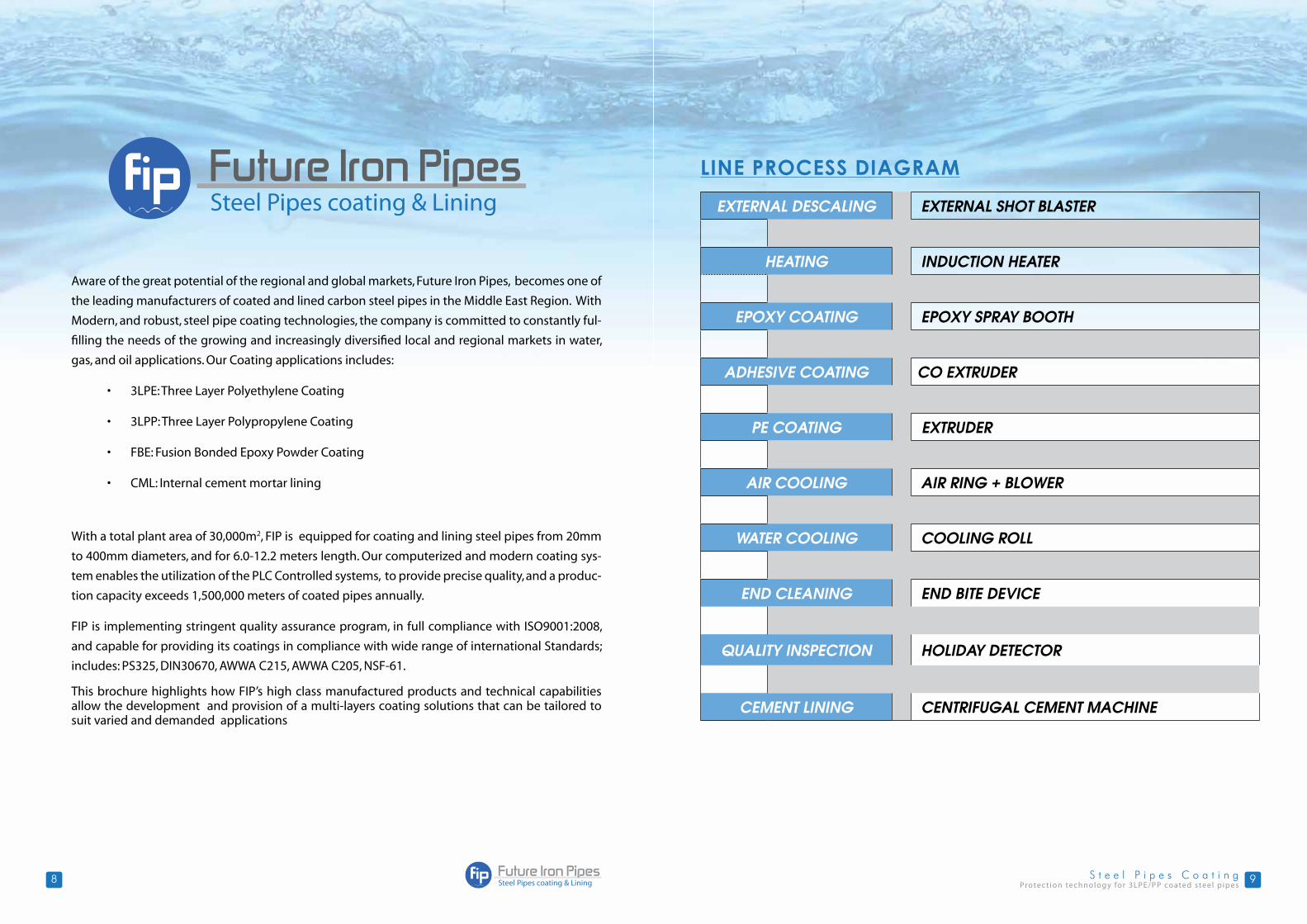
LINE PROCESS DIAGRAM
EXTERNAL DESCALING EXTERNAL SHOT BLASTER
HEATING INDUCTION HEATER
EPOXY COATING EPOXY SPRAY BOOTH
ADHESIVE COATING CO EXTRUDER
PE COATING EXTRUDER
AIR COOLING AIR RING + BLOWER
WATER COOLING COOLING ROLL
END CLEANING END BITE DEVICE
QUALITY INSPECTION HOLIDAY DETECTOR
CEMENT LINING CENTRIFUGAL CEMENT MACHINE
Aware of the great potential of the regional and global markets, Future Iron Pipes, becomes one of
the leading manufacturers of coated and lined carbon steel pipes in the Middle East Region. With
Modern, and robust, steel pipe coating technologies, the company is committed to constantly ful-
filling the needs of the growing and increasingly diversified local and regional markets in water,
gas, and oil applications. Our Coating applications includes:
• 3LPE: Three Layer Polyethylene Coating
• 3LPP: Three Layer Polypropylene Coating
• FBE: Fusion Bonded Epoxy Powder Coating
• CML: Internal cement mortar lining
With a total plant area of 30,000m2, FIP is equipped for coating and lining steel pipes from 20mm
to 400mm diameters, and for 6.0-12.2 meters length. Our computerized and modern coating sys-
tem enables the utilization of the PLC Controlled systems, to provide precise quality, and a produc-
tion capacity exceeds 1,500,000 meters of coated pipes annually.
FIP is implementing stringent quality assurance program, in full compliance with ISO9001:2008,
and capable for providing its coatings in compliance with wide range of international Standards;
includes: PS325, DIN30670, AWWA C215, AWWA C205, NSF-61.
This brochure highlights how FIP’s high class manufactured products and technical capabilities allow the development and provision of a multi-layers coating solutions that can be tailored to suit varied and demanded applications

Protec t ion technology for 3LPE/PP coated steel p ipes1110
Coating: Definition, Types, and Applications
Definition
The 3-layered Polyethylene (3LPE) is a multilayer, thermoplastic coating designed to provide maximum long term corrosion resistance and mechanical protection to steel pipes. This Technology has the advantages of superior adhesion, cathodic disbondment and impact resistance, where these properties are essential for maintaining pipeline integrity, and durability.
Types of Coating:
• 3LPE( 3 layered polyethylene coating
• Fusion Bonded Epoxy (FBE)
• Internal lining
Advantages of 3LPE coating in general
1- High Corrosion Protection The 3LPE coating composition guarantees extreme adhesion property of the PE to the steel pipes
which ensures no corrosion to the steel and also high resistance to cathodic dispondment in the field.
2- Flexibility of production The flexibility of the 3LPE coating technology gives the ability to apply the coating to steel pipes ranging from ½” to 16” with a wide range of thicknesses meeting any requested standard or customer
needs.
3- Very Good Mechanical, Physical , and Chemical Protection The strong layer of polyethylene provides high mechanical and physical strength to the steel pipes that permits it to endure all handling and transportation accidents which consumes money and time to repair, while the chemical structure of the polyethylene provides high protection from soil and wear
conditions.
Additionally the following advantages are achieved in the 3LPE Systems:
• High resistance to penetration.
• High impact strength.
• High rigidity.
• High elasticity and resistance to tearing.
• High electric insulation.
• High resistance to chemicals and
oxidization
• Withstand high temperatures ; PE resists
up to 70oC, while PP resists up to 110oC
Protec t ion technology for 3LPE/PP coated steel p ipes1312
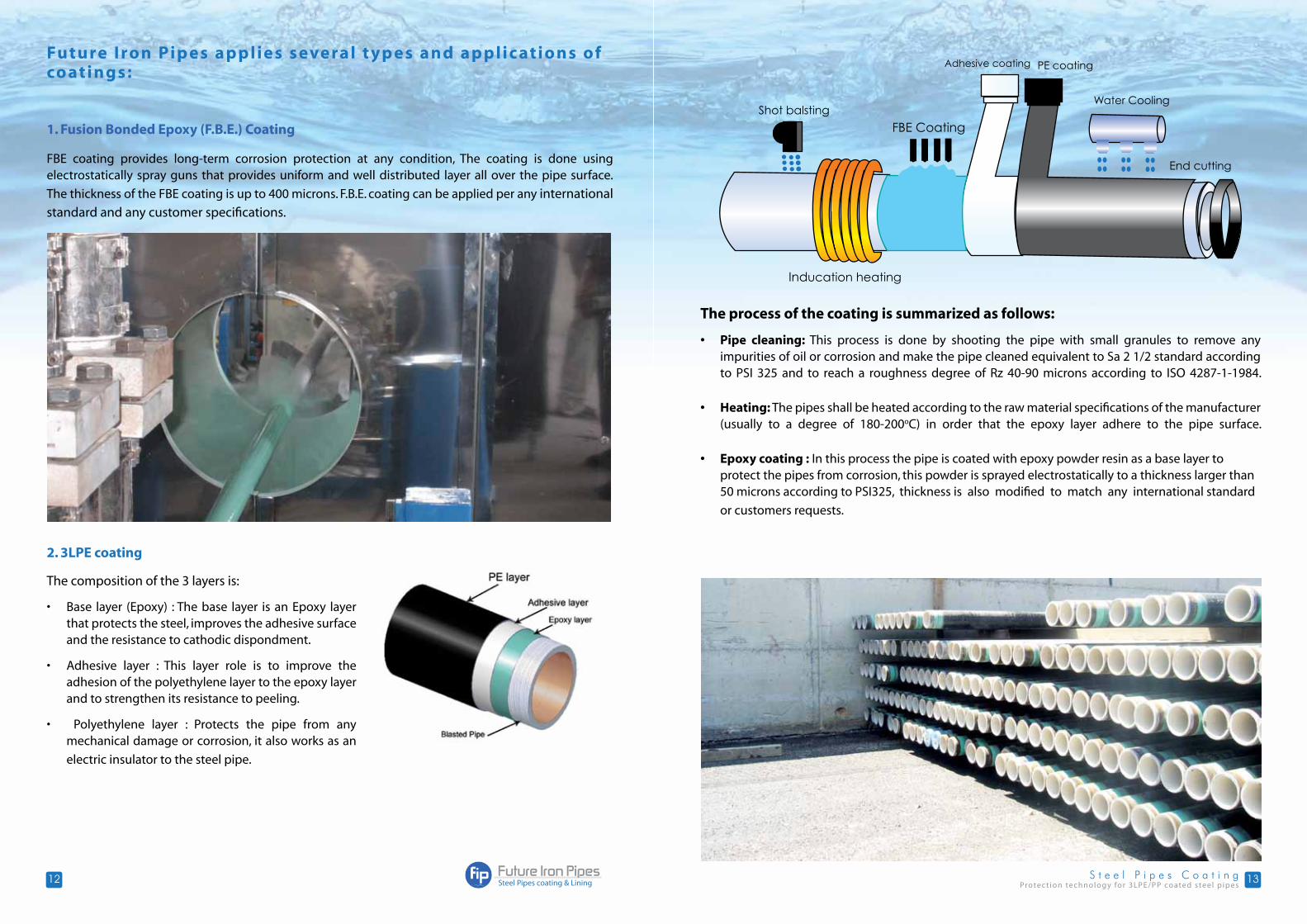
Future Iron Pip es applies several t yp es and applic ations of coatings:
1. Fusion Bonded Epoxy (F.B.E.) Coating
FBE coating provides long-term corrosion protection at any condition, The coating is done using electrostatically spray guns that provides uniform and well distributed layer all over the pipe surface.
The thickness of the FBE coating is up to 400 microns. F.B.E. coating can be applied per any international
standard and any customer specifications.
2. 3LPE coating
The composition of the 3 layers is:
• Base layer (Epoxy) : The base layer is an Epoxy layer that protects the steel, improves the adhesive surface and the resistance to cathodic dispondment.
• Adhesive layer : This layer role is to improve the adhesion of the polyethylene layer to the epoxy layer and to strengthen its resistance to peeling.
• Polyethylene layer : Protects the pipe from any mechanical damage or corrosion, it also works as an
electric insulator to the steel pipe.
The process of the coating is summarized as follows:
• Pipe cleaning: This process is done by shooting the pipe with small granules to remove any impurities of oil or corrosion and make the pipe cleaned equivalent to Sa 2 1/2 standard according to PSI 325 and to reach a roughness degree of Rz 40-90 microns according to ISO 4287-1-1984.
• Heating: The pipes shall be heated according to the raw material specifications of the manufacturer (usually to a degree of 180-200oC) in order that the epoxy layer adhere to the pipe surface.
• Epoxy coating : In this process the pipe is coated with epoxy powder resin as a base layer to protect the pipes from corrosion, this powder is sprayed electrostatically to a thickness larger than 50 microns according to PSI325, thickness is also modified to match any international standard
or customers requests.
Protec t ion technology for 3LPE/PP coated steel p ipes1514
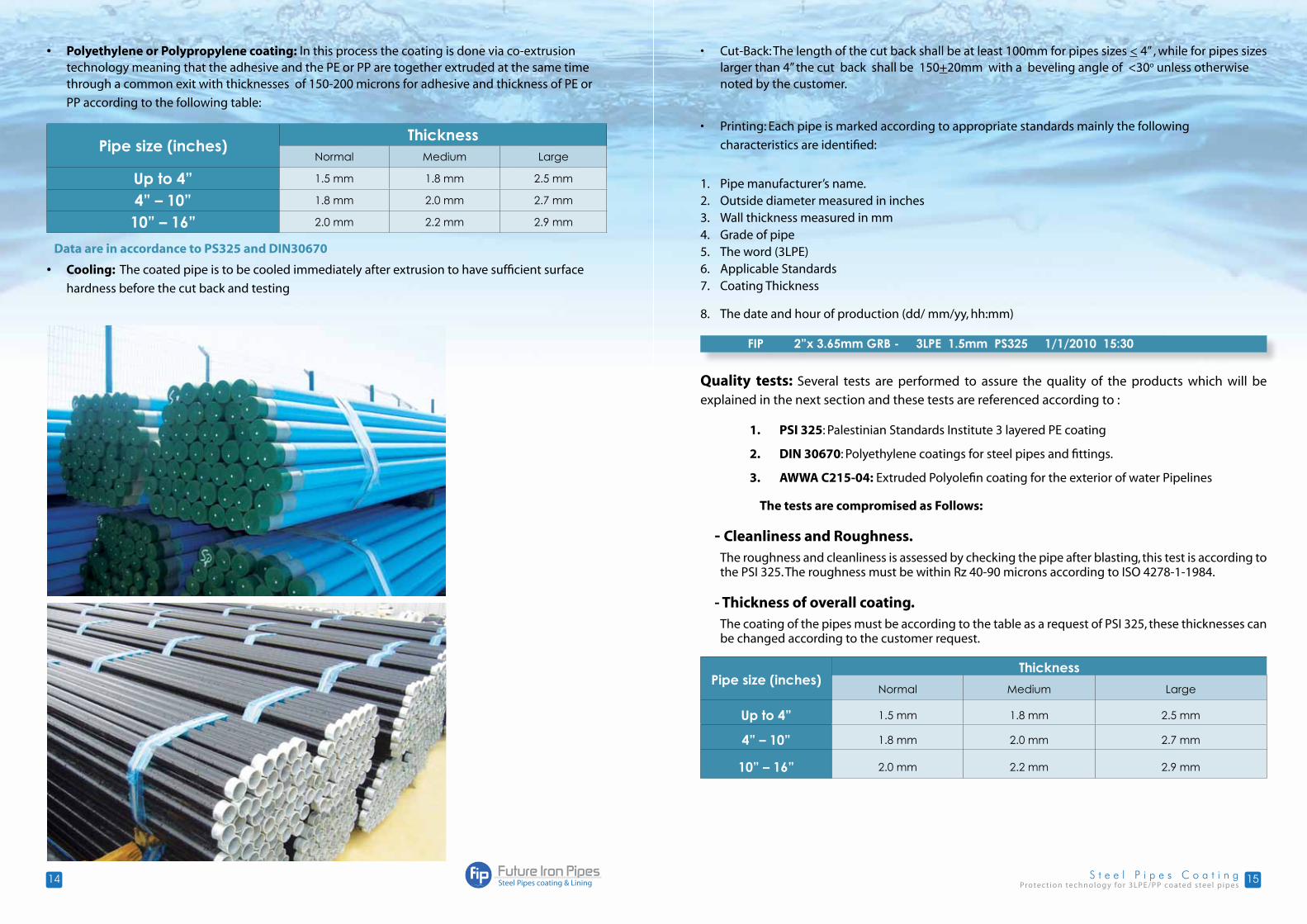
• Polyethylene or Polypropylene coating: In this process the coating is done via co-extrusion technology meaning that the adhesive and the PE or PP are together extruded at the same time through a common exit with thicknesses of 150-200 microns for adhesive and thickness of PE or
PP according to the following table:
Pipe size (inches)Thickness
Normal Medium Large
Up to 4” 1.5 mm 1.8 mm 2.5 mm
4” – 10” 1.8 mm 2.0 mm 2.7 mm
10” – 16” 2.0 mm 2.2 mm 2.9 mm
• Cooling: The coated pipe is to be cooled immediately after extrusion to have sufficient surface
hardness before the cut back and testing
• Cut-Back: The length of the cut back shall be at least 100mm for pipes sizes < 4” , while for pipes sizes larger than 4” the cut back shall be 150+20mm with a beveling angle of <30o unless otherwise noted by the customer.
• Printing: Each pipe is marked according to appropriate standards mainly the following
characteristics are identified:
1. Pipe manufacturer’s name.2. Outside diameter measured in inches3. Wall thickness measured in mm4. Grade of pipe5. The word (3LPE)6. Applicable Standards7. Coating Thickness
8. The date and hour of production (dd/ mm/yy, hh:mm)
Quality tests: Several tests are performed to assure the quality of the products which will be
explained in the next section and these tests are referenced according to :
1. PSI 325: Palestinian Standards Institute 3 layered PE coating
2. DIN 30670: Polyethylene coatings for steel pipes and fittings.
3. AWWA C215-04: Extruded Polyolefin coating for the exterior of water Pipelines
The tests are compromised as Follows:
- Cleanliness and Roughness.The roughness and cleanliness is assessed by checking the pipe after blasting, this test is according to the PSI 325. The roughness must be within Rz 40-90 microns according to ISO 4278-1-1984.
- Thickness of overall coating.The coating of the pipes must be according to the table as a request of PSI 325, these thicknesses can be changed according to the customer request.
Pipe size (inches)Thickness
Normal Medium Large
Up to 4” 1.5 mm 1.8 mm 2.5 mm
4” – 10” 1.8 mm 2.0 mm 2.7 mm
10” – 16” 2.0 mm 2.2 mm 2.9 mm
FIP 2”x 3.65mm GRB - 3LPE 1.5mm PS325 1/1/2010 15:30
Data are in accordance to PS325 and DIN30670
Protec t ion technology for 3LPE/PP coated steel p ipes1716
- Coating continuity.The test is done via a holiday detector that detects any porosity in the coating, for each millimeter10 kV are applied to the coating on a condition that the voltage doesn’t exceed 25 kV according to PSI 325.
- Peeling testThis test is done after 24 hours of the coating according to DIN 30 670 and PSI 325 and the average required force to remove the coating must be according to the following table
Coating type Test at 23 + 3 oC Test at 50 + 5 oC3LPE 80 N/10mm 25 N/10mm
- Indentation (impact) testThe impact test is done by dropping a weight with a 25 mm diameter ball head from an elevation of one meter on several points and the energy produced must be as shown in the following table:
Nominal pipe diameter Impact energy per mm of coating thicknessLess than 2.5”From 2.5”- 8”
Above 8”
3.5 J4.3 J5.0 J
Then the continuity test is done to ensure that there are no holes or penetrations in the coating
according to PSI 325.
- Penetration assessmentAccording to the DIN 30 670 the penetration depth must not exceed 0.2 mm at a temperature of 23 + 2 oC and 0.3 mm at a temperature 50 + 2 oC .
- Elongation at break point. This test is done according to PSI 99 part 3. In this test a pipe is coated without adhesive layer and then the elongation of the specimen is measured at the breaking, the shape and dimensions of the specimen must be according to model A of the standard, the tension speed must be 25 mm/min and the elongation ratio at the break point must be 350%.
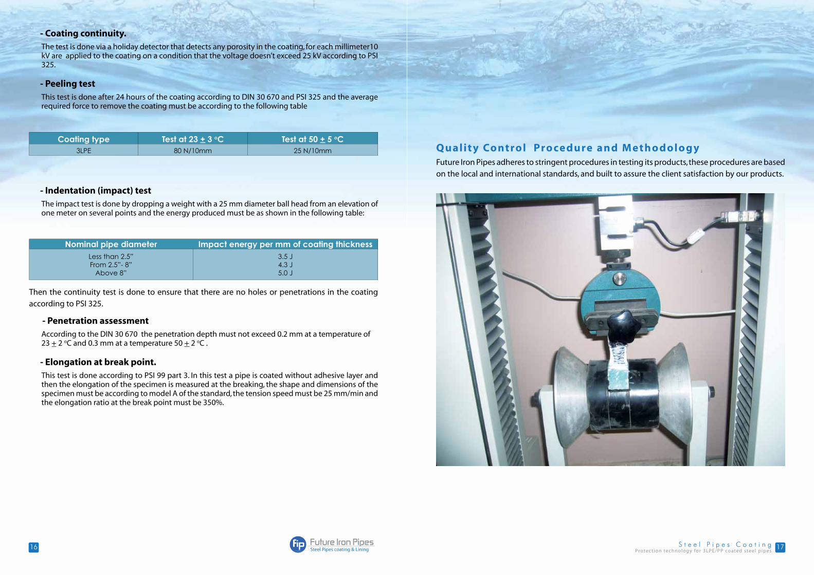
Q ualit y Control Pro cedure and M etho dolo gy Future Iron Pipes adheres to stringent procedures in testing its products, these procedures are based
on the local and international standards, and built to assure the client satisfaction by our products.
Protec t ion technology for 3LPE/PP coated steel p ipes1918
Properties Method of Test MinimumProduction Control
Pipe Surface Visual every pipe
blast cleaning and Roughness
Using special measuring devices
twice per shift
Surface preparation Visual 100% inspection
Pipe temperature after induction heating
Heat sensor continuously
Appearance and continuity Visual every pipe
Coating Thickness testing According to standards twice per shift
Cut back Visual every pipe
Holiday inspection According to standards 100% of all pipes
Impact resistance According to standards one per order
Adhesion (Peeling resistance) test
According to standardson one pipe each100 coated pipes
Indentation test According to standards one by order
Elongation test According to standards Raw material change
Our Quality control plan is summrized as :
Introduction about the industry
The internal cement mortar lining provides protection to the pipeline in two ways. First, it is a “cement pipe within a steel pipe”, and second, by creating a “Zone of Alkalinity”. This “zone” between the cement lining and the pipe wall, neutralizes the corrosive properties of the liquid medium and blocks corrosion of the pipe wall. In effect, the “Zone of Alkalinity” serves as a second layer of defense against internal corrosion. Unlike other types of internal linings, which allow pipe corrosion to spread down the line once they are chipped or damaged in any spot, the cement lining prevents corrosion from
spreading along the pipe wall.
Manufacturing Process
The lining is applied by using a high-speed centrifugal process. By using this method, excellent quality control of the cement-mortar lining is maintained. The cement linings FIP produces are dense, smooth, uniform, well bonded to the pipe wall, and offer very little frictional resistance to the flow of water.
The pipe is spun at a very high rate accompanied by vibration to produce a dense lining. This high-speed lining brings water and latence to the lining surface. The latence is immediately washed out of the pipe with water. The immediate result is a smooth, dense, and well-compacted cement-mortar lining.
After the application process, the linings are then cured by sealing the pipes ends for 5 days to prevent too rapid loss of moisture from the mortar. The process of lining the cement internally is summarized
as follows:
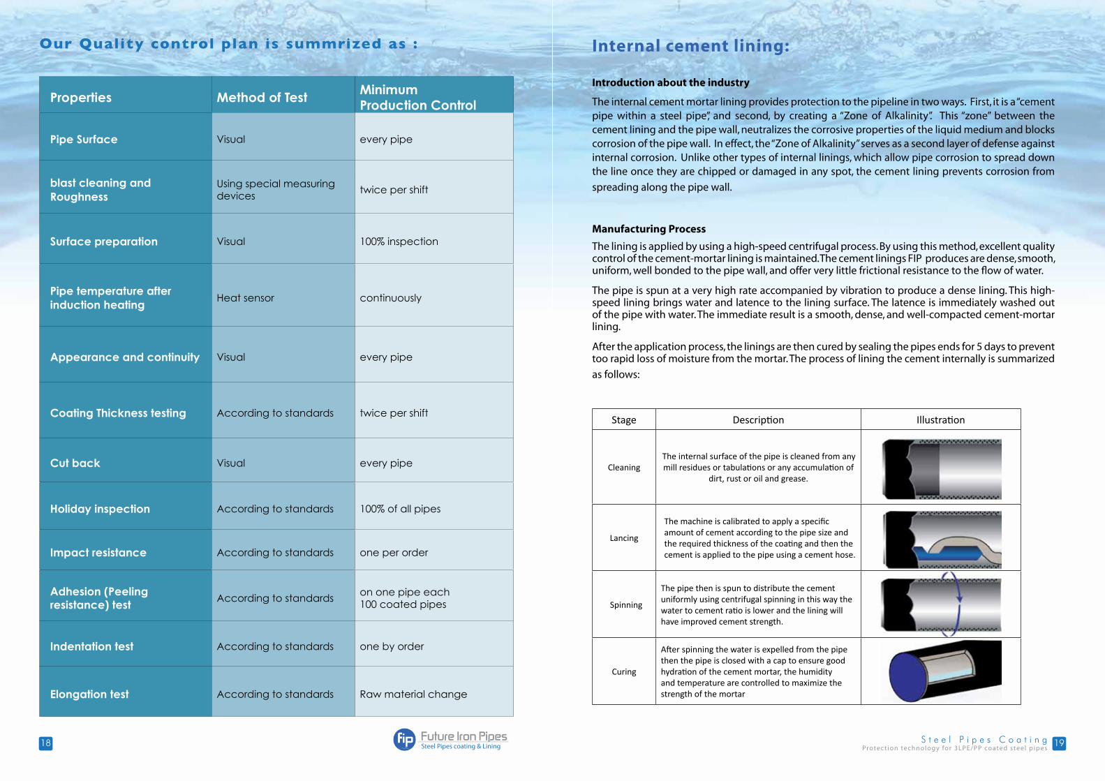
Stage Description Illustration
CleaningThe internal surface of the pipe is cleaned from any mill residues or tabulations or any accumulation of
dirt, rust or oil and grease.
Lancing
The machine is calibrated to apply a specific amount of cement according to the pipe size and the required thickness of the coating and then the cement is applied to the pipe using a cement hose.
Spinning
The pipe then is spun to distribute the cement uniformly using centrifugal spinning in this way the water to cement ratio is lower and the lining will have improved cement strength.
Curing
After spinning the water is expelled from the pipe then the pipe is closed with a cap to ensure good hydration of the cement mortar, the humidity and temperature are controlled to maximize the strength of the mortar
Internal cement lining:
Protec t ion technology for 3LPE/PP coated steel p ipes2120
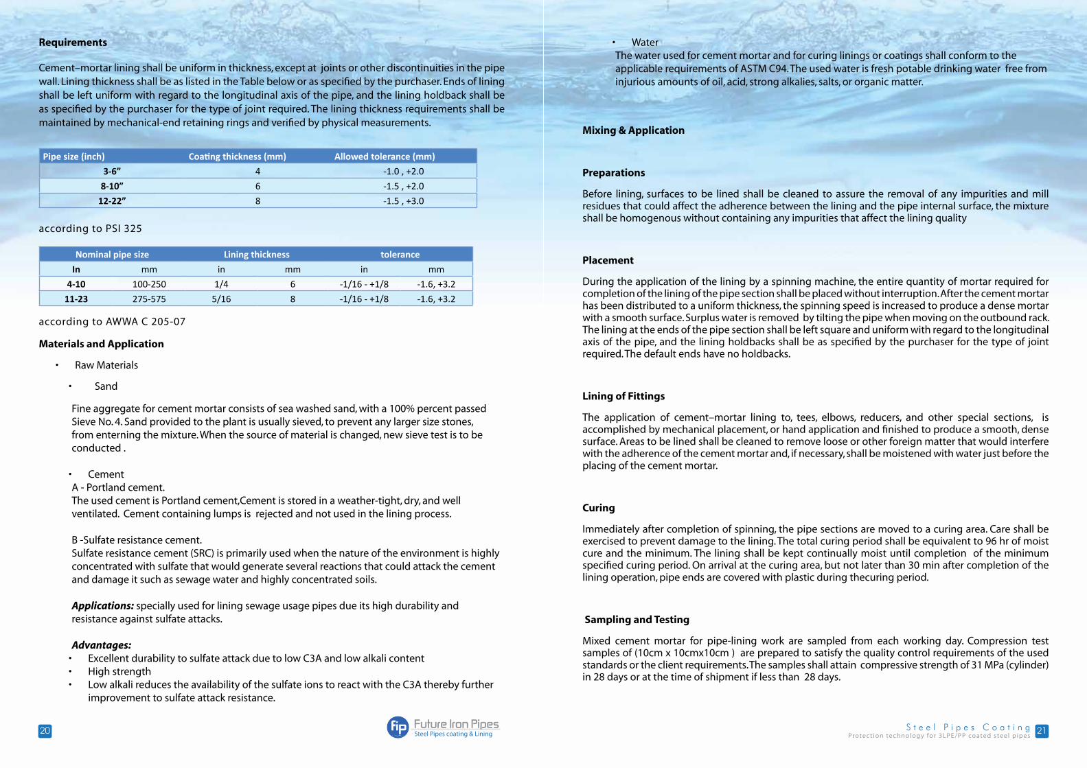
Requirements
Cement–mortar lining shall be uniform in thickness, except at joints or other discontinuities in the pipe wall. Lining thickness shall be as listed in the Table below or as specified by the purchaser. Ends of lining shall be left uniform with regard to the longitudinal axis of the pipe, and the lining holdback shall be as specified by the purchaser for the type of joint required. The lining thickness requirements shall be maintained by mechanical-end retaining rings and verified by physical measurements.
Pipe size (inch) Coating thickness (mm) Allowed tolerance (mm)
3-6” 4 -1.0 , +2.0
8-10” 6 -1.5 , +2.0
12-22” 8 -1.5 , +3.0
according to PSI 325
Nominal pipe size Lining thickness tolerance
In mm in mm in mm
4-10 100-250 1/4 6 -1/16 - +1/8 -1.6, +3.2
11-23 275-575 5/16 8 -1/16 - +1/8 -1.6, +3.2
according to AWWA C 205-07
Materials and Application
• Raw Materials
• Sand
Fine aggregate for cement mortar consists of sea washed sand, with a 100% percent passed Sieve No. 4. Sand provided to the plant is usually sieved, to prevent any larger size stones, from enterning the mixture. When the source of material is changed, new sieve test is to be conducted .
• Cement A - Portland cement.The used cement is Portland cement,Cement is stored in a weather-tight, dry, and well ventilated. Cement containing lumps is rejected and not used in the lining process.
B -Sulfate resistance cement.Sulfate resistance cement (SRC) is primarily used when the nature of the environment is highly concentrated with sulfate that would generate several reactions that could attack the cement and damage it such as sewage water and highly concentrated soils.
Applications: specially used for lining sewage usage pipes due its high durability and resistance against sulfate attacks.
Advantages:• Excellent durability to sulfate attack due to low C3A and low alkali content• High strength• Low alkali reduces the availability of the sulfate ions to react with the C3A thereby further
improvement to sulfate attack resistance.
Mixing & Application
Preparations
Before lining, surfaces to be lined shall be cleaned to assure the removal of any impurities and mill residues that could affect the adherence between the lining and the pipe internal surface, the mixture shall be homogenous without containing any impurities that affect the lining quality
Placement
During the application of the lining by a spinning machine, the entire quantity of mortar required for completion of the lining of the pipe section shall be placed without interruption. After the cement mortar has been distributed to a uniform thickness, the spinning speed is increased to produce a dense mortar with a smooth surface. Surplus water is removed by tilting the pipe when moving on the outbound rack. The lining at the ends of the pipe section shall be left square and uniform with regard to the longitudinal axis of the pipe, and the lining holdbacks shall be as specified by the purchaser for the type of joint required. The default ends have no holdbacks.
Lining of Fittings
The application of cement–mortar lining to, tees, elbows, reducers, and other special sections, is accomplished by mechanical placement, or hand application and finished to produce a smooth, dense surface. Areas to be lined shall be cleaned to remove loose or other foreign matter that would interfere with the adherence of the cement mortar and, if necessary, shall be moistened with water just before the placing of the cement mortar.
Curing
Immediately after completion of spinning, the pipe sections are moved to a curing area. Care shall be exercised to prevent damage to the lining. The total curing period shall be equivalent to 96 hr of moist cure and the minimum. The lining shall be kept continually moist until completion of the minimum specified curing period. On arrival at the curing area, but not later than 30 min after completion of the lining operation, pipe ends are covered with plastic during thecuring period.
Sampling and Testing
Mixed cement mortar for pipe-lining work are sampled from each working day. Compression test samples of (10cm x 10cmx10cm ) are prepared to satisfy the quality control requirements of the used standards or the client requirements. The samples shall attain compressive strength of 31 MPa (cylinder) in 28 days or at the time of shipment if less than 28 days.
• WaterThe water used for cement mortar and for curing linings or coatings shall conform to the applicable requirements of ASTM C94. The used water is fresh potable drinking water free from injurious amounts of oil, acid, strong alkalies, salts, or organic matter.

Protec t ion technology for 3LPE/PP coated steel p ipes2322
Repair
Lining repair
Defects, including but not restricted to sand pockets, voids, over sanded areas, blisters, and cracking as a result of impacts, shall be removed and replaced by hand or pneumatic placement to the same thickness as required for the cement–mortar lining.
Lining Cracks
Temperature and shrinkage cracks in the cement–mortar lining less than 1/16 in. (1.6 mm) in width need not be repaired , since they autogenously repaired under continuous soaking in water. Cracks wider than 1/16 in. (1.6 mm) shall be repaired by applying cement water grout, and spin the pipe to insure that the cracks are filled with the grout.
Special Concerns
The purchaser of cement–mortar linings is cautioned about the following concerns:
• Soft, aggressive waters. Soft, aggressive waters, as well as prolonged contact with heavily chlorinated water, may be injurious to cement–mortar linings. When this environment is anticipated, further studies may be necessary to determine the suitability of this type of lining.
• Flow velocity. Cement–mortar linings perform best when flow velocities are in normal ranges. When the flow velocity exceeds approximately 6.1 m/sec, special studies may be required to determine the suitability of this type of lining material.
• Health Effects: Compliance with NSF/ANSI 61, or relevant health standards for Drinking Water System Components is necessary, and shall be confirmed.
Reference Standards
This statement is built on the following 2 Standards:
• AWWA C205-7
• PSI 325
Me
ch
an
ica
l, a
nd
Sta
tisti
ca
l D
ata
of
Ste
el
Pip
es:
•G
alv
an
ize
d
Pip
es
Nom
inal
Dia
met
erO
f pip
e (in
)
Exte
rnal
Dia
met
erO
f pip
e(m
m)
Inte
rnal
Dia
met
erO
f pi
pe(m
m)
Wal
lth
ickn
ess
Blac
k pi
pew
eigh
tCo
ated
Are
a m
2 /mG
alva
nize
dPi
pe w
eigh
t kg/
m
Gal
vani
zed
Coat
ed p
ipe
wei
ght k
g/m
GRB mm
SCH
40 m
m
GRB mm
SCH
40
mm
GRB
Kg/m
Sch. 40
Kg/m
Gra
de B
Sch. 40
GRB
Sch. 40
GRB
Sch. 40
ext
int
ext
int
1/2
21.3
1615
.76
2.65
2.77
1.22
1.27
0.06
70.
050.
067
0.05
1.28
1.33
1.36
1.41
3/4
26.7
21.4
20.9
62.
652.
871.
581.
690.
084
0.06
70.
084
0.06
71.
661.
751.
771.
86
133
.426
.926
.64
3.25
3.38
2.44
2.5
0.10
50.
084
0.10
50.
084
2.54
2.60
2.67
2.73
1 1/
442
.235
.735
.08
3.25
3.56
3.14
3.39
0.13
30.
112
0.13
30.
110
3.26
3.51
3.43
3.68
1 1/
248
.341
.840
.94
3.25
3.68
3.61
4.05
0.15
20.
131
0.15
20.
128
3.75
4.19
3.94
4.38
260
.353
52.4
83.
653.
915.
105.
440.
189
0.16
60.
189
0.16
55.
285.
625.
525.
86
Protec t ion technology for 3LPE/PP coated steel p ipes2524
Me
ch
an
ica
l, a
nd
Sta
tisti
ca
l D
ata
of
Ste
el
Pip
es:
Bla
ck
Ste
el
Pip
es
•M
ec
ha
nic
al,
an
d S
tati
sti
ca
l D
ata
of
Ste
el
Pip
es:
•B
lac
k S
tee
l P
ipe
s
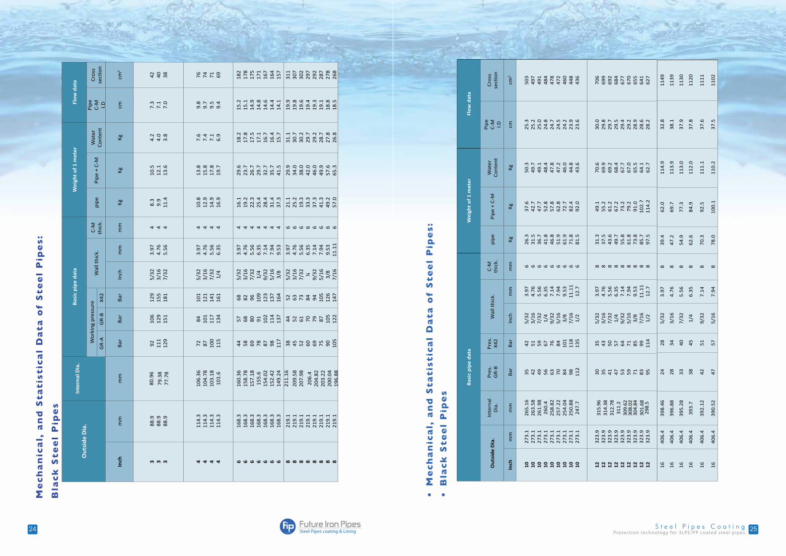
Ou
tsid
e D
ia.
Inte
rnal
Dia
.B
asic
pip
e d
ata
Wei
ght
of
1 m
eter
Flo
w d
ata
Wor
king
pre
ssur
eW
all t
hick
.C
-M
thic
k.pi
pePi
pe +
C-M
W
ater
Con
tent
Pipe
C-M I.D
Cro
ssse
ction
GR
-AG
R-B
X42
Inch
mm
mm
Bar
Bar
Bar
Inch
mm
mm
KgKg
Kgcm
cm2
3 3 3
88.9
88.9
88.9
80.9
6
79.3
877
.78
92 111
129
106
129
151
129
155
181
5/32
3/16
7/32
3.97
4.76
5.56
4 4 4
8.3
9.9
11.4
10.5
12.1
13.6
4.2
4.0
3.8
7.3
7.1
7.0
42 40 38
4 4 4 4
114.
311
4.3
114.
311
4.3
106.
3610
4.78
103.
1810
1.6
72 87 100
115
84 101
117
134
101
121
141
161
5/32
3/16
7/32
1/4
3.97
4.76
5.56
6.35
4 4 4 4
10.8
12.9
14.9
16.9
13.8
15.8
17.8
19.7
7.6
7.4
7.1
6.9
9.8
9.7
9.5
9.4
76 74 71 69
6 6 6 6 6 6 6
168.
316
8.3
168.
316
8.3
168.
316
8.3
168.
3
160.
3615
8.78
157.
1815
5.6
154.
0215
2.42
149.
24
44 58 69 78 87 98 117
57 68 80 91 102
114
137
68 82 96 109
123
137
164
5/32
3/16
7/32
1/4
9/32
5/16
3/8
3.97
4.76
5.56
6.35
7.14
7.94
9.53
4 4 4 4 4 4 4
16.1
19.2
22.3
25.4
28.4
31.4
37.3
29.6
23.7
26.7
29.7
32.7
35.7
41.5
18.2
17.8
17.5
17.1
16.7
16.4
15.7
15.2
15.1
14.9
14.8
14.6
14.4
14.1
182
178
175
171
167
164
157
8 8 8 8 8 8 8 8
219.
121
9.1
219.
121
9.1
219.
121
9.1
219.
121
9.1
211.
16
209.
5820
7.98
206.
420
4.82
203.
2220
0.04
196.
88
38 45 52 60 69 75 90 105
44 52 61 70 79 87 105
122
52 63 73 84 94 105
126
147
5/32
3/16
7/32 ¼
9/32
5/16
3/8
7/16
3.97
4.76
5.56
6.35
7.14
7.94
9.53
11.1
1
6 6 6 6 6 6 6 6
21.1
25.2
19.3
33.3
37.3
41.3
49.2
57.0
29.9
34.0
38.0
42.0
46.0
49.9
57.6
65.3
31.1
30.7
30.2
29.7
29.2
28.7
27.8
26.8
19.9
19.8
19.6
19.4
19.3
19.1
18.8
18.5
311
307
302
297
292
287
278
268
Bas
ic p
ipe
dat
aW
eigh
t o
f 1
met
erFl
ow
dat
a
Ou
tsid
e D
ia.
Inte
rnal
D
ia.
Pre
s.G
R-B
Pre
s.X
42W
all t
hic
k.C
-M
thic
k.p
ipe
Pip
e +
C-M
W
ater
Co
nte
nt
Pip
eC
-M I.D
Cro
ssse
ctio
n
Inch
mm
mm
Bar
Bar
Inch
mm
mm
Kg
Kg
Kg
cmcm
2
10
10
10
10
10
10
10
10
10
273.
127
3.1
273.
127
3.1
273.
127
3.1
273.
127
3.1
273.
1
265.
1626
3.58
261.
9826
0.4
258.
8225
7.22
254.
0425
0.88
247.
7
35 42 49 56 63 70 84 98 112
42 51 59 67 76 84 101
118
135
5/32
3/16
7/32
1/4
9/32
5/16
3/8
7/16
1/2
3.97
4.76
5.56
6.35
7.14
7.94
9.53
11.1
112
.7
6 6 6 6 6 6 6 6 6
26.3
31.5
36.7
41.8
46.8
51.9
61.9
71.8
81.5
37.6
42.7
47.7
52.8
57.8
62.8
72.7
82.4
92.0
50.3
49.7
49.1
48.4
47.8
47.2
46.0
44.8
43.6
25.3
25.2
25.0
24.8
24.7
24.5
24.2
23.9
23.6
503
497
491
484
478
472
460
448
436
12
12
12
12
12
12
12
12
12
323.
932
3.9
323.
932
3.9
323.
932
3.9
323.
932
3.9
323.
9
315.
9631
4.38
312.
7831
1.2
309.
6230
8.02
304.
8430
1.68
298.
5
30 35 41 47 53 59 71 83 95
35 43 50 57 64 71 85 99 114
5/32
3/16
7/32
1/4
9/32
5/16
3/8
7/16
1/2
3.97
4.76
5.56
6.35
7.14
7.94
9.53
11.1
112
.7
8 8 8 8 8 8 8 8 8
31.3
37.5
43.6
49.7
55.8
61.8
73.8
85.7
97.5
49.1
55.2
61.2
67.2
73.2
79.2
91.0
102.
711
4.2
70.6
69.9
69.2
68.4
67.7
67.0
65.5
64.1
62.7
30.0
29.8
29.7
29.5
29.4
29.2
28.9
28.6
28.2
706
699
692
684
677
670
655
641
627
1640
6.4
398.
4624
285/
323.
978
39.4
62.0
114.
932
.811
49
1640
6.4
396.
8828
343/
164.
768
47.2
69.7
113.
938
.111
39
1640
6.4
395.
2833
407/
325.
568
54.9
77.3
113.
037
.911
30
1640
6.4
393.
738
451/
46.
358
62.6
84.9
112.
037
.811
20
1640
6.4
392.
1242
519/
327.
148
70.3
92.5
111.
137
.611
11
1640
6.4
390.
5247
575/
167.
948
78.0
100.
111
0.2
37.5
1102

Protec t ion technology for 3LPE/PP coated steel p ipes2726
Instal lation Applic ations
Heat shrinkable sheets: Heat shrinkable sheets are used to cover the welding
areas between any two pipes in order to make sure
that no corrosion is permitted in the area of welding
to assure full protection of pipes.
Future Iron Pipes recommends the use of these sheets
since the moisture penetration to the pipes is a very
costly issue to the water lines and a costumer can request this type of sheets at the facility
Basic installation of shrinkable sheets:• Clean the area at which a penetration has occurred with steel wire brush, including 10 cm of the
PE coated pipes ends.
• Heat the pipe with a gas burner to 70-75oC.
• Apply the shrinkable sheets and make sure to press the sheet all over the pipe while heating the
sheet and then heat the adhesive layer at the ends of the sheet.
Advantages of shrinkable sheets:• Field friendly
• No high pre-heat required
• Easy to install.
• Low cost.
Handling and storage:
A reasonable amount of care in handling the pipe should be taken during stockpiling. The necessary measures are taken to insure that the pipes will not be dropped, dragged, or bumped against other pipe or objects, or climbed on. Other items, such as, fittings, and accessories, will be stored in a convenient area away from construction traffic, protected from damage and theft. Safety precautions will be taken during jobsite storage and stockpiling. Coated pipes and fittings will be moved using a crane with a nylon sling or cushioned cable for safe handling.
Handling:
Pipes with beveled ends must be placed in an even and clean ground preventing any type of dirt or stones to contact the pipes this can be assured by using wooden stands that are covered with rubber to protect the coating from any accidental impacts.
Lifting and transporting the pipes must be done by using soft non-metallic grips that can be used to bind the pipes without damaging the coatings.
Storing:
In planning to store the pipes, it must be taken into account to store the pipes in a way that ensures avoiding any unnecessary moving to the pipes bundles, also storing the pipes away from the transportation routes is another way to protect the bundles during storing.
It’s also recommended to use thick bases to lift the pipes over the ground to protect it from moisture.
Bundles:
The use of bundles is a good way to store the produced pipes , the pipes sizes that are bundled are 1/2”,3/4”, 1” and 2” while other sizes are packed in a different manner for example a 2” bundle contains 50 pipes, also these bundles are separated with a minimum 3” distance of separation so that they do not contact each other
Protec t ion technology for 3LPE/PP coated steel p ipes2928
Lifting:
The lifting of pipes must always be horizontal to overcome any expected slippage, or failure. It’s really important not to use chains, gears or cables to lift the pipes which may cause undesired damage. Rubber or plastic coated slings are recommended for lifting the pipes
The correct place to lift the pipes bundles from is ¼ the length of the pipe from each side as in the figure
Using a Forklift:
It’s possible to use a forklift to lift the pipes but there are several considerations that must be done to assure no damages during lifting using forklifts
1- The fork surface must be wide and clean.
2- Pipes products may not be pushed with the forklift.
3- The fork surface must be covered with rubber to avoid damages during lifting
4- Place the forks of the forklift under the bundle in a way that assures balance of the bundles.
5- Calibrate the speed so that the pipes don’t roll on the forks surface.
Transporting:
The transportation may be done via trucks, trains or ships. While transporting the pipes; the following shall be insured
• Make sure that there is no abrasion between the pipes or between the pipes and the truck bars, rubber or plastic may be used to cover the bars if necessary. Bases and separators must be used as in storing the pipes to assure the stability of the pipes during transportation, fastening lines also used to tie the bundles with the truck with a minimum width of 5 cm not to damage the coating.
• Plastic cabs are used to close the ends of the pipes so that dirt or spillages do not enter the pipes (specially drinking water pipes).
• The maximum number of pipes that are permitted on truck depends on the pipes sizes as in the following table.
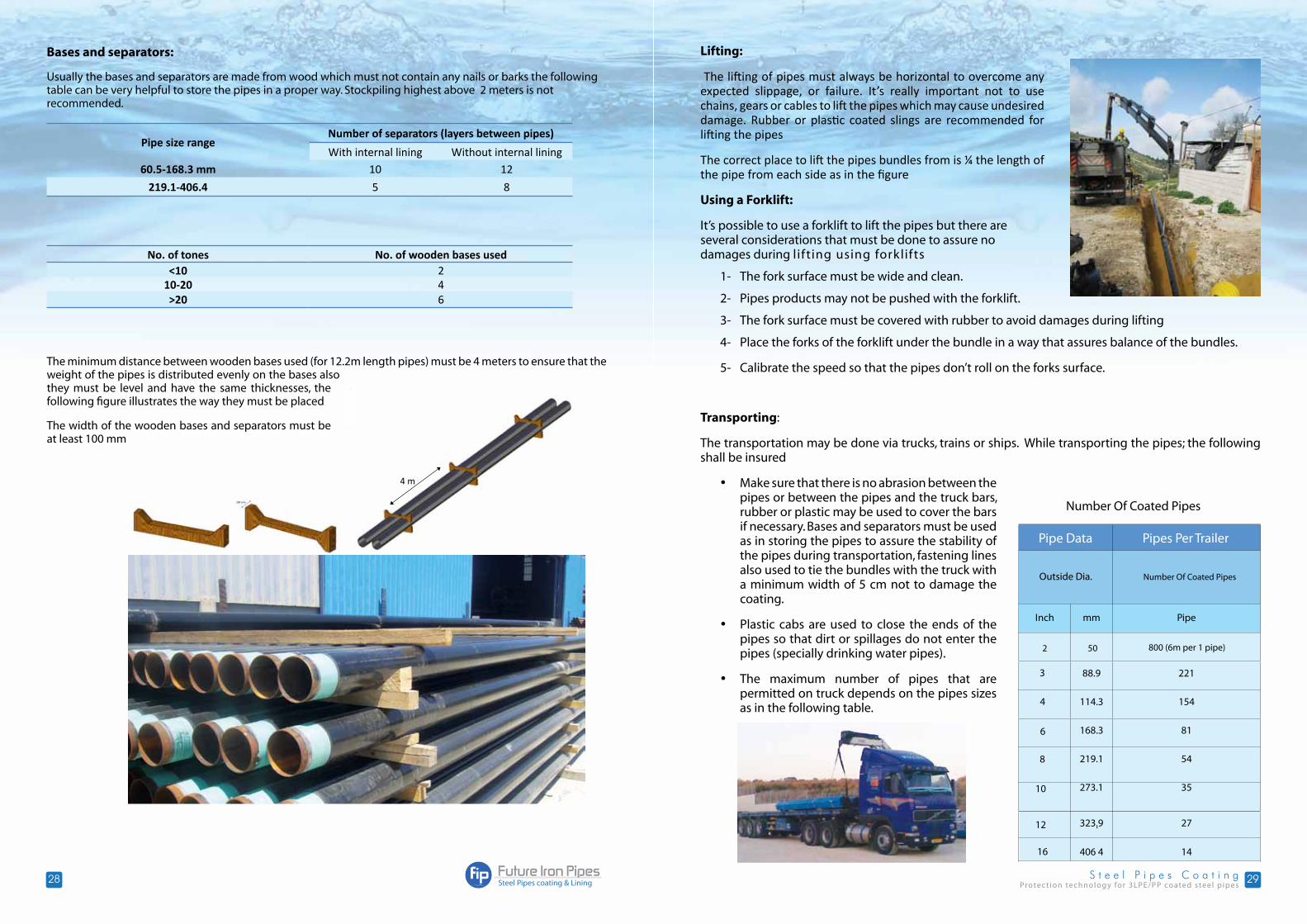
Bases and separators:
Usually the bases and separators are made from wood which must not contain any nails or barks the following table can be very helpful to store the pipes in a proper way. Stockpiling highest above 2 meters is not recommended.
Pipe size rangeNumber of separators (layers between pipes)
With internal lining Without internal lining60.5-168.3 mm 10 12
219.1-406.4 5 8
No. of tones No. of wooden bases used<10 2
10-20 4>20 6
The minimum distance between wooden bases used (for 12.2m length pipes) must be 4 meters to ensure that the weight of the pipes is distributed evenly on the bases also they must be level and have the same thicknesses, the following figure illustrates the way they must be placed
The width of the wooden bases and separators must be at least 100 mm

Protec t ion technology for 3LPE/PP coated steel p ipes3130
Instructions to unloading personnel when arriving at the delivery site:
1. Make sure truck is parked on level ground. If not, have driver move truck to a level area. Engage hand brakes and chock wheels.
2. People not involved in the unloading of the trailer and the truck driver should remain clear of the unloading area.
3. The trucker’s chains or straps should be removed from the load only after checking that the load has not shifted and will remain stable. Use caution straightening shifted loads.
4. Get sure that the forklift have a capacity rating sufficient to handle the load.5. To prevent possible injury or damage, the forks should slowly enter the pack between the top
and bottom boards of the pallet. 6. Steel bands used for packing elbows, tees, and other fittings should not be removed until the Pallet have been transported to the storage area and secured in a stable and safe manner. 7. Avoid unnecessary standing on the load. Do not remain on the load during unloading operations!
8. Do NoT USE BACkHoES, END LoADERS, oR oTHER HANDLINg EQUIPMENT To PUSH oR PULL THE LoAD oFF THE TRAILER. THIS IS DANgERoUS To UNLoADINg PERSoNNEL AND MAy DAMAgE THE PIPES, AND/oR THEIR CoATINg.
Steel Pip es f itt ingsFuture Iron Pipes company provides system accessories; including elbows, tees, flanges, designed and manufactured to meet the client requirements. Fittings are internally lined with cement mortar.
90° Elbows Butt WeldLong Radius
Nominal Size (in)
Outside Diameter (mm)
Wall thickness (T) Center to End (A)SCH. 5S SCH 10S
STDSch. 40S
XSSch. 80S
3 88.90 2.11 3.05 5.49 7.62 114.3 4 114.30 2.11 3.05 6.02 8.56 152.4 6 168.27 2.77 3.40 7.11 10.97 228.60 8 219.08 2.77 3.796 8.18 12.7 304.80
10 273.05 3.40 4.19 9.27 12.70 381.00 12 323.85 3.96 4.57 9.53 12.70 457.20 14 355.60 4.78 7.92 9.53 12.70 533.40 16 406.40 4.78 7.92 9.53 12.70 609.60
ASME/ASTM SA/A 403 WPS (Seamless) ANSI B-16-9ASME/ASTM SA/A 403 WPW (Welded) ANSI B16-9ASME/ASTM SA/A 403 WPWX (Welded/100% x Ray) ANSI B16-9Dimensions: (mm)
Protec t ion technology for 3LPE/PP coated steel p ipes3332
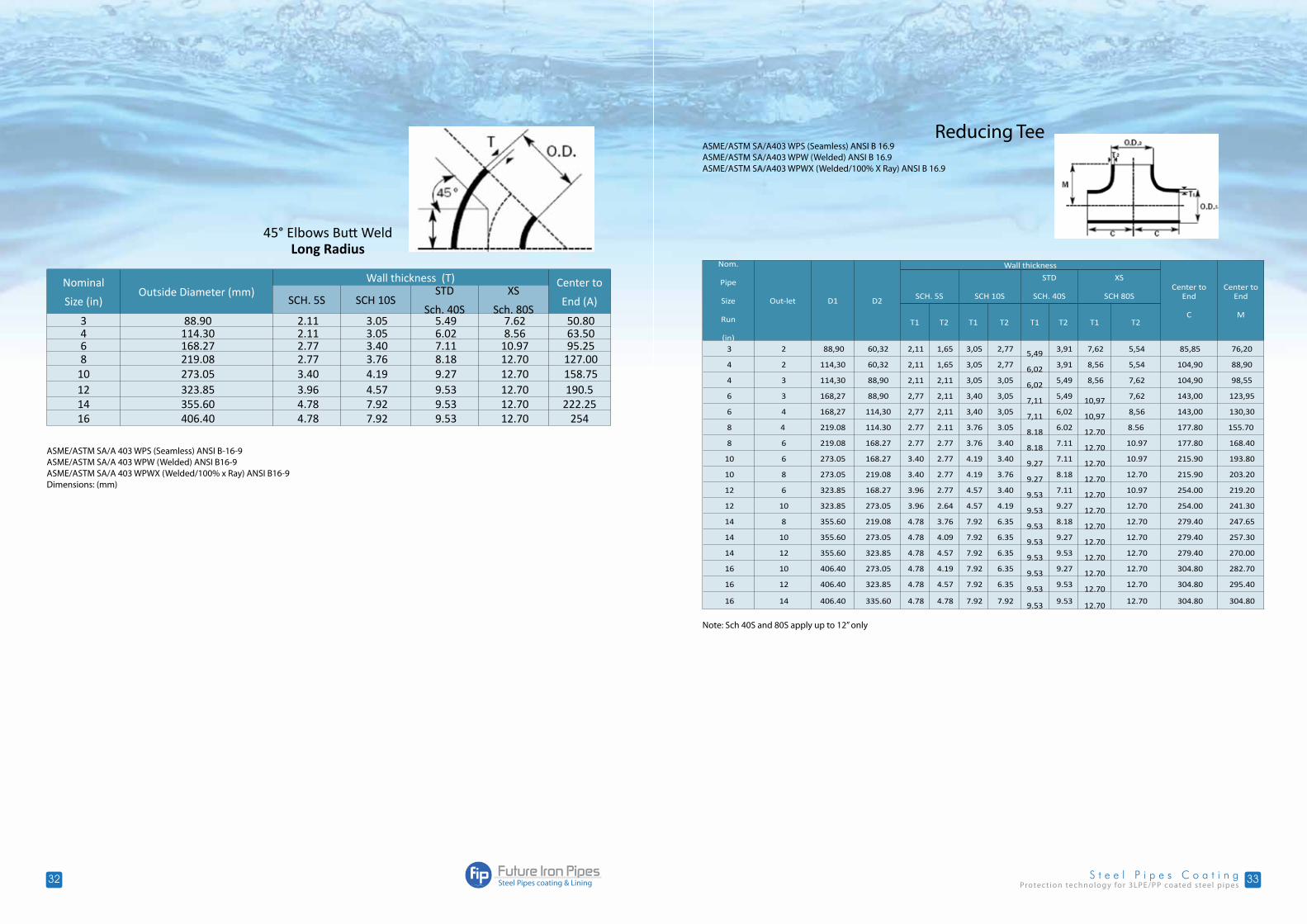
45° Elbows Butt WeldLong Radius
Nominal
Size (in)Outside Diameter (mm)
Wall thickness (T) Center to
End (A)SCH. 5S SCH 10SSTD
Sch. 40S
XS
Sch. 80S3 88.90 2.11 3.05 5.49 7.62 50.80 4 114.30 2.11 3.05 6.02 8.56 63.50 6 168.27 2.77 3.40 7.11 10.97 95.25 8 219.08 2.77 3.76 8.18 12.70 127.00
10 273.05 3.40 4.19 9.27 12.70 158.75 12 323.85 3.96 4.57 9.53 12.70 190.514 355.60 4.78 7.92 9.53 12.70 222.2516 406.40 4.78 7.92 9.53 12.70 254
ASME/ASTM SA/A 403 WPS (Seamless) ANSI B-16-9ASME/ASTM SA/A 403 WPW (Welded) ANSI B16-9ASME/ASTM SA/A 403 WPWX (Welded/100% x Ray) ANSI B16-9Dimensions: (mm)
Nom.
Pipe
Size
Run
(in)
Out-let D1 D2
Wall thickness
Center to End
C
Center to End
M
SCH. 5S SCH 10S
STD
SCH. 40S
XS
SCH 80S
T1 T2 T1 T2 T1 T2 T1 T2
3 2 88,90 60,32 2,11 1,65 3,05 2,77 5,49 3,91 7,62 5,54 85,85 76,20
4 2 114,30 60,32 2,11 1,65 3,05 2,77 6,02 3,91 8,56 5,54 104,90 88,90
4 3 114,30 88,90 2,11 2,11 3,05 3,05 6,02 5,49 8,56 7,62 104,90 98,55
6 3 168,27 88,90 2,77 2,11 3,40 3,05 7,11 5,49
10,97 7,62 143,00 123,95
6 4 168,27 114,30 2,77 2,11 3,40 3,05 7,11 6,02
10,97 8,56 143,00 130,30
8 4 219.08 114.30 2.77 2.11 3.76 3.05 8.18 6.02
12.70 8.56 177.80 155.70
8 6 219.08 168.27 2.77 2.77 3.76 3.40 8.18 7.11
12.70 10.97 177.80 168.40
10 6 273.05 168.27 3.40 2.77 4.19 3.40 9.27 7.11
12.70 10.97 215.90 193.80
10 8 273.05 219.08 3.40 2.77 4.19 3.76 9.27 8.18
12.70 12.70 215.90 203.20
12 6 323.85 168.27 3.96 2.77 4.57 3.40 9.53 7.11
12.70 10.97 254.00 219.20
12 10 323.85 273.05 3.96 2.64 4.57 4.19 9.53 9.27
12.70 12.70 254.00 241.30
14 8 355.60 219.08 4.78 3.76 7.92 6.35 9.53 8.18
12.70 12.70 279.40 247.65
14 10 355.60 273.05 4.78 4.09 7.92 6.35 9.53 9.27
12.70 12.70 279.40 257.30
14 12 355.60 323.85 4.78 4.57 7.92 6.35 9.53 9.53
12.70 12.70 279.40 270.00
16 10 406.40 273.05 4.78 4.19 7.92 6.35 9.53 9.27
12.70 12.70 304.80 282.70
16 12 406.40 323.85 4.78 4.57 7.92 6.35 9.53 9.53
12.70 12.70 304.80 295.40
16 14 406.40 335.60 4.78 4.78 7.92 7.92 9.53 9.53
12.70 12.70 304.80 304.80
Note: Sch 40S and 80S apply up to 12” only
Reducing TeeASME/ASTM SA/A403 WPS (Seamless) ANSI B 16.9ASME/ASTM SA/A403 WPW (Welded) ANSI B 16.9ASME/ASTM SA/A403 WPWX (Welded/100% X Ray) ANSI B 16.9
34
w w w . f i p . p s
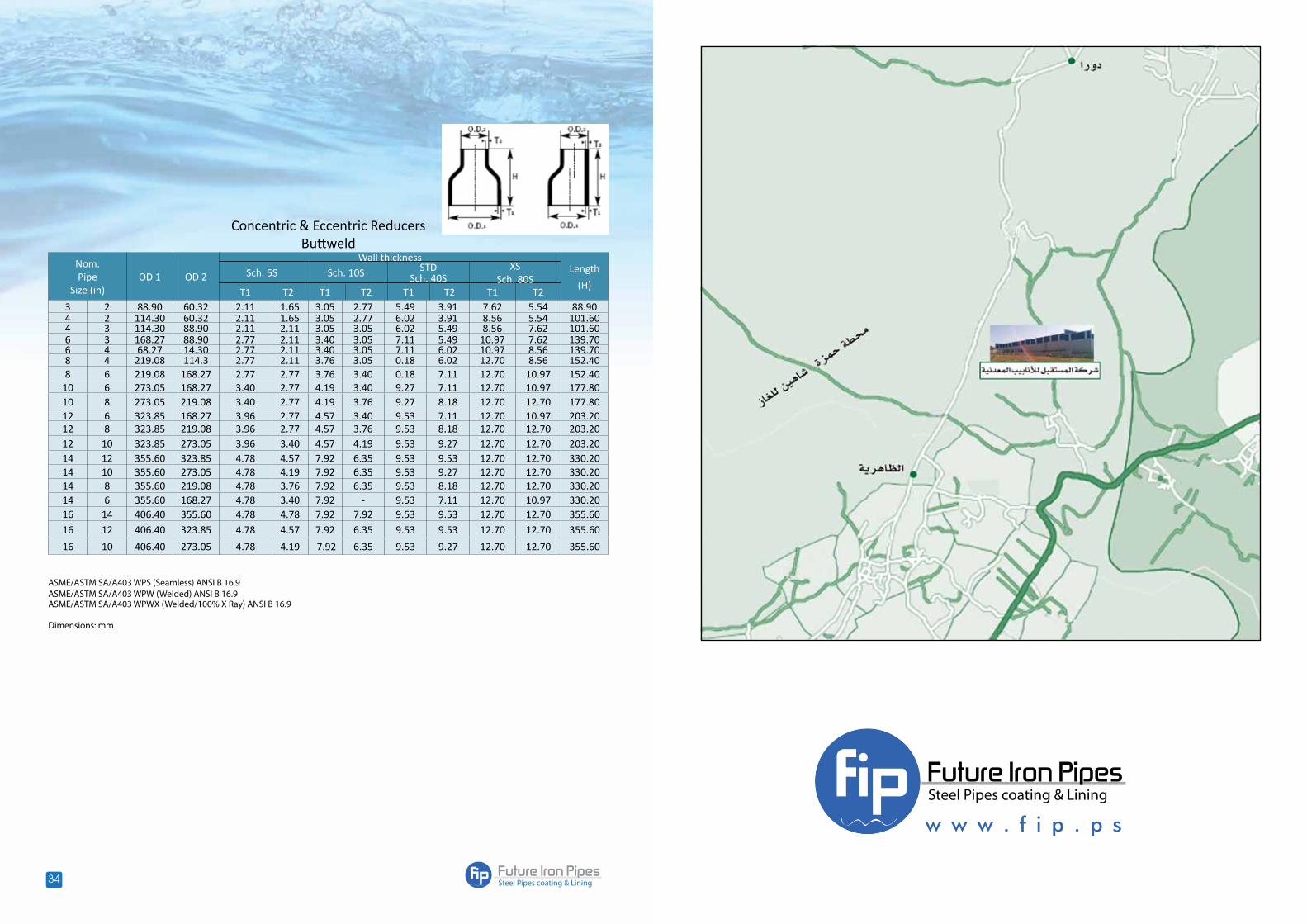
Concentric & Eccentric ReducersButtweld
Nom.Pipe
Size (in)OD 1 OD 2
Wall thicknessLength
(H)Sch. 5S Sch. 10S STD
Sch. 40SXS
Sch. 80ST1 T2 T1 T2 T1 T2 T1 T2
3 2 88.90 60.32 2.11 1.65 3.05 2.77 5.49 3.91 7.62 5.54 88.904 2 114.30 60.32 2.11 1.65 3.05 2.77 6.02 3.91 8.56 5.54 101.604 3 114.30 88.90 2.11 2.11 3.05 3.05 6.02 5.49 8.56 7.62 101.606 3 168.27 88.90 2.77 2.11 3.40 3.05 7.11 5.49 10.97 7.62 139.706 4 68.27 14.30 2.77 2.11 3.40 3.05 7.11 6.02 10.97 8.56 139.708 4 219.08 114.3 2.77 2.11 3.76 3.05 0.18 6.02 12.70 8.56 152.408 6 219.08 168.27 2.77 2.77 3.76 3.40 0.18 7.11 12.70 10.97 152.40
10 6 273.05 168.27 3.40 2.77 4.19 3.40 9.27 7.11 12.70 10.97 177.8010 8 273.05 219.08 3.40 2.77 4.19 3.76 9.27 8.18 12.70 12.70 177.8012 6 323.85 168.27 3.96 2.77 4.57 3.40 9.53 7.11 12.70 10.97 203.2012 8 323.85 219.08 3.96 2.77 4.57 3.76 9.53 8.18 12.70 12.70 203.2012 10 323.85 273.05 3.96 3.40 4.57 4.19 9.53 9.27 12.70 12.70 203.2014 12 355.60 323.85 4.78 4.57 7.92 6.35 9.53 9.53 12.70 12.70 330.2014 10 355.60 273.05 4.78 4.19 7.92 6.35 9.53 9.27 12.70 12.70 330.2014 8 355.60 219.08 4.78 3.76 7.92 6.35 9.53 8.18 12.70 12.70 330.2014 6 355.60 168.27 4.78 3.40 7.92 - 9.53 7.11 12.70 10.97 330.2016 14 406.40 355.60 4.78 4.78 7.92 7.92 9.53 9.53 12.70 12.70 355.6016 12 406.40 323.85 4.78 4.57 7.92 6.35 9.53 9.53 12.70 12.70 355.60
16 10 406.40 273.05 4.78 4.19 7.92 6.35 9.53 9.27 12.70 12.70 355.60
ASME/ASTM SA/A403 WPS (Seamless) ANSI B 16.9ASME/ASTM SA/A403 WPW (Welded) ANSI B 16.9ASME/ASTM SA/A403 WPWX (Welded/100% X Ray) ANSI B 16.9
Dimensions: mm


![FERRUM katalog A4 2018...Coating type standard 168.3-273 Érednica rury / Pipe diameter [mm] 323,9-457 508-559 610-762 Grubošt izolacji 3LPE i 3LPP / 3LPE and 3LPP coating thickness](https://img.dokumen.tips/doc/110x75/5f3e19f38466116ebe1bab07/ferrum-katalog-a4-coating-type-standard-1683-273-rednica-rury-pipe-diameter.jpg)


![FERRUM katalog A4 2018 · 2020-05-28 · Coating type standard 168.3-273 Érednica rury / Pipe diameter [mm] 323,9-457 508-559 610-762 Grubošt izolacji 3LPE i 3LPP / 3LPE and 3LPP](https://img.dokumen.tips/doc/110x75/5f3e19449dfce62743073b85/ferrum-katalog-a4-2018-2020-05-28-coating-type-standard-1683-273-rednica-rury.jpg)


