Embed Size (px)
Citation preview

© A. Benso - all rights reserved Version 1.0 2.3.1
2.1 – Partitioning-based System Design MethodologiesCSE 142
Partitioning-based System Design Methodologies
Alfredo BENSOPolitecnico di Torino (Italy)
UCSD, CA
211.4
Goal
• This lecture presents some Partitioning-based System Design Methodologies.

© A. Benso - all rights reserved Version 1.0 2.3.2
2.1 – Partitioning-based System Design MethodologiesCSE 142
311.4
Basic design strategy
Whenever the system to be implemented is complex enough not to be easily implemented by a single unit (i.e., a process), it’s convenient to partition it in functional units.
411.4
Side effects
Partitioning the system in several units improves design re-usability.

© A. Benso - all rights reserved Version 1.0 2.3.3
2.1 – Partitioning-based System Design MethodologiesCSE 142
511.4
Partitioning hints
It’s usually convenient to introduce, at least:• an Input Unit, charged of communicating with
the external world and of transforming input signals in an internal “suitable” form
• an Output Unit, charged of transforming internal signals in the form required by the external world
• a Main body, charged of performing the target operations.
611.4
Note
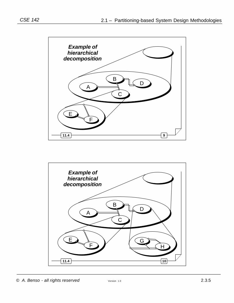
Partitioning is a typical example of the top-down design methodology, through a hierarchical decomposition, early introduced in lecture 2.1

© A. Benso - all rights reserved Version 1.0 2.3.4
2.1 – Partitioning-based System Design MethodologiesCSE 142
711.4
Example of hierarchical
decomposition
811.4
BD
AC
Example of hierarchical
decomposition
© A. Benso - all rights reserved Version 1.0 2.3.5
2.1 – Partitioning-based System Design MethodologiesCSE 142
911.4
BD
AC
EF
Example of hierarchical
decomposition
1011.4
BD
AC
EF
GH
Example of hierarchical
decomposition

© A. Benso - all rights reserved Version 1.0 2.3.6
2.1 – Partitioning-based System Design MethodologiesCSE 142
1111.4
C SPEC
Link with the hierarchy
IMPLEF
1211.4
Stopping condition
Partitionining stops when the “leaf”sub-systems are simpler enough to be “easily” implemented.

© A. Benso - all rights reserved Version 1.0 2.3.7
2.1 – Partitioning-based System Design MethodologiesCSE 142
1311.4
Basic assumptions
In the following, unless differently stated explicitly, we shall assume that:
• all the units run concurrently, clocked by a same master clock signal
• all the memory elements of all the units are clocked by the same clock edge (e.g., the rising one).
1411.4
Design steps
Identify the Input / Output signals of the target system, in terms of their names, type and width.
1

© A. Benso - all rights reserved Version 1.0 2.3.8
2.1 – Partitioning-based System Design MethodologiesCSE 142
1511.4
Example
data_in
counter
out_en
single bitstd_logicinreset
single bitstd_logicinclk
integer
std_logic
std_logic
single bitoutout_en
single bitindata_in
0 to 15outcounter
RangeTypeLabel
Elements definition:I/O

© A. Benso - all rights reserved Version 1.0 2.3.9
2.1 – Partitioning-based System Design MethodologiesCSE 142
single bitstd_logicinreset
single bitstd_logicinclk
integer
std_logic
std_logic
single bitoutout_en
single bitindata_in
0 to 15outcounter
RangeTypeLabel
Elements definition:I/OTo improve re-usability, never use
numbers; always resort to constants.
16integerconstantOUT_WIDTH
RangeTypeLabel
Elements definition:constants

© A. Benso - all rights reserved Version 1.0 2.3.10
2.1 – Partitioning-based System Design MethodologiesCSE 142
single bitstd_logicinreset
single bitstd_logicinclk
integer
std_logic
std_logic
single bitoutout_en
single bitindata_in
0 to OUT_WIDTH-1outcounter
RangeTypeLabel
Elements definition:I/O
2011.4
Design steps
Identify the functional units the system has to be partitioned in (Top-level partitioning)
2

© A. Benso - all rights reserved Version 1.0 2.3.11
2.1 – Partitioning-based System Design MethodologiesCSE 142
2111.4
Main UnitInput Unit
Example of Top level partitioning
data_in
counter
out_en
2211.4
Design steps
Define the communication channels among the functional units, in terms of their type and width.
3

© A. Benso - all rights reserved Version 1.0 2.3.12
2.1 – Partitioning-based System Design MethodologiesCSE 142
2311.4
data_in
num counter
Main Unitsig-ctr
Input Unitout_en
Example
2411.4
Design steps
Implement each functional unit separately.
4
© A. Benso - all rights reserved Version 1.0 2.3.13
2.1 – Partitioning-based System Design MethodologiesCSE 142
2511.4
Unit implementation
Describe the behavior of each unit as a process.
Two cases can usually occur:
• The unit is rather “simple”, i.e., its behavior can be described as a straight piece of behavioral VHDL, without resorting to the introduction of “states”
• The unit is more “complex”, i.e., its behavior can be described only by resorting to the introduction of “states” the process evolves through.
2611.4
An example
A ROM memory (1K x 16) stores 1024 data of 16 bits each, represented according to the “2’s complement” notation.
On a serial transmission line, 16-bits numbers are transmitted synchronously w.r.t. a clock signal clk, one bit per clock cycle, according to the following protocol:
• Numbers are transmitted LSB first
• Each new number has a 4 bit header : “1111”
• 6,000+ clock cycles occur between two consecutive transmitted numbers.
© A. Benso - all rights reserved Version 1.0 2.3.14
2.1 – Partitioning-based System Design MethodologiesCSE 142
2711.4
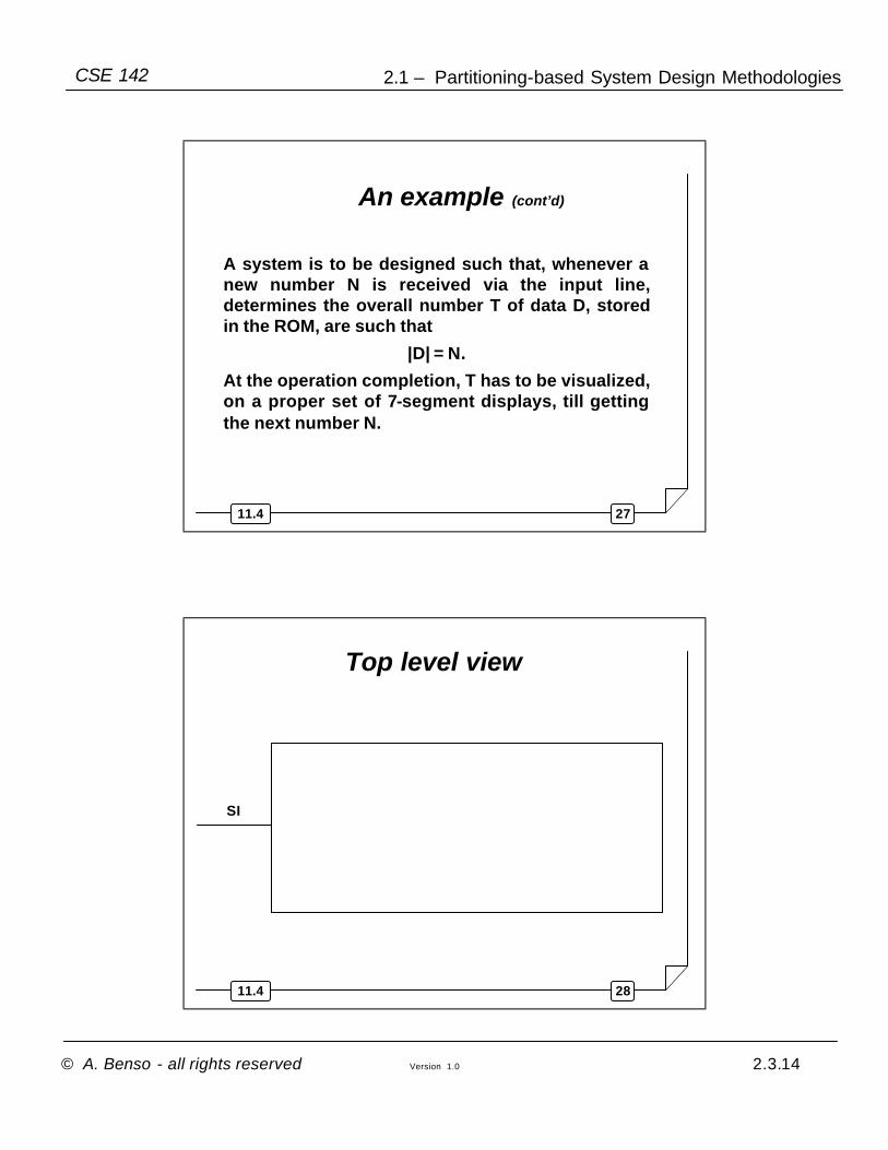
A system is to be designed such that, whenever a new number N is received via the input line, determines the overall number T of data D, stored in the ROM, are such that
|D| = N.
At the operation completion, T has to be visualized, on a proper set of 7-segment displays, till getting the next number N.
An example (cont’d)
2811.4
Top level view
SI
© A. Benso - all rights reserved Version 1.0 2.3.15
2.1 – Partitioning-based System Design MethodologiesCSE 142
2911.4
Main UnitInput Unit
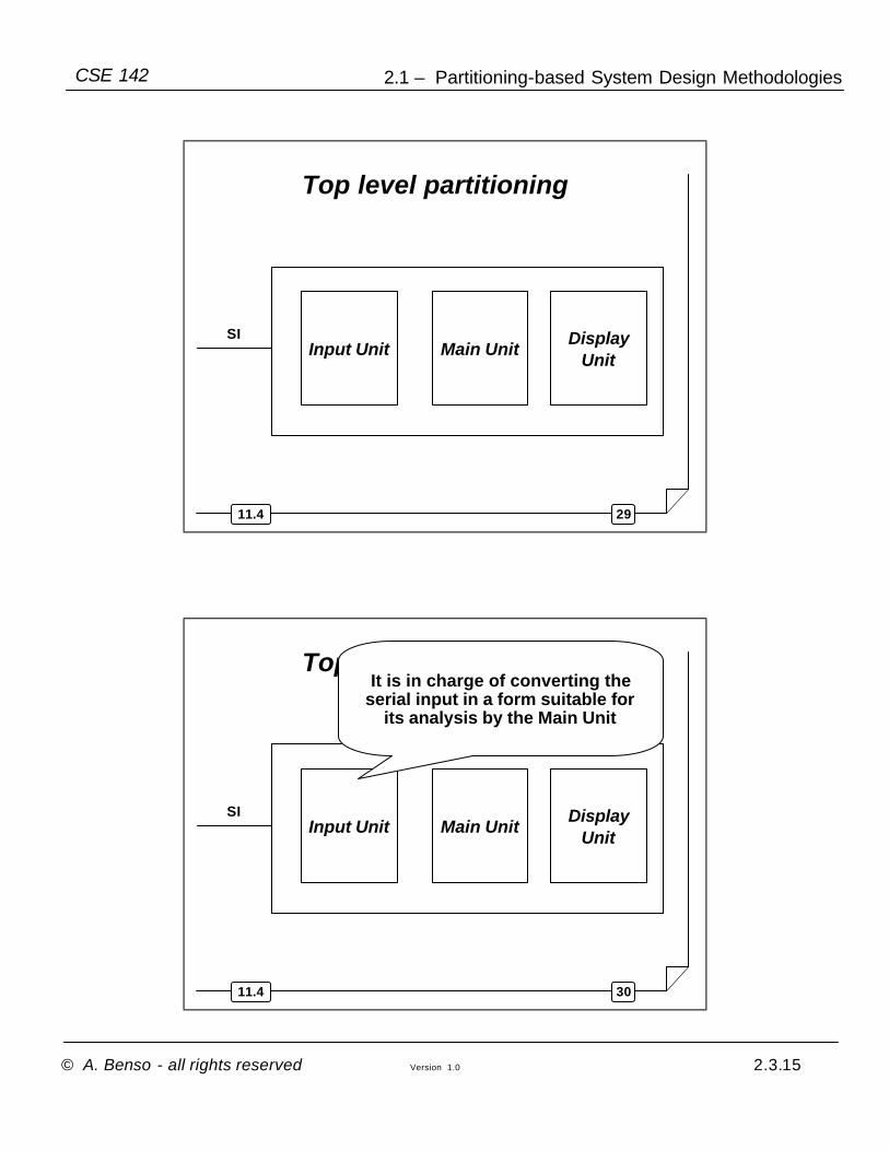
Top level partitioning
SI DisplayUnit
3011.4
Main UnitInput Unit
Top level partitioning
SI DisplayUnit
It is in charge of converting the serial input in a form suitable for
its analysis by the Main Unit
© A. Benso - all rights reserved Version 1.0 2.3.16
2.1 – Partitioning-based System Design MethodologiesCSE 142
3111.4
Main UnitInput Unit
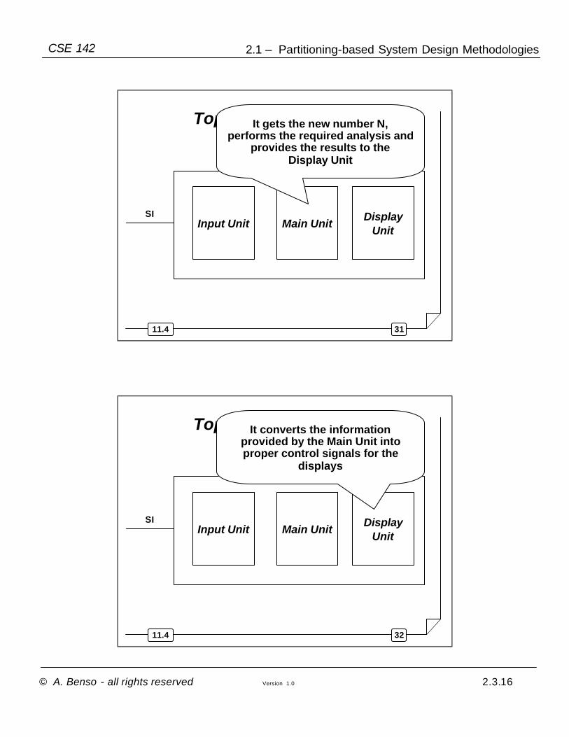
Top level partitioning
SI DisplayUnit
It gets the new number N, performs the required analysis and
provides the results to the Display Unit
3211.4
Main UnitInput Unit
Top level partitioning
SI DisplayUnit
It converts the information provided by the Main Unit into proper control signals for the
displays

© A. Benso - all rights reserved Version 1.0 2.3.17
2.1 – Partitioning-based System Design MethodologiesCSE 142
3311.4
Top level partitioning (cont’d)
SI
match_count
display_en
N
strobeMain Unit
DisplayUnit
Input Unit
3411.4
Design of the Main Unit
match_count
display_en
N
strobeMain Unit

© A. Benso - all rights reserved Version 1.0 2.3.18
2.1 – Partitioning-based System Design MethodologiesCSE 142
16integerconstantROM_WIDTH
integer 1024constantROM_SIZE
RangeTypeLabel
Elements definition:constants
0 to (2**ROM_WIDTH)-1
integerinN
single bitstd_logicinreset
single bitstd_logicinclk
integer
std_logic
std_logic
single bitoutdisplay_en
single bitinstrobe
0 to ROM_SIZEoutmatch_count
RangeTypeLabel
Elements definition:I/O

© A. Benso - all rights reserved Version 1.0 2.3.19
2.1 – Partitioning-based System Design MethodologiesCSE 142
integer
integer
0 to ROM_SIZE -1signaladdress
-2**(ROM_WIDTH -1) to
2**(ROM_WIDTH -1)-1signalacc
RangeTypeLabel
Elements definition:internal signals
3811.4
Intermediate STG of the Main Unit
match_count <= 0acc <= 0
address <= 0display_en <= ‘0’
init

© A. Benso - all rights reserved Version 1.0 2.3.20
2.1 – Partitioning-based System Design MethodologiesCSE 142
3911.4
initIf strobe = 1 else
Inizialize all the sequential elements:[match_count <= 0;
acc <= 0;address <= 0]
Turn the display off:[display_en <= ‘0’]
acc <= ROM(address)
get_new_word
check
4011.4
checkabs(acc) ≤ N else
match_count <= match_count + 1;
init
All the cells have been considered
[address = ROM_SIZE -1]else
Turn the display on:[display_en <= ‘1’]
get_new_word
address <= address + 1;

© A. Benso - all rights reserved Version 1.0 2.3.21
2.1 – Partitioning-based System Design MethodologiesCSE 142