Embed Size (px)
Citation preview

2 0 1 4
JUNIO

2 0 1 4
2La marca GOODYEAR (y el pie alado) es usada por Veyance Productos de Ingeniería, S. de R.L. de C.V. bajo la licencia de The Goodyear Tire & Rubber Company. La marca Goodyear Engineered Products es fabricada y distribuída exclusivamente por Veyance Technologies, Inc. y sus afiliados. ®2012 Derechos Reservados.
SUSPENSIONES NEUMATICAS, CARACTERISTICAS Y BENEFICOS
Gran Nivel de Aislamiento• Reduce la necesidad de mantenimiento a instrumental eléctrico/electrónico de la unidad• Reduce daños a la cabina y en general a la unidad• Reduce el desgaste de los ejes, transmisión y las llantas• Reduce el tiempo de servicio• Extiende la vida útil de la unidad• Reduce los daños por fatiga al vehículo
Para el dueño de la unidad, la suspensión neumática
• Mejora el aislamiento en condiciones de carga completa y sin carga• Amplia la gama de carga disponibles para la transportación, incluyendo equipo electrónico, donde la suspensión neumática reduce daños a la carga.• Gran confort al operador• Incrementa el valor de reventa de la unidad protege bisagras, remaches, luces y todos los accesorios del remolque
Razones para aumentar el uso de la suspensión neumática
• Los fabricantes de suspensión le han incorporado un mayor grado de durabilidad, por lo tanto ofrecen períodos de garantía más largos.• Incrementa la implementación del eje retráctil
No. Competidor No. GoodyearEP
AMERICAN CARRIER
Air Spring Bellows
8003-005 2B14-355
8003-006 2B8-550
8003-007 1B14-351
AMERICAN CARRIER
Air Spring Rolling Lobe
8003-003 1R11-171
8003-023 1R11-161
AUTO BUS
Air Spring Rolling Lobe
10530087 1R10-089
BLUEBIRD
Air Spring Rolling Lobe
1286814 1R11-151
12TA-1-2 1R12-095
300-961250 1R12-095
No. Competidor No. GoodyearEP
990671 1R10-087
BOSTROMAIR SPRING SLEEVE
1201542-01 1S4-196
1108707-001 1S4-197
CHANCE BUS
Air Spring Rolling Lobe
23891728 1R11-152
CONTITECH
Air Spring Bellows
FD110-15766 2B6-535
FD120-20509 2B8-550
FD200-19310 2B9-239
FD200-19315 2B9-206
FD200-19320 2B9-200
FD200-19362 2B9-210
FD200-19448 2B9-252
FD200-19448 2B9-265
No. Competidor No. GoodyearEP
FD200-19448 2B9-280
FD200-19450 2B9-230
FD200-19452 2B9-246
FD200-19499 2B9-201
FD200-19504 2B9-288
FD200-19505 2B9-229
FD200-19510 2B9-245
FD200-22524 2B10-226
FD200-22706 2B9-229
FD200-25426 2B9-250
FD200-25427 2B9-253
FD200-25428 2B9-255
FD200-25429 2B9-251
FD200-25453 2B9-218
FD200-25454 2B9-266
FD200-25463 2B9-254
FD330-22313 2B12-309
No. Competidor No. GoodyearEP
FD330-22318 2B12-307
FD330-22327 2B12-300
FD330-22331 2B12-406
FD330-22334 2B12-320
FD330-22343 2B12-427
FD330-22346 2B12-410
FD330-22363 2B12-425
FD330-22364 2B12-313
FD330-22365 2B12-426
FD330-22367 2B12-319
FD330-22368 2B12-432
FD330-22465 2B12-432
FD330-22471 2B12-412
FD330-22472 2B12-411
FD330-22500 2B12-304
FD330-22540 2B12-463
FD330-22780 2B12-429

2 0 1 4
3La marca GOODYEAR (y el pie alado) es usada por Veyance Productos de Ingeniería, S. de R.L. de C.V. bajo la licencia de The Goodyear Tire & Rubber Company. La marca Goodyear Engineered Products es fabricada y distribuída exclusivamente por Veyance Technologies, Inc. y sus afiliados. ®2012 Derechos Reservados.
No. Competidor No. GoodyearEP
FD330-30323 2B12-305
FD330-30340 2B12-324
FD330-30369 2B12-416
FD330-30369 2B12-446
FD330-30370 2B12-402
FD330-30371 2B12-434
FD330-30372 2B12-428
FD330-30464 2B12-434
FD330-30502 2B12-317
FD330-30513 2B12-324
FD331-26480 2B12-440
FD331-26514 2B12-345
FD331-26541 2B12-346
FD530-22311 2B14-360
FD530-22316 2B14-359
FD530-22321 2B14-356
FD530-22342 2B14-355
FD530-22345 2B14-367
FD530-22374 2B14-354
FD530-30449 2B14-366
FD530-30451 2B14-365
FD530-30532 2B14-462
FD530-35530 2B14-383
FD530-35543 2B14-476
FD530-35544 2B14-470
FD530-35720 2B14-462
FS330-11468 1B12-301
FS530-14339 1B14-358
FS530-14442 1B14-350
FS530-14446 1B14-351
FS530-14447 1B14-351
FT330-29413 3B12-319
FT330-29431 3B12-300
FT330-29432 3B12-301
FT330-29434 3B12-303
FT330-29466 3B12-310
FT330-29469 3B12-300
FT330-29498 3B12-301
FT330-29503 3B12-304
FT330-29508 3B12-312
FT330-29520 3B12-335
FT330-29525 3B12-312
FT330-29546 3B12-328
FT330-29547 3B12-315
FT330-29547 3B12-329
FT330-29723 3B12-335
FT530-32325 3B14-359
FT530-32329 3B14-356
No. Competidor No. GoodyearEP
FT530-32333 3B14-360
FT530-32336 3B14-354
FT530-35441 3B14-452
FT530-35455 3B14-364
FT530-35456 3B14-451
FT530-35457 3B14-367
CONTITECH
Air Spring Rolling Lobe
1010-15P453 1R13-159
1010-15S518 1R13-097
1010-15S522 1R13-124
1010-15S711 1R13-124
1010-15S871 1R13-109
1010-165S783 1R13-039
1010-16S526 1R13-177
1010-16S533 1R13-176
1010-16S724 1R13-155
1010-21P434 1R13-118
1010-21P486 1R13-153
1010-21P570 1R13-152
10105-15P460 1R13-159
1010B-13S51 1R13-130
11105-15A414 1R14-037
11105-15A415 1R14-038
11105-15A422 1R13-120
11105-17A316 1R14-028
11105-17A364 1R14-026
11105-17A365 1R14-018
11105-17A366 1R14-028
11105-17A367 1R14-115
11105-17A377 1R14-160
11105-17A405 1R14-159
11105-17A507 1R14-130
11105-19A431 1R14-137
11105-21A313 1R13-038
11105-21A313 1R14-045
11105-21A318 1R14-030
11105-21A369 1R14-019
11105-21A370 1R14-019
11105-22A530 1R14-174
11105-22A752 1R14-170
11105-22S712 1R14-127
11105-22S750 1R14-113
11105-22S764 1R14-113
11105A-16P5 1R14-171
11105C-16A3 1R14-039
11105C-16A3 1R14-042
No. Competidor No. GoodyearEP
11105C-16A3 1R14-147
11105C-16A7 1R14-039
11105F-17P74 1R14-172
11105F-17P74 1R14-190
64382 1R12-663
64761 1R12-613
910-10P311 1R12-095
910-10P328 1R12-351
910-10P331 1R12-359
910-10P339 1R12-350
910-10P397 1R12-561
910-10P398 1R12-560
910-10P399 1R12-559
910-10P400 1R12-558
910-10P471 1R12-435
910-10P480 1R12-556
910-10P482 1R12-435
910-10P503 1R12-557
910-10P542 1R12-555
910-12A319 1R12-132
910-12A327 1R12-309
910-12A329 1R12-355
910-12A341 1R12-132
910-12A343 1R12-132
910-12A427 1R12-367
910-12A488 1R12-487
910-12A504 1R12-132
910-12P319 1R12-132
910-12P329 1R12-355
910-12P395 1R12-505
910-12P484 1R12-508
910-12P488 1R12-487
910-12P495 1R12-571
910-12P544 1R12-563
910-135S433 1R13-119
910-135S881 1R13-119
910-14A330 1R12-370
910-14A469 1R12-434
910-14A496 1R12-437
910-14A545 1R12-445
910-14A575 1R12-636
910-14A707 1R12-512
910-14AT75 1R12-543
910-14P312 1R12-069
910-14P312 1R12-669
910-14P345 1R12-352
910-14P345 1R12-421
910-14P450 1R12-205
No. Competidor No. GoodyearEP
910-14P461 1R12-325
910-14P462 1R12-438
910-14P465 1R12-620
910-14P469 1R12-434
910-14P709 1R12-285
910-16374M 1R12-014
910-16P310 1R12-092
910-16P310 1R12-509
910-16P325 1R12-155
910-16P325 1R12-358
910-16P332 1R12-621
910-16P333 1R12-066
910-16P350 1R12-092
910-16P352 1R12-356
910-16P353 1R12-130
910-16P372 1R12-220
910-16P376 1R12-143
910-16P391 1R12-441
910-16P393 1R12-567
910-16P407 1R12-090
910-16P408 1R12-182
910-16P409 1R12-188
910-16P410 1R12-365
910-16P416 1R12-400
910-16P449 1R12-615
910-16P497 1R12-436
910-16P710 1R12-366
910-16P769 1R12-541
910-16P770 1R12-576
910-16S374 1R12-047
910-175A802 1R12-494
910-175P406 1R12-424
910-175P428 1R12-498
910-175P429 1R12-481
910-175P436 1R12-366
910-175P440 1R12-403
910-175P443 1R12-502
910-175P445 1R12-586
910-175P451 1R12-404
910-175P454 1R12-499
910-175P456 1R12-538
910-175P502 1R12-504
910-175P519 1R12-403
910-175P520 1R12-402
910-175P521 1R12-401
910-175P548 1R12-532
910-175P571 1R12-554
910-175P572 1R12-552
2 0 1 4
4La marca GOODYEAR (y el pie alado) es usada por Veyance Productos de Ingeniería, S. de R.L. de C.V. bajo la licencia de The Goodyear Tire & Rubber Company. La marca Goodyear Engineered Products es fabricada y distribuída exclusivamente por Veyance Technologies, Inc. y sus afiliados. ®2012 Derechos Reservados.
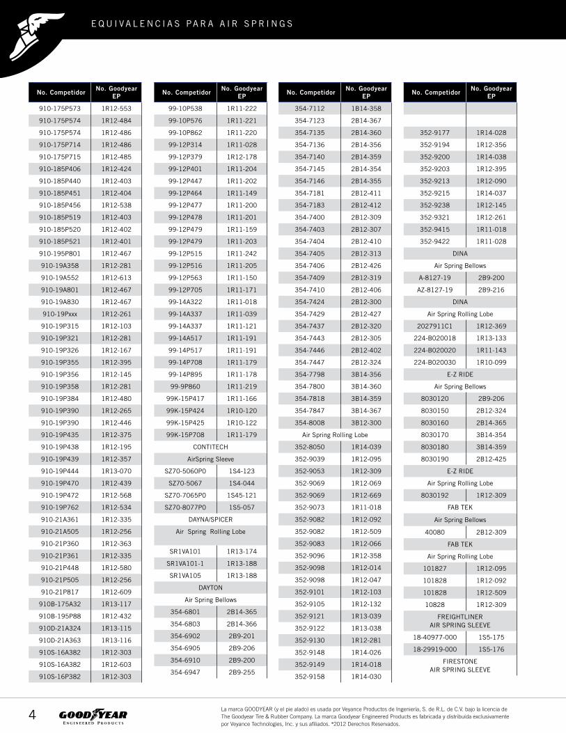
No. Competidor No. GoodyearEP
352-9177 1R14-028
352-9194 1R12-356
352-9200 1R14-038
352-9203 1R12-395
352-9213 1R12-090
352-9215 1R14-037
352-9238 1R12-145
352-9321 1R12-261
352-9415 1R11-018
352-9422 1R11-028
DINA
Air Spring Bellows
A-8127-19 2B9-200
AZ-8127-19 2B9-216
DINA
Air Spring Rolling Lobe
2027911C1 1R12-369
224-B020018 1R13-133
224-B020020 1R11-143
224-B020030 1R10-099
E-Z RIDE
Air Spring Bellows
8030120 2B9-206
8030150 2B12-324
8030160 2B14-365
8030170 3B14-354
8030180 3B14-359
8030190 2B12-425
E-Z RIDE
Air Spring Rolling Lobe
8030192 1R12-309
FAB TEK
Air Spring Bellows
40080 2B12-309
FAB TEK
Air Spring Rolling Lobe
101827 1R12-095
101828 1R12-092
101828 1R12-509
10828 1R12-309
FREIGHTLINERAIR SPRING SLEEVE
18-40977-000 1S5-175
18-29919-000 1S5-176
FIRESTONEAIR SPRING SLEEVE
No. Competidor No. GoodyearEP
910-175P573 1R12-553
910-175P574 1R12-484
910-175P574 1R12-486
910-175P714 1R12-486
910-175P715 1R12-485
910-185P406 1R12-424
910-185P440 1R12-403
910-185P451 1R12-404
910-185P456 1R12-538
910-185P519 1R12-403
910-185P520 1R12-402
910-185P521 1R12-401
910-195P801 1R12-467
910-19A358 1R12-281
910-19A552 1R12-613
910-19A801 1R12-467
910-19A830 1R12-467
910-19Pxxx 1R12-261
910-19P315 1R12-103
910-19P321 1R12-281
910-19P326 1R12-167
910-19P355 1R12-395
910-19P356 1R12-145
910-19P358 1R12-281
910-19P384 1R12-480
910-19P390 1R12-265
910-19P390 1R12-446
910-19P435 1R12-375
910-19P438 1R12-195
910-19P439 1R12-357
910-19P444 1R13-070
910-19P470 1R12-439
910-19P472 1R12-568
910-19P762 1R12-534
910-21A361 1R12-335
910-21A505 1R12-256
910-21P360 1R12-363
910-21P361 1R12-335
910-21P448 1R12-580
910-21P505 1R12-256
910-21P817 1R12-609
910B-175A32 1R13-117
910B-195P88 1R12-432
910D-21A324 1R13-115
910D-21A363 1R13-116
910S-16A382 1R12-303
910S-16A382 1R12-603
910S-16P382 1R12-303
No. Competidor No. GoodyearEP
99-10P538 1R11-222
99-10P576 1R11-221
99-10P862 1R11-220
99-12P314 1R11-028
99-12P379 1R12-178
99-12P401 1R11-204
99-12P447 1R11-202
99-12P464 1R11-149
99-12P477 1R11-200
99-12P478 1R11-201
99-12P479 1R11-159
99-12P479 1R11-203
99-12P515 1R11-242
99-12P516 1R11-205
99-12P563 1R11-150
99-12P705 1R11-171
99-14A322 1R11-018
99-14A337 1R11-039
99-14A337 1R11-121
99-14A517 1R11-191
99-14P517 1R11-191
99-14P708 1R11-179
99-14P895 1R11-178
99-9P860 1R11-219
99K-15P417 1R11-166
99K-15P424 1R10-120
99K-15P425 1R10-122
99K-15P708 1R11-179
CONTITECH
AirSpring Sleeve
SZ70-5060P0 1S4-123
SZ70-5067 1S4-044
SZ70-7065P0 1S45-121
SZ70-8077P0 1S5-057
DAYNA/SPICER
Air Spring Rolling Lobe
SR1VA101 1R13-174
SR1VA101-1 1R13-188
SR1VA105 1R13-188
DAYTON
Air Spring Bellows
354-6801 2B14-365
354-6803 2B14-366
354-6902 2B9-201
354-6905 2B9-206
354-6910 2B9-200
354-6947 2B9-255
No. Competidor No. GoodyearEP
354-7112 1B14-358
354-7123 2B14-367
354-7135 2B14-360
354-7136 2B14-356
354-7140 2B14-359
354-7145 2B14-354
354-7146 2B14-355
354-7181 2B12-411
354-7183 2B12-412
354-7400 2B12-309
354-7403 2B12-307
354-7404 2B12-410
354-7405 2B12-313
354-7406 2B12-426
354-7409 2B12-319
354-7410 2B12-406
354-7424 2B12-300
354-7429 2B12-427
354-7437 2B12-320
354-7443 2B12-305
354-7446 2B12-402
354-7447 2B12-324
354-7798 3B14-356
354-7800 3B14-360
354-7818 3B14-359
354-7847 3B14-367
354-8008 3B12-300
Air Spring Rolling Lobe
352-8050 1R14-039
352-9039 1R12-095
352-9053 1R12-309
352-9069 1R12-069
352-9069 1R12-669
352-9073 1R11-018
352-9082 1R12-092
352-9082 1R12-509
352-9083 1R12-066
352-9096 1R12-358
352-9098 1R12-014
352-9098 1R12-047
352-9101 1R12-103
352-9105 1R12-132
352-9121 1R13-039
352-9122 1R13-038
352-9130 1R12-281
352-9148 1R14-026
352-9149 1R14-018
352-9158 1R14-030

2 0 1 4
5La marca GOODYEAR (y el pie alado) es usada por Veyance Productos de Ingeniería, S. de R.L. de C.V. bajo la licencia de The Goodyear Tire & Rubber Company. La marca Goodyear Engineered Products es fabricada y distribuída exclusivamente por Veyance Technologies, Inc. y sus afiliados. ®2012 Derechos Reservados.
No. Competidor No. GoodyearEP
5770 1R10-101
5779 1R12-303
8058 1R14-039
8050 1R14-039
8052 1R14-042
8053 1R14-147
8091 1R14-171
8197 1R12-562
8204 1R12-508
8527 1R12-603
8708 1R13-177
8709 1R13-159
8710 1R13-124
8713 1R13-176
8729 1R13-130
8748 1R13-152
8749 1R13-153
8751 1R13-159
8752 1R13-138
8754 1R13-053
8755 1R13-124
8778 1R14-130
8782 1R13-109
8792 1R14-045
8802 1R12-434
8805 1R12-438
8806 1R12-445
8829 1R12-615
8852 1R12-568
8899 1R10-108
8900 1R11-204
8901 1R11-149
8919 1R11-191
8924 1R12-436
8934 1R12-563
8944 1R12-366
8961 1R12-555
8964 1R12-556
8976 1R12-557
8986 1R12-558
8997 1R9-065
9010 1R12-421
9015 1R12-366
9017 1R10-085
9017 1R10-089
9018 1R12-304
9026 1R12-567
9029 1R12-559
No. Competidor No. GoodyearEP
7205/ 7215/ 7207 1S5-175
7206/ 7202 1S5-176
3000 1S3-013
3001 1S3-013
4001 1S3-011
7001 1S4-007
7002 1S4-007
7003 1S4-035
7007 1S4-067
7010 1S4-008
7014 1S5-120
7017 1S5-006
7017 1S5-120
7031 1S4-007
7035 1S45-121
7040 1S4-056
7042 1S5-120
7044 1S5-120
7050 1S4-035
7055 1S4-035
7056 1S45-113
7080 1S45-107
7081 1S5-038
7086 1S4-058
7087 1S5-040
7108 1S5-057
7110 1S5-152
W023587036 1S5-186
FIRESTONE
Air Spring Bellows
6799 2B14-476
6801 2B14-365
6803 2B14-366
6805 2B14-462
6850 2B12-463
6897 2B9-229
6902 2B9-239
6905 2B9-206
6908 2B9-210
6910 2B9-200
6920 1B12-305
6926 2B9-288
6927 2B9-218
6928 2B9-225
6932 2B9-246
6935 2B9-201
6940 2B9-230
6941 2B9-280
No. Competidor No. GoodyearEP
6943 2B9-250
6944 2B9-252
6945 2B9-253
6946 2B9-254
6947 2B9-255
6948 2B9-251
7009 1B12-301
7043 1B12-305
7103 1B14-350
7105 1B14-351
7112 1B14-358
7119 2B9-240
7123 2B14-367
7124 2B12-340
7133 2B14-367
7135 2B14-360
7136 2B14-356
7140 2B14-359
7145 2B14-354
7146 2B14-355
7180 2B12-425
7181 2B12-411
7183 2B12-412
7184 2B12-429
7185 2B12-318
7325 2B8-550
7344 2B12-304
7400 2B12-309
7401 2B12-320
7403 2B12-307
7404 2B12-410
7405 2B12-313
7406 2B12-426
7409 2B12-319
7410 2B12-406
7423 2B12-432
7424 2B12-300
7429 2B12-427
7437 2B12-320
7443 2B12-305
7444 2B12-416
7444 2B12-446
7446 2B12-402
7447 2B12-324
7472 2B12-434
7473 2B12-428
7499 2B12-317
7545 2B12-345
No. Competidor No. GoodyearEP
7550 2B12-346
7555 2B12-440
7557 2B14-383
7782 2B14-470
7788 2B9-245
7790 2B12-324
7795 2B10-226
7798 3B14-356
7800 3B14-360
7808 3B14-354
7816 3B14-359
7818 3B14-359
7843 3B14-457
7846 3B14-451
7847 3B14-459
7850 3B14-452
7862 3B14-464
7990 3B12-329
7994 3B12-328
7995 3B12-329
7996 3B12-335
8006 3B12-304
8008 3B12-300
8010 3B12-301
8018 3B12-303
8025 3B12-300
8027 3B12-310
8030 3B12-301
8032 3B12-319
8033 3B12-312
8038 3B12-415
8039 3B12-416
8042 3B12-322
8043 3B12-323
8047 3B12-326
8048 3B12-325
W013587996 3B12-335
Air Spring Rolling Lobe
2119 1R9-065
5406 1R9-038
5409 1R9-003
5410 1R9-070
5503 1R14-174
5505 1R14-113
5710 1R8-034
5730 1R8-034
5739 1R11-088
5766 1R11-161

2 0 1 4
6La marca GOODYEAR (y el pie alado) es usada por Veyance Productos de Ingeniería, S. de R.L. de C.V. bajo la licencia de The Goodyear Tire & Rubber Company. La marca Goodyear Engineered Products es fabricada y distribuída exclusivamente por Veyance Technologies, Inc. y sus afiliados. ®2012 Derechos Reservados.
No. Competidor No. GoodyearEP
9936 1R12-499
9961 1R14-115
W013588713 1R13-176
W013588753 1R13-207
W013588755 1R13-124
W013589039 1R12-095
W013589265 1R12-375
W013589270 1R13-119
W013589320 1R12-663
W013589580 1R13-118
W01-358-9616 1R11-242
W013589622 1R11-221
W013589780 1R12-303
W013589807 1R12-1047
W013589921 1R12-502
W013589974 1R12-1048
W015449542 1R11-268
FLEXIBLE
Air Spring Bellows
6-336-13 2B12-304
6-336-5 2B12-304
FLXIBLE
Air Spring Rolling Lobe
6-304-156 1R8-034
6-304-157 1R10-089
6-336-11 1R9-003
6-336-15 1R10-091
6-336-166 1R9-047
6-336-174 1R10-089
6-336-175 1R8-034
6-336-182 1R10-091
6-336-183 1R14-112
6-336-200 1R11-121
6-336-202 1R12-095
6-336-209 1R10-019
6-336-212 1R10-087
6-841-92 1R10-089
87-0808-0000 1R14-101
97-240-153 1R10-089
97-2410-0000 1R12-169
97-2410-1 1R12-169
97-2410-2 1R12-169
97-2410-3 1R12-169
97-2410-4 1R12-169
97-2410-5 1R12-169
97-5382-001 1R14-101
97-6693-1 1R12-169
97-6694-1 1R14-101
No. Competidor No. GoodyearEP
9031 1R12-350
9033 1R12-351
9039 1R12-095
9043 1R10-105
9053 1R12-309
9067 1R10-089
9069 1R12-069
9069 1R12-669
9070 1R12-370
9077 1R12-359
9078 1R12-355
9082 1R12-092
9082 1R12-509
9083 1R12-066
9092 1R12-220
9093 1R12-621
9096 1R12-155
9096 1R12-358
9098 1R12-047
9100 1R12-076
9101 1R12-103
9105 1R12-132
9113 1R12-132
9115 1R10-019
9121 1R13-039
9122 1R14-045
9127 1R12-512
9130 1R12-281
9134 1R14-137
9144 1R14-160
9148 1R14-026
9149 1R14-018
9152 1R14-019
9158 1R14-030
9164 1R14-159
9177 1R14-028
9179 1R14-028
9192 1R12-185
9194 1R12-356
9200 1R14-038
9203 1R12-395
9213 1R12-090
9215 1R14-037
9218 1R13-120
9219 1R12-182
9223 1R12-188
9227 1R12-130
FIRESTONE
No. Competidor No. GoodyearEP
Air Spring Rolling Lobe
9236HR 1R10-089
9238 1R12-145
9241 1R12-261
9243 1R12-480
9245 1R12-446
9250 1R13-115
9252 1R13-116
9262 1R13-118
9264 1R14-127
9265 1R12-375
9270 1R13-119
9275 1R13-117
9287 1R12-424
9291 1R10-122
9293 1R10-120
9295 1R11-166
9296 1R12-400
9297 1R12-402
9299 1R12-366
9302 1R12-132
9303 1R12-132
9306 1R12-530
9307 1R12-435
9308 1R12-560
9320 1R12-363
9321 1R12-335
9325 1R12-505
9332 1R12-561
9334 1R12-435
9335 1R12-620
9336 1R12-648
9346 1R12-439
9348 1R12-357
9349 1R12-195
9362 1R12-441
9365 1R12-571
9366 1R12-487
9367 1R12-256
9370 1R12-580
9371 1R12-401
9373 1R12-403
9375 1R12-404
9376 1R11-200
9377 1R11-201
9378 1R11-202
9379 1R12-178
9380 1R10-091
No. Competidor No. GoodyearEP
9386 1R10-089
9387 1R11-159
9387 1R11-203
9392 1R12-143
9415 1R11-018
9421 1R11-171
9422 1R11-028
9436 1R10-089
9439 1R11-039
9441 1R11-121
9447 1R11-066
9448 1R11-150
9457 1R11-151
9459 1R11-152
9466 1R12-365
9469 1R11-223
9470 1R12-554
9471 1R12-504
9471 1R12-552
9472 1R12-553
9473 1R12-586
9476 1R11-205
9491 1R12-553
9542 1R11-268
9547 1R11-268
9565 1R12-324
9566 1R12-204
9567 1R12-325
9568 1R12-205
9580 1R13-118
9610 1R10-089
9616 1R11-242
9617 1R11-219
9618 1R11-220
9622 1R11-221
9625 1R11-222
9634 1R12-636
9640 1R12-367
9648 1R12-538
9650 1R11-225
9675 1R11-221
9780 1R12-603
9781 1R12-603
9797 1R12-437
9921 1R12-502
9922 1R12-498
9923 1R12-481
9935 1R12-532

2 0 1 4
7La marca GOODYEAR (y el pie alado) es usada por Veyance Productos de Ingeniería, S. de R.L. de C.V. bajo la licencia de The Goodyear Tire & Rubber Company. La marca Goodyear Engineered Products es fabricada y distribuída exclusivamente por Veyance Technologies, Inc. y sus afiliados. ®2012 Derechos Reservados.
No. Competidor No. GoodyearEP
B-12405 3B12-319
B-12514-005 2B12-434
B-12514-014 2B14-360
B-1345 2B12-410
B-14486 2B10-226
B-14487 3B12-312
B-2630 2B9-201
B-2734 2B14-365
B-2883 2B12-307
B-3184 2B14-359
B-3518 2B9-206
B-3798 2B12-402
B-5270 2B9-206
B-5468 2B12-410
B-6242 2B12-324
B-6412 2B14-366
B-6861 3B14-359
HENDRICKSON
Air Spring Bellows
B-7100 3B14-364
B-8701 2B9-255
B-8768 2B9-200
B-8874 3B14-367
B-9830 2B12-416
B-9830 2B12-446
C-1013 2B12-309
S-12405 3B12-319
S-14795 3B12-323
S-7853 3B14-451
HENDRICKSON
Air Spring Rolling Lobe
1R13-102 1R13-119
36514-1 1R14-030
36514-12 1R14-042
36514-13 1R14-039
36514-2 1R14-045
36514-3 1R12-132
36514-4 1R14-030
36514-7 1R12-092
36514-7 1R12-509
36514-8 1R14-045
48195 1R12-188
49048 1R12-365
49674 1R12-365
50405 1R12-424
50405-1 1R12-424
50405-2 1R12-424
50898-1 1R12-402
No. Competidor No. GoodyearEP
97-9999-0218 1R12-383
T14-1035 1R14-124
FLXIBLE
Air Spring Sleeve
97-9999-0186 1S4-007
FRUEHAUF
Air Spring Bellows
UAB-5620 2B12-411
UCA-0112 2B12-412
UCA-0112B 2B12-412
UCC-3054-1 2B12-411
FRUEHAUF
Air Spring Rolling Lobe
MFR-022354 1R12-359
MFR-022355 1R12-355
UCB-4453-1 1R12-359
UCB-9668-1 1R12-355
UCE-1304-1 1R12-155
UCE-1304-1 1R12-358
UCE-1304-2 1R12-309
UCE-9393-1 1R12-281
UCE-9393-3 1R12-281
UCE-9393-4 1R12-281
GILLIG
Air Spring Rolling Lobe
53-13187 1R11-121
53-13188 1R14-018
53-14006 1R11-121
53-20415-000 1R14-094
53-8212 1R11-121
87-17289 1R12-505
GMC
Air Spring Bellows
2076095 2B12-320
693230 2B12-309
711954 2B12-320
GMC
Air Spring Rolling Lobe
10530086 1R8-034
10530087 1R10-089
10530087 1R10-090
15504181 1R12-511
2021085 1R9-038
2052623 1R14-112
2054879 1R14-112
2090412 1R14-112
2475408 1R10-019
6617550 1R8-034
No. Competidor No. GoodyearEP
661756 1R10-089
661756 1R10-090
661759A 1R10-085
661759C 1R10-085
662743 1R9-003
662744 1R10-091
667302 1R10-085
667512A 1R9-038
667512C 1R9-038
667513A 1R10-030
667513C 1R10-030
672755 1R9-053
677302 1R10-085
677302 1R10-089
684192 1R10-089
684192 1R10-090
684193 1R10-089
684193 1R10-090
684195-3 1R10-089
684242 1R10-019
698634 1R8-034
6989635 1R10-090
716110 1R10-019
716111 1R9-038
720414 1R10-030
8870484 1R8-034
8870485 1R10-089
8875032 1R10-085
8875032 1R10-089
G1015009 1R12-511
G1017370 1R14-112
G1019449 1R10-085
G1019450 1R10-090
G1019452 1R10-087
G1020956 1R12-511
G1020957 1R10-090
G1050310 1R14-112
G5008051 1R8-034
GRANNING
Air Spring Bellows
1014 3B14-359
1015 2B14-359
1218 2B12-305
1371 2B9-200
1476 3B14-359
1589 2B12-305
1613 3B14-356
1626 2B14-356
No. Competidor No. GoodyearEP
2725 2B12-307
2726 2B12-309
4514 3B14-360
4848 2B9-201
8221 3B12-335
GRANNING
Air Spring Rolling Lobe
1359 1R12-066
1528 1R12-066
1971 1R9-038
2112 1R9-070
2727 1R12-092
2727 1R12-509
5065 1R12-132
5122 1R9-065
B59 1R12-066
HDA
Air Spring Bellows
PMABG-6902 2B9-201
PMABG-6910 2B9-200
PMABG-7136 2B14-356
PMABG-7140 2B14-359
PMABG-7400 2B12-309
PMABG-7401 2B12-320
PMABG-7403 2B12-307
PMABG-7424 2B12-300
PMABG-7446 2B12-402
PMABG-7798 3B14-356
HDA
Air Spring Rolling Lobe
PMABG-9039 1R12-095
PMABG-9082 1R12-092
PMABG-9082 1R12-509
PMABG-9105 1R12-132
PMABG-9123 1R13-039
PMABG-9177 1R14-028
HENDRICKSON
Air Spring Bellows
1015 3B12-322
1475 2B12-324
1796 2B12-345
36514-5 2B12-434
45843-1 2B9-206
45843-3 2B9-200
5079 2B7-548
B-1080 2B14-356
B-1159 2B12-307
B-11637 3B12-300

2 0 1 4
8La marca GOODYEAR (y el pie alado) es usada por Veyance Productos de Ingeniería, S. de R.L. de C.V. bajo la licencia de The Goodyear Tire & Rubber Company. La marca Goodyear Engineered Products es fabricada y distribuída exclusivamente por Veyance Technologies, Inc. y sus afiliados. ®2012 Derechos Reservados.
No. Competidor No. GoodyearEP
1681741C1 1R14-024
1681742C1 1R14-025
1681743C1 1R14-027
1681744C1 1R14-029
1681745C1 1R14-031
1681746C1 1R14-038
1681747C1 1R14-042
1681748C1 1R14-045
1681749C1 1R14-060
1685174C1 1R14-039
1686386C1 1R12-401
2013947C2 1R9-054
2013948C2 1R9-056
2027911C1 1R12-538
2027911C2 1R12-538
2027911C3 1R12-538
2027912C1 1R12-324
2027913C1 1R12-325
350243C94 1R12-432
3541731C1 1R12-014
3541732C1 1R12-523
3541733C1 1R11-175
3596112C1 1R12-622
426212C1 1R12-014
426212C1 1R12-047
426212C3 1R12-014
426212C3 1R12-047
442305C91 1R12-047
442306C91 1R12-014
442306C91 1R12-047
454588C91 1R12-014
454588C91 1R12-047
454590C1 1R12-014
454590C1 1R12-047
501559C1 1R12-090
501559C2 1R12-090
517096C91 1R12-220
517559C9 1R12-092
517559C9 1R12-509
554761C1 1R11-018
554762C1 1R11-028
554763C1 1R12-066
554764C1 1R12-069
554764C1 1R12-669
554765C1 1R12-093
554766C1 1R12-095
554767C1 1R12-097
No. Competidor No. GoodyearEP
50898-2 1R12-402
50899-1 1R12-404
50899-2 1R12-404
56917-1 1R12-620
56917-2 1R12-620
57122-1 1R12-403
B-11650 1R12-095
B-12353 1R12-220
B-1245 1R12-132
B-12514-004 1R14-030
B-12514-008 1R13-038
B-12514-012 1R14-042
B-14249 1R12-256
B-2063 1R14-030
B-2064 1R12-095
B-2065 1R14-028
B-2066 1R12-092
B-2066 1R12-509
B-22046 1R13-124
B-2394 1R9-065
B-2694 1R12-395
B-2827 1R12-352
B-2924 1R12-130
B-3411 1R13-039
B-3467 1R14-045
B-3648 1R14-037
B-3830 1R13-038
B-3839 1R14-038
B-3842 1R12-103
B-4375 1R12-256
B-4771 1R14-039
B-4773 1R12-143
B-5060 1R12-145
B-7128 1R14-019
B-7193 1R11-018
B-8988 1R12-195
B-9001 1R14-052
C-10443 1R12-208
C-13122 1R14-127
C-20010 1R13-119
C-20124 1R12-375
C-20127 1R13-118
C-20217 1R12-366
C-20223 1R12-367
C-20414 1R13-118
C-20900 1R13-159
C-20901 1R14-171
C-21208 1R13-119
No. Competidor No. GoodyearEP
C-21623 1R13-124
C-21800 1R13-159
C-21966 1R13-177
C-22045 1R13-124
C-22046 1R13-124
C-22173 1R13-038
C-22948 1R13-176
C-25873 1R14-172
S-20228 1R12-563
S-25559 1R13-119
S-3467 1R13-038
S-3830 1R13-038
S6195 1R12-185
HENDRICKSONAIR SPRING ROLLING LOBE
C-20217 1R12-366
C-20127 1R13-149
C-24446 1R14-236
C-25872 1R13-235
C-24445 1R14-240
C-25319 1R14-232
HISTEER
Air Spring Bellows
10301 3B14-452
10302 2B9-252
10302 2B9-280
10303 3B12-303
10303 3B12-416
10307 2B9-266
10313 3B12-415
10315 2B12-346
10316 2B14-383
HOLLAND HITCH
Air Spring Belows
4514 3B14-360
HUTCHENS IND
Air Spring Bellows
10384-01 2B12-313
HUTCHENS IND
Air Spring Rolling Lobe
19141-01 1R11-161
9424-01 1R12-095
9424-03 1R12-095
9424-1 1R12-097
9630-01 1R12-092
9630-01 1R12-509
9630-03 1R12-093
INT'L/NAVISTAR
No. Competidor No. GoodyearEP
Air Spring Belows
1681750C1 2B12-432
1681751C1 2B12-434
1685175C1 2B9-206
1685176C1 2B9-218
1685177C1 2B12-313
1685178C1 2B12-319
1685179C1 2B12-425
1685180C1 2B12-426
1685181C1 2B12-427
1685182C1 2B12-428
1685183C1 2B14-365
1685184C1 2B14-367
554782C1 1B14-358
554783C1 2B9-200
554784C1 2B9-201
554785C1 2B12-300
554786C1 2B12-305
554787C1 2B12-307
554788C1 2B12-309
554789C1 2B12-320
554790C1 2B12-324
554791C1 2B12-402
554792C1 2B12-406
554793C1 2B12-410
554794C1 2B12-411
554795C1 2B12-412
554796C1 2B14-354
554797C1 2B14-355
554798C1 2B14-356
554799C1 2B14-359
554800C1 2B14-360
554801C1 3B14-354
554802C1 3B14-356
554803C1 3B14-359
554804C1 3B14-360
INT'L/NAVISTAR
Air Spring Rolling Lobe
1660581C1 1R12-090
1660694C1 1R12-178
1670043C1 1R12-401
1672401C1 1R12-204
1675495C1 1R12-205
1681579C1 1R12-142
1681737C1 1R12-145
1681738C1 1R12-167
1681739C1 1R12-182
1681740C1 1R12-167

2 0 1 4
9La marca GOODYEAR (y el pie alado) es usada por Veyance Productos de Ingeniería, S. de R.L. de C.V. bajo la licencia de The Goodyear Tire & Rubber Company. La marca Goodyear Engineered Products es fabricada y distribuída exclusivamente por Veyance Technologies, Inc. y sus afiliados. ®2012 Derechos Reservados.
No. Competidor No. GoodyearEP
SC2027 2B12-402
SC2028 2B12-324
SC2029 3B14-356
SC2030 3B14-360
SC2031 3B14-354
SC2032 3B14-359
SC2071 2B9-206
SC2072 2B9-218
SC2073 2B12-313
SC2074 2B12-319
SC2075 2B12-425
SC2076 2B12-426
SC2077 2B12-427
SC2078 2B12-428
SC2079 2B14-365
SC2080 2B14-367
SC2101 2B12-432
SC2119 3B12-301
SC2122 2B9-250
SC2123 2B9-251
SC2124 2B9-252
SC2125 2B9-253
SC2126 2B9-254
SC2127 2B9-255
SC2128 2B12-434
SC2129 2B14-366
SC2130 3B12-300
SC2131 3B12-303
SC2132 3B12-304
SC2784 3B12-312
LOAD GUARD
Air Spring Rolling Lobe
SC2033 1R12-095
SC2034 1R12-069
LOAD GUARD
Air Spring Rolling Lobe
SC2034 1R12-669
SC2035 1R12-092
SC2035 1R12-509
SC2036 1R12-066
SC2037 1R12-014
SC2038 1R12-103
SC2039 1R12-132
SC2040 1R13-039
SC2041 1R13-038
SC2042 1R14-026
SC2043 1R14-018
No. Competidor No. GoodyearEP
554768C1 1R12-103
554769C1 1R12-113
554770C1 1R12-132
554772C1 1R13-038
554773C1 1R13-039
554774C1 1R13-048
554775C1 1R13-049
554776C1 1R14-018
554777C1 1R14-019
554778C1 1R14-026
554779C1 1R14-028
554780C1 1R14-030
554781C1 1R14-037
INT'L/NAVISTAR
Air Spring Sleeve
1680378C1 1S4-016
2012771C1 1S5-072
INT’L/NAVISTAR
2591909C1 1S6-641
KENWORTH
Air Spring Rolling Lobe
K-102-A 1R11-018
K-303-14 1R11-028
K-303-15 1R11-028
K-303-16 1R11-242
K-303-18 1R11-219
K-303-19 1R11-220
K-303-22 1R11-221
K-303-25 1R11-222
K-303-28 1R11-221
K-303-5 1R11-018
K-303-6 1R11-028
KWIK-LOK/TODCO
Air Spring Bellows
53671 2B14-367
CP-5223 2B12-427
KWIK-LOK/TODCO
Air Spring Rolling Lobe
CP-3281 1R12-092
CP-3281 1R12-509
CP-5125 1R12-092
CP-5125 1R12-509
CP-5152 1R12-092
CP-5152 1R12-509
LES AUTOBUS
10530086 1R8-034
10530087 1R10-090
661759C 1R10-085
No. Competidor No. GoodyearEP
698934 1R8-034
698935 1R10-090
G5001705 1R8-034
G5008052 1R10-090
LES AUTOBUS
Air Spring Sleeve
LINKAIR SPRING SLEEVE
1101-0061 1S6-641
G5006637 1S3-011
LINK CAB & SEAT SPRINGS
Air Spring Sleeve
1101-0001 1S3-011
1101-0020 1S4-007
1101-0021 1S4-008
1101-0023 1S4-044
1101-0024 1S4-056
1101-0025 1S4-175
1101-0030 1S45-073
1101-0031 1S45-179
1101-0040 1S5-005
1101-0041 1S5-006
1101-0042 1S5-032
1101-0043 1S5-038
1101-0044 1S5-135
1101-0045 1S5-133
1101-0060 1S6-046
1101-A042 1S5-032
1102-0022 1S4-123
1102-0043 1S45-113
LOAD GUARD
Air Spring Bellows
SC2010 2B9-201
SC2011 2B9-200
SC2012 1B14-358
SC2013 2B14-360
SC2014 2B14-356
SC2015 2B14-359
SC2016 2B14-354
SC2017 2B14-355
SC2018 2B12-411
SC2019 2B12-412
SC2020 2B12-309
SC2022 2B12-410
SC2023 2B12-406
SC2024 2B12-300
SC2025 2B12-320
SC2026 2B12-305
No. Competidor No. GoodyearEP
SC2044 1R14-019
SC2045 1R14-030
SC2046 1R14-028
SC2047 1R14-037
SC2048 1R12-090
SC2049 1R11-018
SC2050 1R11-028
SC2052 1R14-039
SC2053 1R12-113
SC2054 1R12-093
SC2055 1R13-049
SC2056 1R13-048
SC2057 1R12-047
SC2058 1R12-097
SC2070 1R12-182
SC2098 1R14-045
SC2099 1R14-060
SC2108 1R12-142
SC2109 1R12-145
SC2110 1R12-178
SC2111 1R14-025
SC2112 1R14-024
SC2113 1R14-027
SC2114 1R14-029
SC2115 1R14-031
SC2116 1R14-038
SC2120 1R12-256
SC2121 1R14-042
SC2776 1R13-070
LOADAIR
Air Spring Bellows
P10-754U 2B6-535
MACK TRUCK
Air Spring Bellows
227QS32 2B8-550
57QK1113 2B8-550
57QL239 2B14-354
MACK TRUCK
Air Spring Rolling Lobe
364SQ27 1R12-404
364SQ28 1R12-365
57QL332 1R13-070
57QL39306 1R13-070
57QL411M 1R12-365
57QL414M 1R12-404
MACK TRUCK
Air Spring Sleeve
227QS310BM 1S6-026

2 0 1 4
10La marca GOODYEAR (y el pie alado) es usada por Veyance Productos de Ingeniería, S. de R.L. de C.V. bajo la licencia de The Goodyear Tire & Rubber Company. La marca Goodyear Engineered Products es fabricada y distribuída exclusivamente por Veyance Technologies, Inc. y sus afiliados. ®2012 Derechos Reservados.
No. Competidor No. GoodyearEP
905-57-071 1R13-038
905-57-075 1R12-092
905-57-075 1R12-509
905-57-076 1R13-038
905-57-077 1R13-038
905-57-078 1R13-039
905-57-082 1R12-103
905-57-083 1R13-039
905-57-085 1R12-095
905-57-087 1R13-070
905-57-089 1R12-560
905-57-090 1R12-370
905-57-097 1R11-225
905-57-098 1R14-147
905-57-099 1R12-363
905-57-102 1R14-170
905-57-103 1R14-113
905-57-110 1R13-047
905-57-111 1R14-159
905-57-112 1R12-480
905-57-113 1R12-441
905-57-117 1R12-502
905-57-118 1R12-481
905-57-119 1R12-498
905-57-120 1R10-120
905-57-121 1R11-166
905-57-122 1R10-122
905-57-125 1R14-137
905-57-126 1R12-439
905-57-129 1R12-435
905-57-139 1R10-122
905-57-149 1R12-505
905-57-152 1R12-586
905-57-155 1R14-160
905-57-156 1R12-499
905-57-157 1R12-532
905-57-159 1R12-571
905-57-160 1R12-487
905-57-167 1R13-152
905-57-168 1R13-153
905-57-170 1R12-434
905-57-173 1R12-508
905-57-179 1R12-586
905-57-185 1R13-038
905-57-200 1R14-174
905-57-209 1R13-120
905-57-210 1R12-487
905-57-211 1R12-554
No. Competidor No. GoodyearEP
227QS312AM 1S6-025
227QS312BM 1S5-154
227QS33 1S4-007
227QS34B 1S4-067
227QS38B 1S5-055
227QS39301 1S4-008
227QS45M 1S5-146
227QS46M 1S6-025
MASA
Air Spring Bellows
227002002 2B12-309
227004001 2B9-201
227138412 2B9-200
MCI
38832 C90
8L27154 C93
8L2798 C93
MCI
Air Spring Bellows
12C-1-36 2B9-240
12C-3-52 2B12-340
MCI
Air Spring Rolling Lobe
12-01-1002 1R14-141
12-01-1048 1R14-141
12-03-1029 1R14-106
12-03-1041 1R11-115
12F-4-34 1R10-091
12G-1-60 1R12-304
12J-1-23 1R12-139
12J-1-88 1R12-154
12J-3-53 1R11-047
12K-1-45 1R12-288
12K-3-11 1R12-156
12L-1-104 1R12-217
12L-1-126 1R12-288
12L-1-133 1R12-304
12L-1-135 1R12-304
12L-1-136 1R12-217
12L-1-140 1R12-396
12L-1-142 1R12-304
12L-1-169 1R12-394
12L-1-215 1R12-454
12L-4-212 1R9-053
12L-4-261 1R10-091
12L-4-5 1R10-091
12L-4-8 1R9-053
12M-4-6 1R10-091
No. Competidor No. GoodyearEP
14002 1R11-200
1496372 1R10-099
1498928 1R11-189
1510979 1R13-133
1512076 1R11-143
2992101C1 1R12-403
39390246 1R10-101
MERITOR
Air Spring Rolling Lobe
202796 1R13-130
MILSCO
Air Spring Sleeve
07067A 1S5-057
MONOCO COACH
Air Spring Rolling Lobe
14002 1R11-200
NEW FLYER
Air Spring Rolling Lobe
13 1R13-053
14635 1R12-285
55089 1R11-178
5920815 1R9-003
5973877 1R9-003
5973923 1R9-003
5993113 1R9-003
65 1R12-285
9594 1R12-512
99865 1R11-179
NEWAY
Air Spring Bellows
570-07-180 2B12-425
905-57-001 2B14-360
905-57-002 1B12-301
905-57-014 2B12-300
905-57-015 2B12-320
905-57-016 2B12-309
905-57-026 1B14-358
905-57-028 1B14-358
905-57-039 2B14-355
905-57-041 1B14-358
905-57-203 2B14-476
905-57-236 3B12-322
905-57-237 2B9-250
905-57-257 2B14-469
AR-1520 2B14-355
AR-1834 1B14-358
TC-144-2 2B12-300
TC-144-3A 2B12-320
No. Competidor No. GoodyearEP
TC-144-4 2B12-309
NEWAY
Air Spring Rolling Lobe
900-44-197 1R14-031
900-44-199 1R12-097
900-44-200 1R12-093
900-44-201 1R12-113
900-44-216 1R12-093
900-44-647 1R12-093
900-44-653 1R12-113
900-44-658 1R13-048
900-44-668 1R13-048
900-44-670 1R13-049
900-44-701 1R12-103
900-44-702 1R13-049
900-44-708 1R12-097
900-54-218 1R12-113
900-54-234 1R12-097
900-57-001 1R14-029
905-44-608 1R13-070
905-54-060 1R13-049
905-57-003 1R14-028
905-57-005 1R14-030
905-57-006 1R12-092
905-57-006 1R12-509
905-57-007 1R12-621
905-57-008 1R12-103
905-57-009 1R12-103
905-57-011 1R12-095
905-57-012 1R12-351
905-57-019 1R13-039
905-57-020 1R13-038
905-57-023 1R12-095
905-57-027 1R12-092
905-57-027 1R12-509
905-57-029 1R9-065
905-57-031 1R12-220
905-57-032 1R12-621
905-57-034 1R9-065
905-57-035 1R12-621
905-57-037 1R12-092
905-57-037 1R12-509
905-57-038-1 1R12-370
905-57-052 1R13-039
905-57-054 1R12-092
905-57-054 1R12-509
905-57-069 1R14-030
905-57-070 1R13-070

2 0 1 4
11La marca GOODYEAR (y el pie alado) es usada por Veyance Productos de Ingeniería, S. de R.L. de C.V. bajo la licencia de The Goodyear Tire & Rubber Company. La marca Goodyear Engineered Products es fabricada y distribuída exclusivamente por Veyance Technologies, Inc. y sus afiliados. ®2012 Derechos Reservados.
No. Competidor No. GoodyearEP
63-0090 1R11-090
63-0092 1R11-088
63-0093 1R11-243
63-0094 1R11-090
63-0099 1R11-243
63-0102 1R11-244
63-0104 1R11-088
63-0105 1R11-243
63-0106 1R11-090
63-0125 1R12-631
63-0126 1R11-244
63-0129 1R11-097
63-0158 1R10-087
63-0178 1R12-145
63-0179 1R12-156
63-0180 1R12-288
63-0181 1R12-217
63-0182 1R12-304
63-0183 1R12-396
63-0224 1R12-394
63-0226 1R8-034
63-0259 1R11-244
63-0260 1R11-243
PREVOST
Air Spring Sleeve
95-0208 1S3-011
R & S TRUCK & BODY
Air Spring Bellows
1027405 2B9-200
1027505 2B9-201
1027519 2B12-309
1027556 2B14-356
1040201 2B12-307
1082914 2B12-402
1090201 2B12-307
1090214 2B14-359
1090215 2B12-300
R & S TRUCK & BODY
Air Spring Rolling Lobe
1090023 1R13-039
1090216 1R14-028
1090217 1R12-092
1090217 1R12-509
1090218 1R12-095
1090276 1R12-132
1090326 1R14-159
10907 1R12-261
REYCO
No. Competidor No. GoodyearEP
905-57-212 1R12-552
905-57-213 1R12-553
905-57-214 1R12-485
905-57-215 1R12-484
905-57-216 1R12-486
905-57-223 1R12-508
905-57-225 1R12-487
905-57-230 1R12-562
905-57-275 1R12-543
AR-1115-1-F 1R14-028
AR-1115-1-G 1R13-039
AR-1215-1-F 1R14-030
AR-1215-1-G 1R13-038
AR-1315-1-F 1R12-092
AR-1315-1-G 1R12-092
AR-1515-1 1R12-351
AR-250-12 1R13-153
AR-250-14 1R13-152
AR-250-15 1R13-152
AR-250-16 1R13-153
AR-250-17 1R13-153
AR-90112 1R12-370
NOVABUS
Air Spring Rolling Lobe
G1015009 1R12-511
G1076863 1R10-105
G1202328 1R11-169
G1202651 1R11-169
G1202652 1R11-169
G1202944 1R12-511
G5001705 1R8-034
N15558 1R10-089
N16374 1R11-121
N16375 1R8-036
N17842 1R11-130
N21126 1R8-036
N21361 1R12-422
NOVABUS
Air Spring Sleeve
N12687 1S3-011
ORION
Air Spring Rolling Lobe
010132404-4 1R12-383
020117511-4 1R10-109
20117526 1R10-127
20217501 1R11-147
T14-1044 1R10-109
PEERLESS
No. Competidor No. GoodyearEP
Air Spring Bellows
0550-00001 2B12-425
0550-00015 1B14-350
0550-00030 3B14-354
PEERLESS
Air Spring Rolling Lobe
0550-00010 1R14-018
0550-00051 1R12-350
0550-00060 1R14-024
0550-00070 1R14-026
0550-00080 1R14-019
0550-00081 1R14-019
PETERBILT
Air Spring Rolling Lobe
03-01649 1R12-069
03-01649 1R12-669
03-02038 1R12-069
03-02038 1R12-669
03-02456 1R12-069
03-02456 1R12-669
03-04759 1R12-069
03-04759 1R12-669
03-05107 1R12-356
03-06213 1R12-567
03-07111 1R12-567
03-07112 1R12-069
03-07112 1R12-669
03-07887 1R12-568
23-10042 1R12-069
PETERBILT
Air Spring Rolling Lobe
23-10042 1R12-669
PEZZANI
Air Spring Bellows
AR-21-A 2B14-360
PREVOST
Air Spring Bellows
63-0166 2B9-240
63-0173 2B9-200
63-0174 2B9-216
63-0185 2B12-340
PREVOST
Air Spring Rolling Lobe
63-0040 1R12-127
63-0044 1R10-089
63-0045 1R12-028
63-0067 1R10-087
63-0077 1R10-108
No. Competidor No. GoodyearEP
Air Spring Bellows
12906-01 2B9-218
12906-02 2B9-218
18813-01 2B12-440
19983-01 2B14-383
20018-01 2B12-440
REYCO
Air Spring Rolling Lobe
12882-01 1R12-092
12882-01 1R12-509
12882-02 1R13-039
12883-01 1R12-103
12883-02 1R13-038
12884-01 1R12-188
12884-01A 1R12-188
12928-01 1R12-421
17360-01 1R12-560
17361-01 1R11-204
17636-01 1R12-195
20074-01 1R12-561
20446-01 1R11-205
21054-01 1R11-201
21055-01 1R12-557
21598-01 1R12-556
23377-01 1R12-555
23631-01 1R14-039
RIDEWELL
Air Spring Bellows
1002B09270G 2B9-270
1003586801C 2B14-365
1003586805C 2B14-462
1003586850C 2B12-463
1003586902C 2B9-239
1003586905C 2B9-206
1003586910C 2B9-200
1003586932C 2B9-246
1003586945C 2B9-253
1003586946C 2B9-254
1003586947C 2B9-255
1003586948C 2B9-251
1003587112C 1B14-358
1003587135C 2B14-360
1003587136C 2B14-356
1003587140C 2B14-359
1003587145C 2B14-354
1003587146C 2B14-355
1003587180C 2B12-425
1003587400C 2B12-309

2 0 1 4
12La marca GOODYEAR (y el pie alado) es usada por Veyance Productos de Ingeniería, S. de R.L. de C.V. bajo la licencia de The Goodyear Tire & Rubber Company. La marca Goodyear Engineered Products es fabricada y distribuída exclusivamente por Veyance Technologies, Inc. y sus afiliados. ®2012 Derechos Reservados.
No. Competidor No. GoodyearEP
AS214-7180 2B12-425
AS214-7181 2B12-411
AS214-7183 2B12-412
AS214-7400 2B12-309
AS214-7401 2B12-320
AS214-7403 2B12-307
AS214-7404 2B12-410
AS214-7405 2B12-313
AS214-7406 2B12-426
AS214-7409 2B12-319
AS214-7410 2B12-406
AS214-7424 2B12-300
AS214-7429 2B12-427
AS214-7437 2B12-320
AS218-6902 2B9-201
AS218-6905 2B9-206
AS218-6910 2B9-200
AS218-6927 2B9-218
TAURUS
Air Spring Rolling Lobe
AS103-9073 1R11-018
AS302-9302 1R12-132
AS500-0702 1R12-097
AS500-9031 1R12-350
AS500-9033 1R12-351
AS500-9039 1R12-095
AS500-9077 1R12-359
AS502-0725 1R12-132
AS502-9053 1R12-309
AS502-9105 1R12-132
AS502-9113 1R12-132
AS504-9069 1R12-069
AS504-9069 1R12-669
AS504-9070 1R12-370
AS504-9096 1R12-358
AS506-0712 1R12-093
AS506-9069 1R12-069
AS506-9069 1R12-669
AS506-9080 1R12-066
AS506-9082 1R12-092
AS506-9082 1R12-509
AS506-9093 1R12-103
AS506-9194 1R12-356
AS509-9101 1R12-103
AS509-9102 1R12-113
AS509-9203 1R12-395
AS509-9238 1R12-145
AS509-9241 1R12-261
No. Competidor No. GoodyearEP
1003587406C 2B12-426
1003587437C 2B12-320
1003587443C 2B12-305
1003587473C 2B12-428
1003587800C 3B14-360
1003587808C 3B14-354
1003587818C 3B14-359
1003587839C 3B14-359
1003588008C 3B12-300
1003588010C 3B12-301
1003588030C 3B12-301
1006587437C 2B12-320
S-1326-C 2B14-360
S-1505-C 3B14-360
S-1728-C 2B9-201
S-2683-C 2B12-305
S-2685-C 3B14-359
S-2845-C 2B9-206
S-3159-C 2B12-426
S-3363-C 2B12-320
S-3364-C 1B14-358
S-4302-C 2B12-307
S-4512-C 2B9-200
S-4538-C 2B12-425
S-4540-C 2B14-354
S-4830-C 3B14-354
S-5844-C 3B12-301
S-788-C 2B12-309
RIDEWELL
Air Spring Rolling Lobe
1000001 1R12-467
1000002 1R14-127
1000008 1R14-175
1001R12584G 1R12-584
1001R13-087 1R13-097
1001R13-097 1R13-097
1001R13-109 1R13-109
1003580725C 1R12-132
1003585410C 1R9-070
1003588752C 1R13-097
1003588802C 1R12-434
1003588802X 1R12-445
1003588805C 1R12-438
1003588919C 1R11-191
1003588924C 1R12-436
1003588986C 1R12-558
1003588997C 1R9-065
1003589010C 1R12-421
No. Competidor No. GoodyearEP
1003589029C 1R12-559
1003589039C 1R12-095
1003589053C 1R12-309
1003589073C 1R11-018
1003589082C 1R12-092
1003589082C 1R12-509
1003589083C 1R12-066
1003589101C 1R12-103
1003589105C 1R12-132
1003589121C 1R13-039
1003589122C 1R13-038
1003589158C 1R14-030
1003589177C 1R14-028
1003589200C 1R14-038
1003589218C 1R13-120
1003589245C 1R12-446
1003589250C 1R13-115
1003589252C 1R13-116
1003589275C 1R13-117
1003589334C 1R12-435
1003589378C 1R11-202
1003589387C 1R11-203
1003589447C 1R11-066
1003589448C 1R11-150
1003589457C 1R11-151
1003589459C 1R11-152
1003589797C 1R12-437
1003589961C 1R14-115
1013580702C 1R12-097
1013580708C 1R11-018
1013580712C 1R12-093
1013589039C 1R12-095
1013589102C 1R12-113
1013589123C 1R13-049
1013589124C 1R13-048
1013589154C 1R14-031
1013589159C 1R14-029
S-2061-C 1R12-095
S-2572-C 1R14-038
S-2573-C 1R14-028
S-2574-C 1R14-030
S-3052-C 1R13-039
S-3053-C 1R13-038
S-4695-C 1R14-028
S-4797-C 1R14-028
S-5356-C 1R12-095
S-542-C 1R12-092
S-542-C 1R12-509
No. Competidor No. GoodyearEP
S-570-C 1R12-132
S-5828-C 1R12-103
S-740-C 1R12-103
SAUR AXLES
Air Spring Bellows
P10-755 2B12-300
P50-733A 2B9-201
PB10-784 2B12-434
SAUR AXLES
Air Spring Rolling Lobe
P50-705 1R12-132
P50-733B 1R13-039
P50-734 1R12-095
SEARS SEAT
Air Spring Sleeve
S-20235 1S45-121
S-9383 1S45-121
SILENT DRIVE
Air Spring Bellows
AS-7446 2B12-402
AS-8025 3B12-310
AS-8027 3B12-310
SMOOTH RIDE
Air Spring Bellows
P10-755C 2B12-304
SUSPENSIONS INC
Air Spring Bellows
200042 2B9-201
200117 3B12-310
200118 2B9-252
200177 3B14-452
200180 2B9-254
200448 2B12-307
200620 3B12-304
200835 2B9-250
200981 2B12-313
201602 2B12-317
SUSPENSIONS INC
Air Spring Rolling Lobe
200041 1R12-142
200457 1R12-095
200458 1R14-038
201335 1R12-256
201869 1R12-092
201869 1R12-509
202796 1R13-130
TAURUS
Air Spring Bellows

2 0 1 4
13La marca GOODYEAR (y el pie alado) es usada por Veyance Productos de Ingeniería, S. de R.L. de C.V. bajo la licencia de The Goodyear Tire & Rubber Company. La marca Goodyear Engineered Products es fabricada y distribuída exclusivamente por Veyance Technologies, Inc. y sus afiliados. ®2012 Derechos Reservados.
No. Competidor No. GoodyearEP
8325 1R12-155
8325 1R12-358
8327 1R12-309
8328 1R12-351
8329 1R12-355
8330 1R12-370
8331 1R12-359
8332 1R12-621
8333 1R12-066
8337 1R11-039
8339 1R12-350
8345 1R12-421
8352 1R12-356
8353 1R12-130
8355 1R12-395
8356 1R12-145
8358 1R12-261
8360 1R12-363
8361 1R12-261
8363 1R13-116
8364 1R14-026
8365 1R14-018
8366 1R14-028
8367 1R14-115
8370 1R14-019
8372 1R12-220
8374 1R12-047
8376 1R12-143
8377 1R13-047
8378 1R14-042
8379 1R12-178
8380 1R14-147
8382 1R12-303
8382 1R12-603
8390 1R12-446
8391 1R12-441
8393 1R12-567
8395 1R12-505
8397 1R12-561
8398 1R12-560
8399 1R12-559
8400 1R12-558
8401 1R11-204
8405 1R14-159
8406 1R12-424
8407 1R12-090
8408 1R12-182
8409 1R12-188
No. Competidor No. GoodyearEP
AS509-9348 1R12-357
AS621-9121 1R13-039
AS621-9123 1R13-049
AS621-9148 1R14-026
AS621-9149 1R14-018
AS621-9159 1R14-029
AS621-9177 1R14-028
AS621-9179 1R14-028
AS621-9181 1R14-024
AS621-9198 1R14-027
AS621-9961 1R14-115
AS622-9122 1R13-038
AS622-9124 1R13-048
AS622-9154 1R14-031
AS622-9156 1R14-019
AS622-9158 1R14-030
TMC
Air Spring Rolling Lobe
10530087 1R10-090
661759C 1R10-085
684192 1R10-090
684193 1R10-090
6989635 1R10-090
G1020957 1R10-090
TOYO
Air Spring Rolling Lobe
TRL230H3603 1R11-028
TRL-240/393 1R12-092
TRL-240/393 1R12-509
TRL-250 1R12-103
TRL-270/476 1R13-038
CROSS REFERENCE INFORMATIONTRAILERS DE MONTERREY
Air Spring Bellows
73312A 2B12-424
73312B 2B9-216
TRIANGLE
Air Spring Bellows
4310 2B9-201
4311 2B14-360
4313 2B12-309
4315 2B9-206
4316 2B14-359
4318 2B12-307
4320 2B9-200
4321 2B14-356
4323 2B12-305
4325 3B14-359
No. Competidor No. GoodyearEP
4327 2B12-300
4329 3B14-356
4331 2B12-406
4333 3B14-360
4334 2B12-320
4336 3B14-354
4337 2B12-320
4339 1B14-358
4340 2B12-324
4342 2B14-355
4343 2B12-427
4345 2B14-367
4346 2B12-410
4362 2B9-210
4363 2B12-425
4364 2B12-313
4365 2B12-426
4367 2B12-319
4368 2B12-432
4369 2B12-416
4369 2B12-446
4370 2B12-402
4371 2B12-434
4372 2B12-428
4374 2B14-354
4413 3B12-319
4426 2B9-250
4427 2B9-253
4428 2B9-255
4429 2B9-251
4430 3B12-304
4431 3B12-300
4432 3B12-301
4434 3B12-303
4436 3B14-356
4437 3B14-359
4439 3B14-360
4441 3B14-452
4442 1B14-350
4447 1B14-351
4448 2B9-252
4448 2B9-280
4449 2B14-366
4450 2B9-230
4451 2B14-365
4452 2B9-246
4453 2B9-218
4454 2B9-266
No. Competidor No. GoodyearEP
4455 3B14-364
4456 3B14-451
4457 3B14-367
4463 2B9-254
4464 2B12-434
4465 2B12-432
4466 3B12-310
4468 1B12-301
4469 3B12-300
4471 2B12-412
4472 2B12-411
4480 2B12-440
4499 2B9-201
4502 2B12-317
4503 3B12-304
4505 2B9-229
4508 3B12-312
4509 2B8-550
4510 2B9-245
4513 2B12-324
4514 2B12-345
4520 3B12-335
4524 2B10-226
4525 3B12-312
4530 2B14-383
4541 2B12-346
4544 2B14-470
4546 3B12-328
4547 3B12-329
TRIANGLE
Air Spring Rolling Lobe
8310 1R12-092
8310 1R12-509
8311 1R12-095
8312 1R12-069
8312 1R12-669
8313 1R14-045
8314 1R11-028
8315 1R12-103
8316 1R14-028
8317 1R13-039
8318 1R14-030
8319 1R12-132
8320 1R14-039
8321 1R12-281
8322 1R11-018
8323 1R13-117
8324 1R13-115

2 0 1 4
14La marca GOODYEAR (y el pie alado) es usada por Veyance Productos de Ingeniería, S. de R.L. de C.V. bajo la licencia de The Goodyear Tire & Rubber Company. La marca Goodyear Engineered Products es fabricada y distribuída exclusivamente por Veyance Technologies, Inc. y sus afiliados. ®2012 Derechos Reservados.
No. Competidor No. GoodyearEP
AS-0057 1R12-580
AS-0061 1R12-480
AS-0073 1R13-120
AS-0077 1R12-069
AS-0077 1R12-669
AS-0078 1R14-042
AS-0082 1R14-038
AS-0083 1R13-039
AS-0084 1R13-119
AS-0090 1R12-502
AS-0095 1R12-309
AS-0096 1R13-115
AS0098 1R13-207
AS-0101 1R12-356
AS-0104 1R12-256
AS-0107G 1R13-155
AS-0113G 1R12-541
AS-0144 1R14-190
No. Competidor No. GoodyearEP
8410 1R12-365
8414 1R14-037
8415 1R14-038
8416 1R12-400
8417 1R11-166
8422 1R13-120
8424 1R10-120
8425 1R10-122
8427 1R12-367
8428 1R12-498
8429 1R12-481
8431 1R14-137
8433 1R13-119
8434 1R13-118
8435 1R12-375
8436 1R12-366
8438 1R12-195
8443 1R12-502
8444 1R13-070
8446 1R9-070
8447 1R11-202
8449 1R12-615
8450 1R12-205
8451 1R12-404
8454 1R12-499
8456 1R12-538
8460 1R13-159
8461 1R12-325
8462 1R12-438
8465 1R12-620
8467 1R12-553
8468 1R11-171
8469 1R12-434
8470 1R12-439
8471 1R12-435
8472 1R12-568
8477 1R11-200
8478 1R11-201
8479 1R11-203
8480 1R12-556
8482 1R12-435
8484 1R12-508
8486 1R13-153
8488 1R12-487
8490 1R12-370
8495 1R12-571
8496 1R12-437
8497 1R12-436
No. Competidor No. GoodyearEP
8501 1R12-554
8503 1R12-557
8505 1R12-256
8513 1R13-130
8514 1R11-219
8515 1R11-242
8516 1R11-205
8517 1R11-191
8518 1R13-097
8519 1R12-403
8520 1R12-402
8521 1R12-401
8522 1R13-124
8523 1R14-160
8525 1R9-065
8526 1R13-177
8530 1R14-174
8533 1R13-176
8537 1R11-221
8538 1R11-222
8539 1R14-127
8542 1R12-555
8544 1R12-563
8548 1R12-532
8563 1R11-150
TRUCKSTELL
Air Spring Bellows
63640 3B14-354
63641 2B14-360
63644 2B14-360
TRUCKSTELL
Air Spring Rolling Lobe
63647 1R12-103
TTX
Air Spring Bellows
1999408 2B9-225
WATSON & CHALIN
Air Spring Bellows
AS-0001 2B9-200
AS-0002 2B9-239
AS-0003 2B12-309
AS-0004 2B14-356
AS-0005 2B12-402
AS-0006 3B14-356
AS-0007 2B12-307
AS-0008 2B14-359
AS-0009 2B12-300
AS-0014 2B12-320
No. Competidor No. GoodyearEP
AS-0019 3B12-300
AS-0019-1F 3B12-328
AS-0020 2B9-206
AS-0021 2B14-365
AS-0025 3B14-359
AS-0027 2B12-305
AS-0030 2B8-550
AS-0032 2B14-470
AS-0033 3B14-359
AS-0034 2B14-476
AS-0035 2B9-210
AS-0041 2B9-250
AS-0048 3B12-319
AS-0048-1F 3B12-329
AS-0048-2G 3B12-324
AS-0048-3G 3B12-342
AS-0058 2B9-229
AS-0075 3B12-303
AS-0086 3B14-452
AS-0087 2B12-346
AS-0087-1F 2B12-345
AS-0088 2B9-245
AS-0089 2B14-383
WATSON & CHALIN
Air Spring Rolling
AS-0010 1R14-028
AS-0011 1R12-092
AS-0012 1R12-095
AS-0013 1R13-039
AS-0015 1R12-132
AS-0017 1R11-028
AS-0018 1R12-066
AS-0023 1R13-038
AS-0023-1G 1R14-154
AS-0026 1R9-065
AS-0028 1R12-066
AS-0029 1R9-070
AS-0036 1R12-335
AS-0039 1R14-039
AS-0040 1R12-103
AS-0044 1R12-421
AS-0047 1R14-174
AS-0047G 1R14-170
AS-0049 1R12-441
AS-0050 1R12-370
AS-0053 1R12-370
AS-0054 1R12-487
AS-0056 1R12-439

2 0 1 4
15La marca GOODYEAR (y el pie alado) es usada por Veyance Productos de Ingeniería, S. de R.L. de C.V. bajo la licencia de The Goodyear Tire & Rubber Company. La marca Goodyear Engineered Products es fabricada y distribuída exclusivamente por Veyance Technologies, Inc. y sus afiliados. ®2012 Derechos Reservados.
No. Competidor No. Goodyear EP No. Competidor No. Goodyear EPBLUEBIRD
Air Spring Rolling Lobe6 6.5B-11 S 525 1R9-0656 6.5B-11 S 525 1R9-065
FLXIBLEAir Spring Rolling Lobe
6 6.5-13 S 039 1R9-0039 9-14 A 337 1R11-121
9 10-10 P 311 1R12-095FLXIBLE
Air Spring Sleeve SC29-O001 1S4-007
FLXIBLEAir Spring Bellows
FD 330-22 500 2B12-304FD 330-22 500 2B12-304
FREIGHTLINERAir Spring Rolling Lobe
9 10S-16 A 382 1R12-603WC1-358-3900 1R12-303WC1-358-3901 1R12-303W01-358-9780 1R12-303WC1-358-3900 1R12-603WC1-358-3901 1R12-603
8527 1R12-603FREIGHTLINERAir Spring Sleeve
SC31-Y215 1S5-175FREIGHTLINER
Air Spring BellowsW01-358-7400 2B12-309W01-358-7410 2B12-406
GILLIGAir Spring Rolling Lobe
1R14-094GRANNING
Air Spring BellowsW01-358-7443 2B12-305
HENDRICKSON TRUCKAir Spring Rolling Lobe
1R12-188
W01-358-9466 1R12-365W01-358-9466 1R12-365W01-358-9287 1R12-424W01-358-9297 1R12-402W01-358-9375 1R12-404W01-358-9335 1R12-620W01-358-9466 1R12-365W01-358-9466 1R12-365W01-358-9287 1R12-424W01-358-9297 1R12-402W01-358-9375 1R12-404W01-358-9335 1R12-620
1R12-403HENDRICKSON TRUCK
Air Spring BellowsFD 110-17A 775 2B7-548FD 110-17A 775 2B7-548
HENDRICKSON AUXILIARYAir Spring Rolling Lobe
9 10-21 A 505 1R12-256HENDRICKSON AUXILIARY
Air Spring BellowsFD 330-22 346 2B12-410
HENDRICKSON CANADAAir Spring Rolling Lobe
W01-358-9158 1R14-030W01-358-8052 1R14-042W01-358-9092 1R12-220W01-358-9082 1R12-092, 1R12-509W01-358-9228 1R13-039W01-358-9122 1R13-038
HENDRICKSON CANADAAir Spring Bellows
W01-358-7135 2B14-360W01-358-7472 2B12-434
HENDRICKSON TRAILERAir Spring Rolling Lobe
W01-358-8755 1R13-124W01-358-9105 1R12-132W01-358-9264 1R14-127W01-358-9367 1R12-256
2 0 1 4
16La marca GOODYEAR (y el pie alado) es usada por Veyance Productos de Ingeniería, S. de R.L. de C.V. bajo la licencia de The Goodyear Tire & Rubber Company. La marca Goodyear Engineered Products es fabricada y distribuída exclusivamente por Veyance Technologies, Inc. y sus afiliados. ®2012 Derechos Reservados.
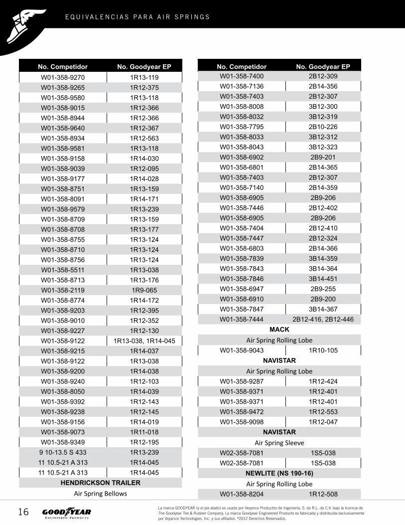
No. Competidor No. Goodyear EPNo. Competidor No. Goodyear EPW01-358-9270 1R13-119W01-358-9265 1R12-375W01-358-9580 1R13-118W01-358-9015 1R12-366W01-358-8944 1R12-366W01-358-9640 1R12-367W01-358-8934 1R12-563W01-358-9581 1R13-118W01-358-9158 1R14-030W01-358-9039 1R12-095W01-358-9177 1R14-028W01-358-8751 1R13-159W01-358-8091 1R14-171W01-358-9579 1R13-239W01-358-8709 1R13-159W01-358-8708 1R13-177W01-358-8755 1R13-124W01-358-8710 1R13-124W01-358-8756 1R13-124W01-358-5511 1R13-038W01-358-8713 1R13-176W01-358-2119 1R9-065W01-358-8774 1R14-172W01-358-9203 1R12-395W01-358-9010 1R12-352W01-358-9227 1R12-130W01-358-9122 1R13-038, 1R14-045W01-358-9215 1R14-037W01-358-9122 1R13-038W01-358-9200 1R14-038W01-358-9240 1R12-103W01-358-8050 1R14-039W01-358-9392 1R12-143W01-358-9238 1R12-145W01-358-9156 1R14-019W01-358-9073 1R11-018W01-358-9349 1R12-1959 10-13.5 S 433 1R13-23911 10.5-21 A 313 1R14-04511 10.5-21 A 313 1R14-045
HENDRICKSON TRAILERAir Spring Bellows
W01-358-7400 2B12-309W01-358-7136 2B14-356W01-358-7403 2B12-307W01-358-8008 3B12-300W01-358-8032 3B12-319W01-358-7795 2B10-226W01-358-8033 3B12-312W01-358-8043 3B12-323W01-358-6902 2B9-201W01-358-6801 2B14-365W01-358-7403 2B12-307W01-358-7140 2B14-359W01-358-6905 2B9-206W01-358-7446 2B12-402W01-358-6905 2B9-206W01-358-7404 2B12-410W01-358-7447 2B12-324W01-358-6803 2B14-366W01-358-7839 3B14-359W01-358-7843 3B14-364W01-358-7846 3B14-451W01-358-6947 2B9-255W01-358-6910 2B9-200W01-358-7847 3B14-367W01-358-7444 2B12-416, 2B12-446
MACKAir Spring Rolling Lobe
W01-358-9043 1R10-105NAVISTAR
Air Spring Rolling LobeW01-358-9287 1R12-424W01-358-9371 1R12-401W01-358-9371 1R12-401W01-358-9472 1R12-553W01-358-9098 1R12-047
NAVISTARAir Spring Sleeve
W02-358-7081 1S5-038W02-358-7081 1S5-038
NEWLITE (NS 190-16)Air Spring Rolling Lobe
W01-358-8204 1R12-508
2 0 1 4
17La marca GOODYEAR (y el pie alado) es usada por Veyance Productos de Ingeniería, S. de R.L. de C.V. bajo la licencia de The Goodyear Tire & Rubber Company. La marca Goodyear Engineered Products es fabricada y distribuída exclusivamente por Veyance Technologies, Inc. y sus afiliados. ®2012 Derechos Reservados.
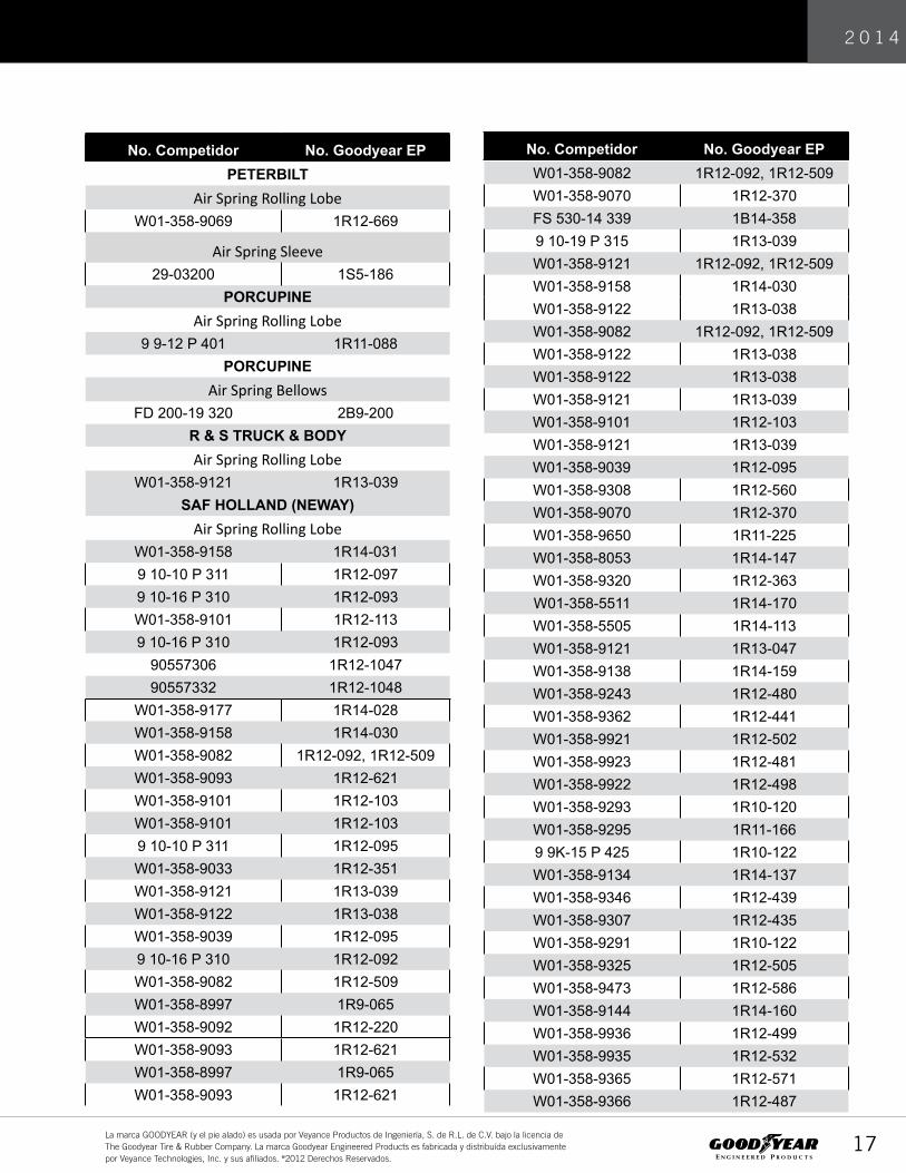
No. Competidor No. Goodyear EP No. Competidor No. Goodyear EPPETERBILT
Air Spring Rolling LobeW01-358-9069 1R12-669
Air Spring Sleeve29-03200 1S5-186
PORCUPINEAir Spring Rolling Lobe
9 9-12 P 401 1R11-088PORCUPINE
Air Spring BellowsFD 200-19 320 2B9-200
R & S TRUCK & BODYAir Spring Rolling Lobe
W01-358-9121 1R13-039SAF HOLLAND (NEWAY)
Air Spring Rolling LobeW01-358-9158 1R14-0319 10-10 P 311 1R12-0979 10-16 P 310 1R12-093W01-358-9101 1R12-1139 10-16 P 310 1R12-093
90557306 1R12-104790557332 1R12-1048
W01-358-9177 1R14-028W01-358-9158 1R14-030W01-358-9082 1R12-092, 1R12-509W01-358-9093 1R12-621W01-358-9101 1R12-103W01-358-9101 1R12-1039 10-10 P 311 1R12-095W01-358-9033 1R12-351W01-358-9121 1R13-039W01-358-9122 1R13-038W01-358-9039 1R12-0959 10-16 P 310 1R12-092W01-358-9082 1R12-509W01-358-8997 1R9-065W01-358-9092 1R12-220W01-358-9093 1R12-621W01-358-8997 1R9-065W01-358-9093 1R12-621
W01-358-9082 1R12-092, 1R12-509W01-358-9070 1R12-370FS 530-14 339 1B14-3589 10-19 P 315 1R13-039W01-358-9121 1R12-092, 1R12-509W01-358-9158 1R14-030W01-358-9122 1R13-038W01-358-9082 1R12-092, 1R12-509W01-358-9122 1R13-038W01-358-9122 1R13-038W01-358-9121 1R13-039W01-358-9101 1R12-103W01-358-9121 1R13-039W01-358-9039 1R12-095W01-358-9308 1R12-560W01-358-9070 1R12-370W01-358-9650 1R11-225W01-358-8053 1R14-147W01-358-9320 1R12-363W01-358-5511 1R14-170W01-358-5505 1R14-113W01-358-9121 1R13-047W01-358-9138 1R14-159W01-358-9243 1R12-480W01-358-9362 1R12-441W01-358-9921 1R12-502W01-358-9923 1R12-481W01-358-9922 1R12-498W01-358-9293 1R10-120W01-358-9295 1R11-1669 9K-15 P 425 1R10-122W01-358-9134 1R14-137W01-358-9346 1R12-439W01-358-9307 1R12-435W01-358-9291 1R10-122W01-358-9325 1R12-505W01-358-9473 1R12-586W01-358-9144 1R14-160W01-358-9936 1R12-499W01-358-9935 1R12-532W01-358-9365 1R12-571W01-358-9366 1R12-487

2 0 1 4
18La marca GOODYEAR (y el pie alado) es usada por Veyance Productos de Ingeniería, S. de R.L. de C.V. bajo la licencia de The Goodyear Tire & Rubber Company. La marca Goodyear Engineered Products es fabricada y distribuída exclusivamente por Veyance Technologies, Inc. y sus afiliados. ®2012 Derechos Reservados.
No. Competidor No. Goodyear EPNo. Competidor No. Goodyear EPW01-358-8748 1R13-152W01-358-8749 1R13-153W01-358-8802 1R12-434W01-358-8204 1R12-508W01-358-9473 1R12-586W01-358-9122 1R13-038W01-358-5503 1R14-174W01-358-9218 1R13-120
W01-358-8203, W01-358-9366 1R12-487
W01-358-9470 1R12-554W01-358-9471 1R12-5529 10-17.5 P 573 1R12-553W01-358-9471 1R12-485W01-358-9473 1R12-484W01-358-9504 1R12-486W01-358-8204 1R12-508W01-358-9366 1R12-487W01-358-8197 1R12-562
SAF HOLLAND (NEWAY)Air Spring Bellows
FD 330-22 363 2B12-425W01-358-9039, W01-358-7135 2B14-360
W01-358-7009 1B12-301W01-358-7424 2B12-300W01-358-7437 2B12-320W01-358-7400 2B12-309FS 530-14 339 1B14-358W01-358-7112 1B14-358W01-358-7146 2B14-355W01-358-6799 2B14-476WO1-358-8042 3B12-322W01-358-6943 2B9-250
SAF HOLLAND HITCHAir Spring Bellows
W01-358-7800 3B14-360SAUER
Air Spring Rolling LobeW01-358-9039 1R12-095
SAUERAir Spring Bellows
W01-358-7424 2B12-300
W01-358-7423 2B12-434
2B9-201SILENT DRIVE
Air Spring BellowsW01-358-8027 3B12-310
SUSPENSION INC.Air Spring Rolling Lobe
W01-358-9394 1R12-142VOLVO
Air Spring Rolling Lobe9 10-16 P 449 1R12-615W01-358-8829 1R12-615W01-358-9296 1R12-4009 10-16 P 449 1R12-6159 10-16 P 449 1R12-6159 10-16 P 449 1R12-615W01-358-9296 1R12-4009 10-14 P 312 1R12-069, 1R12-669W01-358-9270 1R13-119W01-358-9422 1R11-028W01-358-9101 1R12-103W01-358-9781 1R12-603W01-358-9039 1R12-095W01-358-9265 1R12-3759 10-16 P 407 1R12-090W01-358-9466 1R12-365W01-358-9321 1R12-335W01-358-9321 1R12-335
W01-358-9122, 8792 1R14-045W01-358-9219 1R12-1829 10-16 P 408 1R12-182W01-358-9219 1R12-182W01-358-9219 1R12-182W01-358-9219 1R12-182
VOLVOAir Spring Bellows
W01-358-7401 2B12-320W01-358-6905 2B9-206W01-358-7410 2B12-406W01-358-7145 2B14-354FD 530-22 374 2B14-354

2 0 1 4
19La marca GOODYEAR (y el pie alado) es usada por Veyance Productos de Ingeniería, S. de R.L. de C.V. bajo la licencia de The Goodyear Tire & Rubber Company. La marca Goodyear Engineered Products es fabricada y distribuída exclusivamente por Veyance Technologies, Inc. y sus afiliados. ®2012 Derechos Reservados.
Firestone Flex Member
Firestone Firestone Goodyear Air Spring Firestone Firestone Goodyear Air SpringMembrana Núm: � Núm: Núm: Membrana Núm: � Núm: Núm
113B-1 7112 1B14-3581T15S-6 9043 1R10-0891T15LP-5 9293 1R10-1201T15LP-5 9291 1R10-1221T15S-6 9073 1R11-0181T15L-1.5 9422 1R11-0281T15L-2 9447 1R11-0661T15L-2 9448 1R11-1501T15L-2 9457 1R11-1511T15L-2 9459 1R11-1521T15TM-1 5766 1R11-1611T15LP-5 9295 1R11-1661T15TM-1 9421 1R11-1711T15L-4 8919 1R11-1911T15L-2 9376 1R11-2001T15L-2 9377 1R11-2011T15L-2 9378 1R11-2021T15L-2 9387 1R11-2031T15L-2 8900 1R11-2041T15L-2 9476 1R11-2051T15LA-1 9617 1R11-2191T15LA-0 9618 1R11-2201T15LA-1 9622 1R11-2211T15LA-0 9625 1R11-2221T15MJ-6 9098 1R12-0141T15MJ-6 9098 1R12-0471T15M-6 9083 1R12-0661T15M-4 9069 1R12-0691T15M-6 9213 1R12-0901T15M-6 9082 1R12-0921T15M-0 9039 1R12-0951T15M-9 9101 1R12-1031T15M-6 9227 1R12-1301T15M-2 9302 1R12-1321T15M-9 9241 1R12-1421T15M-6 9392 1R12-1431T15M-9 9238 1R12-1451T15M-6 9096 1R12-1551T15M-9 9192 1R12-1671T15LC-2.5 9379 1R12-1781T15M-6 9219 1R12-1821T15M-6 9223 1R12-1881T15M-9 9349 1R12-1951T15LC-2.5 9566 1R12-2041T15LC-4.5 9568 1R12-2051T15M-6 9193 1R12-2201T15M-11 9321 1R12-2561T19�-5 9204 1R12-2651T15MT-8 9287 1R12-2741T15M-9 9130 1R12-2811T15�R-6 9780 1R12-3031T15M-2 9053 1R12-3091T15LC-2.5 9565 1R12-3241T15LC-4.5 9567 1R12-3251T15M-0 9031 1R12-3501T15M-0 9033 1R12-3511T15M-4 9010 1R12-3521T15M-2 9127 1R12-3551T15M-6 9194 1R12-3561T15M-9 9348 1R12-3571T15M-6 9096 1R12-358
1T15M-0 9077 1R12-3591T15M-11 9320 1R12-3631T15MT-6 9466 1R12-3651T15ML�-7 8944 1R12-3661T15MT-3 9640 1R12-3671T15M-4 9070 1R12-3701T15M�-10 9265 1R12-3751T15M-9 9203 1R12-3951T15M-6 9296 1R12-4001T15MT-8 9371 1R12-4011T15MT-8 9297 1R12-4021T15MT-8 9373 1R12-4031T15MT-8 9375 1R12-4041T15M-4 8802 1R12-4341T15M-6 8924 1R12-4361T15M-4 9797 1R12-4371T15M-4 8805 1R12-4381T15M-9 9346 1R12-4391T15M-6 9362 1R12-4411T15M-4 8806 1R12-4451T15M-9 9245 1R12-4461T15M-9 9243 1R12-4801T15M-8 9923 1R12-4811T15�-8 9473 1R12-4841T15�-8 9471 1R12-4851T15�-8 9473 1R12-4861T15M-2 9366 1R12-4871T15M-7.5 9921 1R12-5021T15�-8 9471 1R12-5041T15M-2 9325 1R12-5051T15M-2 8204 1R12-5081T15M-2 9078 1R12-5121T15M-7.5 9935 1R12-5321T15MT-8 9648 1R12-5381T15�-8 9471 1R12-5521T15�-8 9472 1R12-5531T15�-8 9470 1R12-5541T15M-0 8961 1R12-5551T15M-0 8964 1R12-5561T15M-0 8976 1R12-5571T15M-0 8986 1R12-5581T15M-0 9029 1R12-5591T15M-0 9308 1R12-5601T15M-0 9332 1R12-5611T15M-2 8197 1R12-5621T15M-2 8934 1R12-5631T15M-6 9026 1R12-5671T15M-9 8852 1R12-5681T15M-2 9365 1R12-5711T15M-11 9370 1R12-5801T19L-11 9122 1R13-0381T19L-7 9121 1R13-0391T15�-11 9250 1R13-1151T15�-11 9252 1R13-1161T15�-8 9275 1R13-1171T15�L�-10.5 9580 1R13-1181T15�M-4.0 9270 1R13-1191T19�-5 9218 1R13-1201T17CL-5 8710 1R13-1241T17BB-2 8729 1R13-1301T17B-11 8748 1R13-152

2 0 1 4
20La marca GOODYEAR (y el pie alado) es usada por Veyance Productos de Ingeniería, S. de R.L. de C.V. bajo la licencia de The Goodyear Tire & Rubber Company. La marca Goodyear Engineered Products es fabricada y distribuída exclusivamente por Veyance Technologies, Inc. y sus afiliados. ®2012 Derechos Reservados.
Firestone By Flex Member
1T17B-11 8749 1R13-1531T17CA-5 8709 1R13-1591T17CA-6.5 8713 1R13-1761T17CA-6.5 8708 1R13-1771T19L-7 9149 1R14-0181T19F-11 9156 1R14-0191T19F-7 9148 1R14-0261T19L-7 9177 1R14-0281T19L-11 9158 1R14-0301T19F-5 9215 1R14-0371T19F-5 9200 1R14-0381T19J-7 8050 1R14-0391T19J-6 8052 1R14-0421T19L-11 9122 1R14-0451T19F-12 5505 1R14-1131T19F-7 9961 1R14-1151T19F-14 9264 1R14-1271T19F-9 9134 1R14-1371T19J-6 8053 1R14-1471T19F-7 9164 1R14-1591T19F-7 9144 1R14-1601T19FC-6 8091 1R14-1711T19F-12 5503 1R14-1741T14F-4 5406 1R9-0381T14C-1 1R9-0651T14F-4 1R9-07022-1.5 7443 2B12-30522-1.5 7447 2B12-324228-1.5 7545 2B12-345228-1.5 7550 2B12-346228-1.5 7446 2B12-40222-1.5 7444 2B12-41622-1.5 7473 2B12-42822-1.5 7472 2B12-434228-1.5 7555 2B12-44022-1.5 7444 2B12-44621-2 6801 2B14-36521-2 6803 2B14-366233-2 7557 2B14-38320-2 6927 2B9-21820-2 6943 2B9-25020-2 6948 2B9-25120-2 6944 2B9-25220-2 6945 2B9-25320-2 6946 2B9-25420-2 6947 2B9-25519 7009 1B12-30120 6910 2B9-20020 6935 2B9-20120 6905 2B9-20620 6908 2B9-21020 6897 2B9-22920 6940 2B9-23020 6902 2B9-23920 6932 2B9-24620 6941 2B9-26521 7145 2B14-35421 7146 2B14-35521 7136 2B14-35621 7140 2B14-35921 7135 2B14-360
21 7123 2B14-36722 7424 2B12-30022 7408 2B12-30722 7400 2B12-30922 7405 2B12-31322 7185 2B12-31822 7409 2B12-31922 7401 2B12-32022 7410 2B12-40622 7404 2B12-41022 7181 2B12-41122 7183 2B12-41222 7180 2B12-42522 7406 2B12-42622 7429 2B12-42722 7423 2B12-43226 7325 2B8-55038 8008 3B12-30038 8010 3B12-30138 8018 3B12-30338 8006 3B12-30438 8027 3B12-31038 8033 3B12-31238 8032 3B12-31938 7994 3B12-32838 7995 3B12-32938 7996 3B12-335113 7103 1B14-350113 7105 1B14-351257 7795 2B10-226313 7808 3B14-354313 7838 3B14-356313 7839 3B14-359313 7848 3B14-360313 7847 3B14-367333 7846 3B14-451333 7850 3B14-452
Firestone Firestone Goodyear Air SpringMembrana Núm: Núm: Núm
Firestone FirestoneG oodyear Air SpringMembrana Núm: Núm: Núm

2 0 1 4
21La marca GOODYEAR (y el pie alado) es usada por Veyance Productos de Ingeniería, S. de R.L. de C.V. bajo la licencia de The Goodyear Tire & Rubber Company. La marca Goodyear Engineered Products es fabricada y distribuída exclusivamente por Veyance Technologies, Inc. y sus afiliados. ®2012 Derechos Reservados.
Información de Garantía.
Todos los Air Springs vendidos por Veyance de México, están garantizadoa como l ibres de defectos en manufactura y materiales; cuando estos se uti l izan exclusivamente para las apl icaciones a los que hace referencia nuestro catalogo de producto. Cualquier producto que sea reclamado deberá , bajo la aprobación de Veyance de México, ser retornado a nues -t ro almacén de distr ibución con cargo al cl iente por concepto de f lete. Veyance de México real izará las pruebas pert inentes, y determinará en su caso la reparación o remplazo de la pieza, según sea el caso.
La responsabil idad de Veyance de México no excederá, nunca, el valor de la pieza reclama-da como defectuosa.
Retorno de Producto.
Si algún Air Spring es sospechoso de tener algún defecto, debido a alguna fal la en materiales y/o manufactura, contacte a su Representante de Ventas para su inspeccióny/o autorización para regresar la pieza a nuestras instalaciones.
AIR SPRINGS
SUPER CUSHION® AIR SPRINGS PARA TRACTOS, TRAILERS Y AUTOBUSES.
Menos vibración que la experimentada con suspensión mecánica. Su carga está mejor protegida de los impactos y de la vibración.
¿Qué más puede pedir para ayudar a sus operadores a conducir en el caminocon comodidad y seguridad?

2 0 1 4
22La marca GOODYEAR (y el pie alado) es usada por Veyance Productos de Ingeniería, S. de R.L. de C.V. bajo la licencia de The Goodyear Tire & Rubber Company. La marca Goodyear Engineered Products es fabricada y distribuída exclusivamente por Veyance Technologies, Inc. y sus afiliados. ®2012 Derechos Reservados.
E Q U I V A L E N C I A S PA R A A I R S P R I N G S
La marca GOODYEAR (y el pie alado) es usada por Veyance Veyance de México, S. de R.L. de C.V. bajo la licencia de The Goodyear Tire & Rubber Company. La marca Goodyear Engineered Products es fabricada y distribuída exclusivamente por Veyance Technologies, Inc. y sus afiliados. ®2012 Derechos Reservados.

BASIC PRINCIPLES OF AIR SPRINGS
GENERAL DISCUSSION heat to dissipate. The higher temperature of the gas results in a higher gas pressure and, therefore, a higher spring rate. When the heat of compression is partially retained within the gas, a polytropic rate results. This occurs during most normal spring deflections and produces neither isothermal nor adiabatic rates, although in typical use it is much closer to the adiabatic situation.
The pneumatic (air) spring is basically a column of confined gas in a container designed to utilize the pressure of the gas as a force medium of the spring. The compressibility of the gas provides the desired elasticity for suspension use. The air spring’s ability to support a mass depends upon its effective area, which is a nominal area found by dividing the load supported by the spring, by the gas pressure at any givenposition. The effective area is a function of the outside diameterof the flexible member and, for rolling lobe varieties, the outside diameter of the piston. Whether the effective area remains constant, increases, or decreases during deflection is governed by the design of the spring and its components. The spring rate is the result of change in effective area and the change in gas pressure as the spring is deflected. The gas pressure varies with the speed and magnitude of deflection; for a unit of deflection, the pressure and therefore, the spring rate will be different for isothermal, adiabatic, or polytropic processes. Air springs provide an adjustable spring rate, adjustable loadcarrying ability, simplicity of height control, and low friction. They are adaptable for light or heavy suspension applications.
3. LOCKED-IN SYSTEM Air springs which are not connected to a gas source with height control or other valve arrangements are often called Locked-In systems. In a locked-in system, air springs use a fixed mass ofgas as the elastic medium. A given amount of gas is sealed in the system, and remains constant for all conditions of load or deflection. As the load on a “locked-in” air spring increases, the gas vol-ume is reduced and the spring rate increases. Conversely, when the load on the spring is reduced, the gas expands and the increased gas volume results in a reduced spring rate. Thus, the natural vibration frequency of a suspension system using an airspring with the air locked-in generally increases as the load on the system increases.
4. ACTIVE-AIR SYSTEM 2. COMPRESSION PROCESSES
Air springs which are connected to a constant source of air through a height control or other valve arrangement are often referred to as being part of an “Active-Air” system.
For a specific spring design, the minimum air spring rate occurs under isothermal compression conditions and the maximum spring rate occurs with adiabatic compression. The polytropic rate varies between the isothermal and the adiabatic. The isothermal rate results when all the heat of gas compression escapes so that the gas remains at a constant temperature. The isothermal rate is approached when the spring is deflected very slowly to allow time for the heat to escape. The gas temperature remains constant, and the gas pressure rise is minimal.
The air springs maintain a relatively constant volume at a given operating height regardless of static load or gas pressure. This is the more common system in use at this time. At a given height, the load-carrying ability and the spring rate are variedby changing the pressure of the confined gas. With this type ofsystem, an external source of compressed gas is needed to maintain the spring height as the load on the spring is changed. The natural vibration frequency of the constant volume air spring remains more uniform with changes in load than does the natural frequency of air springs in a locked-in system.
Adiabatic rate occurs when all the heat of compression is retained within the gas. This condition is approached during rapid spring deflection when there is insufficient time for the

5. SPRING CHARACTERISTIC FEATURES SPECIFIC TO AN ACTIVE-AIR SYSTEM Effective static deflection is determined by the dynamic rate at the static design position. It can be shown graphically by drawing a line tangent to the dynamic load-deflection curve at the static design position and extending it through the zero load line, then measuring the distance back to the static design position. (See Fig. 2.1.) Natural frequency is directly related to the effective static deflection.
Spring rates vary in direct proportion to the force. The natural frequency of the system stays reasonably constant throughout the normal force range.
Figure 2.2 shows the effect of piston shape on the effective area (A
e) and on the dynamic force (F
d) curves versus spring
position. The three figures (2.2a, 2.2b, and 2.2c) show the same rolling lobe flexible member with different piston types. The graphs demonstrate what effect the piston shape has on spring characteristics.Figure 2.2a shows a straight wall piston which has a neutral effect on the effective area and spring force. The effective area curve (A
e) is essentially flat, and increases only slightly as the
spring compresses. The spring force (Fd) increases as the spring
is compressed due to the increase in pressure.
System natural frequencies may vary by spring design, spring volume, and spring position within the system.
Figure 2.2b shows a back tapered piston which allows for the lowest spring rate. The effective area varies due to the shape ofthe piston. It decreases as the spring compresses, until the bottom flare of the piston takes effect, at which time, the effective area begins to increase. The force to compress also decreases over the back tapered portion of the piston, andincreases again as the piston flares out which prevents rapidcompression and bottoming out. Figure 2.2c shows a positive tapered piston. This style of piston provides the highest spring rate. Both the effective area and spring force increase rapidly as the spring compresses.

6. BASIC CYLINDER AND PISTON SPRINGS 9. GAS LAW PROCESSES
(3) Clevises are required at the top and bottom for most mountings.
Cylinders with pistons can be used as pneumatic springs but they have several major drawbacks: (1) Sliding friction transmits significant forces through the spring. Short impulses are especially detrimental. (2) It is difficult to maintain zero gas leakage past the piston and rod seals for the desired life of the unit.
(4) The effective area cannot be manipulated. (5) The piston and rod guide present wear problems. An advantage is that high operating pressures may be used, and the unit can combine load-carrying and damping functions.
A. Definitions–Units The mass of a vehicle and of its cargo is measured in pounds-mass (lbm) and is usually called “weight”; this mass, less the unsprung mass, acts upon the suspension springs as a load, or more accurately as a vertical downward force F (now designated ‘force of gravity’), equaling mass times accelerationof gravity and measured in pounds-force (lbf). It is generally accepted that the terms pounds-mass (lbm) and pounds-force (lbf) are interchangeable. Both are usually referred to as pounds (lb).With an air suspension spring, the load is supported by a force which is developed as the product of gas pressure and the effective area within the air spring.
7. BASIC DESIGN CONSIDERATIONS In this manual the force is measured in pounds, the gas pressure is measured in pounds per square inch (that is, the pressure above atmospheric pressure), and the effective area is measured in square inches.
The flexible member structure carries only a portion of the developed spring force, with the remainder being transmitted directly through the gas column to the rigid supporting mem-bers. Stress is imposed upon the flexible member by both the internal air pressure and, in the case of the rolling lobe type airspring, by the piston contour. High initial stresses and severe fluctuations in stress result in reduced durability. Air spring designs which have the lowest maximum stress and low stress variation with cycling will achieve the best durability. Durability is also directly coupled with imposed stress which are the result of the suspension design. GoodyearEngineered Products by Veyance Technologies, Inc.recommends that the nominal internal design pressure not exceed 100 PSIG. However, more conservative operating pressures will generally result in increased life. To maintain their correct shape, air springs should have at least slight positive internal pressure under all deflection conditions. When flexed with no positive internal pressure, rolling lobe airsprings may fold between the piston and the top mounting metals, resulting in pinching and/or rupture of the flexible member. Generally, 10 PSIG minimum pressure will prevent operation troubles. In some cases, half this pressure will suffice, but in a few special cases up to 20 PSIG may be required.
F(lb) = P(PSIG) x A e (in²)
The pressure of the atmosphere at sea level is in balance with a 29.9 inch column of mercury at 32˚F; it equals 14.7 PSIG. The sum of the atmospheric pressure. The fundamental gas laws deal with this absolute pressureB. Vertical Supporting Force As shown above, the supporting force (F) is created as the product of gas gauge pressure and effective area: F = P x A
eEffective area (A
e) can be found directly when the force and
pressure are known. Then it is the result of dividing force by pressure. C. Constant Pressure, No Gas Flow, Constant Effective Area With Constant Pressure:
2
1
2
1
2
2
1
1
TT
VVor
TV
TV
==
where: T = absolute temperature V = total pneumatic spring and auxiliary volume These relationships affect the air spring system when the system is at rest and only temperature changes occur. Dynamically, the only way to maintain constant pressure is in combination with infinite volume and thus is not generally useful.
8. BASIC CALCULATION CONSIDERATIONS The basic gas laws apply for design calculations of general characteristics in the pressure, temperature, and natural fre-quency ranges normally used by air springs. In addition to these factors, an effective area varying with deflection must frequently be considered. This can be accomplished by changing the size or shape of the piston. The basic gas laws apply for design calculations of generalcharacteristics in the pressure, temperature, and natural fre-quency ranges normally used by air springs. In addition to these factors, an effective area varying with deflection must frequently be considered. This can be accomplished by changing the size or shape of the piston.
D. Constant Volume, Non-Flow Process This process (see Fig. 2.3) can be shown as:
2
2
1
1TP
TP =
where: P = absolute pressure T = absolute temperature From a practical standpoint, with true gasses this is a desirable but unattainable process because of the nature of the flexible member. Extremely large volumes may allow an approximation of the process and there are ways to obtain small ratios ofvolume change to total volume with feasible total volumes. (An example, interconnecting springs with only one spring undergoing a volume change at a time.)
It may also be necessary to take into account the fact that a nonproportional change in volume may occur during deflection.

E. Constant Temperature, Non-Flow Process (Isothermal Process)
G. Polytropic, Non-Flow Process (Normal Pneumatic Spring Operation)
P1 x V1 = P2 x V2
n
VV
PPn
VVnn
PP
TT or
2
1
1
2
2
1
1
2
1
2)1(/)1(
===−−
where: P = absolute pressure V = total volume PV = constant where: T = absolute temperature
P = absolute pressure V = total volume
n = polytropic exponent This process (see Fig 2.4) must be taken into account when examining the static stability of systems. It determines the practical limit of low rate operation. Under isothermal conditions, the spring rate must be appreciably in the positive range.
This is the general case where the terms pressure, volume andtemperature all vary (see Fig. 2.6) Air springs operate in the full range from nearly isothermal to almost adiabatic. A generally acceptable value for n is 1.38 when the natural frequency of the system is being determined.
F. Adiabatic, Non-Flow Process: This is defined as a processwith no heat transferred to or from the working fluid (see Fig. 2.5).
where: T = absolute temperature P = absolute pressure V = volume δ = adiabatic exponent
1/)1(
2
1
1
2
1
2−−
==δδδ
VV
PP
TT
This is a theoretical process; in practice it is not attainable with air springs. However, for rapid deflections it is closely approached.

AIR SPRING TYPES
1B SINGLE CONVOLUTE – BELLOWS * SLEEVE TYPE * CRIMPED
2B DOUBLE CONVOLUTE – BELLOWS * SLEEVE TYPE * CRIMPED
3B TRIPLE CONVOLUTE – BELLOWS * CRIMPED
1S SLEEVE TYPE ROLLING LOBE * SLEEVE TYPE
1R CONVENTIONAL ROLLING LOBE
*CRIMPED

PRODUCT IDENTIFICATION SYSTEM
Elements of the part identification system are shown in the following example for ordering an assembly with the part number 2B12-300.
Number of convolutions in the assembly: 1 – Single convolute 2 – Double convolute 3 – Triple convolute
2 B 12-300
Refers to the type of air spring: B – Bellows R – Rolling lobe (bead type conventional) S – Sleeve (beadless rolling lobe type)
The nominal outside working diameter of the air spring assembly, in inches
The three digits that represent a unique identifier for this particular air spring

PRODUCT DESCRIPTION
Rolling Lobe Air Spring Rolling lobe air springs incorporate a piston which allows the flexible member to roll along the piston’s surface.
Sleeve Type Rolling Lobe Sleeve type rolling lobe air springs employ a flexible member without an internally molded bead. The flexible member is attached to the end retainers by pinching the material between the end retainers and exterior crimp rings which are then swaged to the properdiameter.
Upper Bead Plate
Rubber Bumper (Optional)
Flexible Member
Lower Retainer
Piston
Blind Tap
Air Inlet/Mounting Stud Combination
Mounting Stud
Air Inlet / MountingStud Combination
Upper Retainer
Crimp Ring
Crimp Ring
Piston
Mounting Stud
Flexible Member

Sleeve Type Bellows Sleeve type bellows offer similar characteristics to the crimped design bellows, but, as with the sleeve type rolling lobe the flexible member is constructed without internally molded bead wires. The end retainers are permanently attached by pinching the flexible member between the end retainers and external crimp rings which are then swaged to the proper diameter.
Sleeve type bellows offer the lowestforce to compress of any type of airspring.
Bellows Type Air Spring Bellows air springs have one, two orthree convolutions in the flexible member. There are two styles ofbellows; crimped design and sleeve type.
With the crimped design, the end retainers are permanently attached by mechanically crimping the retaineraround the built-in bead wire of the flexible member.
Upper BeadPlate
Flexible Member
Rubber Bumper(Optional)
Air Inlet
Blind Tap Girdle Ring
Blind Tap Lower Bead Plate
Air Inlet
Blind Tap Upper Retainer
Crimp Ring
Girdle Ring
Crimp Ring
Rubber Bumper (Optional)
Blind Tap Lower Retainer
Flexible Member

SUPER-CUSHION® AIR SPRINGCOMPONENTS
FLEX MEMBERS Super-Cushion® air spring flex members are built of two plies of either nylon or polyester fabric, coated with rubber. They are designed to withstand inflation pressure, frequent flexing and misalignment. The rubber cover protects against abrasion, aging and the external environment. A rubber liner protects against the interior environment and loss of air. The elastomerused in Super-Cushion air springs can be a natural rubbercompound or Wingprene®.The majority of vehicular Super-Cushion air springs are made of natural rubber for durability and low temperature capability. Wingprene springs are available for special applications where excessive exposure to oil may exist. Contact Veyance Technologies, Inc. for details.
RETAINERS The purpose of the upper and lower retainers is to attach to the flexible member of the Super-Cushion air spring, thus creating an air tight seal. All retainers and pistons are made of an engineered thermoplastic or thermoset composite material; or corrosion resistant aluminum, zinc or steel.
END COMPONENT OPTIONS
Upper and lower retainers are made with blind taps, or protruding bolts to facilitate attachment. The upper retainer has a tap to accommodate a 1/4", 1/2" or 3/4" air fitting or valve. Although it is called the upper retainer for reference, it need not be in the up position to function properly; the attitude of the airspring does not affect its function.
BUMPERSA rubber bumper inside the air spring assembly helps protect the flexible member and the end retainers in those applicationswhere external compression stops are not practical. Internal bumpers are recommended when: 1. The assembly will frequently reach the “compressed height without a bumper.”* 2. The assembly will occasionally reach the “compressed height without a bumper,”* but with a significant load and impact. 3. A vehicle may have to operate on a deflated air spring assembly. *See Glossary and/or Selection Charts
1. CRIMPED ON RETAINERSAvailable for springs: -1B9 and larger Bellows -2B9 and larger Bellows -3Bl2 and larger Bellows -1R8 and larger Rolling Lobes Upper and lower retainers are attached by mechanically crimping the retainer aroundthe bead wire built into the flexible member.
2. SWAGED ON RETAINERSAvailable for springs: -1B5 thru 1B8 Bellows -2B6 thru 2B8 Bellows -All 1S Sleeve Type Rolling Lobes Upper and lower retainers are permanently attached by swaging a metal ring around the flexible member and end retainer.
3. BOLTED BEAD RINGIn certain applications, used in place ofcrimped on retainers. Available for springs: -lB9 and 2B9 Bellows -1Bl 2, 2Bl 2 and 3Bl 2 Bellows -2Bl9 and 2B22 Bellows Upper and lower bead rings are attached by bolting each to the customer's own mounting plate. An air tight seal is formed when all bolts are securely fastened through the beadring into the mounting plate.
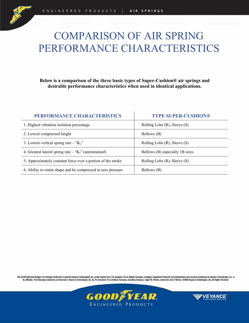
COMPARISON OF AIR SPRING PERFORMANCE CHARACTERISTICS
Below is a comparison of the three basic types of Super-Cushion® air springs and desirable performance characteristics when used in identical applications.
PERFORMANCE CHARACTERISTICS TYPE SUPER-CUSHION®
1. Highest vibration isolation percentage Rolling Lobe (R), Sleeve (S)
2. Lowest compressed height Bellows (B)
3. Lowest vertical spring rate – “Kv” Rolling Lobe (R), Sleeve (S)
4. Greatest lateral spring rate – “Kl” (unrestrained) Bellows (B) especially 1B sizes
5. Approximately constant force over a portion of the stroke Rolling Lobe (R), Sleeve (S)
6. Ability to retain shape and be compressed at zero pressure Bellows (B)

E n g i n E E r E d P r o d u c t s A I R S P R I N G S
The GOODYEAR (and Winged Foot Design) trademark is used by Veyance Technologies, Inc. under license from The Goodyear Tire & Rubber Company. Goodyear Engineered Products are manufactured and sourced exclusively by Veyance Technologies, Inc. or its affiliates. ©2008 Veyance Technologies, Inc. All Rights Reserved.
Air springs have successfully solved actuating problems, at a reduced cost, in many applications including:
• Injectionorejectionofpartsinmanufacturingprocesses• Tensioningdevicesforcables,calendarrollsandconveyors• Forcedevicesfordiecuttingandstamping• Positioningdevicesinmanufacturingprocesses• Clampingdevicesforwoodgluers,etc.• Verticalliftforceforplatformsandforrotationtables• Rotaryshaftactuators• Doubleactingactuatorsforstitchingmachines• Drainvalveactuators• Actuationtoengageanddisengagepoweronpoweredrollerconveyor• Powersourceindirect-actingformingpress(metalandplastics)• Powersourceincompactors• Powersourceinlaminatingplywoodpresses• Graniteslabpositioners• Palletlifts• Liftactuatorsfordiagnostictablesinhospitals• Reciprocatingshaftseal• Underwateractuatorforgatecontrols• Lumberpositioneractuatorsinsawmills• Actuatorsforconcreteblockmachinery• Directional-changeactuatorsinrollerconveyingsystems• Actuatorsforflaskliftsonfoundryshake-outs• Actuatorsonbottleandcartonfillingmachines• Bin-tiltingactuators(foreaseofaccess)• Actuatorsontransfertables• Actuatorsinsandblastrooms• Actuatorsinglassgrindingrooms• Industriallaundryequipmentactuators• Energystoragedeviceactuators• Canformingactuators(beverageandfuelindustries)• Car/truckfrontendalignmentrackactuators
Industrial Air Spring Application • Actuation

E n g i n E E r E d P r o d u c t s A I R S P R I N G S
The GOODYEAR (and Winged Foot Design) trademark is used by Veyance Technologies, Inc. under license from The Goodyear Tire & Rubber Company. Goodyear Engineered Products are manufactured and sourced exclusively by Veyance Technologies, Inc. or its affiliates. ©2008 Veyance Technologies, Inc. All Rights Reserved.
Air springs have solved vibration and noise problems in multiple applications, such as:
• Vibratingshakerscreens• Vibratingconveyors• Vibratinghoppersandbins• Isolationofflextestingmachines• Isolationofforginghammers• Isolationoffrozenfoodandplasticpelletcompactionsystems• Isolationofcabsondredgingmachines• Isolationofcomputerandspectrometersfromoutsidevibration• Isolationofoscillatingequipment• Isolationofsensitiveequipment(laserbench)orsensitive
machinecontrols• Jetenginetestingplatforms(isolationandthrustabsorption)• Industrialsuspensionsystems• Largedryingmachines(milkdryers)• Foundryshake-outsystems• Centrifugalseparators• Scalesandweightcontrolequipment• Presses• Compressors,fansandblowers• Textilelooms• Reductionofseverimpactandeliminationofimpactidlersat
conveyorloadpoints• Seatsuspensions• Industrialwashingmachines• ProtectionofPolarisandAtlasrocketsinstorage,ground
handlingtransit• Coordinatemeasuringtablesandmachinery• Replacementofsteelspringsforbettervibrationisolation,
heightcontrolorheightadjustment
Industrial Air Spring Application • Vibration Isolation

GLOSSARY
AAir Actuator A device which induces action or motion with compressed air being the
medium through which the power is transmitted, similar in function to a hydraulic cylinder.
Air Spring Assembly An air spring flexible member complete with end closure components (retainers) ready to be mounted in place and used as an air actuator or vibration isolation mount.
Amplification Act of amplifying; increase; enlargement.
Amplitude The extent of a vibratory movement, the range of a fluctuating quantity from the average or mean position to an extreme.
Amplitude of Force Oscillation The distance from the spring static design height to either extremity of an oscillation.
Auxiliary Volume All volume added to the spring system beyond that included in the basic spring at the selected spring static design height as shown on the load vs. deflection at constant pressure graph for that spring.
Axle Gross Mass Rating The axle’s share of the vehicle’s design rated capacity at the base of the tires.
Axle Sprung Mass Axle gross mass less the axle unsprung mass.
Axle Travel The distance the axle can move away from the static design position. It can be in the extension or compression direction, but must be labeled properly.
Axle Unsprung Mass The mass of all the suspension and running gear components not supported by the pneumatic springs.

BBead Wire A solid or flexible wire molded into each end of a flexible member, except in a
sleeve-type flexible member. It permits the end retainers to be attached to the flexible member to create an air tight seal for rolling lobe and bellows type assemblies
Bellows An air spring having one, two or three convolutions in the flexible member.
Blind Tap Attachment provision recessed in the retainer, closed at the bottom to prevent air loss. A bolt or shoulder-stud can be inserted to attach the air spring to machinery.
Bolted Bead Ring A ring used to attach certain bellows type flexible members to the mounting surface. Used in place of the conventional upper and lower crimped-on retainers.
Bumper An internal compression stop. Generally a molded rubber part attached inside the air spring assembly. It aids in preventing internal damage to the air spring assembly due to heavy loads coupled with severe compression and helps to prevent damage in the event of air loss.
CConvolution On a bellows type air spring, that part of the flexible member forming an
annular protrusion larger than the O.D. of the end retainers or the girdle ring(s).
Cover The external layer of elastomer which protects the reinforcing cords from abrasion, weathering, or other undesirable effects.
Crimped Design That type of air spring assembly in which the flexible member is permanently attached to the upper retainer by crimping the upper and lower retainers around the bead wires molded into the flexible member.
Crimp Ring A solid metal ring used to attach a sleeve or molded sleeve bellows type flexible member between the crimp ring and the end retainer.
CPM (Cycles per minute): A unit of measure of the frequency of any vibration.

DDeflection: The amount of increase or decrease in the spring length from the spring static
design height. It must be properly labeled as extension or compression.
Design Conditions: The motionless (static), position or condition, of the vehicle and all its components as stipulated in the design.
EEffective Area: A specific area found by dividing the load supported by the air spring by its
internal gas pressure at any given spring position. The effective area of the rolling lobe and sleeve type assemblies is more constant over the stroke than that of a bellows. However, all air spring generally have decreasing effective areas with extension.
Effective Diameter: A function of the effective area. The effective diameter is always less than the actual diameter of the air spring.
Effective Static Deflection: Obtained by extending a line tangent to the dynamic load deflection curve at the selected spring static design position down to the zero force line, and measuring the horizontal distance along this line separating this intersection and the vertical line defining the spring static design position.
FFlexible Member: The rubber-fabric component in an air spring assembly consisting of special
reinforcing cords sandwiched within rubber.
Forced Frequency (ff): The number of oscillations per unit time of an external force acting on a mass. Sometimes referred to as the disturbing or exciting frequency and measured in CPM or Hertz. Also see Natural Frequency.
GGirdle Ring: A rubber covered bundle of wires that restricts the diameter of the flexible
member at the attachment point to form double or triple convolutions.
HHeight A dimension always measured linearly along the stroke of an air spring
assembly between the parallel planes of the attachment surfaces of the upper retainer and lower retainer.a. Bumper Contact Height: That height at which the bumper contacts the opposite retainer. b. Compressed Height: That height at which the deflection of the air spring assembly must be limited by external means to prevent possible damage to the air spring assembly. This is the shortest height shown on the load vs deflection graph and applies to any portion of the top and bottom mounting surfaces. It is not necessarily the eight measured at the longitudinal center line of the spring. Also referred to as “Compressed Height without a Bumper”. c. Design Height: The selected operational height of an air spring when mounted and inflated with the mass at rest. d. Design Height Range: A predetermined range of heights within which the design height should be selected for optimum performance.e. Height Limit (Actuator): The extension limit of the air spring assembly. A reduction in life is probable above this limit due to the repetition of highly concentrated stresses. Extension restraints are required. f. Maximum Extended Height: The maximum operational height of the air spring assembly. Exceeding this height may result in structural damage to the air spring assembly. Extension restraints are required. g. Metal to Metal Height: That height where the air spring assembly is compressed to the point where the metal or plastic retainers contact.
Height Control Valve A device which controls the distance between a selected location on the sprung mass and the axle or other unsprung suspension component.
Hertz Cycles per second (Hz) - a unit of measure of the frequency of any vibration.
IIsolator (Vibration) A device used to join one object to another, and restrict the transmission of
vibration to some degree.
JJounce The compression of the suspension or air spring below its design height.

LLaterally Restrained Rolling Lobe A rolling lobe type air spring with the flexible member contained by a rigid
cylinder attached to the mounting plane opposite the piston for lateral stability.
Lever Arm The distance from the spring centerline to the centerline of the pivot point.
Lever Arm Ratio The spring arm distance from the attachment to the frame divided by the wheel axle arm distance from the attachment to the frame (Ds/Dw).
Liner The internal layer of elastomer which provides resistance to gas permeability.
Load The vertical downward force imposed by the mass.
Load Range That range of loads which the air spring assembly can support with an inflation pressure at, or below, 100 PSIG and within the design height range.
MMaximum Inflated Diameter (Max O.D.)
The largest diameter the air spring assembly will attain at an internal pressure of 100 PSIG or less, including a factor for growth over time.
Meniscus That portion of the flexible member of a rolling lobe or sleeve type air spring that curves under (reverses) in the transition from working diameter to the piston diameter.
Meniscus Height (M) The distance measured from the bottom of the meniscus to the bottom of the piston. Applies to rolling lobe and sleeve type air spring assemblies only.

NNatural Frequency (fn) The number of cycles per unit time that a mass vibrates on its spring medium.
Usually considered only in the vertical mode and expressed in Hertz (cycles per second) or CPM (cycles per minute).
Nominal Outside Working Diameter This is the one or two digit number that follows the R, S or B in the product description. It is the approximate working diameter of the Super Cushion air spring.
NPTF American National Standard Dryseal Pipe Threads. N=National (American) Standard, P=Pipe, T=Taper, F=Fuel or oil. Veyance Technologies, Inc. recommends always using a suitable thread sealant, such as Teflon tape, for additional leak protection.
OOrifice Area The cross-sectional area of an orifice opening separating the basic spring
volume from the auxiliary system volume.
PPercent Vibration Isolation That percent of the forced frequency isolated by the air spring.
Piston A rigid structure over which the flexible member rolls. The contour of the piston affects the operating characteristics of the air spring assembly.
PSIA Pounds per square inch, absolute.
PSIG Pounds per square inch, gauge. The pressure measured by a gauge within a closed system. Zero PSIG = 14.7 PSIA at sea level.

RRadial Clearance The minimum distance from the spring wall to nearby vehicle components.
This must allow for all extreme pneumatic spring dynamic conditions.
Rebound The extension of the suspension or air spring above its design height.
Reinforcement A structure of cords built into the flexible member to control its shape and strengthen its wall structure against internal gas pressure. Normally this is two bias plies of synthetic cord.
Rolling Lobe Rolling lobe air springs incorporate a piston which allows the flexible member to roll along the piston’s surface as forces change. Also referred to as a “piston-type” air spring.
Resonance The phenomenon shown by a vibrating system which responds with maximum amplitude under the action of a harmonic force. Resonance occurs when the forced frequency is the same as the natural frequency of the vibrating body.
Restraining Cylinder A rigid cylinder attached at one end to the plane of the mounted mass. When dimensionally matched to restrain the O.D. of the air spring, it also provides additional lateral support. It can eliminate the need for more elaborate stability arrangements.
Retainer The end enclosure of an air spring assembly. Two retainers are used in each air spring assembly. Generally made of metal and supplied with blind taps, protruding bolts, or a combination of these to facilitate mounting the assembly to equipment a. Upper Retainer: Refers to that retainer which usually contains the air fitting. It need not be in the up position. b. Lower Retainer: Refers to that retainer with no air fitting. In a bead type rolling lobe assembly, the lower retainer extends through or attaches to the piston.

SShoulder Stud A threaded bolt with a shoulder that can only be driven a specified depth into a
blind tap. The shoulder limits the depth and prevents fracture of the bottom of the blind tap.
Sleeve An air spring flexible member manufactured without internal bead wires.
Sleeve Type Assembly A rolling lobe type assembly utilizing a flexible member without internally molded bead wires.
Spring Force The force generated by the air spring which opposes the applied force of the sprung mass.
Spring Rate (K) The change in load per unit of deflection. a. Vertical Spring Rate (Kv): Measured along the axis of the air spring assembly. b. Lateral Spring Rate (Kl): Measured perpendicular to the axis of the air spring assembly.
Spring Rate (Wheel) The end result of the spring rate calculations after the suspension arm ratio is applied to the spring rate.
Spring Volume The volume inside the flexible member and connecting inside spaces in the top and bottom attached components.
Stroke (Total) The difference between the maximum extended height and the compressed height.
Stud A threaded bolt that can be permanently attached to the retainer or inserted into a blind tap in the retainer. Also see Shoulder Stud.
Swaged Design That type of air spring assembly in which the flexible member is permanently attached to the end retainers with crimp rings. The flexible member is compressed between the end retainer and crimp ring by mechanically reducing the diameter of the crimp ring.
TTank Valve A tire type inflation valve which can be used with an air spring assembly for
manual inflation.
Transmissibility The ratio of transmitted force to exciting force.
UUNC Unified national coarse (thread).
UNF Unified national fine (thread).
WWheel Force The force acting at the wheel contact point and the ground resulting from the
suspended mass acting through the various suspension system components.

B. Bellows Type Air Springs For maximum compression stroke, the end retainers should be parallel in the fully compressed position, as shown in Fig. 5.4. Be sure that a line drawn through the pivot point andperpendicular to the air spring assembly centerline also di-vides the air spring in half.
However, Fig. 5.3 shows the range of positions in a more realistic situation. Because the air spring travels in an arcute path, the piston and upper retainer may not have the same center line at either design height or at compressed height. Also, the maximum horizontal displacement away from the pivot arm should be less than the maximum displacementtoward the pivot arm.
Suspension basic style and geometry are not considered here. A. Rolling Lobe Air Springs Figs. 5.1 and 5.2 show that the piston in a fully compressed position has the same centerline as the upper retainer. These figures show an ideal situation which allows ample internal clearance and full bumper contact.
1. DESIRABLE AIR SPRING MOUNTING GEOMETRIES
The versatility of air springs in vehicular suspensions leads the designer to new and different approaches in his designs. Tips on what is known to work best with regard to the air springs are discussed herein. Some of the conditions which are known to adversely affect the life of air springs are also presented. The basic concept in all the desirable mounting geometries is to minimize the peak cord or bond stresses. Also, pinching andrubbing reduces air spring life and must be avoided.
PHYSICAL APPLICATION CONSIDERATIONS

The end retainers may be parallel at the design height if ade-quate compression stroke can be obtained. But the previous statement always applies. The centerline of the lower retainer and the upper retainer should coincide in the fully compressed position. C. Parallelogram Suspension Linkage The centerline of the piston should move equal distances fore and aft of the upper retainer centerline when the piston is moved through its full travel. The normal design position is shown in Fig. 5.5.
2. UNDESIRABLE AIR SPRING MOUNTING GEOMETRIES
The examples mentioned in this section are extreme cases. Pneumatic springs are capable of long operation with much abuse, but poor operating geometries will result in earlier fail-ures than springs used with good geometries. Rather small changes in operating geometries on long stroke life tests can show 4-10 times life improvement with improved geometries. Field operations will probably not show as dramatic life improvements because of fewer long strokes in service, but certainly the trend toward improvement will be there. Avoid centerline offset as is illustrated in Fig. 5.7. The rolling lobe type is less sensitive to misalignment than the bellows.
D. Multi-Axle Pneumatic System With a multi-axis arrangement, it is possible to connect all the springs on each side of the vehicle or trailer to a common air supply after it has been through the height control valve (see Fig. 5.6). It is best to have the maximum size tubing practical for the application connecting all springs in such a system. The advantages are that as an individual spring flexes, all the other springs act as reservoirs, thus reducing the pressure change andthe dynamic spring rate of that spring. The somewhat increasedpressure in the other springs has only a mild effect on their spring rate and the shock to the vehicle is damped, reduced, anddistributed over a greater area. This arrangement does not affect vehicle roll stability.

Fig. 5.8 shows piston centerlines improperly related to the pivot arm. There will be increased wear at the upper mounting plate and on the sleeve where it rolls on the piston, plus the possibility of internal rubbing.
Fig. 5.10 shows an air spring under low pressure conditions which may cause it to buckle and fold when compressed and may be damaged in the fully compressed positions. It will wear internally, causing reduced life.
The lower mounting designs shown in Fig. 5.9 are unstable and unnecessary if other proper design criteria are employed.

AIR SPRING APPLICATION CONSIDERATIONS FOR COMMERCIAL
VEHICLES This section is devoted to bridging the gap between the theo-retical characteristic of air springs and their functional appli-cation. Recognizing that the usual application of these springs will be in conjunction with other components making up a vehicle suspension, examples are presented here in terms of the air spring design for actual suspension systems. From this presentation, the designer should be able to determine the sequence of data accumulation, analysis, and calculation required to arrive at a suitable design within his particular parameters. He should also gain an understanding of how the air spring characteristics, discussed in earlier chapters, become pertinent to overall suspension design. In addition to the design procedure examples and calculations, a section of this chapter presents generalized considerations for air spring suspension design which have evolved from the experience of suspension designers and air spring manufacturers. The advantages of pneumatic suspension are not automatically attained. The entire suspension must be properly designed if it is to take full advantage of air spring capabilities and to compensate for their few limitations.
The system requirements that the spring is to supply are as follows:
1. Satisfactory mechanical operation over the full axle travel. 2. Support for the sprung mass with the available air pressure. 3. The desired dynamic spring rate and system natural fre-quency throughout the sprung mass load range. 4. Desirable or at least satisfactory dynamic force character-istics throughout the full axle travel. The air spring requirements that the suspension system must provide are as follows: 1. A space envelope that allows the spring to function properly at all heights. 2. An operating environment that does not seriously affect spring life. To take maximum advantage of these possibilities, many considerations should be kept in mind. There is reserve ca-pability and versatility built into air springs. While some viola-tions of the following application principles can be tolerated, it is best to design to obtain as many preferred conditions as possible for long, trouble-free air spring service. Air springs can be utilized in many geometries, but in designing to get the maximum benefit in one area, care should be taken not to create an unacceptable situation in another area.
1. REASONS FOR USING AIR SPRINGS A. To provide a more comfortable ride for vehicle occupants. B. To obtain better cargo protection through low spring rate and natural frequency C. To obtain longer vehicle life through less damage from road shock and vibration. D. To make a lighter vehicle possible, thus allowing an equiv-alent increase in cargo mass. E. To optimize load distribution on multi-axle units. F. To provide for auxiliary axle pick-up when the axle is not required, thus providing operating economies and improved maneuverability. G. To allow automatic levelling. With automatic height sensors, there is no change in vehicle height from an unloaded to a fully loaded condition. This permits the cargo space to be designed with a higher top and a lower floor without interfering with the tires while still staying within maximum vehicle height limits. Also, a constant height is maintained for use at loading docks and for trailer pick-ups. H. To protect the infrastructure. Low spring rate and natural frequency plus excellent load distribution protects the roads and may make pneumatically sprung vehicles acceptable on roads where units of large mass are not now allowed.
The following are significant design considerations: 1. Design Height-The design height should be established within the recommended design height range since life and performance characteristics may both be adversely affected if the springs operate continuously either above or below their design range. 2. Operating Pressures-For lowest spring rate and natural frequency for a particular suspension design, springs should be operated at normal pressures within 80-100 PSIG. Moderate operating pressures (40-80 PSIG) will provide maximum life. It is also necessary to maintain some positive pressure under lightest load and full rebound conditions. 3. Vehicle Roll Rates-Low spring rates mean less control in vehicle roll; therefore, some auxiliary restoring force must be supplied. Levelling valves, shock absorbers, and shaped pistons may sometimes help in this situation but it is best to have a suspension design or linkage which supplies this restoring force. Some methods that have proven successful are: 1) Using a roll stabilizing bar connecting one suspension arm with the other. 2) Having rigid suspension arms with a rigid axis connected to the suspension arms with flexible mountings. 3) Using flexible suspension arms attached rigidly to the axle.
To design a pneumatic suspension system the designer must know, in addition to what is needed for the basic design, what will be required of the air spring and what is needed to fit the spring into the total system.
2. SUSPENSION DESIGN CONSIDERATIONS

4) Keeping the roll moment as low as possible, consistent with other design considerations.
Verification of satisfactory radial clearance with other vehicle components must be made under all anticipated operating conditions. Remember that the springs will grow slightly with time and that suspensions have manufacturing tolerances. If the operating clearance of a spring appears to be a problem, keep in mind that the spring diameter is greatest at maximum pressure, which occurs when the air spring is in the fully compressed position. Considerable clearance may exist at the normal design height and even more clearance may be noted when the spring is in full rebound. Points of possible interference must be checked experimentally; there may be more clearance than anticipated-or possibly less. If the spring is used at considerably less than the normal maximum rated pressure, there will be extra clearance. If air springs are used above their normal rated pressure, they will have larger than rated diameters.
10. Over Extension-Avoid spring extensions which appre-ciably flex the spring wall, even locally, close to its attachment regions. Both extension and compression stops must be used to protect against the worst condition. If this is not controlled, the spring will be damaged resulting in reduced life. 11. Internal Bumpers-Bumpers must deflect some distance before they will carry their rated load, and this should be taken into account when considering spring compression travel. In addition, internal bumpers are limited by volume considerations and are not generally designed for continuous ride use. They are meant to be used as dynamic compression bumpers and emergency ride springs only. Special shorter bumpers may be required if auxiliary axle pickup is used. Hence, they become only compression travel stops and are not auxiliary springs or true compression bumpers. 12. Road Debris-Road tar and sand, especially large particle sand, is detrimental to spring life. In cases where the spring is in line with material thrown up by the tires, a protective shield should be placed in front of the spring assembly. Users should regularly clean pistons to prevent build-up of road debris.
5) Utilizing a suspension design that has as high a roll center as practical. 4. Axle Travel-Low spring rates produce more axis travel relative to the frame over irregular road sources. Thus, more axle travel is needed before cushioned stops, with their inherent high rate, come into operation. Bumpers should come into action smoothly. Rebound stops are also recommended; hydraulic shock absorbers may be used as rebound stops.5. Damping-Air springs have considerably less hysteresis than multi-leaf steel springs. Hydraulic shock absorbers are required to control vehicle action. 6. Air Spring Placement-To increase the air spring's load carrying capacity beyond that which the spring normally pro-vides, place the spring on a trailing arm behind the axle. However, this arrangement will work the spring harder because of repeated longer travel required to provide desired axle motion. For extra low suspension rate and natural frequency, place the air spring between the suspension arm pivot and the axle. This will generally provide good spring life it spring operating geometry and pressure are within proper design parameters. 7. Stresses-Any operating condition that creates high stresses in the flexible member of the spring will adversely affect the spring life. Examples are springs with high design operating pressures, with long compression deflections, and springs with severe misalignment between top and bottom mounting surfaces. The significant thing to remember is not just the high stresses, but the number of times the springs are subjected to these high stresses. Rapid and repeated large changes in flexible member stresses will reduce life. Examples are springs which have portions of their structure subjected to repeated lateral motion because of excessive flexure of suspension components when cornering and springs which have small gas volume and undergo large deflections. 8. Alignment-Life may be considerably improved if the alignment between the upper and lower mounting surfaces is balanced so that the maximum misalignment is held to a minimum. The adverse effect from misalignment varies with the design and style of the spring (see “Physical Application Considerations”) 9. Interference-Avoid situations where springs rub or nearly rub against anything. This also includes rubbing against themselves. Low operating pressures increase the chance that internal chafing may occur (see Fig. 6.1).

3. AIR SPRING SELECTION PROCEDURE
e = Extension (rebound) stroke of the air spring
from its design height. F = The force required to actuate a mass; in a spring, the force that reacts the applied load. ff = The forced frequency that requires isolation.
fn = The natural frequency of the suspension system
(fn = f
swhen L
r= 1).
fs = The natural frequency of the air spring (see
Engineering Data). h
c = The minimum compressed height for a
particular spring application. (h
c -min=min compressed height allowable
for a given air spring). h
e = The maximum extended height for a particular
spring application (he-max= max extended height allowable for a given air spring). K = Spring rate; unless otherwise noted, refers to vertical spring rate +/- 10 mm about design height. L
d = The design load per air spring in a multiple
spring system. L
r = Lever arm ratio (L
r = D
s / D
w).
N = The number of air springs in a multiple spring system. OD
max = The maximum outside diameter of an air spring
at 100 PSIG; or, the max OD possible for a particular application after allowing for clearance.
P = The air line pressure at the point of air spring application. S = The total stroke required of the air spring
(S = c + e). W = Total weight of the sprung mass.
The initial step in specifying an air spring for a suspension design is to record the known and estimated system parameters. To assist in this, a Data Record Form is provided in Appendix A from which copies can be made.
As a first step, it is important to know whether or not a rubber bumper is required inside the air spring. A rubber bumper is used to support the load when the air spring is not inflated and to prevent damage to the air spring and suspension when extreme compression (jounce) contact is made. It is usually more cost effective from a suspension manufacturer's standpoint for the compression (jounce) stop to be located external to the air spring.
However, if a suspension manufacturer is supplying a sus-pension kit to a variety of customers where an external com-pression (jounce) stop might be removed or left off, then that suspension manufacturer may require an internal compression stop (rubber bumper).
D A
e = Effective Area.
Axc = Maximum axle compression from design / ride
height. Ax
e = Maximum axle extension from design/ride
height. C = Compression (jounce) stroke of the air spring
from its design height. D
s = Distance from pivot to spring centerline.
Dw = Distance from pivot to wheel centerline or point
of applied load. d = Diameter of the space available at the air spring
location. DH = The specified design height of the air spring
chosen from a range of available design heights for that spring (see Engineering Data).
EFINITION OF VARIABLES

SELECTION PROCEDURE is not known, proceed to step 4.5. List all remaining assembly
numbers and their design height ranges. 4.5. Next, use the Usable Stroke column to eliminate all springs having usable stroke less than the required stroke (S). List all remaining assembly numbers and their stroke values.
Step One- Complete the Data Record Form (Appendix A) using known or estimated values for system parameters. It is not necessary to have values for all parameters; for example, the selection of design height can be delayed until later in the procedure. Perform the suspension geometry calculations shown on the Data Record Form and record the results. See the Suspension Geometry Section for an explanation of the formulas for lever ratio (Lr), design load (Ld), and natural frequency (fn and fs).
4.6. If the assembly height limits (hc and/or he) for the appli-cation are known, compare them to the minimum compressed height (hc-min) and/or maximum extended height (he-max) values for each of the remaining springs. If hc and he are not known, proceed to Step Five. Values for he-max will come either from the Selection Chart or from a physical constraint in the application. Eliminate all those springs where hc is less than hc-min or where he is greater than he-max. List all remaining assembly numbers along with their minimum compressed height and maximum extended height values. If DH is not known, proceed to Step Five. If DH is known, skip Step Five and proceed to Step Six.
Step Two- Determine the maximum air spring diameter (ODmax) possible within the available space (d), allowing for clearance. A 1"clearance is recommended, so ODmax = (d - 2"). In some applications, this much clearance may not be necessary; in others, where misalignment is part of the design, additional clearance must be provided. Step Five-
Open “Engineering Data” and look at the Dynamic Characteristics table for each spring remaining on the list. List the three tabulated design heights for each spring. Then, referring back to the Selection Chart, list the minimum compressed height (hc-min) and the maximum extended height (he-max) for each spring. Or, if the application has a maximum height constraint, use that for he-max. (Since hc-min and he-max represent physical limits, each assembly number will have only one value for each.)
Step Three- Turn to the Nominal Operating Range Selection Graph (last page). Draw a horizontal line at the required design load (Ld). Only those air spring groups that are intersected by this line can be considered further. If the height limits for the application (hcand he) are known, use these values and the Assembly Height axis to further reduce the list of potential air spring groups. If hcand he are not known, but required stroke (S) is known, refer to the Usable Stroke Range column in the table below the Nominal Operating Range Selection Graph. Eliminate those groups that do not meet the stroke (S) requirements.
Now refer back to the Data Record Form, and using the cal-culated values for required spring compression (c) and ex-tension (e), calculate hc and he values for each of the three tabulated design heights for each spring on the current list (hc = DH - c; he = DH + e). Compare the calculated hc and he values to hc-min and he-max for each spring/design height combination. Eliminate all those springs where hc is less than hc-min or where he is greater than he-max. List all remaining assembly numbers along with their hc, hc-min, he, and he-max values.
Step Four- Look at the “Selection Chart” that is found under Resource Center. Considering only those air spring groups selected in Step Three, use the following procedure to systematically eliminate springs that fail to meet design constraints. The sequence or the procedure itself may need to be modified depending on the information available at this point. (For example, steps 4.1 and 4.2 may be reversed if load range can be used to eliminate springs more quickly than maximum OD. In other cases, Step 4.3, bumper requirements, may be the best starting place.) 4.1. Eliminate all springs where maximum OD @ 100 PSIG is greater than ODmax for the application. List all remaining assembly numbers and their max ODs. 4.2. Next, eliminate all springs where Ld falls outside of the design load range. List all remaining assembly numbers and their load ranges. 4.3. If a bumper is required, use the Bumper Y/N column to eliminate those springs on the remaining list without bumpers. List all remaining assembly numbers. 4.4. If DH (or OH range) is known, use the Design Height Range column to further eliminate springs. If DH (or DH range)
Step Six- If the desired natural frequency (or desired range) of the sus-pension system (fn) is known, the desired natural frequency (or range) of the air spring (fs) should have been calculated on the Data Record Form using the following equation:
r
ns L
ff =
Refer to the Suspension Geometry Section for further explanation of the above formula.
From the Dynamic Characteristics table in the Engineering Data section for each spring remaining, list the natural fre-quency (fs) for each spring/design height combination at the

Step Nine- From the Engineering Data, check for compatibility of envi-ronmental conditions with elastomers used. If any are incom-patible, eliminate them from the list in Step Eight. You now have the standard air springs that will best handle your application when properly applied. Application guidelines for air springs are outlined in our Do's and Don'ts of Air Spring Design and Application and in the Installation Guidelines Section. Final selection may be influenced by this as well as cost. This Selection Procedure Section is designed to help you choose a spring from this catalog to best meet your needs. However, due to space limitations, not every popular air spring is listed in this catalog. OE production enables Veyance Technologies Inc. to design for other applications. If there is not a spring listed in the catalog that meets your requirements or you want help selecting a spring, contact Veyance Technologies, Inc. air spring product manager responsible for your specific application.
4. Sample Problem No. 1 Assume a trailer manufacturer is developing a new suspension for sliders and close-tandems that will give him a 19,000 lb. axle rating with a possible upgrade to a 20,500 lb. rating. The customer requires upward axle travel of 4.1" and downward axle travel of 3.5" The distance from the pivot to the axle is 20" while the distance from the pivot to the desired air spring location is 30". Also, the suspension geometry will limit the maximum allowable extended height of the air spring to 20" Although the vehicle's air compressor can provide up to 120 PSIG, the customer can only consider air line pressures up to 100 PSIG as required by Veyance Technologies, Inc. The desired natural frequency is 1.4-1.6 Hz. Finally, the customer does not wish to provide a jounce stop external to the air spring. Using two springs per axle, please provide the optimum air spring to meet this customer's requirements.
Step 1: See completed Data Record Form. Note that he-max for the application is 20", so the maximum design height is therefore limited to 13.85", (20" - e = 13.85" where e = 6.15"). Also, in order to satisfy c = 5.25", the minimum compressed height cannot exceed 8.6" (13.85" - 5.25" = 8.6").
design load (Ld). Linear interpolation may be used to calculate fs, values if Ld falls between two tabulated loads. Eliminate from the remaining list those springs that will not be able to provide the necessary fs at the design load (Ld). NOTE: For design heights that fall between the three tabulated values, use the data for the nearest value in the table. DO NOT interpolate between design heights. If the desired natural frequency of the suspension system (fn) is not known, it is not possible to eliminate any springs from the list. When the final air spring choice has been made, the frequency of the suspension system can be calculated by the following equation:
rsn Lff =
Step Seven- Now consider the maximum air line pressure (P) available for the application with respect to the required air spring load (Ld). Turn to the Constant Pressure Load vs. Deflection curves for each remaining spring. Draw a horizontal line at the required Ld. Draw a vertical line(s) at the design height or design height range end points for the application. Choose for further consideration only those points, if any, along the Ld line that fall below the available pressure (P) curve. Interpolation can be used to approximate intermediate pressures.
Step Eight- Note that while three design heights are shown in the Dynamic Characteristics table, only the middle design height data is plotted on the Dynamic Data Graph. For the purpose of this step, plot the required load (Ld) on the graph at the middle design height. Locate the corresponding design height pressure on the dynamic pressure curves above. If this pressure falls between the plotted curves, draw a "parallel" curve through the design height pressure point.
The endpoints of the curve should be drawn at heights cor-responding to (DH - c) and (DH + e), again using only the middle design height regardless of whether or not it is the actual DH being considered. Data for the upper and lower ends of the design height range is contained in the Dynamic Characteristics table, but the Dynamic Data graph is valid only for the middle design height.
Repeat the above procedure for all springs remaining on the list. Generally, the spring that operates at the lowest pressure throughout its expected stroke should be chosen for the application. However, other factors may influence the decision (see Step Nine). Also, the spring with the lowest peak pressure may have surplus stroke capacity and therefore would not be the optimum choice. Technically, any spring remaining on the list may be chosen provided its peak pressure does not exceed 200 PSIG and its minimum pressure is not less than approximately 10 PSIG.

Data Record Form 1. Is an internal rubber bumper required? (Yes/No)
yes 2. The maximum weight (W) to be isolated
20,500 lb
3. The number of air springs (N) to be used 2 4. The diameter (d) of the space available at the air spring location
14.8 in
5. Required design height (DH) of the spring DHmax= 20 - e
13.85max
in 6. Air line pressure (P) available
100 PSIG
7. Required natural frequency (fn) of the suspension
1.4-1.6
Hz 8. Maximum axle compression (AXc) 3.5 in 9. Maximum axle extension (AXe) 4.1 in 10. Pivot to wheel distance (Dw) 20 in 11. Pivot to spring distance (Ds) 30 in 12. Lever arm ratio (Lr= Ds/Dw) 1.5 13. Design load per air spring (Ld= W/(N x Lr))
6833 lb
14. Maximum spring compression required (c = (AXc)(Lr))
5.25 in
15. Maximum spring extension required (e = (AXe)(Lr))
6.15 in
16. Total spring stroke required (S = e + c) 11.40 in 17. Required compressed height of the spring (hc= DH - c) 8.6max in
18. Required extended height of the spring (he= DH + e) 20max in
19. Required natural frequency of the spring
(fs= fn / rL ) 1.14-
1.31Hz
20. Environmental conditions (temp., oil, chemicals, etc.)
None special
Step 2: d = 14.8", therefore ODmax = 12.8" or possibly slightly larger, say 13.0", based on judgement that 0.9" clearance will be adequate.
Step 3: From the Nominal Operating Range Selection Chart, all large bellows and rolling lobes meet the height requirements at Ld = 6833 lb.
Step 4.1: From the Selection Chart, the following large bellows and rolling lobes meet ODmax ≤ 13.0":
Assy No. MAX OD, 100 PSIG Assy No.
MAX OD, 100 PSIG
1B9-202 11.0" 1R8-005 8.7" 2B9-200 10.3" 1R8-009 8.7" 2B9-201 10.3" 1R9-009 9.5"
From the Selection Chart and the list in Step 4.4, the following prings have strokes ≥11.4": s Assy No. Usable Stroke
1R12-092 13.4" 1R12-274 14.7"
From the Selection Chart and the list in Step 4.3, the following springs have possible design heights less than or equal to 13.85": Assy No. Design Height Range 2B12-309 7.5-9.5" 1R11-039 8.0-12.0" 1R12-095 7.0-9.0" 1R12-132 8.0-10.0" 1R12-092 10.5-16.5" 1R12-274 11.3-14.3" Step 4.5:
From the Selection Chart and the list in Step 4.2, the following springs DO have bumpers:
Assy No. Assy No. 2B12-309 1R12-092 1R11-039 1R12-274 1R12-095 1R12-103 1R12-132 1R12-256 Step 4.4:
From the Selection Chart and the list in Step 4.1, Ld = 6833 falls within the design load range for the following springs:
Assy No. Design Load
Range Assy No. Design Load
Range 1B12-313 1215-8335 lb 1R11-039 1300-7055 lb 2B12-309 915-7205 lb 1R12-095 1360-7340 lb 2B12-425 915-7205 lb 1R12-132 1400-7815 lb 2B12-429 915-7205 lb 1R12-092 1320-7710 lb 3B12-304 860-7305 lb 1R12-274 1435-8055 lb 3B12-305 860-7305 lb 1R12-103 1325-7730 lb 1R12-256 1390-7695 lb
Step 4.3:
2B9-216 10.3" 1R9-003 9.9" 2B9-250 10.3" 1R10-089 11.0" 2B9-251 10.3" 1R11-028 11.5" 2B9-253 10.3" 1R11-039 11.3" 1B12-313 13.2" 1R12-095 12.7" 2B12-309 13.0" 1R12-132 12.7" 2B12-425 13.0" 1R12-092 12.7" 2B12-429 13.0" 1R12-274 12.7" 3B12-304 13.0" 1R12-103 12.7" 3B12-305 13.0" 1R12-256 12.7" Step 4.2:

Step 4.6:
For the application, he, is limited to 20". As the following table
shows, neither of the two springs remaining can be eliminated because both are capable of meeting the 11.4" stroke requirements with h
e < 20":
Assy No. hc -min h
e -max Required S (h
c -min + S)
1R12-092 7.7" 21.1" 11.4" 19.1" 1R12-274 8.1" 22.8" 11.4" 19.5"
Step 8:
There are no special environmental or other concerns, so it can be concluded that 1R12-092 at 13.3" DH is the optimum spring for the application.
Step 9:
From the Dynamic Data @ 13.3" DH, curves for 1R12-092, and using hc = 8.05" (DH - c); and he = 19.45" (DH + e), the pressure range is approx. 47 - 219 PSIG. Conclusion: OK.
Sample Problem No. 2 (Different pressure and lever arm ratios; no suspension constraint on extended height)
Step 5: c = 5.25", e = 6.15". From the Dynamic Characteristic tables and the Selection Chart:
Assy No. DH hc - min h
e -max* h
c =DH-c h
e=DH+e
1R12-092 10.5" 7.7" 20.0" 5.25" 16.65" 13.3" 7.7" 20.0" 8.05" 19.45" 16.5" 7.7" 20.0" 11.25" 22.65" 1R12-274 11.3" 8.1" 20.0" 6.05" 17.45"
12.8" 8.1" 20.0" 7.55" 18.95" 14.3" 8.1" 20.0" 9.05" 20.45"
Assume a trailer manufacturer is developing a new suspension for sliders and close-tandems that will give him a 19,000 lb. axle rating with a possible upgrade to a 20,500 lb. rating. The customer requires upward axis travel of 4.1" and downward axle travel of 3.5". The distance from the pivot to the axle is 20", while the distance from the pivot to the desired air spring location is 36". The maximum allowable diameter-without causing interference is 14.8" at the air spring location. Although the vehicle's air compressor can provide up to 120 PSIG, the customer wishes to limit the air line pressure to 80 PSIG for possible flex life gains. The desired natural frequency is 1.4-1.6 Hz. Finally, the customer does not wish to provide a jounce stop external to the air spring. Using two springs per axis, please provide the optimum air spring to meet this customer's requirements.
Assy No. DH hc - min h
e -max* h
c =DH-c h
e=DH+e
1R12-092 13.3" 7.7" 20.0" 8.05" 19.45"
* he-max ≤ 20" is a constraint for this application.
Step 6:
After eliminating all spring/design height combinations where h
c ≤ h
c -min OR h
e ≥ h
e-max, the following remain:
* he-max ≤ 20" is a constraint for this application.
Step 1: See completed Data Record Form. Note that design height, hc, and he are all unknown. Therefore, stroke (c, e, and S) will provide the major geometrical constraint in addition to diam-eter. Note also that P is limited to 80 PSIG and that Lr is 1.8 compared to P = 100 PSIG and Lr = 1.5 for Sample Problem No. 1. The larger Lr decreases design load to 5694 lb and increases S to 13.68".
Target fs = 1.14-1.31 Hz. From the Dynamic Characteristics tables in the Engineering Data section, the remaining spring has the following fs values at Ld = 6833 lb at the applicable design
eight: h
Assy No. DH fs at 6833 lb**
1R12-092 13.3" 1.233 Hz
**Linear interpolation sample calculation:
HzHzsfHz
lblb
lblb
25.123.1
23.1
60007000
68337000
−
−=
−
−
fs = 1.233 Hz
Conclusion: 1R12-092 at 13.3" DH meets fs requirement
Step 7: From the Load vs. Deflection @ Constant Pressure curves for 1R12-092 at 13.3" DH, 6833 lb falls between the 80 and 100 PSIG curves at approx. 93 PSIG. Conclusion: OK

Data Record Form 1. Is an internal rubber bumper required? (Yes/No)
yes 2. The maximum weight (W) to be isolated
20,500 lb
3. The number of air springs (N) to be used 2 4. The minimum diameter (d) of the space available at the air spring location
14.8 in
5. Required design height (DH) of the spring
unknown in
6. Air line pressure (P) available
80 PSIG
7. Required natural frequency (fn) of the suspension
1.4-1.6
Hz 8. Maximum axle compression (AXc) 3.5 in 9. Maximum axle extension (AXe) 4.1 in 10. Pivot to wheel distance (Dw) 20 in 11. Pivot to spring distance (Ds) 36 in 12. Lever arm ratio (Lr= Ds/Dw) 1.8 13. Design load per air spring (Ld= W/(N x Lr) 5694 lb 14. Maximum spring compression required (c = (AXc)(Lr))
6.30 in
15. Maximum spring extension required (s = (AXe)(Lr))
7.38 in
16. Total spring stroke required (S = e + c) 13.68 in 17. Required compressed height of the spring (hc= DH - c)
unknown in
18. Required extended height of the spring (he= DH + e)
unknown in
19. Required natural frequency of the spring
(fs= fn / rL ) 1.04-
1.19Hz
20. Environmental conditions (temp., oil, chemicals, etc.)
None special
Step 4.1:
Step 2: Assy No. Usable Stroke
1R12-274 14.7" 1R12-103 17.6" 1R12-256 19.6"
From the Selection Chart and the list in Step 4.3, the following springs have S ≥ 13.68":
Step 4.5:
Since DH is not known, proceed to Step 4.5.
From the Selection Chart and the list in Step 4.2, the following springs DO have bumpers:
Assy No. Assy No. 1R11-039 1R12-274 1R12-095 1R12-103 1R12-132 1R12-256 1R12-092
Step 4.4:
Step 3:
d = 14.8" therefore ODmax = 12.8" or possibly slightly larger, say 13.0", based on judgement that 0.9" clearance will be adequate.
Assy No. Design Load Range Assy No. Design Load Range 1R10-089 1045-5970 lb 1R12-092 1320-7710 lb 1R11-028 1115-6795 lb 1R12-274 1435-8055 lb 1R11-039 1300-7055 lb 1R12-103 1325-7730 lb 1R12-095 1360-7340 lb 1R12-256 1390-7695 lb 1R12-132 1400-7815 lb Step 4.3:
From the Selection Chart and the list in Step 4.1, Ln = 5694 falls within the design load range for the following springs:
Step 4.2:
From the Selection Chart, the following rolling lobes meet Dmax ≤ 13.0": O Assy No. Max OD,100 PSIG Assy No. Max OD,100 PSIG
1R8-008 8.7" 1R12-095 12.7" 1R8-009 8.7" 1R12-132 12.7" 1R9-009 9.5" 1R12-092 12.7" 1R9-003 9.5" 1R12-274 12.7" 1R10-089 11.0" 1R12-103 12.7" 1R11-028 11.5" 1R12-256 12.7" 1R11-039 11.7"
From the Nominal Operating Range Selection Chart, only large bellows and rolling lobes meet the requirements for Ld = 5694 lb. And from the table at the bottom of the same page, the Usable Stroke Range column shows that only rolling lobes are capable of at least 13.68" stroke.

Step 4.6: Conclusion: The following springs meet fe = 1.04-1.19 at the
design heights indicated: Since hc and he are not known, proceed to Step 5.
Step 5: c = 6.30", e = 7.38". From the Dynamic Characteristic tables and the Selection Chart:
Assy No. DH hc-min he-max hc=DH-c he=DH+e 1R12-274 11.3" 8.1" 22.8" 5.00" 18.68"
12.8" 8.1" 22.8" 6.50" 20.18" 14.3" 8.1" 22.8" 8.00" 21.68"
1R12-103 15.0" 9.5" 27.0" 8.70" 22.38" 16.3" 9.5" 27.0" 10.00" 23.68" 20.0" 9.5" 27.0" 13.70" 27.38"
1R12-256 16.0" 9.5" 29.1" 9.70" 23.38" 18.0" 9.5" 29.1" 11.70" 25.38" 20.0" 9.5" 29.1" 13.70" 27.38" From the Dynamic Data curves at Ld = 5694 lb. and using DH –
c and DH + e to define the stroke limits, the remaining springs have the following pressure ranges (c = 6.30", e = 7.38"):
Step 8:
From the Load vs. Deflection @ Constant Pressure curves for the remaining spring/design height combinations, all of the springs listed in at the end of Step 6 fall below the 80 PSIG curve at Ld = 5694 lb.
Step 7:
Assy No. DH fs at 5694 lb 1R12-274 14.4" 1.106 Hz 1R12-103 16.3" 1.186 Hz 1R12-256 16.0" 1.126 Hz 18.0" 1.040 Hz
After eliminating all spring/design height combinations where hc ≤ hc-min OR he ≥ he-max, the following remain:
Assy No. DH hc-min he-max hc=DH-c he=DH+e 1R12-274 14.4"* 8.1" 22.8" 8.10" 21.68" 1R12-103 16.3" 9.5" 27.0" 10.00" 23.68" 20.0" 9.5" 27.0" 13.70" 27.38" 1R12-256 16.0" 9.5" 29.1" 9.70" 23.38"
18.0" 9.5" 29.1" 11.70" 25.38" 20.0" 9.5" 29.1" 13.70" 27.38"
Actual No.
Actual DH
Middle DH
Min Press (est)
Max Press (est)
1R12-274 14.4" 12.8" 38 PSIG 175 PSIG* 1R12-103 16.3" 16.3" 37 PSIG 173 PSIG 1R12-256 16.0" 18.0" 40 PSIG 155 PSIG 18.0" 18.0" 40 PSIG 155 PSIG
*1R12-274 Max Press value extrapolated from off graph
* Note: 1R12-274 will be considered at 14.4" DH, which is .10" above the official DH range for that spring. Step 6: Conclusion: The pressure ranges are similar for all remaining
springs. Looking back to the S and he-max values for the three springs (see Selection Chart or Steps 4.5 and 5), 1R12-103 and 1R12-256 have considerably more stroke capability than is required for the application. The 1R12-274 seems more appropriately sized for the application, so it should be chosen with DH = 14.4", which is close enough to the listed design height range maximum of 14.3".
Target fs = 1.04-1.19 Hz. From the Dynamic Characteristicstables in the Engineering Data section, the remaining springs have the following fs values at Ld = 5694 lb at the applicable design height:
Assy No. DH fs at 5694 lb* 1R12-274 14.4" 1.106 Hz 1R12-103 16.3" 1.186 Hz 20.0" 0.906 Hz 1R12-256 16.0" 1.126 Hz
18.0" 1.040 Hz 20.0" 0.976 Hz
Step 9: There are no special environmental or other concerns, so it can be concluded that 1R12-274 at 14.4" DH is the optimum spring for the application.
*Linear interpolation sample calculation:
HzHzfHz
lblblblb s
20.118.118.1
5000600056946000
−−
=−−
fs = 1.186 Hz

SUSPENSION GEOMETRY SECTION
Definition of Variables: fn = Natural frequency of the suspension system fs = Natural frequency of the air spring W = Total weight of the sprung mass N = Number of air springs Dw = Distance from pivot to wheel centerline or
point of applied load Ds = Distance from pivot to spring centerline Lr = Lever arm ratio Ld = Design load per air spring
Formula Explanations: Lr = Ds/Dw ... The lever arm ratio will vary on suspensions depending on whether the air spring is located ahead, behind, or directly over the axle centerline: Ahead . . . Lr < 1 Behind . . . Lr > 1 Direct . . . . Lr = 1 Ld = W/(N x Lr) ... The load per air spring is dependent on the number of air springs used and the placement of the air springs in the suspension in relation to the axle (lever arm ratio). By designing the suspension with the air spring located behind the axle centerline, you can decrease the load on the spring. Ahead . . . Ld increases Behind . . . Ld decreases Direct . . . . Ld stays the same fs = fn / rL The natural frequency of the suspension is also dependent on the placement of the air spring in relation to the axle (lever arm ratio). Given a load and design height, one can look up the spring's natural frequency (in the Dynamic Characteristics Table in the Engineering Data Section) and see how the location of the spring would affect the suspension's natural frequency: Ahead . . . fn decreases Behind . . . fn increases Direct . . . . fn = fs

DO'S AND DON'TS OF DESIGN & APPLICATION
Do's Don'ts 1. Do not exceed 200 PSIG internal pressure in compression
or in any other condition. 2. Do not exceed the 100 PSIG maximum inflation pressure
without application approval from Veyance Technologies, Inc., manufacturer of Goodyear Engineered Products.
3. Do not exceed the maximum extended height. To do so may cause structural damage to the air spring assembly.
4. Do not put the air spring assembly in torsion. Contact a Goodyear Engineered Products air springs representative if your application requires torsion.
5. Do not permit the Super-Cushion air spring to be compressed below its "compressed height with no bumper" in operation.
6. Do not allow a machine to continue to operate on a deflated air spring assembly. If deflation can occur, an internal bumper will help to protect the air spring assembly.
7. Do not mount a mass on a rolling lobe or sleeve type air spring without providing proper means of lateral stability.
8. Do not exhaust all of the air from a rolling lobe or sleeve type* air spring while attempting to compress it. A minimum of approximately 10 PSIG air pressure should be maintained internally. Not doing so may cause the flex member to buckle instead of rolling over the piston and may cause damage.
9. Do not allow harmful chemicals to contact the air spring. NOTE: The chemicals found in metal cutting processes have been found to be very harmful to the rubber and fabric used in air springs. These fluids are commonly called cutting coolant, and/or, cutting fluid. Do not allow them to contact the air spring.
1. Allow clearance around the maximum diameter of the air spring to prevent abrasion of the flexible member on other structures. Where misalignment is not intended, one inch of clearance is generally sufficient.
2. Specify air spring assemblies with internal bumpers and/or install external stops to avoid: a. Compression below the "compressed height without a
bumper" for bellows. For rolling lobes & sleeve types, limit the compression to 0.1" above the "compressed height without a bumper".
b. Severe impacting at the "compressed height with no bumper".
c. Operation of vibrating equipment on the air spring assembly when it is deflated.
3. Install extension stops to limit the extension of the air spring to the maximum extended height.
4. When using an external bumper, check the load vs. deflection curve for bumper deflection height to insure compatibility of the air spring bumper and compressed height limits with the application.
5. For application using rolling lobe or sleeve type* air springs, a minimum of approximately 10 PSIG inflation pressure should be maintained. This insures that the flexible member will roll over the piston without buckling. Bellows air springs will maintain their operational configuration at zero pressure.
6. Use pipe dope or teflon tape around air fittings to insure against air leaks.
7. Install air springs with air port on the isolated end whenever possible.
8. Check the notes on the two page Engineering Data layouts of the selected assembly for other valuable information.
9. Consider environmental conditions such as temperature range, chemicals, etc. when choosing a Super-Cushion air spring for air actuation.
ISOLATOR APPLICATION
10. Choose an air spring assembly for which the desired operating height and load are in the design height and design load range at inflation pressures between 20 and 100 PSIG.
11. Where possible, use design heights in the center of the design height range.
12. For increased lateral rate (stability) use 1B type bellows or use restraining cylinders with the rolling lobe and sleeve type assemblies.
13. Inflate with air or nitrogen. * The 1S3-013 is an exception. It will roll down at 0 PSIG.

GENERAL DESIGN CONSIDERATIONS
In a Super-Cushion air spring the ability to support a load or to produce a linear force depends on the effective area of the air spring. The relationship between effective area (Ae) in square inches, force or load (L) in pounds, and air pressure (P) in pounds per square inch (gauge) is illustrated in the following equation:
L = P x Ae It is important to note that the effective area (Ae) decreases with increasing height or increasing stroke of a bellows (B) type air spring. This means that the load-carrying ability of the bellows type decreases with increasing height or stroke.
This can be easily seen by studying the Constant Pressure Data provided in the Engineering Data Section. Effective area is generally not constant over the entire stroke range for the rolling lobe (R) or sleeve (S) types; however, it is usually more constant over part of the stroke, thus providing a relatively constant load over that part of the stroke for a given pressure. Again, refer to the Constant Pressure Data in the Engineering Data Section.
INSTALLATION GUIDELINES Installation Instructions All air spring applications require adequate support of both upper and lower end components. Although it is recommended to fully support the air springs to the diameter of the attaching end metals, it is not always required. If your application does not allow for full support, contact a Goodyear Engineered Products air springs representative for design assistance. In the case of arcuate motion, the best results occur when the upper and lower components are parallel at the air spring's bumper contact height. A small reverse angle at this position may be designed in to reduce the angle at maximum spring extension. For bellows, the convolutions must separate as the air spring approaches maximum extension to prevent excessive abrasion. Do Not exceed the Maximum Extended Height of the spring as measured on the outside of the arcuate path. When designing for the use of air springs, care must be taken to ensure that no sharp edges will contact the flexible member throughout the full travel of the air spring. This must be verified for both maximum inflation and zero pressure operation, especially for rolling lobe and sleeve type rolling lobe springs where the clearance between the meniscus and the piston support surface decreases as the pressure decreases. The space envelope around the air spring must clear the maximum outside diameter of the air spring by two inches (one inch on all sides) to allow for normal growth as well as deformity caused by misalignment. Excessive loading may occur on the air spring assembly when adequate height clearance is not maintained with external stops. Built-in compression stops (rubber bumpers) are available with various load vs. deflection characteristics. However, external mechanical stops are recommended whenever possible to prevent end metal deformation. Special cases occur with the three convolution bellows (3B) air springs under certain load and deflection conditions. In order to maintain stability over the entire stroke of a 3B air spring, it must be fully supported to the maximum outside diameter of the air spring. Also, the end retainers must either
be recessed approximately 0.75" into the supporting surfaces, or attached with special rubber rings that fit around the outside diameter of the retainers. Contact a Goodyear Engineered Products air springs representative for design assistance.
Special Consideration for Sleeve Type Bellows When operating the following air springs at or below the heights listed in the table, caution must be taken to avoid flexible member contact with obstructions. The air springs should either be mounted with a flat plate on both the upper and lower retainers, or on a pedestal (see figure below). Dimensions for the plates and pedestals are specified in the table.
1B5-520 1B6-535 1B8-560 Operating Height 2.8" 3.5" 3.3" Plate Diameter 6.75" 7.25" 9.65" Pedestal Height 1.8" 1.7" 1.5" Pedestal Diameter 3.25" 4.00" 5.00"

NOMINAL OPERATING RANGE SELECTION GRAPH
How to Use This Graph:
Draw a horizontal line at the desired load per air spring. If the line crosses a region, then the corresponding family of springs is a possibility for the design application. If the stroke
and/or the design height of the application is known, then the spring selection process can be narrowed by drawing vertical lines at the necessary assembly height limits. The resulting line segment must fall entirely within the region to consider that product group for the application.
PRODUCT GROUP
ASSEMBLY HEIGHT
RANGE (in)
USEABLESTROKE
RANGE (in)
DESIGNHEIGHT
RANGE (in)
FORCE TO COMPRESSRANGE (lb)
LATERALSTABILITY
FREQUENCYRANGE (Hz)
SLEEVE ASSEM's 1.5-10.9 2.1-6.8 2.0-9.0 N/A LOW 1.12-4.30 SLEEVE BELLOWS 1.8-9.0 2.0-6.5 2.5-8.0 5-40 LOW TO MODERATE 1.90-3.8 LARGE BELLOWS 2.3-18.0 3.6-13.3 3.2-15.0 5-165 MODERATE TO STIFF 1.30-3.0 ROLLING LOBES 3.2-29.1 8.6-19.6 6.0-20.0 N/A LOW 0.68-2.23

Appendix A
Data Record Form 1. Is an internal rubber bumper required? (Yes/No) ........................
2. The maximum weight (W) to be isolated .....................lb
3. The number of air springs (N) to be used ........................
4. The diameter (d) of the space available at the air spring location .....................in
5. Required design height (DH) of the spring .....................in
6. Air line pressure (P) available ...............PSIG
7. Required natural frequency (fn) of the suspension ...................Hz
8. Maximum axle compression (AXc) .....................in
9. Maximum axle extension (AXe) .....................in
10. Pivot to wheel distance (Dw) .....................in
11. Pivot to spring distance (Ds) .....................in
12. Lever arm ratio (Lr= Ds/Dw) ........................
13. Design load per air spring (Ld= W/(N x Lr)) .....................lb
14. Maximum spring compression required (c = (AXc)(Lr)) .....................in
15. Maximum spring extension required (e = (AXe)(Lr)) .....................in
16. Total spring stroke required (S = e + c) .....................in
17. Required compressed height of the spring (hc= DH - c) .....................in
18. Required extended height of the spring (he= DH + e) .....................in
19. Required natural frequency of the spring (fs= fn / rL ) ...................Hz
20. Environmental conditions (temp., oil, chemicals, etc.) .................

SELECTION CHART FORSUPER-CUSHION® AIR SPRING
ACTUATORSHere is a brief explanation of the Selection Chart that follows:
1. The three-page selection chart on the following pages covers the specifications for Super-Cushion air springs used as actuators.
2. Where bellows air springs are listed, the same specifications are listed under the headings; “Max. Outside Diameter” and“Max. Extended Height” for each bellows air spring using the
same flexible member. Variations in “Compressed Height” and“Useable Stroke” are produced when an internal bumper is specified.
The shaded areas below the initial entry for a specific bellows air spring represent optional air fitting accommodations and bumpers as listed.

1S3-011 3.25 4.4 3.6 8.0 NO 110 80 60 50 360 280 200 130 1/8 CS1S3-013 3.6 2.1 1.5 3.6 NO 120 80 40 30 600 480 360 240 1/8 CS1S4-007 4.6 4.9 2.2 7.1 NO 310 240 180 130 1100 900 700 520 1/8 CS1S4-008 4.6 6.5 4.0 10.5 NO 540 420 340 250 850 700 520 340 1/8 CS1S5-010 5.6 4.0 2.2 6.2 NO 560 440 320 240 1250 950 700 460 1/8 CS1S5-005 5.7 5.5 4.0 9.5 NO 800 660 500 340 950 750 540 360 1/8 CS1S5-006 5.6 6.5 4.0 10.5 NO 750 600 460 320 1100 850 660 420 1/8 CS1S6-023 7.0 6.8 4.1 10.9 NO 1200 950 700 480 2000 1500 1100 750 1/8 CS1B5-500 5.7 2.0 1.8 3.8 NO 560 400 280 170 1500 1200 900 580 1/4 C1B5-502 5.7 2.0 1.8 3.8 NO 560 400 280 170 1500 1200 900 580 3/4 C1B5-503 5.7 2.0 1.8 3.8 NO 560 400 280 170 1500 1200 900 580 1/4 TV1B5-510 6.0 3.0 1.8 4.8 NO 520 380 260 140 1600 1250 950 620 1/4 C1B5-512 6.0 3.0 1.8 4.8 NO 520 380 260 140 1600 1250 950 620 3/4 C1B5-520* 6.5 3.0* 1.8* 5.8 NO 440 300 180 80 2100 1600 1200 850 1/4 C1B5-521* 6.5 3.0* 1.8* 5.8 NO 440 300 180 80 2100 1600 1200 850 3/4 C1B6-530 6.5 2.8 2.0 4.8 NO 850 620 440 230 2000 1600 1200 800 1/4 C1B6-531 6.5 2.8 2.0 4.8 NO 850 620 440 230 2000 1600 1200 800 1/4 OS1B6-532 6.5 2.5 2.3 4.8 YES 850 620 440 230 2000 1600 1200 800 1/4 OS1B6-535* 7.0 5.1* 2.0* 7.1 NO 750 500 300 140 3000 2300 1800 1250 1/4 C1B6-536* 7.0 5.1* 2.0* 7.1 NO 750 500 300 140 3000 2300 1800 1250 1/4 OS2B6-530** 6.5 4.5** 2.8 7.7 NO 580 380 220 90 2800 2300 1700 1200 1/4 C2B6-531** 6.5 4.5** 2.8 7.7 NO 580 380 220 90 2800 2300 1700 1200 1/4 OS2B6-532 6.5 4.3 3.4 7.7 YES 580 380 220 90 2400 1900 1400 950 1/4 OS
2B6-535** 7.0 5.9** 2.8 9.1 NO 560 380 200 80 3300 2700 2100 1500 1/4 OS2B6-536 7.0 5.7 3.4 9.1 YES 560 380 200 80 3000 2400 1800 1250 1/4 OS1B7-540 7.7 3.2 2.0 5.2 NO 850 600 350 200 2600 2000 1500 1000 1/4 C1B7-541 7.7 3.2 2.0 5.2 NO 850 600 350 200 2600 2000 1500 1000 1/4 OS1B7-542 7.7 2.9 2.3 5.2 YES 850 600 350 200 2500 2000 1450 950 1/4 OS2B7-540 8.0 6.5 2.5 9.0 NO 800 540 280 110 3200 2500 1800 1200 1/4 C2B7-541 8.0 6.5 2.5 9.0 NO 800 540 280 110 3200 2500 1800 1200 1/4 OS2B7-542 8.0 5.7 3.3 9.0 YES 800 540 280 110 3100 2400 1800 1200 1/4 OS2B7-546 8.0 6.5 2.5 9.0 NO 800 540 280 110 3200 2500 1800 1200 3/4 C1B8-550 8.7 3.3 2.0 5.3 NO 1100 800 550 300 3600 2800 2100 1350 1/4 C1B8-552 8.7 3.3 2.0 5.3 NO 1100 800 550 300 3600 2800 2100 1350 3/4 C1B8-553 8.7 3.3 2.0 5.3 NO 1100 800 550 300 3600 2800 2100 1350 1/4 OS1B8-554 8.7 3.0 2.3 5.3 YES 1100 800 550 300 3500 2800 2100 1350 1/4 OS1B8-560* 9.4 3.2* 2.0* 6.7 NO 1600 1200 750 450 4500 3500 2500 1650 1/4 C1B8-562* 9.4 3.2* 2.0* 6.7 NO 1600 1200 750 450 4500 3500 2500 1650 3/4 C1B8-563* 9.4 3.2* 2.0* 6.7 NO 1600 1200 750 450 4500 3500 2500 1650 1/4 OS2B8-550** 8.8 6.9** 2.9 10.1 NO 1000 700 450 180 5000 4100 3100 2100 1/4 C2B8-552** 8.8 6.9** 2.9 10.1 NO 1000 700 450 180 5100 4100 3100 2100 3/4 C2B8-553** 8.8 6.9** 2.9 10.1 NO 1000 700 450 180 5100 4100 3100 2100 1/4 OS2B8-554 8.8 6.6 3.5 10.1 YES 1000 700 450 180 4600 3700 2800 1900 1/4 OS1B9-201 11.0 2.0 3.2 5.2 YES 3005 2378 1756 1167 5100 4000 3000 2000 1/4 OS1B9-202 11.0 3.0 2.2 5.2 NO 3005 2378 1756 1167 5624 4500 3347 2219 1/4 OS
NOTE: TV = TANK VALVE, OS = OFFSET (FROM CTR), C = CENTERED, CS = COMBO STUD * SEE INSTALLATION GUIDELINES AND DRAWING ** BASED ON 3.2" COMPRESSED HEIGHT. SEE DRAWING.***ALTERNATIVE LIMITS WITH PEDESTAL MOUNT, SEE DRAWING
@ 60 PSIG
@ 40 PSIG
Air Fitting Size
(Inches)
Max Ext. Height
(Inches)BumperIncluded
Force Available At Actuator Height Limit (Pounds)
Force Available At Compressed Height (Pounds)
@ 100 PSIG
@ 80 PSIG
@ 60 PSIG
@ 40 PSIG
@ 100 PSIG
@ 80 PSIG
AssemblyNumber
Max OD @ 100 PSIG
(Inches)
UseableStroke
(Inches)
MinCompr.Height
(Inches)
SELECTION CHART FOR SUPER-CUSHION® AIR SPRING ACTUATORS

1B9-204 11.0 3.0 2.2 5.2 NO 3005 2378 1756 1167 5624 4500 3347 2219 1/2 OS1B9-205 11.0 2.0 3.2 5.2 YES 3005 2378 1756 1167 5100 4000 3000 2000 1/2 OS1B9-207 11.0 3.0 2.2 5.2 NO 3005 2378 1756 1167 5624 4500 3347 2219 3/4 OS1B9-208 11.0 2.0 3.2 5.2 YES 3005 2378 1756 1167 5100 4000 3000 2000 3/4 OS2B9-200 10.3 6.3 3.2 9.5 NO 2965 2330 1670 1055 5700 4500 3300 2100 1/4 OS2B9-201 10.3 5.7 3.8 9.5 YES 2965 2330 1670 1055 5200 4200 3000 1900 1/4 OS2B9-204 10.3 6.3 3.2 9.5 NO 2965 2330 1670 1055 5700 4500 3300 2100 1/2 OS2B9-205 10.3 5.7 3.8 9.5 YES 2965 2330 1670 1055 5200 4200 3000 1900 1/2 OS2B9-208 10.3 5.7 3.8 9.5 YES 2965 2330 1670 1055 5200 4200 3000 1900 3/4 OS2B9-216 10.3 6.3 3.2 9.5 NO 2965 2330 1670 1055 5700 4500 3300 2100 3/4 OS2B9-250 10.3 7.2 3.5 10.7 NO 2924 2285 1674 1081 6000 4700 3600 2400 1/4 OS2B9-251 10.3 6.9 3.8 10.7 YES 2924 2285 1674 1081 5800 4500 3500 2300 1/4 OS2B9-253 10.3 6.9 3.8 10.7 YES 2924 2285 1674 1081 5800 4500 3500 2300 1/4 OS2B9-255 10.3 6.9 3.8 10.7 YES 2924 2285 1674 1081 5800 4500 3500 2300 1/4 OS2B9-256 10.3 7.2 3.5 10.7 NO 2924 2285 1674 1081 6000 4700 3600 2400 1/4 OS2B9-263 10.3 7.2 3.5 10.7 NO 2924 2285 1674 1081 6000 4700 3600 2400 1/2 OS2B9-275 10.3 7.2 3.5 10.7 NO 2924 2285 1674 1081 6000 4700 3600 2400 3/4 OS
1B12-301 13.2 3.0 2.6 5.6 YES 6584 5145 3676 2469 9000 7000 5200 3400 1/4 OS1B12-304 13.2 3.3 2.3 5.6 NO 6584 5145 3676 2469 9100 7100 5300 3500 3/4 OS1B12-305 13.2 3.0 2.6 5.6 YES 6584 5145 3676 2469 9000 7000 5200 3400 3/4 OS1B12-313 13.2 3.3 2.3 5.6 NO 6584 5145 3676 2469 9100 7100 5300 3500 1/4 OS2B12-309 13.0 5.3 4.2 9.5 YES 3120 2360 3676 2469 9100 7200 5300 3400 1/4 OS2B12-318 13.0 5.3 4.2 9.5 YES 3120 2360 3676 2469 9100 7200 5300 3400 3/4 OS2B12-425 13.0 6.1 3.4 9.5 NO 3120 2360 3676 2469 9400 7400 5500 3500 1/4 OS2B12-429 13.0 6.1 3.4 9.5 NO 3120 2360 3676 2469 9400 7400 5500 3500 3/4 OS2B12-437 13.0 6.1 3.4 9.5 NO 3120 2360 3676 2469 9400 7400 5500 3500 1/4 C
2B12-416*** 13.7 8.4*** 4.3*** 12.7 NO 4500 3400 2400 1400 10000 7800 5800 3800 1/4 OS2B12-419*** 13.7 8.4*** 4.3*** 12.7 NO 4500 3400 2400 1400 10000 7800 5800 3800 3/4 OS2B12-440*** 13.7 8.4*** 4.3*** 12.7 YES 4500 3400 2400 1400 10000 7800 5800 3800 1/4 CS
3B12-304 12.9 10.6 4.8 15.4 NO 4600 3800 2700 1700 10000 7900 5800 3900 1/4 OS3B12-305 12.9 10.6 4.8 15.4 NO 4600 3800 2700 1700 10000 7900 5800 3900 3/4 OS3B12-308 12.9 10.6 4.8 15.4 NO 4600 3800 2700 1700 10000 7900 5800 3900 1/4 C3B12-325 13.8 11.1 4.6 15.7 NO 5800 4500 3300 2100 11500 9100 6700 4400 1/4 OS3B12-326 13.8 11.1 4.6 15.7 NO 5800 4500 3300 2100 11500 9100 6700 4400 3/4 OS1B14-350 15.2 3.3 2.3 5.6 NO 9300 7300 5400 3500 13300 10500 7900 5200 1/4 OS1B14-351 15.2 1.4 4.2 5.6 YES 9300 7300 5400 3500 11700 9200 6900 4600 1/4 OS1B14-352 15.2 3.3 2.3 5.6 NO 9300 7300 5400 3500 13300 10500 7900 5200 3/4 OS1B14-353 15.2 1.4 4.2 5.6 YES 9300 7300 5400 3500 11700 9200 6900 4600 3/4 OS1B14-362 15.9 3.7 2.8 6.5 NO 9500 7400 5500 3600 13980 11051 8265 5471 3/4 OS1B14-364 15.9 3.7 2.8 6.5 NO 9500 7400 5500 3600 13980 11051 8265 5471 1/4 OS2B14-352 15.1 6.0 3.7 9.7 NO 7900 6500 4600 3000 13700 10900 8100 5350 3/4 OS2B14-353 15.1 4.8 4.9 9.7 YES 7900 6500 4600 3000 13100 10500 7800 5200 3/4 OS2B14-354 15.1 6.0 3.7 9.7 NO 7900 6500 4600 3000 13900 11000 8200 5400 1/4 OS2B14-355 15.1 4.8 4.9 9.7 YES 7900 6500 4600 3000 13200 10615 7904 5259 1/4 OS
2B14-362*** 16.0 8.0*** 4.5*** 12.5 NO 9100 6800 4800 3000 15700 12000 8800 5700 1/4 OSNOTE: TV = TANK VALVE, OS = OFFSET (FROM CTR), C = CENTERED, CS = COMBO STUD * SEE INSTALLATION GUIDELINES AND DRAWING ** BASED ON 3.2" COMPRESSED HEIGHT. SEE DRAWING.***ALTERNATIVE LIMITS WITH PEDESTAL MOUNT, SEE DRAWING
@ 100 PSIG
@ 80 PSIG
@ 60 PSIG
@ 40 PSIG
@ 100 PSIG
@ 80 PSIG
@ 60 PSIG
@ 40 PSIG
AssemblyNumber
Max OD @ 100 PSIG
(Inches)
UseableStroke
(Inches)
MinCompr.Height
(Inches)
Max Ext. Height
(Inches)BumperIncluded
Force Available At Actuator Height Limit (Pounds)
Force Available At Compressed Height (Pounds) Air Fitting
Size(Inches)
SELECTION CHART FOR SUPER-CUSHION® AIR SPRING ACTUATORS

2B14-363*** 16.0 8.0*** 4.5*** 12.5 NO 9100 6800 4800 3000 15700 12000 8800 5700 3/4 OS2B14-452*** 16.0 8.0*** 4.5*** 12.5 YES 9100 6800 4800 3000 15900 12300 9000 5900 1/4 OS
3B14-351 15.5 7.9 7.3 15.2 YES 8300 6300 4500 2800 13800 10500 7700 5100 1/4 OS3B14-353 15.5 7.9 7.3 15.2 YES 8300 6300 4500 2800 13800 10500 7700 5100 3/4 OS3B14-354 15.5 10.2 5.0 15.2 NO 8300 6300 4500 2800 15200 11000 8200 5400 1/4 OS3B14-361 15.5 10.2 5.0 15.2 NO 8300 6300 4500 2800 15200 11000 8200 5400 3/4 OS3B14-403 15.5 10.2 5.0 15.2 NO 8300 6300 4500 2800 15200 11000 8200 5400 1/4 OS3B14-374 15.5 15.8 4.7 20.5 NO 4500 3300 2000 900 15000 11800 8800 5800 3/4 OS3B14-411 15.5 15.6 4.9 20.5 YES 4500 3300 2000 900 14800 11600 8600 5700 3/4 OS3B14-450 15.5 15.8 4.7 20.5 NO 4500 3300 2000 900 15000 11800 8800 5800 1/4 OS3B14-453 15.5 15.6 4.9 20.5 YES 4500 3300 2000 900 14800 11600 8600 5700 1/4 OS1B15-375 17.5 3.5 2.3 5.8 NO 11300 8900 6500 4200 16700 13400 9600 6500 1/4 OS1B15-376 17.5 1.6 4.2 5.8 YES 11300 8900 6500 4200 13900 11100 8200 5400 1/4 OS1B15-377 17.5 3.5 2.3 5.8 NO 11300 8900 6500 4200 16700 13400 9600 6500 3/4 OS1B15-378 17.5 1.6 4.2 5.8 YES 11300 8900 6500 4200 13900 11100 8200 5400 3/4 OS2B15-375 16.5 6.6 3.7 10.3 NO 9000 7200 5400 3500 15100 12100 9000 5800 1/4 OS2B15-376 16.5 5.4 4.9 10.3 YES 9000 7200 5400 3500 14000 11200 8400 5400 1/4 OS2B15-377 16.5 6.6 3.7 10.3 NO 9000 7200 5400 3500 15100 12100 9000 5800 3/4 OS2B15-378 16.5 5.4 4.9 10.3 YES 9000 7200 5400 3500 14000 11200 8400 5400 3/4 OS3B15-375 16.5 9.9 4.7 14.6 NO 9200 7100 5400 3500 16500 13200 9700 6500 1/4 OS3B15-376 16.5 7.3 7.3 14.6 YES 9200 7100 5400 3500 14800 11800 8900 5900 1/4 OS3B15-377 16.5 9.9 4.7 14.6 NO 9200 7100 5400 3500 16500 13200 9700 6500 3/4 OS3B15-378 16.5 7.3 7.3 14.6 YES 9200 7100 5400 3500 14800 11800 8900 5900 3/4 OS2B19-8423 20.5 8.75 3.25 12.0 NO 10700 8000 5400 3100 27500 21900 16400 10900 2B19-8433 20.5 8.75 3.25 12.0 NO 10700 8000 5400 3100 27500 21900 16400 10900 2B22-8529 23.0 9.25 3.25 12.5 NO 14800 11100 7700 4500 35300 28100 21000 13800 2B22-8539 23.0 9.25 3.25 12.5 NO 14800 11100 7700 4500 35300 28100 21000 138001R8-005 8.7 12.8 5.8 18.6 NO -- 900 640 380 5000 4100 3200 2400 1/4 CS1R8-009 8.7 11.8 6.8 18.6 YES -- 850 560 360 3900 3200 2500 1600 1/4 CS1R9-003 9.5 12.3 5.6 17.9 NO 1250 900 640 400 4900 3900 2900 2000 1/4 CS1R9-009 9.5 8.6 3.2 11.8 NO 900 700 500 330 5300 4400 3400 2600 1/4 CS1R10-089 11.0 14.1 6.0 20.1 NO 2100 1500 950 580 7300 5800 4400 2900 1/4 CS1R11-028 11.5 9.3 3.7 13.0 NO 2300 1800 1100 460 8300 6700 5100 3600 1/4 CS1R11-039 11.3 10.9 6.1 17.0 YES 2300 1800 1350 900 7900 6300 4900 3300 1/4 CS1R12-092 12.7 13.4 7.7 21.1 YES 2700 1700 1200 620 8100 6400 4700 3200 1/4 CS1R12-095 12.7 9.1 4.4 13.5 YES 2400 1700 1000 400 8600 6800 5100 3300 1/4 CS1R12-103 12.7 17.6 9.4 27.0 YES 2600 1800 980 400 8200 6500 4700 3100 1/4 CS1R12-132 12.7 10.8 6.1 16.9 YES 2700 1900 1200 620 8400 6700 5000 3300 1/4 CS1R12-256 12.7 19.6 9.5 29.1 YES 3100 2200 1500 850 9000 7100 5100 3400 1/4 CS1R12-274 12.7 14.7 8.1 22.8 YES 3000 2200 1450 750 9000 7200 5200 3500 1/4 CS1R14-018 14.6 14.8 7.7 22.5 YES 2500 2000 1250 680 10300 8300 6600 4700 1/4 OS1R14-019 14.6 16.9 8.9 25.8 YES …. 2000 1300 800 10100 8000 6000 4200 1/4 OS1R14-037 14.8 12.3 5.7 18.0 YES 2900 2200 1500 950 12200 9800 7300 4700 1/4 OS
NOTE: TV = TANK VALVE, OS = OFFSET (FROM CTR), C = CENTERED, CS = COMBO STUD * SEE INSTALLATION GUIDELINES AND DRAWING ** BASED ON 3.2" COMPRESSED HEIGHT. SEE DRAWING.***ALTERNATIVE LIMITS WITH PEDESTAL MOUNT, SEE DRAWING
@ 100 PSIG
@ 80 PSIG
@ 60 PSIG
@ 40 PSIG
@ 100 PSIG
@ 80 PSIG
@ 60 PSIG
@ 40 PSIG
Air Fitting Size
(Inches)
Max Ext. Height
(Inches)BumperIncluded
Force Available At Actuator Height Limit (Pounds)
Force Available At Compressed Height (Pounds)
AssemblyNumber
Max OD @ 100 PSIG
(Inches)
UseableStroke
(Inches)
MinCompr.Height
(Inches)
SELECTION CHART FOR SUPER-CUSHION® AIR SPRING ACTUATORS

SELECTION CHART FORSUPER-CUSHION® AIR SPRING
ISOLATORSThe shaded areas below the initial entry for a specific bellows air spring represent optional air fitting accommodations and bumpers as listed.
3. In the selection chart there is a column titled; “Approximate Isolation Percent.” The figures in this column reflect the approximate percentage of isolation obtainable if the design height is at the center of the design height range, and the loadper air spring is within the design load range. If the design height is above or below the design height range, vibration isolation may be slightly higher or lower, respectively.
Here is a brief explanation of the Selection Chart that follows:
1. The two-page selection chart on the following pages covers the specifications for Super-Cushion air springs used as isolators in vehicular applications.
2. Where bellows air springs are listed, the same specifications are listed under the headings; “Max. Outside Diameter” and“Max. Extended Height” for each bellows air spring using the same flexible member. Variations in “Compressed Height” and“Useable Stroke” are produced when an internal bumper is specified.

435 CPM 870 CPM 1160 CPM 1750 CPM 1S3-013 3.6 90-580 2.0-3.0 2.1 1.5 3.6 NO 71.0 93.0 96.3 98.2 1/8 CS1S3-011 3.25 70-400 5.0-6.0 4.4 3.6 8.0 NO 92.0 97.8 98.7 99.5 1/8 CS1S4-007 4.6 160-850 3.8-4.4 4.9 2.2 7.1 NO 90.0 97.4 98.4 99.3 1/8 CS1S4-008 4.6 150-800 6.5-7.5 6.5 4.0 10.5 NO 95.0 98.5 99.2 99.6 1/8 CS1S5-010 5.6 180-1100 3.8-4.3 4.0 2.2 6.2 NO 90.0 97.5 98.5 99.4 1/8 CS1S5-005 5.7 170-1100 6.2-7.2 5.5 4.0 9.5 NO 95.0 98.6 99.2 99.6 1/8 CS1S5-006 5.6 190-1150 7.0-9.0 6.5 4.0 10.5 NO 96.0 99.0 99.3 99.7 1/8 CS1S6-023 7.0 260-1600 7.0-8.6 6.8 4.1 10.9 NO 94.0 98.4 99.1 99.6 1/8 CS1B5-500 5.7 210-1350 2.5-3.0 2.0 1.8 3.8 NO 72.0 94.0 96.3 98.3 1/4 C1B5-502 5.7 210-1350 2.5-3.0 2.0 1.8 3.8 NO 72.0 94.0 96.3 98.3 3/4 C1B5-503 5.7 210-1350 2.5-3.0 2.0 1.8 3.8 NO 72.0 94.0 96.3 98.3 1/4 TV 1B5-510 6.0 190-1500 2.5-4.0 3.0 1.8 4.8 NO 82.0 96.0 97.5 99.0 1/4 C1B5-512 6.0 190-1500 2.5-4.0 3.0 1.8 4.8 NO 82.0 96.0 97.5 99.0 3/4 C1B5-520 6.5 190-1500 3.5-5.0 4.0 1.8 5.8 NO 83.0 96.2 97.6 99.0 1/4 C1B5-521 6.5 190-1500 3.5-5.0 4.0 1.8 5.8 NO 83.0 96.2 97.6 99.0 3/4 C1B6-530 6.5 280-1900 3.0-4.0 2.8 2.0 4.8 NO 78.0 95.0 97.0 98.6 1/4 C1B6-531 6.5 280-1900 3.0-4.0 2.8 2.0 4.8 NO 78.0 95.0 97.0 98.6 1/4 OS 1B6-532 6.5 280-1900 3.0-4.0 2.5 2.3 4.8 YES 78.0 95.0 97.0 98.6 1/4 OS 1B6-535 7.0 250-2100 4.0-6.0 5.3 2.0 7.1 NO 90.0 97.4 98.4 99.3 1/4 C1B6-536 7.0 250-2100 4.0-6.0 5.3 2.0 7.1 NO 90.0 97.4 98.4 99.3 1/4 OS 1B6-538 7.0 250-2100 4.0-6.0 4.8 2.3 7.1 YES 90.0 97.4 98.4 99.3 1/4 OS 2B6-530 6.5 180-2000 4.5-6.5 4.5 2.8 7.7 NO 85.0 96.0 97.5 99.2 1/4 C2B6-531 6.5 180-2000 4.5-6.5 4.5 2.8 7.7 NO 85.0 96.0 97.5 99.2 1/4 OS 2B6-532 6.5 180-2000 4.5-6.5 4.3 3.4 7.7 YES 85.0 96.0 97.5 99.2 1/4 OS 2B6-535 7.0 300-2200 5.0-7.0 6.3 2.8 9.1 NO 92.0 97.5 98.3 99.3 1/4 OS 2B6-536 7.0 300-2200 5.0-7.0 5.7 3.4 9.1 YES 92.0 97.5 98.3 99.3 1/4 OS 1B7-540 7.7 260-2200 4.0-5.0 3.2 2.0 5.2 NO 83.0 96.1 97.6 99.0 1/4 C1B7-541 7.7 260-2200 4.0-5.0 3.2 2.0 5.2 NO 83.0 96.1 97.6 99.0 1/4 OS 1B7-542 7.7 260-2200 4.0-5.0 2.9 2.3 5.2 YES 83.0 96.1 97.6 99.0 1/4 OS 2B7-540 8.0 230-2500 6.0-8.0 6.5 2.5 9.0 NO 91.0 97.8 98.7 99.5 1/4 C2B7-541 8.0 230-2500 6.0-8.0 6.5 2.5 9.0 NO 91.0 97.8 98.7 99.5 1/4 OS 2B7-542 8.0 230-2500 6.0-8.0 5.7 3.3 9.0 YES 91.0 97.8 98.7 99.5 1/4 OS 2B7-545 8.0 230-2500 6.0-8.0 6.5 2.5 9.0 NO 91.0 97.8 98.7 99.5 1/2 C2B7-546 8.0 230-2500 6.0-8.0 6.5 2.5 9.0 NO 91.0 97.8 98.7 99.5 3/4 C1B8-550 8.7 320-2900 3.75-4.75 3.3 2.0 5.3 NO 83.0 96.3 97.6 99.0 1/4 C1B8-552 8.7 320-2900 3.75-4.75 3.3 2.0 5.3 NO 83.0 96.3 97.6 99.0 3/4 C1B8-553 8.7 320-2900 3.75-4.75 3.3 2.0 5.3 NO 83.0 96.3 97.6 99.0 1/4 OS 1B8-554 8.7 320-2900 3.75-4.75 3.0 2.3 5.3 YES 83.0 96.3 97.6 99.0 1/4 OS 1B8-560 9.4 180-3300 4.0-6.5 4.7 2.0 6.7 NO 85.0 96.6 97.9 99.1 1/4 C1B8-562 9.4 180-3300 4.0-6.5 4.7 2.0 6.7 NO 85.0 96.6 97.9 99.1 3/4 C1B8-563 9.4 180-3300 4.0-6.5 4.7 2.0 6.7 NO 85.0 96.6 97.9 99.1 1/4 OS 1B8-564 9.4 180-3300 4.0-6.5 4.4 2.3 6.7 YES 85.0 96.6 97.9 99.1 1/4 OS 2B8-550 8.8 440-2700 7.0-8.0 7.2 2.9 10.1 NO 93.5 97.9 98.8 99.6 1/4 C2B8-552 8.8 440-2700 7.0-8.0 7.2 2.9 10.1 NO 93.5 97.9 98.8 99.6 3/4 C2B8-553 8.8 440-2700 7.0-8.0 7.2 2.9 10.1 NO 93.5 97.9 98.8 99.6 1/4 OS 2B8-554 8.8 440-2700 7.0-8.0 6.6 3.5 10.1 YES 93.5 97.9 98.8 99.6 1/4 OS
NOTE: TV = TANK VALVE, OS = OFFSET (FROM CENTER), C = CENTERED, CS = COMBO STUD
AssemblyNumber
Min Comp Height
(Inches)
Max Ext Height
(Inches)BumperIncluded
Air Fitting Size
(Inches)
Approximate Isolation Percent For a Disturbing Frequency Of: Max OD
@100PSIG
(Inches)
Design Load Range
(Pounds)
DesignHeightRange
(inches)
UsableStroke
(Inches)
SELECTION CHART FOR SUPER-CUSHION® AIR SPRING ISOLATORS

435 CPM 870 CPM 1160 CPM 1750 CPM 1B9-202 11.0 640-3900 4.5-5.0 3.7 2.2 5.9 NO 84.0 96.6 97.8 99.0 1/4 OS 2B9-200 10.3 340-3700 7.5-9.5 7.6 3.2 10.8 NO 92.0 97.8 98.7 99.5 1/4 OS 2B9-201 10.3 340-3700 7.5-9.5 7.0 3.8 10.8 YES 92.0 97.8 98.7 99.5 1/4 OS 2B9-216 10.3 340-3700 7.5-9.5 7.6 3.2 10.8 NO 92.0 97.8 98.7 99.5 3/4 OS 2B9-250 10.3 540-3800 8.0-10.0 8.7 3.5 12.2 NO 93.3 98.1 99.0 99.5 1/4 OS 2B9-251 10.3 540-3800 8.0-10.0 8.4 3.8 12.2 YES 93.3 98.1 99.0 99.5 1/4 OS 2B9-253 10.3 540-3800 8.0-10.0 8.4 3.8 12.2 YES 93.3 98.1 99.0 99.5 1/4 OS 1B12-313 13.2 1350-8800 3.0-5.0 4.9 2.3 7.2 NO 89.0 97.3 98.4 99.3 1/4 OS 2B12-309 13.0 900-7200 7.5-9.5 6.9 4.2 11.1 YES 92.0 98.0 98.9 99.5 1/4 OS 2B12-425 13.0 900-7200 7.5-9.5 7.7 3.4 11.1 NO 92.0 98.0 98.9 99.5 1/4 OS 2B12-429 13.0 900-7200 7.5-9.5 7.7 3.4 11.1 NO 92.0 98.0 98.9 99.5 3/4 OS 2B12-440 13.7 1300-8100 7.5-9.5 10.6 3.8 14.4 YES 92.5 98.1 99.0 99.5 1/4 OS 3B12-304 12.9 850-7100 11.0-15.0 13.2 4.8 18.0 NO 94.0 98.4 99.1 99.6 1/4 OS 3B12-305 12.9 850-7100 11.0-15.0 13.2 4.8 18.0 NO 94.0 98.4 99.1 99.6 3/4 OS 1B14-350 15.2 1900-11900 4.0-5.25 4.9 2.3 7.2 NO 86.0 96.8 98.0 99.2 1/4 OS 1B14-362 15.9 2250-13,560 3.25-5.25 5.5 2.8 8.3 NO 87.0 97.0 98.1 99.2 3/4 OS 2B14-354 15.1 1500-11100 7.5-9.5 7.6 3.7 11.3 NO 93.0 98.1 99.0 99.5 1/4 OS 2B14-355 15.1 1500-11100 7.5-9.5 6.4 4.9 11.3 YES 93.0 98.1 99.0 99.5 1/4 OS 2B14-362 16.0 2000-13100 7.5-9.5 11.4 4.5 15.2 NO 93.0 98.2 99.0 99.5 1/4 OS 2B14-363 16.0 2000-13100 7.5-9.5 11.4 4.5 15.2 NO 93.0 98.2 99.0 99.5 3/4 OS 2B14-452 16.0 2000-13100 7.5-9.5 11.0 4.2 15.2 YES 93.0 98.2 99.0 99.5 1/4 OS 3B14-354 15.5 1900-12100 10.5-12.5 13.0 5.0 18.0 NO 96.4 99.0 99.4 99.7 1/4 OS 1B15-375 17.5 2200-13700 4.4-5.4 5.6 2.3 7.9 NO 91.0 97.5 98.6 99.4 1/4 OS 2B15-375 16.5 2000-12300 7.5-9.5 9.1 3.7 12.8 NO 93.0 98.2 99.2 99.5 1/4 OS 3B15-375 16.5 2200-12800 10.5-12.5 12.3 4.7 17.0 NO 95.5 98.8 99.3 99.6 1/4 OS
2B19-8433 20.5 3200-23700 7.0-10.0 8.8 3.2 12.0 NO 95.0 98.6 99.1 99.6 – 2B22-8539 23.0 5200-31700 7.0-9.0 9.3 3.2 12.5 NO 96.0 98.8 99.2 99.7 – 1R8-005 8.7 560-3100 10.5-13.0 12.8 5.8 18.6 NO 95.3 98.7 99.2 99.6 1/4 CS1R8-009 8.7 480-2700 10.5-13.0 11.8 6.8 18.6 YES 96.0 98.9 99.3 99.6 1/4 CS1R9-009 9.5 800-4400 6.0-7.5 8.6 3.2 11.8 NO 91.0 97.8 98.6 99.4 1/4 CS1R9-003 9.5 560-3700 8.0-12.0 12.3 5.6 17.9 NO 93.0 98.2 99.0 99.5 1/4 CS
1R10-089 11.0 900-5200 9.5-13.5 14.1 6.0 20.1 NO 96.1 99.0 99.3 99.7 1/4 CS1R11-028 11.5 1100-6700 6.0-10.0 9.3 3.7 13.0 NO 95.0 98.7 99.2 99.6 1/4 CS1R11-039 11.3 1300-7000 8.0-12.0 10.9 6.1 17.0 YES 94.0 98.6 99.1 99.5 1/4 CS1R12-095 12.7 1350-7300 7.0-9.0 9.1 4.4 13.5 YES 94.0 98.4 99.1 99.6 1/4 CS1R12-132 12.7 1400-7600 8.0-10.0 10.8 6.1 16.9 YES 93.0 98.2 99.0 99.5 1/4 CS1R12-092 12.7 1350-7600 10.5-16.5 13.4 7.7 21.1 YES 96.0 99.0 99.3 99.7 1/4 CS1R12-274 12.7 1450-7300 11.3-14.3 14.7 8.1 22.8 YES 96.8 99.1 99.5 99.7 1/4 CS1R12-103 12.7 1300-7300 15.0-20.0 17.6 9.4 27.0 YES 96.5 99.1 99.4 99.7 1/4 CS1R12-256 12.7 1350-7300 16.0-20.0 19.6 9.5 29.1 YES 96.3 99.0 99.4 99.7 1/4 CS1R14-037 14.8 1900-11000 7.5-11.0 12.3 5.7 18.0 YES 92.0 98.0 99.8 99.5 1/4 OS 1R14-018 14.6 1500-8500 11.0-16.5 14.8 7.7 22.5 YES 96.3 99.0 99.4 99.7 1/4 OS 1R14-019 14.6 1500-8500 14.0-18.0 16.9 8.9 25.8 YES 96.7 99.1 99.5 99.7 1/4 OS
NOTE: TV = TANK VALVE, OS = OFFSET (FROM CENTER), C = CENTERED, CS = COMBO STUD
AssemblyNumber
Air Fitting Size
(Inches)
Approximate Isolation Percent For a Disturbing Frequency Of: Max OD
@100PSIG
(Inches)
Design Load Range
(Pounds)
DesignHeightRange
(inches)
UsableStroke
(Inches)
Min Comp Height
(Inches)
Max Ext Height
(Inches)BumperIncluded
SELECTION CHART FOR SUPER-CUSHION® AIR SPRING ISOLATORS

AUXILIARY EQUIPMENT 1. PNEUMATIC CONTROL SYSTEMS -
A. Height Control Systems
Height control systems are commonly used to automatically control the dimension between the axle and the frame of a vehicle.Most units incorporate a time delay of 3-20 seconds. With the time delay, the suspension system operates effectively as a closed system-except during an event causing height variations which lasts longer than the time delay period. Such events may include long curves, adding or removing load, or stopping on uneven terrain. There are two common ways of piping vehicle height control systems. One method is to mount one height control valve on each side of the vehicle. Here, all the air springs on each side ofthe vehicle are connected together and are controlled by the valve on that side of the vehicle. However, the height control valve must be located so that it can effectively control the vehicle height at all axles in the system. This two valve arrangement is more common on trailers. Another method of connection uses only one valve and all the air springs on the vehicle are connected together. The single-valve system allows gas to be transferred from the air spring on one side of the vehicle to the air springs on the other side of the vehicle with roll. This air transfer may be a disadvantage. With the single-valve system, the roll rate of the vehicle is very dependent upon components of the suspension other than the air springs. With the two valve system, side-to-side pressure differences help provide roll stability. One of the important benefits of air suspensions is realized by connecting all of the air springs on a given side of a multi-axle vehicle together. Such interconnecting provides excellent equalization of load from axle to axle under static conditions when the air springs used are rolling lobes with very "straight wall" pistons and all axles use the same configuration suspensions. The accuracy of equalization obtained with airspring type units is very difficult to obtain with other types ofsuspensions. With this type of plumbing, another benefit of pneumatic sus-pensions is realized under dynamic conditions. Under dynamic conditions, each axle is in effect independently suspended. The axles act independently because the interconnecting gas lines are generally small and the time duration of the dynamic input is short, which does not allow gas transfer and equalization to occur as in the static condition. When a vehicle is completely pneumatically suspended, one ofthe axles-usually the steering axle-must have a single height control valve and two valves are used on another axle. This provides 3 point levelling. If four valves are used, terrain or structural variations will cause three of the air springs to support the vehicle. Such a condition will result in one of the air springs being deflated much of the time. Four valve systems are not recommended.
B. Manual Pressure Control Systems
With manual pressure control systems, the load on a particular axle is controlled. The effective area of the air spring, multiplied by the gas pressure applied to that spring, is pro-portional to the load on the axle. Pressure control systems are used where the pneumatic suspensions are used in conjunction with other types of suspensions. The load on an added non-driving axle on tractors or trucks isusually controlled by a pressure-type control system. Specifically, the most common system used to control the loadon the non-driving added axle of a tractor is an operator-controlled, cab-mounted pressure regulator. The driver sets the pressure regulator to a pressure as indicated on a gauge in the cab of the vehicle to obtain the desired axle loading. This control system accommodates frame height variations causedby deflection of the associated mechanical spring suspension unit. In plumbing this system, both air springs are connected together and their pressure is controlled by the same regulator. This interconnection of air springs is not a major disadvantage in this type of application, since the roll stability requirement for the vehicle is substantially determined by the mechanical suspensions used in conjunction with the pneumatic suspension. Another system incorporates two or more preset regulators which are selected by a multi-position switch. This system is very useful when the loads carried are predetermined and repeated. A variation of this circuit incorporates a regulatorwhich proportions load from one side of the vehicle to the other. This system is used, for example, on cement mixers. One side of the vehicle is more heavily loaded than the other when the barrel is rotating.
C. Pneumatic Switch (On/Off) Type Control Systems
Pneumatic on/off switches have many uses with pneumatic suspensions. The most common application is in the lifting ofone axle of a vehicle. The switch is used to control the axle lift-that is, adding gas to the pneumatic lift spring and exhausting gas from the suspension air springs. Another use is raising and lowering the vehicle to provide a desired height. One switch on each side of the vehicle can be used to roll the vehicle from side to side. Switches controlling the gas pressure in the front and rear air springs of a vehicle will permit tipping the vehicle toward the front or rear. On/off switches can be operated by other than mechanical means. Pneumatically or electrically actuated switches are used in many of the systems described.

drive axle tandem can be accomplished automatically, as can load proportioning from axle to axle (which is desirable oncertain vehicle combinations). The dumping of gas from the system automatically under certain conditions of vehicle usage is another system which can be incorporated. Many of these systems are triggered by a signal received when the trailer gas supply hose is disconnected or when the fifth-wheel latch is actuated. Preventing the sudden rise of the rear of the tractor when it is being disconnected from a loaded trailer is accomplished by discharging the gas pressure in the system required to support the loaded trailer through a quick release type valve. After the high pressure required to support the loaded trailer is discharged, a regulated low-pressure circuit is actuated. This circuit provides a regulated pressure through the height control valves only high enough to allow suspension of the vehicle by the air springs once the unit is disconnected from the loadedtrailer. This low-pressure circuit prevents resupply of the air springs with the high pressure required to support the loadedtrailer and, thus, the jumping which occurs without such a system. On units with a height control valve on each side of the vehicle, it is often extremely difficult to maintain proper air spring inflation when the vehicle is not loaded. By switching auto-matically to a single valve system when the vehicle is unloaded, the problems associated with uninflated pneumatic springs are avoided. One of the most sophisticated automatic systems currently available is used on a tractor having a pneumatically suspendednon-driving added axle and a drive axle on pneumatic suspensions. The non-driving axle remains in a retracted position until the load on the drive axle reaches a predetermined load level. The non-driving axle is automatically lowered at the preset load level and any additional load above the preset level is applied to the non-powered axle. When the load on both axles reaches a second preset level, any additional load is applied equally to each axle of the tandem. As load is removed from the vehicle, the load on the non-driving axle decreases first. When the load on the combination of the non-driving and driving axle decreases to a predetermined amount which can be supported on the driving axle, the non-driving axle is automatically lifted. This system is completely automatic and requires no operator control. A manually operated overriding system is often provided on units with automatic pneumatic control systems to allow a load to be transferred from a non-driving to a driving axle. Loadtransfer can be used to provide increased tractive effort when needed. Most traction control systems automatically revert to the original load proportions when the operator releases the actuating control.
D. Load Measurement Systems
Approximate load measurement can be accomplished with airsuspension systems. Some of the considerations in their use will be described here. Rolling sleeve springs provide a more constant effective area over a greater range of design heights than do convolution springs. Scaling systems are, therefore, more accurate when used with rolling sleeve springs. The unsprung mass of a suspension and axis must be considered in load-measuring systems. This is usually done by calibrating the load-measuring system on a legal weight scale after installation. Other variables, which may affect the accuracy of the scaling device, are suspension geometry and pinion angle variations. There are three basic types of load-measuring systems. One system incorporates simply a pressure gauge attached to the air spring on each side of the vehicle. To read this system the operator must read each of the gauges, multiply by the ap-propriate factor for the suspension involved, and add that reading to a similar measurement from the opposite side of the vehicle. Through these calculations, the operator can obtain the load on the unit. A refined system incorporates a valve with two reservoirs. This system samples the gas pressure from each side of the vehicle, averages the two pressures together, and displays the results on a gauge calibrated to read load. Once calibrated, this type ofsystem is operated merely by pushing a button which actuates the valve. A third system incorporates valves which when actuated con-nect all of the air springs on the vehicle together. When the pressure equalizes, it is read and multiplied by the appropriate factor for the suspensions involved. The use of scaling devices with pneumatic suspensions allows the operator to load the maximum amount of cargo without incurring the risk of overload during a drive from the loading site to a scale.
E. Modulated Brake Systems
Valves are available which allow proportioning of braking ef-fort to load on pneumatically suspended axles. The propor-tioning is accomplished by modulating the gas pressure available to the braking system. The modulation is controlledby the pressure in the air suspension system which is propor-tional to the load on that system.
F. Automated Multifunction Control Systems
Automatic pneumatic controls can be incorporated to prevent the sudden rise of the rear of a tractor when it is being discon-nected from a loaded trailer. These same systems usually prevent the air spring from folding in by maintaining equal pressure in all of the air springs when the vehicle is operated in a light condition. Actuation of the axle lift on trailer units or on the non-driving axle of a pneumatically suspended dead axle

2. COMPRESSION CONTROL DEVICES
The low spring rates obtained with air springs may permit verylarge amounts of axle travel without the buildup of sufficient force to prevent the axle from reaching its limit of travel. To avoid the abrupt "bottoming out" at the end of jounce travel, airsprings often contain compression bumpers. Separate external stops are also sometimes used. Internal stops are usually made of rubber with a tailored compression rate featuring a soft entry and rapid buildup in load capacity. These compression bumpers are customarily sized to carry a load exceeding the pneumatic spring capacity without damage to the bumper. More rigidexternal stops are often positioned so that their effect is utilizedonly after some compression of the internal stop has occurred. External stops contacting the axle directly are used to prevent excessive loads on the suspension systems. The internal stops, in the event of loss of pressure in this suspension system, allow the vehicle to be driven to a service area without damage to the air springs or other components.
3. EXTENSION CONTROL DEVICES
A pneumatic spring is usually intended to carry a load in only a compressive direction and may be damaged by extending it beyond its normal fully extended position. Because of this characteristic, some means of controlling the motion of the axle in the rebound mode is required. The amount of axle travel in the rebound mode must be controlled by some component ofthe suspension other than the air spring. This function is most often accomplished by the use of hydraulic shock absorbers. Other mechanical linkages such as chains, cables, or links are also used.
4. ROLL CONTROL SYSTEMS
The low spring rates inherent with air springs, combined with a narrow spring base of trucks and buses with dual tires, impose the requirement for control of vehicle roll on corners and crowded roadways with some auxiliary device or system. Three types of systems can be used.
A. Roll control can be provided by mechanical, anti-roll stabi-lizing linkages which are independent or which are integral parts of the major suspension system. In automotive systems, this is usually accomplished by an auxiliary bar loaded torsionally. On large highway truck, tractor, and trailer appli-cations, this function is performed as an integral part of the mechanical characteristics of the suspension system. B. A hydraulic system incorporating two double-acting cylin-ders with interconnecting lines between the top of a cylinder on one side and the bottom of a cylinder on the opposite side, with their stems connected to the suspension or axle, can be used to prevent or control roll. C. A third method would be to control the gas pressure in each of the springs with a pneumatic control system with response fast enough to react to roll mode inputs. This, in effect, would be very fast-acting height control valve system. It would have to be much faster than currently used systems.
5. GAS SUPPLY SYSTEMS
Engine-operated piston-type compressors are the principal method of obtaining compressed gas for use in vehicle pneu-matic suspension systems. For vehicles which do not have engine driven gas compressors available, electrically operated 12V gas compressors are available. Reliable units providing pressures of 90 PSIG (or greater) similar to that provided by engine-driven compressor units are available. These units will supply sufficient gas to accommodate most pneumatic suspension systems. Vacuum-powered units are also available. These units generally supply gas only at very low pressures and in small quantities. Vehicle pneumatic suspension systems, like all auxiliary pneumatic systems, are required by law to be isolated from the brake system. The isolation is usually accomplished by a valve called a brake protection valve which maintains a preset gauge pressure, usually 65 PSIG in the brake system. The brake protection valve is installed at the connection of the suspension system to the main supply system.

INTERPRETATION OF THE ENGINEERING DATA
The Left Hand Page
1. Top, side and bottom views of the air spring assembly appearon the left side of this page. 2. In the top right of this page appears a list of all assemblies constructed with the flexible member shown in the product drawing. These springs may differ by air fitting size, or whetheror not a bumper is included as part of the assembly. 3. The Spring Features table lists the important characteristics of the Super-Cushion air spring assembly. 4. The Other Options section shows variations from the as-semblies listed above that are available by special request. Some springs may not have other options available. 5. The Recommended Max. Torque Values table lists the maximum torque that should be applied to the air spring components shown.
The Right Hand Page
1. Load vs. Deflection @ Constant Pressure Graph. This graph shows load vs. deflection curves at 20, 40, 60, etc. PSIG. (See Understanding the Graphs, below.) 2. Constant Pressure Characteristics. This table provides the meniscus height, (M) (for rolling lobe and sleeve type air springs), volume and force available at various spring heights. Force available information is given for pressures ranging from 20 to 100 PSIG. The recommended design height range is highlighted for ease of selection for vibration isolation. 3. Dynamic Load vs. Deflection Graph. These curves provide load and pressure information for the spring, tested at one specific design height. (See Understanding the Graphs, below.) 4. Dynamic Characteristics. This table provides pressure, spring rate (vertical) and natural frequency information for the spring over a wide load range at three different design heights.
UNDERSTANDING THE GRAPHS2. Dynamic Load vs. Deflection Graph The dynamic curves show five different loads tested at one design height (highlighted). The load is set at the design height, and the air pressure is locked in. The spring is then actuated through its entire stroke (from compressed height to maximum extended height) except in those cases where the pressure exceeds 250 PSIG. If this happens, the compression of the spring is reduced. Given an initial load at a locked in corresponding pressure, the graph allows the designer to see how that load and pressure change as the spring travels throughout its stroke. The load vs. deflection curves are the bottom set of curves, andare read using the load axis (left axis). The pressure vs. deflection curves are the top set of curves, and are read using the Pressure axis (right axis). The load and pressure curves do correspond, i.e. L1 matches with P1, L2 matches with P2, etc. The Dynamic Characteristics Table provided below this graph shows dynamic characteristics at three design heights (bottom, middle and top of the Design Height Range). The graph corresponds only to the middle design height.
1. Load vs. Deflection @ Constant Pressure GraphConstant pressure data is available at loads of 20, 40, 60 etc., PSIG. This pressure is maintained over the entire stroke of the air spring (from compressed height to maximum extended height), except in certain cases where at higher pressures the curve is truncated before reaching maximum extended height. In other words, to maintain constant pressure, air is exhaustedas the spring compresses and air is added as the spring extends.
To read this graph, find the height at which the spring will be operating and follow a straight line up to the curve for the desired pressure; mark this intersection point. The load carrying capability is then found by drawing a horizontal line from this intersection point to the load axis (left axis). Read the load at this intersection point. The Constant Pressure Characteristics Table below this graph provides the same information at a number of spring heights.

1B5-500

cpm Hz
200 18 275 223 3.72
500 44 545 195 3.25
3.8 60 170 280 400 560 750 64 750 188 3.133.5 130 280 440 620 800 950 86 970 184 3.073.0 210 420 660 850 1100 1150 100 1130 182 3.032.75 240 480 700 1000 1250 200 16 275 220 3.672.5 260 520 800 1050 1350 500 41 535 193 3.222.0 280 560 850 1150 1450 750 60 745 186 3.101.8 280 580 900 1200 1500 950 80 950 182 3.03
1150 94 1095 180 3.00200 15 295 228 3.80500 37 550 198 3.30750 55 765 190 3.17950 74 975 185 3.08
1150 89 1140 182 3.03
332624
37
Volume @ 100 PSIG
(in3)
514841
**NOTE: MAXIMUM INFLATION PRESSURE IS 100 PSIG. MAXIMUM JOUNCE PRESSURE IS 200 PSIG. IF YOUR APPLICATION WILL EXCEED THESE LIMITS, CONSULT A GOODYEAR ENGINEERED PRODUCTS AIR SPRINGS
REPRESENTATIVE FOR APPLICATION ASSISTANCE.
CONSTANT PRESSURE CHARACTERISTICS DYNAMIC CHARACTERISTICS
AssemblyHeight (in)
Nominal Force (lb)DesignHeight
(in)
Load(lb)
Pressure(PSIG)
SpringRate
(lb/in)
@ 20 PSIG
2.5
NaturalFrequency
@ 100 PSIG
3.0
@ 40 PSIG
@ 60 PSIG
@ 80 PSIG
2.75
LOAD vs. DEFLECTION @ CONSTANT PRESSURE
0
200
400
600
800
1000
1200
1400
1600
1.75 2.00 2.25 2.50 2.75 3.00 3.25 3.50 3.75 4.00
HEIGHT (in)
LOA
D (l
bf)
DESIGNHEIGHTRANGE
(ISOLATOR)COMPRESSED
HEIGHT
20
40
60
80
100 PSIG
MAX EXT HEIGHT
1.8 3.8
DYNAMIC DATA @ 2.75 in DESIGN HEIGHT
0
50
100
150
200
1.75 2.00 2.25 2.50 2.75 3.00 3.25 3.50 3.75 4.00
HEIGHT (in)
PRES
SUR
E (P
SIG
)
COMPRESSEDHEIGHT
MAX EXT HEIGHT
DESIGNHEIGHT
`
P1
P2
P3
P4
P5
1.8 3.8
DYNAMIC DATA @ 2.75 in DESIGN HEIGHT
0
500
1000
1500
2000
2500
3000
1.75 2.00 2.25 2.50 2.75 3.00 3.25 3.50 3.75 4.00HEIGHT (in)
LOA
D (l
bf)
COMPRESSEDHEIGHT
MAX EXT HEIGHT
DESIGNHEIGHT
L1
L2
L3
L4
L5
1.8 3.8
GRAPHS FOR REFERENCE ONLY - USE THE CHART DATA BELOW FOR DESIGN WORK 1B5-500

1B5-510

cpm Hz
250 24 265 194 3.23550 52 495 177 2.95
4.8 30 140 260 380 520 850 80 715 170 2.834.5 110 260 420 580 700 950 91 805 169 2.824.0 190 400 620 850 1050 250 19 220 177 2.953.5 250 500 750 1000 1250 550 42 415 163 2.723.0 280 560 850 1150 1450 850 68 625 158 2.632.5 300 600 900 1200 1500 950 76 695 156 2.602.0 300 620 900 1250 1600 1250 98 865 153 2.551.8 320 620 950 1250 1600 250 16 275 199 3.32
550 36 470 174 2.90850 57 670 165 2.75950 65 750 162 2.70
1250 84 930 159 2.65
59
373025
5245
@ 20 PSIG
Volume @ 100 PSIG
(in3)
6864
3.5
2.5
**NOTE: MAXIMUM INFLATION PRESSURE IS 100 PSIG. MAXIMUM JOUNCE PRESSURE IS 200 PSIG. IF YOUR APPLICATION WILL EXCEED THESE LIMITS, CONSULT A GOODYEAR ENGINEERED PRODUCTS AIR SPRINGS
REPRESENTATIVE FOR APPLICATION ASSISTANCE.CONSTANT PRESSURE CHARACTERISTICS DYNAMIC CHARACTERISTICS
AssemblyHeight (in)
Nominal Force (lb)DesignHeight
(in)
Load(lb)
Pressure(PSIG)
@ 40 PSIG
@ 60 PSIG
@ 80 PSIG
NaturalFrequency
@ 100 PSIG
4.0
SpringRate
(lb/in)
LOAD vs. DEFLECTION @ CONSTANT PRESSURE
0
200
400
600
800
1000
1200
1400
1600
1800
1.5 2.0 2.5 3.0 3.5 4.0 4.5 5.0
HEIGHT (in)
LOA
D (l
bf)
DESIGNHEIGHTRANGE
(ISOLATOR)COMPRESSEDHEIGHT
20
40
60
80
100 PSIG
MAX EXT HEIGHT
1.8 4.8
DYNAMIC DATA @ 3.5 in DESIGN HEIGHT
0
50
100
150
200
1.5 2.0 2.5 3.0 3.5 4.0 4.5 5.0
HEIGHT (in)
PRES
SUR
E (P
SIG
)
COMPRESSEDHEIGHT
MAX EXT HEIGHT
DESIGNHEIGHT
P1
P2
P3
P4 P5
1.8 4.8
DYNAMIC DATA @ 3.5 in DESIGN HEIGHT
0
800
1600
2400
3200
4000
1.5 2.0 2.5 3.0 3.5 4.0 4.5 5.0HEIGHT (in)
LOA
D (l
bf)
COMPRESSEDHEIGHT
MAX EXT HEIGHT
DESIGNHEIGHT
L1
L2
L3
L4L5
1.8 4.8
GRAPHS FOR REFERENCE ONLY - USE THE CHART DATA BELOW FOR DESIGN WORK 1B5-510

1B5-520
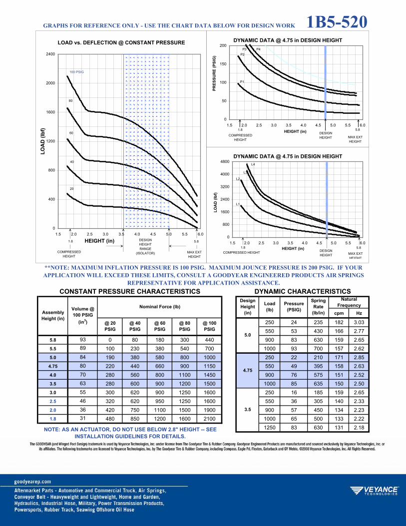
cpm Hz
250 24 235 182 3.03550 53 430 166 2.77
5.8 0 80 180 300 440 900 83 630 159 2.655.5 100 230 380 540 700 1000 93 700 157 2.625.0 190 380 580 800 1000 250 22 210 171 2.854.75 220 440 660 900 1150 550 49 395 158 2.634.0 280 560 800 1100 1450 900 76 575 151 2.523.5 280 600 900 1200 1500 1000 85 635 150 2.503.0 300 620 900 1250 1600 250 16 185 159 2.652.5 320 620 950 1250 1600 550 36 305 140 2.332.0 420 750 1100 1500 1900 900 57 450 134 2.231.8 480 850 1200 1600 2100 1000 65 500 133 2.22
1250 83 630 131 2.18
9389
84
SpringRate
(lb/in)
@ 20 PSIG
4.75
637080
NaturalFrequency
@ 100 PSIG
@ 40 PSIG
@ 60 PSIG
@ 80 PSIG
**NOTE: MAXIMUM INFLATION PRESSURE IS 100 PSIG. MAXIMUM JOUNCE PRESSURE IS 200 PSIG. IF YOUR APPLICATION WILL EXCEED THESE LIMITS, CONSULT A GOODYEAR ENGINEERED PRODUCTS AIR SPRINGS
REPRESENTATIVE FOR APPLICATION ASSISTANCE.CONSTANT PRESSURE CHARACTERISTICS DYNAMIC CHARACTERISTICS
AssemblyHeight (in)
Nominal Force (lb)DesignHeight
(in)
Load(lb)
5.0
Volume @ 100 PSIG
(in3)
Pressure(PSIG)
3.5
463631
55
NOTE: AS AN ACTUATOR, DO NOT USE BELOW 2.8" HEIGHT -- SEE INSTALLATION GUIDELINES FOR DETAILS.
LOAD vs. DEFLECTION @ CONSTANT PRESSURE
0
400
800
1200
1600
2000
2400
1.5 2.0 2.5 3.0 3.5 4.0 4.5 5.0 5.5 6.0
HEIGHT (in)
LOA
D (l
bf)
DESIGNHEIGHTRANGE
(ISOLATOR)COMPRESSEDHEIGHT
20
40
60
80
100 PSIG
MAX EXT HEIGHT
1.8 5.8
DYNAMIC DATA @ 4.75 in DESIGN HEIGHT
0
50
100
150
200
1.5 2.0 2.5 3.0 3.5 4.0 4.5 5.0 5.5 6.0HEIGHT (in)
PRES
SUR
E (P
SIG
)
COMPRESSEDHEIGHT
MAX EXT HEIGHT
DESIGNHEIGHT
P1
P2P3 P4
1.8 5.8
DYNAMIC DATA @ 4.75 in DESIGN HEIGHT
0
800
1600
2400
3200
4000
4800
1.5 2.0 2.5 3.0 3.5 4.0 4.5 5.0 5.5 6.0HEIGHT (in)
LOA
D (l
bf)
COMPRESSED HEIGHT MAX EXT HEIGHT
DESIGNHEIGHT
L2
L3
L4
1.8 5.8
L1
GRAPHS FOR REFERENCE ONLY - USE THE CHART DATA BELOW FOR DESIGN WORK 1B5-520
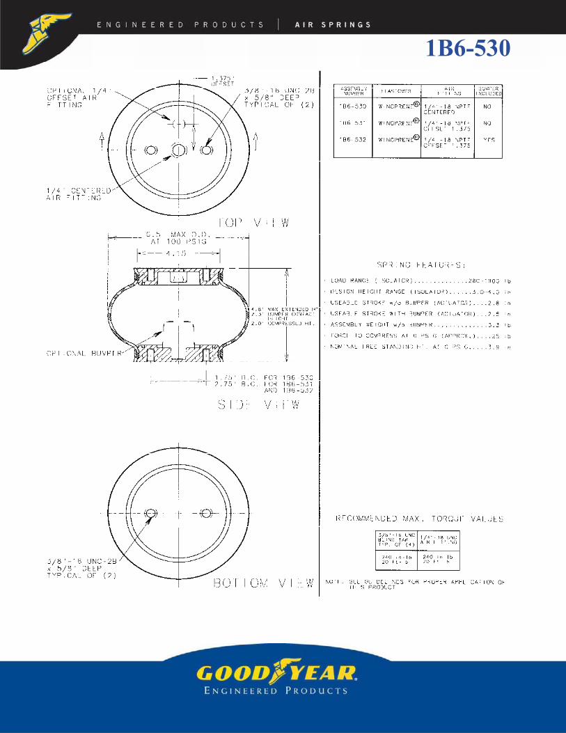
1B6-530

cpm Hz
200 21 375 206 3.43450 37 525 185 3.08
4.8 60 230 440 620 850 750 57 730 173 2.884.5 160 380 640 850 1150 1050 78 940 166 2.774.0 280 580 850 1200 1500 1300 96 1115 163 2.723.5 360 700 1050 1400 1700 200 16 300 190 3.173.0 400 750 1150 1500 1900 450 31 445 169 2.822.5 400 800 1200 1600 2000 750 48 640 164 2.732.0 420 800 1200 1600 2000 1050 67 840 156 2.60
1300 83 1020 155 2.58200 15 325 192 3.20450 28 465 173 2.88750 44 645 164 2.73
1050 61 860 158 2.631300 76 1005 154 2.57
33
5242
62
Volume @ 100 PSIG
(in3)
858071
**NOTE: MAXIMUM INFLATION PRESSURE IS 100 PSIG. MAXIMUM JOUNCE PRESSURE IS 200 PSIG. IF YOUR APPLICATION WILL EXCEED THESE LIMITS, CONSULT A GOODYEAR ENGINEERED PRODUCTS AIR SPRINGS
REPRESENTATIVE FOR APPLICATION ASSISTANCE.CONSTANT PRESSURE CHARACTERISTICS DYNAMIC CHARACTERISTICS
AssemblyHeight (in)
Nominal Force (lb)DesignHeight
(in)
Load(lb)
Pressure(PSIG)
SpringRate
(lb/in)
@ 20 PSIG
3.0
NaturalFrequency
@ 100 PSIG
4.0
@ 40 PSIG
@ 60 PSIG
@ 80 PSIG
3.5
LOAD vs. DEFLECTION @ CONSTANT PRESSURE
0
400
800
1200
1600
2000
2400
2.0 2.2 2.4 2.6 2.8 3.0 3.2 3.4 3.6 3.8 4.0 4.2 4.4 4.6 4.8
HEIGHT (in)
LOA
D (l
bf)
DESIGNHEIGHTRANGE
(ISOLATOR)COMPRESSEDHEIGHT
20
40
60
80
100 PSIG
MAX EXT HEIGHT
DYNAMIC DATA @ 3.5 in DESIGN HEIGHT
0
50
100
150
200
2.0 2.2 2.4 2.6 2.8 3.0 3.2 3.4 3.6 3.8 4.0 4.2 4.4 4.6 4.8HEIGHT (in)
PRES
SUR
E (P
SIG
)
COMPRESSEDHEIGHT
MAX EXT HEIGHT
DESIGNHEIGHT
P1
P2
P3
P4
P5
3.5
DYNAMIC DATA @ 3.5 in DESIGN HEIGHT
0
600
1200
1800
2400
3000
3600
4200
4800
2.0 2.2 2.4 2.6 2.8 3.0 3.2 3.4 3.6 3.8 4.0 4.2 4.4 4.6 4.8HEIGHT (in)
LOA
D (l
bf)
COMPRESSEDHEIGHT
MAX EXT HEIGHT
DESIGNHEIGHT
L1
L2
L3
L4
L5
3.5
GRAPHS FOR REFERENCE ONLY - USE THE CHART DATA BELOW FOR DESIGN WORK 1B6-530

1B6-535

cpm Hz
500 35 365 160 2.671000 65 595 145 2.42
7.1 10 140 300 500 750 1250 79 695 140 2.336.0 250 520 800 1150 1500 1500 94 805 138 2.305.5 320 700 1000 1350 1700 500 25 270 138 2.305.0 380 750 1100 1500 1900 1000 50 470 129 2.154.5 380 800 1200 1600 2100 1250 63 565 127 2.124.0 420 850 1250 1700 2100 1500 75 650 124 2.073.5 420 850 1300 1700 2200 2000 99 820 120 2.003.0 440 850 1300 1700 2200 500 22 270 138 2.302.5 540 1000 1450 2000 2500 1000 45 440 125 2.082.0 750 1250 1800 2300 3000 1250 56 520 121 2.02
1500 68 600 119 1.982000 90 750 116 1.93
6558
9686
76
107
Volume @ 100 PSIG
(in3)
153137
117
4.0
**NOTE: MAXIMUM INFLATION PRESSURE IS 100 PSIG. MAXIMUM JOUNCE PRESSURE IS 200 PSIG. IF YOUR APPLICATION WILL EXCEED THESE LIMITS, CONSULT A GOODYEAR ENGINEERED PRODUCTS AIR SPRINGS
REPRESENTATIVE FOR APPLICATION ASSISTANCE.CONSTANT PRESSURE CHARACTERISTICS DYNAMIC CHARACTERISTICS
AssemblyHeight (in)
Nominal Force (lb)DesignHeight
(in)
Load(lb)
Pressure(PSIG)
SpringRate
(lb/in)
NaturalFrequency
@ 100 PSIG
6.0
5.0
@ 40 PSIG
@ 60 PSIG
@ 80 PSIG
128
@ 20 PSIG
LOAD vs. DEFLECTION @ CONSTANT PRESSURE
0
400
800
1200
1600
2000
2400
2800
3200
2.0 2.5 3.0 3.5 4.0 4.5 5.0 5.5 6.0 6.5 7.0
HEIGHT (in)
LOA
D (l
bf)
DESIGNHEIGHTRANGE
(ISOLATOR)COMPRESSED
HEIGHT
20
40
60
80
100 PSIG
MAX EXT HEIGHT
7.1
DYNAMIC DATA @ 5.0 in DESIGN HEIGHT
0
50
100
150
200
2.0 2.5 3.0 3.5 4.0 4.5 5.0 5.5 6.0 6.5 7.0HEIGHT (in)
PRES
SUR
E (P
SIG
)
COMPRESSEDHEIGHT
MAX EXT HEIGHT
DESIGNHEIGHT
P1
P2
P3 P4 P5
7.1
DYNAMIC DATA @ 5.0 in DESIGN HEIGHT
0
1000
2000
3000
4000
5000
6000
2.0 2.5 3.0 3.5 4.0 4.5 5.0 5.5 6.0 6.5 7.0HEIGHT (in)
LOA
D (l
bf)
COMPRESSEDHEIGHT
MAX EXT HEIGHT
DESIGNHEIGHT
L1
L2
L3 L4
L5
7.1
GRAPHS FOR REFERENCE ONLY - USE THE CHART DATA BELOW FOR DESIGN WORK 1B6-535

1B7-540

cpm Hz
650 42 535 171 2.851000 63 775 165 2.75
5.2 100 200 350 600 850 1400 86 1025 160 2.675.0 140 340 580 850 1100 650 34 485 163 2.724.5 260 560 850 1250 1600 1000 52 685 155 2.584.0 340 700 1100 1500 1900 1400 72 910 151 2.523.5 400 800 1250 1700 2200 1800 91 1120 148 2.473.0 440 900 1400 1900 2400 650 31 470 159 2.652.5 480 950 1450 2000 2500 1000 46 650 152 2.532.0 500 1000 1500 2000 2600 1400 64 865 148 2.47
1800 81 1060 144 2.40
@ 40 PSIG
@ 60 PSIG
@ 80 PSIG 4.5
4.0
3.5
NaturalFrequency
@ 100 PSIG
**NOTE: MAXIMUM INFLATION PRESSURE IS 100 PSIG. MAXIMUM JOUNCE PRESSURE IS 200 PSIG. IF YOUR APPLICATION WILL EXCEED THESE LIMITS, CONSULT A GOODYEAR ENGINEERED PRODUCTS AIR SPRINGS
REPRESENTATIVE FOR APPLICATION ASSISTANCE.CONSTANT PRESSURE CHARACTERISTICS DYNAMIC CHARACTERISTICS
AssemblyHeight (in)
Nominal Force (lb)DesignHeight
(in)
Load(lb)
Pressure(PSIG)
SpringRate
(lb/in)
@ 20 PSIG
109
Volume @ 100 PSIG
(in3)
119
112117
32
90
7855
LOAD vs. DEFLECTION @ CONSTANT PRESSURE
0
400
800
1200
1600
2000
2400
2800
2.0 2.5 3.0 3.5 4.0 4.5 5.0
HEIGHT (in)
LOA
D (l
bf)
DESIGNHEIGHTRANGE
(ISOLATOR)COMPRESSED
HEIGHT
20
40
60
80
100 PSIG
MAX EXT HEIGHT
5.2
DYNAMIC DATA @ 4.0 in DESIGN HEIGHT
0
50
100
150
200
2.0 2.5 3.0 3.5 4.0 4.5 5.0HEIGHT (in)
PRES
SUR
E (P
SIG
)
COMPRESSEDHEIGHT
MAX EXT HEIGHT
DESIGNHEIGHT
P1
P2
P3
P4
5.2
DYNAMIC DATA @ 4.0 in DESIGN HEIGHT
0
1000
2000
3000
4000
5000
6000
2.0 2.5 3.0 3.5 4.0 4.5 5.0HEIGHT (in)
LOA
D (l
bf)
COMPRESSEDHEIGHT
MAX EXT HEIGHT
DESIGNHEIGHT
L1
L2
L3
L4
5.2
GRAPHS FOR REFERENCE ONLY - USE THE CHART DATA BELOW FOR DESIGN WORK 1B7-540

1B8-550

cpm Hz
850 43 740 176 2.931350 66 1100 170 2.83
5.3 100 300 550 800 1100 1850 88 1420 165 2.755.0 240 540 900 1000 1600 850 38 675 168 2.80
4.75 320 680 1100 1500 2000 1350 60 1010 162 2.704.5 380 800 1300 1700 2200 1850 80 1315 158 2.63
3.75 540 1100 1700 2300 2900 2400 100 1610 155 2.583.5 580 1150 1900 2500 3100 850 30 620 160 2.673.0 620 1250 2000 2700 3300 1350 47 895 153 2.552.5 640 1300 2100 2800 3500 1850 63 1170 149 2.482.0 660 1350 2100 2800 3600 2400 80 1425 146 2.43
@ 40 PSIG
@ 60 PSIG
@ 80 PSIG
NaturalFrequency
@ 100 PSIG 4.75
**NOTE: MAXIMUM INFLATION PRESSURE IS 100 PSIG. MAXIMUM JOUNCE PRESSURE IS 200 PSIG. IF YOUR APPLICATION WILL EXCEED THESE LIMITS, CONSULT A GOODYEAR ENGINEERED PRODUCTS AIR SPRINGS
REPRESENTATIVE FOR APPLICATION ASSISTANCE.CONSTANT PRESSURE CHARACTERISTICS DYNAMIC CHARACTERISTICS
AssemblyHeight (in)
Nominal Force (lb)DesignHeight
(in)
Load(lb)
Pressure(PSIG)
SpringRate
(lb/in)
@ 20 PSIG
Volume @ 100 PSIG
(in3)
145
138
128133
4.5
3.75
60
1049078
110
LOAD vs. DEFLECTION @ CONSTANT PRESSURE
0
600
1200
1800
2400
3000
3600
2.0 2.5 3.0 3.5 4.0 4.5 5.0 5.5HEIGHT (in)
LOA
D (l
bf)
DESIGNHEIGHTRANGE
(ISOLATOR)COMPRESSED
HEIGHT
20
40
60
80
100 PSIG
MAX EXT HEIGHT
5.3
DYNAMIC DATA @ 4.5 in DESIGN HEIGHT
0
50
100
150
200
2.0 2.5 3.0 3.5 4.0 4.5 5.0 5.5HEIGHT (in)
PRES
SUR
E (P
SIG
)
COMPRESSEDHEIGHT
MAX EXT HEIGHT
DESIGNHEIGHT
P1
P2 P3 P4
5.3
DYNAMIC DATA @ 4.5 in DESIGN HEIGHT
0
1000
2000
3000
4000
5000
6000
7000
8000
9000
2.0 2.5 3.0 3.5 4.0 4.5 5.0 5.5HEIGHT (in)
LOA
D (l
bf)
COMPRESSEDHEIGHT
MAX EXT HEIGHT
DESIGNHEIGHT
L1
L2
L3
L4
5.3
GRAPHS FOR REFERENCE ONLY - USE THE CHART DATA BELOW FOR DESIGN WORK 1B8-550

1B8-560

cpm Hz
500 32 480 184 3.071000 56 725 160 2.67
6.7 80 450 750 1200 1600 1500 78 965 151 2.526.5 180 540 950 1450 1900 2000 98 1165 142 2.375.5 420 900 1450 2000 2700 500 22 355 158 2.634.5 560 1150 1800 2400 3100 1000 40 545 138 2.304.0 600 1200 1850 2600 3300 1500 58 725 130 2.173.5 640 1300 1900 2700 3400 2000 76 905 126 2.103.0 680 1350 2000 2700 3500 2500 91 1045 122 2.032.5 700 1350 2100 3000 3900 500 15 322 150 2.502.0 800 1650 2500 3500 4500 1000 31 520 134 2.23
1500 46 670 125 2.082000 61 860 122 2.032500 76 1005 119 1.98
104111
162146129
178
Volume @ 100 PSIG
(in3)
239
208
235
**NOTE: MAXIMUM INFLATION PRESSURE IS 100 PSIG. MAXIMUM JOUNCE PRESSURE IS 200 PSIG. IF YOUR APPLICATION WILL EXCEED THESE LIMITS, CONSULT A GOODYEAR ENGINEERED PRODUCTS AIR SPRINGS
REPRESENTATIVE FOR APPLICATION ASSISTANCE.CONSTANT PRESSURE CHARACTERISTICS DYNAMIC CHARACTERISTICS
AssemblyHeight (in)
Nominal Force (lb)DesignHeight
(in)
Load(lb)
Pressure(PSIG)
SpringRate
(lb/in)
@ 20 PSIG
NaturalFrequency
@ 100 PSIG
6.5
5.5
4.0
@ 40 PSIG
@ 60 PSIG
@ 80 PSIG
LOAD vs. DEFLECTION @ CONSTANT PRESSURE
0
600
1200
1800
2400
3000
3600
4200
4800
2.0 2.5 3.0 3.5 4.0 4.5 5.0 5.5 6.0 6.5
HEIGHT (in)
LOA
D (l
bf)
DESIGNHEIGHTRANGE
(ISOLATOR)COMPRESSED
HEIGHT
20
40
60
80
100 PSIG
MAX EXT HEIGHT
6.7
DYNAMIC DATA @ 5.5 in DESIGN HEIGHT
0
40
80
120
160
200
2.0 2.5 3.0 3.5 4.0 4.5 5.0 5.5 6.0 6.5HEIGHT (in)
PRES
SUR
E (P
SIG
)
COMPRESSEDHEIGHT
MAX EXT HEIGHT
DESIGNHEIGHT
P1
P2
P3 P4
6.7
P5
1.8
DYNAMIC DATA @ 5.5 in DESIGN HEIGHT
0
2000
4000
6000
8000
10000
2.0 2.5 3.0 3.5 4.0 4.5 5.0 5.5 6.0 6.5HEIGHT (in)
LOA
D (l
bf)
COMPRESSEDHEIGHT
MAX EXT HEIGHT
DESIGNHEIGHT
L1
L2
L3 L4
6.7
L5
GRAPHS FOR REFERENCE ONLY - USE THE CHART DATA BELOW FOR DESIGN WORK 1B8-560

1B9-202

cpm Hz
500 15 355 158 2.631000 31 695 157 2.62
5.9 280 560 850 1200 1500 1500 46 990 153 2.555.5 480 950 1450 1900 2500 2200 67 1405 150 2.505.2 580 1140 1700 2300 2900 2800 83 1740 148 2.475.0 640 1250 1900 2600 3200 500 14 360 159 2.65
4.75 700 1400 2100 2800 3600 1000 28 640 150 2.504.5 750 1500 2300 3100 3900 1500 41 940 149 2.484.0 850 1700 2600 3500 4400 2200 61 1310 145 2.423.5 900 1900 2900 3900 4900 2800 77 1650 144 2.403.0 1000 2000 3100 4200 5200 500 13 360 158 2.632.5 1050 2100 3200 4400 5500 1000 25 630 150 2.502.3 1100 2200 3300 4500 5600 1500 38 900 146 2.43
2200 55 1255 143 2.382800 70 1570 141 2.35
126
260
@ 40 PSIG
@ 60 PSIG
244
Volume @ 100 PSIG
(in3)
283270
253
162
@ 80 PSIG
4.75
4.5
NaturalFrequency
@ 100 PSIG
5.0
**NOTE: MAXIMUM INFLATION PRESSURE IS 100 PSIG. MAXIMUM JOUNCE PRESSURE IS 200 PSIG. IF YOUR APPLICATION WILL EXCEED THESE LIMITS, CONSULT A GOODYEAR ENGINEERED PRODUCTS AIR SPRINGS
REPRESENTATIVE FOR APPLICATION ASSISTANCE.
CONSTANT PRESSURE CHARACTERISTICS DYNAMIC CHARACTERISTICS
AssemblyHeight (in)
Nominal Force (lb)DesignHeight
(in)
Load(lb)
Pressure(PSIG)
SpringRate
(lb/in)
@ 20 PSIG
136
233211187
LOAD vs. DEFLECTION @ CONSTANT PRESSURE
0
500
1000
1500
2000
2500
3000
3500
4000
4500
5000
5500
6000
2.0 2.5 3.0 3.5 4.0 4.5 5.0 5.5 6.0
HEIGHT (in)
LOA
D (l
bf)
DESIGNHEIGHTRANGE
(ISOLATOR)COMPRESSED
HEIGHT
20
40
60
80
100 PSIG
MAX EXT HEIGHT
2.3 5.9
DYNAMIC DATA @ 4.75 in DESIGN HEIGHT
0
50
100
150
200
2.25 2.75 3.25 3.75 4.25 4.75 5.25 5.75HEIGHT (in)
PRES
SUR
E (P
SIG
)
COMPRESSEDHEIGHT
5.9 MAX EXT HEIGHT
ISOLATOR
P1
P2
P3
P4
P5
2.35.2 MAX
EXT HEIGHTACTUATOR
DESIGNHEIGHT
DYNAMIC DATA @ 4.75 in DESIGN HEIGHT
0
2000
4000
6000
8000
10000
12000
2.25 2.75 3.25 3.75 4.25 4.75 5.25 5.75HEIGHT (in)
LOA
D (l
bf)
COMPRESSEDHEIGHT
5.9 MAX EXT HEIGHT
L1
L2
L3
L4
L5
2.35.2 MAXEXT HEIGHTACTUATOR
5.2 MAX EXT HEIGHTACTUATOR
DESIGNHEIGHT
GRAPHS FOR REFERENCE ONLY - USE THE CHART DATA BELOW FOR DESIGN WORK 1B9-202

1B12-313

cpm Hz
2000 28 1040 135 2.253000 42 1415 129 2.15
7.2 440 1050 1800 2700 3600 4000 55 1810 127 2.126.5 800 1800 2800 3900 5100 5000 69 2175 124 2.076.0 1050 2200 3100 4600 6000 6500 89 2725 121 2.025.6 1150 2450 3650 5050 6550 2000 25 1225 147 2.455.5 1200 2500 3800 5200 6700 3000 37 1640 139 2.325.0 1350 2800 4200 5700 7300 4.0 4000 49 2055 135 2.254.5 1450 3000 4500 6100 7800 5000 61 2475 132 2.204.0 1500 3100 4800 6500 8200 6500 79 3070 129 2.153.5 1600 3300 5000 6800 8500 2000 23 1570 167 2.783.0 1700 3400 5100 7000 8800 3000 34 2120 158 2.632.3 1700 3500 5300 7100 9100 3.0 4000 46 2600 151 2.52
5000 57 3425 148 2.476500 74 3895 145 2.42
311263190
489445400354
Pressure(PSIG)
SpringRate
(lb/in)
@ 20 PSIG
Volume @ 100 PSIG
(in3)
NaturalFrequency
@ 100 PSIG
5.0
**NOTE: MAXIMUM INFLATION PRESSURE IS 100 PSIG. MAXIMUM JOUNCE PRESSURE IS 200 PSIG. IF YOUR APPLICATION WILL EXCEED THESE LIMITS, CONSULT A GOODYEAR ENGINEERED PRODUCTS AIR SPRINGS
REPRESENTATIVE FOR APPLICATION ASSISTANCE.CONSTANT PRESSURE CHARACTERISTICS DYNAMIC CHARACTERISTICS
AssemblyHeight (in)
Nominal Force (lb)DesignHeight
(in)
Load(lb)
497
@ 40 PSIG
@ 60 PSIG
@ 80 PSIG
618569531
LOAD vs. DEFLECTION @ CONSTANT PRESSURE
0
1000
2000
3000
4000
5000
6000
7000
8000
9000
10000
2.0 2.5 3.0 3.5 4.0 4.5 5.0 5.5 6.0 6.5 7.0 7.5
HEIGHT (in)
LOA
D (l
bf)
DESIGNHEIGHTRANGE
(ISOLATOR)COMPRESSED
HEIGHT
20
40
60
80
100 PSIG
7.2MAX EXT HEIGHT
ISOLATOR
2.3 5.6MAX EXTHEIGHT
ACTUATOR
DYNAMIC DATA @ 4.0 in DESIGN HEIGHT
0
50
100
150
200
2.0 2.5 3.0 3.5 4.0 4.5 5.0 5.5 6.0 6.5 7.0 7.5HEIGHT (in)
PRES
SUR
E (P
SIG
)
COMPRESSEDHEIGHT
7.2MAX EXT HEIGHT
ISOLATORDESIGNHEIGHT
P1
P2
P3
P4
P5
2.3
DYNAMIC DATA @ 4.0 in DESIGN HEIGHT
0
2000
4000
6000
8000
10000
12000
14000
16000
2.0 2.5 3.0 3.5 4.0 4.5 5.0 5.5 6.0 6.5 7.0 7.5HEIGHT (in)
LOA
D (l
bf)
COMPRESSEDHEIGHT
7.2 MAX EXT HEIGHT
ISOLATORDESIGNHEIGHT
L1
L2
L3
L4
L5
2.35.6
MAX EXT HEIGHTACTUATOR
5.6MAX. EXT.
HEIGHTACTUATOR
GRAPHS FOR REFERENCE ONLY - USE THE CHART DATA BELOW FOR DESIGN WORK 1B12-313
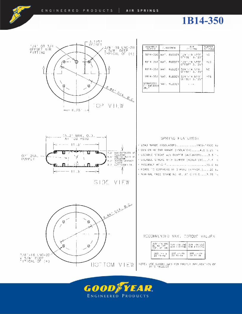
1B14-350

cpm Hz
2500 26 1420 141 2.354500 46 2280 133 2.22
7.2 680 1600 2600 3700 4900 6500 65 3065 129 2.156.5 1200 2600 4000 5500 7100 8500 85 3895 127 2.126.0 1500 3100 4900 6600 8400 2500 22 1625 152 2.535.6 1700 3500 5400 7300 9300 4500 39 2505 140 2.335.25 1900 3800 5900 7900 10000 6500 56 3340 135 2.255.0 2000 4000 6200 8300 10500 8500 73 4215 132 2.204.25 2200 4600 6900 9200 11700 10500 90 5035 130 2.174.0 2300 4700 7100 9500 11900 2500 21 1755 157 2.623.5 2400 4900 7400 9900 12500 4500 38 2635 144 2.403.0 2500 5100 7700 10300 12900 6500 55 3495 138 2.302.3 2600 5200 7900 10500 13300 8500 71 4390 135 2.25
10500 88 5260 133 2.22
247335
663
590496
464399
@ 40 PSIG
@ 60 PSIG
@ 80 PSIG
NaturalFrequency
@ 100 PSIG
5.25
SpringRate
(lb/in)
4.25
4.0
**NOTE: MAXIMUM INFLATION PRESSURE IS 100 PSIG. MAXIMUM JOUNCE PRESSURE IS 200 PSIG. IF YOUR APPLICATION WILL EXCEED THESE LIMITS, CONSULT A GOODYEAR ENGINEERED PRODUCTS AIR SPRINGS
REPRESENTATIVE FOR APPLICATION ASSISTANCE.CONSTANT PRESSURE CHARACTERISTICS DYNAMIC CHARACTERISTICS
AssemblyHeight (in)
Nominal Force (lb)DesignHeight
(in)
Load(lb)
Pressure(PSIG)
709
621
@ 20 PSIG
Volume @ 100 PSIG
(in3)
824762
LOAD vs. DEFLECTION @ CONSTANT PRESSURE
0
2000
4000
6000
8000
10000
12000
14000
2.0 2.5 3.0 3.5 4.0 4.5 5.0 5.5 6.0 6.5 7.0 7.5
HEIGHT (in)
LOA
D (l
bf)
DESIGNHEIGHTRANGE
(ISOLATOR)COMPRESSED
HEIGHT
20
40
60
80
100 PSIG
7.2MAX EXT HEIGHT
ISOLATOR
2.35.6
MAX EXTHEIGHT
ACTUATOR
DYNAMIC DATA @ 4.25 in DESIGN HEIGHT
0
50
100
150
200
2.0 2.5 3.0 3.5 4.0 4.5 5.0 5.5 6.0 6.5 7.0 7.5HEIGHT (in)
PRES
SUR
E (P
SIG
)
COMPRESSEDHEIGHT
7.2MAX EXT HEIGHT
ISOLATORDESIGNHEIGHT
P1
P2
P3
P4 P5
2.35.6
MAX EXTHEIGHT
ACTUATOR
DYNAMIC DATA @ 4.25 in DESIGN HEIGHT
0
5000
10000
15000
20000
25000
30000
2.0 2.5 3.0 3.5 4.0 4.5 5.0 5.5 6.0 6.5 7.0 7.5HEIGHT (in)
LOA
D (l
bf)
COMPRESSEDHEIGHT
7.2 MAX EXT HEIGHT
ISOLATORDESIGNHEIGHT
L1
L2
L3
L4
L5
2.3 5.6 MAXEXT HEIGHTACTUATOR
GRAPHS FOR REFERENCE ONLY - USE THE CHART DATA BELOW FOR DESIGN WORK 1B14-350

1B15-375

cpm Hz
4000 33 1770 125 2.086000 50 2470 121 2.02
7.9 380 1450 2400 3700 4900 8000 66 3160 118 1.977.0 1250 2700 4300 6000 7900 10000 82 3885 117 1.956.5 1700 3500 5400 7500 9600 12000 97 4560 116 1.936.0 2000 4100 6300 8500 10900 4000 30 1930 130 2.175.8 2000 4200 6500 8900 11300 6000 45 2655 125 2.085.4 2200 4600 7100 9600 12000 8000 60 2340 122 2.034.6 2500 5200 7900 10700 13400 10000 74 4025 119 1.984.4 2600 5300 8100 10900 13700 12000 89 4720 118 1.973.5 2800 5700 8700 11700 14700 4000 30 2035 134 2.233.0 2900 5900 9000 12100 15100 6000 44 2710 126 2.102.3 3100 6500 9600 13400 16700 8000 59 3445 123 2.05
10000 76 4170 121 2.0212000 87 4890 120 2.00
363
@ 40 PSIG
@ 60 PSIG
@ 80 PSIG
Volume @ 100 PSIG
(in3)
11301035970
679
545
4.6
4.4
NaturalFrequency
@ 100 PSIG
5.4
**NOTE: MAXIMUM INFLATION PRESSURE IS 100 PSIG. MAXIMUM JOUNCE PRESSURE IS 200 PSIG. IF YOUR APPLICATION WILL EXCEED THESE LIMITS, CONSULT A GOODYEAR ENGINEERED PRODUCTS AIR SPRINGS
REPRESENTATIVE FOR APPLICATION ASSISTANCE.CONSTANT PRESSURE CHARACTERISTICS DYNAMIC CHARACTERISTICS
AssemblyHeight (in)
Nominal Force (lb)DesignHeight
(in)
Load(lb)
Pressure(PSIG)
SpringRate
(lb/in)
@ 20 PSIG
469
904879822712
LOAD vs. DEFLECTION @ CONSTANT PRESSURE
0
1000
2000
3000
4000
5000
6000
7000
8000
9000
10000
11000
12000
13000
14000
15000
16000
17000
18000
2.2 2.6 3.0 3.4 3.8 4.2 4.6 5.0 5.4 5.8 6.2 6.6 7.0 7.4 7.8
HEIGHT (in)
LOA
D (l
bf)
DESIGNHEIGHTRANGE
(ISOLATOR)
COMPRESSEDHEIGHT
20
40
60
80
100 PSIG
7.9MAX EXT HEIGHT
ISOLATOR
DYNAMIC DATA @ 4.6 in DESIGN HEIGHT
0
40
80
120
160
200
2.2 2.6 3.0 3.4 3.8 4.2 4.6 5.0 5.4 5.8 6.2 6.6 7.0 7.4 7.8
HEIGHT (in)
PRES
SUR
E (P
SIG
)
COMPRESSEDHEIGHT
7.9 MAXEXT HEIGHTISOLATOR
DESIGNHEIGHT
P1
P2
P3
P4 P5
MAX EXTHEIGHT
ACTUATO
2.3
DYNAMIC DATA @ 4.6 in DESIGN HEIGHT
0
5000
10000
15000
20000
25000
30000
35000
2.2 2.6 3.0 3.4 3.8 4.2 4.6 5.0 5.4 5.8 6.2 6.6 7.0 7.4 7.8HEIGHT (in)
LOA
D (l
bf)
COMPRESSEDHEIGHT
7.9 MAX EXT HEIGHTISOLATOR
DESIGNHEIGHT
`L1
L2
L3
L4
L5
2.3 MAX EXTHEIGHT
ACTUATION
MAX EXTHEIGHT
ACTUATOR
2.3
GRAPHS FOR REFERENCE ONLY - USE THE CHART DATA BELOW FOR DESIGN WORK 1B15-375

2B6-530

cpm Hz
250 24 245 188 3.13500 44 370 160 2.67
7.7 -- 90 220 380 580 1000 80 600 146 2.437.0 110 300 520 750 1000 250 15 185 162 2.706.5 180 420 680 1000 1300 500 30 290 143 2.386.0 250 520 800 1100 1500 1000 60 525 136 2.275.5 300 620 900 1300 1600 1500 89 750 134 2.235.0 340 680 1000 1400 1800 250 13 205 170 2.834.5 360 700 1100 1500 2000 500 26 350 157 2.624.0 380 750 1200 1700 2150 1000 52 620 147 2.453.5 440 900 1350 1900 2400 1500 77 865 143 2.382.8 750 1200 1700 2300 2800 2000 100 1120 141 2.35
@ 40 PSIG
@ 60 PSIG
@ 80 PSIG
108
@ 20 PSIG
NaturalFrequency
@ 100 PSIG 6.5
5.5
4.5
**NOTE: MAXIMUM INFLATION PRESSURE IS 100 PSIG. MAXIMUM JOUNCE PRESSURE IS 200 PSIG. IF YOUR APPLICATION WILL EXCEED THESE LIMITS, CONSULT A GOODYEAR ENGINEERED PRODUCTS AIR SPRINGS
REPRESENTATIVE FOR APPLICATION ASSISTANCE.CONSTANT PRESSURE CHARACTERISTICS DYNAMIC CHARACTERISTICS
AssemblyHeight (in)
Nominal Force (lb)DesignHeight
(in)
Load(lb)
Pressure(PSIG)
SpringRate
(lb/in)
91
Volume @ 100 PSIG
(in3)
125
115
100
5136
827262
LOAD vs. DEFLECTION @ CONSTANT PRESSURE
0
400
800
1200
1600
2000
2400
2800
3200
2.5 3.0 3.5 4.0 4.5 5.0 5.5 6.0 6.5 7.0 7.5
HEIGHT (in)
LOA
D (l
bf)
DESIGNHEIGHTRANGE
(ISOLATOR)COMPRESSEDHEIGHT
20
40
60
80
100 PSIG
MAX EXT HEIGHT
2.8 7.7
DYNAMIC DATA @ 5.5 in DESIGN HEIGHT
0
50
100
150
200
2.5 3.0 3.5 4.0 4.5 5.0 5.5 6.0 6.5 7.0 7.5HEIGHT (in)
PRES
SUR
E (P
SIG
)
COMPRESSEDHEIGHT
MAX EXT HEIGHT
DESIGNHEIGHT
P1
P2
P3 P4
2.8 7.7
DYNAMIC DATA @ 5.5 in DESIGN HEIGHT
0
1000
2000
3000
4000
5000
6000
2.5 3.0 3.5 4.0 4.5 5.0 5.5 6.0 6.5 7.0 7.5HEIGHT (in)
LOA
D (l
bf)
COMPRESSEDHEIGHT
MAX EXT HEIGHT
DESIGNHEIGHT
L1
L2
L3
L4
2.8 7.7
GRAPHS FOR REFERENCE ONLY - USE THE CHART DATA BELOW FOR DESIGN WORK 2B6-530

2B6-535

cpm Hz
500 32 245 131 2.18750 47 335 126 2.10
9.1 0 80 200 380 560 1000 63 440 125 2.088.5 90 260 460 680 900 1250 78 530 123 2.058.0 170 400 630 900 1150 1500 94 645 122 2.037.5 240 500 750 1100 1400 500 26 250 132 2.207.0 300 580 900 1250 1500 750 40 345 128 2.136.0 380 750 1100 1500 1900 1000 53 440 124 2.075.0 440 850 1300 1800 2200 1250 65 530 122 2.034.5 520 1000 1450 2000 2500 1500 77 625 121 2.023.5 680 1250 1800 2400 3000 500 23 360 159 2.652.8 750 1500 2100 2700 3300 750 34 475 149 2.48
1000 45 595 145 2.421250 57 705 141 2.351500 68 845 140 2.33
@ 40 PSIG
@ 60 PSIG
@ 80 PSIG
155
6.0
5.0
NaturalFrequency
@ 100 PSIG
7.0
**NOTE: MAXIMUM INFLATION PRESSURE IS 100 PSIG. MAXIMUM JOUNCE PRESSURE IS 200 PSIG. IF YOUR APPLICATION WILL EXCEED THESE LIMITS, CONSULT A GOODYEAR ENGINEERED PRODUCTS AIR SPRINGS
REPRESENTATIVE FOR APPLICATION ASSISTANCE.CONSTANT PRESSURE CHARACTERISTICS DYNAMIC CHARACTERISTICS
AssemblyHeight (in)
Nominal Force (lb)DesignHeight
(in)
Load(lb)
Pressure(PSIG)
SpringRate
(lb/in)
@ 20 PSIG
138
Volume @ 100 PSIG
(in3)
169162
147
5938
1199785
LOAD vs. DEFLECTION @ CONSTANT PRESSURE
0
400
800
1200
1600
2000
2400
2800
3200
3600
2.5 3.0 3.5 4.0 4.5 5.0 5.5 6.0 6.5 7.0 7.5 8.0 8.5 9.0 9.5HEIGHT (in)
LOA
D (l
bf)
DESIGNHEIGHTRANGE
(ISOLATOR)COMPRESSED
HEIGHT
20
40
60
80
100 PSIG
MAX EXT HEIGHT
2.8 9.1
DYNAMIC DATA @ 6.0 in DESIGN HEIGHT
0
50
100
150
200
2.5 3.0 3.5 4.0 4.5 5.0 5.5 6.0 6.5 7.0 7.5 8.0 8.5 9.0 9.5HEIGHT (in)
PRES
SUR
E (P
SIG
)
COMPRESSEDHEIGHT
MAX EXT HEIGHT
DESIGNHEIGHT
P1
P2 P3 P4P5
2.8 9.1
DYNAMIC DATA @ 6.0 in DESIGN HEIGHT
0
1000
2000
3000
4000
5000
6000
7000
2.5 3.0 3.5 4.0 4.5 5.0 5.5 6.0 6.5 7.0 7.5 8.0 8.5 9.0 9.5HEIGHT (in)
LOA
D (l
bf)
COMPRESSEDHEIGHT
MAX EXT HEIGHT
DESIGNHEIGHT
L1
L2 L3 L4L5
2.8 9.1
GRAPHS FOR REFERENCE ONLY - USE THE CHART DATA BELOW FOR DESIGN WORK 2B6-535

2B7-540

cpm Hz
730 48 450 147 2.451150 72 655 142 2.37
9.0 0 110 280 540 800 1500 92 800 137 2.288.5 120 320 640 900 1250 730 31 335 126 2.108.0 230 500 800 1200 1600 1150 49 480 122 2.037.0 380 800 1200 1700 2100 1500 63 595 118 1.976.5 460 900 1350 1800 2300 1950 81 730 115 1.926.0 500 950 1450 2000 2500 730 30 325 125 2.085.0 540 1100 1600 2200 2800 1150 46 475 121 2.024.0 560 1150 1700 2400 3000 1500 59 575 117 1.953.0 580 1200 1800 2400 3100 1950 76 715 114 1.902.5 620 1200 1800 2500 3200
@ 40 PSIG
@ 60 PSIG
@ 80 PSIG 8.0
6.5
6.0
NaturalFrequency
@ 100 PSIG
**NOTE: MAXIMUM INFLATION PRESSURE IS 100 PSIG. MAXIMUM JOUNCE PRESSURE IS 200 PSIG. IF YOUR APPLICATION WILL EXCEED THESE LIMITS, CONSULT A GOODYEAR ENGINEERED PRODUCTS AIR SPRINGS
REPRESENTATIVE FOR APPLICATION ASSISTANCE.CONSTANT PRESSURE CHARACTERISTICS DYNAMIC CHARACTERISTICS
AssemblyHeight (in)
Nominal Force (lb)DesignHeight
(in)
Load(lb)
Pressure(PSIG)
SpringRate
(lb/in)
@ 20 PSIG
182
Volume @ 100 PSIG
(in3)
232
222
195214
7459
151136105
LOAD vs. DEFLECTION @ CONSTANT PRESSURE
0
400
800
1200
1600
2000
2400
2800
3200
2.5 3.0 3.5 4.0 4.5 5.0 5.5 6.0 6.5 7.0 7.5 8.0 8.5 9.0HEIGHT (in)
LOA
D (l
bf)
DESIGNHEIGHTRANGE
(ISOLATOR)COMPRESSEDHEIGHT
20
40
60
80
100 PSIG
MAX EXT HEIGHT
DYNAMIC DATA @ 6.5 in DESIGN HEIGHT
0
50
100
150
200
2.5 3.0 3.5 4.0 4.5 5.0 5.5 6.0 6.5 7.0 7.5 8.0 8.5 9.0HEIGHT (in)
PRES
SUR
E (P
SIG
)
COMPRESSEDHEIGHT
MAX EXT HEIGHT
DESIGNHEIGHT
P1
P2 P3 P4
DYNAMIC DATA @ 6.5 in DESIGN HEIGHT
0
1000
2000
3000
4000
5000
6000
7000
2.5 3.0 3.5 4.0 4.5 5.0 5.5 6.0 6.5 7.0 7.5 8.0 8.5 9.0HEIGHT (in)
LOA
D (l
bf)
COMPRESSED HEIGHT MAX EXT HEIGHT
DESIGNHEIGHT
L1
L2
L3 L4
GRAPHS FOR REFERENCE ONLY - USE THE CHART DATA BELOW FOR DESIGN WORK 2B7-540

2B8-550

cpm Hz
500 22 230 128 2.131000 44 400 120 2.00
10.1 30 180 450 700 1000 1500 65 560 115 1.929.0 300 600 1000 1350 1800 2000 87 710 112 1.878.0 440 850 1300 1800 2300 500 20 220 125 2.087.5 500 950 1450 2000 2500 1000 41 385 117 1.957.0 540 1050 1600 2100 2700 1500 60 535 112 1.876.0 600 1200 1800 2400 3100 2000 79 680 110 1.835.0 750 1400 2100 2900 3600 2500 99 820 108 1.804.0 950 1700 2500 3400 4300 500 19 220 125 2.083.5 1000 1900 2800 3700 4600 1000 38 380 116 1.932.9 1200 2100 3100 4100 5000 1500 57 530 112 1.87
2000 74 675 109 1.822500 92 820 108 1.80
9975
190156
121
221
Volume @ 100 PSIG
(in3)
295274
235249
**NOTE: MAXIMUM INFLATION PRESSURE IS 100 PSIG. MAXIMUM JOUNCE PRESSURE IS 200 PSIG. IF YOUR APPLICATION WILL EXCEED THESE LIMITS, CONSULT A GOODYEAR ENGINEERED PRODUCTS AIR SPRINGS
REPRESENTATIVE FOR APPLICATION ASSISTANCE.CONSTANT PRESSURE CHARACTERISTICS DYNAMIC CHARACTERISTICS
AssemblyHeight (in)
Nominal Force (lb)DesignHeight
(in)
Load(lb)
Pressure(PSIG)
SpringRate
(lb/in)
@ 20 PSIG
NaturalFrequency
@ 100 PSIG
8.0
7.5
7.0
@ 40 PSIG
@ 60 PSIG
@ 80 PSIG
LOAD vs. DEFLECTION @ CONSTANT PRESSURE
0
600
1200
1800
2400
3000
3600
4200
4800
5400
2.5 3.5 4.5 5.5 6.5 7.5 8.5 9.5 10.5HEIGHT (in)
LOA
D (l
bf)
DESIGNHEIGHTRANGE
(ISOLATOR)COMPRESSED
HEIGHT
20
40
60
80
100 PSIG
MAX EXT HEIGHT
2.9 10.1
DYNAMIC DATA @ 7.5 in DESIGN HEIGHT
0
50
100
150
200
2.5 3.5 4.5 5.5 6.5 7.5 8.5 9.5 10.5HEIGHT (in)
PRES
SUR
E (P
SIG
)
COMPRESSEDHEIGHT
MAX EXT HEIGHT
DESIGNHEIGHT
P1
P2 P3 P4
2.9
P5
10.1
DYNAMIC DATA @ 7.5 in DESIGN HEIGHT
0
2000
4000
6000
8000
10000
12000
14000
2.5 3.5 4.5 5.5 6.5 7.5 8.5 9.5 10.5HEIGHT (in)
LOA
D (l
bf)
COMPRESSEDHEIGHT
MAX EXT HEIGHT
DESIGNHEIGHT
L1
L2 L3 L4
2.9
L5
10.1
GRAPHS FOR REFERENCE ONLY - USE THE CHART DATA BELOW FOR DESIGN WORK 2B8-550

2B9-200

cpm Hz
500 24 320 150 2.501000 45 480 130 2.17
10.8 20 200 400 700 1100 1500 64 705 129 2.1510.0 250 620 1000 1500 1900 2250 90 980 124 2.079.5 340 800 1300 1800 2300 500 18 255 133 2.228.5 540 1150 1700 2400 3100 1000 34 400 119 1.987.5 660 1400 2100 2900 3700 1500 50 570 116 1.936.5 750 1600 2400 3300 4200 2250 72 755 110 1.835.5 850 1700 2600 3600 4500 3000 94 1010 109 1.824.5 900 1900 2800 3900 4900 500 15 230 127 2.123.5 950 2000 3100 4300 5400 1000 29 395 117 1.953.2 1000 2100 3300 4500 5700 1500 43 540 113 1.88
2250 62 750 109 1.823000 81 950 106 1.77
169155
321274
223
363
Volume @ 100 PSIG
(in3)
475442
399429
**NOTE: MAXIMUM INFLATION PRESSURE IS 100 PSIG. MAXIMUM JOUNCE PRESSURE IS 200 PSIG. IF YOUR APPLICATION WILL EXCEED THESE LIMITS, CONSULT A GOODYEAR ENGINEERED PRODUCTS AIR SPRINGS
REPRESENTATIVE FOR APPLICATION ASSISTANCE.CONSTANT PRESSURE CHARACTERISTICS DYNAMIC CHARACTERISTICS
AssemblyHeight (in)
Nominal Force (lb)DesignHeight
(in)
Load(lb)
Pressure(PSIG)
SpringRate
(lb/in)
@ 20 PSIG
@ 40 PSIG
@ 60 PSIG
@ 80 PSIG
9.5
8.5
7.5
Natural Frequency
@ 100 PSIG
LOAD vs. DEFLECTION @ CONSTANT PRESSURE
0
500
1000
1500
2000
2500
3000
3500
4000
4500
5000
5500
6000
3.0 4.0 5.0 6.0 7.0 8.0 9.0 10.0 11.0
HEIGHT (in)
LOA
D (l
bf)
DESIGNHEIGHTRANGE
(ISOLATOR)COMPRESSEDHEIGHT
20
40
60
80
100 PSIG
10.8 MAX EXT HEIGHTISOLATOR
3.2
9.5 MAXEXT HEIGHTACTUATOR
DYNAMIC DATA @ 8.5 in DESIGN HEIGHT
0
50
100
150
200
3.0 4.0 5.0 6.0 7.0 8.0 9.0 10.0 11.0HEIGHT (in)
PRES
SUR
E (P
SIG
)
COMPRESSEDHEIGHT
10.8 MAX EXT HEIGHT
P1
P2
P3 P4 P5
3.2
DYNAMIC DATA @ 8.5 in DESIGN HEIGHT
0
2000
4000
6000
8000
10000
12000
14000
3.0 4.0 5.0 6.0 7.0 8.0 9.0 10.0 11.0
HEIGHT (in)
LOA
D (l
bf)
COMPRESSEDHEIGHT
10.8 MAX EXT HEIGHT
ISOLATOR
L1
L2
L3
L4 L5
3.2
DESIGNHEIGHT
9.5 MAXEXT HEIGHT
DESIGNHEIGHT
9.5 MAXEXT HEIGHTACTUATOR
GRAPHS FOR REFERENCE ONLY - USE THE CHART DATA BELOW FOR DESIGN WORK 2B9-200

2B9-250

cpm Hz
750 26 285 115 1.921500 51 515 110 1.83
12.2 120 440 800 1150 1500 2300 76 695 103 1.7211.5 280 700 1100 1500 2000 3100 99 930 103 1.7210.7 410 900 1400 1900 2500 750 22 255 109 1.8210.0 540 1150 1700 2300 3000 1500 43 405 98 1.639.0 640 1350 2000 2800 3500 2300 66 670 101 1.688.0 750 1500 2300 3100 3800 3100 87 885 100 1.677.5 800 1600 2400 3200 4000 750 18 185 93 1.556.5 850 1700 2600 3500 4400 1500 38 450 103 1.725.5 900 1800 2800 3800 4800 2300 58 635 99 1.654.5 1000 2000 3000 4100 5100 3100 79 855 98 1.633.5 1250 2400 3600 4700 6000 3900 98 1025 96 1.60
273221
449418382363
**NOTE: MAXIMUM INFLATION PRESSURE IS 100 PSIG. MAXIMUM JOUNCE PRESSURE IS 200 PSIG. IF YOUR APPLICATION WILL EXCEED THESE LIMITS, CONSULT A GOODYEAR ENGINEERED PRODUCTS AIR SPRINGS
REPRESENTATIVE FOR APPLICATION ASSISTANCE.CONSTANT PRESSURE CHARACTERISTICS DYNAMIC CHARACTERISTICS
AssemblyHeight (in)
Nominal Force (lb)DesignHeight
(in)
Load(lb)
Pressure(PSIG)
SpringRate
(lb/in)
@ 20 PSIG
NaturalFrequency
@ 100 PSIG
10.0
9.0
163
467
8.0
@ 40 PSIG
@ 60 PSIG
@ 80 PSIG
Volume @ 100 PSIG
(in3)
500487
320
LOAD vs. DEFLECTION @ CONSTANT PRESSURE
0
500
1000
1500
2000
2500
3000
3500
4000
4500
5000
5500
6000
6500
3.5 4.5 5.5 6.5 7.5 8.5 9.5 10.5 11.5 12.5
HEIGHT (in)
LOA
D (l
bf)
DESIGNHEIGHTRANGE
(ISOLATOR)COMPRESSED
HEIGHT
20
40
60
80
100 PSIG
12.2 MAX EXT HEIGHT
ISOLATOR
DYNAMIC DATA @ 9.0 in DESIGN HEIGHT
0
50
100
150
200
3.5 4.5 5.5 6.5 7.5 8.5 9.5 10.5 11.5 12.5
HEIGHT (in)
PRES
SUR
E (P
SIG
)
COMPRESSEDHEIGHT
12.2 MAX EXT HEIGHTISOLATORDESIGN
HEIGHT
`
P1
P2P3 P4
10.7MAX EXTHEIGHT
ACTUATOR
DYNAMIC DATA @ 9.0 in DESIGN HEIGHT
0
2000
4000
6000
8000
10000
12000
14000
3.5 4.5 5.5 6.5 7.5 8.5 9.5 10.5 11.5 12.5HEIGHT (in)
LOA
D (l
bf)
COMPRESSEDHEIGHT
12.2 MAX EXT HEIGHTISOLATOR
DESIGNHEIGHT
L1
L2
L3 L4
10.7 MAX EXT EIGHTACTUATOR
10.7MAX EXTHEIGHT
ACTUATOR
GRAPHS FOR REFERENCE ONLY - USE THE CHART DATA BELOW FOR DESIGN WORK 2B9-250

2B12-425

cpm Hz
1000 20 420 123 2.05
3000 59 1095 114 1.90
11.1 240 660 1200 1900 2700 5000 95 1720 110 1.83
10.5 580 1200 2000 2900 3800 1000 17 395 118 1.97
9.5 900 1900 2900 4000 5200 3000 49 965 106 1.77
9.0 1000 2200 3300 4500 5800 5000 79 1490 103 1.72
8.5 1150 2300 3600 4900 6300 6000 95 1760 102 1.70
7.5 1350 2700 4100 5600 7200 1000 15 415 121 2.02
6.5 1500 3100 4500 6200 7900 3000 43 940 106 1.77
5.5 1600 3200 4900 6700 8400 5000 72 1480 102 1.70
4.5 1700 3400 5200 7100 9000 6000 85 1735 101 1.68
3.5 1700 3500 5500 7400 9400 7000 99 1985 100 1.67
3.4 1600 3400 5500 7400 9400277
285
7.5
@ 40 PSIG
@ 60 PSIG
@ 80 PSIG
Volume @ 100 PSIG
(in3)
821
779
751
NaturalFrequency
@ 100 PSIG 9.5
8.5
**NOTE: MAXIMUM INFLATION PRESSURE IS 100 PSIG. MAXIMUM JOUNCE PRESSURE IS 200 PSIG. IF YOUR APPLICATION WILL EXCEED THESE LIMITS, CONSULT A GOODYEAR ENGINEERED PRODUCTS AIR SPRINGS
REPRESENTATIVE FOR APPLICATION ASSISTANCE.CONSTANT PRESSURE CHARACTERISTICS DYNAMIC CHARACTERISTICS
AssemblyHeight (in)
Nominal Force (lb)DesignHeight
(in)
Load(lb)
Pressure(PSIG)
SpringRate
(lb/in)
@ 20 PSIG
463
377
717
684
612
536
LOAD vs. DEFLECTION @ CONSTANT PRESSURE
0
1000
2000
3000
4000
5000
6000
7000
8000
9000
10000
3.5 4.5 5.5 6.5 7.5 8.5 9.5 10.5 11.5
HEIGHT (in)
LOA
D (l
bf)
DESIGNHEIGHTRANGE
(ISOLATOR)
3.4COMPRESSED
HEIGHT
20
40
60
80
100 PSIG
11.1MAX EXT HEIGHT
ISOLATOR
9.5MAX EXTHEIGHT
ACTUATOR
DYNAMIC DATA @ 8.5 in DESIGN HEIGHT
0
50
100
150
200
3.5 4.5 5.5 6.5 7.5 8.5 9.5 10.5 11.5HEIGHT (in)
PRES
SUR
E (P
SIG
)
3.4COMPRESSED
HEIGHT
11.1 MAX EXT HEIGHT
ISOLATOR
DESIGNHEIGHT
P1
P2
P3 P4
DYNAMIC DATA @ 8.5 in DESIGN HEIGHT
0
2000
4000
6000
8000
10000
12000
14000
16000
18000
20000
3.5 4.5 5.5 6.5 7.5 8.5 9.5 10.5 11.5HEIGHT (in)
LOA
D (l
bf)
3.4COMPRESSED
HEIGHT
11.1 MAX EXT HEIGHTISOLATOR
DESIGNHEIGHT
L1
L2
L3 L4
MAX EXTHEIGHTACTUATOR
MAX EXTHEIGHTACTUATOR
GRAPHS FOR REFERENCE ONLY - USE THE CHART DATA BELOW FOR DESIGN WORK 2B12-425

2B12-440

2B12-440
cpm Hz
1000 15 335 108 1.802000 30 550 98 1.63
14.4 70 460 1150 1700 2600 3000 44 720 92 1.5313.0 580 1300 2200 3200 4300 5000 71 1115 89 1.4812.7 660 1400 2400 3400 4500 7000 99 1510 87 1.4512.0 850 1800 2900 4000 5200 1000 14 355 112 1.8711.0 1050 2200 3400 4700 6100 2000 27 560 99 1.659.5 1300 2600 4100 5500 7100 3000 41 780 96 1.608.5 1450 2900 4400 6000 7600 5000 66 1180 91 1.527.5 1500 3100 4700 6400 8100 7000 93 1560 88 1.476.0 1700 3400 5200 6900 8800 1000 13 410 120 2.005.0 1800 3600 5500 7400 9400 2000 26 645 106 1.774.3 1800 3800 5800 7800 10000 3000 38 880 102 1.703.6 1980 4100 6300 8400 10000 5000 63 1310 96 1.603.5 2000 4200 6400 8600 11000 7000 87 1755 94 1.57
**NOTE: MAXIMUM INFLATION PRESSURE IS 100 PSIG. MAXIMUM JOUNCE PRESSURE IS 200 PSIG. IF YOUR APPLICATION WILL EXCEED THESE LIMITS, CONSULT A GOODYEAR ENGINEERED PRODUCTS
REPRESENTATIVE FOR APPLICATION ASSISTANCE.
CONSTANT PRESSURE CHARACTERISTICS DYNAMIC CHARACTERISTICS
AssemblyHeight (in)
Nominal Force (lb)DesignHeight
(in)
Load(lb)
Pressure(PSIG)
SpringRate
(lb/in)
@ 20 PSIG
@ 80 PSIG
8.5
7.5
NaturalFrequency
@ 100 PSIG
9.5
10941077
1032961
@ 40 PSIG
@ 60 PSIG
Volume @ 100 PSIG
(in3)
1169
844761
320
393329
456
676
545
LOAD vs. DEFLECTION @ CONSTANT PRESSURE
0
1000
2000
3000
4000
5000
6000
7000
8000
9000
10000
11000
12000
3.5 4.5 5.5 6.5 7.5 8.5 9.5 10.5 11.5 12.5 13.5 14.5HEIGHT (in)
LOA
D (l
bf)
DESIGNHEIGHTRANGE
(ISOLATOR)
3.6COMPRESSEDHT PEDESTAL
MOUNT
20
40
60
80
100 PSIG
14.4 MAX EXT HEIGHT
ISOLATOR
4.3COMPRESSED
HT PLATE MOUNT12.7 MAX EXTHEIGHTACTUATOR
DYNAMIC DATA @ 8.5 in DESIGN HEIGHT
0
50
100
150
200
3.5 4.5 5.5 6.5 7.5 8.5 9.5 10.5 11.5 12.5 13.5 14.5HEIGHT (in)
PRES
SUR
E (P
SIG
)
14.4 MAX EXT HEIGHT
ISOLATORDESIGNHEIGHT
`P1
P2
P3
P4 P5
3.6 COMPRESSEDHT PEDESTAL
MOUNT12.7 MAX
EXT HEIGTACTUATOR
DYNAMIC DATA @ 8.5 in DESIGN HEIGHT
0
4000
8000
12000
16000
20000
24000
28000
3.5 4.5 5.5 6.5 7.5 8.5 9.5 10.5 11.5 12.5 13.5 14.5HEIGHT (in)
LOA
D (l
bf)
3.6 COMPRESSED HT PEDESTAL
MOUNT
14.4 MAX EXT HEIGHT
ISOLATOR
DESIGNHEIGHT
L1
L2
L3
L4
L5
4.3 COMPRESSEDHT. PLATE MOUNT
12.7 MAXEXT HEIGHTACTUATOR
4.3COMPRESSED
HT PLATE MOUNT
GRAPHS FOR REFERENCE ONLY - USE THE CHART DATA BELOW FOR DESIGN WORK 2B12-440

2B14-354

cpm Hz
2000 24 810 119 1.984000 48 1435 112 1.87
11.3 480 1200 2000 2700 3400 6000 70 2015 109 1.8210.5 1100 2300 3500 5600 6200 8000 93 2615 107 1.789.7 1400 3000 4600 6500 7900 2000 20 730 114 1.909.5 1500 3200 4900 6600 8400 4000 41 1305 107 1.789.0 1700 3500 5400 7300 9200 6000 61 1830 104 1.738.5 1900 3900 5900 7900 10000 8000 80 2355 102 1.707.5 2200 4400 6600 8900 11100 10000 99 2860 100 1.676.5 2400 4800 7200 9700 12200 2000 18 805 119 1.985.5 2500 5100 7600 10300 12900 4000 36 1370 109 1.824.5 2600 5300 8000 10700 13200 6000 54 1860 105 1.753.7 2650 5350 8100 10900 13700 8000 72 2395 103 1.723.5 2700 5400 8200 11000 13900 10000 90 2925 102 1.70389
756631509413
1119
1046994879
1100
@ 40 PSIG
@ 60 PSIG
@ 80 PSIG
NaturalFrequency
@ 100 PSIG
9.5
SpringRate
(lb/in)
8.5
7.5
**NOTE: MAXIMUM INFLATION PRESSURE IS 100 PSIG. MAXIMUM JOUNCE PRESSURE IS 200 PSIG. IF YOUR APPLICATION WILL EXCEED THESE LIMITS, CONSULT A GOODYEAR ENGINEERED PRODUCTS AIR SPRINGS
REPRESENTATIVE FOR APPLICATION ASSISTANCE.CONSTANT PRESSURE CHARACTERISTICS DYNAMIC CHARACTERISTICS
AssemblyHeight (in)
Nominal Force (lb)DesignHeight
(in)
Load(lb)
Pressure(PSIG)
@ 20 PSIG
Volume @ 100 PSIG
(in3)
12441189
LOAD vs. DEFLECTION @ CONSTANT PRESSURE
0
1000
2000
3000
4000
5000
6000
7000
8000
9000
10000
11000
12000
13000
14000
15000
3.5 4.5 5.5 6.5 7.5 8.5 9.5 10.5 11.5
HEIGHT (in)
LOA
D (l
bf)
DESIGNHEIGHTRANGE
(ISOLATOR)
3.7COMPRESSED
HEIGHT
20
40
60
80
100 PSIG
MAX EXT HEIGHT
ISOLATOR
11.39.7MAX EXTHEIGHTACTUATIOR
DYNAMIC DATA @ 8.5 in DESIGN HEIGHT
0
50
100
150
200
3.5 4.5 5.5 6.5 7.5 8.5 9.5 10.5 11.5HEIGHT (in)
PRES
SUR
E (P
SIG
)
COMPRESSEDHEIGHT
11.3 MAXEXT HEIGHTISOLATOR
DESIGNHEIGHT
`
P1
P2
P3 P4 P5
3.7
9.7 MAXEXT HEIGHTACTUATOR
DYNAMIC DATA @ 8.5 in DESIGN HEIGHT
0
5000
10000
15000
20000
25000
30000
35000
3.5 4.5 5.5 6.5 7.5 8.5 9.5 10.5 11.5HEIGHT (in)
LOA
D (l
bf)
3.7COMPRESSED
HEIGHT
11.3 MAX EXT HEIGHT
ISOLATOR
DESIGNHEIGHT
L1
L2
L3 L4 L5
3.7
9.7 MAXEXT HEIGHTACTUATOR
GRAPHS FOR REFERENCE ONLY - USE THE CHART DATA BELOW FOR DESIGN WORK 2B14-354

2B14-362
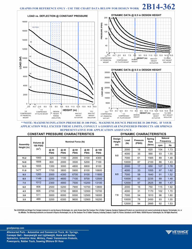
cpm Hz
2000 18 620 104 1.734000 35 990 93 1.55
15.2 320 1100 2000 3100 4300 7000 61 1565 89 1.4814.0 800 2000 3500 5200 7100 10000 87 2100 86 1.4312.5 1350 3000 4800 6800 9100 2000 17 650 107 1.7811.0 1700 3800 5900 8100 10600 4000 33 1055 97 1.629.5 2000 4300 6700 9100 11800 7000 58 1640 91 1.528.5 2200 4600 7100 9700 12500 10000 82 2235 89 1.487.5 2300 4900 7500 10200 13100 12000 97 2625 88 1.476.0 2500 5200 7900 10700 13800 2000 16 750 115 1.924.5 2700 5700 8800 12000 15700 4000 31 1170 102 1.703.8 3000 6000 9300 12500 16000 7000 54 1810 96 1.603.5 3200 6300 9600 12900 16200 10000 78 2450 93 1.55
12000 94 2895 92 1.53
@ 40 PSIG
@ 60 PSIG
@ 80 PSIG
NaturalFrequency
@ 100 PSIG
9.5
**NOTE: MAXIMUM INFLATION PRESSURE IS 100 PSIG. MAXIMUM JOUNCE PRESSURE IS 200 PSIG. IF YOUR APPLICATION WILL EXCEED THESE LIMITS, CONSULT A GOODYEAR ENGINEERED PRODUCTS AIR SPRINGS
REPRESENTATIVE FOR APPLICATION ASSISTANCE.CONSTANT PRESSURE CHARACTERISTICS DYNAMIC CHARACTERISTICS
AssemblyHeight (in)
Nominal Force (lb)DesignHeight
(in)
Load(lb)
Pressure(PSIG)
SpringRate
(lb/in)
@ 20 PSIG
Volume @ 100 PSIG
(in3)
19001806
1655
8.5
7.5
806605511
1477128311491012
469
LOAD vs. DEFLECTION @ CONSTANT PRESSURE
0
2000
4000
6000
8000
10000
12000
14000
16000
18000
3.5 4.5 5.5 6.5 7.5 8.5 9.5 10.5 11.5 12.5 13.5 14.5 15.5
HEIGHT (in)
LOA
D (l
bf)
DESIGNHEIGHTRANGE
(ISOLATOR)
3.8COMPRESSEDHT PEDESTAL
MOUNT
20
40
60
80
100 PSIG
15.2MAX EXT HEIGHT
ISOLATOR
4.5COMPRESSED
HT PLATE MOUNT MAX EXTHEIGHT
ACTUATOR
DYNAMIC DATA @ 8.5 in DESIGN HEIGHT
0
40
80
120
160
200
3.5 4.5 5.5 6.5 7.5 8.5 9.5 10.5 11.5 12.5 13.5 14.5 15.5HEIGHT (in)
PRES
SUR
E (P
SIG
)
3.8COMPRESSEDHT PEDESTAL
MOUNT
15.2 MAX EXT HEIGHTISOLATOR
DESIGNHEIGHT
`
P1
P2
P3
P4 P5
4.5COMPRESSED
HT. PLATE MOUNT
DYNAMIC DATA @ 8.5 in DESIGN HEIGHT
0
5000
10000
15000
20000
25000
30000
35000
3.5 4.5 5.5 6.5 7.5 8.5 9.5 10.5 11.5 12.5 13.5 14.5 15.5HEIGHT (in)
LOA
D (l
bf)
3.8COMPRESSEDHT. PEDESTAL
MOUNT
15.2 MAX EXT HEIGHT
ISOLATORDESIGNHEIGHT
L1
L2
L3
L4
L5
MAX EXT HEIGHT
ACTUATOR
4.5COMPRESSED
HT. PLATE MOUNT
MAX EXTHEIGHT
ACTUATOR
GRAPHS FOR REFERENCE ONLY - USE THE CHART DATA BELOW FOR DESIGN WORK 2B14-362

2B15-375

cpm Hz
2000 20 660 108 1.804000 39 1140 100 1.67
12.8 300 1000 1500 2000 2500 6000 58 1610 97 1.6211.5 1300 2600 4000 5200 6500 8000 78 2085 95 1.5810.5 1700 3400 5200 7000 8800 2000 18 680 109 1.8210.3 1800 3500 5400 7200 9000 4000 35 1150 100 1.679.5 2000 4000 6100 8200 10300 6000 53 1605 97 1.628.5 2300 4500 6800 9100 11400 8000 70 2050 95 1.587.5 2500 4900 7300 9900 12300 2000 16 765 116 1.936.5 2600 5100 7800 10500 13200 4000 33 1230 104 1.735.5 2700 5300 8200 11100 13700 6000 49 1690 100 1.674.5 2800 5500 8500 11400 14200 8000 65 2155 97 1.623.7 2900 5800 9000 12100 15100 12000 97 3090 95 1.583.5 3000 6000 9200 12400 15500
@ 40 PSIG
@ 60 PSIG
@ 80 PSIG
NaturalFrequency
@ 100 PSIG
9.5
SpringRate
(lb/in)
8.5
7.5
**NOTE: MAXIMUM INFLATION PRESSURE IS 100 PSIG. MAXIMUM JOUNCE PRESSURE IS 200 PSIG. IF YOUR APPLICATION WILL EXCEED THESE LIMITS, CONSULT A GOODYEAR ENGINEERED PRODUCTS AIR SPRINGS
REPRESENTATIVE FOR APPLICATION ASSISTANCE.CONSTANT PRESSURE CHARACTERISTICS DYNAMIC CHARACTERISTICS
AssemblyHeight (in)
Nominal Force (lb)DesignHeight
(in)
Load(lb)
Pressure(PSIG)
1373
@ 20 PSIG
Volume @ 100 PSIG
(in3)
16151472
1348
11351008875
475500605
1259
740
LOAD vs. DEFLECTION @ CONSTANT PRESSURE
0
1000
2000
3000
4000
5000
6000
7000
8000
9000
10000
11000
12000
13000
14000
15000
16000
3.5 4.5 5.5 6.5 7.5 8.5 9.5 10.5 11.5 12.5
HEIGHT (in)
LOA
D (l
bf)
DESIGNHEIGHTRANGE
(ISOLATOR)
3.7COMPRESSED
HEIGHT
20
40
60
80
100 PSIG
12.8 MAX EXT HEIGHT
ISOLATOR
10.3 MAXEXT HEIGHTACTUATOR
DYNAMIC DATA @ 8.5 in DESIGN HEIGHT
0
40
80
120
160
200
3.5 4.5 5.5 6.5 7.5 8.5 9.5 10.5 11.5 12.5
HEIGHT (in)
PRES
SUR
E (P
SIG
)
3.7COMPRESSED
HEIGHT
12.8 MAX EXT HEIGHT
ISOLATORDESIGNHEIGHT
`P1
P2
P3 P4
10.3 MAXEXT HEIGHTACTUATOR
DYNAMIC DATA @ 8.5 in DESIGN HEIGHT
0
5000
10000
15000
20000
25000
30000
3.5 4.5 5.5 6.5 7.5 8.5 9.5 10.5 11.5 12.5
HEIGHT (in)
LOA
D (l
bf)
3.7COMPRESSED
HEIGHT
12.8 MAX EXT HEIGHTISOLATOR
DESIGNHEIGHT
`L1
L2
L3 L4
10.3 MAXEXT HEIGHTACTUATOR
GRAPHS FOR REFERENCE ONLY - USE THE CHART DATA BELOW FOR DESIGN WORK 2B15-375

2B19-8433

cpm Hz
10.0 3500 22 1285 114 1.906000 36 1990 108 1.80
12.0 1150 3100 5400 8000 10700 10000 58 2975 103 1.7211.0 2400 5200 8000 11400 14700 15000 85 4155 99 1.6510.0 3200 6600 10000 13800 17700 8.5 3500 18 1250 112 1.878.5 4100 8200 12500 16800 21200 6000 30 1860 105 1.757.0 4600 9300 14100 18800 23700 10000 49 2790 99 1.656.0 4900 9800 14800 19800 24900 15000 72 3905 96 1.605.0 5100 10400 15700 21000 26500 20000 96 5030 94 1.574.0 5300 10800 16300 21800 27400 7.0 3500 16 1480 122 2.033.25 5400 10900 16400 21900 27500 6000 27 2095 111 1.85
10000 44 3105 105 1.7515000 66 4290 101 1.6820000 87 5495 99 1.65
1293876
248324532188
1681
Volume @ 100 PSIG
(in3)
28022662
2036
**NOTE: MAXIMUM INFLATION PRESSURE IS 100 PSIG. MAXIMUM JOUNCE PRESSURE IS 200 PSIG. IF YOUR APPLICATION WILL EXCEED THESE LIMITS, CONSULT A GOODYEAR ENGINEERED PRODUCTS AIR SPRINGS
REPRESENTATIVE FOR APPLICATION ASSISTANCE.CONSTANT PRESSURE CHARACTERISTICS DYNAMIC CHARACTERISTICS
AssemblyHeight (in)
Nominal Force (lb)DesignHeight
(in)
Load(lb)
Pressure(PSIG)
SpringRate
(lb/in)
@ 20 PSIG
NaturalFrequency
@ 100 PSIG
@ 40 PSIG
@ 60 PSIG
@ 80 PSIG
LOAD vs. DEFLECTION @ CONSTANT PRESSURE
0
5000
10000
15000
20000
25000
30000
3.0 4.0 5.0 6.0 7.0 8.0 9.0 10.0 11.0 12.0
HEIGHT (in)
LOA
D (l
bf)
DESIGNHEIGHTRANGE
(ISOLATOR)COMPRESSED
HEIGHT
20
40
60
80
100 PSIG
MAX EXT HEIGHT
3.25
DYNAMIC DATA @ 8.5 in DESIGN HEIGHT
0
40
80
120
160
200
3.0 4.0 5.0 6.0 7.0 8.0 9.0 10.0 11.0 12.0
HEIGHT (in)
PRES
SUR
E (P
SIG
)
COMPRESSEDHEIGHT
MAX EXT HEIGHT
DESIGNHEIGHT
P1
P2 P3
P4 P5
3.25
DYNAMIC DATA @ 8.5 in DESIGN HEIGHT
0
10000
20000
30000
40000
50000
3.0 4.0 5.0 6.0 7.0 8.0 9.0 10.0 11.0 12.0
HEIGHT (in)
LOA
D (l
bf)
COMPRESSEDHEIGHT
MAX EXT HEIGHT
DESIGNHEIGHT
L1
L2L3
L4 L5
3.25
GRAPHS FOR REFERENCE ONLY - USE THE CHART DATA BELOW FOR DESIGN WORK 2B19-8433

2B22-8539

cpm Hz
6000 23 1880 105 1.7510000 38 2740 98 1.63
12.5 1700 4500 7700 11100 14800 15000 56 3790 95 1.5811.5 3300 7000 11000 15400 19800 20000 74 4815 92 1.5310.5 4300 8800 13500 18500 23500 25000 92 5795 90 1.509.0 5200 10700 16200 21900 27700 6000 21 2025 109 1.828.0 5700 11600 17600 23700 29800 10000 36 2885 101 1.687.0 6200 12400 18800 25200 31700 15000 53 4025 97 1.626.0 6500 13100 19800 26600 33600 20000 70 5065 95 1.585.0 6900 13800 20800 28000 35200 25000 87 6210 94 1.574.0 7000 14100 21300 28500 35800 6000 21 2235 115 1.923.25 6800 13800 21000 28100 35300 10000 34 3230 107 1.78
15000 51 4395 102 1.7020000 67 5590 99 1.6525000 83 6780 98 1.63
@ 40 PSIG
@ 60 PSIG
@ 80 PSIG
8.0
7.0
NaturalFrequency
@ 100 PSIG
9.0
**NOTE: MAXIMUM INFLATION PRESSURE IS 100 PSIG. MAXIMUM JOUNCE PRESSURE IS 200 PSIG. IF YOUR APPLICATION WILL EXCEED THESE LIMITS, CONSULT A GOODYEAR ENGINEERED PRODUCTS AIR SPRINGS
REPRESENTATIVE FOR APPLICATION ASSISTANCE.CONSTANT PRESSURE CHARACTERISTICS DYNAMIC CHARACTERISTICS
AssemblyHeight (in)
Nominal Force (lb)DesignHeight
(in)
Load(lb)
Pressure(PSIG)
SpringRate
(lb/in)
@ 20 PSIG
Volume @ 100 PSIG
(in3)
33173095
1601
840716
2877
250924701919
1215
LOAD vs. DEFLECTION @ CONSTANT PRESSURE
0
5000
10000
15000
20000
25000
30000
35000
40000
3.0 4.0 5.0 6.0 7.0 8.0 9.0 10.0 11.0 12.0
HEIGHT (in)
LOA
D (l
bf)
DESIGNHEIGHTRANGE
(ISOLATOR)COMPRESSED
HEIGHT
20
40
60
80
100 PSIG
MAX EXT HEIGHT
3.25
DYNAMIC DATA @ 8.0 in DESIGN HEIGHT
0
40
80
120
160
200
3.0 4.0 5.0 6.0 7.0 8.0 9.0 10.0 11.0 12.0
HEIGHT (in)
PRES
SUR
E (P
SIG
)
COMPRESSEDHEIGHT
MAX EXT HEIGHT
DESIGNHEIGHT
P1P2 P3 P4
P5
3.25
DYNAMIC DATA @ 8.0 in DESIGN HEIGHT
0
10000
20000
30000
40000
50000
3.0 4.0 5.0 6.0 7.0 8.0 9.0 10.0 11.0 12.0
HEIGHT (in)
LOA
D (l
bf)
COMPRESSEDHEIGHT
MAX EXT HEIGHT
DESIGNHEIGHT
`
L1 L2 L3L4 L5
3.25
GRAPHS FOR REFERENCE ONLY - USE THE CHART DATA BELOW FOR DESIGN WORK 2B22-8539

3B12-304

cpm Hz
1000 22 275 99 1.652000 41 455 91 1.52
18.0 200 700 1350 2100 2900 3500 69 735 87 1.4517.0 460 1150 1900 2900 3800 5000 98 1010 84 1.4016.0 700 1500 2400 3500 4600 1000 18 280 100 1.6715.4 790 1700 2700 3800 4600 2000 33 435 88 1.4715.0 1159 850 1800 2900 4000 5200 3500 58 655 81 1.3513.0 1033 1150 2300 3600 5000 6400 5000 80 900 80 1.3311.0 890 1350 2700 4100 5600 7100 6000 96 1070 79 1.329.0 1500 2900 4500 6200 8100 1000 15 275 98 1.637.0 1700 3500 5300 7300 9200 2000 29 450 89 1.486.0 1800 3700 5600 7600 9600 3500 51 680 83 1.384.8 1980 3900 5800 7900 10000 5000 71 950 82 1.374.7 2000 3900 5800 7900 10000 6000 85 1110 80 1.33383
390
1183
732568486 11.0
@ 40 PSIG
@ 60 PSIG
@ 80 PSIG
NaturalFrequency
@ 100 PSIG
15.0
13.0
**NOTE: MAXIMUM INFLATION PRESSURE IS 100 PSIG. MAXIMUM JOUNCE PRESSURE IS 200 PSIG. IF YOUR APPLICATION WILL EXCEED THESE LIMITS, CONSULT A GOODYEAR ENGINEERED PRODUCTS AIR SPRINGS
REPRESENTATIVE FOR APPLICATION ASSISTANCE.CONSTANT PRESSURE CHARACTERISTICS DYNAMIC CHARACTERISTICS
AssemblyHeight (in)
Nominal Force (lb)DesignHeight
(in)
Load(lb)
Pressure(PSIG)
SpringRate
(lb/in)
@ 20 PSIG
Volume @ 100 PSIG
(in3)
13021261
1214
LOAD vs. DEFLECTION @ CONSTANT PRESSURE
0
1000
2000
3000
4000
5000
6000
7000
8000
9000
10000
11000
4.5 5.5 6.5 7.5 8.5 9.5 10.5 11.5 12.5 13.5 14.5 15.5 16.5 17.5
HEIGHT (in)
LOA
D (l
bf)
DESIGNHEIGHTRANGE
(ISOLATOR)COMPRESSED
HEIGHT
20
40
60
80
100 PSIG
18.0MAX EXT HEIGHT
ISOLATOR
4.8 15.4MAX EXTHEIGHT
ACTUATOR
DYNAMIC DATA @ 13.0 in DESIGN HEIGHT
0
50
100
150
200
4.5 5.5 6.5 7.5 8.5 9.5 10.5 11.5 12.5 13.5 14.5 15.5 16.5 17.5
HEIGHT (in)
PRES
SUR
E (P
SIG
)
COMPRESSEDHEIGHT
18.0 MAX EXT HEIGHTISOLATOR
DESIGNHEIGHT
P1
P2P3 P4 P5
4.8 15.4 MAX EXT HEIGHT
ACTUATOR
DYNAMIC DATA @ 13.0 in DESIGN HEIGHT
0
4000
8000
12000
16000
20000
24000
4.5 5.5 6.5 7.5 8.5 9.5 10.5 11.5 12.5 13.5 14.5 15.5 16.5 17.5HEIGHT (in)
LOA
D (l
bf)
COMPRESSEDHEIGHT
18.0 MAX EXT HEIGHT
ISOLATOR
DESIGNHEIGHT
L1
L2
L3 L4
L5
4.8 15.4 MAXEXT HEIGHTACTUATOR
GRAPHS FOR REFERENCE ONLY - USE THE CHART DATA BELOW FOR DESIGN WORK 3B12-304

3B12-325

cpm Hz
15.0 2000 34 360 79 1.323500 57 635 80 1.33
19.0 300 800 1500 2200 2900 5000 80 865 78 1.3018.0 550 1300 2100 3000 4000 6000 95 1020 77 1.2817.0 800 1700 2700 3700 4800 2000 29 340 78 1.3016.0 950 2000 3200 4400 5600 3500 50 675 83 1.3815.7 1000 2100 3300 4500 5800 5000 70 895 80 1.3315.0 1100 2300 3600 4900 6300 6000 83 970 76 1.2713.0 1400 2800 4300 5800 7400 7000 96 1135 75 1.2511.0 1550 3200 4900 6600 8400 2000 26 445 88 1.479.0 1850 3700 5600 7600 9600 3500 45 670 82 1.377.0 2050 4100 6300 8400 10600 5000 62 925 81 1.356.0 2100 4250 6500 8700 10900 6000 75 1080 80 1.334.6 2100 4400 6700 9100 11500 7000 86 1235 79 1.324.5 2200 4500 6800 9200 11600429
433560
142013731235
1085892681 11.0
@ 40 PSIG
@ 60 PSIG
@ 80 PSIG
NaturalFrequency
@ 100 PSIG
13.0
**NOTE: MAXIMUM INFLATION PRESSURE IS 100 PSIG. MAXIMUM JOUNCE PRESSURE IS 200 PSIG. IF YOUR APPLICATION WILL EXCEED THESE LIMITS, CONSULT A GOODYEAR ENGINEERED PRODUCTS AIR SPRINGS
REPRESENTATIVE FOR APPLICATION ASSISTANCE.CONSTANT PRESSURE CHARACTERISTICS DYNAMIC CHARACTERISTICS
AssemblyHeight (in)
Nominal Force (lb)DesignHeight
(in)
Load(lb)
Pressure(PSIG)
SpringRate
(lb/in)
@ 20 PSIG
1440
Volume @ 100 PSIG
(in3)
15981550
1504
LOAD vs. DEFLECTION @ CONSTANT PRESSURE
0
1000
2000
3000
4000
5000
6000
7000
8000
9000
10000
11000
12000
4.5 6.0 7.5 9.0 10.5 12.0 13.5 15.0 16.5 18.0
HEIGHT (in)
LOA
D (l
bf)
DESIGNHEIGHTRANGE
(ISOLATOR)COMPRESSED
HEIGHT
20
40
60
80
100 PSIG
19.0MAX EXT HEIGHT
ISOLATOR
15.7MAX EXTHEIGHT
ACTUATOR
DYNAMIC DATA @ 13.0 in DESIGN HEIGHT
0
50
100
150
200
4.5 6.0 7.5 9.0 10.5 12.0 13.5 15.0 16.5 18.0
HEIGHT (in)
PRES
SUR
E (P
SIG
)
COMPRESSEDHEIGHT
19 MAX EXT HEIGHT
ISOLATORDESIGNHEIGHT
P1
P2 P3 P4 P5
15.7MAX EXTHEIGHT
ACTUATOR
DYNAMIC DATA @ 13.0 in DESIGN HEIGHT
0
4000
8000
12000
16000
20000
24000
28000
4.5 6.0 7.5 9.0 10.5 12.0 13.5 15.0 16.5 18.0HEIGHT (in)
LOA
D (l
bf)
COMPRESSEDHEIGHT
19.0 MAX EXT EIGHTISOLATOR
DESIGNHEIGHT
L1
L2 L3 L4 L5
15.7 MAX EXTHEIGHT
ACTUATOR
4.6
4.6
4.6
GRAPHS FOR REFERENCE ONLY - USE THE CHART DATA BELOW FOR DESIGN WORK 3B12-325

3B14-354

cpm Hz
2000 20 510 95 1.584000 39 840 86 1.43
18.0 80 900 1900 3300 4700 6000 58 1150 82 1.3716.0 1050 2400 3900 5700 7500 8000 77 1460 80 1.3315.2 1200 2800 4500 6300 8300 10000 95 1770 79 1.3214.0 1600 3400 5300 7400 9500 2000 19 530 97 1.6212.5 1900 4000 6100 8000 10700 4000 37 870 88 1.4711.5 2100 4300 6500 9000 11400 6000 55 1195 74 1.2310.5 2200 4600 6900 9500 12100 8000 72 1540 82 1.379.0 2400 4900 7400 10100 13000 10000 90 1885 81 1.357.0 2600 5200 7800 10600 14000 2000 18 570 101 1.686.0 2600 5300 8000 10800 14700 4000 35 940 91 1.525.0 2600 5300 8100 11000 1500 6000 52 1300 88 1.474.7 2700 5400 8200 11000 15200 8000 69 1655 86 1.43
10000 85 2050 85 1.42
@ 40 PSIG
@ 60 PSIG
@ 80 PSIG
11.5
10.5
NaturalFrequency
@ 100 PSIG
12.5
**NOTE: MAXIMUM INFLATION PRESSURE IS 100 PSIG. MAXIMUM JOUNCE PRESSURE IS 200 PSIG. IF YOUR APPLICATION WILL EXCEED THESE LIMITS, CONSULT A GOODYEAR ENGINEERED PRODUCTS AIR SPRINGS
REPRESENTATIVE FOR APPLICATION ASSISTANCE.CONSTANT PRESSURE CHARACTERISTICS DYNAMIC CHARACTERISTICS
AssemblyHeight (in)
Nominal Force (lb)DesignHeight
(in)
Load(lb)
Pressure(PSIG)
SpringRate
(lb/in)
@ 20 PSIG
Volume @ 100 PSIG
(in3)
205218851807
502541673
16801508138712621067
805
LOAD vs. DEFLECTION @ CONSTANT PRESSURE
0
2000
4000
6000
8000
10000
12000
14000
16000
4.5 5.5 6.5 7.5 8.5 9.5 10.5 11.5 12.5 13.5 14.5 15.5 16.5 17.5
HEIGHT (in)
LOA
D (l
bf)
DESIGNHEIGHTRANGE
(ISOLATOR)COMPRESSED
HEIGHT
20
40
60
80
100 PSIG
18. MAX EXT HEIGHT
ISOLATOR
5.0 15.2MAX EXTHEIGHT
ACTUATOR
DYNAMIC DATA @ 11.5 in DESIGN HEIGHT
0
50
100
150
200
4.5 5.5 6.5 7.5 8.5 9.5 10.5 11.5 12.5 13.5 14.5 15.5 16.5 17.5HEIGHT (in)
PRES
SUR
E (P
SIG
)
COMPRESSEDHEIGHT
18 MAX EXT HEIGHT ISOLATOR
DESIGNHEIGHT
P1
P2 P3P4 P5
5.015.2 MAXEXT HEIGHTACTUATOR
DYNAMIC DATA @ 11.5 in DESIGN HEIGHT
0
5000
10000
15000
20000
25000
30000
35000
4.5 5.5 6.5 7.5 8.5 9.5 10.5 11.5 12.5 13.5 14.5 15.5 16.5 17.5
HEIGHT (in)
LOA
D (l
bf)
COMPRESSEDHEIGHT
18 MAX EXT HT ISOLATORDESIGN
HEIGHT
L1
L2 L3
L4L5
5.015.2 MAX EXTHT ACTUATOR
GRAPHS FOR REFERENCE ONLY - USE THE CHART DATA BELOW FOR DESIGN WORK 3B14-354

3B14-450

cpm Hz
2000 20 475 91 1.524000 39 740 81 1.35
20.5 100 900 2000 3300 4500 6000 58 1035 78 1.3020.0 300 1300 2600 3900 5300 8000 77 1235 74 1.2318.0 900 2200 3800 5400 7100 10000 95 1445 71 1.1816.0 1300 2900 4700 6500 8400 2000 19 470 91 1.5214.0 1600 3400 5400 7400 9500 4000 38 775 83 1.3812.5 1700 3700 5900 8000 10200 6000 56 1025 78 1.3011.5 1900 3900 6100 8300 10500 8000 74 1335 77 1.2810.5 2000 4100 6300 8700 11000 10000 91 1540 74 1.238.0 2200 4600 7000 9600 12200 2000 19 560 100 1.676.0 2400 5000 7700 10500 13400 4000 37 775 83 1.384.7 2900 5800 8800 11800 15000 6000 54 1115 81 1.35
8000 71 1570 83 1.3810000 88 1830 80 1.33
@ 40 PSIG
@ 60 PSIG
@ 80 PSIG
11.5
10.5
NaturalFrequency
@ 100 PSIG
12.5
**NOTE: MAXIMUM INFLATION PRESSURE IS 100 PSIG. MAXIMUM JOUNCE PRESSURE IS 200 PSIG. IF YOUR APPLICATION WILL EXCEED THESE LIMITS, CONSULT A GOODYEAR ENGINEERED PRODUCTS AIR SPRINGS
REPRESENTATIVE FOR APPLICATION ASSISTANCE.CONSTANT PRESSURE CHARACTERISTICS DYNAMIC CHARACTERISTICS
AssemblyHeight (in)
Nominal Force (lb)DesignHeight
(in)
Load(lb)
Pressure(PSIG)
SpringRate
(lb/in)
@ 20 PSIG
Volume @ 100 PSIG
(in3)
2140
19201740
20402120
510
1590148013301030770
LOAD vs. DEFLECTION @ CONSTANT PRESSURE
0
1000
2000
3000
4000
5000
6000
7000
8000
9000
10000
11000
12000
13000
14000
15000
16000
4.5 6.0 7.5 9.0 10.5 12.0 13.5 15.0 16.5 18.0 19.5
HEIGHT (in)
LOA
D (l
bf)
DESIGNHEIGHTRANGE
(ISOLATOR)COMPRESSED
HEIGHT
20
40
60
80
100 PSIG
MAX EXT HEIGHT
4.7
DYNAMIC DATA @ 11.5 in DESIGN HEIGHT
0
50
100
150
200
4.5 6.0 7.5 9.0 10.5 12.0 13.5 15.0 16.5 18.0 19.5
HEIGHT (in)
PRES
SUR
E (P
SIG
)
COMPRESSEDHEIGHT
MAX EXT HEIGHT
DESIGNHEIGHT
P1
P2
P3 P4 P5
4.7
DYNAMIC DATA @ 11.5 in DESIGN HEIGHT
0
4000
8000
12000
16000
20000
24000
28000
4.5 6.0 7.5 9.0 10.5 12.0 13.5 15.0 16.5 18.0 19.5HEIGHT (in)
LOA
D (l
bf)
COMPRESSEDHEIGHT
MAX EXT HEIGHT
DESIGNHEIGHT
L1
L2
L3 L4 L5
4.7
20.5
20.5
20.5
GRAPHS FOR REFERENCE ONLY - USE THE CHART DATA BELOW FOR DESIGN WORK 3B14-450

3B15-375

cpm Hz
2300 21 495 87 1.454600 42 875 82 1.37
17.0 1000 2200 3400 4700 6100 6900 62 1210 79 1.3216.0 1300 2800 4400 5900 7600 9200 83 1585 78 1.3015.0 1600 3400 5100 7000 8800 2300 20 540 91 1.5214.6 1700 3500 5400 7100 9200 4600 39 905 83 1.3814.0 1900 3800 5800 7400 9800 6900 58 1255 80 1.3312.5 2200 4400 6600 8900 11200 9200 77 1630 79 1.3211.5 2300 4700 7100 9500 12000 11500 96 2010 78 1.3010.5 2500 5000 7600 10100 12800 2300 19 585 95 1.589.0 2700 5500 8200 10900 13700 4600 37 965 86 1.437.0 3000 6000 9000 12000 15000 6900 55 1330 83 1.384.7 3200 6500 9700 13200 16500 9200 73 1710 81 1.35
11500 91 2090 80 1.33
@ 40 PSIG
@ 60 PSIG
@ 80 PSIG
NaturalFrequency
@ 100 PSIG
12.5
SpringRate
(lb/in)
11.5
10.5
**NOTE: MAXIMUM INFLATION PRESSURE IS 100 PSIG. MAXIMUM JOUNCE PRESSURE IS 200 PSIG. IF YOUR APPLICATION WILL EXCEED THESE LIMITS, CONSULT A GOODYEAR ENGINEERED PRODUCTS AIR SPRINGS
REPRESENTATIVE FOR APPLICATION ASSISTANCE.CONSTANT PRESSURE CHARACTERISTICS DYNAMIC CHARACTERISTICS
AssemblyHeight (in)
Nominal Force (lb)DesignHeight
(in)
Load(lb)
Pressure(PSIG)
@ 20 PSIG
Volume @ 100 PSIG
(in3)
19971915
595
1824
13321144887
1784172515651450
LOAD vs. DEFLECTION @ CONSTANT PRESSURE
0
1000
2000
3000
4000
5000
6000
7000
8000
9000
10000
11000
12000
13000
14000
15000
16000
17000
18000
4.5 5.5 6.5 7.5 8.5 9.5 10.5 11.5 12.5 13.5 14.5 15.5 16.5
HEIGHT (in)
LOA
D (l
bf)
DESIGNHEIGHTRANGE
(ISOLATOR)COMPRESSED
HEIGHT
20
40
60
80
100 PSIG
17 MAX EXT
HEIGHTISOLATOR
4.7 14.6MAS EXTHEIGHT
ACTUATOR
DYNAMIC DATA @ 13.0 in DESIGN HEIGHT
0
50
100
150
200
4.5 5.5 6.5 7.5 8.5 9.5 10.5 11.5 12.5 13.5 14.5 15.5 16.5
HEIGHT (in)
PRES
SUR
E (P
SIG
)
COMPRESSEDHEIGHT
17 MAX EXT
HEIGHTISOLATOR
DESIGNHEIGHT
`
P1
P2P3
P4 P5
4.714.6 MAX
EXT HEIGHTACTUATOR
DYNAMIC DATA @ 13.0 in DESIGN HEIGHT
0
4000
8000
12000
16000
20000
24000
4.5 5.5 6.5 7.5 8.5 9.5 10.5 11.5 12.5 13.5 14.5 15.5 16.5HEIGHT (in)
LOA
D (l
bf)
COMPRESSEDHEIGHT
17 MAXEXT HEIGHTISOLATOR
DESIGNHEIGHT
`
L1
L2 L3 L4 L5
4.7 14.6 MAXEXT HEIGHTACTUATOR
GRAPHS FOR REFERENCE ONLY - USE THE CHART DATA BELOW FOR DESIGN WORK 3B15-375

1R8-005

cpm Hz
500 17 100 85 1.421500 51 205 70 1.17
18.6 5.4 562 210 380 640 900 -- 2000 68 250 67 1.1217.0 4.7 529 480 850 1200 1600 -- 2500 84 275 63 1.0516.0 4.4 502 560 1050 1500 2000 -- 3000 100 330 62 1.0314.5 3.8 458 540 1150 1700 2300 -- 500 17 125 93 1.5513.0 3.1 410 560 1100 1700 2300 3000 1500 50 250 77 1.2811.5 2.3 363 580 1150 1700 2400 3000 2000 67 310 74 1.2310.5 1.7 332 640 1200 1800 2500 3100 2500 83 350 71 1.189.0 1.1 286 800 1400 2000 2700 3400 3000 100 430 70 1.177.0 0.5 219 1100 1800 2500 3300 4200 500 16 185 113 1.885.6 0.3 177 1500 2400 3200 4100 5000 1500 49 335 89 1.48
2000 65 390 83 1.382500 81 465 81 1.353000 97 545 80 1.33
@ 100 PSIG
13.0
@ 20 PSIG
@ 40 PSIG
@ 60 PSIG
@ 80 PSIG
SpringRate
(lb/in)
11.5
10.5
NaturalFrequency
**NOTE: MAXIMUM INFLATION PRESSURE IS 100 PSIG. MAXIMUM JOUNCE PRESSURE IS 200 PSIG. IF YOUR APPLICATION WILL EXCEED THESE LIMITS, CONSULT A GOODYEAR ENGINEERED PRODUCTS AIR SPRINGS
REPRESENTATIVE FOR APPLICATION ASSISTANCE.CONSTANT PRESSURE CHARACTERISTICS DYNAMIC CHARACTERISTICS
AssemblyHeight (in)
MeniscusHeight "M" Dim. @ 100 PSIG (in)
Volume@ 100
PSIG (in3)
Nominal Force (lb)DesignHeight
(in)
Load(lb)
Pressure(PSIG)
LOAD vs. DEFLECTION @ CONSTANT PRESSURE
0
500
1000
1500
2000
2500
3000
3500
4000
4500
5000
5.5 6.5 7.5 8.5 9.5 10.5 11.5 12.5 13.5 14.5 15.5 16.5 17.5 18.5
HEIGHT (in)
LOA
D (l
bf)
DESIGNHEIGHTRANGE
(ISOLATOR)COMPRESSED
HEIGHT
20
40
60
80
100 PSIG
MAX EXT HEIGHT
5.6 18.6
DYNAMIC DATA @ 11.5 in DESIGN HEIGHT
0
50
100
150
200
5.5 6.5 7.5 8.5 9.5 10.5 11.5 12.5 13.5 14.5 15.5 16.5 17.5 18.5
HEIGHT (in)
PRES
SUR
E (P
SIG
)
COMPRESSEDHEIGHT
MAX EXT HEIGHT
DESIGNHEIGHT
P1
P2
P3 P4 P5
5.6 18.6
DYNAMIC DATA @ 11.5 in DESIGN HEIGHT
0
1000
2000
3000
4000
5000
6000
7000
8000
9000
10000
11000
5.5 6.5 7.5 8.5 9.5 10.5 11.5 12.5 13.5 14.5 15.5 16.5 17.5 18.5HEIGHT (in)
LOA
D (l
bf)
COMPRESSEDHEIGHT MAX EXT
HEIGHT
DESIGNHEIGHT
L1
L2
L3
L4 L5
5.618.6
GRAPHS FOR REFERENCE ONLY - USE THE CHART DATA BELOW FOR DESIGN WORK 1R8-005
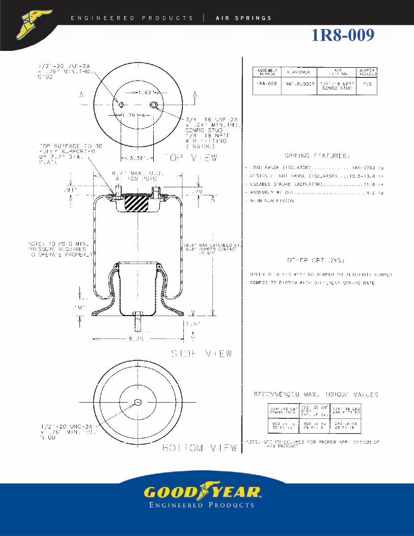
1R8-009

cpm Hz
500 18 80 74 1.231000 34 125 67 1.12
18.6 5.6 533 200 360 560 850 -- 1500 51 185 66 1.1017.0 4.5 501 440 800 1150 1600 -- 2000 67 240 65 1.0816.0 4.3 474 520 1000 1450 1900 -- 2500 81 290 64 1.0714.5 3.9 429 500 1050 1700 2300 -- 500 18 105 87 1.4513.0 3.3 381 480 1050 1700 2300 2900 1000 36 150 72 1.2011.5 2.1 334 460 1000 1700 2200 2800 1500 53 185 66 1.1010.5 1.4 305 480 1000 1600 2100 2700 2000 70 235 64 1.079.0 0.9 264 700 1150 1800 2300 2900 2500 86 250 59 0.988.0 0.6 235 700 1450 2200 2700 3400 500 19 150 102 1.706.8 0.5 196 750 1600 2500 3200 3900 1000 37 180 80 1.33
1500 54 205 70 1.172000 71 260 68 1.132500 89 285 63 1.05
**NOTE: MAXIMUM INFLATION PRESSURE IS 100 PSIG. MAXIMUM JOUNCE PRESSURE IS 200 PSIG. IF YOUR APPLICATION WILL EXCEED THESE LIMITS, CONSULT A GOODYEAR ENGINEERED PRODUCTS AIR SPRINGS
REPRESENTATIVE FOR APPLICATION ASSISTANCE.CONSTANT PRESSURE CHARACTERISTICS DYNAMIC CHARACTERISTICS
AssemblyHeight (in)
MeniscusHeight "M" Dim. @ 100 PSIG (in)
Volume @ 100 PSIG
(in3)
Nominal Force (lb)DesignHeight
(in)
Load(lb)
Pressure(PSIG)
SpringRate
(lb/in)
11.5
10.5
NaturalFrequency
@ 100 PSIG
13.0
@ 20 PSIG
@ 40 PSIG
@ 60 PSIG
@ 80 PSIG
LOAD vs. DEFLECTION @ CONSTANT PRESSURE
0
500
1000
1500
2000
2500
3000
3500
4000
4500
6.5 7.5 8.5 9.5 10.5 11.5 12.5 13.5 14.5 15.5 16.5 17.5 18.5
HEIGHT (in)
LOA
D (l
bf)
DESIGNHEIGHTRANGE
(ISOLATOR)COMPRESSED
HEIGHT
20
40
60
80
100 PSIG
MAX EXT HEIGHT
6.8 18.6
DYNAMIC DATA @ 11.5 in DESIGN HEIGHT
0
50
100
150
200
6.5 7.5 8.5 9.5 10.5 11.5 12.5 13.5 14.5 15.5 16.5 17.5 18.5
HEIGHT (in)
PRES
SUR
E (P
SIG
)
COMPRESSEDHEIGHT
MAX EXT HEIGHT
DESIGNHEIGHT
P1
P2
P3
P4
P5
6.8 18.6
DYNAMIC DATA @ 11.5 in DESIGN HEIGHT
0
1000
2000
3000
4000
5000
6000
7000
8000
6.5 7.5 8.5 9.5 10.5 11.5 12.5 13.5 14.5 15.5 16.5 17.5 18.5HEIGHT (in)
LOA
D (l
bf)
COMPRESSEDHEIGHT
MAX EXT HEIGHT
DESIGNHEIGHT
L1
L2
L3
L4
L5
6.8 18.6
GRAPHS FOR REFERENCE ONLY - USE THE CHART DATA BELOW FOR DESIGN WORK 1R8-009

1R9-003

cpm Hz
500 17 100 85 1.421500 48 215 71 1.18
17.9 5.9 610 220 400 640 900 1250 2500 78 330 68 1.1317.0 5.4 592 400 680 1000 1400 1800 3000 92 370 66 1.1016.0 4.8 567 450 900 1350 1800 2300 500 15 165 107 1.7814.0 3.8 504 540 1100 1700 2300 3000 1500 47 295 83 1.3812.0 2.8 434 560 1150 1800 2500 3200 2500 76 440 78 1.3010.0 1.7 366 600 1200 1900 2600 3300 3000 90 515 77 1.288.0 0.9 297 800 1500 2200 2900 3700 500 18 210 121 2.027.0 0.5 260 900 1600 2400 3200 4100 1500 39 435 102 1.706.0 0.3 222 1050 1900 2700 3700 4600 2500 67 675 98 1.635.6 0.2 206 1150 2000 2900 3900 4900 3000 80 785 96 1.60
3500 93 895 95 1.58
NaturalFrequency
@ 100 PSIG
@ 20 PSIG
@ 40 PSIG
@ 60 PSIG
@ 80 PSIG
DesignHeight
(in)
Load(lb)
Pressure(PSIG)
SpringRate
(lb/in)
12.0
10.0
8.0
**NOTE: MAXIMUM INFLATION PRESSURE IS 100 PSIG. MAXIMUM JOUNCE PRESSURE IS 200 PSIG. IF YOUR APPLICATION WILL EXCEED THESE LIMITS, CONSULT A GOODYEAR ENGINEERED PRODUCTS AIR SPRINGS
REPRESENTATIVE FOR APPLICATION ASSISTANCE.CONSTANT PRESSURE CHARACTERISTICS DYNAMIC CHARACTERISTICS
AssemblyHeight (in)
MeniscusHeight "M" Dim. @ 100 PSIG (in)
Volume@ 100
PSIG (in3)
Nominal Force (lb)
LOAD vs. DEFLECTION @ CONSTANT PRESSURE
0
500
1000
1500
2000
2500
3000
3500
4000
4500
5000
5.5 6.5 7.5 8.5 9.5 10.5 11.5 12.5 13.5 14.5 15.5 16.5 17.5
HEIGHT (in)
LOA
D (l
bf)
DESIGNHEIGHTRANGE
(ISOLATOR)COMPRESSED
HEIGHT
20
40
60
80
100 PSIG
MAX EXT HEIGHT
5.6 17.9
DYNAMIC DATA @ 10.0 in DESIGN HEIGHT
0
50
100
150
200
5.5 6.5 7.5 8.5 9.5 10.5 11.5 12.5 13.5 14.5 15.5 16.5 17.5
HEIGHT (in)
PRES
SUR
E (P
SIG
)
COMPRESSEDHEIGHT
MAX EXT HEIGHT
DESIGNHEIGHT
P1
P2
P3
P4
5.6 17.9
DYNAMIC DATA @ 10.0 in DESIGN HEIGHT
0
2000
4000
6000
8000
10000
12000
5.5 6.5 7.5 8.5 9.5 10.5 11.5 12.5 13.5 14.5 15.5 16.5 17.5HEIGHT (in)
LOA
D (l
bf)
COMPRESSEDHEIGHT
MAX EXT HEIGHT
DESIGNHEIGHT
L1
L2
L3
L4
5.6 17.9
GRAPHS FOR REFERENCE ONLY - USE THE CHART DATA BELOW FOR DESIGN WORK 1R9-003
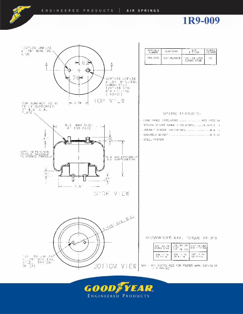
1R9-009

cpm Hz
500 14 185 114 1.901500 37 455 103 1.72
11.8 2.5 436 180 330 500 700 900 2500 62 790 106 1.7710.5 2.3 388 460 750 1150 1500 2000 3500 87 1120 106 1.779.5 2.1 358 640 1100 1600 2100 2700 500 13 230 128 2.138.5 2.0 325 800 1400 2000 2700 3300 1500 36 430 101 1.687.5 1.9 287 800 1600 2400 3100 3900 2500 58 740 102 1.706.7 1.8 257 700 1700 2600 3400 4300 3500 81 1040 102 1.706.0 1.7 228 800 1500 2500 3500 4400 500 11 280 140 2.335.0 0.5 181 900 1600 2400 3300 4400 1500 39 525 111 1.854.0 0.9 135 1150 1900 2700 3600 4600 2500 61 685 98 1.633.2 0.0 100 1850 2600 3400 4400 5300 3500 82 920 96 1.60
6.0
@ 100 PSIG
@ 20 PSIG
@ 40 PSIG
@ 60 PSIG
@ 80 PSIG
SpringRate
(lb/in)
NaturalFrequency
7.5
6.7
**NOTE: MAXIMUM INFLATION PRESSURE IS 100 PSIG. MAXIMUM JOUNCE PRESSURE IS 200 PSIG. IF YOUR APPLICATION WILL EXCEED THESE LIMITS, CONSULT A GOODYEAR ENGINEERED PRODUCTS AIR SPRINGS
REPRESENTATIVE FOR APPLICATION ASSISTANCE.CONSTANT PRESSURE CHARACTERISTICS DYNAMIC CHARACTERISTICS
AssemblyHeight (in)
MeniscusHeight "M" Dim. @ 100 PSIG (in)
Volume@ 100
PSIG (in3)
Nominal Force (lb)DesignHeight
(in)
Load(lb)
Pressure(PSIG)
LOAD vs. DEFLECTION @ CONSTANT PRESSURE
0
500
1000
1500
2000
2500
3000
3500
4000
4500
5000
5500
3.0 4.0 5.0 6.0 7.0 8.0 9.0 10.0 11.0 12.0
HEIGHT (in)
LOA
D (l
bf)
DESIGNHEIGHTRANGE
(ISOLATOR)COMPRESSED
HEIGHT
20
40
60
80
100 PSIG
MAX EXT HEIGHT
3.2 11.8
DYNAMIC DATA @ 6.7 in DESIGN HEIGHT
0
50
100
150
200
3.0 4.0 5.0 6.0 7.0 8.0 9.0 10.0 11.0 12.0
HEIGHT (in)
PRES
SUR
E (P
SIG
)
COMPRESSEDHEIGHT
MAX EXT HEIGHT
DESIGNHEIGHT
P1
P2
P3 P4
3.2 11.86.7
DYNAMIC DATA @ 6.7 in DESIGN HEIGHT
0
2000
4000
6000
8000
10000
12000
14000
3.0 4.0 5.0 6.0 7.0 8.0 9.0 10.0 11.0 12.0HEIGHT (in)
LOA
D (l
bf)
COMPRESSEDHEIGHT
MAX EXT HEIGHT
DESIGNHEIGHT
L1
L2
L3L4
3.2 11.86.7
GRAPHS FOR REFERENCE ONLY - USE THE CHART DATA BELOW FOR DESIGN WORK 1R9-009

1R10-089

cpm Hz
1000 19 175 79 1.322000 37 130 48 0.80
20.1 4.5 1125 250 580 950 1500 2100 3000 53 105 35 0.5819.0 4.5 1080 420 900 1500 2100 2800 4000 70 175 40 0.6717.0 4.5 978 850 1600 2400 3400 4300 5000 87 245 41 0.6815.0 4.3 860 1100 2100 3200 4200 5300 1000 19 205 85 1.4213.5 3.4 766 900 1900 2900 4000 5200 2000 38 315 75 1.2511.5 2.2 651 900 1900 2900 4000 5000 3000 56 410 69 1.159.5 1.1 544 900 1900 3000 4100 5200 4000 74 510 67 1.128.0 0.7 462 1100 2300 3500 4800 6000 5000 91 600 65 1.087.0 0.4 401 1300 2600 3900 5300 6700 1000 18 325 107 1.786.0 0.4 335 1500 2900 4400 5800 7300 2000 37 460 90 1.50
3000 56 595 84 1.404000 73 750 82 1.375000 90 875 79 1.32
**NOTE: MAXIMUM INFLATION PRESSURE IS 100 PSIG. MAXIMUM JOUNCE PRESSURE IS 200 PSIG. IF YOUR APPLICATION WILL EXCEED THESE LIMITS, CONSULT A GOODYEAR ENGINEERED PRODUCTS AIR SPRINGS
REPRESENTATIVE FOR APPLICATION ASSISTANCE.CONSTANT PRESSURE CHARACTERISTICS DYNAMIC CHARACTERISTICS
AssemblyHeight (in)
MeniscusHeight "M" Dim. @ 100 PSIG (in)
Volume @ 100 PSIG
(in3)
Nominal Force (lb)DesignHeight
(in)
Load(lb)
Pressure(PSIG)
SpringRate
(lb/in)
11.5
9.5
NaturalFrequency
@ 100 PSIG
13.5
@ 20 PSIG
@ 40 PSIG
@ 60 PSIG
@ 80 PSIG
LOAD vs. DEFLECTION @ CONSTANT PRESSURE
0
1000
2000
3000
4000
5000
6000
7000
8000
5.5 7.5 9.5 11.5 13.5 15.5 17.5 19.5
HEIGHT (in)
LOA
D (l
bf)
DESIGNHEIGHTRANGE
(ISOLATOR)COMPRESSED
HEIGHT
20
40
60
80
100 PSIG
MAX EXT HEIGHT
6.0 20.1
DYNAMIC DATA @ 11.5 in DESIGN HEIGHT
0
50
100
150
200
5.5 7.5 9.5 11.5 13.5 15.5 17.5 19.5
HEIGHT (in)
PRES
SUR
E (P
SIG
)
COMPRESSEDHEIGHT
MAX EXT HEIGHT
DESIGNHEIGHT
P1
P2
P3
P4 P5
6.0 20.1
DYNAMIC DATA @ 11.5 in DESIGN HEIGHT
0
2000
4000
6000
8000
10000
12000
5.5 7.5 9.5 11.5 13.5 15.5 17.5 19.5HEIGHT (in)
LOA
D (l
bf)
COMPRESSEDHEIGHT
MAX EXT HEIGHT
DESIGNHEIGHT
L1
L2
L3
L4 L5
6.0 20.1
GRAPHS FOR REFERENCE ONLY - USE THE CHART DATA BELOW FOR DESIGN WORK 1R10-089

1R11-028

cpm Hz
2000 37 630 105 1.753000 56 910 103 1.72
13.0 1.9 699 60 460 1100 1800 2300 5000 93 1425 100 1.6711.0 1.9 696 850 1700 2700 3600 4600 2000 31 500 94 1.5710.0 1.9 635 1100 2200 3200 4300 5500 3000 46 690 91 1.529.0 1.6 570 1150 2400 3600 4900 5800 5000 75 1120 90 1.508.0 1.4 501 1200 2600 3900 5300 6600 6000 89 1320 89 1.487.0 0.6 433 1200 2500 3800 5200 6500 2000 29 1000 133 2.226.0 0.1 369 1400 2700 4000 5400 6700 3000 45 1315 124 2.075.0 0.1 304 1700 3100 4600 6100 7600 5000 74 1855 115 1.924.0 0.0 250 1800 3400 5000 6600 8200 6000 89 2180 113 1.883.7 0.0 225 2100 3600 5100 6700 8300
Load(lb)
Pressure(PSIG)
SpringRate
(lb/in)
NaturalFrequency
**NOTE: MAXIMUM INFLATION PRESSURE IS 100 PSIG. MAXIMUM JOUNCE PRESSURE IS 200 PSIG. IF YOUR APPLICATION WILL EXCEED THESE LIMITS, CONSULT A GOODYEAR ENGINEERED PRODUCTS AIR SPRINGS
REPRESENTATIVE FOR APPLICATION ASSISTANCE.CONSTANT PRESSURE CHARACTERISTICS DYNAMIC CHARACTERISTICS
AssemblyHeight (in)
MeniscusHeight "M" Dim. @ 100 PSIG (in)
Volume@ 100
PSIG (in3)
Nominal Force (lb)DesignHeight
(in)
@ 20 PSIG
@ 40 PSIG
6.0
@ 100 PSIG
@ 60 PSIG
@ 80 PSIG 10.0
8.0
LOAD vs. DEFLECTION @ CONSTANT PRESSURE
0
500
1000
1500
2000
2500
3000
3500
4000
4500
5000
5500
6000
6500
7000
7500
8000
8500
3.5 4.5 5.5 6.5 7.5 8.5 9.5 10.5 11.5 12.5
HEIGHT (in)
LOA
D (l
bf)
DESIGNHEIGHTRANGE
(ISOLATOR)COMPRESSED
HEIGHT
20
40
60
80
100 PSIG
MAX EXT HEIGHT
3.7 13.0
DYNAMIC DATA @ 8.0 in DESIGN HEIGHT
0
50
100
150
200
3.5 4.5 5.5 6.5 7.5 8.5 9.5 10.5 11.5 12.5
HEIGHT (in)
PRES
SUR
E (P
SIG
)
COMPRESSEDHEIGHT
MAX EXT HEIGHT
DESIGNHEIGHT
P1
P2
P3 P4
3.7 13.0
DYNAMIC DATA @ 8.0 in DESIGN HEIGHT
0
2000
4000
6000
8000
10000
12000
14000
16000
18000
3.5 4.5 5.5 6.5 7.5 8.5 9.5 10.5 11.5 12.5HEIGHT (in)
LOA
D (l
bf)
COMPRESSEDHEIGHT
MAX EXT HEIGHT
DESIGNHEIGHT
L1
L2
L3 L4
3.7 13.0
GRAPHS FOR REFERENCE ONLY - USE THE CHART DATA BELOW FOR DESIGN WORK 1R11-028

1R11-039

cpm Hz
2000 31 455 90 1.504000 62 765 82 1.37
17.1 4.8 936 560 900 1350 1800 2300 5000 78 910 80 1.3316.0 4.6 887 950 1600 2300 3000 3700 6000 93 1020 78 1.3015.0 4.3 830 1200 2100 3000 3800 4800 2000 30 605 103 1.7214.0 4.1 762 1250 2400 3500 4600 5700 4000 60 1025 95 1.5813.0 3.7 686 1250 2500 3800 5100 6300 5000 75 1245 94 1.5712.0 3.3 609 1300 2500 3800 5100 6500 6000 90 1430 92 1.5310.0 2.1 463 1300 2600 4000 5300 6700 2000 27 920 127 2.128.0 1.1 326 1500 2800 4200 5600 7000 4000 57 1535 116 1.937.0 0.6 263 1700 3100 4600 6000 7500 5000 72 1865 114 1.906.1 0.4 212 1500 3300 4900 6300 7900 6000 85 2110 112 1.87
7000 99 2435 111 1.85
10.0
@ 100 PSIG
@ 20 PSIG
@ 40 PSIG
@ 60 PSIG
@ 80 PSIG
Pressure(PSIG)
SpringRate
(lb/in)
NaturalFrequency
12.0
8.0
**NOTE: MAXIMUM INFLATION PRESSURE IS 100 PSIG. MAXIMUM JOUNCE PRESSURE IS 200 PSIG. IF YOUR APPLICATION WILL EXCEED THESE LIMITS, CONSULT A GOODYEAR ENGINEERED PRODUCTS AIR SPRINGS
REPRESENTATIVE FOR APPLICATION ASSISTANCE.CONSTANT PRESSURE CHARACTERISTICS DYNAMIC CHARACTERISTICS
AssemblyHeight (in)
MeniscusHeight "M" Dim. @ 100 PSIG (in)
Volume@ 100
PSIG (in3)
Nominal Force (lb)DesignHeight
(in)
Load(lb)
LOAD vs. DEFLECTION @ CONSTANT PRESSURE
0
500
1000
1500
2000
2500
3000
3500
4000
4500
5000
5500
6000
6500
7000
7500
8000
6.0 7.0 8.0 9.0 10.0 11.0 12.0 13.0 14.0 15.0 16.0 17.0
HEIGHT (in)
LOA
D (l
bf)
DESIGNHEIGHTRANGE
(ISOLATOR)COMPRESSED
HEIGHT
20
40
60
80
100 PSIG
MAX EXT HEIGHT
6.1 17.1
DYNAMIC DATA @ 10.0 in DESIGN HEIGHT
0
50
100
150
200
6.0 7.0 8.0 9.0 10.0 11.0 12.0 13.0 14.0 15.0 16.0 17.0
HEIGHT (in)
PRES
SUR
E (P
SIG
)
COMPRESSEDHEIGHT
MAX EXT HEIGHT
DESIGNHEIGHT
P1
P2
P3 P4
6.1 17.1
DYNAMIC DATA @ 10.0 in DESIGN HEIGHT
0
2000
4000
6000
8000
10000
12000
14000
16000
18000
6.0 7.0 8.0 9.0 10.0 11.0 12.0 13.0 14.0 15.0 16.0 17.0HEIGHT (in)
LOA
D (l
bf)
COMPRESSEDHEIGHT
MAX EXT HEIGHT
DESIGNHEIGHT
L1
L2
L3 L4
6.1 17.1
GRAPHS FOR REFERENCE ONLY - USE THE CHART DATA BELOW FOR DESIGN WORK 1R11-039

1R12-092

cpm Hz
2000 29 395 84 1.403000 43 580 83 1.38
21.1 5.9 1330 320 620 1200 1700 2700 5000 71 900 80 1.3320.0 5.7 1259 680 1350 2100 3000 4100 6000 86 1065 79 1.3218.0 5.5 1124 1200 2200 3400 4600 5900 7000 100 1210 78 1.3016.5 5.1 1010 1350 2700 3900 5300 6800 2000 29 425 86 1.4315.0 4.4 891 1300 2700 4200 5700 7300 3000 43 585 83 1.3813.3 3.4 762 1350 2800 4200 5700 7300 5000 69 830 77 1.2812.0 2.7 634 1400 2800 4300 5800 7400 6000 83 960 75 1.2510.5 1.8 563 1400 2900 4400 5900 7600 7000 95 1090 74 1.239.0 1.1 463 1500 3000 4500 6100 4800 2000 27 625 105 1.757.7 0.5 379 1600 3200 4700 6400 8100 3000 41 795 97 1.62
5000 68 1160 90 1.506000 80 1315 88 1.477000 94 1485 86 1.43
@ 100 PSIG
16.5
@ 20 PSIG
@ 40 PSIG
@ 60 PSIG
@ 80 PSIG
SpringRate
(lb/in)
13.3
10.5
NaturalFrequency
**NOTE: MAXIMUM INFLATION PRESSURE IS 100 PSIG. MAXIMUM JOUNCE PRESSURE IS 200 PSIG. IF YOUR APPLICATION WILL EXCEED THESE LIMITS, CONSULT A GOODYEAR ENGINEERED PRODUCTS AIR SPRINGS
REPRESENTATIVE FOR APPLICATION ASSISTANCE.CONSTANT PRESSURE CHARACTERISTICS DYNAMIC CHARACTERISTICS
AssemblyHeight (in)
MeniscusHeight "M" Dim. @ 100 PSIG (in)
Volume@ 100
PSIG (in3)
Nominal Force (lb)DesignHeight
(in)
Load(lb)
Pressure(PSIG)
LOAD vs. DEFLECTION @ CONSTANT PRESSURE
0
1000
2000
3000
4000
5000
6000
7000
8000
9000
7.5 9.0 10.5 12.0 13.5 15.0 16.5 18.0 19.5 21.0
HEIGHT (in)
LOA
D (l
bf)
DESIGNHEIGHTRANGE
(ISOLATOR)COMPRESSED
HEIGHT
20
40
60
80
100 PSIG
MAX EXT HEIGHT
7.7 21.1
DYNAMIC DATA @ 13.3 in DESIGN HEIGHT
0
50
100
150
200
7.5 9.0 10.5 12.0 13.5 15.0 16.5 18.0 19.5 21.0
HEIGHT (in)
PRES
SUR
E (P
SIG
)
COMPRESSEDHEIGHT
MAX EXT HEIGHT
DESIGNHEIGHT
P1
P2
P3 P4 P5
7.7 21.113.3
DYNAMIC DATA @ 13.3 in DESIGN HEIGHT
0
2000
4000
6000
8000
10000
12000
14000
16000
18000
20000
7.5 9.0 10.5 12.0 13.5 15.0 16.5 18.0 19.5 21.0HEIGHT (in)
LOA
D (l
bf)
COMPRESSEDHEIGHT
MAX EXT HEIGHT
DESIGNHEIGHT
L1
L2
L3
L4 L5
7.7 21.113.3
GRAPHS FOR REFERENCE ONLY - USE THE CHART DATA BELOW FOR DESIGN WORK 1R12-092
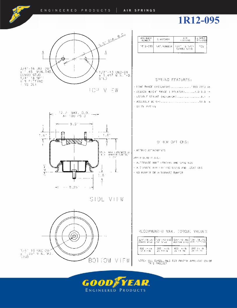
1R12-095

cpm Hz
2000 29 605 103 1.723000 43 845 100 1.67
13.5 2.1 875 240 400 1000 1700 2400 4000 58 1090 98 1.6312.0 2.1 777 750 1500 2400 3300 4300 6000 87 1515 94 1.5711.0 2.1 713 1080 2000 3100 4200 5400 7000 100 1730 93 1.5510.0 1.8 646 1250 2400 3600 4900 6200 2000 28 575 100 1.679.0 1.5 574 1350 2700 4000 5400 6800 3000 42 755 94 1.578.0 1.1 501 1350 2700 4300 5800 7300 4000 55 975 93 1.557.0 0.4 431 1350 2700 4200 5700 7300 6000 83 1430 91 1.526.0 0.3 364 1500 2900 4400 5900 7500 7000 96 1615 90 1.505.0 0.1 296 1700 3300 4900 6600 8200 2000 29 680 109 1.824.4 0.0 256 1800 3300 5100 6800 8600 3000 43 865 101 1.68
4000 57 1045 96 1.606000 84 1295 88 1.477000 98 1500 87 1.45
@ 100 PSIG
9.0
@ 20 PSIG
@ 40 PSIG
@ 60 PSIG
@ 80 PSIG
SpringRate
(lb/in)
8.0
7.0
NaturalFrequency
**NOTE: MAXIMUM INFLATION PRESSURE IS 100 PSIG. MAXIMUM JOUNCE PRESSURE IS 200 PSIG. IF YOUR APPLICATION WILL EXCEED THESE LIMITS, CONSULT A GOODYEAR ENGINEERED PRODUCTS AIR SPRINGS
REPRESENTATIVE FOR APPLICATION ASSISTANCE.CONSTANT PRESSURE CHARACTERISTICS DYNAMIC CHARACTERISTICS
AssemblyHeight (in)
MeniscusHeight "M" Dim. @ 100 PSIG (in)
Volume @ 100 PSIG
(in3)
Nominal Force (lb)DesignHeight
(in)
Load(lb)
Pressure(PSIG)
LOAD vs. DEFLECTION @ CONSTANT PRESSURE
0
1000
2000
3000
4000
5000
6000
7000
8000
9000
4.0 5.0 6.0 7.0 8.0 9.0 10.0 11.0 12.0 13.0
HEIGHT (in)
LOA
D (l
bf)
DESIGNHEIGHTRANGE
(ISOLATOR)COMPRESSED
HEIGHT
20
40
60
80
100 PSIG
MAX EXT HEIGHT
4.4
DYNAMIC DATA @ 8.0 in DESIGN HEIGHT
0
50
100
150
200
4.0 5.0 6.0 7.0 8.0 9.0 10.0 11.0 12.0 13.0
HEIGHT (in)
PRES
SUR
E (P
SIG
)
COMPRESSEDHEIGHT
MAX EXT HEIGHT
DESIGNHEIGHT
P1
P2
P3
P4 P5
4.4
DYNAMIC DATA @ 8.0 in DESIGN HEIGHT
0
2000
4000
6000
8000
10000
12000
14000
16000
18000
4.0 5.0 6.0 7.0 8.0 9.0 10.0 11.0 12.0 13.0HEIGHT (in)
LOA
D (l
bf)
COMPRESSEDHEIGHT
MAX EXT HEIGHT
DESIGNHEIGHT
L1
L2
L3
L4 L5
4.4
GRAPHS FOR REFERENCE ONLY - USE THE CHART DATA BELOW FOR DESIGN WORK 1R12-095

1R12-103
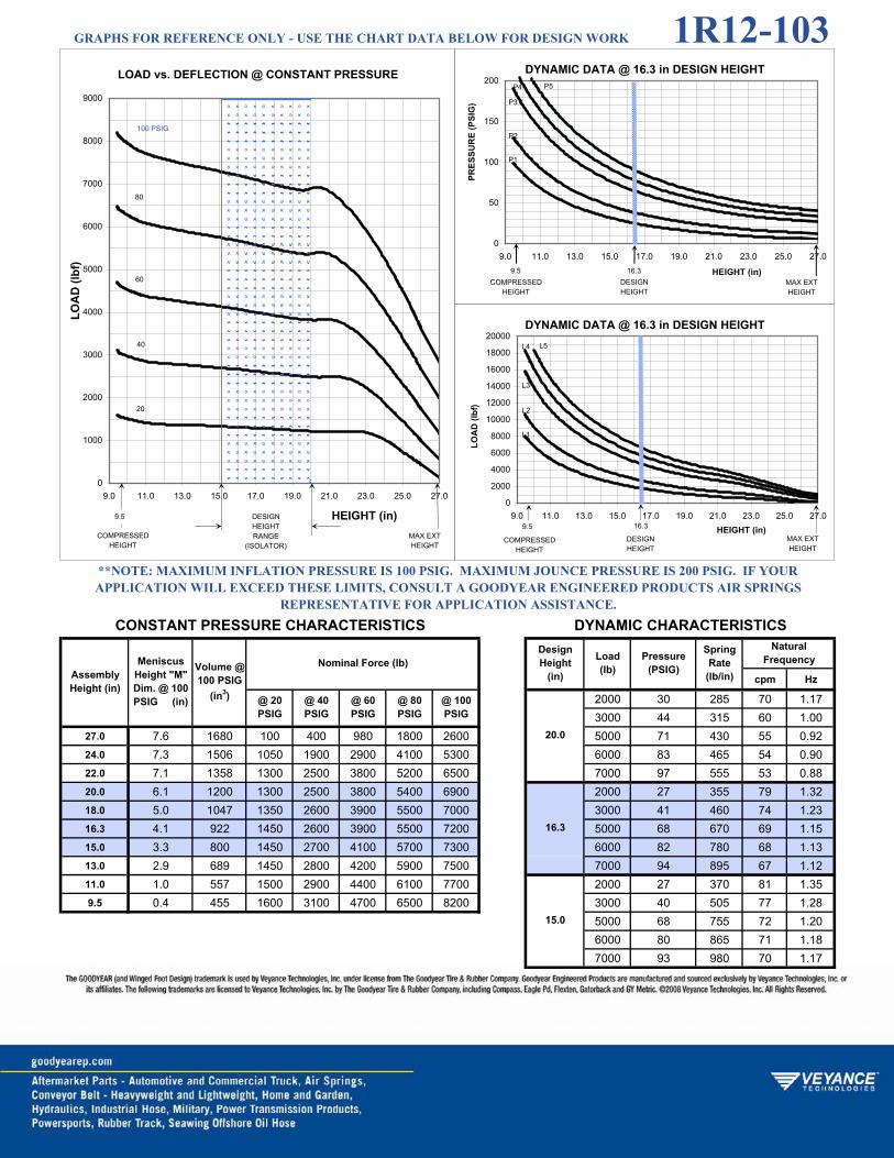
cpm Hz
2000 30 285 70 1.173000 44 315 60 1.00
27.0 7.6 1680 100 400 980 1800 2600 5000 71 430 55 0.9224.0 7.3 1506 1050 1900 2900 4100 5300 6000 83 465 54 0.9022.0 7.1 1358 1300 2500 3800 5200 6500 7000 97 555 53 0.8820.0 6.1 1200 1300 2500 3800 5400 6900 2000 27 355 79 1.3218.0 5.0 1047 1350 2600 3900 5500 7000 3000 41 460 74 1.2316.3 4.1 922 1450 2600 3900 5500 7200 5000 68 670 69 1.1515.0 3.3 800 1450 2700 4100 5700 7300 6000 82 780 68 1.1313.0 2.9 689 1450 2800 4200 5900 7500 7000 94 895 67 1.1211.0 1.0 557 1500 2900 4400 6100 7700 2000 27 370 81 1.359.5 0.4 455 1600 3100 4700 6500 8200 3000 40 505 77 1.28
5000 68 755 72 1.206000 80 865 71 1.187000 93 980 70 1.17
@ 100 PSIG
20.0
@ 20 PSIG
@ 40 PSIG
@ 60 PSIG
@ 80 PSIG
SpringRate
(lb/in)
16.3
15.0
NaturalFrequency
**NOTE: MAXIMUM INFLATION PRESSURE IS 100 PSIG. MAXIMUM JOUNCE PRESSURE IS 200 PSIG. IF YOUR APPLICATION WILL EXCEED THESE LIMITS, CONSULT A GOODYEAR ENGINEERED PRODUCTS AIR SPRINGS
REPRESENTATIVE FOR APPLICATION ASSISTANCE.CONSTANT PRESSURE CHARACTERISTICS DYNAMIC CHARACTERISTICS
AssemblyHeight (in)
MeniscusHeight "M" Dim. @ 100 PSIG (in)
Volume @ 100 PSIG
(in3)
Nominal Force (lb)DesignHeight
(in)
Load(lb)
Pressure(PSIG)
LOAD vs. DEFLECTION @ CONSTANT PRESSURE
0
1000
2000
3000
4000
5000
6000
7000
8000
9000
9.0 11.0 13.0 15.0 17.0 19.0 21.0 23.0 25.0 27.0
HEIGHT (in)
LOA
D (l
bf)
DESIGNHEIGHTRANGE
(ISOLATOR)COMPRESSED
HEIGHT
20
40
60
80
100 PSIG
MAX EXT HEIGHT
9.5
DYNAMIC DATA @ 16.3 in DESIGN HEIGHT
0
50
100
150
200
9.0 11.0 13.0 15.0 17.0 19.0 21.0 23.0 25.0 27.0
HEIGHT (in)
PRES
SUR
E (P
SIG
)
COMPRESSEDHEIGHT
MAX EXT HEIGHT
DESIGNHEIGHT
P1
P2
P3
P4 P5
16.39.5
DYNAMIC DATA @ 16.3 in DESIGN HEIGHT
0
2000
4000
6000
8000
10000
12000
14000
16000
18000
20000
9.0 11.0 13.0 15.0 17.0 19.0 21.0 23.0 25.0 27.0HEIGHT (in)
LOA
D (l
bf)
COMPRESSEDHEIGHT
MAX EXT HEIGHT
DESIGNHEIGHT
L1
L2
L3
L4 L5
16.39.5
GRAPHS FOR REFERENCE ONLY - USE THE CHART DATA BELOW FOR DESIGN WORK 1R12-103

1R12-132

cpm Hz
2000 28 550 98 1.633000 42 700 91 1.52
16.9 4.1 1089 220 620 1200 1900 2700 4000 55 900 89 1.4815.0 4.1 983 950 1800 2800 3900 5100 6000 81 1190 83 1.3813.0 3.7 834 1300 2600 3800 5300 6600 7000 94 1335 82 1.3712.0 3.3 753 1350 2800 4000 5500 7100 2000 27 655 107 1.7811.0 2.8 672 1350 2800 4100 5600 7200 3000 41 840 99 1.6510.0 2.3 595 1400 2800 4200 5700 7400 4000 54 1035 95 1.589.0 1.7 521 1400 2900 4300 5800 7500 6000 80 1400 91 1.528.0 1.1 448 1450 2900 4400 6000 7600 7000 93 1595 89 1.487.0 0.7 378 1500 3100 4700 6300 7900 2000 27 780 117 1.956.1 0.3 320 1700 3300 5000 6700 8400 3000 40 1025 109 1.82
4000 54 1260 105 1.756000 79 1660 99 1.657000 92 1905 98 1.63
@ 100 PSIG
10.0
@ 20 PSIG
@ 40 PSIG
@ 60 PSIG
@ 80 PSIG
SpringRate
(lb/in)
9.0
8.0
NaturalFrequency
**NOTE: MAXIMUM INFLATION PRESSURE IS 100 PSIG. MAXIMUM JOUNCE PRESSURE IS 200 PSIG. IF YOUR APPLICATION WILL EXCEED THESE LIMITS, CONSULT A GOODYEAR ENGINEERED PRODUCTS AIR SPRINGS
REPRESENTATIVE FOR APPLICATION ASSISTANCE.CONSTANT PRESSURE CHARACTERISTICS DYNAMIC CHARACTERISTICS
AssemblyHeight (in)
MeniscusHeight "M" Dim. @ 100 PSIG (in)
Volume@ 100
PSIG (in3)
Nominal Force (lb)DesignHeight
(in)
Load(lb)
Pressure(PSIG)
LOAD vs. DEFLECTION @ CONSTANT PRESSURE
0
1000
2000
3000
4000
5000
6000
7000
8000
9000
6.0 7.0 8.0 9.0 10.0 11.0 12.0 13.0 14.0 15.0 16.0 17.0
HEIGHT (in)
LOA
D (l
bf)
DESIGNHEIGHTRANGE
(ISOLATOR)COMPRESSED
HEIGHT
20
40
60
80
100 PSIG
MAX EXT HEIGHT
6.1 16.9
DYNAMIC DATA @ 9.0 in DESIGN HEIGHT
0
50
100
150
200
6.0 7.0 8.0 9.0 10.0 11.0 12.0 13.0 14.0 15.0 16.0 17.0
HEIGHT (in)
PRES
SUR
E (P
SIG
)
COMPRESSEDHEIGHT
MAX EXT HEIGHT
DESIGNHEIGHT
P1
P2
P3
P4
P5
6.1 16.9
DYNAMIC DATA @ 9.0 in DESIGN HEIGHT
0
2000
4000
6000
8000
10000
12000
14000
16000
6.0 7.0 8.0 9.0 10.0 11.0 12.0 13.0 14.0 15.0 16.0 17.0HEIGHT (in)
LOA
D (l
bf)
COMPRESSEDHEIGHT
MAX EXT HEIGHT
DESIGNHEIGHT
L1
L2
L3
L4
L5
6.1 16.9
GRAPHS FOR REFERENCE ONLY - USE THE CHART DATA BELOW FOR DESIGN WORK 1R12-132

1R12-256

cpm Hz
2000 28 270 69 1.153000 42 350 64 1.07
29.1 8.1 1760 320 850 1500 2200 3100 4500 63 465 60 1.0026.0 7.6 1596 1100 2000 3100 4300 5500 6000 83 580 58 0.9724.0 7.2 1462 1300 2500 3900 5200 6500 2000 28 290 71 1.1822.0 6.5 1317 1300 2600 4000 5500 7000 3000 42 405 69 1.1520.0 5.2 1174 1350 2600 4100 5500 7000 4500 62 535 65 1.0818.0 4.1 1036 1400 2700 4200 5600 7200 6000 81 655 62 1.0316.0 2.9 899 1450 2800 4300 5800 7300 7500 100 790 61 1.0214.0 1.7 767 1500 2900 4400 5900 7500 2000 27 345 78 1.3012.0 0.7 640 1500 3000 4600 6200 7800 3000 41 455 73 1.229.5 0.0 429 1900 3400 5100 7100 9000 4500 61 600 69 1.15
6000 80 770 67 1.127500 99 910 65 1.08
20.0
18.0
16.0
**NOTE: MAXIMUM INFLATION PRESSURE IS 100 PSIG. MAXIMUM JOUNCE PRESSURE IS 200 PSIG. IF YOUR APPLICATION WILL EXCEED THESE LIMITS, CONSULT A GOODYEAR ENGINEERED PRODUCTS AIR SPRINGS
REPRESENTATIVE FOR APPLICATION ASSISTANCE.CONSTANT PRESSURE CHARACTERISTICS DYNAMIC CHARACTERISTICS
AssemblyHeight (in)
MeniscusHeight "M" Dim. @ 100 PSIG (in)
Volume@ 100
PSIG (in3)
Nominal Force (lb)Natural
Frequency
@ 100 PSIG
@ 20 PSIG
@ 40 PSIG
@ 60 PSIG
@ 80 PSIG
DesignHeight
(in)
Load(lb)
Pressure(PSIG)
SpringRate
(lb/in)
LOAD vs. DEFLECTION @ CONSTANT PRESSURE
0
1000
2000
3000
4000
5000
6000
7000
8000
9000
9.0 11.0 13.0 15.0 17.0 19.0 21.0 23.0 25.0 27.0 29.0
HEIGHT (in)
LOA
D (l
bf)
DESIGNHEIGHTRANGE
(ISOLATOR)COMPRESSED
HEIGHT
20
40
60
80
100 PSIG
MAX EXT HEIGHT
9.5 29.1
DYNAMIC DATA @ 18.0 in DESIGN HEIGHT
0
50
100
150
200
9.0 11.0 13.0 15.0 17.0 19.0 21.0 23.0 25.0 27.0 29.0
HEIGHT (in)
PRES
SUR
E (P
SIG
)
COMPRESSEDHEIGHT
MAX EXT HEIGHT
DESIGNHEIGHT
P1
P2
P3
P4 P5
29.19.5
DYNAMIC DATA @ 18.0 in DESIGN HEIGHT
0
2000
4000
6000
8000
10000
12000
14000
16000
18000
20000
9.0 11.0 13.0 15.0 17.0 19.0 21.0 23.0 25.0 27.0 29.0HEIGHT (in)
LOA
D (l
bf)
COMPRESSEDHEIGHT
MAX EXT HEIGHT
DESIGNHEIGHT
L1
L2
L3L4 L5
29.19.5
GRAPHS FOR REFERENCE ONLY - USE THE CHART DATA BELOW FOR DESIGN WORK 1R12-256

1R12-274

cpm Hz
2000 26 315 75 1.253000 39 420 71 1.18
22.8 4.8 1717 300 750 1450 2200 3000 5000 65 635 67 1.1222.0 4.8 1684 500 1150 1900 2900 3700 6000 78 725 66 1.1020.0 4.7 1574 1050 2000 2900 4200 5200 7000 90 850 65 1.0818.0 4.1 1419 1250 2500 3600 5100 6400 2000 27 315 74 1.2316.0 3.5 1248 1450 2700 4100 5800 7300 3000 40 405 69 1.1514.3 2.9 1111 1450 2800 4300 6000 7500 5000 67 565 63 1.0512.8 2.0 969 1400 2800 4200 6000 7500 6000 79 640 61 1.0211.3 1.0 864 1400 2700 4100 5800 7300 7000 92 700 59 0.9810.0 0.4 756 1600 2900 4500 6400 8000 2000 28 395 83 1.388.1 0.0 630 1700 3500 5200 7200 9000 3000 41 485 75 1.25
5000 69 725 71 1.186000 82 805 69 1.157000 94 880 67 1.12
@ 100 PSIG
14.3
@ 20 PSIG
@ 40 PSIG
@ 60 PSIG
@ 80 PSIG
SpringRate
(lb/in)
12.8
11.3
NaturalFrequency
**NOTE: MAXIMUM INFLATION PRESSURE IS 100 PSIG. MAXIMUM JOUNCE PRESSURE IS 200 PSIG. IF YOUR APPLICATION WILL EXCEED THESE LIMITS, CONSULT A GOODYEAR ENGINEERED PRODUCTS AIR SPRINGS
REPRESENTATIVE FOR APPLICATION ASSISTANCE.CONSTANT PRESSURE CHARACTERISTICS DYNAMIC CHARACTERISTICS
AssemblyHeight (in)
MeniscusHeight "M" Dim. @ 100 PSIG (in)
Volume @ 100 PSIG
(in3)
Nominal Force (lb)DesignHeight
(in)
Load(lb)
Pressure(PSIG)
LOAD vs. DEFLECTION @ CONSTANT PRESSURE
0
1000
2000
3000
4000
5000
6000
7000
8000
9000
8.0 9.5 11.0 12.5 14.0 15.5 17.0 18.5 20.0 21.5 23.0
HEIGHT (in)
LOA
D (l
bf)
DESIGNHEIGHTRANGE
(ISOLATOR)COMPRESSED
HEIGHT
20
40
60
80
100 PSIG
MAX EXT HEIGHT
8.1 22.8
DYNAMIC DATA @ 12.8 in DESIGN HEIGHT
0
50
100
150
200
8.0 9.5 11.0 12.5 14.0 15.5 17.0 18.5 20.0 21.5 23.0
HEIGHT (in)
PRES
SUR
E (P
SIG
)
COMPRESSEDHEIGHT
MAX EXT HEIGHT
DESIGNHEIGHT
P1
P2
P3
P4
P5
8.1 22.812.8
DYNAMIC DATA @ 12.8 in DESIGN HEIGHT
0
2000
4000
6000
8000
10000
12000
14000
16000
18000
20000
22000
8.0 9.5 11.0 12.5 14.0 15.5 17.0 18.5 20.0 21.5 23.0HEIGHT (in)
LOA
D (l
bf)
COMPRESSEDHEIGHT
MAX EXT HEIGHT
DESIGNHEIGHT
L1
L2L3
L4
L5
8.1 22.812.8
GRAPHS FOR REFERENCE ONLY - USE THE CHART DATA BELOW FOR DESIGN WORK 1R12-274

1R14-018
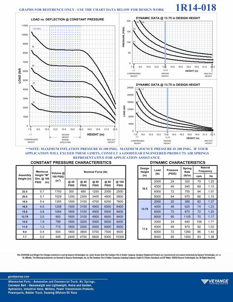
cpm Hz
2000 24 320 75 1.254000 49 540 69 1.15
22.5 5.7 1750 300 680 1250 2000 2500 6000 72 755 94 1.5720.0 5.7 1529 1250 2300 3400 4600 5800 8000 94 970 66 1.1018.0 5.4 1355 1500 3100 4700 6200 7600 2000 25 385 82 1.3716.5 4.5 1208 1500 3100 4900 6500 8400 4000 48 625 74 1.2315.0 3.8 1064 1600 3100 4900 6500 8400 6000 72 875 72 1.2013.75 3.0 950 1600 3100 4900 6600 8400 8000 95 1105 70 1.1712.0 1.9 799 1600 3200 5000 6600 8400 2000 24 640 106 1.7711.0 1.3 715 1600 3300 5000 6600 8500 4000 49 970 92 1.539.0 0.4 554 1800 3800 5700 7500 9500 6000 72 1260 86 1.437.7 0.0 409 2400 4700 6600 8300 10300 8000 95 1550 83 1.38
11.0
@ 100 PSIG
@ 60 PSIG
@ 80 PSIG
16.5
13.75
**NOTE: MAXIMUM INFLATION PRESSURE IS 100 PSIG. MAXIMUM JOUNCE PRESSURE IS 200 PSIG. IF YOUR APPLICATION WILL EXCEED THESE LIMITS, CONSULT A GOODYEAR ENGINEERED PRODUCTS AIR SPRINGS
REPRESENTATIVE FOR APPLICATION ASSISTANCE.CONSTANT PRESSURE CHARACTERISTICS DYNAMIC CHARACTERISTICS
AssemblyHeight (in)
MeniscusHeight "M" Dim. @ 100 PSIG (in)
Volume @ 100 PSIG
(in3)
Nominal Force (lb)DesignHeight
(in)
@ 20 PSIG
@ 40 PSIG
Load(lb)
Pressure(PSIG)
SpringRate
(lb/in)
NaturalFrequency
LOAD vs. DEFLECTION @ CONSTANT PRESSURE
0
1000
2000
3000
4000
5000
6000
7000
8000
9000
10000
11000
7.5 9.0 10.5 12.0 13.5 15.0 16.5 18.0 19.5 21.0 22.5
HEIGHT (in)
LOA
D (l
bf)
DESIGNHEIGHTRANGE
(ISOLATOR)COMPRESSED
HEIGHT
20
40
60
80
100 PSIG
MAX EXT HEIGHT
7.7
DYNAMIC DATA @ 13.75 in DESIGN HEIGHT
0
50
100
150
200
7.5 9.0 10.5 12.0 13.5 15.0 16.5 18.0 19.5 21.0 22.5
HEIGHT (in)
PRES
SUR
E (P
SIG
)
COMPRESSEDHEIGHT
MAX EXT HEIGHT
DESIGNHEIGHT
P1
P2
P3 P4
7.7 13.75
DYNAMIC DATA @ 13.75 in DESIGN HEIGHT
0
4000
8000
12000
16000
20000
24000
7.5 9.0 10.5 12.0 13.5 15.0 16.5 18.0 19.5 21.0 22.5HEIGHT (in)
LOA
D (l
bf)
COMPRESSEDHEIGHT
MAX EXT HEIGHT
DESIGNHEIGHT
L1
L2
L3 L4
13.757.7
GRAPHS FOR REFERENCE ONLY - USE THE CHART DATA BELOW FOR DESIGN WORK 1R14-018

1R14-019

cpm Hz
2000 24 300 72 1.204000 47 465 64 1.07
25.8 6.9 1980 480 800 1300 2000 -- 6000 71 640 61 1.0225.0 6.9 1906 700 1300 2000 2800 -- 8000 93 810 60 1.0023.0 6.8 1782 1300 2300 3500 4500 -- 2000 24 330 76 1.2721.0 6.7 1619 1400 3000 4500 6000 -- 4000 47 545 69 1.1518.0 5.2 1334 1500 3100 4800 6500 8500 6000 69 720 66 1.1016.0 4.1 1152 1500 3100 4800 6500 8500 8000 92 910 64 1.0714.0 3.0 977 1500 3100 4800 6600 8500 2000 24 390 83 1.3812.0 1.8 811 1500 3100 4900 6700 8500 4000 48 660 76 1.2711.0 1.2 731 1700 3400 5000 6900 8900 6000 71 875 72 1.208.9 0.3 566 2500 4200 6000 8000 10100 8000 93 1075 69 1.15
NaturalFrequency
@ 100 PSIG
@ 20 PSIG
@ 40 PSIG
@ 60 PSIG
@ 80 PSIG
DesignHeight
(in)
Load(lb)
Pressure(PSIG)
SpringRate
(lb/in)
18.0
16.0
14.0
**NOTE: MAXIMUM INFLATION PRESSURE IS 100 PSIG. MAXIMUM JOUNCE PRESSURE IS 200 PSIG. IF YOUR APPLICATION WILL EXCEED THESE LIMITS, CONSULT A GOODYEAR ENGINEERED PRODUCTS AIR SPRINGS
REPRESENTATIVE FOR APPLICATION ASSISTANCE.CONSTANT PRESSURE CHARACTERISTICS DYNAMIC CHARACTERISTICS
AssemblyHeight (in)
MeniscusHeight "M" Dim. @ 100 PSIG (in)
Volume @ 100 PSIG
(in3)
Nominal Force (lb)
LOAD vs. DEFLECTION @ CONSTANT PRESSURE
0
1000
2000
3000
4000
5000
6000
7000
8000
9000
10000
11000
8.5 10.0 11.5 13.0 14.5 16.0 17.5 19.0 20.5 22.0 23.5 25.0
HEIGHT (in)
LOA
D (l
bf)
DESIGNHEIGHTRANGE
(ISOLATOR)COMPRESSED
HEIGHT
20
40
60
80
100 PSIG
MAX EXT HEIGHT
8.9 25.8
DYNAMIC DATA @ 16.0 in DESIGN HEIGHT
0
50
100
150
200
8.5 10.0 11.5 13.0 14.5 16.0 17.5 19.0 20.5 22.0 23.5 25.0
HEIGHT (in)
PRES
SUR
E (P
SIG
)
COMPRESSEDHEIGHT
MAX EXT HEIGHT
DESIGNHEIGHT
P1
P2
P3 P4
8.9 25.8
DYNAMIC DATA @ 16.0 in DESIGN HEIGHT
0
4000
8000
12000
16000
20000
24000
8.5 10.0 11.5 13.0 14.5 16.0 17.5 19.0 20.5 22.0 23.5 25.0HEIGHT (in)
LOA
D (l
bf)
COMPRESSEDHEIGHT
MAX EXT HEIGHT
DESIGNHEIGHT
L1
L2
L3 L4
25.88.9
GRAPHS FOR REFERENCE ONLY - USE THE CHART DATA BELOW FOR DESIGN WORK 1R14-019

1R14-037

cpm Hz
2000 20 530 96 1.604000 39 865 87 1.45
18.0 3.6 1653 480 950 1500 2200 2900 6000 57 1155 83 1.3816.0 3.6 1447 1200 2200 3400 4600 5900 8000 76 1495 81 1.3514.0 3.5 1246 1800 3400 5000 6600 8500 10000 95 1830 80 1.3312.0 3.0 1011 1800 3900 6000 8100 10100 2000 19 810 120 2.0011.0 2.5 893 1900 4000 6000 8200 10400 4000 38 1250 104 1.7310.0 2.0 780 1900 4000 6100 8400 10500 6000 56 1630 98 1.638.75 1.3 676 1900 4000 6200 8500 10600 8000 75 2040 95 1.587.5 0.6 518 2100 4200 6500 8600 11000 10000 92 2430 93 1.557.0 0.3 469 2300 4500 6600 9000 11400 2000 17 1025 134 2.235.7 0.0 354 2400 4700 7300 9800 12200 4000 36 1660 121 2.02
6000 54 2330 115 1.928000 73 2735 110 1.83
10000 91 3275 107 1.78
@ 100 PSIG
11.0
@ 20 PSIG
@ 40 PSIG
@ 60 PSIG
@ 80 PSIG
SpringRate
(lb/in)
8.75
7.5
NaturalFrequency
**NOTE: MAXIMUM INFLATION PRESSURE IS 100 PSIG. MAXIMUM JOUNCE PRESSURE IS 200 PSIG. IF YOUR APPLICATION WILL EXCEED THESE LIMITS, CONSULT A GOODYEAR ENGINEERED PRODUCTS AIR SPRINGS
REPRESENTATIVE FOR APPLICATION ASSISTANCE.CONSTANT PRESSURE CHARACTERISTICS DYNAMIC CHARACTERISTICS
AssemblyHeight (in)
MeniscusHeight "M" Dim. @ 100 PSIG (in)
Volume@ 100
PSIG (in3)
Nominal Force (lb)DesignHeight
(in)
Load(lb)
Pressure(PSIG)
LOAD vs. DEFLECTION @ CONSTANT PRESSURE
0
1000
2000
3000
4000
5000
6000
7000
8000
9000
10000
11000
12000
13000
5.5 6.5 7.5 8.5 9.5 10.5 11.5 12.5 13.5 14.5 15.5 16.5 17.5
HEIGHT (in)
LOA
D (l
bf)
DESIGNHEIGHTRANGE
(ISOLATOR)COMPRESSED
HEIGHT
20
40
60
80
100 PSIG
MAX EXT HEIGHT
5.7
DYNAMIC DATA @ 8.75 in DESIGN HEIGHT
0
50
100
150
200
5.5 6.5 7.5 8.5 9.5 10.5 11.5 12.5 13.5 14.5 15.5 16.5 17.5
HEIGHT (in)
PRES
SUR
E (P
SIG
)
COMPRESSEDHEIGHT
MAX EXT HEIGHT
DESIGNHEIGHT
P1
P2
P3
P4P5
5.7 8.75
DYNAMIC DATA @ 8.75 in DESIGN HEIGHT
0
3000
6000
9000
12000
15000
18000
21000
24000
27000
5.5 6.5 7.5 8.5 9.5 10.5 11.5 12.5 13.5 14.5 15.5 16.5 17.5HEIGHT (in)
LOA
D (l
bf)
COMPRESSEDHEIGHT
MAX EXT HEIGHT
DESIGNHEIGHT
L1
L2
L3
L4
L5
8.755.7
GRAPHS FOR REFERENCE ONLY - USE THE CHART DATA BELOW FOR DESIGN WORK 1R14-037

1S3-011

cpm Hz
80 25 35 111 1.85125 37 55 114 1.90
8.0 3.0 28 40 50 60 80 110 170 48 70 111 1.856.5 2.7 21 70 150 230 320 400 215 60 85 110 1.836.0 2.2 18 70 150 240 320 400 260 72 100 108 1.805.75 2.2 17 70 150 230 320 400 80 26 45 124 2.075.5 2.0 16 70 150 230 320 400 125 38 60 119 1.985.25 1.9 15 70 150 230 320 400 170 50 75 114 1.905.0 1.7 14 70 150 230 320 400 215 62 85 111 1.854.5 1.4 13 60 140 220 300 400 260 74 105 110 1.834.0 0.8 11 60 130 210 300 380 80 26 45 125 2.083.6 0.3 10 60 130 200 280 360 125 39 65 123 2.05
170 50 85 122 2.03215 62 100 120 2.00260 74 120 118 1.97
@ 100 PSIG
6.0
@ 20 PSIG
@ 40 PSIG
@ 60 PSIG
@ 80 PSIG
SpringRate
(lb/in)
5.5
5.0
NaturalFrequency
**NOTE: MAXIMUM INFLATION PRESSURE IS 100 PSIG. MAXIMUM JOUNCE PRESSURE IS 200 PSIG. IF YOUR APPLICATION WILL EXCEED THESE LIMITS, CONSULT A GOODYEAR ENGINEERED PRODUCTS AIR SPRINGS
REPRESENTATIVE FOR APPLICATION ASSISTANCE.CONSTANT PRESSURE CHARACTERISTICS DYNAMIC CHARACTERISTICS
AssemblyHeight (in)
MeniscusHeight "M" Dim. @ 100
PSIG
Volume @ 100 PSIG
(in3)
Nominal Force (lb)DesignHeight
(in)
Load(lb)
Pressure(PSIG)
LOAD vs. DEFLECTION @ CONSTANT PRESSURE
0
100
200
300
400
500
3.5 4.0 4.5 5.0 5.5 6.0 6.5 7.0 7.5 8.0
HEIGHT (in)
LOA
D (l
bf)
DESIGNHEIGHTRANGE
(ISOLATOR)COMPRESSEDHEIGHT
20
40
60
80
100 PSIG
MAX EXT HEIGHT
DYNAMIC DATA @ 5.5 in DESIGN HEIGHT
0
50
100
150
200
3.5 4.0 4.5 5.0 5.5 6.0 6.5 7.0 7.5 8.0
HEIGHT (in)
PRES
SUR
E (P
SIG
)
COMPRESSEDHEIGHT
MAX EXT HEIGHT
DESIGNHEIGHT
`
P1
P2
P3
P4
P5
DYNAMIC DATA @ 5.5 in DESIGN HEIGHT
0
100
200
300
400
500
600
700
3.5 4.0 4.5 5.0 5.5 6.0 6.5 7.0 7.5 8.0HEIGHT (in)
LOA
D (l
bf)
COMPRESSEDHEIGHT
MAX EXT HEIGHT
DESIGNHEIGHT
`L1
L2
L3
L4
L5
GRAPHS FOR REFERENCE ONLY - USE THE CHART DATA BELOW FOR DESIGN WORK 1S3-011

1S3-013

cpm Hz
80 21 160 236 3.93160 43 300 230 3.83
3.6 1.03 14.8 10 30 40 80 120 300 77 495 223 3.723.5 1.02 14.3 20 50 90 140 180 80 18 145 224 3.733.0 0.98 12.3 90 170 260 340 440 160 35 225 202 3.372.5 0.78 9.6 100 220 320 440 560 300 61 370 194 3.232.0 0.45 6.5 110 230 340 460 580 460 88 520 191 3.181.5 0.16 3.4 120 240 360 480 600 80 17 190 258 4.30
160 34 300 231 3.85300 60 470 216 3.60460 85 610 208 3.47570 100 720 207 3.45
3.0
2.5
2.0
**NOTE: MAXIMUM INFLATION PRESSURE IS 100 PSIG. MAXIMUM JOUNCE PRESSURE IS 200 PSIG. IF YOUR APPLICATION WILL EXCEED THESE LIMITS, CONSULT A GOODYEAR ENGINEERED PRODUCTS AIR SPRINGS
REPRESENTATIVE FOR APPLICATION ASSISTANCE.CONSTANT PRESSURE CHARACTERISTICS DYNAMIC CHARACTERISTICS
AssemblyHeight (in)
MeniscusHeight "M" Dim. @ 100
PSIG
Volume@ 100
PSIG (in3)
Nominal Force (lb)Natural
Frequency
@ 100 PSIG
@ 20 PSIG
@ 40 PSIG
@ 60 PSIG
@ 80 PSIG
DesignHeight
(in)
Load(lb)
Pressure(PSIG)
SpringRate
(lb/in)
LOAD vs. DEFLECTION @ CONSTANT PRESSURE
0
100
200
300
400
500
600
700
1.5 1.7 1.9 2.1 2.3 2.5 2.7 2.9 3.1 3.3 3.5 3.7
HEIGHT (in)
LOA
D (l
bf)
DESIGNHEIGHTRANGE
(ISOLATOR)COMPRESSEDHEIGHT
20
40
60
80
100 PSIG
MAX EXT HEIGHT
DYNAMIC DATA @ 2.5 in DESIGN HEIGHT
0
50
100
150
200
1.5 1.7 1.9 2.1 2.3 2.5 2.7 2.9 3.1 3.3 3.5 3.7
HEIGHT (in)
PRES
SUR
E (P
SIG
)
COMPRESSEDHEIGHT
MAX EXT HEIGHT
DESIGNHEIGHT
`P1
P2
P3
P4
DYNAMIC DATA @ 2.5 in DESIGN HEIGHT
0
200
400
600
800
1000
1200
1.5 1.7 1.9 2.1 2.3 2.5 2.7 2.9 3.1 3.3 3.5 3.7HEIGHT (in)
LOA
D (l
bf)
COMPRESSEDHEIGHT
MAX EXT HEIGHT
DESIGNHEIGHT
`L1
L2
L3
L4
GRAPHS FOR REFERENCE ONLY - USE THE CHART DATA BELOW FOR DESIGN WORK 1S3-013

1S4-007

cpm Hz
160 23 100 134 2.23350 47 175 124 2.07
7.1 1.5 60 80 130 180 240 310 525 70 240 118 1.976.5 1.5 55 160 250 340 460 540 625 79 265 116 1.936.0 1.4 50 170 320 440 580 700 725 90 285 112 1.875.5 1.3 46 160 320 500 660 800 160 24 105 136 2.275.0 1.2 42 160 320 500 680 850 350 46 185 127 2.124.4 0.7 37 160 340 500 680 850 525 69 255 122 2.034.1 0.5 34 160 340 500 680 850 625 79 290 121 2.023.8 0.4 31 160 340 500 680 850 725 91 330 120 2.003.0 0.0 24 160 340 520 700 850 160 23 125 149 2.482.2 0.0 16 340 520 700 900 1100 350 46 195 131 2.18
525 67 275 128 2.13625 78 310 126 2.10725 90 355 125 2.08
@ 100 PSIG
4.4
@ 20 PSIG
@ 40 PSIG
@ 60 PSIG
@ 80 PSIG
SpringRate
(lb/in)
4.1
3.8
NaturalFrequency
**NOTE: MAXIMUM INFLATION PRESSURE IS 100 PSIG. MAXIMUM JOUNCE PRESSURE IS 200 PSIG. IF YOUR APPLICATION WILL EXCEED THESE LIMITS, CONSULT A GOODYEAR ENGINEERED PRODUCTS AIR SPRINGS
REPRESENTATIVE FOR APPLICATION ASSISTANCE.CONSTANT PRESSURE CHARACTERISTICS DYNAMIC CHARACTERISTICS
AssemblyHeight (in)
MeniscusHeight "M" Dim. @ 100
PSIG
Volume @ 100 PSIG
(in3)
Nominal Force (lb)DesignHeight
(in)
Load(lb)
Pressure(PSIG)
LOAD vs. DEFLECTION @ CONSTANT PRESSURE
0
200
400
600
800
1000
1200
2.1 2.6 3.1 3.6 4.1 4.6 5.1 5.6 6.1 6.6 7.1
HEIGHT (in)
LOA
D (l
bf)
DESIGNHEIGHTRANGE
(ISOLATOR)COMPRESSED
HEIGHT
20
40
60
80
100 PSIG
MAX EXT HEIGHT
3.8 4.4
DYNAMIC DATA @ 4.1 in DESIGN HEIGHT
0
50
100
150
200
2.1 2.6 3.1 3.6 4.1 4.6 5.1 5.6 6.1 6.6 7.1
HEIGHT (in)
PRES
SUR
E (P
SIG
)
COMPRESSEDHEIGHT
MAX EXT HEIGHT
DESIGNHEIGHT
`P1
P2
P3
P4P5
DYNAMIC DATA @ 4.1 in DESIGN HEIGHT
0
500
1000
1500
2000
2500
2.1 2.6 3.1 3.6 4.1 4.6 5.1 5.6 6.1 6.6 7.1HEIGHT (in)
LOA
D (l
bf)
COMPRESSEDHEIGHT
MAX EXT HEIGHT
DESIGNHEIGHT
`L1
L2
L3
L4L5
GRAPHS FOR REFERENCE ONLY - USE THE CHART DATA BELOW FOR DESIGN WORK 1S4-007

1S4-008

cpm Hz
125 19 40 99 1.65250 36 55 80 1.33
10.5 3.3 89 140 250 340 420 540 425 57 105 85 1.429.0 3.1 76 160 320 520 700 850 625 79 160 89 1.488.0 2.4 67 150 340 520 700 850 700 90 190 91 1.527.5 2.1 62 150 320 520 700 900 125 21 40 97 1.627.0 1.8 58 140 300 480 680 900 250 39 60 82 1.376.5 1.4 52 140 280 460 640 800 425 60 70 71 1.186.0 0.9 47 130 280 440 600 750 625 82 95 69 1.155.0 0.2 35 150 260 420 560 700 700 92 110 70 1.174.5 0.1 30 180 320 460 600 750 125 21 45 103 1.724.0 0.0 24 170 340 520 700 850 250 39 70 90 1.50
425 62 90 80 1.33625 87 105 72 1.20700 99 105 67 1.12
**NOTE: MAXIMUM INFLATION PRESSURE IS 100 PSIG. MAXIMUM JOUNCE PRESSURE IS 200 PSIG. IF YOUR APPLICATION WILL EXCEED THESE LIMITS, CONSULT A GOODYEAR ENGINEERED PRODUCTS AIR SPRINGS
REPRESENTATIVE FOR APPLICATION ASSISTANCE.CONSTANT PRESSURE CHARACTERISTICS DYNAMIC CHARACTERISTICS
AssemblyHeight (in)
MeniscusHeight "M" Dim. @ 100
PSIG
Volume @ 100 PSIG
(in3)
Nominal Force (lb)DesignHeight
(in)
Load(lb)
Pressure(PSIG)
SpringRate
(lb/in)
7.0
6.5
NaturalFrequency
@ 100 PSIG
7.5
@ 20 PSIG
@ 40 PSIG
@ 60 PSIG
@ 80 PSIG
LOAD vs. DEFLECTION @ CONSTANT PRESSURE
0
100
200
300
400
500
600
700
800
900
4.0 4.5 5.0 5.5 6.0 6.5 7.0 7.5 8.0 8.5 9.0 9.5 10.0 10.5
HEIGHT (in)
LOA
D (l
bf)
DESIGNHEIGHTRANGE
(ISOLATOR)COMPRESSEDHEIGHT
20
40
60
80
100 PSIG
MAX EXT HEIGHT
DYNAMIC DATA @ 7.0 in DESIGN HEIGHT
0
50
100
150
200
4.0 4.5 5.0 5.5 6.0 6.5 7.0 7.5 8.0 8.5 9.0 9.5 10.0 10.5
HEIGHT (in)
PRES
SUR
E (P
SIG
)
COMPRESSEDHEIGHT
MAX EXT HEIGHT
DESIGNHEIGHT
`
P1
P2
P3
P4
P5
DYNAMIC DATA @ 7.0 in DESIGN HEIGHT
0
300
600
900
1200
1500
1800
4.0 4.5 5.0 5.5 6.0 6.5 7.0 7.5 8.0 8.5 9.0 9.5 10.0 10.5HEIGHT (in)
LOA
D (l
bf)
COMPRESSEDHEIGHT
MAX EXT HEIGHT
DESIGNHEIGHT
L1
L2
L3L4
L5
GRAPHS FOR REFERENCE ONLY - USE THE CHART DATA BELOW FOR DESIGN WORK 1S4-008

1S5-005

cpm Hz
200 21 50 95 1.58400 39 100 94 1.57
9.5 3.3 109 160 340 500 660 800 550 57 140 91 1.528.5 3.1 104 180 400 620 800 1050 750 73 180 89 1.488.0 2.8 93 180 400 620 850 1100 950 90 215 87 1.457.2 2.3 84 170 400 620 850 1100 200 21 50 95 1.587.0 2.1 82 170 400 620 850 1100 400 38 105 95 1.586.2 1.7 72 160 360 620 850 1100 550 55 150 94 1.575.5 1.1 64 160 360 560 800 1000 750 72 190 91 1.525.0 0.8 57 160 340 560 750 1000 950 89 225 89 1.484.5 0.4 51 170 340 560 750 950 200 23 55 99 1.654.0 0.1 45 190 360 540 750 950 400 40 80 85 1.42
550 56 105 79 1.32750 73 135 78 1.30950 90 170 78 1.30
**NOTE: MAXIMUM INFLATION PRESSURE IS 100 PSIG. MAXIMUM JOUNCE PRESSURE IS 200 PSIG. IF YOUR APPLICATION WILL EXCEED THESE LIMITS, CONSULT A GOODYEAR ENGINEERED PRODUCTS AIR SPRINGS
REPRESENTATIVE FOR APPLICATION ASSISTANCE.CONSTANT PRESSURE CHARACTERISTICS DYNAMIC CHARACTERISTICS
AssemblyHeight (in)
MeniscusHeight "M" Dim. @ 100
PSIG
Volume @ 100 PSIG
(in3)
Nominal Force (lb)DesignHeight
(in)
Load(lb)
Pressure(PSIG)
SpringRate
(lb/in)
7.0
6.2
NaturalFrequency
@ 100 PSIG
7.2
@ 20 PSIG
@ 40 PSIG
@ 60 PSIG
@ 80 PSIG
LOAD vs. DEFLECTION @ CONSTANT PRESSURE
0
200
400
600
800
1000
1200
4.0 4.5 5.0 5.5 6.0 6.5 7.0 7.5 8.0 8.5 9.0 9.5
HEIGHT (in)
LOA
D (l
bf)
DESIGNHEIGHTRANGE
(ISOLATOR)COMPRESSEDHEIGHT
20
40
60
80
100 PSIG
MAX EXT HEIGHT
6.2 7.2
DYNAMIC DATA @ 7.0 in DESIGN HEIGHT
0
50
100
150
200
4.0 4.5 5.0 5.5 6.0 6.5 7.0 7.5 8.0 8.5 9.0 9.5
HEIGHT (in)
PRES
SUR
E (P
SIG
)
COMPRESSEDHEIGHT
MAX EXT HEIGHT
DESIGNHEIGHT
`
P1
P2
P3
P4
P5
DYNAMIC DATA @ 7.0 in DESIGN HEIGHT
0
300
600
900
1200
1500
1800
4.0 4.5 5.0 5.5 6.0 6.5 7.0 7.5 8.0 8.5 9.0 9.5HEIGHT (in)
LOA
D (l
bf)
COMPRESSEDHEIGHT
MAX EXT HEIGHT
DESIGNHEIGHT
`
L1
L2
L3
L4
L5
GRAPHS FOR REFERENCE ONLY - USE THE CHART DATA BELOW FOR DESIGN WORK 1S5-005

1S5-006

cpm Hz
200 21 50 92 1.53400 38 80 85 1.42
10.5 3.3 133 180 320 460 600 750 550 55 120 84 1.4010.0 3.1 131 190 380 550 750 900 750 73 175 88 1.479.0 2.9 118 190 400 640 850 1100 950 91 225 89 1.488.5 2.7 111 190 400 640 850 1100 200 21 40 85 1.428.0 2.4 106 180 420 640 850 1100 400 38 95 91 1.527.5 2.1 100 170 420 660 900 1150 550 56 130 87 1.457.0 1.8 95 170 400 660 900 1150 750 73 165 85 1.426.0 0.9 80 160 360 580 800 1050 950 89 195 83 1.385.0 0.5 70 190 360 560 750 1000 200 22 50 92 1.534.0 0.0 58 230 420 660 850 1100 400 39 75 81 1.35
550 54 120 83 1.38750 71 165 85 1.42950 88 205 85 1.42
**NOTE: MAXIMUM INFLATION PRESSURE IS 100 PSIG. MAXIMUM JOUNCE PRESSURE IS 200 PSIG. IF YOUR APPLICATION WILL EXCEED THESE LIMITS, CONSULT A GOODYEAR ENGINEERED PRODUCTS AIR SPRINGS
REPRESENTATIVE FOR APPLICATION ASSISTANCE.CONSTANT PRESSURE CHARACTERISTICS DYNAMIC CHARACTERISTICS
AssemblyHeight (in)
MeniscusHeight "M" Dim. @ 100
PSIG
Volume@ 100
PSIG (in3)
Nominal Force (lb)DesignHeight
(in)
Load(lb)
Pressure(PSIG)
SpringRate
(lb/in)
8.0
7.0
NaturalFrequency
@ 100 PSIG
9.0
@ 20 PSIG
@ 40 PSIG
@ 60 PSIG
@ 80 PSIG
LOAD vs. DEFLECTION @ CONSTANT PRESSURE
0
200
400
600
800
1000
1200
4.0 4.5 5.0 5.5 6.0 6.5 7.0 7.5 8.0 8.5 9.0 9.5 10.0 10.5
HEIGHT (in)
LOA
D (l
bf)
DESIGNHEIGHTRANGE
(ISOLATOR)COMPRESSEDHEIGHT
20
40
60
80
100 PSIG
MAX EXT HEIGHT
DYNAMIC DATA @ 8.0 in DESIGN HEIGHT
0
50
100
150
200
4.0 4.5 5.0 5.5 6.0 6.5 7.0 7.5 8.0 8.5 9.0 9.5
HEIGHT (in)
PRES
SUR
E (P
SIG
)
COMPRESSEDHEIGHT
MAX EXT HEIGHT
DESIGNHEIGHT
P1
P2
P3
P4
P5
DYNAMIC DATA @ 8.0 in DESIGN HEIGHT
0
400
800
1200
1600
2000
2400
4.0 4.5 5.0 5.5 6.0 6.5 7.0 7.5 8.0 8.5 9.0 9.5
HEIGHT (in)
LOA
D (l
bf)
COMPRESSEDHEIGHT
MAX EXT HEIGHT
DESIGNHEIGHT
L1
L2
L3
L4
L5
GRAPHS FOR REFERENCE ONLY - USE THE CHART DATA BELOW FOR DESIGN WORK 1S5-006

1S5-010

cpm Hz
200 21 100 131 2.18400 38 165 120 2.00
6.25 1.5 70 140 240 320 440 560 600 55 240 119 1.985.75 1.4 66 180 320 460 620 800 800 73 315 118 1.975.0 1.2 58 180 380 580 800 1000 950 90 385 117 1.954.3 1.1 51 180 400 620 850 1100 200 21 105 134 2.234.13 1.0 48 180 400 620 850 1100 400 38 170 122 2.033.8 0.8 45 190 400 620 850 1100 600 55 240 119 1.983.5 0.7 42 190 400 620 850 1100 800 72 310 117 1.953.0 0.3 36 190 400 640 850 1100 950 88 380 116 1.932.5 0.1 31 210 420 660 900 1150 200 21 100 134 2.232.2 0.0 28 250 460 700 950 1250 400 39 170 123 2.05
600 56 235 118 1.97800 74 305 116 1.93950 88 360 113 1.88
@ 100 PSIG
4.3
@ 20 PSIG
@ 40 PSIG
@ 60 PSIG
@ 80 PSIG
SpringRate
(lb/in)
4.13
3.8
NaturalFrequency
**NOTE: MAXIMUM INFLATION PRESSURE IS 100 PSIG. MAXIMUM JOUNCE PRESSURE IS 200 PSIG. IF YOUR APPLICATION WILL EXCEED THESE LIMITS, CONSULT A GOODYEAR ENGINEERED PRODUCTS AIR SPRINGS
REPRESENTATIVE FOR APPLICATION ASSISTANCE.CONSTANT PRESSURE CHARACTERISTICS DYNAMIC CHARACTERISTICS
AssemblyHeight (in)
MeniscusHeight "M" Dim. @ 100
PSIG
Volume@ 100
PSIG (in3)
Nominal Force (lb)DesignHeight
(in)
Load(lb)
Pressure(PSIG)
LOAD vs. DEFLECTION @ CONSTANT PRESSURE
0
200
400
600
800
1000
1200
1400
2.1 2.6 3.1 3.6 4.1 4.6 5.1 5.6 6.1
HEIGHT (in)
LOA
D (l
bf)
DESIGNHEIGHTRANGE
(ISOLATOR)COMPRESSED
HEIGHT
20
40
60
80
100 PSIG
MAX EXT HEIGHT
3.8 4.3
DYNAMIC DATA @ 4.13 in DESIGN HEIGHT
0
50
100
150
200
2.1 2.6 3.1 3.6 4.1 4.6 5.1 5.6 6.1
HEIGHT (in)
PRES
SUR
E (P
SIG
)
COMPRESSEDHEIGHT
MAX EXT HEIGHT
DESIGNHEIGHT
`
P1
P2
P3
P4
P5
DYNAMIC DATA @ 4.13 in DESIGN HEIGHT
0
400
800
1200
1600
2000
2400
2800
2.1 2.6 3.1 3.6 4.1 4.6 5.1 5.6 6.1HEIGHT (in)
LOA
D (l
bf)
COMPRESSEDHEIGHT
MAX EXT HEIGHT
DESIGNHEIGHT
L1
L2
L3
L4
L5
GRAPHS FOR REFERENCE ONLY - USE THE CHART DATA BELOW FOR DESIGN WORK 1S5-010

1S6-023

cpm Hz
300 21 75 95 1.58600 40 120 83 1.38
10.9 3.3 205 240 480 700 950 1200 850 57 165 81 1.3510.0 3.1 191 260 560 850 1150 1450 1150 74 205 78 1.309.5 2.9 182 260 560 850 1200 1500 1450 92 250 77 1.289.0 2.7 173 260 580 900 1250 1600 300 20 85 102 1.708.6 2.5 167 260 580 900 1250 1600 600 39 140 91 1.527.9 2.0 154 260 580 900 1250 1600 850 57 190 87 1.457.0 1.5 140 280 600 950 1300 1600 1150 75 230 82 1.376.0 0.9 123 280 620 950 1300 1700 1450 92 275 80 1.335.0 0.3 107 300 640 1000 1350 1700 300 20 90 104 1.734.1 0.0 93 420 750 1100 1500 2000 600 39 155 96 1.60
850 56 220 92 1.531250 73 265 88 1.471450 90 320 87 1.45
**NOTE: MAXIMUM INFLATION PRESSURE IS 100 PSIG. MAXIMUM JOUNCE PRESSURE IS 200 PSIG. IF YOUR APPLICATION WILL EXCEED THESE LIMITS, CONSULT A GOODYEAR ENGINEERED PRODUCTS AIR SPRINGS
REPRESENTATIVE FOR APPLICATION ASSISTANCE.CONSTANT PRESSURE CHARACTERISTICS DYNAMIC CHARACTERISTICS
AssemblyHeight (in)
MeniscusHeight "M" Dim. @ 100
PSIG
Volume@ 100
PSIG (in3)
Nominal Force (lb)DesignHeight
(in)
Load(lb)
Pressure(PSIG)
SpringRate
(lb/in)
7.9
7.0
NaturalFrequency
@ 100 PSIG
8.6
@ 20 PSIG
@ 40 PSIG
@ 60 PSIG
@ 80 PSIG
LOAD vs. DEFLECTION @ CONSTANT PRESSURE
0
300
600
900
1200
1500
1800
2100
3.9 4.4 4.9 5.4 5.9 6.4 6.9 7.4 7.9 8.4 8.9 9.4 9.9 10.4 10.9
HEIGHT (in)
LOA
D (l
bf)
DESIGNHEIGHTRANGE
(ISOLATOR)COMPRESSED
HEIGHT
20
40
60
80
100 PSIG
MAX EXT HEIGHT
7.0 8.6
DYNAMIC DATA @ 7.9 in DESIGN HEIGHT
0
50
100
150
200
3.9 4.4 4.9 5.4 5.9 6.4 6.9 7.4 7.9 8.4 8.9 9.4 9.9 10.4 10.9
HEIGHT (in)
PRES
SUR
E (P
SIG
)
COMPRESSEDHEIGHT
MAX EXT HEIGHT
DESIGNHEIGHT
`
P1
P2
P3
P4
P5
DYNAMIC DATA @ 7.9 in DESIGN HEIGHT
0
600
1200
1800
2400
3000
3600
4200
3.9 4.4 4.9 5.4 5.9 6.4 6.9 7.4 7.9 8.4 8.9 9.4 9.9 10.4 10.9
HEIGHT (in)
LOA
D (l
bf)
COMPRESSEDHEIGHT
MAX EXT HEIGHT
DESIGNHEIGHT
`
L1
L2
L3
L4
L5
GRAPHS FOR REFERENCE ONLY - USE THE CHART DATA BELOW FOR DESIGN WORK 1S6-023