Embed Size (px)
Citation preview

1D modelling of an alpha type Stirling engine
N. Martaj1,* and P. Rochelle2
1 EPF-Ecole d’Ingenieurs, 21 Bd. Berthelot, 34000 Montpellier, France2 Laboratoire d’Energetique, de Mecanique et d’Electromagnetisme, Universite Paris Ouest Nanterre-La Defense, 50, rue de Sevres,92410 Ville d’Avray, France
Received 10 July 2013 / Accepted 13 November 2013 / Published online 6 February 2014
Abstract – In this paper, a 1-D model of an half alpha type ‘‘double-acting’’ Stirling engine (made up of two double-acting pistons, two hot heat-exchangers, two cold heat-exchangers and a common recuperator-regenerator for the twoseparate gas circuits, all that giving two cycles with 180� phasing) is presented. In this architecture, two cylinders,containing, each one, a double-acting piston, are combined in order to operate like two parallel Stirling systems inopposition of phase. This model, derived from Andersen’s model, is used to describe the compressible flows in thehalf-engine, under energy transfers. A finite-volume numerical method is applied for the equations of energy, massand momentum assessment. This modelling was carried out using the Matlab/Simulink software. The results of thisdynamic modelling relate to one half engine. We obtain the evolution of the physical parameters (density, pressureand temperature), and the (p, V) cycle. The influence of the various assumptions was studied. A parametric studywas carried out in order to obtain the optimal values of the geometry of the engine and its ideal speed of operation.
Key words: Energetical analysis, Irreversibilities, Optimisation; Stirling engine, Alpha type, Micro solar power plant.
Nomenclature
A Heat transfer area, m2
cp Specific heat at constant pressure, J/(kg K)C Stroke, mD Diameter of the piston mh Heat transfer coefficient W/(m2 K)k Friction coefficientL Length, mm Mass, kgN Engine speed, rev/minP Pressure, PaQ Heat flow, WQ Heat, JR Gas constant, J/(kg K)S Cross section, m2
T Temperature, KTo Torque, Nmt Time, sV Volume, m3
U Internal energy, Jv Speed, m/sW Work, JW Power, W
Greek letters
q Fluid density, kg m�3
k Thermal conductivity, W/mKl Dynamic viscosity of gas, Pa sd Gap between the cylinder and the segment mg Efficiency [%]
Subscripts
c Compressione Expansionf Frictionh Hotk Coldp Operating pistonr Regeneratorw Wall
1. Introduction
In this study we present the results of a Stirling enginesimulation, part of a relatively low cost and autonomous microsolar power plant (MiCST) project, based on the use of simpleand robust elements to produce electricity for remote sites in*e-mail: [email protected]
Int. J. Simul. Multisci. Des. Optim. 2014, 5, A07� N. Martaj, P. Rochelle, Published by EDP Sciences, 2014DOI: 10.1051/smdo/2013019
Available online at:www.ijsmdo.org
This is an Open Access article distributed under the terms of the Creative Commons Attribution License (http://creativecommons.org/licenses/by/4.0),which permits unrestricted use, distribution, and reproduction in any medium, provided the original work is properly cited.
OPEN ACCESSARTICLE

emerging countries. Solar heating could be realized bymoderate-temperature parabolic-trough receivers. The heat stor-age could be achieved by sensible heat at moderate temperatureas T = 300 �C using materials which will be locally available(sand, clay, etc.).
To elaborate a dynamic modelling of the Stirling engine of amicro solar power plant (Figure 1), we built a mono-dimen-sional model, giving the instantaneous speed and pressure ofthe working gas, derived from the Andersen’s one [1].
The used architecture of the Stirling engine is presented inFigure 2. This alpha type Stirling engine has two cylinders con-taining, each one, a double effect piston. The two pistons com-press the working fluid (air) and receive the mechanical poweron their two faces; this double-acting model, presents a sym-metrical configuration around the crankshaft.
The originality of this engine is that the regenerator or recu-perator is a common exchanger for the two parallel circuits inwhich heat exchanges are done.
This model uses a numerical method of finite volumes. Ituses also the energy and the momentum assessment of the com-pressible flows, and takes into account the internal irreversibil-ities, like the pressure losses in the exchangers, and includes the
dependence of the transfer and friction coefficients to the localReynolds number [2–4].
For this dynamic modelling of the alpha type Stirlingengine, we use the Matlab/Simulink environment.
The engine is mainly made up of at least five volumes(Figure 3), but much more subdivided volumes if necessary:
– volume of expansion (e),– volume of the hot exchanger (h),– volume of heat stocking/destocking (recuperator) (r),– volume of the cold exchanger (k),– volume of compression (c).
2. Mono-dimensional model derived fromAndersen model
This model allows a mono-dimensional description of theengine: each volume, such as defined previously, is discretizedinto one or several main cells. Overlapping these cells, second-ary others (with odd numbers) are defined, each one containingthe interface of two successive main cells (Figures 3 and 4)
Double effect piston
Recuperator Cold space (compression)
Exchangers
Hot space (expansion)
Figure 2. Double effect alpha type Stirling engine with recuperator.
Heat storage tank with exchangers (medium
temperature) Stirling thermal
engine
Solar collectors
Circuits of coolants with isolating valves
Heat source
Cold sink
Alternator & Inverter
Figure 1. Schematic of the micro solar power plant.
2 N. Martaj and P. Rochelle: Int. J. Simul. Multisci. Des. Optim. 2014, 5, A07

In these volumes, we consider the equations of the massand energy conservation, applied to the main cells and the equa-tion of the momentum in the secondary cells. The physicalparameters and sizes can thus be imposed or calculated in eachone of these cells and on their walls.
The notations used in the equations are as follows:
n: sequence number of volumes,2n: order number of the main cells,2n + 1: order number of the secondary cells.
For example, in the elementary case, where there is no dis-cretization, there are five main volumes 2n (numbers 2, 4, 6, 8,10), in Figure 3. Volumes 2 and 10 are, respectively, those ofexpansion and compression. Volumes 4 and 8 are respectivelyin contact with the hot source and with the cold source. Volume6 is the recuperator volume.
The equations considered are those of the mass and energyconservation which are applied to the main cells. The equationof the momentum is applied to the secondary cells (whichinclude the junction of the main cells).
2.1. Description of the model
Mass conservation:The mass assessment for the 2n numbered main volume is
written as follows:
dm2n
dt¼ � q2nþ1 v2nþ1 S2nþ1 � q2n�1 v2n�1 S2n�1
� �: ð1Þ
The speeds v is counted positives when they are oriented inthe order of volumes.
This equation allows, after integration, to obtain the massesin even volumes (main cells).
The masses related to the secondary cells, including theinterfaces, are calculated as the average of those of the over-lapped volumes.
m2nþ1 ¼m2n þ m2nþ2
2: ð2Þ
Energy conservation:The first law of thermodynamics, for an opened system,
applied to the 2n numbered volume, gives the variation of itsinternal energy U by:
dE2n
dt¼ dU 2n
dt¼ � q2nþ1 v2nþ1 S2nþ1 cp2nþ1 T 2nþ1
�� q2n�1 v2n�1 S2n�1 cp2n�1 T 2n�1g
þ h2n A2n T w2n � T 2nð Þ � p2n
dV 2n
dt: ð3Þ
For perfect gas, internal energy is a function of the temper-ature T: U = mÆcvÆT.
We thus obtain the expression of the derivative of the tem-perature in each volume 2n.
dU 2n
dt¼ dðm2n cv2n T 2nÞ
dt! dT 2n
dt
� 1
m2n cv2n
dU 2n
dt� U 2n
m2n
dm2n
dt
� �: ð4Þ
The interface temperatures are calculated as follows:
If v2nþ1 � 0 T 2nþ1 ¼ T 2n; else T 2nþ1 ¼ T 2nþ2: ð5Þ
Momentum equation:Speeds at the interfaces 2n + 1 are calculated from the
equation of the following momentum assessment:
dv2nþ1
dt¼ 1
m2nþ1
n�p2nþ2 S2nþ2 þ p2n S2n
�þ ~p2nþ1 ðS2nþ2 � S2nÞ�
þ dm2n
dtðv2n � v2nþ1Þ �
dm2nþ2
dtðv2nþ2 � v2nþ1Þ
� �
� v2nþ1
v2nþ1j j Fw2nþ1 þ F AD 2nþ1
o;
ð6Þ
where FADi represents the artificial dissipation force in volumei [1].
Figure 3. Subdivision Diagram of the elementary Stirling engine.
Figure 4. Representative diagram of 3 successive main volumes ofthe Andersen model with secondary volumes (hatched areas#2n � 1 and #2n + 1).
N. Martaj and P. Rochelle: Int. J. Simul. Multisci. Des. Optim. 2014, 5, A07 3

The forces due to the pressure losses in the auxiliary cell2n + 1 are expressed in the following form:
Fw2nþ1 ¼ �pf ; 2nþ1 Sref ;2nþ1; ð7Þwhere Sref ;2nþ1 ¼ minðS2n;2nþ1; S2nþ2; 2nþ1Þ and �pf ; 2nþ1 ¼14
kf 2n q2n v22n
L2nDh2nþ kf 2nþ2 q2nþ2 v
22nþ2
L2nþ2Dh2nþ2
h iwith kf is the
friction factor and q the gas density.The pressure at the interface 2n + 1 can be expressed by:
~p2nþ1 ¼ p2nþ2 þ 12q2nþ1 v22nþ2ð1�
Sc;2nþ2Sc;2nÞ si Sc; 2n < S c; 2nþ 2
¼ p2n þ 12q2nþ1 v22n ð1�
Sc;2n
Sc;2nþ2Þ si Sc; 2nþ2 � S c; 2n
ð8Þwith Sc,2n and Sc,2n+2 as cross sections of the gas flow, in thecells 2n and 2n + 2.
Representative gas speeds in the main cells are:
v2n ¼v2n�1S2n�1 þ v2nþ1S2nþ1
2S2n: ð9Þ
The pressures are given here using the differential equationof perfect gases:
dp2n
dt¼ p2n
1
m2n
dm2n
dtþ 1
T 2n
dT 2n
dt� 1
V 2n
dV 2n
dt
� ð10Þ
and
p2nþ1 ¼p2n þ p2nþ2
2: ð11Þ
2.2. Results of simulation with five main cells
In this first elementary step of simulation, we consider:
j five volumes,j constant characteristics of working gas (air):
k = 36.10�3 W/mK; l = 25.10�6 Pa s,j the exchangers used are with plates:
– width of the plates: 200 mm;– heat transfer coefficients are, here, supposed constants
[9]: hh = hk = hr = 900 W/m2 K;– friction coefficient, kf = 0.04 [1, 16].
j compression and expansion cylinder volumes are sup-posed adiabatic,
j each volume is reduced to a central cell (hot and coldexchanger, recuperator, cylinder of compression and cyl-inder of expansion).
Initial pressure is 22.7 bars (calculated from the initialconditions)
pi ¼mr
V eiT eþ V h
T hþ V r
T rþ V k
T kþ V ci
T c
;
The recuperator temperature is the average of hot and cold tem-perature sources.
The (p-V) cycles in compression and expansion spaces areplotted only for the last cycle (diagrams (pe-Ve) and (pc-Vc) forthe 20th cycle) in Figure 5.
The results obtained with this model, are presented inTable 1.
The indicated power of the engine, calculated by thismodel is5602 W for a velocity about 300 rev/min. This indicated powerwas calculated by integration on this last cycle. A relative errorof 0.54% was calculated, comparing this value to the powerobtained by the energy balance. The total heat provided to thecycle is the sum of the heat provided to hot volume Qh and heatQr, necessary for the compensation of regeneration losses.
The representative speeds of gas in the main cells depend onthe local density of the gas which evolves with the temperature.To take into account this dependence, we expressed these speedsby the following equation, which replaces the equation (9):
v2n ¼q2n�1v2n�1S2n�1 þ q2nþ1v2nþ1S2nþ1
2q2nS2n: ð12Þ
The new results obtained with the Matlab program are pre-sented in Table 2.
2.3. Effect of the subdivision of the recuperator
on engine operation
In this section, a monodimensional modelling is presentedusing several main cells in the regenerator in order to imposea linear variation of temperature in this exchanger. The resultsobtained by subdividing the recuperator/regenerator in fivemain cells, using the previous initial data (including the coeffi-cient of transfer of 900 W/m2 K, pressure losses 0.04 and thespeed about 300 rev/min) are represented in Table 3.
In order to analyse the influence of the subdivision of theengine volumes on its calculated performance, calculationswere made for a recuperator divided initially into 10 then into20 main cells, maintaining hot and cold volumes subdividedinto five main cells, for a speed of 400 rev/min. The resultsobtained for the maximal indicated power Pi, max and the max-imal efficiency gi, max are as follows:
j For a 20 cells recuperator Pi,max = 6625 W andgi,max = 5.4%,
j For a 10 cells recuperator Pi,max = 6562 W andgi,max = 5.2%.
We notice that there is not a great difference between theresults obtained for these two configurations (10 and 20 cellsat the recuperator). The conclusion is that we can limit a reason-able number of subdivisions (10 in this case) to get fasternumerical simulations with satisfactory results.
2.4 Addition of friction coefficient correlations
on heat exchangers
With the previous initial data, the results are obtained usingconstant heat transfer and friction coefficients. But physics con-straints and reality tell us to use coefficients related to the
4 N. Martaj and P. Rochelle: Int. J. Simul. Multisci. Des. Optim. 2014, 5, A07

Reynolds number of the local flow. The correlations of the Nus-selt number and the coefficient of friction, used for the smooth-plate heat exchangers [10–15], are:
– For the laminar flow:
Nu ¼ 0:66 and kf ¼ 64=Re; ð13Þ
– For the turbulent flow:
Nu ¼ 0:02Re0:8 and kf ¼ 0:32Re�0:25: ð14Þ
In these calculations, we considered the followingassumptions:
– five cells in the recuperator,– one cell for each other volume (hot and cold exchanger,
compression cylinder and expansion cylinder).
Table 4 summarizes the influence of the smooth-plates heatexchangers on the performances of the engine at a speed of300 rpm.
The figures which follow were obtained using 10 main cellsfor the recuperator and 5 for each exchanger (22 main cells torepresent the engine). The charging pressure is about 10 bars.
We note, in Figures 6–8, the quasi homogeneity of pressurein the circuit, the strong fluctuations of local temperature, whichare contradictory to the ‘‘isothermal process’’ assumption, andthe speeds of gas synchronism and their homogeneity, exceptfor the sections near the pistons.
0 1 2 3 4 5 6 7
x 10-3
1
1.5
2
2.5
3
3.5
4
4.5
5x 10⁶
Volume en m3
Pres
sion
en
Pa
(pe, Ve)
(pc, Vc)
Figure 5. (p, V) diagrams in expansion and compression volumes.
Table 2. Results of simulation – one-dimensional model, fivevolumes, one cell in the recuperator, dependence of v on the gasdensity.
Quantities Values
Heat received on the hot exchanger, Qh, [J] 16,237Variation of heat to the recuperator Qr, [J] �3325Heat provides to the cold exchanger Qk, [J] �11,776Indicated efficiency [%] 8.75Indicated work [J] �1130Indicated power [W] on 300 rev/min �5650
Table 1. Results of simulation – monodimensional model, fivevolumes, one cell in the recuperator.
Quantities Values
Heat received on hot exchanger, Qh, [J] 23,089Variation of heat to the recuperator Qr, [J] �2180Heat provided to the cold exchanger Qk, [J] �19,795Indicated efficiency [%] 5.36Indicated work [J] �1120
Table 3. Result of simulation – one-dimensional model, five cells inthe recuperator.
Quantities Values
Qh, [J] 16,193Qr, [J] �3277Qk, [J] �11,799Wi, [J] �1122Pi, [W] �5610gi, [%] 8.69
N. Martaj and P. Rochelle: Int. J. Simul. Multisci. Des. Optim. 2014, 5, A07 5

2.5 Addition of the thermal inertia in the solid walls
In the preceding modelling, the wall temperatures of theheat exchangers and of the recuperator were supposed as con-stants. We will take into account the inertia of these walls whichresults in a delay in the change of the temperature of wall dur-ing transitory operations [6, 7]. We will quantify this delay and
the shift of temperature introduced. We will also study its influ-ence on the performances of the engine.
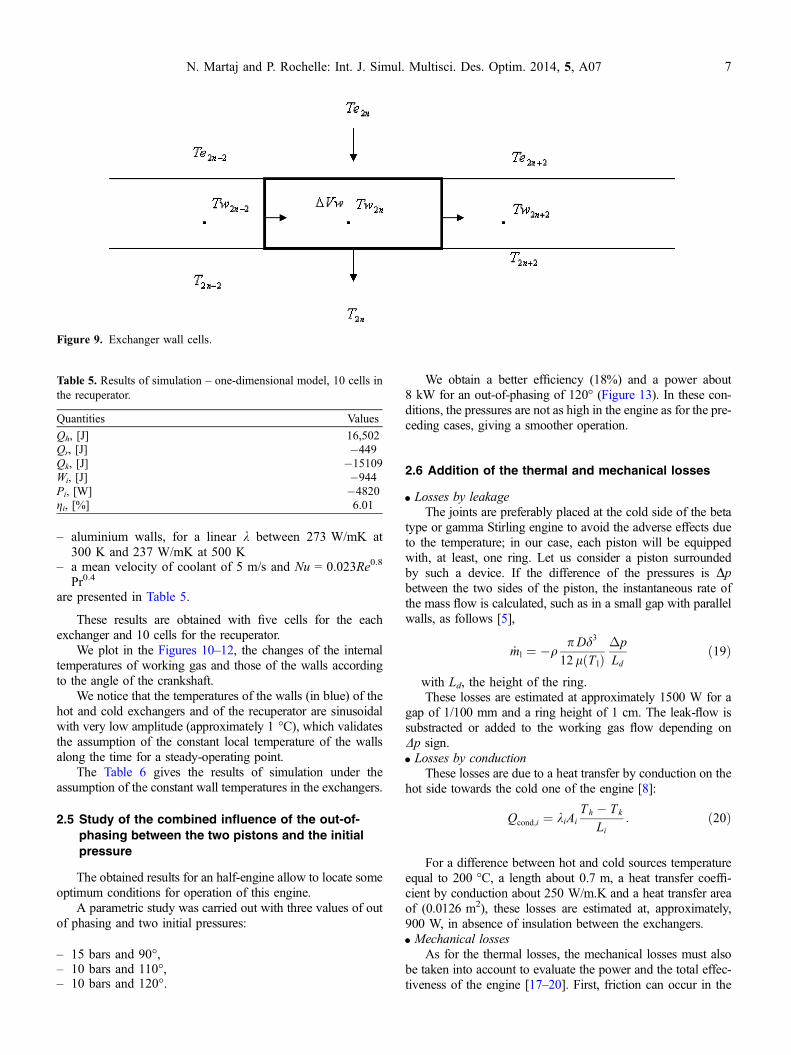
To take into account the thermal inertia of the solid walls,we establish the heat balance of an element of volume DVw(Figure 9).
The Newton’s law allows us to express the heat quantitiesexchanged by convection between the element of wall volumeand the external fluid as well as the element of wall volume andworking gas.
dQe2n ¼ � hl2nA2n Tw2n � Te2nð Þ dt; ð15Þ
dQ2n ¼ � h2n A2n Tw2n � T 2nð Þ dt: ð16Þ
The heat balance for the element of wall volume DVWallows us to determine the heat stored in the wall:
dQw2n ¼ � cpw2n qw �Vw2n dTw2n
¼ dQe2n þ dQ2n � kw2nTw2n�Tw2n�2
Lxnx
�
A2n�1 dt þ kw2nTw2nþ2 � Tw2n
Lxnx
!A2nþ1dt; ð17Þ
where LX is the length of the exchanger and nX the numberof cells per exchanger.
The wall temperature variation is given by:
dTw2n ¼ dQe2n þ dQ2n
þ kw2n �½Tw2n � Tw2n�2
Lxnx
ÞA2n�1
þ Tw2nþ2 � Tw2nLxnx
A2nþ1�dt1
cpw2n qw �Vw2n: ð18Þ
Results of simulation for:
– a speed of 300 rpm– an initial pressure of 22.7 bars
Table 4. Results of simulation – one-dimensional model, five cells inthe recuperator exchangers with smooth plates.
Quantities Values
Qh, [J] 14,168Qr, [J] �603Qk, [J] �12,836Wi, [J] �734Pi, [W] �3672gi, [%] 5.41
Figure 6. Evolution of the pressure according to the angle ofcrankshaft and to the cell number.
Figure 7. Evolution of the working gas temperature according to theangle of crankshaft and to the cell number.
Figure 8. Evolution of the gas speed according to the angle ofcrankshaft and to the cell number.
6 N. Martaj and P. Rochelle: Int. J. Simul. Multisci. Des. Optim. 2014, 5, A07
– aluminium walls, for a linear k between 273 W/mK at300 K and 237 W/mK at 500 K
– a mean velocity of coolant of 5 m/s and Nu = 0.023Re0.8
Pr0.4
are presented in Table 5.
These results are obtained with five cells for the eachexchanger and 10 cells for the recuperator.
We plot in the Figures 10–12, the changes of the internaltemperatures of working gas and those of the walls accordingto the angle of the crankshaft.
We notice that the temperatures of the walls (in blue) of thehot and cold exchangers and of the recuperator are sinusoidalwith very low amplitude (approximately 1 �C), which validatesthe assumption of the constant local temperature of the wallsalong the time for a steady-operating point.
The Table 6 gives the results of simulation under theassumption of the constant wall temperatures in the exchangers.
2.5 Study of the combined influence of the out-of-
phasing between the two pistons and the initial
pressure
The obtained results for an half-engine allow to locate someoptimum conditions for operation of this engine.
A parametric study was carried out with three values of outof phasing and two initial pressures:
– 15 bars and 90�,– 10 bars and 110�,– 10 bars and 120�.
We obtain a better efficiency (18%) and a power about8 kW for an out-of-phasing of 120� (Figure 13). In these con-ditions, the pressures are not as high in the engine as for the pre-ceding cases, giving a smoother operation.
2.6 Addition of the thermal and mechanical losses
d Losses by leakageThe joints are preferably placed at the cold side of the beta
type or gamma Stirling engine to avoid the adverse effects dueto the temperature; in our case, each piston will be equippedwith, at least, one ring. Let us consider a piston surroundedby such a device. If the difference of the pressures is Dpbetween the two sides of the piston, the instantaneous rate ofthe mass flow is calculated, such as in a small gap with parallelwalls, as follows [5],
_ml ¼ �qp Dd3
12 lðT lÞ�pLd
ð19Þ
with Ld, the height of the ring.These losses are estimated at approximately 1500 W for a
gap of 1/100 mm and a ring height of 1 cm. The leak-flow issubstracted or added to the working gas flow depending onDp sign.d Losses by conduction
These losses are due to a heat transfer by conduction on thehot side towards the cold one of the engine [8]:
Qcond;i ¼ kiAiT h � T k
Li: ð20Þ
For a difference between hot and cold sources temperatureequal to 200 �C, a length about 0.7 m, a heat transfer coeffi-cient by conduction about 250 W/m.K and a heat transfer areaof (0.0126 m2), these losses are estimated at, approximately,900 W, in absence of insulation between the exchangers.d Mechanical losses
As for the thermal losses, the mechanical losses must alsobe taken into account to evaluate the power and the total effec-tiveness of the engine [17–20]. First, friction can occur in the
Table 5. Results of simulation – one-dimensional model, 10 cells inthe recuperator.
Quantities Values
Qh, [J] 16,502Qr, [J] �449Qk, [J] �15109Wi, [J] �944Pi, [W] �4820gi, [%] 6.01
Figure 9. Exchanger wall cells.
N. Martaj and P. Rochelle: Int. J. Simul. Multisci. Des. Optim. 2014, 5, A07 7

Figure 10. Evolution of the gas and wall temperature in the hot exchanger.
Figure 11. Evolution of the gas and wall temperature in the cold exchanger.
8 N. Martaj and P. Rochelle: Int. J. Simul. Multisci. Des. Optim. 2014, 5, A07

kinematics seals/rings of the piston and the displacer as well ason the shaft. In addition, the seals of the other moving parts canlead to great forces of friction.
The calculation of frictions is carried out using the follow-ing expression:
W f ¼ pmf :V u ð21Þ
where, pmf is the average pressure of friction in bar, givenby the following equation:
pmf ¼ aþ bN
1000: ð22Þ
N: engine speed rev/mina = 0.5 constant in bar,b = 0.1 constant in (bar · 1000)/(rev/min).
These values correspond appreciably to half of those usedin the reciprocating internal combustion engines. Expressed in
term of a friction torque, the expression becomes:
Tomf ¼ af þ bf � N1000
: ð23Þ
The losses by mechanical friction for this alpha type Stirlingengine, with double-acting piston, and crankshaft-connectingrod kinematics, are estimated at 2.7 kW.
3. Conclusion
In this paper, an original model of double effect Stirlingengine was studied. Its originality lies in the exchanges in theregenerator. This is not only a model of a matrix thermal inertiawith back and forth exchanges with the same gas, as in the tra-ditional Stirling engines, but an exchanger with two parallel cir-cuits in which the exchanges are done between two gasesthrough a wall with some thermal inertia.
We studied a 1-D model, derived from the Andersen modelwith finite volumes (volumes are subdivided into cells of calcu-lation). We have introduced variable convective heat transferand flow friction coefficients. This model, using mass, momen-tum and energy balances of the compressible flows, takes intoaccount the instantaneous internal irreversibilities like the pres-sure losses in the exchangers and the thermal inertia of the wallsas well as the leakages which were taken into account in themost advanced calculus. Using this model, we can plot thespeeds, the temperatures, the pressures and the densities ofworking gas according to time, and/or angle of crankshaft,and space (1-D). We obtain the operating characteristics ofthe engine (powers, efficiencies).
Figure 12. Evolution of the gas and wall temperature in the recuperator.
Table 6. Results with constant temperatures in the exchanger walls.
Quantities Values
Qh, [J] 14,896Qr, [J] �1049Qk, [J] �12,786Wi, [J] �1067Pi, [W] �5334gi, [%] 7.7
N. Martaj and P. Rochelle: Int. J. Simul. Multisci. Des. Optim. 2014, 5, A07 9

A parametric study showed that a better efficiency (18%)for a power of approximately 8 kW was obtained for an out-of-phasing of 120�.
This 1-D model is simulated under Simulink environment(with multiple cells).
This solar power plant system is under construction and wehave not yet the experimental data at our disposal in order tocompare with simulation results. Our simulation is used to eval-uate the system behavior under several conditions and obtain itspower and thermal efficiency and deduce the ‘‘best’’configuration.
Acknowledgements. The authors gratefully acknowledge SchneiderElectric – leader of MiCST project – and all the partners of the con-sortium: Barriquand Technologies Thermiques, CEA-INES, CedratTechnologies, Defi Systemes, Exosun, LEME, LEMTA, Meca-chrome France, SAED and Stiral. The authors also gratefullyacknowledge the ADEME which greatly supports the MiCSTproject.
References
1. Andersen S. March 2006. Numerical Simulation of CyclicThermodynamic Processes, PhD thesis, Department of Mechan-ical Engineering, Technical University of Denmark.
2. Bonnet S. 2005. Moteurs Thermiques A Apport de ChaleurExterne : Etude d’un Moteur Stirling et d’un Moteur Ericsson.PhD thesis, Universite de Pau et des Pays de l’Adour.
3. Der Minassians A. December 2007. A. Stirling Engines forLow-Temperature Solar-Thermal-Electric Power Generation.PhD thesis, University of California at Berkeley.
4. Grosu L, Rochelle P. 2009. Application de la methode deSchmidt avec regeneration imparfaite aux 3 types de moteur
Stirling. Nouvelles solutions analytiques, congres SFT, Vol. 2,Vannes, 26–29 mai. p. 895–901.
5. Homutescu VM, Dumitras�cu G, Horbaniuc B. 2008. Evaluationof the work lost due to leaks through cylinder-displacer GAP,COFRET’08. Nantes, Juin.
6. Martaj N. Decembre 2008. Modelisation Energetique etexergetique, simulation et optimisation des moteurs Stirling afaible difference des temperatures – Confrontation avecl’experience, These de l’Universite Paris 10, Nanterre.
7. Stouffs P, Bonnet S, Alaphilippe M. 2002. Etude experimentaledes transferts thermiques et des transformations thermodynam-iques dans un petit moteur Stirling, in Elsevier, Actes duCongres SFT’02, Paris. p. 763–768.
8. Reader Y. 1983. Stirling Engines. E et F.N. Spon, London andNew York.
9. Urieli I, Berchowitz DM. 1984. Stirling Cycle Engine Analysis.Bristol, UK: Adam Hilger.
10. Tlili I, Timoumi Y, Ben Nasrallah S. 2007. Thermodynamicanalysis of Stirling heat engine with regenerative losses andinternal irreversibilities. International Journal of EngineResearch, 9, 45–56.
11. Andersen SK, Carlsen H, Per Grove Thomsen. 2005. Pre-liminary results from simulations of temperature oscillations inStirling engine regenerator matrices. Energy, 1–13.
12. Kongtragool B, Wongwises S. 2005. Investigation on poweroutput of the gamma configuration low temperature differentialStirling engines. Renewable Energy, 30(3), 465–476.
13. Robson A. 2005. Development of a computer model to simulate alow temperature differential RingbomStirling engine, in Thermo-and GFD Modelling of Stirling Machines, Proceedings 12thInternational Stirling Engine Conference, Durham, p. 350–357.
14. Ercan Ataera O, Karabulut H. 2005. Thermodynamic analysis ofthe V-type Stirling-cycle refrigerator. International Journal ofRefrigeration, 28, 183–189.
Figure 13. Evolution of the indicated power and the indicated efficiency versus the engine speeds for different phasing: 90�, 110� and 120�and initial pressure.
10 N. Martaj and P. Rochelle: Int. J. Simul. Multisci. Des. Optim. 2014, 5, A07

15. Feidt M, Lesaos K, Costea M, Petrescu S. 2002. Optimalallocation of HEX inventory associated with fixed power outputor fixed heat transfer rate input. International Journal of AppliedThermodynamics, 5(1), 25–36.
16. Ibrahim MB, Zhiguo Z, Rong W, Simon TW, Gedeon D. 2002.A 2-D CFD Model of Oscillatory Flow With Jets Impinging ona Random Wire Regenerator Matrix. Piscataway NJ, Etats-Unis:IEEE.
17. Wang JT, Chen J. 2002. Influence of several irreversible losseson the performance of a ferroelectric Stirling refrigeration-cycle.Applied Energy, 72, 495–511.
18. Senft JR. 1998. Theoretical limits on the performance of Stirlingengines. International Journal of Engine Research, 22, 991–1000.
19. Wu F, Chen L, Wu C, Sun F. 1998. Optimum performance ofirreversible Stirling engine with imperfect regeneration. EnergyConversion Management, 39(8), 727–732.
20. Organ AJ. 1997. The Regenerator and the Stirling Engine.Wiley, ISBN: 1-860658010-6.
Cite this article as: Martaj N & Rochelle P: 1D modelling of an alpha type Stirling engine. Int. J. Simul. Multisci. Des. Optim., 2014,5, A07.
N. Martaj and P. Rochelle: Int. J. Simul. Multisci. Des. Optim. 2014, 5, A07 11