Embed Size (px)
Citation preview
400 Commonwealth Drive, Warrendale, PA 15096-0001 U.S.A. Tel: (724) 776-4841 Fax: (724) 776-5760
SAE TECHNICALPAPER SERIES 1999-01-0965
ASPECT Manikin Applications andMeasurements for Design,Audit, and Benchmarking
Ronald W. Roe, Matthew P. Reed and Lawrence W. SchneiderUniversity of Michigan Transportation Research Institute
International Congress and ExpositionDetroit, Michigan
March 1-4, 1999
The appearance of this ISSN code at the bottom of this page indicates SAE’s consent that copies of thepaper may be made for personal or internal use of specific clients. This consent is given on the condition,however, that the copier pay a $7.00 per article copy fee through the Copyright Clearance Center, Inc.Operations Center, 222 Rosewood Drive, Danvers, MA 01923 for copying beyond that permitted by Sec-tions 107 or 108 of the U.S. Copyright Law. This consent does not extend to other kinds of copying such ascopying for general distribution, for advertising or promotional purposes, for creating new collective works,or for resale.
SAE routinely stocks printed papers for a period of three years following date of publication. Direct yourorders to SAE Customer Sales and Satisfaction Department.
Quantity reprint rates can be obtained from the Customer Sales and Satisfaction Department.
To request permission to reprint a technical paper or permission to use copyrighted SAE publications inother works, contact the SAE Publications Group.
No part of this publication may be reproduced in any form, in an electronic retrieval system or otherwise, without the prior writtenpermission of the publisher.
ISSN 0148-7191Copyright 1999 Society of Automotive Engineers, Inc.
Positions and opinions advanced in this paper are those of the author(s) and not necessarily those of SAE. The author is solelyresponsible for the content of the paper. A process is available by which discussions will be printed with the paper if it is published inSAE Transactions. For permission to publish this paper in full or in part, contact the SAE Publications Group.
Persons wishing to submit papers to be considered for presentation or publication through SAE should send the manuscript or a 300word abstract of a proposed manuscript to: Secretary, Engineering Meetings Board, SAE.
Printed in USA
All SAE papers, standards, and selectedbooks are abstracted and indexed in theGlobal Mobility Database
1
1999-01-0965
ASPECT Manikin Applications andMeasurements for Design,Audit, and Benchmarking
Ronald W. Roe, Matthew P. Reed and Lawrence W. SchneiderUniversity of Michigan Transportation Research Institute
Copyright © 1999 Society of Automotive Engineers, Inc.
ABSTRACT
The ASPECT (Automotive Seat and Package Evaluationand Comparison Tools) manikin provides new capabilitiesfor vehicle and seat measurement while maintaining con-tinuity with previous practices. This paper describes howthe manikin is used in the development of new designs,the audit verification of build, and in benchmarking com-petitive vehicles and seats. The measurement proce-dures are discussed in detail, along with the seat andpackage dimensions that are associated with the newtool.
INTRODUCTION
Procedures and tools developed by committees of theSociety of Automotive Engineers (SAE) and documentedin SAE recommended practices are used extensively dur-ing the vehicle design process (1).1 The H-point manikindescribed in SAE J826 provides the H-point, a referencepoint used to predict the location of occupants in vehi-cles. The seating reference point (SgRP) defined in SAEJ1100 locates the H-point in the vehicle workspace fordrivers and passengers. Pedal plane angle (q) and the95th-percentile selected seat position curve described inSAE J1516 and J1517 are used to position the SgRP andmanikin thigh, leg, and shoe. Additional measures pro-vided by the H-point manikin and defined in SAE J1100describe seat characteristics and the spatial relationshipsfor seated occupants (the seating package). Assessmenttools for spatial accommodation are provided by SAEJ1517 (Driver Selected Seat Position), SAE J941 (Driv-ers’ Eye Location), SAE J1052 (Driver and PassengerHead Location), and SAE J287 (Driver Hand ControlsReach).
The SAE J826 H-point manikin is used in three generalapplication categories during the development of seatingpackages. In design, the H-point and associated refer-ence points and measurement definitions are used tospecify seating package geometry for a proposed vehi-
cle. After a prototype of the design is constructed, it isaudited using the H-point manikin to determine buildaccuracy in relation to design specifications. The H-pointmanikin is also used to measure vehicles from othermanufacturers for which the design intent is not known,an application commonly called benchmarking. Audit andbenchmarking differ in that the design intent and specifi-cations are known prior to beginning an audit evaluation,while benchmarking is conducted without any previousinformation about the vehicle or seat design specifica-tions.
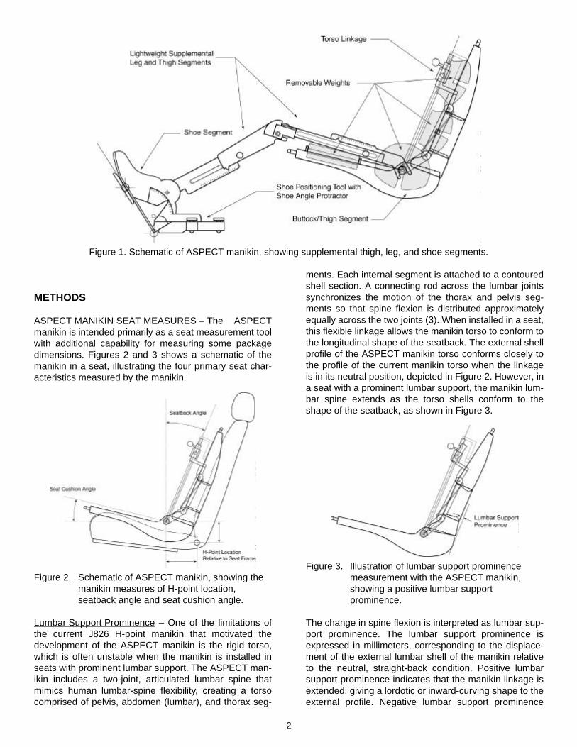
The ASPECT manikin (also called the ASPECT PhysicalManikin, or APM, to differentiate it from its CAD counter-part) provides improvements over the current H-pointmanikin in its ability to measure the postural supportcharacteristics of seats (2-5). Figure 1 shows a sche-matic of the manikin. The H-Point is retained as the pri-mary reference point, and a new articulated torsomeasures the longitudinal contour of the seatback,expressed as lumbar support prominence. The manikinalso simultaneously measures seat cushion angle andseatback angle.
Unlike the current H-point manikin, the ASPECT manikinmeasures H-point location in a seat without being con-nected to the vehicle package through leg segments. TheASPECT manikin includes supplemental thigh, leg, andshoe segments that can be used to measure the packagegeometry, but these segments are not needed for thebasic H-point measurement of the seat. This separationbetween seat and package measures simplifies use ofthe manikin and allows seats to be measured indepen-dent of the rest of the vehicle.
In this paper, proposed procedures for using theASPECT manikin in vehicle design, audit, and bench-marking are presented. The manikin procedures are inte-grated with other tools developed in the ASPECTprogram, as well as with new accommodation modelsdeveloped in coordination with ASPECT (5). These pro-cedures and tools may be revised as they are consideredfor incorporation into SAE recommended practices. Theproposed procedures are intended to facilitate discussionand evaluation of the new tools.1. Numbers in parentheses denote references at the end of
the paper.
2
Figure 1. Schematic of ASPECT manikin, showing supplemental thigh, leg, and shoe segments.
METHODS
ASPECT MANIKIN SEAT MEASURES – The ASPECTmanikin is intended primarily as a seat measurement toolwith additional capability for measuring some packagedimensions. Figures 2 and 3 shows a schematic of themanikin in a seat, illustrating the four primary seat char-acteristics measured by the manikin.
Figure 2. Schematic of ASPECT manikin, showing the manikin measures of H-point location, seatback angle and seat cushion angle.
Lumbar Support Prominence – One of the limitations ofthe current J826 H-point manikin that motivated thedevelopment of the ASPECT manikin is the rigid torso,which is often unstable when the manikin is installed inseats with prominent lumbar support. The ASPECT man-ikin includes a two-joint, articulated lumbar spine thatmimics human lumbar-spine flexibility, creating a torsocomprised of pelvis, abdomen (lumbar), and thorax seg-
ments. Each internal segment is attached to a contouredshell section. A connecting rod across the lumbar jointssynchronizes the motion of the thorax and pelvis seg-ments so that spine flexion is distributed approximatelyequally across the two joints (3). When installed in a seat,this flexible linkage allows the manikin torso to conform tothe longitudinal shape of the seatback. The external shellprofile of the ASPECT manikin torso conforms closely tothe profile of the current manikin torso when the linkageis in its neutral position, depicted in Figure 2. However, ina seat with a prominent lumbar support, the manikin lum-bar spine extends as the torso shells conform to theshape of the seatback, as shown in Figure 3.
Figure 3. Illustration of lumbar support prominence measurement with the ASPECT manikin, showing a positive lumbar support prominence.
The change in spine flexion is interpreted as lumbar sup-port prominence. The lumbar support prominence isexpressed in millimeters, corresponding to the displace-ment of the external lumbar shell of the manikin relativeto the neutral, straight-back condition. Positive lumbarsupport prominence indicates that the manikin linkage isextended, giving a lordotic or inward-curving shape to theexternal profile. Negative lumbar support prominence
3
indicates an outward-curving or kyphotic external profile,and the lumbar prominence reading is zero when theseat produces a manikin profile that corresponds to theflat profile of the current SAE J826 manikin.
Seatback Angle – The ASPECT manikin includes a torsoline that replicates the function of the torso line on thecurrent J826 manikin and two-dimensional (2D) templatefor defining and measuring seatback angle. The ASPECTmanikin torso line is parallel to the surface profile in thelumbar area of the manikin when installed in a seat withzero lumbar support prominence, just as the torso line ofthe current manikin is parallel to the external shell profile.For other levels of lumbar support prominence, the torsoline remains approximately parallel to the external shellsection connected to the lumbar segment of the manikin.Note that the manikin torso line does not connect the H-point with another point having an anatomical correlate,such as the shoulder. When installed in a seat, the angleof the ASPECT manikin torso line with respect to verticaldefines the seatback angle. Combined with the lumbarsupport prominence measure, seatback angle measuresthe deflected surface contour of the seatback in a waythat can be related to human posture.
Seat Cushion Angle – SAE J826 was recently amendedto include a technique for measuring seat cushion angle.In the J826 procedure, the current manikin is installedwithout legs and with a modified weight distribution toobtain a measure of the orientation of the deflected seatcushion surface. This measure is a factor affecting driver-selected seat position and driver posture (6, 7). TheASPECT manikin produces a similar measure as part ofthe normal installation process. A thigh line is defined onthe manikin at an orientation designed to replicate theseat cushion angle measure obtained with the J826 man-ikin. This is approximately the orientation of a line con-
necting the hip and knee joints of a midsize male sittingwith his thighs fully engaged with the seat cushion. Thethigh orientations of sitters will usually differ from themeasured seat cushion angle because thigh angle isaffected by factors other than seat cushion angle, suchas seat height.
H-Point Location – The distances from the ASPECTmanikin H-point to the bottom and rear of the manikinbuttock/thigh shell profile are designed to be the same asthe corresponding dimensions on the current J826 mani-kin. As with the current manikin, the H-point is intendedto approximate the hip joint location of a human in theseat. When the ASPECT manikin is installed in a seatwith a lumbar support prominence that measures zero,the ASPECT manikin H-point is intended to be coincidentwith the SAE J826 H-point (3). However, in seats withmore- or less-prominent lumbar supports, differencesbetween the manikins in H-point location are expected.The H-point location will not generally replicate the hipjoint location of any particular category of sitter. Hip jointlocations are affected by a number of factors, only someof which are measured by the manikin. The manikin H-point is one of the inputs to posture prediction modelsthat are used to locate human hip joints relative to thevehicle and seat (4).
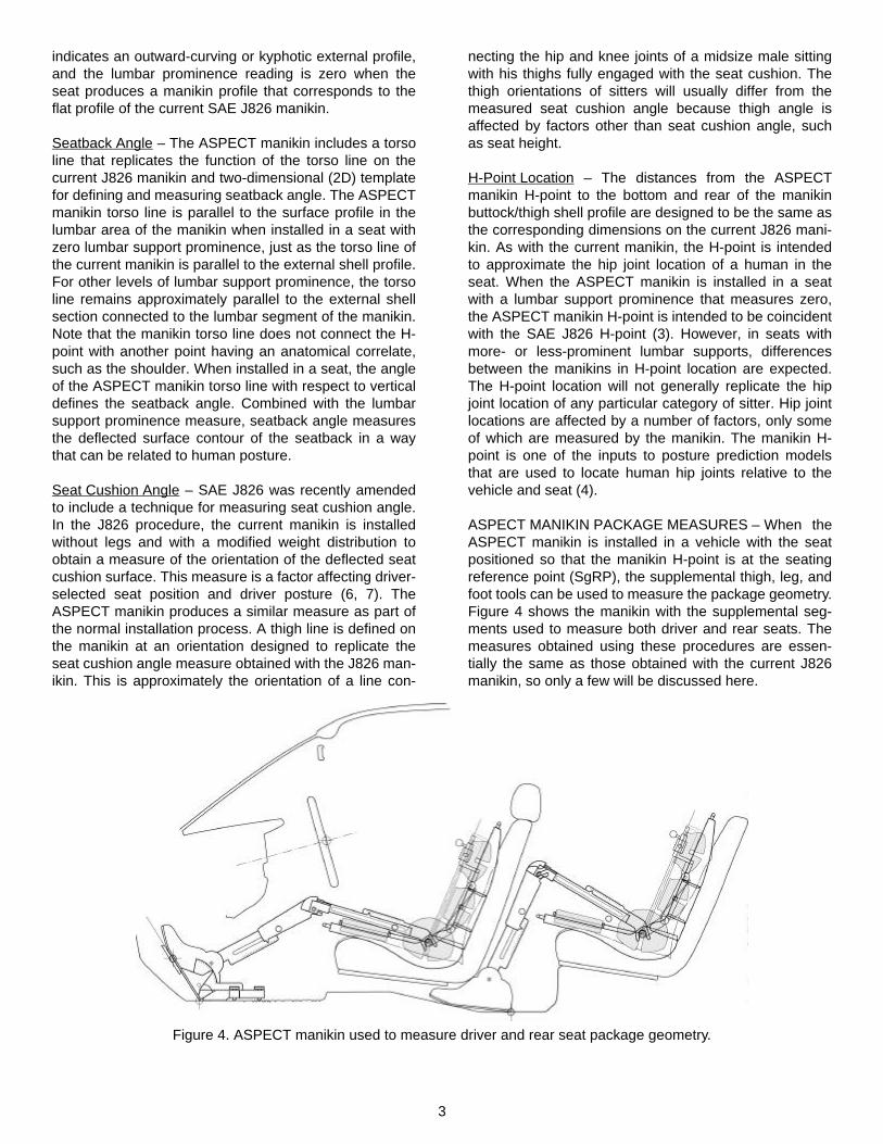
ASPECT MANIKIN PACKAGE MEASURES – When theASPECT manikin is installed in a vehicle with the seatpositioned so that the manikin H-point is at the seatingreference point (SgRP), the supplemental thigh, leg, andfoot tools can be used to measure the package geometry.Figure 4 shows the manikin with the supplemental seg-ments used to measure both driver and rear seats. Themeasures obtained using these procedures are essen-tially the same as those obtained with the current J826manikin, so only a few will be discussed here.
Figure 4. ASPECT manikin used to measure driver and rear seat package geometry.
4
Thigh Angle – The vertical distance from the SgRP to theheel rest surface, denoted H30 in SAE J1100 for thedriver seat, is the seat height. Because the ASPECTmanikin thigh segment is independent of the weightedmanikin buttock/thigh shell, the manikin measures a thighangle (relative to horizontal) that is generally greater thanthe seat cushion angle. The thigh angle is determined bythe package geometry, specifically the seat height. Infact, using the practices described in this paper for locat-ing the pedal reference point, shoe angle, and SgRP,thigh angle can be calculated directly from seat height.
Knee Angle – Knee angle is the included angle betweenthe thigh and leg segments, and is essentially identical tothe measure denoted L44 in SAE J1100. The angle ismeasured in a vertical plane only. Because the kneeangle is measured with the seat located at the SgRP andwith defined leg and thigh segment lengths, it does notnecessarily represent the knee angles of any particularoccupants.
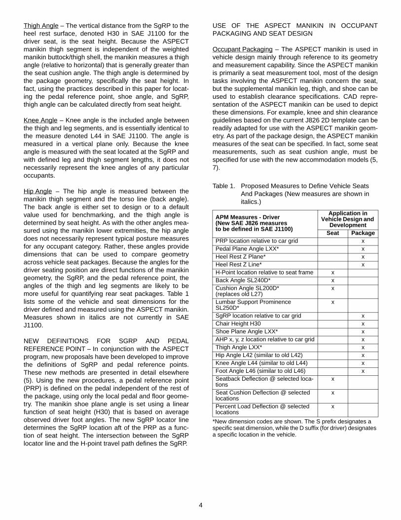
Hip Angle – The hip angle is measured between themanikin thigh segment and the torso line (back angle).The back angle is either set to design or to a defaultvalue used for benchmarking, and the thigh angle isdetermined by seat height. As with the other angles mea-sured using the manikin lower extremities, the hip angledoes not necessarily represent typical posture measuresfor any occupant category. Rather, these angles providedimensions that can be used to compare geometryacross vehicle seat packages. Because the angles for thedriver seating position are direct functions of the manikingeometry, the SgRP, and the pedal reference point, theangles of the thigh and leg segments are likely to bemore useful for quantifying rear seat packages. Table 1lists some of the vehicle and seat dimensions for thedriver defined and measured using the ASPECT manikin.Measures shown in italics are not currently in SAEJ1100.
NEW DEFINITIONS FOR SGRP AND PEDALREFERENCE POINT – In conjunction with the ASPECTprogram, new proposals have been developed to improvethe definitions of SgRP and pedal reference points.These new methods are presented in detail elsewhere(5). Using the new procedures, a pedal reference point(PRP) is defined on the pedal independent of the rest ofthe package, using only the local pedal and floor geome-try. The manikin shoe plane angle is set using a linearfunction of seat height (H30) that is based on averageobserved driver foot angles. The new SgRP locator linedetermines the SgRP location aft of the PRP as a func-tion of seat height. The intersection between the SgRPlocator line and the H-point travel path defines the SgRP.
USE OF THE ASPECT MANIKIN IN OCCUPANTPACKAGING AND SEAT DESIGN
Occupant Packaging – The ASPECT manikin is used invehicle design mainly through reference to its geometryand measurement capability. Since the ASPECT manikinis primarily a seat measurement tool, most of the designtasks involving the ASPECT manikin concern the seat,but the supplemental manikin leg, thigh, and shoe can beused to establish clearance specifications. CAD repre-sentation of the ASPECT manikin can be used to depictthese dimensions. For example, knee and shin clearanceguidelines based on the current J826 2D template can bereadily adapted for use with the ASPECT manikin geom-etry. As part of the package design, the ASPECT manikinmeasures of the seat can be specified. In fact, some seatmeasurements, such as seat cushion angle, must bespecified for use with the new accommodation models (5,7).
Table 1. Proposed Measures to Define Vehicle Seats And Packages (New measures are shown in italics.)
APM Measures - Driver (New SAE J826 measures to be defined in SAE J1100)
Application inVehicle Design and
DevelopmentSeat Package
PRP location relative to car grid xPedal Plane Angle LXX* xHeel Rest Z Plane* xHeel Rest Z Line* xH-Point location relative to seat frame xBack Angle SL240D* xCushion Angle SL200D* (replaces old L27)
x
Lumbar Support Prominence SL250D*
x
SgRP location relative to car grid xChair Height H30 xShoe Plane Angle LXX* xAHP x, y, z location relative to car grid xThigh Angle LXX* xHip Angle L42 (similar to old L42) xKnee Angle L44 (similar to old L44) xFoot Angle L46 (similar to old L46) xSeatback Deflection @ selected loca-tions
x
Seat Cushion Deflection @ selected locations
x
Percent Load Deflection @ selected locations
x
*New dimension codes are shown. The S prefix designates a specific seat dimension, while the D suffix (for driver) designates a specific location in the vehicle.
5
Seat Design – Each of the measurements that can bemade with the manikin corresponds to a potential specifi-cation for seat design. The H-point location relative to theseat frame is specified, as are the seat cushion angleand lumbar support prominence. A particular manikin-measured (seat) back angle is selected to correspond toa particular seatback frame orientation. In addition, themanikin H-point, torso line, and thigh line can be used asreferences to define many additional seat measures.Appendix D describes a large number of proposed seatdimensions, many of which are referenced to theASPECT manikin.
USE OF THE ASPECT MANIKIN FOR AUDIT ANDBENCHMARKING – The primary use of the ASPECTmanikin is measuring vehicle seats and packages. Themeasurement is considered an audit if the primary pur-pose is to assess the extent to which a seat or vehiclemeets with design intent. In an audit measurement, thedesign positions of the vehicle and seat components tobe used during the measurement have been previouslyspecified by the vehicle manufacturer. Benchmarkingwith the ASPECT manikin uses very similar proceduresto measure a vehicle for which the design intent is notknown. Consequently, the positions and settings of vehi-cle components and adjustments must be determinedusing standardized guidelines to ensure compatibility ofthe measurements across vehicles. To simplify the pre-sentation, the audit procedures will be described first, fol-lowed by the changes to the procedures necessary for abenchmarking measurement.
Seat Measurement – A seat measurement begins by set-ting the seat components to the designated configuration.The seat cushion frame angle and seatback frame angleare set to the design position, meaning the default valuesset by the vehicle designer. Any other adjustments, suchas lateral bolsters or adjustable lumbar supports, are setto their design positions. In effect, the seat componentsare placed in the positions and orientations that areexpected to produce particular manikin measurements.The audit determines if the seat build has met the intent.
The manikin is then installed in the seat, using the proce-dure in Appendix A. A muslin cloth identical to the onecurrently specified in J826 is laid on the seat to standard-ize the friction under the manikin. The manikin is placedon the seat and the torso linkage is unlocked to allow thetorso to conform to the shape of the seatback. If desired,the manikin buttock/thigh segment can be placed on theseat first, followed by the torso, which connects to thebuttock/thigh segment at the H-point. Weights are addedto the buttock/thigh pan first, then to the torso. After eachloading step, calibrated springs are used to push themanikin into the seat and built-in levels are used toensure that the manikin is aligned with the seat. After allof the weights have been added, the torso linkage islocked to prevent movement during measurement, com-
pleting the installation. The locations of reference pointson the manikin can be recorded using coordinate mea-surement equipment, and the seat cushion angle, backangle, and lumbar support prominence can be read fromscales on the manikin or by using inclinometers placedon specified manikin measurement surfaces.
Package Measurement – For package measurement, themanikin is used with the supplemental thigh, leg, andshoe segments. Because these segments do not interactdynamically with the vehicle or seat, most of the packagemeasurements can be performed in CAD after measuringthe seat with the manikin and recording the locations of afew points on the accelerator pedal and floor. However,the entire procedure can also be conducted physically, ina vehicle or mockup. Appendix C describes the entireprocedure using parallel steps for physical and CADmeasurement.
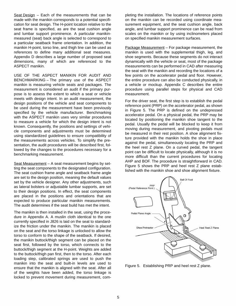
For the driver seat, the first step is to establish the pedalreference point (PRP) on the accelerator pedal, as shownin Figure 5. The PRP is defined on the undepressedaccelerator pedal. On a physical pedal, the PRP may belocated by positioning the manikin shoe tangent to thepedal. Usually the pedal will be blocked to keep it frommoving during measurement, and pivoting pedals mustbe measured in their rest position. A shoe alignment fix-ture provided with the manikin holds the shoe in placeagainst the pedal, simultaneously locating the PRP andthe heel rest Z plane. On a curved pedal, the tangentpoint can be difficult to locate physically, although it is nomore difficult than the current procedures for locatingAHP and BOF. The procedure is straightforward in CAD.Figure 5 shows the PRP and heel rest Z plane estab-lished with the manikin shoe and shoe alignment fixture.
Figure 5. Establishing PRP and heel rest Z plane.
6
Next, the ASPECT manikin is installed in the seat, follow-ing the procedures described above and in Appendix A.The seat may be positioned anywhere within its tracktravel range, provided that the seat cushion and seatbackhave the appropriate orientations with respect to vertical.For an audit measurement, the seat track, seatbackrecliner, and any other seat adjustments would be placedin their design positions. Seat position will typically bespecified with regard to seat track position, such as threedetents forward of full rear. Alternatively, the positions ofsome fiducial points on the seat frame could be specifiedwith respect to other reference points on the vehicle. Foran audit measurement, this detailed information is com-monly provided.
The SgRP position above the heel rest Z plane definesH30, the seat height. H30 is input to the shoe angleequation to determine the appropriate shoe plane angle,and a protractor is used with the shoe alignment fixture toorient the shoe appropriately. Contact is maintainedbetween the shoe and accelerator pedal, but the contactpoint need not be the PRP.
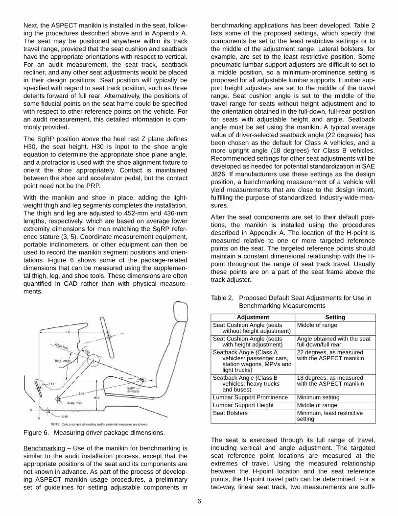
With the manikin and shoe in place, adding the light-weight thigh and leg segments completes the installation.The thigh and leg are adjusted to 452-mm and 436-mmlengths, respectively, which are based on average lowerextremity dimensions for men matching the SgRP refer-ence stature (3, 5). Coordinate measurement equipment,portable inclinometers, or other equipment can then beused to record the manikin segment positions and orien-tations. Figure 6 shows some of the package-relateddimensions that can be measured using the supplemen-tal thigh, leg, and shoe tools. These dimensions are oftenquantified in CAD rather than with physical measure-ments.
Figure 6. Measuring driver package dimensions.
Benchmarking – Use of the manikin for benchmarking issimilar to the audit installation process, except that theappropriate positions of the seat and its components arenot known in advance. As part of the process of develop-ing ASPECT manikin usage procedures, a preliminaryset of guidelines for setting adjustable components in
benchmarking applications has been developed. Table 2lists some of the proposed settings, which specify thatcomponents be set to the least restrictive settings or tothe middle of the adjustment range. Lateral bolsters, forexample, are set to the least restrictive position. Somepneumatic lumbar support adjusters are difficult to set toa middle position, so a minimum-prominence setting isproposed for all adjustable lumbar supports. Lumbar sup-port height adjusters are set to the middle of the travelrange. Seat cushion angle is set to the middle of thetravel range for seats without height adjustment and tothe orientation obtained in the full-down, full-rear positionfor seats with adjustable height and angle. Seatbackangle must be set using the manikin. A typical averagevalue of driver-selected seatback angle (22 degrees) hasbeen chosen as the default for Class A vehicles, and amore upright angle (18 degrees) for Class B vehicles.Recommended settings for other seat adjustments will bedeveloped as needed for potential standardization in SAEJ826. If manufacturers use these settings as the designposition, a benchmarking measurement of a vehicle willyield measurements that are close to the design intent,fulfilling the purpose of standardized, industry-wide mea-sures.
After the seat components are set to their default posi-tions, the manikin is installed using the proceduresdescribed in Appendix A. The location of the H-point ismeasured relative to one or more targeted referencepoints on the seat. The targeted reference points shouldmaintain a constant dimensional relationship with the H-point throughout the range of seat track travel. Usuallythese points are on a part of the seat frame above thetrack adjuster.
The seat is exercised through its full range of travel,including vertical and angle adjustment. The targetedseat reference point locations are measured at theextremes of travel. Using the measured relationshipbetween the H-point location and the seat referencepoints, the H-point travel path can be determined. For atwo-way, linear seat track, two measurements are suffi-
Table 2. Proposed Default Seat Adjustments for Use in Benchmarking Measurements
Adjustment SettingSeat Cushion Angle (seats
without height adjustment)Middle of range
Seat Cushion Angle (seats with height adjustment)
Angle obtained with the seat full down/full rear
Seatback Angle (Class Avehicles: passenger cars, station wagons, MPVs and light trucks)
22 degrees, as measured with the ASPECT manikin
Seatback Angle (Class Bvehicles: heavy trucksand buses)
18 degrees, as measured with the ASPECT manikin
Lumbar Support Prominence Minimum settingLumbar Support Height Middle of rangeSeat Bolsters Minimum, least restrictive
setting
7
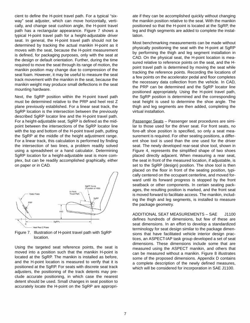
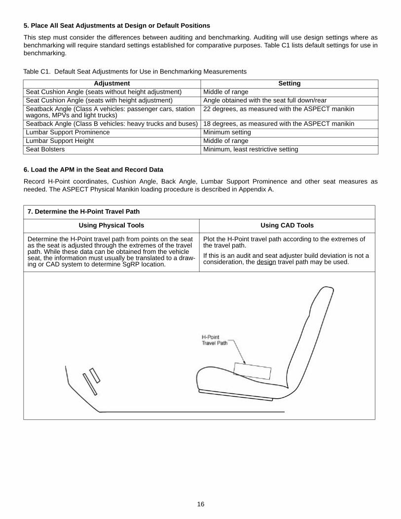
cient to define the H-point travel path. For a typical “six-way” seat adjuster, which can move horizontally, verti-cally, and change seat cushion angle, the H-point travelpath has a rectangular appearance. Figure 7 shows atypical H-point travel path for a height-adjustable driverseat. In general, the H-point travel path should not bedetermined by tracking the actual manikin H-point as itmoves with the seat, because the H-point measurementis defined, for packaging purposes, only with the seat atthe design or default orientation. Further, during the timerequired to move the seat through its range of motion, themanikin position may change due to compression of theseat foam. However, it may be useful to measure the seattrack movement with the manikin in the seat, because themanikin weight may produce small deflections in the seatmounting hardware.
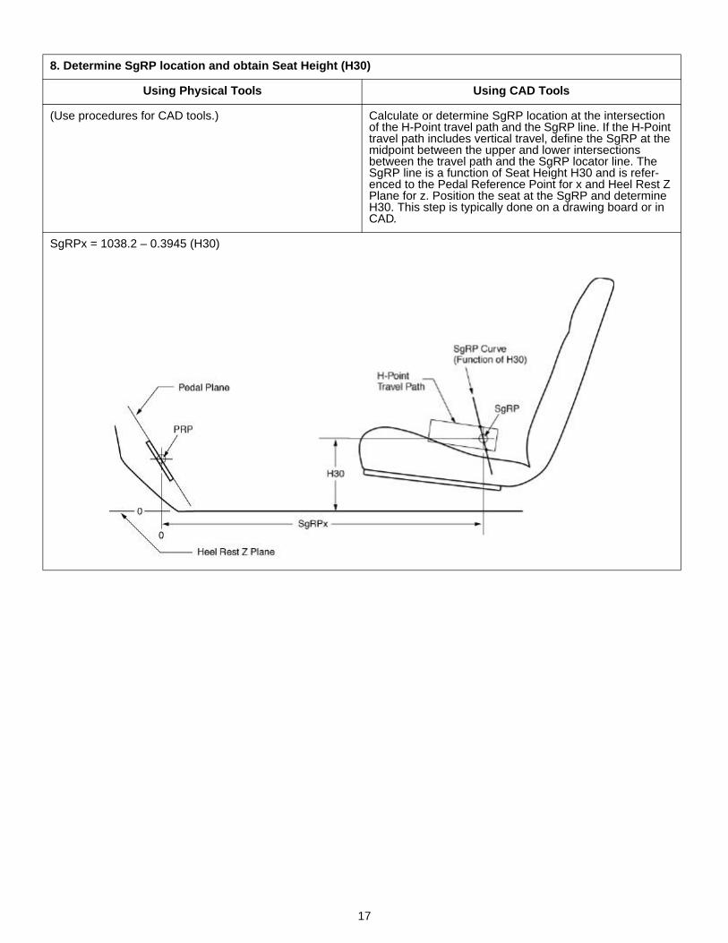
Next, the SgRP position within the H-point travel pathmust be determined relative to the PRP and heel rest Zplane previously established. For a linear seat track, theSgRP location is the intersection between the previouslydescribed SgRP locator line and the H-point travel path.For a height-adjustable seat, SgRP is defined as the mid-point between the intersections of the SgRP locator linewith the top and bottom of the H-point travel path, puttingthe SgRP at the middle of the height adjustment range.For a linear track, this calculation is performed by findingthe intersection of two lines, a problem readily solvedusing a spreadsheet or a hand calculator. DeterminingSgRP location for a height-adjustable seat is more com-plex, but can be readily accomplished graphically, eitheron paper or in CAD.
Figure 7. Illustration of H-point travel path with SgRP location.
Using the targeted seat reference points, the seat ismoved into a position such that the manikin H-point islocated at the SgRP. The manikin is installed as before,and the H-point location is measured to verify that it ispositioned at the SgRP. For seats with discrete seat trackadjusters, the positioning of the track detents may pre-clude accurate positioning, in which case the nearestdetent should be used. Small changes in seat position toaccurately locate the H-point on the SgRP are appropri-
ate if they can be accomplished quickly without changingthe manikin position relative to the seat. With the manikinpositioned so that the H-point is located at the SgRP, theleg and thigh segments are added to complete the instal-lation.
Most benchmarking measurements can be made withoutphysically positioning the seat with the H-point at SgRPby performing the thigh and leg segment installation inCAD. On the physical seat, the H-point location is mea-sured relative to reference points on the seat, and the H-point travel path is determined by moving the seat whiletracking the reference points. Recording the locations ofa few points on the accelerator pedal and floor completesthe necessary data collection from the vehicle. In CAD,the PRP can be determined and the SgRP locator linepositioned appropriately. Using the H-point travel path,the SgRP position is determined and the correspondingseat height is used to determine the shoe angle. Thethigh and leg segments are then added, completing thevirtual installation.
Passenger Seats – Passenger seat procedures are simi-lar to those used for the driver seat. For front seats, nofore-aft shoe position is specified, so only a seat mea-surement is required. For other seating positions, a differ-ent shoe tool is used than the one used for the driverseat. The newly developed rear-seat shoe tool, shown inFigure 4, represents the simplified shape of two shoesplaced directly adjacent. When measuring a rear seat,the seat in front of the measured location, if adjustable, isset to the SgRP (design) position. The shoe tool is thenplaced on the floor in front of the seating position, typi-cally centered on the occupant centerline, and moved for-ward until its forward progress is stopped by the frontseatback or other components. In certain seating pack-ages, the resulting position is marked, and the front seatis moved forward to facilitate access. The manikin, includ-ing the thigh and leg segments, is installed to measurethe package geometry.
ADDITIONAL SEAT MEASUREMENTS – SAE J1100defines hundreds of dimensions, but few of these areseat dimensions. In an effort to develop a standardizedterminology for seat design similar to the package dimen-sions that have facilitated vehicle interior design prac-tices, an ASPECT-IAP task group developed a set of seatdimensions. These dimensions include some that aremeasured using the ASPECT manikin, and others thatcan be measured without a manikin. Figure 8 illustratessome of the proposed dimensions. Appendix D containsa complete description of the newly defined measures,which will be considered for incorporation in SAE J1100.

8
Figure 8. Some proposed seat dimensions based on ASPECT manikin geometry (see Appendix D).
The ASPECT manikin can also be used to obtain mea-sures of seat stiffness that may be more closely related tothe experience of the vehicle occupant than measuresobtained using conventional techniques. The ASPECTmanikin weights are designed to be installed incremen-tally. For example, the twelve weights in the buttock/thighshell can be installed in three equal distributions of fourweights. If the H-point and thigh reference point locationsare measured at each step in the process, curves can beplotted showing the deflection of these points as a func-tion of the fractional manikin load. The slopes of thesecurves provide measures of local seat cushion stiffnessand can be used to compare and specify these proper-ties of seats. Similar seat stiffness measures can beobtained on the seatback, where the change in the lum-bar support prominence reading during loading is a use-ful measure of the stiffness of the lumbar support. Thesedeflection measurements are currently being evaluatedalong with other manikin procedures.
DISCUSSION
The ASPECT manikin was developed as an improvementon the current SAE J826 H-point manikin, preservingmany of the important performance features while provid-ing improved ease of use and additional measurementcapability. The ASPECT manikin is integrated into a newset of vehicle design and evaluation practices that includenew pedal reference points and a standardized SgRPlocation (3, 5). The installation and usage proceduresdescribed in this paper represent an evolution of the cur-rent design practice incorporating the additional function-ality of the new tools. The new manikin was produced inthe context of a research program that substantiallyexpanded the available information concerning the influ-ence of vehicle, seat, and anthropometric factors onoccupant posture. Drawing on these research results, thenew measures obtained with the manikin can be used torepresent human occupants more accurately during the
design process. The use of the manikin in design is facili-tated by related CAD tools, including occupant posture-prediction models and three-dimensional human bodyreference forms (5).
During the course of the ASPECT program, the researchteam examined a number of applications for which thecurrent J826 manikin is used that go beyond its basic rolein defining vehicle and seat reference points. Theseinclude modified procedures, such as the techniquesused in crash dummy positioning (9), and the use of themanikin with add-on devices, such as the Head RestraintMeasuring Device (10) and the Belt Fit Test Device (11).These techniques use the J826 manikin as a surrogatefor human positioning information and as a platform formounting measuring tools. Because the new ASPECTmanikin performance in vehicle seats is different fromthat of the current manikin, the current add-on tools, suchas the head-restraint and belt-fit measuring devices, can-not be used directly with the ASPECT manikin. However,the extensive vehicle occupant posture data collectedduring the ASPECT program can be used to develop sim-ilar tools to perform these measurements using theASPECT manikin, with potentially greater accuracy andease of use (4, 5, 8).
The procedures described in this paper are proposalsbased on currently available information. Additional eval-uations of the manikin and procedures are underway atthe companies participating in the ASPECT program.After modifications to the manikin and procedures aremade in response to industry evaluations, the SAEDesign Devices Committee will consider the manikin forincorporation into SAE J826 and new measurement defi-nitions for SAE J1100.
ACKNOWLEDGEMENTS
The definitions and procedures described in this paperwere assembled as part of the ASPECT program and theAAMA-funded accommodation model development.ASPECT participants are BMW, DaimlerChrysler, Ford,General Motors, Johnson Controls, Lear Corporation,Magna, PSA-Peugeot-Citroen, Toyota, Volkswagen ofAmerica, and Toyota. The authors would like to thank therepresentatives from each of these companies who par-ticipated in the program. Particular thanks go to membersof two subcommittee task groups: the IAP Seat Dimen-sions Task Group and the IAP/SAE Pedal ReferencePoint Task Group. The IAP Seat Dimensions Task Group,chaired by Mari Milosic (Magna), includes ShaneGoodhall and Gary Rupp (Ford), John Sadek (Magna),Kuntal Thakurta (Johnson Controls), Marilyn Vala (LearCorporation), and Ronald Roe (UMTRI). The IAP/SAEPedal Reference Point Task Group, chaired by RonaldRoe (UMTRI), includes Igor Gronowitz, Howard Estes,Ken Socks and John Brzustowicz (DaimlerChrysler),Gary Rupp and Manfred Heck (Ford), Dave Benedict(Toyota), and Debra Senytka (GM).

9
REFERENCES
1. Society of Automotive Engineers (1998) Automotive Engi-neering Handbook. Warrendale, PA: Society of Engineers,Inc.
2. Schneider, L.W., Reed, M.P., Roe, R.W., Manary, M.A.,Hubbard, R.P., and Flannagan, C.A.C.(1999). ASPECT:The next-generation H-point machine and related vehicleand seat design and measurement tools. Technical Paper990962. Warrendale, PA: Society of Automotive Engineers,Inc.
3. Reed, M.P., Roe, R.W., and Schneider, L.W. (1999). Designand development of the ASPECT manikin. Technical Paper990963. Warrendale, PA: Society of Automotive Engineers,Inc.
4. Reed, M.P., Manary, M.A., and Schneider, L.W. (1999).Automobile occupant posture prediction for use with humanmodels. Technical Paper 990966. Warrendale, PA: Societyof Automotive Engineers, Inc.
5. Reed, M. P.,Roe R. W., Manary, M. A., Flannagan, C.A.C.,and Schneider, L. W., (1999). New concepts in vehicle inte-rior design using ASPECT. Technical Paper 990967. War-rendale, PA; Society of Automotive Engineers, Inc.
6. Flannagan, C.C., Schneider, L.W., and Manary, M.A.(1996). Development of a seating accommodation model.Technical Paper 960479. Warrendale, PA: Society of Auto-motive Engineers, Inc.
7. Flannagan, C.A.C., Manary, M.A., Schneider, L.W., andReed, M.P. (1998). An improved seating accommodationmodel with applications to different user populations. Tech-nical Paper No. 980651. Warrendale, PA: Society of Auto-motive Engineers, Inc
8. Manary, M.A., Flannagan, C.A.C., Reed, M.P., andSchneider, L.W. (1999). Human subject testing in supportof ASPECT. Technical Paper 990960. Warrendale, PA:Society of Automotive Engineers, Inc.
9. National Highway Traffic Safety Administration (1993). Lab-oratory Procedure for FMVSS 208: Occupant Crash Pro-tection, TP-208-09. Washington DC.: U.S. Department ofTransportation, National Highway Traffic Safety Administra-tion.
10. Pedder, J. and Gane, J. (1995). Evaluation of head restraintposition in passenger vehicles in Canada. In Proc. Cana-dian Multidisciplinary Road Safety Conference IX, pp. 371-385. Quebec, Canada: Montreal University TransportationResearch Center.
11. Newman, J. A., Woods, D. K., Garland, L. A., and VanHumbeck, T. C. (1984). Development of a belt configurationtest device. Technical Paper 840402. Warrendale, PA:Society of Automotive Engineers, Inc.
10
APPENDIX A
MANIKIN INSTALLATION PROCEDURE
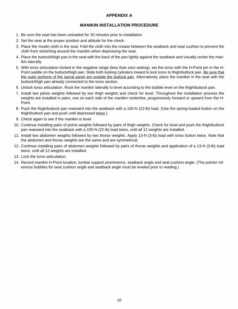
1. Be sure the seat has been unloaded for 30 minutes prior to installation.
2. Set the seat at the proper position and attitude for the check.
3. Place the muslin cloth in the seat. Fold the cloth into the crease between the seatback and seat cushion to prevent thecloth from stretching around the manikin when depressing the seat.
4. Place the buttock/thigh pan in the seat with the back of the pan lightly against the seatback and visually center the man-ikin laterally.
5. With torso articulation locked in the negative range (less than zero setting), set the torso with the H-Point pin in the H-Point saddle on the buttock/thigh pan. Slide both locking cylinders inward to lock torso to thigh/buttock pan. Be sure thatthe outer portions of the sacral panel are outside the buttock pan. Alternatively, place the manikin in the seat with thebuttock/thigh pan already connected to the torso section.
6. Unlock torso articulation. Rock the manikin laterally to level according to the bubble level on the thigh/buttock pan.
7. Install two pelvis weights followed by two thigh weights and check for level. Throughout the installation process theweights are installed in pairs, one on each side of the manikin centerline, progressively forward or upward from the H-Point.
8. Push the thigh/buttock pan rearward into the seatback with a 100-N (22-lb) load. (Use the spring-loaded button on thethigh/buttock pan and push until depressed twice.)
9. Check again to see if the manikin is level.
10. Continue installing pairs of pelvis weights followed by pairs of thigh weights. Check for level and push the thigh/buttockpan rearward into the seatback with a 100-N (22-lb) load twice, until all 12 weights are installed.
11. Install two abdomen weights followed by two thorax weights. Apply 13-N (3-lb) load with torso button twice. Note thatthe abdomen and thorax weights are the same and are symmetrical.
12. Continue installing pairs of abdomen weights followed by pairs of thorax weights and application of a 13-N (3-lb) loadtwice, until all 12 weights are installed.
13. Lock the torso articulation.
14. Record manikin H-Point location, lumbar support prominence, seatback angle and seat cushion angle. (The pointer ref-erence bubbles for seat cushion angle and seatback angle must be leveled prior to reading.)
11
APPENDIX B
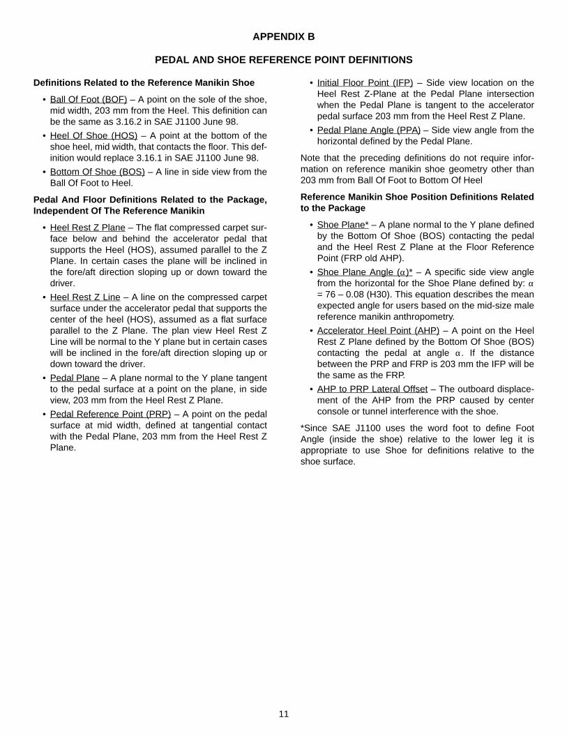
PEDAL AND SHOE REFERENCE POINT DEFINITIONS
Definitions Related to the Reference Manikin Shoe
• Ball Of Foot (BOF) – A point on the sole of the shoe,mid width, 203 mm from the Heel. This definition canbe the same as 3.16.2 in SAE J1100 June 98.
• Heel Of Shoe (HOS) – A point at the bottom of theshoe heel, mid width, that contacts the floor. This def-inition would replace 3.16.1 in SAE J1100 June 98.
• Bottom Of Shoe (BOS) – A line in side view from theBall Of Foot to Heel.
Pedal And Floor Definitions Related to the Package,Independent Of The Reference Manikin
• Heel Rest Z Plane – The flat compressed carpet sur-face below and behind the accelerator pedal thatsupports the Heel (HOS), assumed parallel to the ZPlane. In certain cases the plane will be inclined inthe fore/aft direction sloping up or down toward thedriver.
• Heel Rest Z Line – A line on the compressed carpetsurface under the accelerator pedal that supports thecenter of the heel (HOS), assumed as a flat surfaceparallel to the Z Plane. The plan view Heel Rest ZLine will be normal to the Y plane but in certain caseswill be inclined in the fore/aft direction sloping up ordown toward the driver.
• Pedal Plane – A plane normal to the Y plane tangentto the pedal surface at a point on the plane, in sideview, 203 mm from the Heel Rest Z Plane.
• Pedal Reference Point (PRP) – A point on the pedalsurface at mid width, defined at tangential contactwith the Pedal Plane, 203 mm from the Heel Rest ZPlane.
• Initial Floor Point (IFP) – Side view location on theHeel Rest Z-Plane at the Pedal Plane intersectionwhen the Pedal Plane is tangent to the acceleratorpedal surface 203 mm from the Heel Rest Z Plane.
• Pedal Plane Angle (PPA) – Side view angle from thehorizontal defined by the Pedal Plane.
Note that the preceding definitions do not require infor-mation on reference manikin shoe geometry other than203 mm from Ball Of Foot to Bottom Of Heel
Reference Manikin Shoe Position Definitions Relatedto the Package
• Shoe Plane* – A plane normal to the Y plane definedby the Bottom Of Shoe (BOS) contacting the pedaland the Heel Rest Z Plane at the Floor ReferencePoint (FRP old AHP).
• Shoe Plane Angle (α)* – A specific side view anglefrom the horizontal for the Shoe Plane defined by: α= 76 – 0.08 (H30). This equation describes the meanexpected angle for users based on the mid-size malereference manikin anthropometry.
• Accelerator Heel Point (AHP) – A point on the HeelRest Z Plane defined by the Bottom Of Shoe (BOS)contacting the pedal at angle α. If the distancebetween the PRP and FRP is 203 mm the IFP will bethe same as the FRP.
• AHP to PRP Lateral Offset – The outboard displace-ment of the AHP from the PRP caused by centerconsole or tunnel interference with the shoe.
*Since SAE J1100 uses the word foot to define FootAngle (inside the shoe) relative to the lower leg it isappropriate to use Shoe for definitions relative to theshoe surface.
12
APPENDIX C
AUDITING AND BENCHMARKING USING THE ASPECT PHYSICAL MANIKIN (APM)
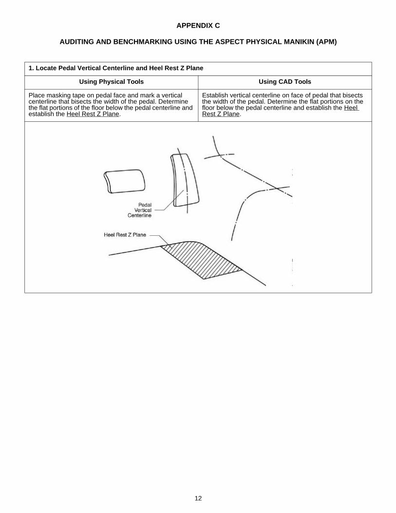
1. Locate Pedal Vertical Centerline and Heel Rest Z Plane
Using Physical Tools Using CAD Tools
Place masking tape on pedal face and mark a vertical centerline that bisects the width of the pedal. Determine the flat portions of the floor below the pedal centerline and establish the Heel Rest Z Plane.
Establish vertical centerline on face of pedal that bisects the width of the pedal. Determine the flat portions on the floor below the pedal centerline and establish the Heel Rest Z Plane.
13
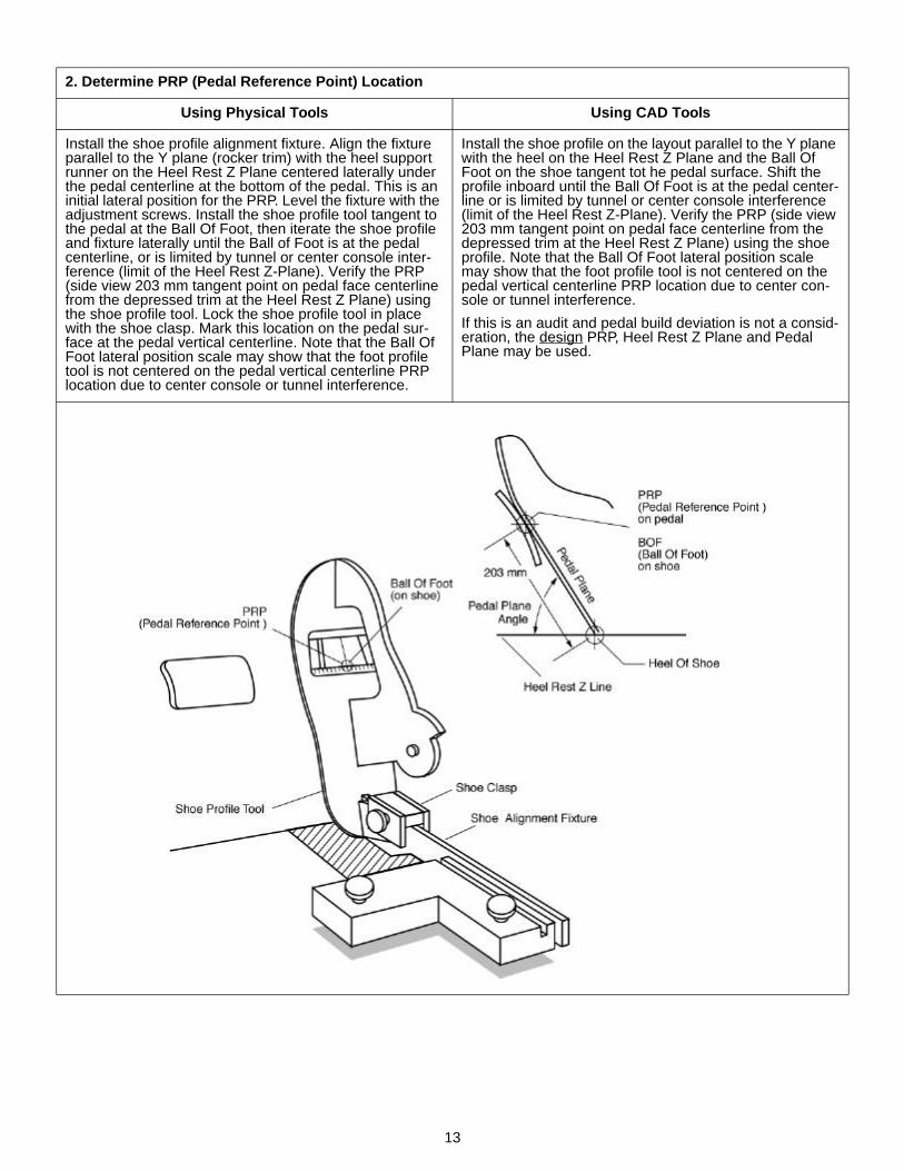
2. Determine PRP (Pedal Reference Point) Location
Using Physical Tools Using CAD Tools
Install the shoe profile alignment fixture. Align the fixture parallel to the Y plane (rocker trim) with the heel support runner on the Heel Rest Z Plane centered laterally under the pedal centerline at the bottom of the pedal. This is an initial lateral position for the PRP. Level the fixture with the adjustment screws. Install the shoe profile tool tangent to the pedal at the Ball Of Foot, then iterate the shoe profile and fixture laterally until the Ball of Foot is at the pedal centerline, or is limited by tunnel or center console inter-ference (limit of the Heel Rest Z-Plane). Verify the PRP (side view 203 mm tangent point on pedal face centerline from the depressed trim at the Heel Rest Z Plane) using the shoe profile tool. Lock the shoe profile tool in place with the shoe clasp. Mark this location on the pedal sur-face at the pedal vertical centerline. Note that the Ball Of Foot lateral position scale may show that the foot profile tool is not centered on the pedal vertical centerline PRP location due to center console or tunnel interference.
Install the shoe profile on the layout parallel to the Y plane with the heel on the Heel Rest Z Plane and the Ball Of Foot on the shoe tangent tot he pedal surface. Shift the profile inboard until the Ball Of Foot is at the pedal center-line or is limited by tunnel or center console interference (limit of the Heel Rest Z-Plane). Verify the PRP (side view 203 mm tangent point on pedal face centerline from the depressed trim at the Heel Rest Z Plane) using the shoe profile. Note that the Ball Of Foot lateral position scale may show that the foot profile tool is not centered on the pedal vertical centerline PRP location due to center con-sole or tunnel interference.
If this is an audit and pedal build deviation is not a consid-eration, the design PRP, Heel Rest Z Plane and Pedal Plane may be used.
14
3. Determine Heel Rest Z Line and AHP to PRP Lateral Offset
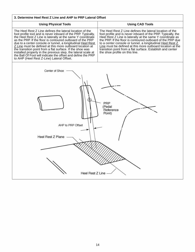
Using Physical Tools Using CAD Tools
The Heel Rest Z Line defines the lateral location of the foot profile tool and is never inboard of the PRP. Typically, the Heel Rest Z Line is laterally at the same Y coordinate as the PRP. If the floor is contoured outboard of the PRP due to a center console or tunnel, a longitudinal Heel Rest Z Line must be defined at this more outboard location at the transition point from a flat surface. If the shoe was installed properly in the previous step, the lateral scale at the Ball Of Foot will indicate the offset and define the PRP to AHP (Heel Rest Z-Line) Lateral Offset.
The Heel Rest Z Line defines the lateral location of the foot profile and is never inboard of the PRP. Typically, the Heel Rest Z Line is laterally at the same Y coordinate as the PRP. If the floor is contoured outboard of the PRP due to a center console or tunnel, a longitudinal Heel Rest Z Line must be defined at this more outboard location at the transition point from a flat surface. Establish and center the shoe profile on this line.

15
4. Determine Pedal Plane Angle
Using Physical Tools Using CAD Tools
Slide the shoe angle protractor against the shoe and read the angle. At this shoe profile tool position the angle indi-cates the Pedal Plane Angle.
At this shoe profile position, the side view angle of the Bot-tom Of Shoe from the horizontal defines the Pedal Plane Angle.
16
5. Place All Seat Adjustments at Design or Default Positions
This step must consider the differences between auditing and benchmarking. Auditing will use design settings where asbenchmarking will require standard settings established for comparative purposes. Table C1 lists default settings for use inbenchmarking.
6. Load the APM in the Seat and Record Data
Record H-Point coordinates, Cushion Angle, Back Angle, Lumbar Support Prominence and other seat measures asneeded. The ASPECT Physical Manikin loading procedure is described in Appendix A.
Table C1. Default Seat Adjustments for Use in Benchmarking Measurements
Adjustment SettingSeat Cushion Angle (seats without height adjustment) Middle of rangeSeat Cushion Angle (seats with height adjustment) Angle obtained with the seat full down/rearSeatback Angle (Class A vehicles: passenger cars, station wagons, MPVs and light trucks)
22 degrees, as measured with the ASPECT manikin
Seatback Angle (Class B vehicles: heavy trucks and buses) 18 degrees, as measured with the ASPECT manikinLumbar Support Prominence Minimum settingLumbar Support Height Middle of rangeSeat Bolsters Minimum, least restrictive setting
7. Determine the H-Point Travel Path
Using Physical Tools Using CAD Tools
Determine the H-Point travel path from points on the seat as the seat is adjusted through the extremes of the travel path. While these data can be obtained from the vehicle seat, the information must usually be translated to a draw-ing or CAD system to determine SgRP location.
Plot the H-Point travel path according to the extremes of the travel path.
If this is an audit and seat adjuster build deviation is not a consideration, the design travel path may be used.
17
8. Determine SgRP location and obtain Seat Height (H30)
Using Physical Tools Using CAD Tools
(Use procedures for CAD tools.) Calculate or determine SgRP location at the intersection of the H-Point travel path and the SgRP line. If the H-Point travel path includes vertical travel, define the SgRP at the midpoint between the upper and lower intersections between the travel path and the SgRP locator line. The SgRP line is a function of Seat Height H30 and is refer-enced to the Pedal Reference Point for x and Heel Rest Z Plane for z. Position the seat at the SgRP and determine H30. This step is typically done on a drawing board or in CAD.
SgRPx = 1038.2 – 0.3945 (H30)
18
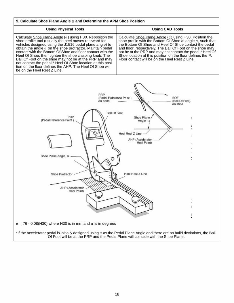
9. Calculate Shoe Plane Angle αα and Determine the APM Shoe Position
Using Physical Tools Using CAD Tools
Calculate Shoe Plane Angle (α) using H30. Reposition the shoe profile tool (usually the heel moves rearward for vehicles designed using the J1516 pedal plane angle) to obtain the angle α on the shoe protractor. Maintain pedal contact with the Bottom Of Shoe and floor contact with the Heel Of Shoe, then tighten the shoe clasping knob. The Ball Of Foot on the shoe may not be at the PRP and may not contact the pedal.* Heel Of Shoe location at this posi-tion on the floor defines the AHP. The Heel Of Shoe will be on the Heel Rest Z Line.
Calculate Shoe Plane Angle (α) using H30. Position the shoe profile with the Bottom Of Shoe at angle α, such that the Bottom Of Shoe and Heel Of Shoe contact the pedal and floor, respectively. The Ball Of Foot on the shoe may not be at the PRP and may not contact the pedal.* Heel Of Shoe location at this position on the floor defines the P. Floor contact will be on the Heel Rest Z Line.
α = 76 - 0.08(H30) where H30 is in mm and α is in degrees
*If the accelerator pedal is initially designed using α as the Pedal Plane Angle and there are no build deviations, the Ball Of Foot will be at the PRP and the Pedal Plane will coincide with the Shoe Plane.
19
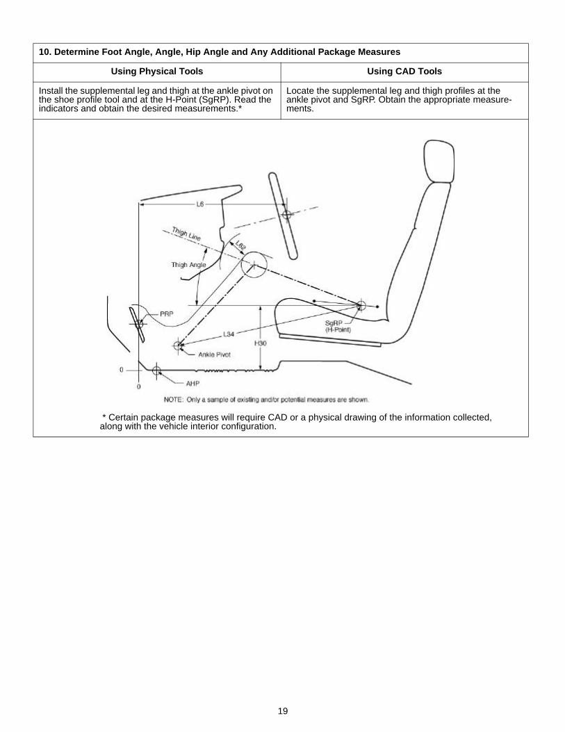
10. Determine Foot Angle, Angle, Hip Angle and Any Additional Package Measures
Using Physical Tools Using CAD Tools
Install the supplemental leg and thigh at the ankle pivot on the shoe profile tool and at the H-Point (SgRP). Read the indicators and obtain the desired measurements.*
Locate the supplemental leg and thigh profiles at the ankle pivot and SgRP. Obtain the appropriate measure-ments.
* Certain package measures will require CAD or a physical drawing of the information collected, along with the vehicle interior configuration.
20
APPENDIX D
SEAT DIMENSIONS AND REFERENCE POINTS
This appendix was developed from the technical report ofthe ASPECT IAP Seat Dimensions Task Group Report.This task group was formed to develop seat dimensionsfor potential inclusions in SAE J1100. Objectives of thegroup were to proposed seat geometry reference pointsand measurement definitions that would:
1. Facilitate geometric evaluation of seats using theASPECT Physical Manikin (APM), and
2. Provide the basis for future revisions to SAE J1100(Motor Vehicle Dimensions).
To meet these objectives two types of seat geometry ref-erence points and measurements were developed:
• ASPECT Physical Manikin dependent, that utilize theseat characterization capabilities of the APM toquantify seat measurements.
• ASPECT Physical Manikin independent, that providesimple field measures obtained without the use of theAPM. These measures are described at locations onthe seat that approximate the location of similarlydefined APM measures.
These measurement proposals were initially presented atthe June 1998 IAP meeting and have been updated toagree with ASPECT Physical Manikin development as ofDecember 11, 1998. Additional updates will be requiredas the APM is validated and finalized. Comments andalternative proposals will be welcomed.
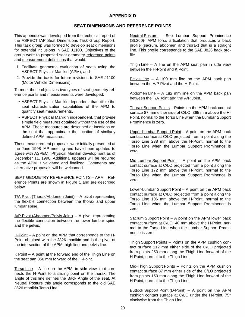
SEAT GEOMETRY REFERENCE POINTS – APM Ref-erence Points are shown in Figure 1 and are describedbelow.
T/A Pivot (Thorax/Abdomen Joint) – A pivot representingthe flexible connection between the thorax and upperlumbar spine.
A/P Pivot (Abdomen/Pelvis Joint) – A pivot representingthe flexible connection between the lower lumbar spineand the pelvis.
H-Point – A point on the APM that corresponds to the H-Point obtained with the J826 manikin and is the pivot atthe intersection of the APM thigh line and pelvis line.
K Point – A point at the forward end of the Thigh Line onthe seat pan 356 mm forward of the H-Point.
Torso Line – A line on the APM, in side view, that con-nects the H-Point to a sliding point on the thorax. Theangle of this line defines the Back Angle of the seat. AtNeutral Posture this angle corresponds to the old SAEJ826 manikin Torso Line.
Neutral Posture – See Lumbar Support Prominence(SL260)- APM torso articulation that produces a backprofile (sacrum, abdomen and thorax) that is a straightline. This profile corresponds to the SAE J826 back pro-file.
Thigh Line – A line on the APM seat pan in side viewbetween the H-Point and K Point.
Pelvis Line – A 100 mm line on the APM back panbetween the A/P Pivot and the H-Point.
Abdomen Line – A 182 mm line on the APM back panbetween the T/A Joint and the A/P Joint.
Thorax Support Points – Points on the APM back contactsurface 87 mm either side of C/LO, 365 mm above the H-Point, normal to the Torso Line when the Lumbar SupportProminence is zero.
Upper-Lumbar Support Point – A point on the APM backcontact surface at C/LO projected from a point along theTorso Line 238 mm above the H-Point, normal to theTorso Line when the Lumbar Support Prominence iszero.
Mid-Lumbar Support Point – A point on the APM backcontact surface at C/LO projected from a point along theTorso Line 172 mm above the H-Point, normal to theTorso Line when the Lumbar Support Prominence iszero.
Lower-Lumbar Support Point – A point on the APM backcontact surface at C/LO projected from a point along theTorso Line 106 mm above the H-Point, normal to theTorso Line when the Lumbar Support Prominence iszero.
Sacrum Support Point – A point on the APM lower backcontact surface at C/LO, 40 mm above the H-Point, nor-mal to the Torso Line when the Lumbar Support Promi-nence is zero.
Thigh Support Points – Points on the APM cushion con-tact surface 112 mm either side of the C/LO projectedfrom points 250 mm along the Thigh Line forward of theH-Point, normal to the Thigh Line.
Mid-Thigh Support Points – Points on the APM cushioncontact surface 87 mm either side of the C/LO projectedfrom points 150 mm along the Thigh Line forward of theH-Point, normal to the Thigh Line.
Buttock Support Point (D-Point) – A point on the APMcushion contact surface at C/LO under the H-Point, 75°clockwise from the Thigh Line.
21
Stiffness – Percent load per trim deflections at given sup-port points. Since stiffness may not be linear this may bebest expressed as a plot of percent load versus trimdeflection.
Breakaway – Locations where the deflected trim sepa-rates from the manikin surface.
Mean Head Profile – Reference manikin mean malehead with hair, referenced to the Back Angle.
Figure 1. ASPECT Physical Manikin seat geometry reference points and definitions.
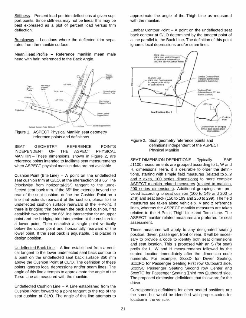
SEAT GEOMETRY REFERENCE POINTSINDEPENDENT OF THE ASPECT PHYSICALMANIKIN – These dimensions, shown in Figure 2, arereference points intended to facilitate seat measurementswhen ASPECT physical manikin data are not available.
Cushion Point (Bite Line) – A point on the undeflectedseat cushion trim at C/LO, at the intersection of a 65° line(clockwise from horizontal-25°) tangent to the unde-flected seat back trim. If the 65° line extends beyond therear of the seat cushion, define the Cushion Point on aline that extends rearward of the cushion, planar to theundeflected cushion surface rearward of the H-Point. Ifthere is bridging trim between the back and cushion, firstestablish two points; the 65° line intersection for an upperpoint and the bridging trim intersection at the cushion fora lower point. Then establish a single point verticallybelow the upper point and horizontally rearward of thelower point. If the seat back is adjustable, it is placed indesign position.
Undeflected Back Line – A line established from a verti-cal tangent to the lower undeflected seat back contour toa point on the undeflected seat back surface 350 mmabove the Cushion Point at CL/O. The definition of thesepoints ignores local depressions and/or seam lines. Theangle of this line attempts to approximate the angle of theTorso Line as measured with the manikin..
Undeflected Cushion Line – A Line established from theCushion Point forward to a point tangent to the top of theseat cushion at CL/O. The angle of this line attempts to
approximate the angle of the Thigh Line as measuredwith the manikin.
Lumbar Contour Point – A point on the undeflected seatback contour at C/LO determined by the tangent point ofa line parallel to the Back Line. The definition of this pointignores local depressions and/or seam lines.
Figure 2. Seat geometry reference points and definitions independent of the ASPECT Physical Manikin
SEAT DIMENSION DEFINITIONS – Typically SAEJ1100 measurements are grouped according to L, W andH. dimensions. Here, it is desirable to order the defini-tions, starting with simple field measures (related to x, yand z axes, 100 series dimensions) to more complexASPECT manikin related measures (related to manikin,200 series dimensions). Additional groupings are pro-vided according to seat cushion (100 to 149 and 200 to249) and seat back (150 to 199 and 250 to 299). The fieldmeasures are taken along vehicle x, y and z referencelines, whereas the ASPECT manikin measures are takenrelative to the H-Point, Thigh Line and Torso Line. TheASPECT manikin related measures are preferred for seatassessment.
These measures will apply to any designated seatingposition; driver, passenger, front or rear. It will be neces-sary to provide a code to identify both seat dimensionsand seat location. This is proposed with an S (for seat)prefix for L, W and H measurements followed by theseated location immediately after the dimension codenumerals. For example, SxxxD for Driver Seating,SxxxFO for Passenger Seating First row Outboard side,SxxxSC Passenger Seating Second row Center andSxxxTO for Passenger Seating Third row Outboard side.The proposed dimension definitions that follow are for thedriver.
Corresponding definitions for other seated positions arethe same but would be identified with proper codes forlocation in the vehicle.
22
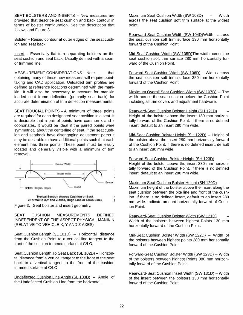
SEAT BOLSTERS AND INSERTS – New measures areprovided that describe seat cushion and back contour interms of bolster configuration. See the description thatfollows and Figure 3.
Bolster – Raised contour at outer edges of the seat cush-ion and seat back.
Insert – Essentially flat trim separating bolsters on theseat cushion and seat back, Usually defined with a seamor trimmed line.
MEASUREMENT CONSIDERATIONS – Note thatobtaining many of these new measures will require point-taking and CAD application. Unloaded trim profiles aredefined at reference locations determined with the mani-kin. It will also be necessary to account for manikinloaded seat frame deflection (primarily seat back) foraccurate determination of trim deflection measurements.
SEAT FIDUCIAL POINTS – A minimum of three pointsare required for each designated seat position in a seat. Itis desirable that a pair of points have common x and zcoordinates. It would be ideal if the paired points weresymmetrical about the centerline of seat. If the seat cush-ion and seatback have disengaging adjustment paths itmay be desirable to have additional points such that eachelement has three points. These point must be easilylocated and generally visible with a minimum of trimremoval.
Figure 3. Seat bolster and insert geometry.
SEAT CUSHION MEASUREMENTS DEFINEDINDEPENDENT OF THE ASPECT PHYSICAL MANIKIN(RELATIVE TO VEHICLE X, Y AND Z AXES)
Seat Cushion Length (SL 101D) – Horizontal distancefrom the Cushion Point to a vertical line tangent to thefront of the cushion trimmed surface at C/LO.
Seat Cushion Length To Seat Back (SL 102D) – Horizon-tal distance from a vertical tangent to the front of the seatback to a vertical tangent to the front of the cushiontrimmed surface at C/LO.
Undeflected Cushion Line Angle (SL 103D) – Angle ofthe Undeflected Cushion Line from the horizontal.
Maximum Seat Cushion Width (SW 103D) – Widthacross the seat cushion soft trim surface at the widestpoint.
Rearward-Seat Cushion Width (SW 104D)Width acrossthe seat cushion soft trim surface 130 mm horizontallyforward of the Cushion Point.
Mid-Seat Cushion Width (SW 105D)The width across theseat cushion soft trim surface 280 mm horizontally for-ward of the Cushion Point.
Forward-Seat Cushion Width (SW 106D) – Width acrossthe seat cushion soft trim surface 380 mm horizontallyforward of the Cushion Point.
Maximum Overall Seat Cushion Width (SW 107D) – Thewidth across the seat cushion below the Cushion Pointincluding all trim covers and adjustment hardware.
Rearward-Seat Cushion Bolster Height (SH 121D) –Height of the bolster above the insert 130 mm horizon-tally forward of the Cushion Point. If there is no definedinsert, default to an insert 280 mm wide.
Mid-Seat Cushion Bolster Height (SH 122D) – Height ofthe bolster above the insert 280 mm horizontally forwardof the Cushion Point. If there is no defined insert, defaultto an insert 280 mm wide.
Forward-Seat Cushion Bolster Height (SH 123D) –Height of the bolster above the insert 380 mm horizon-tally forward of the Cushion Point. If there is no definedinsert, default to an insert 280 mm wide.
Maximum Seat Cushion Bolster Height (SH 120D) –Maximum height of the bolster above the insert along theseat cushion between the bite line and front of the cush-ion. If there is no defined insert, default to an insert 280mm wide. Indicate amount horizontally forward of Cush-ion Point.
Rearward-Seat Cushion Bolster Width (SW 121D) –Width of the bolsters between highest Points 130 mmhorizontally forward of the Cushion Point.
Mid-Seat Cushion Bolster Width (SW 122D) – Width ofthe bolsters between highest points 280 mm horizontallyforward of the Cushion Point.
Forward-Seat Cushion Bolster Width (SW 123D) – Widthof the bolsters between highest Points 380 mm horizon-tally forward of the Cushion Point.
Rearward-Seat Cushion Insert Width (SW 131D) – Widthof the insert between the bolsters 130 mm horizontallyforward of the Cushion Point.
23
Mid-Seat Cushion Insert Width (SW 132D) – Width of theinsert between the bolsters 280 mm horizontally forwardof the Cushion Point.
Forward-Seat Cushion Insert Width (SW 133D) – Widthof the insert between the bolsters 380 mm horizontallyforward of the Cushion Point.
Maximum Seat Cushion Insert Width (SW 130D) – Maxi-mum width of the insert between the bolsters along theseat cushion forward of the Cushion Point. Indicate theamount horizontally forward of Cushion Point. In certaincases insert width is not definable.
SEAT CUSHION DIMENSIONS MEASURED RELATIVETO ASPECT PHYSICAL MANIKIN GEOMETRY –These measurements are made relative to lines and ref-erence points defined using the ASPECT Physical Mani-kin. Figure 4 depicts these dimensions.
Cushion Angle (SL 227D) – Angle of the Thigh Line fromthe horizontal with the APM loaded in the seat with theseat at design attitude.
Seat Cushion Length To H-Point (SL 201D) – Distancefrom the H-Point parallel to the Thigh Line to a line nor-mal (90°) to the Thigh Line tangent to the front of thecushion at C/LO.
Seat Cushion Width At H-Point (SW 204D) – Widthacross the seat cushion soft trim surface at the H-Pointon a plane normal (90°) to the Thigh Line (CushionAngle).
Seat Cushion Width At Mid-Thigh Support Point (SW205D) – Width across the seat cushion soft trim surface150 mm forward of the H-Point along the Thigh Line(Cushion Angle) on a plane normal (90°) to the ThighLine.
Seat Cushion Width At Thigh Support Point (SW 206D) –Width across the seat cushion soft trim surface 250 mmforward of the H-Point along the Thigh Line (CushionAngle) on a plane normal (90°) to the Thigh Line.
Seat Cushion Breakaway To H-Point (SL 209D) – Dis-tance from the H-Point to the breakaway point on theAPM thigh pan measured parallel to the Thigh Line(Cushion Angle). This measure is taken at the mean oftwo points on the underside of the thigh pan 112 mmeach side of C/LO. If the seat cushion is adjustable, it isplaced in design position.
Seat Cushion Bolster Height At H-Point (SH 221D) –Height of the bolsters above the insert along the seatcushion at the H-Point, normal (90°) to the Thigh Line(Cushion Angle). If there is no defined insert, default toan insert 280 mm wide.
Seat Cushion Bolster Height At Mid-Thigh Support Point(SH 222D) – Height of the bolsters above the insert alongthe seat cushion 150 mm forward of the H-Point, normal(90°) to the Thigh Line (Cushion Angle). If there is nodefined insert, default to an insert 280 mm wide.
Seat Cushion Bolster Height At Thigh Support Point (SH223D) – Height of the bolsters above the insert along theseat cushion 250 mm forward of the H-Point normal (90°)to the Thigh Line (Cushion Angle). If there is no definedinsert, default to an insert 280 mm wide.
Seat Cushion Bolster Width At H-Point (SW 221D) –Width between the highest points on the bolsters at theH-Point.
Seat Cushion Bolster Width At Mid-Thigh Support Point(SW 222D) – Width between the highest points on thebolsters 150 mm forward of the H-Point, normal (90°) tothe Thigh Line (Cushion Angle).
Seat Cushion Bolster Width At Thigh Support Point (SW223D) – Width between the highest points on the bolsters250 mm forward of the H-Point, normal (90°) to the ThighLine (Cushion Angle).
Seat Cushion Insert Width At H-Point (SW 231D) –Width of the insert between the bolsters along the seatcushion at the H-Point. In certain cases this measure isnot definable.
Seat Cushion Insert Width At Mid-Thigh Support Point(SW 232D) – Width of the insert between the bolsters150 mm forward of the H-Point, normal (90°) to the ThighLine (Cushion Angle). In certain cases this measure isnot definable
Seat Cushion Insert Width At Thigh Support Point (SW233D) – Width of the insert between the bolsters 250 mmforward of the H-Point, normal (90°) to the Thigh Line(Cushion Angle). In certain cases this measure is notdefinable
Buttock Support Trim deflection (SH 241D) – Distancefrom the Buttock Support Points to the undeflected seatcushion surface measured normal (90°) to the Thigh Line(Cushion Angle).
Mid-Thigh Support Trim Deflection (SH 242D) – Distancefrom the Mid-Thigh Support Points to the undeflectedseat cushion surface measured normal (90°) to the ThighLine (Cushion Angle).
Thigh Support Trim Deflection (SH 243D) – Distancefrom the Thigh Support Points to the undeflected seatcushion surface measured normal (90°) to the Thigh Line(Cushion Angle).

24
Buttock Stiffness (SH 245D) – Predetermined loadsdivided by the displacement of the Buttock Support Point.Since stiffness may not be linear, this measure has sev-eral reported values and may be best expressed in graphform.
Thigh Stiffness (SH 246D) – Predetermined loadsdivided by the displacement of the Thigh Support Points.Since stiffness may not be linear, this measure has sev-eral reported values and may be best expressed in graphform.
Figure 4. Seat geometry measurements made with respect to ASPECT Physical Manikin geometry.
SEAT BACK MEASUREMENTS DEFINEDINDEPENDENT OF THE ASPECT PHYSICAL MANIKIN(RELATIVE TO VEHICLE X, Y AND Z AXES)
Seat Back Height Without Head Restraint (SH 151D) –Vertical distance from the Cushion Point to a horizontalline tangent to the top of the seat back trimmed surface atC/LO. If the seat back is adjustable, it is placed in designposition.
Seat Back Height With Head Restraint (SH 152D) – Ver-tical distance from the Cushion Point to a horizontal linetangent to the top of the head restraint trimmed surface atC/LO. If the seat back is adjustable, it is placed in designposition. If the headrest is adjustable, it is placed in thefull down position. Note that if the seat has an integralheadrest, the previously defined measure “Seat backHeight Without Head Restraint” is not taken.
Lumbar Contour Height (SH 153D) – Vertical distancefrom the Cushion Point to the Lumbar Contour Point at C/LO. If the seat back is adjustable, it is placed in designposition.
Seat Back Width (SW 155D) – The width across the softtrim surface at the widest point.
Maximum Seat Back Width (SW 150D) – Width acrossthe back including all trim covers and adjustment hard-ware.
Lower Seat Back Width Cushion Point (SW 154D) –Width of the soft trim 70 mm above the Cushion Point.
Mid-Seat Back Width (SW 152D) – Width of the soft trim200 mm above the Cushion Point.
Upper Seat Back Width (SW 151D) – Width of the softtrim 330 mm above the Cushion Point.
Lower Seat Back Bolster Depth (SL 161D) – Offset of thebolsters horizontally forward of the insert 70 mm abovethe Cushion Point. If there is no defined insert, default toan insert 280 mm wide. If the seat back is adjustable it isplaced in design position.
Mid-Seat Back Bolster Depth (SL 162D) – Offset of thebolsters horizontally forward of the insert 200 mm abovethe Cushion Point. If there is no defined insert, default toan insert 280 mm wide. If the seat back is adjustable it isplaced in design position.
Upper Seat Back Bolster Depth (SL 163D) – Offset of thebolsters horizontally forward of the insert 330 mm abovethe Cushion Point. If there is no defined insert, default toan insert 280 mm wide. If the seat back is adjustable it isplaced in design position.
Maximum Seat Back Bolster Depth (SL 160D) – Maxi-mum depth of the bolster forward of the insert above theabove the Cushion Point-Line. If there is no definedinsert, default to an insert 280 mm wide. Indicate amountabove or below the Lumbar Contour Point. If the seatback is adjustable, it is placed in design position.
Undeflected Back Line Angle (SL164D) – Angle of theundeflected Back Line from the vertical.
Lower Seat Back Bolster Width (SW 163D) – Width ofthe bolsters between most forward points 70 mm abovethe Cushion Point.
Mid-Seat Back Bolster Width (SW 162D) – Width of thebolsters between most forward Points 200 mm above theCushion Point.
Upper Seat Back Bolster Width (SW 161D) – Width ofthe bolsters between most forward Points 330 mm abovethe Cushion Point.
Lower Seat Back Insert Width (SW 173D) – Width of theinsert between the bolsters 70 mm above the CushionPoint. In certain cases this measure is not definable.
Mid-Seat Back Insert Width (SW 172D) – Width of theinsert between the bolsters 200 mm above the CushionPoint. In certain cases this measure is not definable.

25
Upper Seat Back Insert Width (SW 171D) – Width of theinsert between the bolsters 330 mm above the CushionPoint. In certain cases this measure is not definable.
SEAT BACK DIMENSIONS MEASURED RELATIVE TOTHE ASPECT PHYSICAL MANIKIN – Seat back dimen-sions are illustrated in Figure 4.
Unloaded Back Angle Differential (SL 251D) – Effectiveback angle change between no load and APM load rela-tive to design Back Angle. Use fiducial points on seatback to measure loaded and unloaded angle change.
Back Angle (SL 250D) – Angle of the Torso Line from thevertical with the reference manikin loaded in the seat withthe seat at design attitude as specified by the manufac-turer. The ASPECT procedures may require a specifiedback angle for consistent measurement of seat charac-teristics. A specified Back Angle would only be applicablefor adjustable seat backs unless the specified angle wasused as the fixed back design angle. An additional defini-tion would be required for fixed seat backs (SL 241?).Specified Back Angle (SL 240) could read, Angle of theTorso line from the vertical with the reference manikinloaded in the seat with the seat at design attitude is asfollows:
Class A vehicles------------22°
Class B vehicles------------18°
Values for these specified angles would be finalizedbased on observed usage in the corresponding vehicletypes with nominal package geometry. Note that this defi-nition of Back Angle added in parenthesis is not part ofthe IAP Seat Dimensions Task Group study but part ofASPECT application considerations that are under studyat UMTRI.
Lumbar Support Prominence (SL 260) – Displacement ofthe side view centerline profile of the APM lumbar seatcontact surface relative to the position at neutral posturewith the reference manikin loaded in the seat at designsettings. Zero prominence is defined when the back pro-file of the manikin is a straight line (old SAE J826 con-tour). Values greater than 0 indicate a concave profile. Ifthere is adjustable lumbar support, maximum and mini-mum Lumbar Support Prominence values may beobtained by repeating a manikin drop at each of theextreme settings. Generally Lumbar Support Prominence(and H-Point location) will be determined at the minimumsetting.
Seat Back Height From H-Point Without Head Restraint(SH 251D) Distance from the H-Point along the TorsoLine (Seat Back Angle) to the intersection at a line nor-mal to the Torso Line, tangent to the top of the seat backat CL/O. Head restraint is excluded. If the seat back isadjustable, it is placed in design position.
Seat Back Height From H-Point With Head Restraint (SH252D) – Distance from the H-Point along the Torso Lineto the intersection at a line normal (90°) to the Torso Line,tangent to the top of the headrest at C/LO. If the seatback is adjustable, it is placed in design position. If thehead restraint is adjustable it is placed in the full downposition. If the seat has an integral head restraint, thepreviously measure “Seat back Height To H-Point withoutHead Restraint” is not taken. This dimension is similar toECE Head Restraint Height.
Seat Back Breakaway To H-Point (SH 259D) – Distancefrom the H-Point to the breakaway points on the manikinback measured parallel to the Torso Line. This measureis taken at the mean of two points on the back of the backpan 87 mm each side of C/LO. If the seat back is adjust-able, it is placed in design position.
Seat Back Width At Thorax Support Point (SW 251D) –Width across the soft trim surface in a plane normal (90°)to the Torso Line at the Thorax Support Point.
Seat Back Width At Mid-Lumbar Support Point (SW 252) –Width across the soft trim surface in a plane normal (90°)to the Torso Line at the Mid-Lumbar Support Point.
Seat Back Width At H-Point (DSW 254) – Width acrossthe soft trim surface in a plane normal (90°) to the TorsoLine at the H-Point.
Seat Back Bolster Depth At Thorax Support Point (DSL261D) – Offset of the bolsters forward of the insert nor-mal (90°) to the Torso Line at the Thorax Support Point. Ifthere is no defined insert, default to an insert 280 mmwide. If the seat back is adjustable it is placed in designposition.
Seat Back Bolster Depth At Mid-Lumbar Support Point(SL 262D) – Offset of the bolsters forward of the insertnormal (90°) to the Torso Line at the Mid-Lumbar SupportPoint. If there is no defined insert, default to an insert 280mm wide. If the seat back is adjustable it is placed indesign position.
Seat Back Bolster Depth At H-Point (SL 264D) – Offsetof the bolsters forward of the insert normal (90°) to theTorso Line at the H-Point. If there is no defined insert,default to an insert 280 mm wide. If the seat back isadjustable it is placed in design position.
Seat Back Bolster Width At Thorax Support Point (W261D) – Width of the bolsters between most forwardpoints in a plane normal (90°) to the Torso Line at theThorax Support Point.
Seat Back Bolster Width At Mid-Lumbar Support Point(SW 262D) – Width of the bolsters between most forwardpoints in a plane normal (90°) to the Torso Line at theMid-Lumbar Support Point.
26
Seat Back Bolster Width At The H-Point (SW 264D) –Width of the bolsters between most forward points in aplane normal (90°) to the Torso Line at the H-Point.
Seat Back Insert Width At Thorax Support Point (SW271D) – Width of the insert between the bolsters in aplane normal (90°) to the Torso Line at the Thorax Sup-port Point.
Seat Back Insert Width At Mid-Lumbar Support Point(SW 272D) – Width of the insert between the bolsters ina plane normal (90°) to the Torso Line at the Mid-LumbarSupport Point.
Seat Back Insert Width At H-Point (SW 274D) – Width ofthe insert between the bolsters in a plane normal (90°) tothe Torso Line at the H-Point.
Thorax Support Trim Deflection (SL 281D) – Distancefrom the Thorax Support Point on the manikin to theundeflected trim, measured normal (90°) to the TorsoLine.
Mid-Lumbar Support Trim Deflection (SL 282D) – Dis-tance from the Mid-Lumbar Support Point on the manikinto the undeflected trim, measured normal (90°) to theTorso Line with the seat at design Back Angle.
Sacral Support Trim Deflection (SL 284D) – Distancefrom the Sacrum Support Point on the manikin to theundeflected trim, measured normal (90°) to the TorsoLine with the seat at design Back Angle. If the manikinsurface does not reach the trim, this measure is rede-fined Sacral Relief (SL 285D).
HEAD RESTRAINT MEASUREMENTS
Head Clearance To Head Restraint (SL 301D) – Dis-tance from the back of the Mean Head Profile normal tothe Torso Line to a plane parallel to the Torso Line tan-gent to the front surface of the head restraint at CL/O.
Top Of Head To Top Of Head Restraint (SH 302D) – Ver-tical distance from top of Mean Head Profile to top ofhead restraint trimmed surface at CL/O. This value isnegative if the head is below the restraint.
Head Restraint Width (SW 303D) – Width acrosstrimmed surfaces of the head restraint at widest points.
Head Restraint Height (SH 304D) – Vertical heightacross trimmed surfaces of head restraint at CL/O.
Head Restraint Depth (SL 305D) – Horizontal Depthacross trimmed surfaces of head restraint at CL/O.
TORSO RESTRAINT MEASUREMENTS (SEATBELTS) – See Regulation 14, Uniform Provisions Con-cerning The Approval Of Vehicles With Regard To Safety-Belt Anchorages, E/ECE/324, E/ECE/TRANS/505, 16December 1992
NOTES ON DEVELOPMENT OF SEAT DIMENSIONS – Seat dimensional data were collected and reviewed bythe ASPECT IAP Seat Dimensions Task Group todevelop a set of measures that would be useful to evalu-ate the geometry of automotive seats. The seat measure-ment proposals assembled in this document are theresult of this effort.
Dimensional data from existing production seats wereused to develop measurement definitions for bolster andinsert geometry on seat cushions and seat backs as wellas cushion lengths and back heights. Many of theseseats were used to develop Cushion Point and LumbarContour Point definitions. The various measures aredescribed in Figure 1.
Vehicles used at UMTRI for various driver seating andpackaging studies had been previously measured indetail. These seats were H-Point checked and surfacescanned and therefore provided an excellent set of “asmeasured” data available in drawing form. It must benoted, however that the dimensional H-Point data isrelated to the present J826 manikin. The data mayrequire some adjustment to reflect ASPECT measure-ments. The measurement descriptions are provided inFigure 1, 2, 3, and 4.
These vehicle seat drawings were use to refine the Cush-ion Point, Lumbar Contour Point and Lumbar SupportPoint definitions and develop the Back Line and CushionLine definitions. The field measurement locations of bol-ster and insert geometry as well as cushion and backwidths were adjusted to fit the locations for the manikinrelated measures. This was accomplished by studyingthe horizontal and vertical relationships between Cush-ion-Point and H-Point. The x axis difference between H-Point and Cushion-Point is generally consistent (115 mmto 145 mm) with a mean value of 130 mm. This value wasused to “align” the location of reference points locationsfor field measurements with manikin H-Point dependentmeasures for seat cushion and seat back geometry. Ver-tical H-Point to Cushion-Point data varies more, in onecase due to a seat with extensive bridging trim betweenthe seat back and cushion. Excluding the one unusualcase resulted in a mean value of 83 mm. The relation-ships between manikin independent (field) and manikindependent measures are defined as follows:
Seat Cushion – manikin independent measures horizon-tally forward of Cushion Point, 130 mm, 280 mm and 380mm correspond to manikin dependent measures forwardof H-Point along the Thigh Line of 0 mm, 150 mm and350 mm respectively. Note that an 130 mm horizontal off-
27
set from H-Point to Cushion Point is used. Typical Cush-ion Angles (15°) and projection of the manikin dependentmeasures normal from the Thigh Line to the seat cushionsurface produces similar reference locations on the seatsurface for manikin independent (field) measurementsand manikin dependent measurement definitions.
Seat Back – manikin independent measures verticallyabove Cushion Point, 70 mm, 200 mm, and 330 mm cor-respond to manikin dependent measures above H-Pointalong the Torso Line of 40 mm, 172 mm, and 365 mm.Note that an 83 mm vertical offset from the H-Point to theCushion Point is used. Unlike the seat cushion, backangle geometry and offset of the manikin Torso Line tothe seat surface torso contact points complicate a directcomparison of the values. At a 20° Back Angle, 90° HipAngle, and at neutral posture, the manikin independentpoints (70 mm 200 mm, and 330 mm) translate, at seatcontact, to be very close to the 40 mm, 172 mm, and 365mm points relative to the manikin. Both manikin depen-dent and independent points are not yet finalized andmay be redefined at different locations.
A number of different attempts were made to define BackLine. The goal was to produce a field measure (manikinindependent) for Back Line that would be generally paral-lel to the present manikin measured Torso Line. Theresulting definition is a line from a vertical tangent to thelower undeflected seat back contour to a point on theundeflected seat back surface 350 mm above the Cush-ion Point at CL/O. The definition of these points ignoreslocal depressions and/or seam lines.


![TOYOTA-TERMINOLOGIE [ ]- SAE-ABKÜRZUNGEN SAE …](https://img.dokumen.tips/doc/110x75/62bbb323bf7def5b7910eaf4/toyota-terminologie-sae-abkrzungen-sae-.jpg)


