Embed Size (px)
Citation preview

OES MEDICAL
USER MANUAL
CARINA ELECTRONIC
ANAESTHESIA VENTILATOR

2
Index
Index 2
Service and repairs 4
Warnings and cautions 5
Purpose 6
Ventilator description 7
Front panel – description 8
- On/off switch 8 - Expiratory time adjustment 8 - Flow adjustment 8 - Inspiratory time adjustment 8 - Airway pressure gauge 8 - Mute button 9 - LED alarm displays 9 - Trigger point adjustment 10 - High pressure alarm adjustment 10 - Bellows assembly 10
Front illustration 11
Rear panel description 12
- Mains inlet socket 12 - Mains fuse 12 - Pressure relief valve exhaust 12 - Drive gas exhaust 12 - Ventilator driving gas connector 12 - High pressure oxygen inlet 13 - Manometer connector 13 - Solenoid and spool valve exhaust 13 - Bellows patient connection 13
- Bellows unit exhaust port 14 - Bellows unit drive gas connector 14
Rear panel - illustration 15
Adult bellows description 16
- Bellows base assembly 16 - Bellows base screws 16 - Exhaust diaphragm assembly 16 - Exhaust diaphragm screws 16 - Adult bellows 16 - Adult bellow housing 17
Adult bellows assembly illustration 18
Ventilation cycle - description 19
Electronic pneumatic circuit - description 20

3
Breath per min, tidal volume and I:E ratio calculations 21
Specification 22
Ventilator standard parts 24
Ventilator set up procedure 25
Pre-use function test 26
Clinical operation 28
Fault finding 29
User maintenance - service schedule 30
Cleaning of the control unit 31
Cleaning and sterilisation of the bellows unit 32
Ordering information 33
User notes 34

4
Service and repairs
In order to achieve the full operational life of the CARINA ANAESTHESIA VENTILATOR the following service schedule must be adhered to: - (a) Three monthly inspection and service check. (b) Six monthly bellows replacement. (c) Two yearly replacement of exhaust diaphragm and battery. (d) Five yearly overhaul. Service requirements are detailed in the service manual that is available to factory-trained personnel. Further details are available from: - The Service department, OES MEDICAL LTD UNIT 10, AREA D, RADLEY ROAD INDUSTRIAL ESTATE, ABINGDON, OXFORDSHIRE, OX14 3RY, ENGLAND. Phone 01235 539618 Fax 01235 539619 Always provide the following information with any communication: - (a) Type of product and part number. (b) Product name. (c) Serial number. (d) Date of purchase. (e) Details of suspected fault.

5
Warnings and cautions
Throughout this manual warnings and cautions relating to various aspects of use of this ventilator are given. It is the responsibility of the user to read this manual and fully understand the functions of this ventilator prior to use. No clinical advise on the use of this ventilator is given or implied within this manual, the various technical functions are described and it’s use by the anaesthetist must be based on safe best clinical practice using all necessary additional patient monitoring considered necessary for patient safety.
The use of patient monitoring during the use of this anaesthesia ventilator is essential for patient safety.

6
Purpose The OES ORION VENTILATOR is an electronically controlled anaesthesia ventilator with bellows unit, designed for mechanical ventilation during anaesthesia. It can be used in closed circuit anaesthesia and to drive a Bain circuit.

7
Description
The OES CARINA VENTILATOR is a time cycled flow generator type ventilator that is provided with an ascending bellows unit, which is easily detachable for cleaning. Controls are provided for inspiratory time, expiratory time, flow rate and basic patient and ventilator alarm functions.

8
Front panel description
On/Off switch
The on/off switch is located on the top right hand side of the front panel.
Expiratory time control knob Calibrated between 0.5 and 6.0 seconds. Rotation of the knob in a clockwise direction increases the expiratory time. The expiratory time is electronically controlled.
Flow control knob Calibrated between 0.1 and 1.0 litres per second. Rotation of the grooved knob in an anti clockwise direction increases the flow rate. The tidal volume delivered to the patient is determined in the following way: - Tidal volume = inspiratory time x flow rate (litres) (seconds) (litres per second)
Inspiratory time control knob Calibrated between 0.25 and 3.0 seconds. Rotation of the knurled knob clockwise increases the inspiratory time. The inspiratory time is electronically controlled.
Airway pressure gauge Calibrated between -20 to +100 cm of water, the gauge must be connected to the inspiratory limb of the breathing circuit via the connector on the rear panel. The manometer is also connected internally to the pressure transducer on the electronic patient monitoring board.

9
Mute button
The mute button gives 15 second of alarm silence. The mute only applies to disconnect alarms.
LED alarm displays
Displays are provided to show the following ventilator conditions: - Mains supply – indicates that the ventilator is running from mains power. Low battery – indicates that the battery requires charging, normally due to use for to long without the mains power connected. Low drive gas pressure – indicates a low oxygen drive gas pressure below 40 psi. High airway pressure alarm – indicates that the patient airway pressure has exceeded that set on the adjustable high airway pressure alarm. Disconnect alarm – indicates that the patient circuit pressure has not exceeded the trigger point setting, which would suggest that the tidal volume is to low or that the patient connection has become disconnected. Continuous positive airway pressure alarm – indicates that the patient circuit pressure has not dropped below the set trigger point during the expiratory phase. Apnea alarm – indicates a negative pressure within the patient circuit of at least 5 cm H20. Mute – indicates that the alarm has been muted for 30 seconds. Note that this function is only available for certain alarm conditions such as disconnect, high airway alarm, apnea and continuous positive airway pressure. Low drive gas pressure cannot be muted.

10
Trigger point alarm adjustment.
The minimum patient airway circuit pressure is adjustable between 0 and 30 cm H20. The value set on the trigger point is the pressure that the patient circuit must reach or exceed during the inspiratory phase, failure to reach this pressure will result in an instant disconnect alarm. During the expiratory phase the patient circuit pressure must drop below the trigger point setting, failure to do so will result in a continuous positive airway pressure alarm (C.P.A.P).
High pressure alarm adjustment. The maximum patient airway pressure is adjustable between 30 and 70 cm H20. The value set on the high airway pressure alarm must be set just above the maximum required airway pressure to prevent an alarm during normal use. During the inspiratory phase if the patient circuit pressure reaches the maximum airway pressure there is an instant high pressure alarm and the inspiratory flow is stopped, with the ventilator going into expiratory mode for the balance of the inspiratory time.
Bellows unit assembly The bellows canister is marked with a scale, which allows the tidal volume to the patient to be determined with bellows movement. Further information on the bellows unit assembly is given on page 16, 17 and 18.

11
Front illustration
10
1
23456
7
8
9
1 On/off switch. 2 Expiratory time adjustment. 3 Flow adjustment. 4 Inspiratory time adjustment. 5 Airway pressure gauge. 6 Mute button. 7 LED alarm displays. 8 Trigger point adjustment. 9 High pressure alarm adjustment. 10 Bellows assembly.

12
Rear panel description
Mains inlet socket
The ventilator mains inlet supply is provided by a IEC style socket.
Mains fuses
Fuses are provided on both live and neutral and are 360 mA. The fuses are mounted in a holder which is an integral part of the mains inlet socket.
Pressure relief valve exhaust port The ventilator incorporates an over pressure relief valve which acts as a fail safe should the electronic high pressure alarm fail to activate. This exhaust port allows the drive gas to exhaust to atmosphere when the set pressure on the high pressure alarm is exceeded.
WARNING - do not attempt to block the exhaust port.
Drive gas exhaust port The exhaust port, which allows the drive gas to be exhausted from within the bellows canister (the outside of the bellows) as the bellows rise during the expiratory phase. This function is controlled by a silicone diaphragm, which is inflated during the inspiratory phase and deflates to allow gas flow during the expiratory phase.
WARNING - do not attempt to block the exhaust port.
Ventilator bellows driving gas connector A 17 mm male taper, which connects to the bellows drive gas connector with a flexible corrugated tube.

13
High pressure oxygen inlet A 1.5 metre long high pressure hose is supplied for connection to the DISS oxygen inlet connector with the other end suitable for connection to a mini Schrader style connector on the anaesthesia machine.
Manometer connection This connects to the 2.5 metres of silicone tube and the 22 mm taper male / female sensing tee which must be placed in the inspiratory limb of the patient breathing circuit.
Solenoid and spool valve exhaust port
The ventilator cycle is controlled by a solenoid driven by the electronic circuit; this solenoids function is to activate a pneumatic spool valve. Both the solenoid and spool valve require high pressure oxygen to be exhausted at the start of the expiratory phase or when the high pressure alarm setting is reached, this gas is exhausted through this port.
Bellows unit patient connection A 22 mm male taper connection, which connects to the patient circuit via 1.8 metre length of disposable corrugated tubing.

14
Bellows unit exhaust port A 30 mm taper to which the anaesthetic gas scavenge system must be connected.
WARNING - the anaesthetic gas scavenging system must not generate more than 0.5 cm H20 of negative or positive pressure. Failure to comply with this requirement will result in positive or negative pressure within the breathing circuit.
Bellows unit driving gas connector A 17 mm taper which connects to the ventilator bellows drive gas connector via a flexible corrugated tube.

15
Rear illustration
11
1
2
3456
8
9
7
10
1 Mains inlet socket. 2 Mains Fuses. 3 Pressure relief valve exhaust. 4 Drive gas exhaust. 5 Ventilator bellows driving gas connecter – 17 mm taper. 6 High pressure oxygen inlet. 7 Manometer connector. 8 Solenoid and spool valve exhaust port. 9 Bellows 22 mm Patient connection. 10 Bellows 30 mm scavenging connection. 11 Bellows unit drive gas connector.

16
Adult bellows assembly
Bellows base assembly The bellows base assembly is attached to the top of the ventilator case and incorporates an o seal for the bellows housing to seal against and an o seal to seal between the bellows base and the exhaust gas diaphragm assembly. An exhaust valve seat which allows the escape of exhaust gas to the bellows exhaust port on the rear of the assembly at the end of the expiratory phase is situated in the centre of the assembly.
WARNING- care must be taken not to damage the exhaust valve seat.
Bellows base screws
Thumb screws, which hold the bellows base to the top of the ventilator case. (4 off)
Exhaust diaphragm assembly This assembly contains a diaphragm and a sealing disc which seals on the exhaust valve seat in the bellows base during the expiratory phase.
Exhaust diaphragm assembly screws Thumb screws which hold the diaphragm assembly onto the bellows base assembly. (3 off)
Adult bellows The bellows are attached to the bellows base assembly by the lower convolution on the shoulder of the bellows base assembly.
Warning – care must be taken to ensure that the bellows is attached by it’s bottom convolution onto the bellows base shoulder, Failure to attach the bellows properly will result in the bellows drive gas diluting the patient circuit gas, with potentially serious consequences.

17
Adult bellows housing The adult bellows housing is located on the bellows base assembly by the location ring on the bellows base assembly it is then locked in position by twisting clockwise until the lugs are located in the bellows base assembly.

18
Bellows assembly illustration
6
5
4
3
2
1
1 Bellows base. 2 Bellows base screw. 3 Exhaust diaphragm assembly. 4 Exhaust diaphragm assembly screws. 5 Bellows. 6 Bellows cover.

19
Ventilator cycle - description (1) The bellows prior to the start of the inspiratory phase is fully inflated by the fresh gas flow from the anaesthetic machine and retains this position due to the weight of the exhaust diaphragm valve giving a slight back pressure within the bellows. (2) At the start of the inspiratory phase, drive gas from the ventilator enters the inside of the bellows housing and forces the bellows down driving the patient gas within the bellows into the breathing circuit. During the inspiratory phase the ventilator exhaust diaphragm inflates blocking the exhaust port and the bellows exhaust diaphragm is held shut by the pressure of the drive gas flow from the ventilator. (3) At the start of the expiratory phase the flow of drive gas from the ventilator ceases and the ventilator exhaust diaphragm deflates. This allows the drive gas within the bellows housing to exhaust through the ventilator drive gas exhaust port, as the bellows rise with the exhaled gas. Excess exhaled gas exhausts through the bellows exhaust port into the scavenging system.

20
Pneumatic and electronic circuit – description
The pneumatic circuit consists of a spool valve and an electrical solenoid valve, which control the flow of high pressure gas to the flow control valve and low pressure oxygen to the exhaust diaphragm. The spool valve is controlled by the electronic circuit, which during the inspiratory phase opens the solenoid. This in turn opens the spool valve to give a flow of oxygen to the flow control needle and also pressure from the low pressure regulator to inflate the ventilator exhaust diaphragm. At the expiratory phase the electronic circuit shuts the solenoid and the spool valve closes, the pressure in the exhaust diaphragm is exhausted through the exhaust port on the rear of the ventilator and the diaphragm deflates allowing the bellows to rise as the expired gas is driven back into the bellows from the patient. During use the inspiratory flow rate is stopped if the high pressure alarm setting is exceeded, the ventilator then goes into expiratory mode for the balance of the inspiratory time. If the trigger point setting is not reached during the inspiratory phase the disconnect alarm will sound. Failure to drop below the trigger point during the expiratory phase will cause the continuous positive airway pressure alarm to sound.
Note – the LED alarms latch to indicate what the alarm was; these are reset by pressing the mute button.

21
Calculations for breaths per minute, I:E ratio, minute and tidal
volume
Breathes per minute is determined in the following way: - B.P.M = 60 Inspiratory time + Expiratory time The I:E ratio is determined in the following way :- Inspiratory time I:E Ratio = Expiratory time
Note – the electronics of the ventilator prevents inverse I:E ratios from being selected – the minimum expiratory time is the same as the set inspiratory time. The tidal volume is determined in the following way: - Tidal volume = Inspiratory time x flow rate The tidal volume is determined in the following way: - Minute volume = Tidal volume x breathes per minute

22
Specification
(1) Application - adult and paediatric ventilation during anaesthesia. (2) Gas supply – oxygen (3) Gas supply pressure - 275 to 840 KPA (4) Gas supply hose - 1.5 metres of white anti-static hose fitted with a DISS fitting. (5) Hose end - mini Schrader or special order as required. (6) Patient airway pressure gauge - 63 mm diameter aneroid pressure gauge with -20 to +100 cm of water. (7) Ventilator to bellows connection - 17 mm taper. (8) Bellows to patient taper - 22 mm taper to BS 3049 (9) Bellows exhaust gas taper - 19 mm taper. (10) Inspiratory time range - 0.25 to 3.0 seconds. (11) Expiratory time range - 0.5 to 6.0 seconds. (12) Frequency range - 6.6 to 80 breaths per minute. (derived from inspiratory and expiratory times) (13) Inspiratory gas flow rate - 0.1 to 1.0 litre per second of oxygen. (14) Tidal volume range - 0.025 to 3.0 litres per breath. (derived from inspiratory time and inspiratory flow rate.
Note - the maximum tidal volume, which can be achieved is 1.6 litres due to the capacity of the bellows. (15) Minute volume range - derived from tidal volume and frequency. (16) Maximum relief pressure – 80 CM H2O. (17) I:E ratio - variable between 1:1 and 1:24

23
(18) Weight – 8.0 Kg (19) Dimensions - height of complete ventilator - 340 mm width - 300 mm depth - 260 mm (20) Sterilisation - for details on bellows assembly sterilisation see appropriate section. (22) Adjustable low pressure alarm 0 – 30 cm H20 (23) Adjustable high pressure alarm 10 – 70 cm H2O (24) Mute button – 15 seconds (25) Patient audible and visual alarms for disconnect/low airway pressure, high airway pressure, high continuous pressure, and sub ambient pressure. (26) Ventilator alarms for mains failure, low battery, and low drive gas pressure. (27) External power supply 90- 264 volts A.C. (28) Battery back up – 12 hours minimum.
24
Ventilator standard parts The ventilator is supplied with the following standard parts: - (1) High pressure drive hose. (specification as per order) (2) Ventilator to bellows drive hose. (3) Manometer tube. (4) Pressure sensing tee piece. ( 22 mm male/female taper) (5) Patient breathing system drive hose with male and female 22 mm taper connectors - 1.8 metre long. (6) Mains cable. (7) User manual.

25
Ventilator set up procedure
(1) Mounting the ventilator - the ventilator can be mounted either on the anaesthetic machine shelf, on the ASTRA anaesthesia machine dove tail bracket or on to a pole mount bracket plate. (to suit diameter 25.0 / 25.4 mm poles) It is attached by removing the feet from the ventilator and attaching the bracket in its place. This plate is an optional extra - see the spares section for details. (2) High pressure hose assembly - attach the hose to the ventilator, care must be taken to attain a leak free seal without over tightening the fitting. Attach the other end of the hose assembly to the high pressure oxygen supply. (3) Ventilator to bellows drive hose - attach the corrugated hose to both the ventilator drive gas taper and the bellows drive gas taper. (4) Mains power supply cable. (5) Manometer tube - attach the silicone tube to the manometer connection on the rear panel, place the pressure sensing tee piece in the inspiratory limb of the patient breathing circuit. (6) Patient breathing system drive hose - connect the 22 mm female taper to the bellows breathing system taper, connect the other end to the patient circuit. (7) Scavenging system - connect the exhaust port on the bellows unit to a scavenging system.
Warning - the anaesthetic gas scavenging system must not generate more than 0.5 cm H2O of negative or positive pressure. Failure to comply with this requirement will result in positive or negative pressure within the breathing circuit.
26
Pre use function test
(1) Ensure that the ventilator is correctly connected - refer to the ventilator set up procedure. (2) Set the adjustable pressure relief valve to the required setting. (3) Set the desired inspiratory time. (4) Set the desired expiratory time. (5) Set the desired flow rate. (6) Set the trigger point alarm. (7) Set the high pressure alarm. (8) Attach a 2 litre breathing bag to the patient connection as a breathing bag. (9) Fill the bellows by using the anaesthetic machine oxygen flush. (10) Turn the ventilator on and ensure that the ventilator delivers the correct tidal volume - this can be checked by the scale on the adult bellows housing or by using a flow sensor. (11) Adjust the flow rate and/or the Inspiratory time to achieve a circuit pressure low than the trigger setting and ensure that a disconnect alarm occurs. Check the mute button function. (12) Prevent the circuit pressure dropping bellow the trigger point and ensure that a continuous high pressure alarm occurs. (11) Remove the breathing bag and occlude the end of the patient connector. (12) Refill the bellows with the oxygen flush.

27
(13) Turn the ventilator back on and check that the patient circuit relieves at the set level on the high pressure alarm. (14) Turn off the mains power supply and ensure that the mains failure LED comes on. (15) Disconnect the high pressure oxygen supply and ensure that the low drive gas pressure LED comes on accompanied by the audible alarm.
28
Clinical operation
(1) Prior to use with a patient check that all connections are correct and that there are no leaks. (2) Perform the pre-use function test. (3) Set the desired ventilator parameters.
Warning - The actual ventilation of the patient may vary from the set ventilator parameters due to compliance and circuit leaks. The patient ventilation must be monitored independently from the ventilator. It is the responsibility of the user to monitor patient ventilation. The use of this ventilator is recommended with anaesthetic agent and oxygen analysers.

29
Fault finding
Fault condition Possible cause When the ventilator is turned on it does not cycle.
(1) The oxygen high pressure hose is not connected. (2) The oxygen supply is not turned on.
Bellows will not fill, or it collapses.
(1) No fresh gas flow (2) Breathing system hose disconnected. (3) Detached or damaged bellows. (4) Damaged exhaust diaphragm assembly. (5) Missing or damaged o seals. (6) Damaged bellows base assembly.
Bellows collapses progressively during use, with normal fresh gas flow.
(1) Anaesthesia machine APL valve may be open. (2) Breathing system leak. (3) Damaged exhaust diaphragm assembly. (4) Missing or damaged o seal at exhaust diaphragm assembly.
Tidal volume is incorrect
(1) Missing or damaged o seals. (2) Damaged exhaust diaphragm assembly. (3) Partially detached bellows. (4) High compliance. (5) low oxygen inlet pressure.

30
User maintenance
Service schedule
The ventilator must be serviced by a factory trained engineer to the following schedule: - (a) 3 monthly inspection and function check. (b) 6 monthly bellows replacement. (c) 2 yearly replacement of exhaust diaphragm and battery. (d) 5 yearly major service.

31
Cleaning of the ventilator control unit
The ventilator control unit must only be cleaned with a damp cloth and if necessary with warm mild detergent to remove persistent grime.
Warning - do not allow the cleaning liquid to enter the control unit.
Warning -do not use harsh or abrasive cleaning agents on any parts of the ventilator.
32
Cleaning and sterilisation of the bellows unit
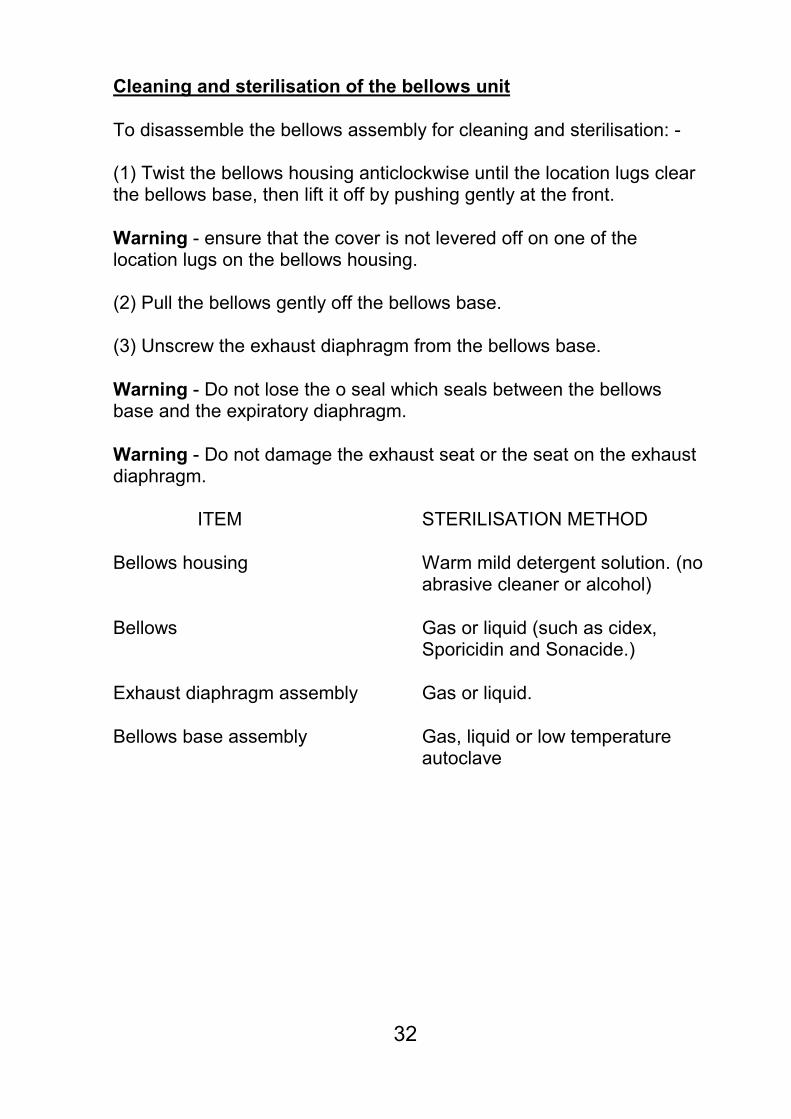
To disassemble the bellows assembly for cleaning and sterilisation: - (1) Twist the bellows housing anticlockwise until the location lugs clear the bellows base, then lift it off by pushing gently at the front.
Warning - ensure that the cover is not levered off on one of the location lugs on the bellows housing. (2) Pull the bellows gently off the bellows base. (3) Unscrew the exhaust diaphragm from the bellows base.
Warning - Do not lose the o seal which seals between the bellows base and the expiratory diaphragm.
Warning - Do not damage the exhaust seat or the seat on the exhaust diaphragm. ITEM STERILISATION METHOD
Bellows housing Warm mild detergent solution. (no
abrasive cleaner or alcohol)
Bellows Gas or liquid (such as cidex,
Sporicidin and Sonacide.)
Exhaust diaphragm assembly Gas or liquid.
Bellows base assembly Gas, liquid or low temperature
autoclave

33
Ordering information 9050-200 OES CARINA anaesthesia ventilator. 9060-001 1.5 metre oxygen drive hose - DISS to open end. 9060-010 Corrugated drive gas hose - 265 mm 9060-011 Corrugated drive gas hose - 1500 mm (for remote mounting of the bellows) 9060-012 Patient breathing system drive hose -1800 mm 9060-020 Breathing system pressure tee - piece - 22 mm male / female taper 9060-015 Pressure sensing tube - silicone 2.5 metres. 9070-001 Adult bellows assembly. 9070-002 Adult bellows housing. 9070-003 Adult bellows. 9070-004 Exhaust diaphragm assembly. 9070-005 Exhaust diaphragm assembly screws - 3 off. 9070-006 Bellows base assembly. 9070-007 Bellows base thumb screws - 4 off. 9050-005 Pole mount bracket. 0000-000 ASTRA anaesthesia machine dovetail bracket.

34
User notes