Embed Size (px)
Citation preview
Houston, S. L.; Houston, W. N. and Padilla, J. M. (1987). Microcomputer-Aided Evaluation of Earthquake-Induced Permanent Slope Displacements. Microcomputers in Civil Engineering, p.p. 207-222.
1
MICROCOMPUTER-AIDED EVALUATION OF EARTHQUAKE-INDUCED
PERMANENT SLOPE DISPLACEMENTS
Sandra L. Houston, William N. Houston, and Manuel Padilla.
Arizona State University
A Geotechnical engineering microcomputer program has been developed for the
determination of permanent slope displacements resulting from earthquake shaking. The
Newmark procedure, in which accelerations in excess of yield accelerations are double
integrated to obtain displacements, has been incorporated into the program DISPLMT.
Several user options are available for describing the yield acceleration function, including
variation with time and variation with displacement. Screen graphics are available which
allow the user to observe the down slope movements of the Newmark sliding block as they
increase with time during the simulated earthquake. DISPLMT has been used to calculate
the permanent movements of an earth dam using acceleration-time histories and soil shear
stresses determined from a separate analysis. Modification to the conventional Newmark
procedure, by introduction or a “slip layer” has been made in the analysis of a dam.
Permanent slope displacements can be analyzed using the recommended procedure, which
involves fairly simple computations that can be performed in a reasonable period of time
with the exclusive use of microcomputers.
INTRODUCTION
Approximately four methods of assessing seismic slope stability are currently being
used be or are under study. The most ideal of these analyses is a two or three dimensional
finite-element analysis which employs a complex general constitutive model which is
capable of quantifying both elastic recoverable and plastic permanent strains. The output
from such an analysis includes stresses and strains as a function of time, displacement
versus time, and a description of the final deformed shape of the slope. Although recent
research activities have been devoted to development of such an analysis [ ]2,6 , it requires
considerable run time on a mainframe computer, and it is probably beyond the state-of-the-
practice at the present time.

Houston, S. L.; Houston, W. N. and Padilla, J. M. (1987). Microcomputer-Aided Evaluation of Earthquake-Induced Permanent Slope Displacements. Microcomputers in Civil Engineering, p.p. 207-222.
2
The most simplified approach would be a pseudo static analysis, in which an
“equivalent” static force is applied to the slope, and a factor of safety is determined. This
type of analysis provides no information on permanent movements, which is one of the
most important pieces of information in assessing the safety of an embankment or earth
dam against earthquake shaking. Another technique which has been used recently is to
perform a static analysis “after the earthquake” using post-earthquake shear strengths,
which are less than static strength values [ ]1 . This method also provides no information on
the permanent slope displacements due to ground shaking.
Probably the most frequently used technique for computing earthquake-induced
slope displacements is the Newmark method of double integration of the “excess”
accelerations [ ]3 . The assumption is made that only the permanent strains are of interest or
that all strains which occur prior to the point when the dynamic stress equals the dynamic
strength of the soil are negligible.
First, the slope is modeled using the sliding block analogy as shown in Figure 1.
When the acceleration of the block is such that the frictional sliding resistance is just
overcome, the factor of safety against sliding equals one, and the acceleration is said to
equal the yield acceleration, ya . They corresponding point for the real slope is when the
acceleration is just large enough to drive the factor of safety to one. Using a slope stability
program which employs seismic coefficients, the coefficient which brings the factor of
safety to one can be determined. This coefficient is the yield acceleration. A dynamic
response analysis is then performed, and the acceleration-time histories at points along the
“critical slip surface” are determined. A representative time history is typically scaled so
that the maximum acceleration is equal to the average value of several points along the
potential slip surface. The accelerations in excess of the yield acceleration are then double
integrated to get displacements.

Houston, S. L.; Houston, W. N. and Padilla, J. M. (1987). Microcomputer-Aided Evaluation of Earthquake-Induced Permanent Slope Displacements. Microcomputers in Civil Engineering, p.p. 207-222.
3
Figure 1. The sliding block analogy.
Microcomputer slope stability programs are available which can be used to obtain
the seismic coefficient required to bring the slope to a factor of safety of one. Acceleration-
time histories which are representative for the slope can be obtained using a two-
dimensional finite-element analysis, or approximated using a series of one-dimensional site
response analyses. Microcomputer programs for one-dimensional site response analyses are
also available. Of course, if the site response analysis is sufficiently complex and complete
so as to include permanent strains as output, the Newmark method would not be required.
Probably the most commonly used program for the site response analysis is a wave
propagation program called SHAKE [ ]7 , which does not provide permanent strains as
output.
DISPLMT, developed as a part of this study, can be used to perform the double
integration of the accelerations in excess of the yield acceleration. Thus, the evaluation of
the permanent slope displacement resulting from earthquake shaking can be made using
only microcomputer computations and the relatively simple procedure described below.
RECOMMENDED PROCEDURE
When the “sliding block on an inclined plane” analogy is applied to a potential
landslide, as depicted in Figure 2, a number of difficulties arise. First, the slip surface
(shear zone) may be curved rather than planar. However, the problems to which this
analogy are usually applied typically involve slip surfaces without severe curvature and
with relatively gentle slopes, which may be represented by a noncircular slip surface as
shown in Figure 2.

Houston, S. L.; Houston, W. N. and Padilla, J. M. (1987). Microcomputer-Aided Evaluation of Earthquake-Induced Permanent Slope Displacements. Microcomputers in Civil Engineering, p.p. 207-222.
4
Secondly, the block and the base are both rigid, whereas neither the sliding wedge
nor the material below it in Figure 2 are rigid. The lack of rigidity in the real soil profile
comes into play when the dynamic response of the soil column to an earthquake is
calculated [ ]3 . This calculation will be discussed shortly. First however, the computation of
the static factor of safety, staticFS , and the yield acceleration, ya , for the sliding wedge in
Figure 2 will be addressed.
Figure 2. Typical slope failure to which block analogy is applied.
The static factor of safety is defined as the ratio of the maximum available shearing
resistance between base and block to the shearing resistance between base and block
required for equilibrium when the base is not shaking. If this static factor of safety is
greater than one, then the block does not slide for “static” conditions.
The yield acceleration is computed by performing a pseudo-static slope stability
analysis in which the entire sliding wedge is indeed assumed to be rigid - or at least the
“slices” are assumed rigid. Each and every slice is assumed to experience the same
acceleration at the same time. This inertial force is added vectorially to the gravitational
forces and the factor of safety is computed. The acceleration applied to all slices is varied
by trial, and error until the computed factor of safety is one. The corresponding acceleration
is ya . In general, ya would not be constant, but would vary with time or displacement. This
is because the shearing resistance of the soil, which relates directly to ya , may decrease

Houston, S. L.; Houston, W. N. and Padilla, J. M. (1987). Microcomputer-Aided Evaluation of Earthquake-Induced Permanent Slope Displacements. Microcomputers in Civil Engineering, p.p. 207-222.
5
with time due to the damaging effects of the shaking. The yield acceleration is likely to
begin at the value of ya corresponding to the static soil strength, and end with the value of
ya corresponding to the post-earthquakes strength. Alternatively, it would be reasonable to
allow variation of the yield acceleration as a function of displacement. Both of these
options, as well as constant yield acceleration, can be selected in DISPLMT.
Usually, only the downslope value of ya is computed. However, the upslope
component is also required for this analysis of permanent slope movements. The upslope
component of ya can be computed using the static factor of safety and the downslope
component of ya , i.e.,
staticMRFSSR
=
( )y downslope
MR SRam−
=
( )y upnslope
MR SRam+
=
Where,
MR = Maximum available shearing resistance
SR = Shearing Resistance needed for static equilibrium
m = Mass of the block
Upon rearranging and combining these three equations, it can be found that the ratio
of the downslope value to the upslope value of ya is equal to:
( )( )
11
static
static
FSFS
−+
The dynamic response of the soil slope to an earthquake motion imposed at
“bedrock” (point R in Figure 2) can best be computed by a two-dimensional finite-element
Houston, S. L.; Houston, W. N. and Padilla, J. M. (1987). Microcomputer-Aided Evaluation of Earthquake-Induced Permanent Slope Displacements. Microcomputers in Civil Engineering, p.p. 207-222.
6
analysis. A number of comparisons have shown, however, that a satisfactory approximation
can be obtained by using one-dimensional wave propagation programs [ ]7,9 .
A series of three profiles are analyzed, one near the crest, one near the center, and
one near the toe of the potential sliding wedge. Examples are shown as profiles 1, 2, and 3
in Figure 2. The results are then averaged in order to obtain a response which is quite close
to the average response that would have been obtained from a two-dimensional finite-
element in term of acceleration-time history. The input motion at point R propagate
upward toward points A , 3B , 2B , and 1B . Trey may be ether amplified or attenuated, but
they are, in general, modified as they propagate upward.
For typical earthquakes and typical soil profiles, the elastic strains are moderately
small and the computed maximum accelerations at point 1B , 2B , and 3B in Figure 2 will
often exceed ya . In fact, if these acceleration did not exceed ya , then no problem with
seismic stability would exist. As cited earlier, a problem does arise when the calculated
accelerations exceed ya . In the “sliding block on an inclined plane” model that is being
utilized, the acceleration in the block or the sliding wedge can never exceed ya because
movements would occur. Therefore, computed accelerations above ya in the sliding wedge
are inconsistent with the model being employed.
In order to avoid this inconsistency, it is necessary to introduce a “slip layer” with
“softened” properties at the location of the shear zone. The properties of the “slip layer” are
varied by trial and error until the average maximum acceleration at points 1B , 2B , and 3B is
approximately equal to ya . When this convergence is achieved, then the corresponding
acceleration-time history at point A (just below the “slip layer”) can be compared to ya
and the “excess” accelerations double integrated to obtain a permanent movement estimate
for profile 2, in Figure 2. Without the introduction of such a slip layer, dynamic response
programs, such as SHAKE, would predict accelerations within the sliding mass which are
in excess of the yield acceleration. Perhaps more importantly, the acceleration-time history
Houston, S. L.; Houston, W. N. and Padilla, J. M. (1987). Microcomputer-Aided Evaluation of Earthquake-Induced Permanent Slope Displacements. Microcomputers in Civil Engineering, p.p. 207-222.
7
at point A may depend somewhat on whether or not a “slip layer” that prevents the
acceleration of the block from exceeding ya is present. This is because the acceleration-
time history at any point will depend on how much energy is being dissipated in the
vicinity of the point. Therefore, in order to get the best estimate of the acceleration-time
history at point A (when maxa within the wedge is essentially equal to ya ) the “slip layer”
should be present.
Similar movement estimates can be made for profiles 1 and 3 and then an average
movement can be calculated. Although the average is probably the “best estimate”, the
average as well as the maximum should be reported. These movement computations can
readily be made with a computer program such as DISPLMT.
It should be noted that the sliding block model does not apply perfectly to the
landslide problem. In fact, in view of the various approximations required, it probably
should be viewed as a tool to assist the engineer in deciding whether the probable slope
movement is: (l) a fraction of an inch, or (2) a few inches, or (3) a few feet. This level of
distinction is usually adequate to enable an engineering or management decision. The
computational method cannot be used to realistically distinguish between 0.33 feet and 0.57
feet, for example. However, such a distinction is often made during the analysis stage in
order to evaluate parameter sensitivity.
PROGRAM DISPLMT
DISPLMT is a FORTRAN microcomputer program which calculates permanent
slope displacements resulting from earthquake shaking. The Newmark method, in which
accelerations in excess of yield accelerations are double integrated to obtain displacements,
has been incorporated into DISPLMT. The inputs to the program are the static factor of
safety, the yield acceleration, and the acceleration-time history at the point along the slip
surface which is being evaluated. Three options for specifying the yield acceleration
function are available to the user:
Houston, S. L.; Houston, W. N. and Padilla, J. M. (1987). Microcomputer-Aided Evaluation of Earthquake-Induced Permanent Slope Displacements. Microcomputers in Civil Engineering, p.p. 207-222.
8
1. Constant yield acceleration throughout the earthquake.
2. A yield acceleration function which varies as a function of time. The variation is
prescribed by the user.
3. A yield acceleration function which varies as a function of the computed permanent
displacement. The variation is prescribed by the user.
Program outputs consist of a table of the maximum velocity and final permanent
displacement or a table containing the entire velocity and displacement history. In addition,
screen graphics are available which allow the user to observe the movement of the sliding
block as it progresses throughout the computation. Also plotted are the acceleration-time
history and the yield acceleration versus time. Screen graphics have been accomplished
using a graphics kernel software package, which is a set of subroutines written in assembly
language that can be called from FORTRAN. A listing of the program, which includes
general input instructions, has been included in Appendix II to this paper.
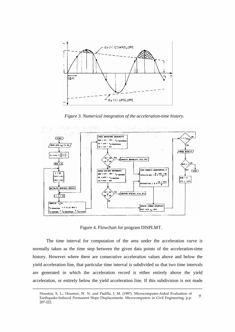
The “excess” accelerations are double integrated in DISPLMT to obtain the
permanent displacement of the slope. Figure 3 shows a sketch of a yield function which
varies linearly with time from the computed yield acceleration. using pre-earthquake soil
strength parameters, to the yield acceleration computed using post-earthquake soil strength
parameters. The trapezoidal method, a simple numerical integration scheme, is used to
perform the integration. The interval from the initial time of zero to the desired final time,
ft , is subdivided and the areas of the trapezoids (shown in Figure 3) are summed to obtain
an estimate of the area under the “excess” acceleration curve. Only the contributions to the
integral which fall above the yield acceleration line are included in the summation. The
corresponding velocity curve is then integrated using the trapezoidal rule to obtain an
estimate of the permanent slope displacements. The error in the computation described
above is, of course, reduced by decreasing the time step used in describing the acceleration-
time record.
Houston, S. L.; Houston, W. N. and Padilla, J. M. (1987). Microcomputer-Aided Evaluation of Earthquake-Induced Permanent Slope Displacements. Microcomputers in Civil Engineering, p.p. 207-222.
9
Figure 3. Numerical integration of the acceleration-time history.
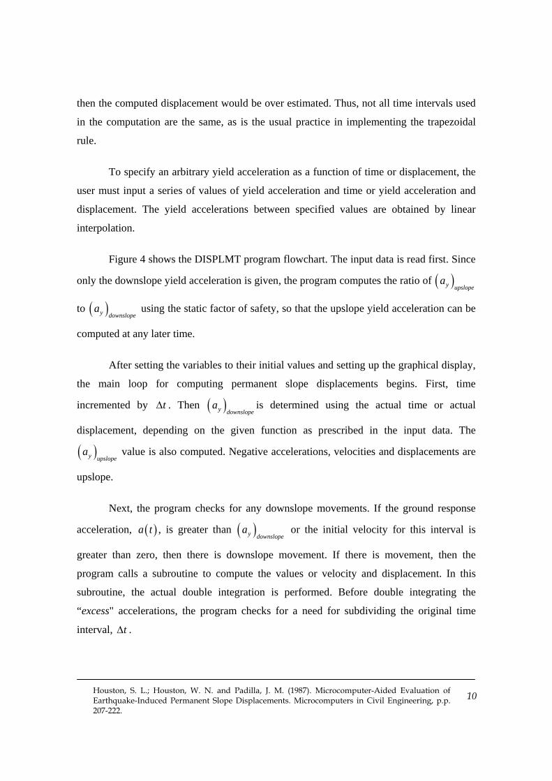
Figure 4. Flowchart for program DISPLMT.
The time interval for computation of the area under the acceleration curve is
normally taken as the time step between the given data points of the acceleration-time
history. However where there are consecutive acceleration values above and below the
yield acceleration line, that particular time interval is subdivided so that two time intervals
are generated in which the acceleration record is either entirely above the yield
acceleration, or entirely below the yield acceleration line. If this subdivision is not made
Houston, S. L.; Houston, W. N. and Padilla, J. M. (1987). Microcomputer-Aided Evaluation of Earthquake-Induced Permanent Slope Displacements. Microcomputers in Civil Engineering, p.p. 207-222.
10
then the computed displacement would be over estimated. Thus, not all time intervals used
in the computation are the same, as is the usual practice in implementing the trapezoidal
rule.
To specify an arbitrary yield acceleration as a function of time or displacement, the
user must input a series of values of yield acceleration and time or yield acceleration and
displacement. The yield accelerations between specified values are obtained by linear
interpolation.
Figure 4 shows the DISPLMT program flowchart. The input data is read first. Since
only the downslope yield acceleration is given, the program computes the ratio of ( )y upslopea
to ( )y downslopea using the static factor of safety, so that the upslope yield acceleration can be
computed at any later time.
After setting the variables to their initial values and setting up the graphical display,
the main loop for computing permanent slope displacements begins. First, time
incremented by t∆ . Then ( )y downslopea is determined using the actual time or actual
displacement, depending on the given function as prescribed in the input data. The
( )y upslopea value is also computed. Negative accelerations, velocities and displacements are
upslope.
Next, the program checks for any downslope movements. If the ground response
acceleration, ( )a t , is greater than ( )y downslopea or the initial velocity for this interval is
greater than zero, then there is downslope movement. If there is movement, then the
program calls a subroutine to compute the values or velocity and displacement. In this
subroutine, the actual double integration is performed. Before double integrating the
“excess" accelerations, the program checks for a need for subdividing the original time
interval, t∆ .
Houston, S. L.; Houston, W. N. and Padilla, J. M. (1987). Microcomputer-Aided Evaluation of Earthquake-Induced Permanent Slope Displacements. Microcomputers in Civil Engineering, p.p. 207-222.
11
If there is no downslope movement, then a check is made for upslope movement. If
the ground response acceleration, ( )a t , exceeds or ( )y upslopea or the initial velocity for this
interval is less than zero then there is an upslope movement. Again, if there is movement,
the program calls the subroutine to compute velocity and displacement.
At the end of this main loop, the graphic screen is updated with the new values or
displacement and accelerations. The analog block is moved to the new displaced value.
This is done by first erasing the block at its original position and then plotting it at the new
computed position. The original position or the block is shown in all cases by a dashed
outline. Time, t, is incremented by t∆ and the main loop is entered again.
When the final time is reached, the acceleration-time history is reversed by
changing the sign to each one or its values and the process previously described is
performed again for the reverse earthquake. This reversal is done in case the input
acceleration-time history is significantly and unsymmetrical.
It is generally assumed that both the first run and the reversal run are of equal
validity. The two runs are used to indicate the probable range in results.
IMPLEMENTATION OF RECOMMENDED PROCEDURE TO AN EARTH DAM
An existing earth dam was recently enlarged for the purposes of improving flood
control. The original earth dam was approximately 650 feet long at the crest and about 79
feet above the original ground surface. The enlargement raised the dam 8 feet in height.
The dam is located in a small valley with a 45 ft. layer of alluvium overlying bedrock. It is
in a region of seismic activity, in which several major earthquakes have occurred within
about 50 miles of the dam, ranging from a Richter magnitude of 8.3-5.8 over the past 80
years or so. Several major faults are located from 10 to 40 miles of the site, and several
small inactive faults and shear zones are present in the area near the dam
The recommended procedure, described in the previous sections, was used in
conjunction with the newly developed microcomputer program, DISPLMT, to estimate the
Houston, S. L.; Houston, W. N. and Padilla, J. M. (1987). Microcomputer-Aided Evaluation of Earthquake-Induced Permanent Slope Displacements. Microcomputers in Civil Engineering, p.p. 207-222.
12
permanent slope displacements of the earth dam using the Newmark method of double
integrating the excess accelerations. The critical noncircular slip surfaces which were
analyzed for the upstream and downstream slopes of the dam are shown in Figures 5 and 6
respectively.
The design earthquake for the seismic response computations was an 8.25 Richter
magnitude. Because there are no available measured records for earthquakes of this
magnitude, the synthetic “Seed-Idriss” record was used as the input motion.
DOWNSTREAM SLOPE ANALYSIS
The critical slip surface for the downstream slope and static loading conditions, as
shown in Figure 5, was noncircular. The static factor of safety of 1.37 was determined
using the Morgenstern and Price method and the microcomputer program TSLOPE [ ]10 .
The yield acceleration, using pre-earthquake soil parameters, was also determined using the
pseudo-static method in TSLOPE. The yield acceleration for the critical slip surface was
0.14 g, which was assumed to remain constant throughout the earthquake shaking. The
yield acceleration is computed as the acceleration which brings the slope to a factor of
safety of 1.0.
The procedure used in the computation of permanent slope displacement utilizes
one-dimensional seismic response analyses to obtain the acceleration-time histories which
are input into DISPLMT. The “average” acceleration-time history from the one-
dimensional analysis, which can be obtained using microcomputer versions of programs
such as SHAKE, is typically very close to that which is obtained using the more complex
two-dimensional site response analyses performed using finite-element programs on a
mainframe computer. This has been verified by the authors for several different soil profiles
and slope geometry.

Houston, S. L.; Houston, W. N. and Padilla, J. M. (1987). Microcomputer-Aided Evaluation of Earthquake-Induced Permanent Slope Displacements. Microcomputers in Civil Engineering, p.p. 207-222.
13
Figure 5. Critical downstream slip surface.
Figure 6. Critical upstream slip surface.

Houston, S. L.; Houston, W. N. and Padilla, J. M. (1987). Microcomputer-Aided Evaluation of Earthquake-Induced Permanent Slope Displacements. Microcomputers in Civil Engineering, p.p. 207-222.
14
In the analysis of the downstream slope of the earth dam, acceleration-time histories
were computed for several soil profiles within the sliding mass. Acceleration-time histories
were obtained for vertical soil profiles corresponding to slices 1, 5, and 10, shown in Figure
5. According to the recommended procedure, discussed previously, a “softened layer” was
introduced at the elevation corresponding to the critical slip surface in performing the
seismic response computations. The acceleration-time histories for points immediately
below the shear zone were then input into DISPLMT for the purposes of computing
permanent displacements. Acceleration-time histories were obtained at the three sections
along the slope using SHAKE, which incorporated an equivalent linear soil modulus.
Using the constant yield acceleration assumption, the permanent slope
displacements were estimated using DISPLMT. For the soil profile corresponding to slice 1
of the downstream slope, the maximum permanent deformation was 0.07 ft. downslope.
The maximum acceleration in the acceleration-time history for slice 1 was 0.253 g. The
middle of the slope, slice number 5, resulted in a maximum downslope movement of 0.27
ft. for a maximum acceleration of 0.328 g. The profile at the bottom of the slope, slice 10,
resulted in a maximum downslope movement of 0.85 ft. for a maximum acceleration of
0.437 g.
The average value of the permanent downslope displacement for the three profiles is
probably the best estimate for the slope, because the rigid block assumption require that the
displacements be equal for the entire slope. Therefore, the average permanent downslope
displacement for the downstream slope of the earth dam was estimated to be about 0.3 ft.
However, it is considered good practice to report the maximum calculated value as well.
The graphical output from program is shown in Figure 7 for the slope downstream
slope computation for the profile corresponding to slice 5 in the center of the critical sliding
mass. An interval of the acceleration-time history and the yield acceleration as a function of
time are shown along with the “moving block” in the output.

Houston, S. L.; Houston, W. N. and Padilla, J. M. (1987). Microcomputer-Aided Evaluation of Earthquake-Induced Permanent Slope Displacements. Microcomputers in Civil Engineering, p.p. 207-222.
15
Figure 7. Graphical output from DISPLMT showing downstream slope movement.
UPSTREAM SLOPE ANALYSES
A static slope stability analysis was performed on the upstream slope of the dam
using the microcomputer program TSLOPE. The static factor of safety was found to be
2.17 to the critical noncircular slip surface, and the yield acceleration, using pre-earthquake
strength values, was found to be 0.25 g.
Acceleration-time histories were computed to several soil profiles within the sliding
mass. In the upstream slope analysis, profiles corresponding to slice number 1, 8, and 14,
shown in Figure 6, were used in the one-dimensional site response computation to
determine the range of acceleration-time histories for the slope. In performing the one-
dimensional seismic analyses, a softened layer was introduced in the vicinity of the
“critical” slip surface. Using the recommended procedure, the acceleration-time histories
for points immediately below the slip surface were used to obtain “representative”
acceleration-time histories for input into DISPLMT.
A constant yield acceleration was assumed for the DISPLMT computations for the
each dam. For the soil profile corresponding to slice 8, the maximum downslope
deformation was 0.035 ft. For slices 1 and 14, the maximum accelerations computed from
the one-dimensional seismic analysis did not exceed the yield acceleration (0.246 g.), and
therefore no displacements were computed.
Houston, S. L.; Houston, W. N. and Padilla, J. M. (1987). Microcomputer-Aided Evaluation of Earthquake-Induced Permanent Slope Displacements. Microcomputers in Civil Engineering, p.p. 207-222.
16
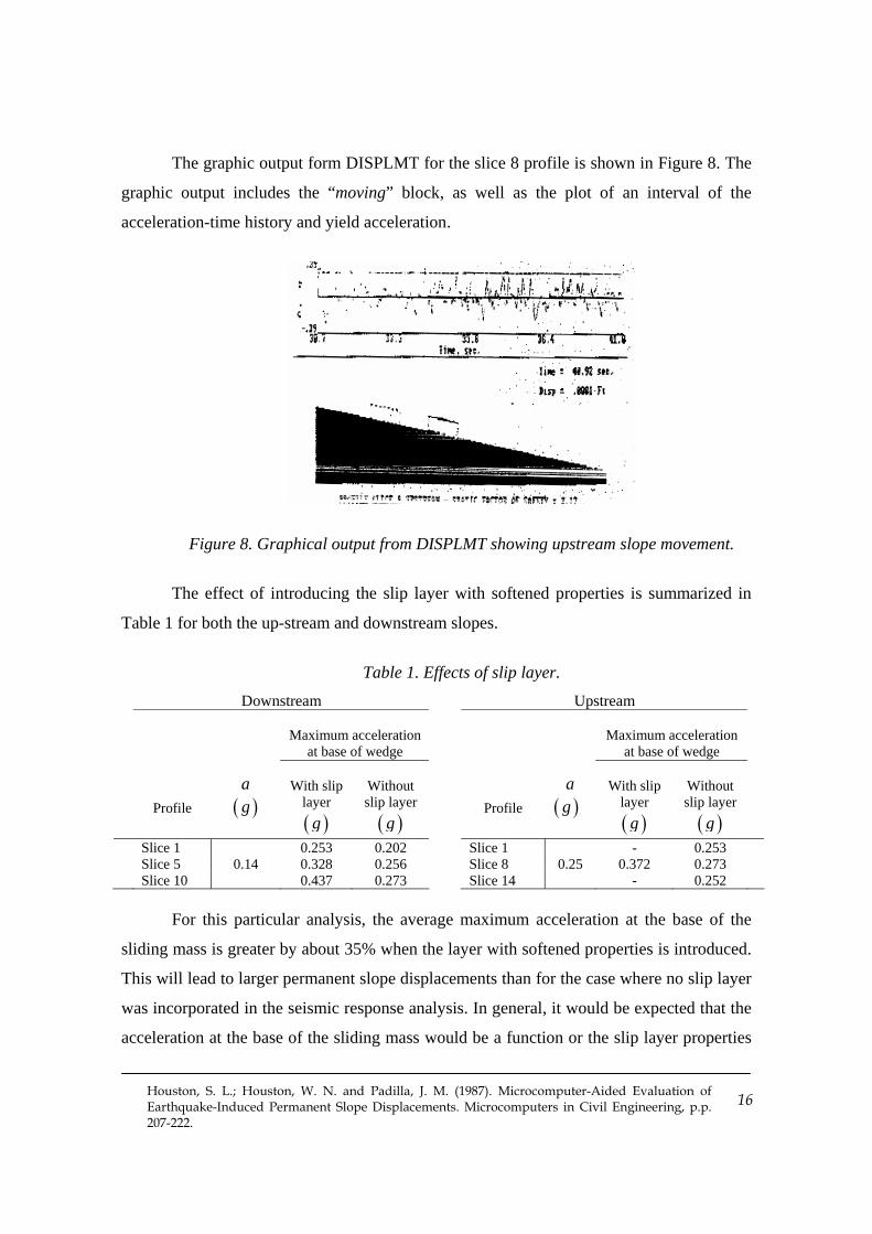
The graphic output form DISPLMT for the slice 8 profile is shown in Figure 8. The
graphic output includes the “moving” block, as well as the plot of an interval of the
acceleration-time history and yield acceleration.
Figure 8. Graphical output from DISPLMT showing upstream slope movement.
The effect of introducing the slip layer with softened properties is summarized in
Table 1 for both the up-stream and downstream slopes.
Table 1. Effects of slip layer. Downstream Upstream
Maximum acceleration at base of wedge
Maximum acceleration at base of wedge
Profile a
( )g With slip
layer ( )g
Without slip layer ( )g
Profile
a
( )g With slip
layer ( )g
Without slip layer ( )g
Slice 1 0.253 0.202 Slice 1 - 0.253 Slice 5 0.14 0.328 0.256 Slice 8 0.25 0.372 0.273 Slice 10 0.437 0.273 Slice 14 - 0.252
For this particular analysis, the average maximum acceleration at the base of the
sliding mass is greater by about 35% when the layer with softened properties is introduced.
This will lead to larger permanent slope displacements than for the case where no slip layer
was incorporated in the seismic response analysis. In general, it would be expected that the
acceleration at the base of the sliding mass would be a function or the slip layer properties

Houston, S. L.; Houston, W. N. and Padilla, J. M. (1987). Microcomputer-Aided Evaluation of Earthquake-Induced Permanent Slope Displacements. Microcomputers in Civil Engineering, p.p. 207-222.
17
because the dissipation of energy and the amount of strain depend on the slip layer
properties. The 35% increase in maximum acceleration observed is for this particular earth
dam, and the difference in acceleration with and without the slip layer would be dependent
upon the particular soil profile under study.
SUMMARY
Modifications to the conventional Newmark sliding block procedure for the
determination of permanent slope displacements resulting from earthquake shaking were
presented. Following the recommended procedure for estimating permanent slope
displacements, the entire analysis can be performed with microcomputer facilities alone.
The proposed method introduces a layer with softened properties at the location of the shear
zone for the computation of the seismic ground response. This “slip layer” prevents the
calculated accelerations within the slope from exceeding the yield acceleration, a condition
which is inconsistent with the sliding block analogy. The computed seismic ground
acceleration-time response just below the slip layer acceleration is then double Integrated to
obtain the permanent displacements of the slope.
A microcomputer program has been developed to double integrate the seismic
ground response for determining the permanent slope displacements. The program allows
the yield acceleration to be a function of time or displacement. Graphical output from the
computer program DISPLMT allows the user to observe the downslope movements of the
sliding block as they increase each time the yield acceleration is exceeded.
The recommended procedure was used to estimate the permanent slope
displacements of an earth dam. A one-dimensional microcomputer analysis using an
equivalent linear soil model was used for computing the acceleration-time history at three
representative profiles along the slope. DISPLMT was then used to calculate the permanent
downslope movements.
Houston, S. L.; Houston, W. N. and Padilla, J. M. (1987). Microcomputer-Aided Evaluation of Earthquake-Induced Permanent Slope Displacements. Microcomputers in Civil Engineering, p.p. 207-222.
18
REFERENCES
[ ]1 Castro, G., Poulos, S. J., and Leathers, F. D. A Re-examination of the Slide of the
Lower San Fernando Dam. Journal of Geotechnical Engineering, 3(9): 1093-1107
(1985).
[ ]2 Daddazio, R. P., Ettouney, M. M., and Sandler, I. S. Nonlinear Dynamic Slope
Stability Analysis. Journal of Geotechnical Engineering, 113(SM3): 285-298
(1987).
[ ]3 Lin, J. S. and Whitman, R. V. Earthquake Induced Displacement of Sliding blocks.
Journal of Geotechnical Engineering, 112(1): 44-59 (1986).
[ ]4 Makdisi, F. I. and Seed, H. B. Simplified Procedure for Estimating Dam and
Embankment Earthquake-Induced Deformations. Journal of Geotechnical
Engineering, 104(GT7): 849-867 (1978).
[ ]5 Newmark. N. M. Effects of Earthquakes on Dams and Embankments.
Geotechnique, 15(2): 139-160 (1965).
[ ]6 Prevost , J. H., Abdel-Ghaffar, A. M. and Lacy, S. J. Nonlinear Dynamic Analyses
of an Earth Dam. Journal of Geotechnical Engineering, 111(2): 882-897 (1985).
[ ]7 Schnabel, P. B., Lysmer, J., and Seed, H. B. Shake - A Computer Program For
Earthquake Response Analysis Of Horizontally Layered Soils. Report No. EERC
72-12. University of California, Berkeley, December 1972.
[ ]8 Seed, H. B. and Martin, G. R. The Seismic Coefficient in Earth Dam Design.
Journal of the Soil Mechanics and Foundations Division, 92(SM3): 25-58 (1966).
[ ]9 TESS1 – A Computer program for nonlinear ground response analyses. TAGA
Engineering Software Services. Berkeley, California, 1985.
[ ]10 TSLOPE – Computer program for limit equilibrium slope stability analysis. TAGA
Engineering Software Services, Berkeley, California, 1984.

Houston, S. L.; Houston, W. N. and Padilla, J. M. (1987). Microcomputer-Aided Evaluation of Earthquake-Induced Permanent Slope Displacements. Microcomputers in Civil Engineering, p.p. 207-222.
19
APPENDIX I – NOTATION
a = Acceleration
ya = Yield acceleration
( )a t = Acceleration-time history
FS = Factor of safety
p′ = Effective vertical stress
uS = Undrained shear strength
t∆ = Time incremental
φ = Friction angle