Embed Size (px)
Citation preview
1918 IEEE TRANSACTIONS ON POWER DELIVERY, VOL. 29, NO. 4, AUGUST 2014
Analysis, Modeling, and Simulation of thePhase-Hop Condition in Transformers:
The Largest Inrush CurrentsAshkan Farazmand, Francisco de León, Senior Member, IEEE, Kuang Zhang, Student Member, IEEE, and
Saeed Jazebi, Student Member, IEEE
Abstract—Inrush currents in transformers can have very dis-ruptive effects, such as voltage sags, false tripping of the protectivedevices, and mechanical stresses in the transformer windings.This paper shows that there are operating situations that maycause a transformer to draw abnormally high inrush currents.Examples include the normal operation of offline uninterruptiblepower-supply (UPS) systems, interruptions, voltage sags, andnotching. These conditions may produce inrush-like currentsof more than twice the value of the “normal” maximum inrushcaused by energizing at voltage zero-crossing. For this condition,the term “phase-hop” is used in this paper. Laboratory exper-iments were performed on four different transformers (1 kVA)with varied characteristics and show the impact of phase-hop inthe magnitude of inrush currents. The experiments are also usedto validate the Electromagnetic Transients Program model usedfor the analysis of multiple cases. In addition, the behavior of themagnetic flux in a transformer under phase-hop is investigatedand compared with different operating conditions using finite ele-ments. The results of this paper have implications in transformerdesign and in the operation and design of UPS systems to preventthe damaging effects of phase-hop.
Index Terms—Inrush currents, interruptions, phase-hop, trans-former modeling, uninterruptible power-supply (UPS) systems,voltage sags.
I. INTRODUCTION
P OWER-QUALITY (PQ) problems are critical issuesnowadays because of the increased use of power elec-
tronics loads. Interruptions and blackouts are the worst forms ofpower quality problems. Blackout is a complete loss of supplyvoltage or load current for longer than a minute [1]. Harmonics,interharmonics, power frequency variations, voltage unbal-ances, interruptions, notching, undervoltages, overvoltages,swells, noise, dc offset, voltage fluctuations, and voltage sagsare common power system operation phenomena which causePQ problems [2].
Manuscript received June 16, 2013; accepted October 08, 2013. Date of pub-lication February 17, 2014; date of current version July 21, 2014. This workwas supported by the U.S. Department of Energy under Grant DEOE0000072.Paper no. TPWRD-00680-2013.The authors are with the Department of Electrical and Computer Engineering,
Polytechnic University, Brooklyn, NY 11201 USA (e-mail: [email protected]; [email protected]; [email protected]; [email protected]).Color versions of one or more of the figures in this paper are available online
at http://ieeexplore.ieee.org.Digital Object Identifier 10.1109/TPWRD.2013.2286828
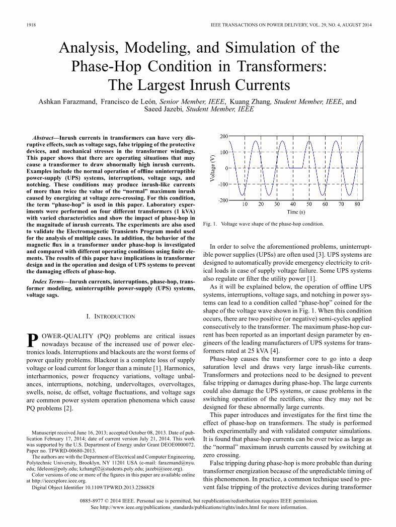
Fig. 1. Voltage wave shape of the phase-hop condition.
In order to solve the aforementioned problems, uninterrupt-ible power supplies (UPSs) are often used [3]. UPS systems aredesigned to automatically provide emergency electricity to crit-ical loads in case of supply voltage failure. Some UPS systemsalso regulate or filter the utility power [1].As it will be explained below, the operation of offline UPS
systems, interruptions, voltage sags, and notching in power sys-tems can lead to a condition called “phase-hop” coined for theshape of the voltage wave shown in Fig. 1. When this conditionoccurs, there are two positive (or negative) semi-cycles appliedconsecutively to the transformer. The maximum phase-hop cur-rent has been reported as an important design parameter by en-gineers of the leading manufacturers of UPS systems for trans-formers rated at 25 kVA [4].Phase-hop causes the transformer core to go into a deep
saturation level and draws very large inrush-like currents.Transformers and protections need to be designed to preventfalse tripping or damages during phase-hop. The large currentscould also damage the UPS systems, or cause problems in theswitching operation of the rectifiers, since they may not bedesigned for these abnormally large currents.This paper introduces and investigates for the first time the
effect of phase-hop on transformers. The study is performedboth experimentally and with validated computer simulations.It is found that phase-hop currents can be over twice as large asthe “normal” maximum inrush currents caused by switching atzero crossing.False tripping during phase-hop is more probable than during
transformer energization because of the unpredictable timing ofthis phenomenon. In practice, a common technique used to pre-vent false tripping of the protective devices during transformer
0885-8977 © 2014 IEEE. Personal use is permitted, but republication/redistribution requires IEEE permission.See http://www.ieee.org/publications_standards/publications/rights/index.html for more information.

FARAZMAND et al.: ANALYSIS, MODELING AND SIMULATION OF THE PHASE-HOP CONDITION IN TRANSFORMERS 1919
energization is to add a time delay. However, the occurrence ofphase-hop is not predictable and a delay cannot be applied.The correct estimation of phase-hop currents is important for
power system design. Inasmuch as their quantification is vitalfor UPS operation and design since UPS systems are preciselyused to provide backup power, therefore false tripping of vitalloads could be disastrous.
II. EFFECTS ON TRANSFORMER INRUSH CURRENTS OF POWERSYSTEM ELECTROMAGNETIC PHENOMENA
The variation of the rms voltage from its nominal value is de-scribed by two parameters: the magnitude of the voltage changeand its duration. Power system electromagnetic phenomena areclassified in four main groups based on the duration of the dis-turbance: steady state variations, long duration variations, shortduration variations, and transients [2].This section discusses how interruptions, voltage sags, and
notching in power systems can produce a phase-hop voltage tobe applied to transformers. In this section, it is assumed that aUPS system is not used to prevent these effects.
A. Interruptions
Interruptions are caused by transients that trigger utilitybreakers or switches to open. A voltage interruption occurswhen the supply voltage decreases to less than 10% of itsnominal value in one or more phase conductors. The causesfor this phenomenon are: faults, component failure, switching,false breaker tripping, and malfunction of control systems.Depending on the duration of interruptions, they are classified
in three types: momentary (0.5 cycle to 3 s), temporary (3 s to 1min), and sustained (greater than 1 min) [2]. The first two typesare short duration variations and the third is a long duration vari-ation. The duration of the interruption depends on the reclosingcapability and speed of the protective device. Note that an in-terruption of exactly 0.5 cycle produces the phase-hop voltagewave shape illustrated in Fig. 1.
B. Voltage Sags
A voltage sag is a short duration decrease of the voltage be-tween 0.1 and 0.9 p.u. of the nominal voltage at the power fre-quency for durations of 0.5 cycle to 1 min [2]. The IEC wordfor this phenomenon is “dip” [5]. Sag durations are divided intothree categories: instantaneous (0.5 to 30 cycles), momentary(30 cycles to 3 s), and temporary (3 s to 1 min). The causesfor this phenomenon are system faults, switching of large loads,and starting of large motors [2]. Voltage sags cause a partialphase-hop, but currents can be larger than the “normal” inrush.
C. Notching
Notching is a repetitive steady state voltage disturbancelasting less than a half cycle. It represents a phenomenonthat is considered both a transient and a harmonic distortionsince it occurs continuously and the frequency componentsrelated to it are high [2]. It can occur in opposite polarity to themain waveform. In this case, it is subtracted from the normalwaveform. In an extreme case, notching may lead to a completeloss of voltage for up to a half cycle [3] corresponding to thephase-hop wave of Fig. 1.
Fig. 2. Off-line UPS performance when utility power is present (normal acpower mode).
Fig. 3. Offline UPS performance when there is over/undervoltage or powerloss (inverter mode).
Notching can be produced during the commutating actionfrom one phase to another in the normal operation of SCR-con-trolled equipment, such as three-phase converters, motor con-trols, and inverters. In this condition, a brief short circuit be-tween two phases occurs [3], [6].
III. UPS SYSTEMS
UPS systems are intended to provide constant and regulatedoutput voltage and power to critical loads regardless of powerquality disturbances present in the mains. The objective is toprevent voltage sags, power outages, impulses, noise, over-voltages or swells, harmonic distortions, frequency variations,voltage fluctuations, and voltage surges [7], [8].UPSs are classified into two groups: rotary and static. Rotary
UPSs normally use a diesel-fueled motor generator set and staticUPSs use battery as the backup power source [1]. Because thereare several technical problems with rotary UPS systems, most ofthe modern UPSs are static [1]. There are three kinds of UPSs:offline, line interactive, and online.
A. Offline (Standby) UPSDuring the time when the utility power is present, offline UPS
systems pass the power directly to the load; the load is not iso-lated from the mains. During this time, the battery backup isalso charged and the inverter connected to the battery is off (seeFig. 2).When the utility voltage is below a specified value or during
a utility power outage, the UPS turns on its internal dc ac in-verter to produce ac power from the battery. In this case, theequipment is connected to the inverter output mechanically (seeFig. 3).This method saves battery life by avoiding continuous
charging and discharging. However, as stated by most manu-facturers, there is a switch changeover time between 4 and 10ms to engage the UPS during an interruption [1]. Practically,this delay can be as long as 25 ms depending on the time thatit takes the UPS to detect the absence of utility voltage andtransfer to the battery. Therefore, during the changeover timethere is a voltage dropout to the connected equipment and thephase-hop condition is possible.
1920 IEEE TRANSACTIONS ON POWER DELIVERY, VOL. 29, NO. 4, AUGUST 2014
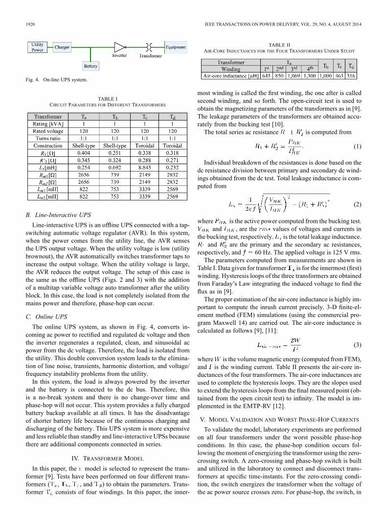
Fig. 4. On-line UPS system.
TABLE ICIRCUIT PARAMETERS FOR DIFFERENT TRANSFORMERS
B. Line-Interactive UPS
Line-interactive UPS is an offline UPS connected with a tap-switching automatic voltage regulator (AVR). In this system,when the power comes from the utility line, the AVR sensesthe UPS output voltage. When the utility voltage is low (utilitybrownout), the AVR automatically switches transformer taps toincrease the output voltage. When the utility voltage is large,the AVR reduces the output voltage. The setup of this case isthe same as the offline UPS (Figs. 2 and 3) with the additionof a multitap variable voltage auto transformer after the utilityblock. In this case, the load is not completely isolated from themains power and therefore, phase-hop can occur.
C. Online UPS
The online UPS system, as shown in Fig. 4, converts in-coming ac power to rectified and regulated dc voltage and thenthe inverter regenerates a regulated, clean, and sinusoidal acpower from the dc voltage. Therefore, the load is isolated fromthe utility. This double conversion system leads to the elimina-tion of line noise, transients, harmonic distortion, and voltage/frequency instability problems from the utility.In this system, the load is always powered by the inverter
and the battery is connected to the dc bus. Therefore, thisis a no-break system and there is no change-over time andphase-hop will not occur. This system provides a fully chargedbattery backup available at all times. It has the disadvantageof shorter battery life because of the continuous charging anddischarging of the battery. This UPS system is more expensiveand less reliable than standby and line-interactive UPSs becausethere are additional components connected in series.
IV. TRANSFORMER MODEL
In this paper, the model is selected to represent the trans-former [9]. Tests have been performed on four different trans-formers ( , , , and ) to obtain the parameters. Trans-former consists of four windings. In this paper, the inner-
TABLE IIAIR-CORE INDUCTANCES FOR THE FOUR TRANSFORMERS UNDER STUDY
most winding is called the first winding, the one after is calledsecond winding, and so forth. The open-circuit test is used toobtain the magnetizing parameters of the transformers as in [9].The leakage parameters of the transformers are obtained accu-rately from the bucking test [10].The total series ac resistance is computed from
(1)
Individual breakdown of the resistances is done based on thedc resistance division between primary and secondary dc wind-ings obtained from the dc test. Total leakage inductance is com-puted from
(2)
where is the active power computed from the bucking test.and , are the values of voltages and currents in
the bucking test, respectively. is the total leakage inductance.and are the primary and the secondary ac resistances,
respectively, and 60 Hz. The applied voltage is 125 V rms.The parameters computed from measurements are shown in
Table I. Data given for transformer is for the innermost (first)winding. Hysteresis loops of the three transformers are obtainedfrom Faraday’s Law integrating the induced voltage to find theflux as in [9].The proper estimation of the air-core inductance is highly im-
portant to compute the inrush current precisely. 3-D finite-el-ement method (FEM) simulations (using the commercial pro-gram Maxwell 14) are carried out. The air-core inductance iscalculated as follows [9], [11]:
(3)
where is the volumemagnetic energy (computed from FEM),and is the winding current. Table II presents the air-core in-ductances of the four transformers. The air-core inductances areused to complete the hysteresis loops. They are the slopes usedto extend the hysteresis loops from the final measured point (ob-tained from the open circuit test) to infinity. The model is im-plemented in the EMTP-RV [12].
V. MODEL VALIDATION AND WORST PHASE-HOP CURRENTS
To validate the model, laboratory experiments are performedon all four transformers under the worst possible phase-hopconditions. In this case, the phase-hop condition occurs fol-lowing themoment of energizing the transformer using the zero-crossing switch. A zero-crossing and phase-hop switch is builtand utilized in the laboratory to connect and disconnect trans-formers at specific time-instants. For the zero-crossing condi-tion, the switch energizes the transformer when the voltage ofthe ac power source crosses zero. For phase-hop, the switch, in
FARAZMAND et al.: ANALYSIS, MODELING AND SIMULATION OF THE PHASE-HOP CONDITION IN TRANSFORMERS 1921
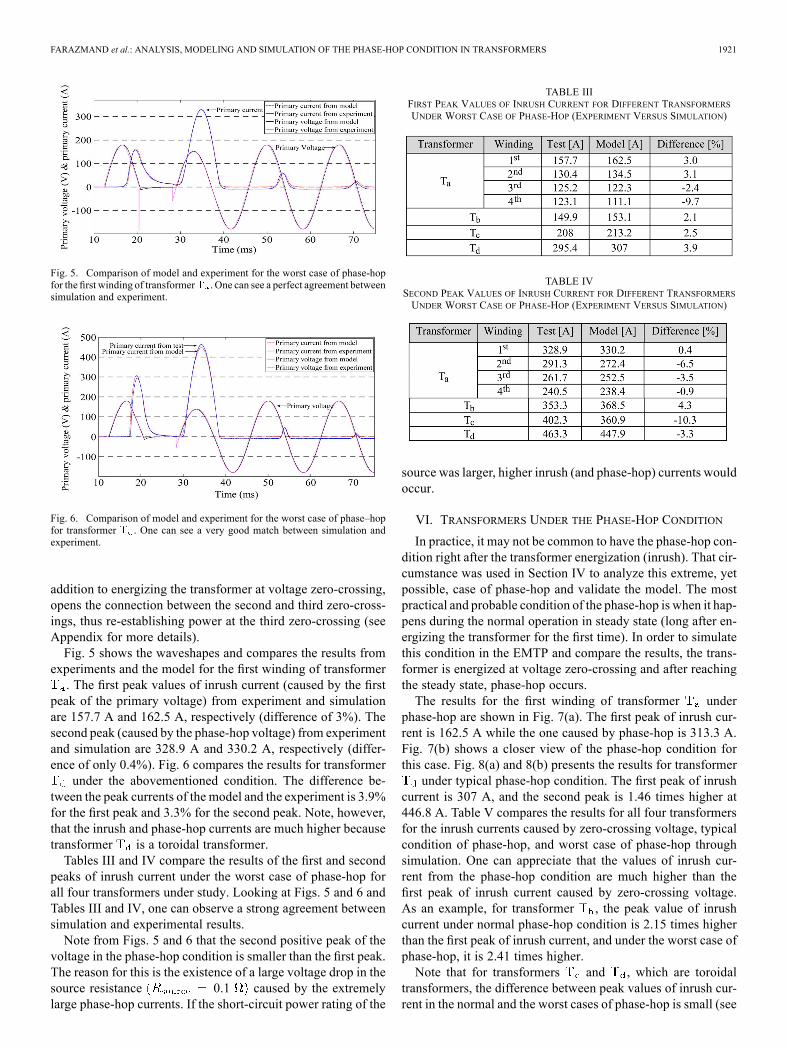
Fig. 5. Comparison of model and experiment for the worst case of phase-hopfor the first winding of transformer . One can see a perfect agreement betweensimulation and experiment.
Fig. 6. Comparison of model and experiment for the worst case of phase–hopfor transformer . One can see a very good match between simulation andexperiment.
addition to energizing the transformer at voltage zero-crossing,opens the connection between the second and third zero-cross-ings, thus re-establishing power at the third zero-crossing (seeAppendix for more details).Fig. 5 shows the waveshapes and compares the results from
experiments and the model for the first winding of transformer. The first peak values of inrush current (caused by the first
peak of the primary voltage) from experiment and simulationare 157.7 A and 162.5 A, respectively (difference of 3%). Thesecond peak (caused by the phase-hop voltage) from experimentand simulation are 328.9 A and 330.2 A, respectively (differ-ence of only 0.4%). Fig. 6 compares the results for transformer
under the abovementioned condition. The difference be-tween the peak currents of the model and the experiment is 3.9%for the first peak and 3.3% for the second peak. Note, however,that the inrush and phase-hop currents are much higher becausetransformer is a toroidal transformer.Tables III and IV compare the results of the first and second
peaks of inrush current under the worst case of phase-hop forall four transformers under study. Looking at Figs. 5 and 6 andTables III and IV, one can observe a strong agreement betweensimulation and experimental results.Note from Figs. 5 and 6 that the second positive peak of the
voltage in the phase-hop condition is smaller than the first peak.The reason for this is the existence of a large voltage drop in thesource resistance 0.1 caused by the extremelylarge phase-hop currents. If the short-circuit power rating of the
TABLE IIIFIRST PEAK VALUES OF INRUSH CURRENT FOR DIFFERENT TRANSFORMERSUNDER WORST CASE OF PHASE-HOP (EXPERIMENT VERSUS SIMULATION)
TABLE IVSECOND PEAK VALUES OF INRUSH CURRENT FOR DIFFERENT TRANSFORMERSUNDER WORST CASE OF PHASE-HOP (EXPERIMENT VERSUS SIMULATION)
source was larger, higher inrush (and phase-hop) currents wouldoccur.
VI. TRANSFORMERS UNDER THE PHASE-HOP CONDITION
In practice, it may not be common to have the phase-hop con-dition right after the transformer energization (inrush). That cir-cumstance was used in Section IV to analyze this extreme, yetpossible, case of phase-hop and validate the model. The mostpractical and probable condition of the phase-hop is when it hap-pens during the normal operation in steady state (long after en-ergizing the transformer for the first time). In order to simulatethis condition in the EMTP and compare the results, the trans-former is energized at voltage zero-crossing and after reachingthe steady state, phase-hop occurs.The results for the first winding of transformer under
phase-hop are shown in Fig. 7(a). The first peak of inrush cur-rent is 162.5 A while the one caused by phase-hop is 313.3 A.Fig. 7(b) shows a closer view of the phase-hop condition forthis case. Fig. 8(a) and 8(b) presents the results for transformerunder typical phase-hop condition. The first peak of inrush
current is 307 A, and the second peak is 1.46 times higher at446.8 A. Table V compares the results for all four transformersfor the inrush currents caused by zero-crossing voltage, typicalcondition of phase-hop, and worst case of phase-hop throughsimulation. One can appreciate that the values of inrush cur-rent from the phase-hop condition are much higher than thefirst peak of inrush current caused by zero-crossing voltage.As an example, for transformer , the peak value of inrushcurrent under normal phase-hop condition is 2.15 times higherthan the first peak of inrush current, and under the worst case ofphase-hop, it is 2.41 times higher.Note that for transformers and , which are toroidal
transformers, the difference between peak values of inrush cur-rent in the normal and the worst cases of phase-hop is small (see

1922 IEEE TRANSACTIONS ON POWER DELIVERY, VOL. 29, NO. 4, AUGUST 2014
Fig. 7. Simulation of transformer Ta (first winding) under the phase-hop con-dition. (a) Transient from the beginning of excitation. (b) Close view of thephase-hop part.
Fig. 8. Simulation of transformer under phase-hop condition. (a) Transientfrom the beginning of excitation. (b) Close view of the phase-hop part.
Table V). This is because in these transformers, the hysteresiscycles are thinner and flatter than the ones of standard trans-formers, because the cores have no gap. Therefore, under theworst case of phase-hop, the first spike of inrush current reachedzero at the start of the second peak, while for standard trans-formers ( and ), the second inrush current occurs whilethe current is not yet zero; see Figs. 5 and 6 to compare the re-sults for transformers and .
TABLE VCOMPARISON OF MAXIMUM INRUSH CURRENT UNDER DIFFERENT CONDITIONS
FOR DIFFERENT TRANSFORMERS
Fig. 9. Primary voltage and caused inrush current of the first winding of thetransformer Ta under 0% interruption.
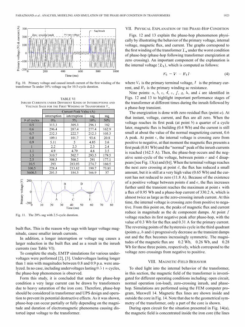
Fig. 9 shows the effect of the duration of an interruption onphase-hop current. The primary currents and the applied voltage(primary voltage) to the first winding of the transformer arepresented for a zero volts interruption lasting 0.5, 0.75, and 1cycle. One can see that the largest peak current is when the dura-tion of the interruption is half a cycle (313.3 A), which is almosttwice the normal zero-crossing inrush current (162.5 A). Underthis situation, a complete instance of phase-hop occurs. The casewith no inrush current is when the duration of the interruptionis one full cycle. This situation corresponds to the normal sinu-soidal condition since one complete cycle is eliminated. For aninterruption of 0.75 cycle, the peak current is 178.1 A.An example of a voltage sag is presented in Fig. 10. The pri-
mary voltage and inrush currents under zero-crossing and 10%voltage sag lasting for 10.5 cycle are shown, for the first windingof transformer . The value of inrush current caused by the sagis 274.7 A (69% larger than the zero-crossing inrush current).Table VI summarizes the inrush current results for 0% and 5%
interruptions, and for 10% and 50% voltage sags. The durationof the transient is between half a cycle (worst case) and 3600.5cycles (around 1 min). As shown in Table VI, the worst casesof inrush-like currents occur when the fault duration iscycles; where . This is so because there are twohalf cycles consecutively, which is the complete phase-hop. Incontrast, for sags lasting cycles, there is a small flux-can-cellation effect which decreasesmagnitude of the inrush current.To illustrate this, the 20% sag with 2.5-cycle duration 2)is depicted in Fig. 11. Note that the integral of the voltage is theflux. The areas A, B, C, and D cancel each other but the extrahalf cycle, E (highlighted in Fig. 11) leads to a decrease in the
FARAZMAND et al.: ANALYSIS, MODELING AND SIMULATION OF THE PHASE-HOP CONDITION IN TRANSFORMERS 1923
Fig. 10. Primary voltage and caused inrush current of the first winding of thetransformer Ta under 10% voltage sag for 10.5-cycle duration.
TABLE VIINRUSH CURRENTS UNDER DIFFERENT KINDS OF INTERRUPTIONS ANDVOLTAGE SAGS FOR THE FIRST WINDING OF TRANSFORMER
Fig. 11. The 20% sag with 2.5-cycle duration.
built flux. This is the reason why sags with larger voltage mag-nitude, cause smaller inrush currents.In addition, a longer interruption or voltage sag causes a
larger reduction in the built flux and as a result in the inrushcurrents (see Table VI).To complete the study, EMTP simulations for various under-
voltages were performed [2], [3]. Undervoltages lasting longerthan 1 min with magnitudes between 0.8 and 0.9 p.u. were ana-lyzed. In no case, including undervoltages lasting cycles,the phase-hop phenomenon is observed.Form this study, it is concluded that under the phase-hop
condition a very large current can be drawn by transformersdue to heavy saturation of the iron core. Therefore, phase-hopshould be considered in transformer and UPS design and opera-tion to prevent its potential destructive effects. As it was shown,phase-hop can occur partially or fully depending on the magni-tude and duration of electromagnetic phenomena causing dis-torted input voltage to the transformer.
VII. PHYSICAL EXPLANATION OF THE PHASE-HOP CONDITION
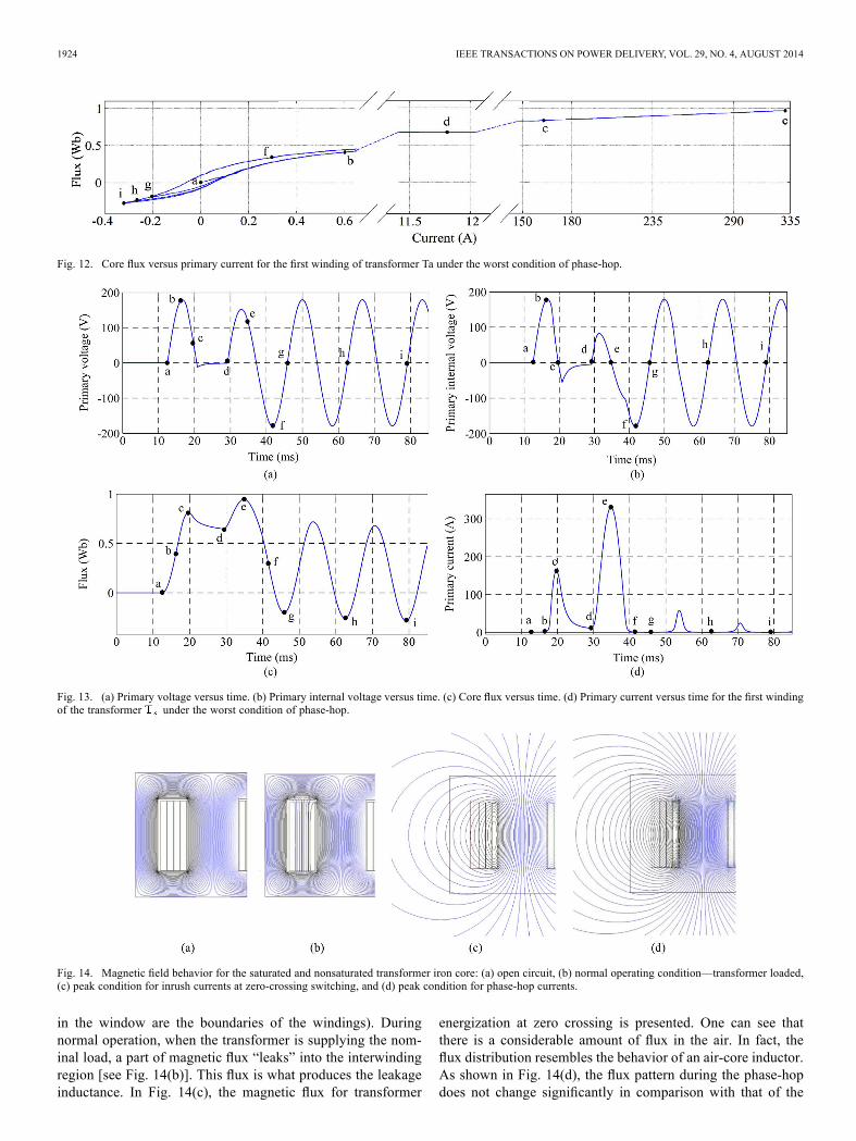
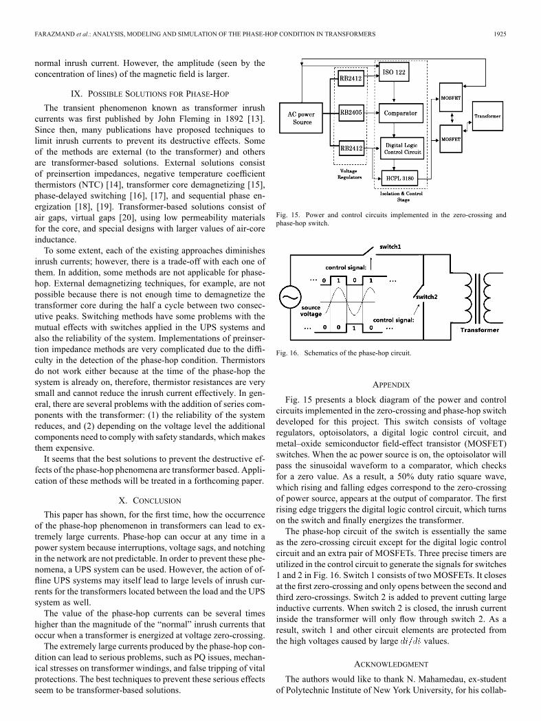
Figs. 12 and 13 explain the phase-hop phenomenon physi-cally by illustrating the behavior of the primary voltage, internalvoltage, magnetic flux, and current. The graphs correspond tothe first winding of the transformer under the worst conditionof phase-hop (phase-hop following transformer energization atzero crossing). An important component of the explanation isthe internal voltage , which is computed as follows:
(4)
where is the primary terminal voltage, is the primary cur-rent, and is the primary winding ac resistance.Nine points: , , , , , , , , and are identified in
Figs. 12 and 13 to highlight important performance stages ofthe transformer at different times during the inrush followed bya phase-hop transient.The energization is done with zero residual flux (point ). At
that instant, voltage, current, and flux are all zero. When thevoltage reaches its first peak (at point ) a quarter of a cyclelater, magnetic flux is building (0.4 Wb) and the current is stillsmall at about the value of the normal magnetizing current, 0.6A peak. At point , the internal voltage is crossing zero frompositive to negative, at that moment the magnetic flux presents afirst peak (0.81Wb) and the “normal” peak of the inrush currentsis reached (162.5 A). Then, the phase-hop occurs and the neg-ative semi-cycle of the voltage, between points and disap-pears [see Fig. 13(a) and (b)].When the terminal voltage reachesthe next zero crossing at point , the flux has reduced a smallamount, but it is still at a very high value (0.65 Wb) and the cur-rent has not reduced to zero (11.8 A). Because of the existenceof a positive voltage between points and , the flux increasesfurther until the transient reaches the maximum at point witha flux of 0.95 Wb and a phase-hop current of 330.2 A, which isalmost twice as large as the zero-crossing inrush current. At thistime, the internal voltage is crossing zero from positive to nega-tive. From this point on, the peaks of magnetic flux and currentreduce in magnitude as the dc component damps. At pointvoltage reaches its first negative peak after phase-hop, with thevalue of 0.3 Wb for the flux and 0.31 A for the primary current.The reversing points of the hysteresis cycle in the third quadrant(points , and ) progressively decrease as the transient dampsout and the flux becomes increasingly symmetric. The magni-tudes of the magnetic flux are 0.2 Wb, 0.26 Wb, and 0.28Wb for these three points, respectively, which correspond to thevoltage zero crossings from negative to positive.
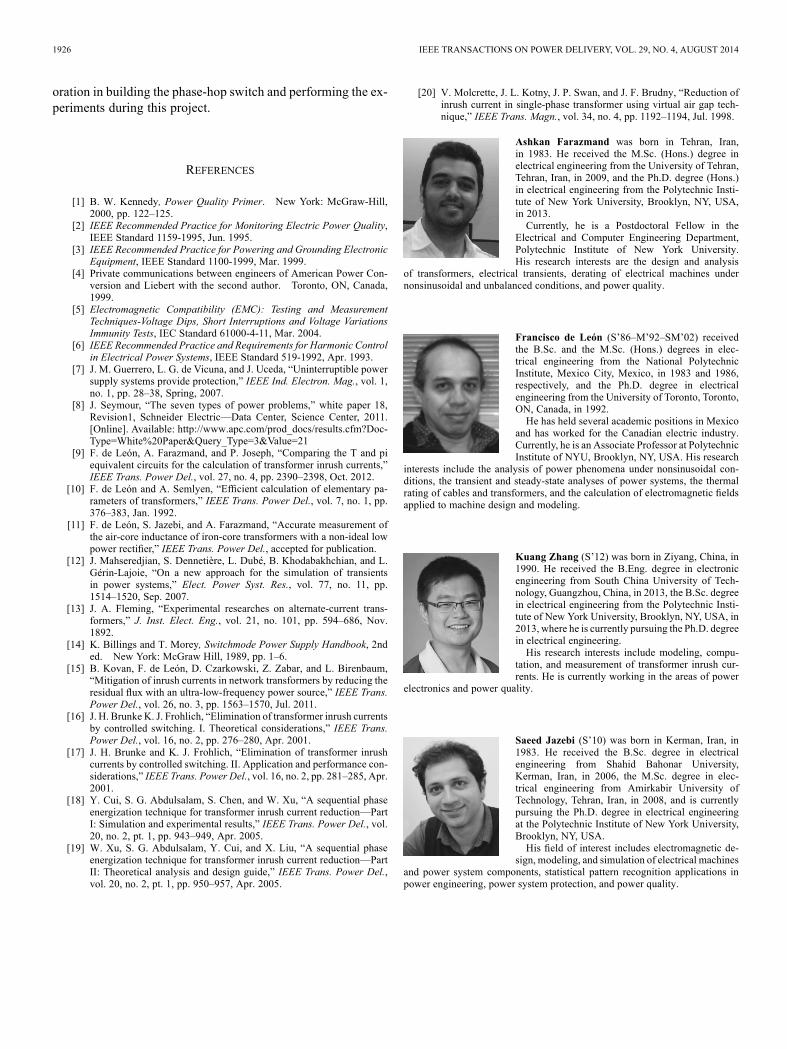
VIII. MAGNETIC-FIELD BEHAVIOR
To shed light into the internal behavior of the transformer,in this section, the magnetic field of the transformer is investi-gated for different operating conditions including: open circuit,normal operation (on-load), zero-crossing inrush, and phase-hop. Simulations are performed using the FEM computer pro-gram, Maxwell 14. Magnetic flux lines are shown inside andoutside the core in Fig. 14. Note that due to the geometrical sym-metry of the transformer, only a part of the core is shown.During open circuit for the situation presented in Fig. 14(a),
the magnetic field is concentrated inside the iron core (the lines
1924 IEEE TRANSACTIONS ON POWER DELIVERY, VOL. 29, NO. 4, AUGUST 2014
Fig. 12. Core flux versus primary current for the first winding of transformer Ta under the worst condition of phase-hop.
Fig. 13. (a) Primary voltage versus time. (b) Primary internal voltage versus time. (c) Core flux versus time. (d) Primary current versus time for the first windingof the transformer under the worst condition of phase-hop.
Fig. 14. Magnetic field behavior for the saturated and nonsaturated transformer iron core: (a) open circuit, (b) normal operating condition—transformer loaded,(c) peak condition for inrush currents at zero-crossing switching, and (d) peak condition for phase-hop currents.
in the window are the boundaries of the windings). Duringnormal operation, when the transformer is supplying the nom-inal load, a part of magnetic flux “leaks” into the interwindingregion [see Fig. 14(b)]. This flux is what produces the leakageinductance. In Fig. 14(c), the magnetic flux for transformer
energization at zero crossing is presented. One can see thatthere is a considerable amount of flux in the air. In fact, theflux distribution resembles the behavior of an air-core inductor.As shown in Fig. 14(d), the flux pattern during the phase-hopdoes not change significantly in comparison with that of the
FARAZMAND et al.: ANALYSIS, MODELING AND SIMULATION OF THE PHASE-HOP CONDITION IN TRANSFORMERS 1925
normal inrush current. However, the amplitude (seen by theconcentration of lines) of the magnetic field is larger.
IX. POSSIBLE SOLUTIONS FOR PHASE-HOP
The transient phenomenon known as transformer inrushcurrents was first published by John Fleming in 1892 [13].Since then, many publications have proposed techniques tolimit inrush currents to prevent its destructive effects. Someof the methods are external (to the transformer) and othersare transformer-based solutions. External solutions consistof preinsertion impedances, negative temperature coefficientthermistors (NTC) [14], transformer core demagnetizing [15],phase-delayed switching [16], [17], and sequential phase en-ergization [18], [19]. Transformer-based solutions consist ofair gaps, virtual gaps [20], using low permeability materialsfor the core, and special designs with larger values of air-coreinductance.To some extent, each of the existing approaches diminishes
inrush currents; however, there is a trade-off with each one ofthem. In addition, some methods are not applicable for phase-hop. External demagnetizing techniques, for example, are notpossible because there is not enough time to demagnetize thetransformer core during the half a cycle between two consec-utive peaks. Switching methods have some problems with themutual effects with switches applied in the UPS systems andalso the reliability of the system. Implementations of preinser-tion impedance methods are very complicated due to the diffi-culty in the detection of the phase-hop condition. Thermistorsdo not work either because at the time of the phase-hop thesystem is already on, therefore, thermistor resistances are verysmall and cannot reduce the inrush current effectively. In gen-eral, there are several problems with the addition of series com-ponents with the transformer: (1) the reliability of the systemreduces, and (2) depending on the voltage level the additionalcomponents need to comply with safety standards, which makesthem expensive.It seems that the best solutions to prevent the destructive ef-
fects of the phase-hop phenomena are transformer based. Appli-cation of these methods will be treated in a forthcoming paper.
X. CONCLUSION
This paper has shown, for the first time, how the occurrenceof the phase-hop phenomenon in transformers can lead to ex-tremely large currents. Phase-hop can occur at any time in apower system because interruptions, voltage sags, and notchingin the network are not predictable. In order to prevent these phe-nomena, a UPS system can be used. However, the action of of-fline UPS systems may itself lead to large levels of inrush cur-rents for the transformers located between the load and the UPSsystem as well.The value of the phase-hop currents can be several times
higher than the magnitude of the “normal” inrush currents thatoccur when a transformer is energized at voltage zero-crossing.The extremely large currents produced by the phase-hop con-
dition can lead to serious problems, such as PQ issues, mechan-ical stresses on transformer windings, and false tripping of vitalprotections. The best techniques to prevent these serious effectsseem to be transformer-based solutions.
Fig. 15. Power and control circuits implemented in the zero-crossing andphase-hop switch.
Fig. 16. Schematics of the phase-hop circuit.
APPENDIX
Fig. 15 presents a block diagram of the power and controlcircuits implemented in the zero-crossing and phase-hop switchdeveloped for this project. This switch consists of voltageregulators, optoisolators, a digital logic control circuit, andmetal–oxide semiconductor field-effect transistor (MOSFET)switches. When the ac power source is on, the optoisolator willpass the sinusoidal waveform to a comparator, which checksfor a zero value. As a result, a 50% duty ratio square wave,which rising and falling edges correspond to the zero-crossingof power source, appears at the output of comparator. The firstrising edge triggers the digital logic control circuit, which turnson the switch and finally energizes the transformer.The phase-hop circuit of the switch is essentially the same
as the zero-crossing circuit except for the digital logic controlcircuit and an extra pair of MOSFETs. Three precise timers areutilized in the control circuit to generate the signals for switches1 and 2 in Fig. 16. Switch 1 consists of two MOSFETs. It closesat the first zero-crossing and only opens between the second andthird zero-crossings. Switch 2 is added to prevent cutting largeinductive currents. When switch 2 is closed, the inrush currentinside the transformer will only flow through switch 2. As aresult, switch 1 and other circuit elements are protected fromthe high voltages caused by large values.
ACKNOWLEDGMENT
The authors would like to thank N. Mahamedau, ex-studentof Polytechnic Institute of New York University, for his collab-
1926 IEEE TRANSACTIONS ON POWER DELIVERY, VOL. 29, NO. 4, AUGUST 2014
oration in building the phase-hop switch and performing the ex-periments during this project.
REFERENCES
[1] B. W. Kennedy, Power Quality Primer. New York: McGraw-Hill,2000, pp. 122–125.
[2] IEEE Recommended Practice for Monitoring Electric Power Quality,IEEE Standard 1159-1995, Jun. 1995.
[3] IEEE Recommended Practice for Powering and Grounding ElectronicEquipment, IEEE Standard 1100-1999, Mar. 1999.
[4] Private communications between engineers of American Power Con-version and Liebert with the second author. Toronto, ON, Canada,1999.
[5] Electromagnetic Compatibility (EMC): Testing and MeasurementTechniques-Voltage Dips, Short Interruptions and Voltage VariationsImmunity Tests, IEC Standard 61000-4-11, Mar. 2004.
[6] IEEE Recommended Practice and Requirements for Harmonic Controlin Electrical Power Systems, IEEE Standard 519-1992, Apr. 1993.
[7] J. M. Guerrero, L. G. de Vicuna, and J. Uceda, “Uninterruptible powersupply systems provide protection,” IEEE Ind. Electron. Mag., vol. 1,no. 1, pp. 28–38, Spring, 2007.
[8] J. Seymour, “The seven types of power problems,” white paper 18,Revision1, Schneider Electric—Data Center, Science Center, 2011.[Online]. Available: http://www.apc.com/prod_docs/results.cfm?Doc-Type=White%20Paper&Query_Type=3&Value=21
[9] F. de León, A. Farazmand, and P. Joseph, “Comparing the T and piequivalent circuits for the calculation of transformer inrush currents,”IEEE Trans. Power Del., vol. 27, no. 4, pp. 2390–2398, Oct. 2012.
[10] F. de León and A. Semlyen, “Efficient calculation of elementary pa-rameters of transformers,” IEEE Trans. Power Del., vol. 7, no. 1, pp.376–383, Jan. 1992.
[11] F. de León, S. Jazebi, and A. Farazmand, “Accurate measurement ofthe air-core inductance of iron-core transformers with a non-ideal lowpower rectifier,” IEEE Trans. Power Del., accepted for publication.
[12] J. Mahseredjian, S. Dennetière, L. Dubé, B. Khodabakhchian, and L.Gérin-Lajoie, “On a new approach for the simulation of transientsin power systems,” Elect. Power Syst. Res., vol. 77, no. 11, pp.1514–1520, Sep. 2007.
[13] J. A. Fleming, “Experimental researches on alternate-current trans-formers,” J. Inst. Elect. Eng., vol. 21, no. 101, pp. 594–686, Nov.1892.
[14] K. Billings and T. Morey, Switchmode Power Supply Handbook, 2nded. New York: McGraw Hill, 1989, pp. 1–6.
[15] B. Kovan, F. de León, D. Czarkowski, Z. Zabar, and L. Birenbaum,“Mitigation of inrush currents in network transformers by reducing theresidual flux with an ultra-low-frequency power source,” IEEE Trans.Power Del., vol. 26, no. 3, pp. 1563–1570, Jul. 2011.
[16] J. H. Brunke K. J. Frohlich, “Elimination of transformer inrush currentsby controlled switching. I. Theoretical considerations,” IEEE Trans.Power Del., vol. 16, no. 2, pp. 276–280, Apr. 2001.
[17] J. H. Brunke and K. J. Frohlich, “Elimination of transformer inrushcurrents by controlled switching. II. Application and performance con-siderations,” IEEE Trans. Power Del., vol. 16, no. 2, pp. 281–285, Apr.2001.
[18] Y. Cui, S. G. Abdulsalam, S. Chen, and W. Xu, “A sequential phaseenergization technique for transformer inrush current reduction—PartI: Simulation and experimental results,” IEEE Trans. Power Del., vol.20, no. 2, pt. 1, pp. 943–949, Apr. 2005.
[19] W. Xu, S. G. Abdulsalam, Y. Cui, and X. Liu, “A sequential phaseenergization technique for transformer inrush current reduction—PartII: Theoretical analysis and design guide,” IEEE Trans. Power Del.,vol. 20, no. 2, pt. 1, pp. 950–957, Apr. 2005.
[20] V. Molcrette, J. L. Kotny, J. P. Swan, and J. F. Brudny, “Reduction ofinrush current in single-phase transformer using virtual air gap tech-nique,” IEEE Trans. Magn., vol. 34, no. 4, pp. 1192–1194, Jul. 1998.
Ashkan Farazmand was born in Tehran, Iran,in 1983. He received the M.Sc. (Hons.) degree inelectrical engineering from the University of Tehran,Tehran, Iran, in 2009, and the Ph.D. degree (Hons.)in electrical engineering from the Polytechnic Insti-tute of New York University, Brooklyn, NY, USA,in 2013.Currently, he is a Postdoctoral Fellow in the
Electrical and Computer Engineering Department,Polytechnic Institute of New York University.His research interests are the design and analysis
of transformers, electrical transients, derating of electrical machines undernonsinusoidal and unbalanced conditions, and power quality.
Francisco de León (S’86–M’92–SM’02) receivedthe B.Sc. and the M.Sc. (Hons.) degrees in elec-trical engineering from the National PolytechnicInstitute, Mexico City, Mexico, in 1983 and 1986,respectively, and the Ph.D. degree in electricalengineering from the University of Toronto, Toronto,ON, Canada, in 1992.He has held several academic positions in Mexico
and has worked for the Canadian electric industry.Currently, he is an Associate Professor at PolytechnicInstitute of NYU, Brooklyn, NY, USA. His research
interests include the analysis of power phenomena under nonsinusoidal con-ditions, the transient and steady-state analyses of power systems, the thermalrating of cables and transformers, and the calculation of electromagnetic fieldsapplied to machine design and modeling.
Kuang Zhang (S’12) was born in Ziyang, China, in1990. He received the B.Eng. degree in electronicengineering from South China University of Tech-nology, Guangzhou, China, in 2013, the B.Sc. degreein electrical engineering from the Polytechnic Insti-tute of New York University, Brooklyn, NY, USA, in2013, where he is currently pursuing the Ph.D. degreein electrical engineering.His research interests include modeling, compu-
tation, and measurement of transformer inrush cur-rents. He is currently working in the areas of power
electronics and power quality.
Saeed Jazebi (S’10) was born in Kerman, Iran, in1983. He received the B.Sc. degree in electricalengineering from Shahid Bahonar University,Kerman, Iran, in 2006, the M.Sc. degree in elec-trical engineering from Amirkabir University ofTechnology, Tehran, Iran, in 2008, and is currentlypursuing the Ph.D. degree in electrical engineeringat the Polytechnic Institute of New York University,Brooklyn, NY, USA.His field of interest includes electromagnetic de-
sign, modeling, and simulation of electrical machinesand power system components, statistical pattern recognition applications inpower engineering, power system protection, and power quality.


![IEEE TRANSACTIONS ON POWER SYSTEMS, VOL. 28, …ecs.syr.edu/faculty/sara/papers/impact.pdf · IEEE TRANSACTIONS ON POWER SYSTEMS, ... connected power system. Authors in [14] ... aggregated](https://img.dokumen.tips/doc/110x75/5ac51ca37f8b9a333d8dacd1/ieee-transactions-on-power-systems-vol-28-ecssyredufacultysarapapers.jpg)