Embed Size (px)
Citation preview

#18-3275 McCallum Road
Abbotsford, BC, V2S 7W8
T. 1.888.855.9733
F. 1.604.855.7378
www.geomediaeng.com
GEOTECHNICAL • ENVIRONMENTAL • MATERIALS
CONSULTING ENGINEERING • INSPECTION & TESTING • MATERIALS TECHNOLOGY
Offices: Abbotsford, Burnaby, Dawson Creek, Fort St. John, Kelowna, Salmon Arm, Squamish
(Sea to Sky), Sechelt (Sunshine Coast), Surrey, Victoria, and Red Deer (AB)
Serving British Columbia’s Construction Industry Since 1987
October 5, 2012 Project No.: G-2265
0932692 BC Ltd c/o
CitiWest Consulting Ltd.
10701 - 133rd
Street
Surrey, BC V3T 3Z3
Attention: Harbhajan Parhar c/o Ron Hung, P.Eng.
Regarding GEOTECHNICAL INVESTIGATION & REPORT
Proposed 33-Unit & 13-Unit Townhouse Projects
19728, 19738, 19754, 19764, and 19770 - 55A Avenue, City of Langley (33 Unit)
19765 & 19773 – 55A Avenue, City of Langley (13 Unit)
1.0. INTRODUCTION
In accordance with your recent authorization, GeoMedia Engineering Ltd. (GME) has completed a
geotechnical investigation, a Benkelman Beam test, and an infiltration test at the above referenced
properties. The purpose of the investigation was to identify subsurface soil conditions including
infiltration rates in order to provide recommendations for site development and foundation design.
This report summarizes the findings and provides geotechnical recommendations for the proposed
development. This report has been prepared in accordance with current geotechnical engineering
principles and practices in British Columbia. This report may be used by the City of Langley for
development and building planning purposes.
2.0. PROPOSED DEVELOPMENT
GME understands that it is planned to rezone the seven (7) single-family residential lots to medium
density residential parcels. The proposed developments are a 33 Unit Townhouse development on the

Geotechnical Investigation and Report October 5, 2012
Proposed 33 Unit & 13 Unit Townhouse Developments Project No.: G-2265
19728, 19738, 19754, 19764, & 19770 - 55A Ave; and 19765 & 19773 – 55A Ave, City of Langley
Copyright 2012 GeoMedia Engineering Ltd. Page 2 of 10
south side of 55A Avenue and a 13 Unit Townhouse development on the north side of 55A Avenue. It is
proposed to construct three (3) level slab-on-grade buildings. Various units will front 55A whereas the
remaining units will front the back lane north of 55A Avenue and south of 55A Avenue. 55A Avenue
will be upgraded to a 12.2m wide road to accommodate street parking. Access to the townhouse units
will be from the proposed lane to the south and the existing lane to the north. Two proposed
development plan concept for the north and south side of 55A Avenue are attached respectively as
Figure 1 and 2.
3.0. SCOPE OF WORK
GME scope of work was to conduct a test pit exploration program, soil infiltration tests, and a
Benkelman Beam test in order to compile this geotechnical report to provide comments and
recommendations for:
• Depth to competent sub-grade for the proposed roads and building foundations,
• Minimum required pavement structure for:
• 55A Avenue, and
• Laneway,
• excavation slopes and fill slopes gradients,
• infiltration rates,
• permissible soil bearing capacity for building foundations, and
• seismic considerations for the development.
Other geotechnical considerations and recommendations pertinent to the development of the site and
building foundations are also provided in this report. It is to be noted that this report does not address
any environmental issues related to the development.
4.0. FIELD WORK
A member of GME’s technical staff visited the site on September 10, 2012 and October 1, 2012 to
complete a site reconnaissance and a subsurface soil investigation for the south and north side
respectively. The site reconnaissance included a review of the site and surrounding properties. The
subsurface soil investigation included excavation of a total of seven (7) test pits with the assistance of a
a subcontracted mid-sized track-mounted excavator. GME’s staff visually logged and classified the soil
excavated from the test pits.
5.0. SITE DESCRIPTION
The site here on will be described as the proposed amalgamated north and south parcel. The sites are
located on the north and south side of 55A Street in the City of Langley, BC. The south property is
rectangular in shape, and has a dimension of about 100m (E-W) by 50m (N-S). The area of the south

Geotechnical Investigation and Report October 5, 2012
Proposed 33 Unit & 13 Unit Townhouse Developments Project No.: G-2265
19728, 19738, 19754, 19764, & 19770 - 55A Ave; and 19765 & 19773 – 55A Ave, City of Langley
Copyright 2012 GeoMedia Engineering Ltd. Page 3 of 10
site is approximately 5000m2. The north property is also rectangular in shape with dimensions of about
40m (E-W) by 50m (N-S). The area of the north parcel is about 2000m2.
The properties are surrounded by single family and multi-family sites.
5.1 Surface Conditions
The overall site is flat. As taken from the City of Langley online maps, the site elevations are about
10m geodetic.
Currently single family residential dwellings preside on the single family lots with the exception of
civic lot of 19764, which was recently demolished and cleared. Accesses to the properties are
served by driveways from 55A Avenue. The laneway to the south is unpaved and has not been
maintained for vehicular access, whereas, the north laneway is paved and moderately used.
Coniferous and deciduous trees are scattered throughout the two sites.
5.2 Subsurface Conditions
The following soil condition describes the specific test pits and is representative of the general soil
condition in the immediate vicinity of each respective test pits. Interpretation of soil conditions
between the test pits is based on an assumed continuity of the subsurface conditions. The soil
conditions described are generalized and are based on the available test pit information. Variation
in stratigraphy can occur between test pit locations, and in the areas not investigated. The soil logs
should only be referenced for soil and groundwater conditions at the specific test pit locations.
5.2.1 Soil Conditions
As previously noted, seven (7) test pits were excavated with the assistance of a midsized track-
mounted excavator. The location and logs of the individual test pits are attached.
Based on the conditions observed in the test pits and the general characterizations of the
geological maps, the stratigraphy in order from the surface consists of:
• loose to compact , organic silt/fill, underlain by
• very stiff clayey silt to the investigative depth.
5.2.2 Groundwater and Infiltration Conditions
Seepage was not encountered in any of the test pits. Based on our judgment and observations,
it appears that groundwater would be perched above the clayey silt later. Two percolation tests
were conducted in the clayey silt layer to evaluate the infiltration rate. The percolation rates

Geotechnical Investigation and Report October 5, 2012
Proposed 33 Unit & 13 Unit Townhouse Developments Project No.: G-2265
19728, 19738, 19754, 19764, & 19770 - 55A Ave; and 19765 & 19773 – 55A Ave, City of Langley
Copyright 2012 GeoMedia Engineering Ltd. Page 4 of 10
conducted onsite indicates that the infiltration rate of the clayey silt is in the order of 1X10-
7cm/s. The infiltration rate of this level indicates that the stratum is considered relatively
impermeable.
6.0. DISCUSSIONS & RECOMMENDATIONS
Based on the site reconnaissance and subsurface investigation, it is considered that the site has
satisfactory soil conditions for the townhouse development to be supported on conventional footings.
Based on the observations and findings, the following recommendations are made for the proposed
development.
6.1 Subdivision Construction
The following recommendations are provided for site preparation and development.
6.1.1 Site Preparation
The native soils underlying the site are sensitive to moisture conditions. During construction
activity, to minimize disturbance of the excavated sub-grade, the following recommendations
should be followed:
� Site preparation should be conducted during extended periods of dry weather;
� Excavated sub-grades should be kept dry. The excavated surface may be need to be sloped
in combination with a series of shallow swales to collect and divert seepage and/or surface
runoff away from excavated areas;
� Any loose or deleterious material should be stripped from all load bearing surfaces from an
offset distance of at least the depth of loose or deleterious material.
� A bedding of at least 100mm of 19mm clear crush gravel, or approved equivalent, should
be placed directly on the excavated surface to protect the excavated sub-grade;
� Any water-softened or disturbed soils should be over-excavated and removed.
� Test pits were excavated during the geotechnical investigation and were backfilled with
loose soil. Where test pits are located within building areas (buildings, sidewalks, roads,
etc), these areas should be re-excavated and backfilled with approved engineered fill and
compacted adequately to the satisfaction of the Geotechnical Engineer.
6.1.2 Cuts and Fills
Final excavation should remove any loose, saturated, and/or disturbed soil prior to construction
of footings, concrete slabs, and/or placement of engineered fill. This includes area of the
building envelope, lanes, sidewalks, decks/pools, and driveways. The stripped areas should

Geotechnical Investigation and Report October 5, 2012
Proposed 33 Unit & 13 Unit Townhouse Developments Project No.: G-2265
19728, 19738, 19754, 19764, & 19770 - 55A Ave; and 19765 & 19773 – 55A Ave, City of Langley
Copyright 2012 GeoMedia Engineering Ltd. Page 5 of 10
extend past the edge of footings, slabs and pavement areas equal to the depth of engineered fill
to be placed below these areas. Stripped sub-grade should be reviewed and approved by GME
prior to placement of engineered fill or footings to confirm the soil bearing capacity.
6.1.3 Trench Excavations
Where excavation is required and exceeds a depth of 1.2m, Work Safe BC guidelines for stable
excavations should be followed to ensure a safe working area. Unsupported temporary
excavated slopes in the native soils may be excavated to ¾(H):1(V) to depths not exceeding
1.2m. For greater depths of excavation and where seepage is encountered, the temporary
perimeter slopes should be flattened and/or shored, to the requirements of the Geotechnical
Engineer.
Dewatering by conventional sump and pump systems for trenches is feasible up to depths of
2.0m below grade, however, it is suggested that recommendations for dewatering be reassessed
once the construction commences to ensure that the depths of excavation and the exposed
ground conditions will not pose a problem with respect to excessive ground water.
The toe of any stockpiled excavated soil should be placed no closer than 1.5m to the edge of the
top of the excavation and be sloped at least 1.5H:1.0V. Machines above the excavation will need
to operate at a horizontal distance from the edge of cut at least twice the depth of excavation,
unless approved by the Geotechnical Engineer.
6.1.4 Structural Fills
All structural and/or site-grading fill should be properly selected and placed/compacted in
accordance with the requirements set-out by the Geotechnical Engineer. This includes the
following requirements, but is not limited to:
• monitoring placement and compaction of all load bearing surfaces and settlement
sensitive areas to:
• fill placement lifts of no more than 300mm thick, and
• at least 95% of the materials,
• Standard Proctor Maximum Dry Density (SPMDD) for buildings, and
• Modified Proctor Maximum Dry Density (MPMDD) for road structures.
• approving proof rolling the excavated sub-grade, and
• reviewing of the excavated sub-grades by the Geotechnical Engineer.
Structural Fill should consist of approved clean granular fill, such as a well-graded 75mm minus
Pit Run Sand and Gravel with less than 8% passing the 0.075mm (#200) sieve and free of any
deleterious material.

Geotechnical Investigation and Report October 5, 2012
Proposed 33 Unit & 13 Unit Townhouse Developments Project No.: G-2265
19728, 19738, 19754, 19764, & 19770 - 55A Ave; and 19765 & 19773 – 55A Ave, City of Langley
Copyright 2012 GeoMedia Engineering Ltd. Page 6 of 10
6.1.4 Roads Pavement Structure
A statistical analysis of the Benkelman Beam rebound readings of 55A exhibited a most probable
spring rebound (MPSR) of 2.83mm. The road also exhibited widespread alligator cracking. Test
pits along the edge of asphalt reveal inadequate sub-base material and thicknesses.
Reconstruction from competent sub-grade is recommended for 55A Avenue. Ditches along the
road and lane will require approved sub-grade fill to bring grades up to sub-base level.
The sub-grade preparation for the 55A and the lane should follow the recommendations
previously noted. The minimum pavement sections conforming to various classifications for the
City of Langley are provided below.
Road Designation Minimum Road Structure
55A Avenue
Limited Local
85mm of Asphalt Concrete
*35mm of Upper Course #2 Mix
*50mm of Lower Course #2 Mix
100mm of 19mm minus Crushed Granular Base
450mm of 100mm minus Pit Run Sand and Gravel
Approved Sub-grade Fill or Approved Sub-grade
Lane 75mm of Asphalt Concrete
100mm of 19mm minus Crushed Granular Base
450mm of 100mm minus Pit Run Sand and Gravel
Approved Sub-grade Fill or Approved Sub-grade
All road structure materials should meet the Master Municipal Construction Documents
(MMCD). The granular base and sub-base materials should be compacted to a minimum of 95%
MPMDD (ASTM D-1557) of the material. The clayey silt sub-grade should be excavated neat and
should not be compacted unless directed otherwise by a geotechnical engineer. The sub-grade is
susceptible to disturbances and being water-softened, hence the sub-grade soils should be
cleaned out just prior to placing engineered fill or the sub-base layer.

Geotechnical Investigation and Report October 5, 2012
Proposed 33 Unit & 13 Unit Townhouse Developments Project No.: G-2265
19728, 19738, 19754, 19764, & 19770 - 55A Ave; and 19765 & 19773 – 55A Ave, City of Langley
Copyright 2012 GeoMedia Engineering Ltd. Page 7 of 10
6.2 Building Design
The following recommendations are provided for building design.
6.2.1 Building Foundations
The buildings are considered to be near ground level, therefore, the foundations of the building
will likely bear on native clayey silt underlying the surficial soils at the site. In accordance with
the building code, the soil conditions can be taken as "Class D". For the design of footings and
with respect to Limit States Design, the following table illustrates the allowable serviceability and
ultimate soil bearing pressures associated with the soil stratum.
Soil Unit SLS
Serviceability Limits States
Soil Bearing Capacity
ULS
Ultimate Limit States
Soil Bearing Capacity
Clayey Silt 100kPa (2.0ksf) 150kPa (3.0ksf)
The bearing capacities listed above must be confirmed by the Geotechnical Engineer upon
excavation.
Strip footings should be no less than 450mm (18”) in width, whereas, the dimensions for pad
footings should be no less than 900mm (36”). For frost protection, footings should be placed at
least 450mm (18”) below the finished grade.
6.2.2 Building Slabs
For slabs-on-grade, a 150mm (6-inch) layer of compacted 19mm clear crushed gravel, or an
approved equivalent, should be placed as bedding. A vapor barrier consisting of minimum
0.15mm (6mil) thick polyethylene sheeting should be placed between the bedding and the
underside of the slab-on-grade.
6.2.3 Perimeter Drains
Perimeter drains are recommended and required under the BC Building Code. Perimeter drains
should be properly designed and installed. Roof drains should not be discharged into the
perimeter drain system and be discharged away from the building. Water collected in the
perimeter and roof drains should be properly collected and discharged to the city storm sewer
system.

Geotechnical Investigation and Report October 5, 2012
Proposed 33 Unit & 13 Unit Townhouse Developments Project No.: G-2265
19728, 19738, 19754, 19764, & 19770 - 55A Ave; and 19765 & 19773 – 55A Ave, City of Langley
Copyright 2012 GeoMedia Engineering Ltd. Page 8 of 10
6.3 Commitments for Field Reviews
GME should be notified in advance during the construction stage in order to facilitate and complete
necessary field reviews. As a minimum, the following field reviews are necessary at the following
stages:
• excavation and trench works, prior to placement of fill,
• placement of fill, prior to construction of footings and slabs, and backfilling, and
• structural load bearing surfaces including buildings and road structures.
Upon request, GME can issue Schedule B for geotechnical aspects of the Building Permit Application
for the individual buildings constructed for this project. To ensure commitment to field reviews,
GME must be notified when the work commences to conduct the necessary field reviews during
construction.
7.0. LIMITATIONS
The recommendations in this report are provided on the assumption that the contractor will be
suitably qualified and experienced. In the event of report revisions, additional funds may be required.
The subsurface conditions may vary between test pits and with time. The interpretation of subsurface
conditions provided is an opinion and not a certification. Stratigraphic variations in ground conditions
are expected due to its historic nature. As such, all explorations involve an inherent risk that some
conditions will not be detected.
Environmental considerations are outside the scope of this geotechnical report. Our
recommendations do not constitute a design of any proposed structural element. Incorporation of
our recommendations into the design does not constitute us as designers. The designers of such
elements must consider the appropriateness of our recommendations.
Samples obtained from site will be retained in our laboratory for 60 days. Should no instructions be
received to the contrary, these samples will then be discarded.
No other warranty, expressed or implied, is made. If the project does not start with 2 years of the
report date, the report may become invalid and further review may be required. This report has been
prepared for the exclusive use of 0932692 c/o CityWest Consulting Ltd, the City of Langley and their
“Approved Users” for specific application to the development mentioned in the report. GME and its
employees accept no responsibility to another party for loss or liability incurred as a result of use of
this report. Any use of this report for purposes other than the intended, should be approved in writing
by GME. Contractors should rely upon their own explorations for costing purposes.
The above referenced report “the Report” may be relied upon by The City as if the Report was directly
issued to The City, subject to the following conditions:

Geotechnical Investigation and Report October 5, 2012
Proposed 33 Unit & 13 Unit Townhouse Developments Project No.: G-2265
19728, 19738, 19754, 19764, & 19770 - 55A Ave; and 19765 & 19773 – 55A Ave, City of Langley
Copyright 2012 GeoMedia Engineering Ltd. Page 9 of 10
• The City will only use the Report for the specific project that is the recipient and subject of
the Report.
• To the extent required by law and subject to the Freedom of Information and Protection of
Privacy Act, R.S.B.C., 1996, c. 165, as amended, The City agrees not to disclose or distribute
the Report furnished hereunder to any third party unless The City on the first page of the
Report places a prominent statement that “THIS REPORT MAY NOT BE RELIED UPON
WITHOUT THE EXPRESS WRITTEN CONSENT OF THE AUTHOR OF THE REPORT”.
• The City’s use of and reliance on the Report is subject to the qualifications and limitations
contained within the Report and The City has no greater rights or conditions of use than as
specified within the Report
• Notwithstanding the above, should a third party recover damages from The City through a
Court of competent jurisdiction, for loss or damage caused to the third party based upon the
third party’s reliance on the Report, and, provided that The City gave reasonable notice of
the third party claim when it was served on The City to GME and consented to GME
becoming a party to the lawsuit in order for it to undertake its own defense, if and when
requested by the GME, GME will indemnify the City if the Court of competent jurisdiction
found that GME committed a negligent act, error, or omission in the preparation of, or
conclusions in, the Report, and that this was the proximate cause of the third party’s loss or
damage.
Electronic media is susceptible to unauthorized modification/alteration, and the Client should not rely
on electronic versions of report/documents. All documents should be obtained directly from GME.
This report is based on the information provided by the client and/or the client’s consultant. GME
relied in good faith upon the information. GME cannot accept responsibility for inaccuracies,
misstatements, omissions or deficiencies in this report resulting from the sources of this information.
This report assumes that GME will be retained to review the soil conditions during construction.


#18-3275 McCallum Road
Abbotsford, BC, V2S 7W8
T. 1.888.855.9733
F. 1.604.855.7378
www.geomediaeng.com
Test Pit Location Plan
Proposed 33-Unit & 13-Unit Townhouse Projects
19728, 19738, 19754, 19764, and 19770 - 55A Avenue, City of Langley (33 Unit)
19765 & 19773 – 55A Avenue, City of Langley (13 Unit)
Percolation Tests were completed in TP2 and TP4

0
2
CLA
SS
IFIC
ATI
ON
W WLWPSA
MP
LE T
YP
E
20 40 60 80
MOISTURE CONTENT& ATTERBERG LIMITS
ST- Shelby Tube PT- Piston Tube VT- Shear Vane Test
MATERIAL DESCRIPTION 100 175 250 325
SO
IL S
YM
BO
L POCKETPENTROMETER
(kPa)
0
5
GS- Grab Sample SPT- Standard Penetration TestSample Type:
SP
T (N
)
ELE
VA
TIO
N
ELEVATION
TP1SOIL LOGPROJECT No G2265CLIENT 0932692 BC Ltd c/o Citiwest Consulting
DATE TESTED September 10, 2012
20 40 60 80
PROJECT Proposed 33 Unit Townhouse Development DATUM
EASTING ---
NORTHING ---
METHOD Tracked Excavator
LOCATION 19728 - 19770 55 A Avenue Langley
TOPSOIL, ORGANICS, SILT, loose, dark brown, moist
DE
PTH
(ft)
SO
IL L
OG
(2 L
OG
S P
ER
PA
GE
) G
2265
LO
GS
.GP
J M
ETR
O T
ES
TIN
G L
AB
.GD
T 9
/20/
12
SPT N VALUE
0.3m: CLAYEY SILT, very stiff, dessicated, rusty brown,moist
DE
PTH
(m)
0.5m: CLAYEY SILT, very stiff, till-like, brown, moist,difficult to dig
No seepage encounteredEnd of hole at 2.4 m.
20 40 60 80
MOISTURE CONTENT& ATTERBERG LIMITS
0
5
SOIL LOG
0
2
DE
PTH
(m)
20 40 60 80
SPT N VALUE DE
PTH
(ft)
ELE
VA
TIO
N
MATERIAL DESCRIPTION 100 175 250 325
POCKETPENTROMETER
(kPa)
SP
T (N
)
SA
MP
LE T
YP
E
SO
IL S
YM
BO
L
CLA
SS
IFIC
ATI
ON
W WLWP
TP2
Thanh
PROJECT No G2265
0.3m: CLAYEY SILT, very stiff, dessicated, rusty brown,moist
Geo Media Engineering ltd.
TOPSOIL, ORGANICS, SILT, loose, dark brown, moist
LOGGED BY:
(Continued Next Page)
CLIENT 0932692 BC Ltd c/o Citiwest Consulting
DATE TESTED September 10, 2012
ELEVATION
PROJECT Proposed 33 Unit Townhouse Development DATUM
EASTING ---
NORTHING ---
METHOD Tracked Excavator
0.5m: CLAYEY SILT, very stiff, till-like, brown, moist,difficult to dig
No seepage encounteredEnd of hole at 1.3 m.
LOCATION 19728 - 19770 55 A Avenue Langley
SO
IL S
YM
BO
L
CLA
SS
IFIC
ATI
ON
W WLWP
ELE
VA
TIO
N
20 40 60 80
POCKETPENTROMETER
(kPa)
SO
IL L
OG
(2 L
OG
S P
ER
PA
GE
) G
2265
LO
GS
.GP
J M
ETR
O T
ES
TIN
G L
AB
.GD
T 9
/20/
12
MATERIAL DESCRIPTION
SA
MP
LE T
YP
E
ST- Shelby Tube PT- Piston Tube VT- Shear Vane TestGS- Grab Sample SPT- Standard Penetration TestSample Type:
SP
T (N
)
100 175 250 325
DATE TESTED September 10, 2012
SPT N VALUE
TP3SOIL LOGPROJECT No G2265CLIENT 0932692 BC Ltd c/o Citiwest Consulting
MOISTURE CONTENT& ATTERBERG LIMITS
ELEVATION
PROJECT Proposed 33 Unit Townhouse Development DATUM
EASTING ---
NORTHING ---
METHOD Tracked Excavator
LOCATION 19728 - 19770 55 A Avenue Langley
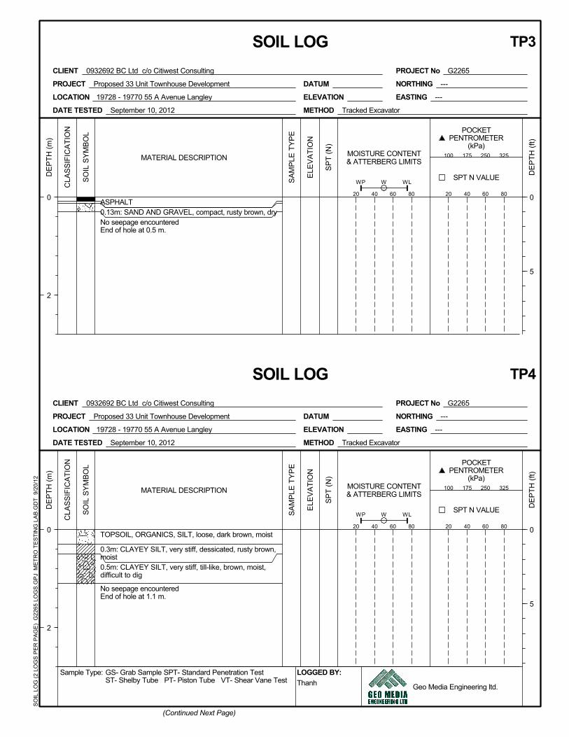
ASPHALT 0
5
DE
PTH
(ft)
20 40 60 80
0.13m: SAND AND GRAVEL, compact, rusty brown, dry
0
2
DE
PTH
(m)
No seepage encounteredEnd of hole at 0.5 m.
20 40 60 80
MOISTURE CONTENT& ATTERBERG LIMITS
0
5
DE
PTH
(ft)
0
2
DE
PTH
(m)
20 40 60 80
SPT N VALUEELE
VA
TIO
N
MATERIAL DESCRIPTION 100 175 250 325
POCKETPENTROMETER
(kPa)
SP
T (N
)
TP4
SA
MP
LE T
YP
E
SO
IL S
YM
BO
L
CLA
SS
IFIC
ATI
ON
W WLWP
Geo Media Engineering ltd.
SOIL LOG
TOPSOIL, ORGANICS, SILT, loose, dark brown, moist
0.5m: CLAYEY SILT, very stiff, till-like, brown, moist,difficult to dig
0.3m: CLAYEY SILT, very stiff, dessicated, rusty brown,moist
ThanhLOGGED BY:
(Continued Next Page)
PROJECT No G2265CLIENT 0932692 BC Ltd c/o Citiwest Consulting
DATE TESTED September 10, 2012
ELEVATION
PROJECT Proposed 33 Unit Townhouse Development DATUM
EASTING ---
NORTHING ---
LOCATION 19728 - 19770 55 A Avenue Langley
No seepage encounteredEnd of hole at 1.1 m.
METHOD Tracked Excavator

PROJECT No G2265
SOIL LOG TP5
SPT N VALUE
20 40 60 80
ELEVATION
0
2
DE
PTH
(ft)
DE
PTH
(m)
ASPHALT 80mm thick0.13m: SAND AND GRAVEL, compact, rusty brown, dry
No seepage encounteredEnd of hole at 0.5 m.
CLIENT 0932692 BC Ltd c/o Citiwest Consulting
DATE TESTED September 10, 2012
LOCATION 19728 - 19770 55 A Avenue Langley
METHOD Tracked Excavator
NORTHING ---
EASTING ---
DATUMPROJECT Proposed 33 Unit Townhouse Development
SO
IL L
OG
(2 L
OG
S P
ER
PA
GE
) G
2265
LO
GS
.GP
J M
ETR
O T
ES
TIN
G L
AB
.GD
T 9
/20/
12
0
5
POCKETPENTROMETER
(kPa)100 175 250 325MATERIAL DESCRIPTION
GS- Grab Sample SPT- Standard Penetration Test LOGGED BY:Thanh
WL
Geo Media Engineering ltd.
MOISTURE CONTENT& ATTERBERG LIMITS
20 40 60 80
ST- Shelby Tube PT- Piston Tube VT- Shear Vane Test
WP
Sample Type:
WCLA
SS
IFIC
ATI
ON
SO
IL S
YM
BO
L
SA
MP
LE T
YP
E
ELE
VA
TIO
N
SP
T (N
)

#18-3275 McCallum Road
Abbotsford, BC, V2S 7W8
T. 1.888.855.9733
F. 1.604.855.7378
www.geomediaeng.com
TEST HOLE LOGS
Date of Investigation: October 1, 2012
Type of Investigation: Hand Dug Test Pits
Test Pit Depth (m) Soil Description
TP6
0.0 - 0.3
0.3 - 0.4
Fill, Sand & Gravel, compact, rusty brown, dry
Clayey Silt/Silt, very stiff, dessicated, rusty
brown, moist
No seepage encountered
End of hole at 0.4m
TP7
0.0 - 0.5
0.5 - 0.6
Fill, Sand & Gravel, compact, rusty brown, dry
Clayey Silt/Silt, very stiff, dessicated, rusty
brown, moist
No seepage encountered
End of hole at 0.6m

Client : 0932692 BC Ltd c/o Citiwest Consulting Ltd Surface : Asphalt Pavement
File : G2265 Surface Temperature : 79 ºF 26.1 ºC
Project : Benkelman Beam Testing Truck Rear Axle Weight : 18000 lb
19728, 19738, 19764, 19770 55A Avenue Date Tested : 5-Sep-12
City of Langley, BC
GeoMedia Engineering Ltd.
Combined
OWP(East) IWP(West) IWP (North) OWP (South)
Number of Tests 13 13 0 13
Average Rebound (mm) 1.41 1.12 - 1.27
Standard Deviation (mm) 0.71 0.46 - 0.61
Most Probable Rebound (mm) 2.82 2.04 - 2.50
Spring Rebound Factor (Aug/Sept 1.15) 1.15 1.15 1.15
Most Probable Spring Rebound Value (mm) 3.24 2.34 - 2.87
Number of Tests 39
Average Rebound (mm) 1.27
Standard Deviation (mm) 0.60
Most Probable Rebound (mm) 2.46
Spring Rebound Factor 1.15
Most Probable Spring Rebound Value (mm) 2.83
Comments
LP Longitudinal (Utility) Patch ACL
OWP Outside Wheel Path TP Transverse (Utility) Patch AXM
IWP Inside Wheel Path PD Poor drainage LC
OJ Open jointed. TC
1.15 1.15
55A Avenue (E-W)
55A Avenue (E-W)
0.60 0.61
2.47 2.50
Westbound Lane (North Side)
26 13
1.26
STATISTICAL SUMMARY
Beam Rebound - Field Data
Alligator cracking, low severity
Alligator cracking, high severity
Longitudinal crack
Transverse crack
2.84 2.87
1.27
Eastbound Lane (South Side)
0.00
0.50
1.00
1.50
2.00
2.50
3.00
0+
00
0+
05
0+
10
0+
15
0+
20
0+
25
0+
30
0+
35
0+
40
0+
45
0+
50
0+
55
0+
60
0+
65
0+
70
0+
75
0+
80
0+
85
0+
90
0+
95
Re
bo
un
d (
mm
)
Station
Beam Rebound - Summary GraphEastbound Lane (South Side) - OWP(East) Eastbound Lane (South Side) - IWP(West)
Westbound Lane (North Side) - OWP (South) Westbound Lane (North Side) - IWP (North)
Station Remarks Remarks
OWP(East) IWP(West) IWP (North) OWP (South)
0+00 AXM (Driveway of 19728) 1.81
0+05 AXM 0.51 1.55
0+10 AXM 1.49
0+15 AXM 1.61 0.59
0+20 AXM 1.39
0+25 AXM 1.95 1.01
0+30 AXM 0.25
0+35 AXM 2.21 1.55
0+40 AXM 1.69
0+45 AXM 2.03 1.59
0+50 AXM 1.35
0+55 AXM 2.71 1.63
0+60 AXM 1.17
0+65 AX 0.53 0.47
0+70 AX 0.77
0+75 AX 1.21 0.91
0+80 AX 1.05
0+85 AX 1.53 0.25
0+90 AX 1.37
0+95 AX 0.33 2.05
1+00 AX 0.57
1+05 AX 1.19 1.51
1+10 AX 0.77
1+15 AX 1.15 2.31
1+20 AX 0.83
1+25 AX (10m west of Stop Sign at 198) 1.27 1.05
Westbound Lane (North Side)Eastbound Lane (South Side)
55A Avenue (E-W)


![eduCAT 1x1 premsa V2s [Nom s de lectura]ateneu.xtec.cat/wikiform/wikiexport/_media/... · Continguts de múltiples fonts Sistema d’accés avui Continguts Plataforma d’accés Entorn](https://img.dokumen.tips/doc/110x75/5e47be99df42815b39174586/educat-1x1-premsa-v2s-nom-s-de-lectura-continguts-de-mltiples-fonts-sistema.jpg)