Embed Size (px)
Citation preview

2
-1
0-8493-1703-7/03/$0.00+$1.50© 2003 by CRC Press LLC
2
Gas-Insulated
Substations
2.1 SF
6
........................................................................................
2
-12.2 Construction and Service Life...........................................
2
-2
Circuit Breaker • Current Transformers • Voltage Transformers • Disconnect Switches • Ground Switches • Bus • Air Connection • Cable Connections • Direct Transformer Connections • Surge Arrester • Control System • Gas Monitor System • Gas Compartments and Zones • Electrical and Physical Arrangement • Grounding • Testing • Installation •Operation and Interlocks • Maintenance
2.3 Economics of GIS.............................................................
2
-17References ....................................................................................
2
-18
A gas-insulated substation (GIS) uses a superior dielectric gas, SF
6
, at moderate pressure for phase-to-phase and phase-to-ground insulation. The high voltage conductors, circuit breaker interrupters,switches, current transformers, and voltage transformers are in SF
6
gas inside grounded metal enclosures.The atmospheric air insulation used in a conventional, air-insulated substation (AIS) requires meters ofair insulation to do what SF
6
can do in centimeters. GIS can therefore be smaller than AIS by up to afactor of 10. A GIS is mostly used where space is expensive or not available. In a GIS the active parts areprotected from the deterioration from exposure to atmospheric air, moisture, contamination, etc. As aresult, GIS is more reliable and requires less maintenance than AIS.
GIS was first developed in various countries between 1968 and 1972. After about 5 years of experience,the use rate increased to about 20% of new substations in countries where space is limited. In othercountries with space easily available, the higher cost of GIS relative to AIS has limited use to special cases.For example, in the U.S., only about 2% of new substations are GIS. International experience with GISis described in a series of CIGRE papers (CIGRE, 1992; 1994; 1982). The IEEE (IEEE Std. C37. 122-1993;IEEE Std C37. 122.1-1993) and the IEC (IEC, 1990) have standards covering all aspects of the design,testing, and use of GIS. For the new user, there is a CIGRE application guide (Katchinski et al., 1998).IEEE has a guide for specifications for GIS (IEEE Std. C37.123-1996).
2.1 SF
6
Sulfur hexaflouride is an inert, nontoxic, colorless, odorless, tasteless, and nonflammable gas consistingof a sulfur atom surrounded by and tightly bonded to six flourine atoms. It is about five times as denseas air. SF
6
is used in GIS at pressures from 400 to 600 kPa absolute. The pressure is chosen so that theSF
6
will not condense into a liquid at the lowest temperatures the equipment experiences. SF
6
has twoto three times the insulating ability of air at the same pressure. SF
6
is about 100 times better than air for
Philip Bolin
Mitsubishi Electric Power
1703_Frame_C02.fm Page 1 Monday, May 12, 2003 6:02 PM
© 2003 by CRC Press LLC

2
-2
Electric Power Substations Engineering
interrupting arcs. It is the universally used interrupting medium for high voltage circuit breakers, replac-ing the older mediums of oil and air. SF
6
decomposes in the high temperature of an electric arc, but thedecomposed gas recombines back into SF
6
so well that it is not necessary to replenish the SF
6
in GIS.There are some reactive decomposition byproducts formed because of the trace presence of moisture,air, and other contaminants. The quantities formed are very small. Molecular sieve absorbants inside theGIS enclosure eliminate these reactive byproducts. SF
6
is supplied in 50-kg gas cylinders in a liquid stateat a pressure of about 6000 kPa for convenient storage and transport. Gas handling systems with filters,compressors, and vacuum pumps are commercially available. Best practices and the personnel safetyaspects of SF
6
gas handling are covered in international standards (IEC, 1995).The SF
6
in the equipment must be dry enough to avoid condensation of moisture as a liquid on thesurfaces of the solid epoxy support insulators because liquid water on the surface can cause a dielectricbreakdown. However, if the moisture condenses as ice, the breakdown voltage is not affected. So dewpoints in the gas in the equipment need to be below about –10°C. For additional margin, levels of lessthan 1000 ppmv of moisture are usually specified and easy to obtain with careful gas handling. Absorbantsinside the GIS enclosure help keep the moisture level in the gas low, even though over time, moisturewill evolve from the internal surfaces and out of the solid dielectric materials (IEEE Std. 1125-1993).
Small conducting particles of mm size significantly reduce the dielectric strength of SF
6
gas. This effectbecomes greater as the pressure is raised past about 600 kPa absolute (Cookson and Farish, 1973). Theparticles are moved by the electric field, possibly to the higher field regions inside the equipment ordeposited along the surface of the solid epoxy support insulators, leading to dielectric breakdown atoperating voltage levels. Cleanliness in assembly is therefore very important for GIS. Fortunately, duringthe factory and field power frequency high voltage tests, contaminating particles can be detected as theymove and cause small electric discharges (partial discharge) and acoustic signals, so they can be removedby opening the equipment. Some GIS equipment is provided with internal “particle traps” that capturethe particles before they move to a location where they might cause breakdown. Most GIS assembliesare of a shape that provides some “natural” low electric field regions where particles can rest withoutcausing problems.
SF
6
is a strong greenhouse gas that could contribute to global warming. At an international treatyconference in Kyoto in 1997, SF
6
was listed as one of the six greenhouse gases whose emissions shouldbe reduced. SF
6
is a very minor contributor to the total amount of greenhouse gases due to humanactivity, but it has a very long life in the atmosphere (half-life is estimated at 3200 years), so the effectof SF
6
released to the atmosphere is effectively cumulative and permanent. The major use of SF
6
is inelectrical power equipment. Fortunately, in GIS the SF
6
is contained and can be recycled. By followingthe present international guidelines for use of SF
6
in electrical equipment (Mauthe et al., 1997), thecontribution of SF
6
to global warming can be kept to less than 0.1% over a 100-year horizon. The emissionrate from use in electrical equipment has been reduced over the last three years. Most of this effect hasbeen due to simply adopting better handling and recycling practices. Standards now require GIS to leakless than 1% per year. The leakage rate is normally much lower. Field checks of GIS in service for manyyears indicate that the leak rate objective can be as low as 0.1% per year when GIS standards are revised.
2.2 Construction and Service Life
GIS is assembled of standard equipment modules (circuit breaker, current transformers, voltage trans-formers, disconnect and ground switches, interconnecting bus, surge arresters, and connections to therest of the electric power system) to match the electrical one-line diagram of the substation. A cross-section view of a 242-kV GIS shows the construction and typical dimensions (Figure 2.1). The modulesare joined using bolted flanges with an “O” ring seal system for the enclosure and a sliding plug-in contactfor the conductor. Internal parts of the GIS are supported by cast epoxy insulators. These supportinsulators provide a gas barrier between parts of the GIS, or are cast with holes in the epoxy to allow gasto pass from one side to the other.
1703_Frame_C02.fm Page 2 Monday, May 12, 2003 6:02 PM
© 2003 by CRC Press LLC

Gas-Insulated Substations
2
-3
Up to about 170 kV system voltage, all three phases are often in one enclosure (Figure 2.2). Above170 kV, the size of the enclosure for “three-phase enclosure,” GIS becomes too large to be practical. Soa “single-phase enclosure” design (Figure 2.1) is used. There are no established performance differencesbetween three-phase enclosure and single-phase enclosure GIS. Some manufacturers use the single-phaseenclosure type for all voltage levels.
Enclosures today are mostly cast or welded aluminum, but steel is also used. Steel enclosures arepainted inside and outside to prevent rusting. Aluminum enclosures do not need to be painted, but maybe painted for ease of cleaning and a better appearance. The pressure vessel requirements for GISenclosures are set by GIS standards (IEEE Std. C37.122-1993; IEC, 1990), with the actual design, man-ufacture, and test following an established pressure vessel standard of the country of manufacture. Becauseof the moderate pressures involved, and the classification of GIS as electrical equipment, third-partyinspection and code stamping of the GIS enclosures are not required.
Conductors today are mostly aluminum. Copper is sometimes used. It is usual to silver plate surfacesthat transfer current. Bolted joints and sliding electrical contacts are used to join conductor sections.There are many designs for the sliding contact element. In general, sliding contacts have many individuallysprung copper contact fingers working in parallel. Usually the contact fingers are silver plated. A contactlubricant is used to ensure that the sliding contact surfaces do not generate particles or wear out overtime. The sliding conductor contacts make assembly of the modules easy and also allow for conductormovement to accommodate the differential thermal expansion of the conductor relative to the enclosure.Sliding contact assemblies are also used in circuit breakers and switches to transfer current from themoving contact to the stationary contacts.
Support insulators are made of a highly filled epoxy resin cast very carefully to prevent formation ofvoids and/or cracks during curing. Each GIS manufacturer’s material formulation and insulator shapehas been developed to optimize the support insulator in terms of electric field distribution, mechanicalstrength, resistance to surface electric discharges, and convenience of manufacture and assembly. Post,
FIGURE 2.1
Single-phase enclosure GIS.
1703_Frame_C02.fm Page 3 Monday, May 12, 2003 6:02 PM
© 2003 by CRC Press LLC

2
-4
Electric Power Substations Engineering
disc, and cone type support insulators are used. Quality assurance programs for support insulators includea high voltage power frequency withstand test with sensitive partial discharge monitoring. Experiencehas shown that the electric field stress inside the cast epoxy insulator should be below a certain level toavoid aging of the solid dielectric material. The electrical stress limit for the cast epoxy support insulatoris not a severe design constraint because the dimensions of the GIS are mainly set by the lightning impulsewithstand level and the need for the conductor to have a fairly large diameter to carry to load currentof several thousand amperes. The result is space between the conductor and enclosure for supportinsulators having low electrical stress.
Service life of GIS using the construction described above has been shown by experience to be morethan 30 years. The condition of GIS examined after many years in service does not indicate any approach-ing limit in service life. Experience also shows no need for periodic internal inspection or maintenance.Inside the enclosure is a dry, inert gas that is itself not subject to aging. There is no exposure of any ofthe internal materials to sunlight. Even the “O” ring seals are found to be in excellent condition becausethere is almost always a “double seal” system — Figure 2.3 shows one approach. The lack of aging hasbeen found for GIS, whether installed indoors or outdoors.
2.2.1 Circuit Breaker
GIS uses essentially the same dead tank SF
6
puffer circuit breakers used in AIS. Instead of SF
6
-to-air asconnections into the substation as a whole, the nozzles on the circuit breaker enclosure are directlyconnected to the adjacent GIS module.
2.2.2 Current Transformers
CTs are inductive ring types installed either inside the GIS enclosure or outside the GIS enclosure(Figure 2.4). The GIS conductor is the single turn primary for the CT. CTs inside the enclosure must be
FIGURE 2.2
Three-phase enclosure GIS.
1703_Frame_C02.fm Page 4 Monday, May 12, 2003 6:02 PM
© 2003 by CRC Press LLC

Gas-Insulated Substations
2
-5
shielded from the electric field produced by the high voltage conductor or high transient voltages canappear on the secondary through capacitive coupling. For CTs outside the enclosure, the enclosure itselfmust be provided with an insulating joint, and enclosure currents shunted around the CT. Both typesof construction are in wide use.
2.2.3 Voltage Transformers
VTs are inductive types with an iron core. The primary winding is supported on an insulating plasticfilm immersed in SF
6
. The VT should have an electric field shield between the primary and secondarywindings to prevent capacitive coupling of transient voltages. The VT is usually a sealed unit with a gasbarrier insulator. The VT is either easily removable so the GIS can be high voltage tested without damagingthe VT, or the VT is provided with a disconnect switch or removable link (Figure 2.5).
FIGURE 2.3
Gas seal for GIS enclosure.
FIGURE 2.4
Current transformers for GIS.
1703_Frame_C02.fm Page 5 Monday, May 12, 2003 6:02 PM
© 2003 by CRC Press LLC

2
-6
Electric Power Substations Engineering
2.2.4 Disconnect Switches
Disconnect switches (Figure 2.6) have a moving contact that opens or closes a gap between stationarycontacts when activated by an insulating operating rod that is itself moved by a sealed shaft coming throughthe enclosure wall. The stationary contacts have shields that provide the appropriate electric field distribution
FIGURE 2.5
Voltage transformers for GIS.
FIGURE 2.6
Disconnect switches for GIS.
1703_Frame_C02.fm Page 6 Monday, May 12, 2003 6:02 PM
© 2003 by CRC Press LLC

Gas-Insulated Substations
2
-7
to avoid too high a surface stress. The moving contact velocity is relatively low (compared to a circuitbreaker moving contact) and the disconnect switch can interrupt only low levels of capacitive current(for example, disconnecting a section of GIS bus) or small inductive currents (for example, transformermagnetizing current). Load break disconnect switches have been furnished in the past, but with improve-ments and cost reductions of circuit breakers, it is not practical to continue to furnish load breakdisconnect switches, and a circuit breaker should be used instead.
2.2.5 Ground Switches
Ground switches (Figure 2.7) have a moving contact that opens or closes a gap between the high voltageconductor and the enclosure. Sliding contacts with appropriate electric field shields are provided at theenclosure and the conductor. A “maintenance” ground switch is operated either manually or by motor
FIGURE 2.7
Ground switches for GIS.
CONNECTING POINT FOR TESTING AND GROUND SHUNT TO ENCLOSURE
GROUNDING SWITCH GROUNDING SWITCH
INSULATING SPACER
CONDUCTOR
ENCLOSURE
CONDUCTOR
INSULATING MOUNTING RING
1703_Frame_C02.fm Page 7 Monday, May 12, 2003 6:02 PM
© 2003 by CRC Press LLC

2
-8
Electric Power Substations Engineering
drive to close or open in several seconds and when fully closed to carry the rated short-circuit currentfor the specified time period (1 or 3 sec) without damage. A “fast-acting” ground switch has a high speeddrive, usually a spring, and contact materials that withstand arcing so it can be closed twice onto anenergized conductor without significant damage to itself or adjacent parts. Fast-acting ground switchesare frequently used at the connection point of the GIS to the rest of the electric power network, not onlyin case the connected line is energized, but also because the fast-acting ground switch is better able tohandle discharge of trapped charge and breaking of capacitive or inductive coupled currents on theconnected line.
Ground switches are almost always provided with an insulating mount or an insulating bushing forthe ground connection. In normal operation the insulating element is bypassed with a bolted shunt tothe GIS enclosure. During installation or maintenance, with the ground switch closed, the shunt can beremoved and the ground switch used as a connection from test equipment to the GIS conductor. Voltageand current testing of the internal parts of the GIS can then be done without removing SF
6
gas or openingthe enclosure. A typical test is measurement of contact resistance using two ground switches (Figure 2.8).
2.2.6 Bus
To connect GIS modules that are not directly connected to each other, an SF
6
bus consisting of an innerconductor and outer enclosure is used. Support
insulators, sliding electrical contacts, and flanged enclo-sure joints are usually the same as for the GIS modules.
2.2.7 Air Connection
SF
6
-to-air bushings (Figure 2.9) are made by attaching a hollow insulating cylinder to a flange on theend of a GIS enclosure. The insulating cylinder contains pressurized SF
6
on the inside and is suitable forexposure to atmospheric air on the outside. The conductor continues up through the center of theinsulating cylinder to a metal end plate. The outside of the end plate has provisions for bolting to an airinsulated conductor. The insulating cylinder has a smooth interior. Sheds on the outside improve the
FIGURE 2.8
Contact resistance measured using ground switch.
1703_Frame_C02.fm Page 8 Monday, May 12, 2003 6:02 PM
© 2003 by CRC Press LLC

Gas-Insulated Substations
2
-9
performance in air under wet and/or contaminated conditions. Electric field distribution is controlledby internal metal shields. Higher voltage SF
6
-to-air bushings also use external shields. The SF
6
gas insidethe bushing is usually the same pressure as the rest of the GIS. The insulating cylinder has most oftenbeen porcelain in the past, but today many are a composite consisting of a fiberglass epoxy inner cylinderwith an external weather shed of silicone rubber. The composite bushing has better contaminationresistance and is inherently safer because it will not fracture as will porcelain.
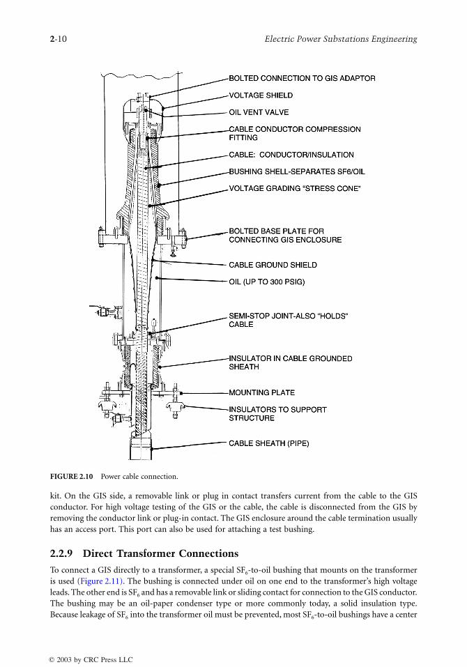
2.2.8 Cable Connections
A cable connecting to a GIS is provided with a cable termination kit that is installed on the cable toprovide a physical barrier between the cable dielectric and the SF
6
gas in the GIS (Figure 2.10). The cabletermination kit also provides a suitable electric field distribution at the end of the cable. Because thecable termination will be in SF
6
gas, the length is short and sheds are not needed. The cable conductoris connected with bolted or compression connectors to the end plate or cylinder of the cable termination
FIGURE 2.9
SF
6
-to-air bushing.
1703_Frame_C02.fm Page 9 Monday, May 12, 2003 6:02 PM
© 2003 by CRC Press LLC
2
-10
Electric Power Substations Engineering
kit. On the GIS side, a removable link or plug in contact transfers current from the cable to the GISconductor. For high voltage testing of the GIS or the cable, the cable is disconnected from the GIS byremoving the conductor link or plug-in contact. The GIS enclosure around the cable termination usuallyhas an access port. This port can also be used for attaching a test bushing.
2.2.9 Direct Transformer Connections
To connect a GIS directly to a transformer, a special SF
6
-to-oil bushing that mounts on the transformeris used (Figure 2.11). The bushing is connected under oil on one end to the transformer’s high voltageleads. The other end is SF
6
and has a removable link or sliding contact for connection to the GIS conductor.The bushing may be an oil-paper condenser type or more commonly today, a solid insulation type.Because leakage of SF
6
into the transformer oil must be prevented, most SF
6
-to-oil bushings have a center
FIGURE 2.10
Power cable connection.
1703_Frame_C02.fm Page 10 Monday, May 12, 2003 6:02 PM
© 2003 by CRC Press LLC

Gas-Insulated Substations
2
-11
section that allows any SF
6
leakage to go to the atmosphere rather than into the transformer. For testing,the SF
6
end of the bushing is disconnected from the GIS conductor after gaining access through anopening in the GIS enclosure. The GIS enclosure of the transformer can also be used for attaching a testbushing.
2.2.10 Surge Arrester
Zinc oxide surge arrester elements suitable for immersion in SF
6
are supported by an insulating cylinderinside a GIS enclosure section to make a surge arrester for overvoltage control (Figure 2.12). Because theGIS conductors are inside in a grounded metal enclosure, the only way for lightning impulse voltages toenter is through the connections of the GIS to the rest of the electrical system. Cable and direct transformerconnections are not subject to lightning strikes, so only at SF
6
-to-air bushing connections is lightning aconcern. Air-insulated surge arresters in parallel with the SF
6
-to-air bushings usually provide adequateprotection of the GIS from lightning impulse voltages at a much lower cost than SF
6
insulated arresters.Switching surges are seldom a concern in GIS because with SF
6
insulation the withstand voltages forswitching surges are not much less than the lightning impulse voltage withstand. In AIS there is asignificant decrease in withstand voltage for switching surges than for lightning impulse because thelonger time span of the switching surge allows time for the discharge to completely bridge the longinsulation distances in air. In the GIS, the short insulation distances can be bridged in the short timespan of a lightning impulse so the longer time span of a switching surge does not significantly decreasethe breakdown voltage. Insulation coordination studies usually show there is no need for surge arresters
FIGURE 2.11
Direct SF
6
bus connection to transformer.
1703_Frame_C02.fm Page 11 Monday, May 12, 2003 6:02 PM
© 2003 by CRC Press LLC

2
-12
Electric Power Substations Engineering
in a GIS; however, many users specify surge arresters at transformers and cable connections as the mostconservative approach.
2.2.11 Control System
For ease of operation and convenience in wiring the GIS back to the substation control room, a localcontrol cabinet (LCC) is provided for each circuit breaker position (Figure 2.13). The control and powerwires for all the operating mechanisms, auxiliary switches, alarms, heaters, CTs, and VTs are broughtfrom the GIS equipment modules to the LCC using shielded multiconductor control cables. In additionto providing terminals for all the GIS wiring, the LCC has a mimic diagram of the part of the GIS beingcontrolled. Associated with the mimic diagram are control switches and position indicators for the circuitbreaker and switches. Annunciation of alarms is also usually provided in the LCC. Electrical interlockingand some other control functions can be conveniently implemented in the LCC. Although the LCC isan extra expense, with no equivalent in the typical AIS, it is so well established and popular that attemptsto eliminate it to reduce cost have not succeeded. The LCC does have the advantage of providing a veryclear division of responsibility between the GIS manufacturer and user in terms of scope of equipmentsupply.
Switching and circuit breaker operation in a GIS produces internal surge voltages with a very fast risetime on the order of nanoseconds and a peak voltage level of about 2 per unit. These “very fast transientovervoltages” are not a problem inside the GIS because the duration of this type of surge voltage is veryshort — much shorter than the lightning impulse voltage. However, a portion of the VFTO will emergefrom the inside of the GIS at any place where there is a discontinuity of the metal enclosure — forexample, at insulating enclosure joints for external CTs or at the SF
6
-to-air bushings. The resulting“transient ground rise voltage” on the outside of the enclosure may cause some small sparks across theinsulating enclosure joint or to adjacent grounded parts. These may alarm nearby personnel but are notharmful to a person because the energy content is very low. However, if these VFT voltages enter thecontrol wires, they could cause faulty operation of control devices. Solid-state controls can be particularlyaffected. The solution is thorough shielding and grounding of the control wires. For this reason, in aGIS, the control cable shield should be grounded at both the equipment and the LCC ends using eithercoaxial ground bushings or short connections to the cabinet walls at the location where the control cablefirst enters the cabinet.
FIGURE 2.12
Surge arrester for GIS.
1703_Frame_C02.fm Page 12 Monday, May 12, 2003 6:02 PM
© 2003 by CRC Press LLC

Gas-Insulated Substations
2
-13
2.2.12 Gas Monitor System
The insulating and interrupting capability of the SF
6
gas depends on the density of the SF
6
gas being ata minimum level established by design tests. The pressure of the SF
6
gas varies with temperature, so amechanical temperature-compensated pressure switch is used to monitor the equivalent of gas density(Figure 2.14). GIS is filled with SF
6
to a density far enough above the minimum density for full dielectricand interrupting capability so that from 10 to 20% of the SF
6
gas can be lost before the performance ofthe GIS deteriorates. The density alarms provide a warning of gas being lost, and can be used to operatethe circuit breakers and switches to put a GIS that is losing gas into a condition selected by the user.Because it is much easier to measure pressure than density, the gas monitor system usually has a pressuregage. A chart is provided to convert pressure and temperature measurements into density. Microproces-sor-based measurement systems are available that provide pressure, temperature, density, and evenpercentage of proper SF
6
content. These can also calculate the rate at which SF
6
is being lost. However,they are significantly more expensive than the mechanical temperature-compensated pressure switches,so they are supplied only when requested by the user.
2.2.13 Gas Compartments and Zones
A GIS is divided by gas barrier insulators into gas compartments for gas handling purposes. In somecases, the use of a higher gas pressure in the circuit breaker than is needed for the other devices, requires
FIGURE 2.13
Local control cabinet for GIS.
1703_Frame_C02.fm Page 13 Monday, May 12, 2003 6:02 PM
© 2003 by CRC Press LLC

2
-14
Electric Power Substations Engineering
that the circuit breaker be a separate gas compartment. Gas handling systems are available to easily processand store about 1000 kg of SF
6
at one time, but the length of time needed to do this is longer than mostGIS users will accept. GIS is therefore divided into relatively small gas compartments of less than severalhundred kg. These small compartments may be connected with external bypass piping to create a largergas zone for density monitoring. The electrical functions of the GIS are all on a three-phase basis, sothere is no electrical reason not to connect the parallel phases of a single-phase enclosure type of GISinto one gas zone for monitoring. Reasons for not connecting together many gas compartments intolarge gas zones include a concern with a fault in one gas compartment causing contamination in adjacentcompartments and the greater amount of SF
6
lost before a gas loss alarm. It is also easier to locate a leakif the alarms correspond to small gas zones, but a larger gas zone will, for the same size leak, give moretime to add SF
6
between the first alarm and second alarm. Each GIS manufacturer has a standard approachto gas compartments and gas zones, but will, of course, modify the approach to satisfy the concerns ofindividual GIS users.
2.2.14 Electrical and Physical Arrangement
For any electrical one-line diagram there are usually several possible physical arrangements. The shapeof the site for the GIS and the nature of connecting lines and/or cables should be considered. Figure 2.15compares a “natural” physical arrangement for a breaker and a half GIS with a “linear” arrangement.
Most GIS designs were developed initially for a double bus, single breaker arrangement (Figure 2.2).This widely used approach provides good reliability, simple operation, easy protective relaying, excellenteconomy, and a small footprint. By integrating several functions into each GIS module, the cost of thedouble bus, single breaker arrangement can be significantly reduced. An example is shown in Figure 2.16.Disconnect and ground switches are combined into a “three-position switch” and made a part of eachbus module connecting adjacent circuit breaker positions. The cable connection module includes thecable termination, disconnect switches, ground switches, a VT, and surge arresters.
2.2.15 Grounding
The individual metal enclosure sections of the GIS modules are made electrically continuous either bythe flanged enclosure joint being a good electrical contact in itself or with external shunts bolted to theflanges or to grounding pads on the enclosure. While some early single-phase enclosure GIS were “single
FIGURE 2.14
SF
6
density monitor for GIS.
1703_Frame_C02.fm Page 14 Monday, May 12, 2003 6:02 PM
© 2003 by CRC Press LLC

Gas-Insulated Substations
2
-15
point grounded” to prevent circulating currents from flowing in the enclosures, today the universalpractice is to use “multipoint grounding” even though this leads to some electrical losses in the enclosuresdue to circulating currents. The three enclosures of a single-phase GIS should be bonded to each otherat the ends of the GIS to encourage circulating currents to flow. These circulating enclosure currents actto cancel the magnetic field that would otherwise exist outside the enclosure due to the conductor current.Three-phase enclosure GIS does not have circulating currents, but does have eddy currents in theenclosure, and should also be multipoint grounded. With multipoint grounding and the resulting manyparallel paths for the current from an internal fault to flow to the substation ground grid, it is easy tokeep the touch and step voltages for a GIS to the safe levels prescribed in IEEE 80.
2.2.16 Testing
Test requirements for circuit breakers, CTs, VTs, and surge arresters are not specific for GIS and will notbe covered in detail here. Representative GIS assemblies having all of the parts of the GIS except for thecircuit breaker are design tested to show that the GIS can withstand the rated lightning impulse voltage,
FIGURE 2.15
One-and-one-half circuit breaker layouts.
1703_Frame_C02.fm Page 15 Monday, May 12, 2003 6:02 PM
© 2003 by CRC Press LLC

2-16 Electric Power Substations Engineering
switching impulse voltage, power frequency overvoltage, continuous current, and short-circuit current.Standards specify the test levels and how the tests must be done. Production tests of the factory-assembledGIS (including the circuit breaker) cover power frequency withstand voltage, conductor circuit resistance,leak checks, operational checks, and CT polarity checks. Components such as support insulators, VTs,and CTs are tested in accordance with the specific requirements for these items before assembly into theGIS. Field tests repeat the factory tests. The power frequency withstand voltage test is most importantas a check of the cleanliness of the inside of the GIS in regard to contaminating conducting particles, asexplained in the SF6 section above. Checking of interlocks is also very important. Other field tests maybe done if the GIS is a very critical part of the electric power system, when, for example, a surge voltagetest may be requested.
2.2.17 Installation
The GIS is usually installed on a monolithic concrete pad or the floor of a building. It is most oftenrigidly attached by bolting and/or welding the GIS support frames to embedded steel plates or beams.Chemical drill anchors can also be used. Expansion drill anchors are not recommended because dynamicloads may loosen expansion anchors when the circuit breaker operates. Large GIS installations may needbus expansion joints between various sections of the GIS to adjust to the fit-up in the field and, in somecases, provide for thermal expansion of the GIS. The GIS modules are shipped in the largest practicalassemblies. At the lower voltage level, two or more circuit breaker positions can be delivered fully
FIGURE 2.16 Integrated (combined function) GIS.
1703_Frame_C02.fm Page 16 Monday, May 12, 2003 6:02 PM
© 2003 by CRC Press LLC

Gas-Insulated Substations 2-17
assembled. The physical assembly of the GIS modules to each other using the bolted flanged enclosurejoints and sliding conductor contacts goes very quickly. More time is used for evacuation of air from gascompartments that have been opened, filling with SF6 gas, and control system wiring. The field tests arethen done. For a high voltage GIS shipped as many separate modules, installation and testing takes abouttwo weeks per circuit breaker position. Lower voltage systems shipped as complete bays, and mostlyfactory-wired, can be installed more quickly.
2.2.18 Operation and Interlocks
Operation of a GIS in terms of providing monitoring, control, and protection of the power system as awhole is the same as for an AIS except that internal faults are not self-clearing so reclosing should notbe used for faults internal to the GIS. Special care should be taken for disconnect and ground switchoperation because if these are opened with load current flowing, or closed into load or fault current, thearcing between the switch moving and stationary contacts will usually cause a phase-to-phase fault inthree-phase enclosure GIS or to a phase-to-ground fault in single-phase enclosure GIS. The internal faultwill cause severe damage inside the GIS. A GIS switch cannot be as easily or quickly replaced as an AISswitch. There will also be a pressure rise in the GIS gas compartment as the arc heats the gas. In extremecases, the internal arc will cause a rupture disk to operate or may even cause a burn-through of theenclosure. The resulting release of hot, decomposed SF6 gas may cause serious injury to nearby personnel.For both the sake of the GIS and the safety of personnel, secure interlocks are provided so that the circuitbreaker must be open before an associated disconnect switch can be opened or closed, and the disconnectswitch must be open before the associated ground switch can be closed or opened.
2.2.19 Maintenance
Experience has shown that the internal parts of GIS are so well protected inside the metal enclosure thatthey do not age and as a result of proper material selection and lubricants, there is negligible wear of theswitch contacts. Only the circuit breaker arcing contacts and the teflon nozzle of the interrupter experiencewear proportional to the number of operations and the level of the load or fault currents being inter-rupted. Good contact and nozzle materials combined with the short interrupting time of modern circuitbreakers provide, typically, for thousands of load current interruption operations and tens of full-ratedfault current interruptions before there is any need for inspection or replacement. Except for circuitbreakers in special use such as at a pumped storage plant, most circuit breakers will not be operatedenough to ever require internal inspection. So most GIS will not need to be opened for maintenance.The external operating mechanisms and gas monitor systems should be visually inspected, with thefrequency of inspection determined by experience.
2.3 Economics of GIS
The equipment cost of GIS is naturally higher than that of AIS due to the grounded metal enclosure, theprovision of an LCC, and the high degree of factory assembly. A GIS is less expensive to install than anAIS. The site development costs for a GIS will be much lower than for an AIS because of the muchsmaller area required for the GIS. The site development advantage of GIS increases as the system voltageincreases because high voltage AIS take very large areas because of the long insulating distances inatmospheric air. Cost comparisons in the early days of GIS projected that, on a total installed cost basis,GIS costs would equal AIS costs at 345 kV. For higher voltages, GIS was expected to cost less than AIS.However, the cost of AIS has been reduced significantly by technical and manufacturing advances (espe-cially for circuit breakers) over the last 30 years, but GIS equipment has not shown any cost reductionuntil very recently. Therefore, although GIS has been a well-established technology for a long time, witha proven high reliability and almost no need for maintenance, it is presently perceived as costing toomuch and is only applicable in special cases where space is the most important factor.
1703_Frame_C02.fm Page 17 Monday, May 12, 2003 6:02 PM
© 2003 by CRC Press LLC

2-18 Electric Power Substations Engineering
Currently, GIS costs are being reduced by integrating functions as described in the arrangement sectionabove. As digital control systems become common in substations, the costly electromagnetic CTs andVTs of a GIS will be replaced by less-expensive sensors such as optical VTs and Rogowski coil CTs. Theseless-expensive sensors are also much smaller, reducing the size of the GIS and allowing more bays of GISto be shipped fully assembled. Installation and site development costs are correspondingly lower. TheGIS space advantage over AIS increases. GIS can now be considered for any new substation or theexpansion of an existing substation without enlarging the area for the substation.
References
Cookson, A. H. and Farish, O., Particle-initiated breakdown between coaxial electrodes in compressedSF6, IEEE Transactions on Power Apparatus and Systems, Vol. PAS-92(3), 871-876, May/June, 1973.
IEC 1634: 1995, IEC technical report: High-voltage switchgear and controlgear — use and handling ofsulphur hexafluoride (SF6) in high-voltage switchgear and controlgear.
IEEE Guide for Moisture Measurement and Control in SF6 Gas-Insulated Equipment, IEEE Std. 1125-1993. IEEE Guide for Gas-Insulated Substations, IEEE Std. C37.122.1-1993.IEEE Standard for Gas-Insulated Substations, IEEE Std. C37.122-1993.IEEE Guide to Specifications for Gas-Insulated, Electric Power Substation Equipment, IEEE Std. C37.123-1996.IEC 517: 1990, Gas-insulated metal-enclosed switchgear for rated voltages of 72.5 kV and above (3rd ed.).Jones, D. J., Kopejtkova, D., Kobayashi, S., Molony, T., O’Connell, P., and Welch, I. M., GIS in service —
experience and recommendations, Paper 23-104 of CIGRE General Meeting, Paris, 1994.Katchinski, U., Boeck, W., Bolin, P. C., DeHeus, A., Hiesinger, H., Holt, P.-A., Murayama, Y., Jones, J.,
Knudsen, O., Kobayashi, S., Kopejtkova, D., Mazzoleni, B., Pryor, B., Sahni, A. S., Taillebois, J.-P.,Tschannen, C., and Wester, P., User guide for the application of gas-insulated switchgear (GIS) forrated voltages of 72.5 kV and above, CIGRE Report 125, Paris, April 1998.
Kawamura, T., Ishi, T., Satoh, K., Hashimoto, Y., Tokoro, K., and Harumoto, Y., Operating experience ofgas-insulated switchgear (GIS) and its influence on the future substation design, Paper 23-04 ofCIGRE General Meeting, Paris, 1982.
Kopejtkova, D., Malony, T., Kobayashi, S., and Welch, I. M., A twenty-five year review of experience withSF6 gas-insulated substations (GIS), Paper 23-101 of CIGRE General Meeting, Paris, 1992.
Mauthe, G., Pryor, B. M., Neimeyer, L., Probst, R., Poblotzki, J., Bolin, P., O’Connell, P., and Henriot, J.,SF6 recycling guide: Re-use of SF6 gas in electrical power equipment and final disposal, CIGREReport 117, Paris, August, 1997.
1703_Frame_C02.fm Page 18 Monday, May 12, 2003 6:02 PM
© 2003 by CRC Press LLC


