Embed Size (px)
DESCRIPTION
Gramme's heavy oils
Citation preview

Tekna Heavy Oil Technology for
Offshore Applications
Chemistry and Physics of Heavy Oil and other
Dispersions
Per Eivind Gramme
Special Advisor
Grenland Group ASAStavanger, 14.-15. May 2009
Factors stabilizing emulsion and slows down gas/oil/water separation
Inorganic particles
Organic precipitated particles
Napthenic acids
Asphaltenes
ResinsWax
Organic acidsEtc.
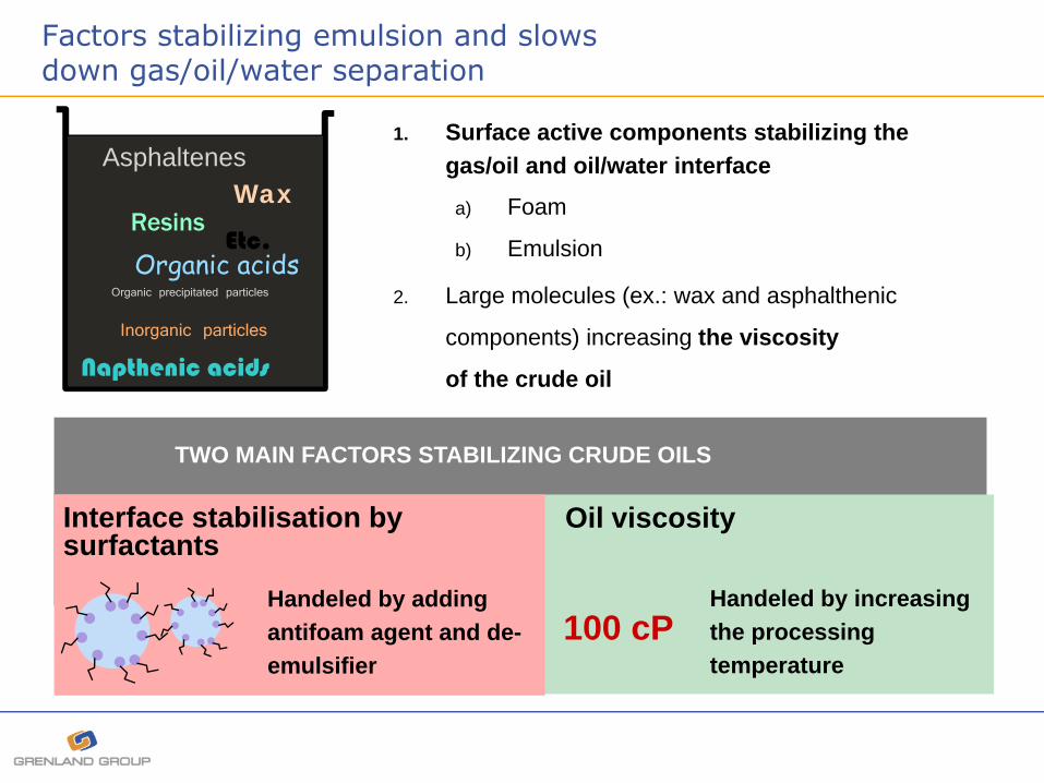
1. Surface active components stabilizing the gas/oil and oil/water interface
a) Foam
b) Emulsion
2. Large molecules (ex.: wax and asphalthenic
components) increasing the viscosity
of the crude oil
TWO MAIN FACTORS STABILIZING CRUDE OILS
Interface stabilisation by surfactants
Handeled by adding antifoam agent and de-emulsifier
Oil viscosity
Handeled by increasing the processing temperature
100 cP

Factors stabilizing emulsion
Viscosity of crude oil
Surfactants
Particles that are surface active

The emulsion stability is a function of Water Cut

The emulsion stability is a function of Water Cut
Water cut
▪ Water cut

The effect of water cut and the need for de-emulsifier

The crude oil separation properties are dependant on the system pressure!
1 10 100 1000System pressure (bar)
0
20
40
60
80
100Relative rate of separation
Bottom hole sample
Wellhead sample
Separator 1
Separator 2
Stock tank oil
Downhole Separation
Subsea Separation
Topside Separation
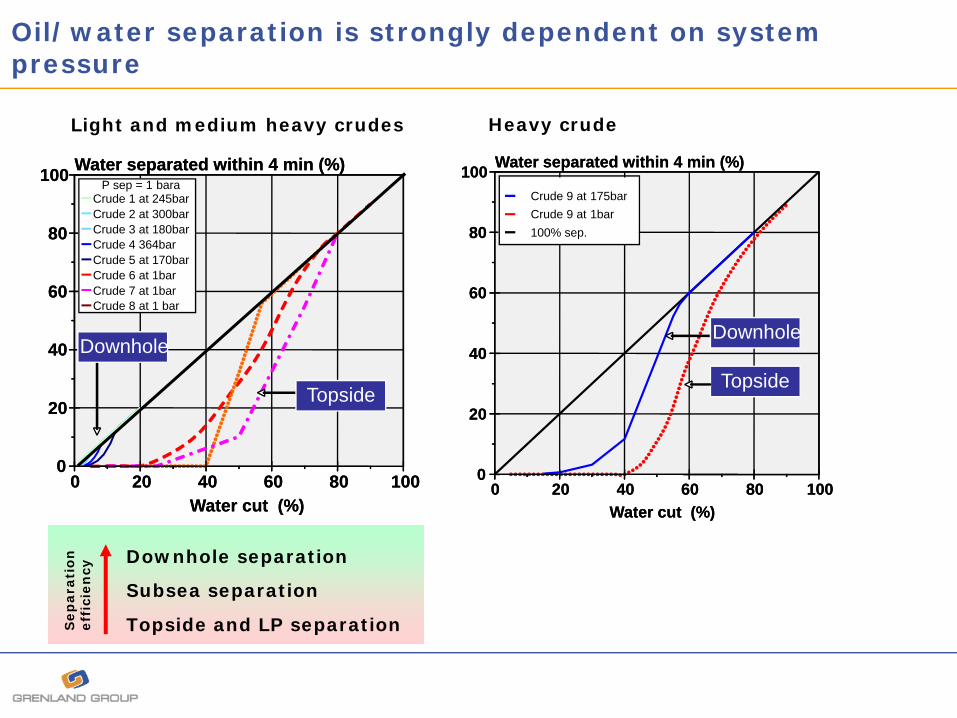
Oil/water separation is strongly dependent on system pressure
0 20 40 60 80 100Water cut (%)
0
20
40
60
80
100 Water separated within 4 min (%)P sep = 1 bara
Crude 1 at 245barCrude 2 at 300barCrude 3 at 180barCrude 4 364barCrude 5 at 170barCrude 6 at 1barCrude 7 at 1barCrude 8 at 1 bar
Downhole
Topside
0 20 40 60 80 100Water cut (%)
0
20
40
60
80
100 Water separated within 4 min (%)P sep = 1 bara
Crude 1 at 245barCrude 2 at 300barCrude 3 at 180barCrude 4 364barCrude 5 at 170barCrude 6 at 1barCrude 7 at 1barCrude 8 at 1 bar
Downhole
Topside
0 20 40 60 80 100Water cut (%)
0
20
40
60
80
100 Water separated within 4 min (%)
Crude 9 at 175barCrude 9 at 1bar100% sep.
Downhole
Topside
0 20 40 60 80 100Water cut (%)
0
20
40
60
80
100 Water separated within 4 min (%)
Crude 9 at 175barCrude 9 at 1bar100% sep.
Downhole
Topside
Light and medium heavy crudes Heavy crude
Sep
ara
tio
n
eff
icie
ncy
Topside and LP separation
Subsea separation
Downhole separation

The structure of oil/water interface and fluid viscosity changes with T and P
T1 and P1 T2 and P2

The important stages of destabilization
Step 1: Drainage of liquid between droplets
Step 2: Breaking the droplet surface
Surfactants
Polymerization at the interface
Action 1: Control viscosity by temperature or use diluent
Action 2: Remove surfactants from the interface using de-emulsifier or (Psys)

Step 1
Design the prosess such that the oil viscosity in the gravity separators and the electrostatic coalescer is less than 5 – 7 cP!

0
5
10
15
20
10 60 110 160 210
Temperature (deg.C)
Oil
visc
osity
(cP)
Oil continuous separation of heavy crudes is dependent on the viscosity which is controlled by the the processing temperature
0
50
100
150
200
10 15 20 25 30
API Density (-)
Tem
pera
ture
(Deg
.C)
The heavy crudes need to be heated in order to bring the viscosity below approx. 5 to 7 cP for efficient processing
Operation at higher temperatures is limited by materials and corrosion aspects, instrumentation and safety aspects!
Data from fields offshore Brasil
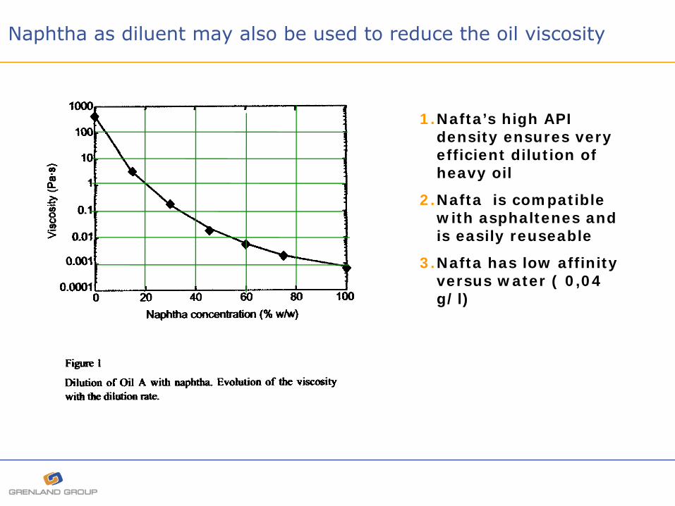
Naphtha as diluent may also be used to reduce the oil viscosity
1.Nafta’s high API density ensures very efficient dilution of heavy oil
2.Nafta is compatible with asphaltenes and is easily reuseable
3.Nafta has low affinity versus water ( 0,04 g/l)

Effects of viscosity and surfactants on separation
0
20
40
60
80
100
120
140
2 7 12 17 22 27 32 37
Viscosity continuous phase
Req
uire
d liq
uid
resi
denc
e tim
e
Separation limited by viscocity
Separation limited by surfactant stabilization
Oil from field A
Destabilization using de-emulsifiers
Viscosity reduction by increasing the prosessing temperature
For efficient gravity separation the viscosity of the oil should be less than 10 cP preferably below 7 cP
10 cP
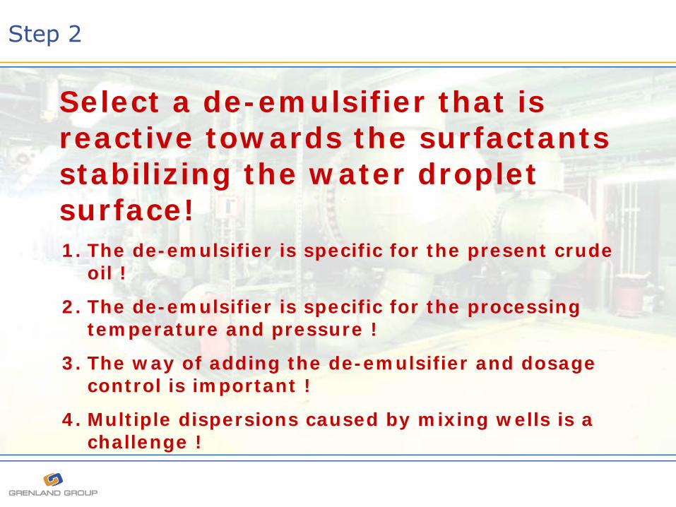
Step 2
Select a de-emulsifier that is reactive towards the surfactants stabilizing the water droplet surface!1. The de-emulsifier is specific for the present crude
oil !
2. The de-emulsifier is specific for the processing temperature and pressure !
3. The way of adding the de-emulsifier and dosage control is important !
4. Multiple dispersions caused by mixing wells is a challenge !
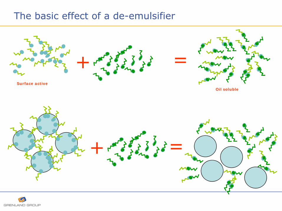
The basic effect of a de-emulsifier
+ =Surface active
Oil soluble
+ =
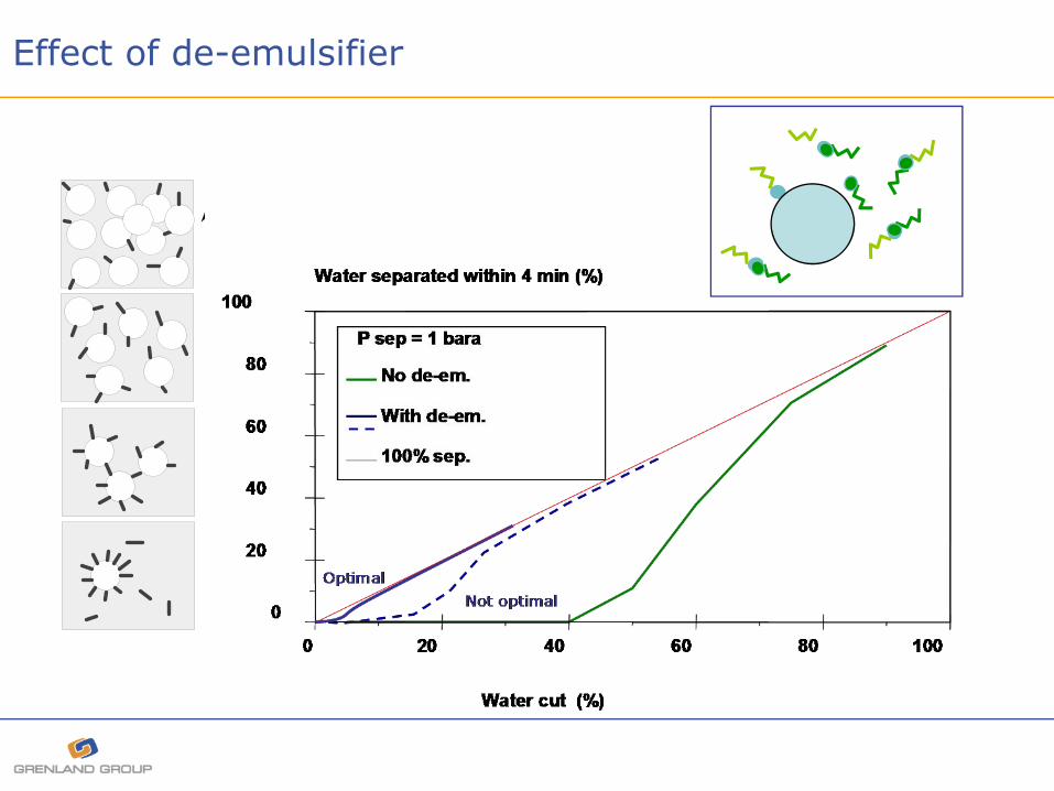
Effect of de-emulsifier
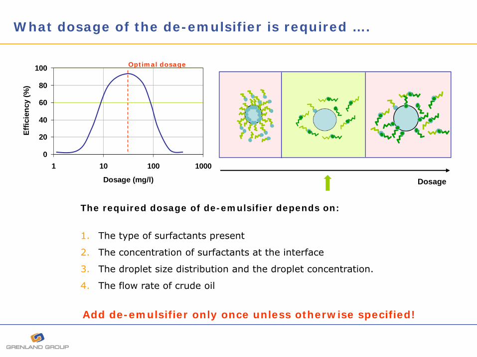
What dosage of the de-emulsifier is required ….
0
20
40
60
80
100
1 10 100 1000
Dosage (mg/l)
Effic
ienc
y (%
)
Optimal dosage
The required dosage of de-emulsifier depends on:
1. The type of surfactants present
2. The concentration of surfactants at the interface
3. The droplet size distribution and the droplet concentration.
4. The flow rate of crude oil
Add de-emulsifier only once unless otherwise specified!
Dosage

The dosage of de-emulsifiers ….
0 20 40 60 80 100
Demulsifier dosage (ppm)
0
20
40
60
80
100% of water separated in 2 min.
Up Do
1. De-emulsifiers should always be added just upstream choke valves or a high shear devicein order to obtain fast mixing into the crude and to improve the access to the surface of the droplets.
2. The more viscous the crude is the longer reaction time is needed. If possible, deemulsifiers should be added at well head or ever better, down-hole.
3. The dosage of de-emulsifier is dependent on the system pressure.
Usually less de-emulsifier is required at higher system pressure
4. De-emulsifier should be eveluated at system conditions and NOT using stabilized crudes and bottle tests.
Effect of adding deemulsifier upstream a choke valve (19 API crude)
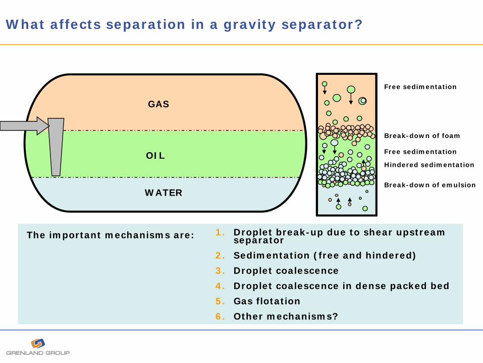
What affects separation in a gravity separator?
GAS
OIL
WATER
Free sedimentation
Break-down of foam
Free sedimentation
Hindered sedimentation
Break-down of emulsion
The important mechanisms are: 1. Droplet break-up due to shear upstream separator
2. Sedimentation (free and hindered)
3. Droplet coalescence
4. Droplet coalescence in dense packed bed
5. Gas flotation
6. Other mechanisms?

Viscosity correction factors for break-up models
( ) ⎥⎦
⎤⎢⎣
⎡
∗σ∗ρμ
∗+= 5.0smd
dµdisp D
964.002.1F
Correction factor for dispersed phase viscosity based on the Viscosity no.:
Correction factor for the continous phase (tentative):
4.0
0c
cµcontF ⎟⎟
⎠
⎞⎜⎜⎝
⎛μμ
= where µc0 = 1 cP

Effect of viscosity on droplet break-up
Continuous phase viscosity Dispersed phase viscosity

Effect of oil viscosity on coalescence and sedimentation in gravity separation
Droplet coalescence Droplet sedimentation
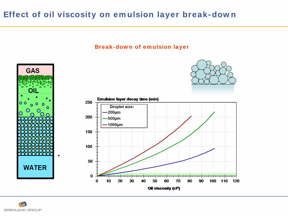
Effect of oil viscosity on emulsion layer break-down
Break-down of emulsion layer

Gas bubbles in emulsion band counteract break down of emulsion layer and separation
0
20
40
60
80
100
0 20 40 60 80 100
Watercut (%)
Wat
er s
epar
ated
with
in 4
min OW separation
GOW separation
Why is gas entrained into the oil/water phase?
GG
O/W
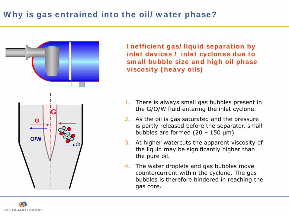
1. There is always small gas bubbles present in the G/O/W fluid entering the inlet cyclone.
2. As the oil is gas saturated and the pressure is partly released before the separator, small bubbles are formed (20 – 150 µm)
3. At higher watercuts the apparent viscosity of the liquid may be significantly higher than the pure oil.
4. The water droplets and gas bubbles move countercurrent within the cyclone. The gas bubbles is therefore hindered in reaching the gas core.
Inefficient gas/liquid separation by inlet devices / inlet cyclones due to small bubble size and high oil phase viscosity (heavy oils)
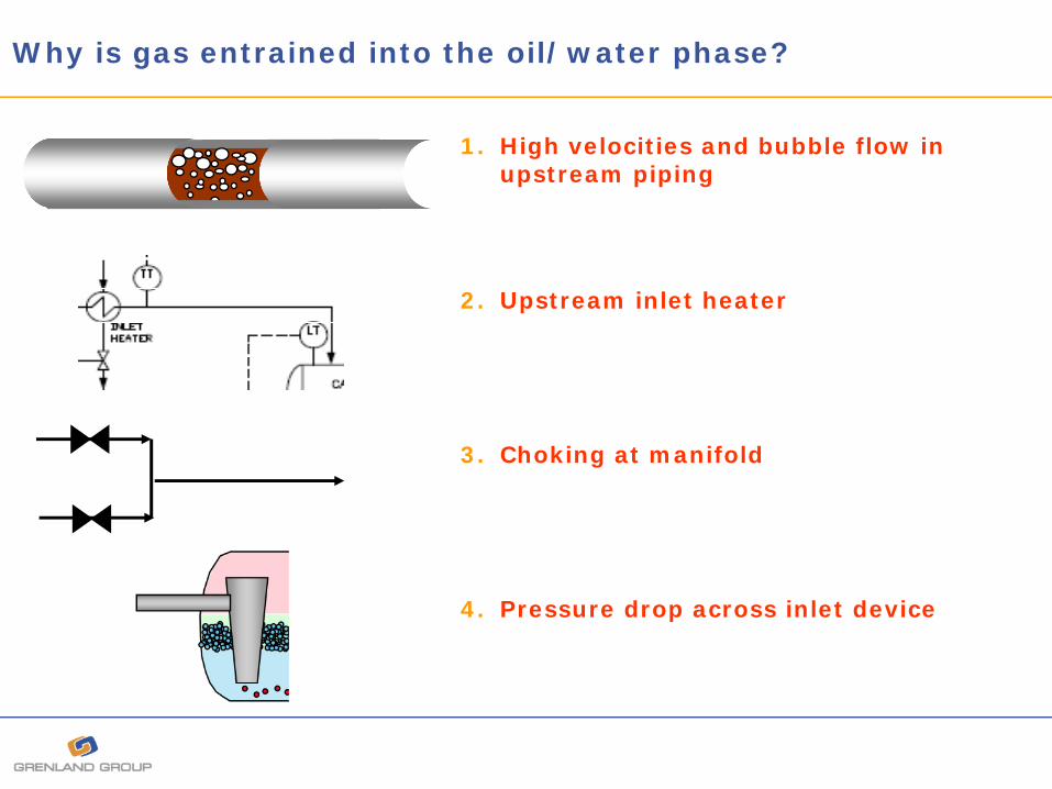
Why is gas entrained into the oil/water phase?
1. High velocities and bubble flow in upstream piping
2. Upstream inlet heater
3. Choking at manifold
4. Pressure drop across inlet device

Bubble flow in the upstream piping
Size of dispersed bubbles in bubble flow regime.
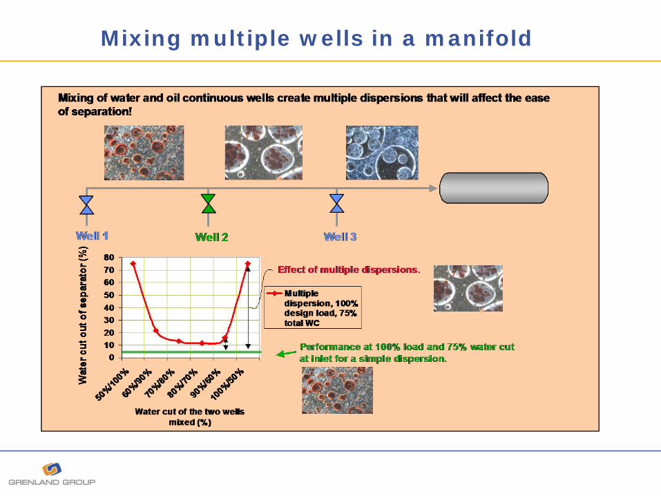
Mixing multiple wells in a manifold

Conclusions
Evaluate chemicals and required dosage level at realistic process conditions.Be careful trying to assess the separation properties of a given crude oil based on operational experience from a given gravity separator.The separability reflects the fluid itself, but also the upstream system and the actual separator design.
For more viscous crude oils both viscosity and droplet stability has to be adjusted in order to attain optimal separation.Be careful avoiding gas bubbles in dense packed droplet layer when designing the separator.Avoid or control multiple dispersions.

Thank You !


