Embed Size (px)
Citation preview

Carrier’s 16DEH steam-fired double effect, hermetic absorption liquid chiller provide an alternative means of efficient, cost effective water chilling. By utilizing high-pressure steam, 16DEH chillers avoid high-cost electricity and quality for utility rebates and incentives as a gas cooling product.
• no CFCs; environmentally friendly
• two-stage high efficiency design reduces energy costs
• quiet. vibration-free operation
• few moving parts equates to high reliability
Features/Benefits
High-pressure steam-fired
absorption reduces energy
costs, providing economical
water chilling and/or process
cooling.
Cost-effective cooling
Alternative-energy chiller
– The 16DEH offers an alternative to
chillers driven by increasingly
expensive electrical energy. The use of
steam-powered absorption not only
eliminates demand charges and high
cost electrical usage, but also allows the
owner to take advantage of gas cooling
rebates and incentive programs offered
by many utility companies. The 16DEH
is therefore economical to own and
operate compared to other types of
chillers. High-efficiency, double-effect
absorption cycle increases
efficiency – The 16DEH design
incorporates a high-temperature
generator and a low-temperature
generator (double effect) that provide 2
stages of solution re-concentration and
adds a drain heat exchanger and
condensate heat exchanger to recover
16DEH 20% Energy Saving Model, Steam-Fired,
Double Effect, Hermetic Absorption
Liquid Chiller
150 to 1650 Nominal Tons (527 to 5802 kW)
Product
Data
Copyright 2009 Carrier China Operations
16D16D16D16DEEEEHHHH
2
heat. The 16DEH use brazed plate heat
exchanger to get high efficiency than
16DE. As a result of this high efficiency
double-effect cycle, the 16DEH has
lower operating costs than single-effect
and common double-effect machines.
The 16DEH chiller offers typical full
load steam rates of less than 8.9 lb/hr-
ton at standard ARI (Air Conditioning
and Refrigeration Institute) operating
conditions.
Superior part-load performance –
The 16DEH’s standard concentration
control system allows stable, part-load
operation at cooling water temperatures
as low as 59 F (15 C) without the need
for a cooling tower bypass. For
maximum efficiency, a variable
frequency drive pump automatically
maintains optimum solution flow to the
high- and low-stage generators at all
operating conditions. This will result in
improved part-load efficiency and
eliminate the need for manual setup
adjustments of the solution flow.
High-efficiency condensate drain
heat exchanger saves energy –
Every 16DEH incorporates a condensate
drain heat exchanger which reduces steam
consumption, resulting in further energy
savings. Valuable energy (in the form of
heat) in the condensate leaving the
generator is transferred to the weak
lithium bromide solution as it is pumped
to the generator. This reduces the amount
of energy required to operate the chiller at
both full and part-load
Application versatility Ideal for new or retrofit applica-
tions – From comfort cooling to
providing chilled water for process
applications, the 16DEH double-effect
high-efficiency absorption chiller offers
versatility for almost any job where high-
pressure steam is available as the heat
source. The 12 model sizes, spanning a
capacity range of 150 to 1650 tons,
make the 16DEH double effect, high-
efficiency absorption chiller the ideal
choice for comfort cooling and /or light
industrial applications.
Carrier’s computerized performance
ratings assist in the selection of the
correct size machine to meet exact job
requirements. Dependable operation, as
well as low sound and vibration levels,
ensures occupant comfort, even when
Combined use of absorption and electric-driven chillers – Utilizing
both absorption and electric chillers in a
central plant offers the flexibility to base
load one chiller, while using the other to
handle peak load requirements. Hybrid
chiller systems have proven to be an
economical solution for many comfort
cooling installations. In many
geographical areas, operating the
electric chiller as the base loaded
machine, while using the absorption
chiller during peak load conditions,
reduces or avoids electric demand
charges. Depending on utility rate
structures, the 16DEH absorption chiller
used in conjunction with an electric-
driven chiller may be the most efficient
and cost-effective combination available.
Table of contents Page
Features/Benefits ………………………………………………………………..…1-8
Model Number Nomenclature………………………………………………………..2
Options and Accessories………………………………………………………… …..9
Machine Components……………………………………………………………….9
Physical Data…………………………………………………………………… 10-11
Dimensions……………………………………………………………………….…12
Performance Data………………………………………………………………..13-15
Application Data………………………………...……………………………….16-17
Controls……………….…………………………………………………………18-21
Guide Specifications…………………………………………………….……… 22-27
Model number nomenclature 16 DEH 033
Direct-Fired Double Effect High COP
Unit Size Absorption Chiller

3
Location and installation savings
Ease of installation – All 16DEH units are completely
fabricated, assembled, and wired in the factory as single-piece
units. Standard shipping configuration is 1 piece. Refer to the
16DEH Standard Shipping Configuration table below.
16DEH STANDARD SHIPPING CONFIGURATION
UNIT SIZE
1-PIECE ASSEMBLY
2-PIECE ASSEMBLY
015-120 X
135-165 X
The 16DEH015-120 machines are shipped completely
assembled as a standard feature with an option for 2-piece
shipment and the 16DEH135-165 machines are shipped by 2-
piece. The 2-piece is ideal for retrofit or replacement
installations where access into the equipment room may be
limited. Job-site reassembly and alignment of machines
shipped in multiple sections is simplified by pre-erecting the
machine in the factory and by incorporating weld-type
assembly flanges on all interconnecting piping.
Flanged water box nozzles – To simplify chiller
installation and field piping, all water box nozzles on the
evaporator, absorber, and condenser are factory-supplied raised
face (RF) flanges.
PD5 control features/benefits Chilled water reset – Reset can be accomplished manually
or automatically from the building management system.
Chilled water reset saves energy when warmer chilled water
can be used.
Ramp loading – Ramp loading ensures a smooth pulldown
of water loop temperature and prevents a rapid increase in
steam consumption.
Variable Frequency Drive (VFD) – PD5 provides VFD
for solution pump control.
Advanced crystallization protection – Protects against
crystallization by automatically sensing impending
abnormalities in the absorption operating cycle and taking a
series of actions to either self-correct and/or limit the chiller
from approaching the cycle crystallization line.
Absorption cycle state points – Absorption cycle status
points provide the operator with precise and dynamic cycle
operating conditions at any time during chiller operation. They
save time by eliminating the cumbersome task of taking
solution samples and calculating state points and assist in both
chiller operation and diagnostics.
Refrigerant low temperature override – The capacity
control valve position is inhibited to prevent freeze-up and
ensure continuous chiller operation.
Extensive service menu – Unauthorized access to the
service menu can be password-protected. Built-in, enhanced,
diagnostic capabilities assist in troubleshooting and
recommend proper corrective action for pre-set alarms,
resulting in more up time.
Alarm history – The last 25 alarms and/or alerts are retained
in memory with date and time stamps. Alarm histories reduce
troubleshooting time and cost.
TYPICAL 16DEH 1-PIECE SHIPMENT
4
Low maintenance
Standard features allow simple maintenance
procedures –Every 16DEH machine has numerous standard
design features that provide for convenient and simple
maintenance. Hinged waterbox cover on the absorber, and
condenser facilitate tube and waterbox inspection. In addition,
epoxy coating of the waterboxes and covers, standard on all
machines, protects against corrosion and extends machine life.
All moving parts are easily accessible for inspection or
replacement, as required.
Factory-trained service organization – Carrier’s
extensive service organization offers trained and experienced
service technicians in every major city. In addition to routine
maintenance and repair services, Carrier also offers a wide
array of preventative maintenance, full maintenance, and/or
extended service contracts that can be custom tailored to any
level of service.
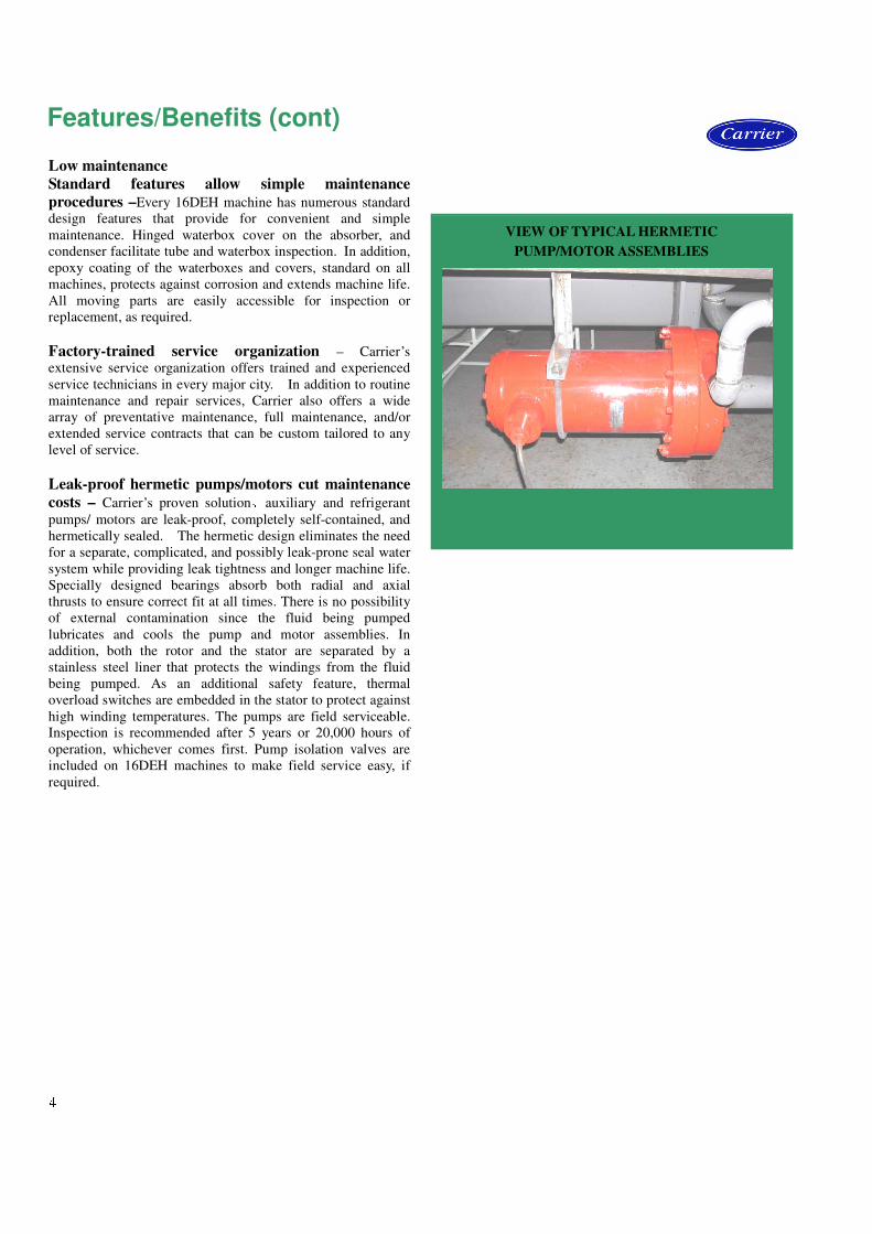
Leak-proof hermetic pumps/motors cut maintenance
costs – Carrier’s proven solution、auxiliary and refrigerant
pumps/ motors are leak-proof, completely self-contained, and
hermetically sealed. The hermetic design eliminates the need
for a separate, complicated, and possibly leak-prone seal water
system while providing leak tightness and longer machine life.
Specially designed bearings absorb both radial and axial
thrusts to ensure correct fit at all times. There is no possibility
of external contamination since the fluid being pumped
lubricates and cools the pump and motor assemblies. In
addition, both the rotor and the stator are separated by a
stainless steel liner that protects the windings from the fluid
being pumped. As an additional safety feature, thermal
overload switches are embedded in the stator to protect against
high winding temperatures. The pumps are field serviceable.
Inspection is recommended after 5 years or 20,000 hours of
operation, whichever comes first. Pump isolation valves are
included on 16DEH machines to make field service easy, if
required.
Features/Benefits (cont) VIEW OF TYPICAL HERMETIC
PUMP/MOTOR ASSEMBLIES
5
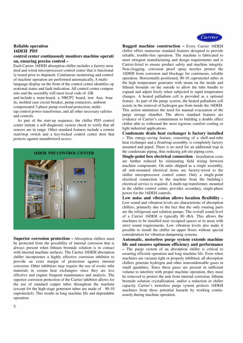
Reliable operation
16DEH PD5
control center continuously monitors machine operati
on, ensuring precise control –Each Carrier 16DEH absorption chiller includes a factory mou
nted and wired microprocessor control center that is functional
ly tested prior to shipment. Continuous monitoring and control
of machine operation are performed automatically. A multi-
language display on the front of the control center identifies op
erational status and fault indication. All control center compon
ents and the assembly will meet local code of GB
and include a main board, a NRCP2 board, tow Aux. boar
ds, molded case circuit breaker, pump contactors, ambient
compensated 3-phase pump overload protection, multi-
tap control power transformer, and all other necessary safeties
and controls. As part of the start-up sequence, the chiller PD5 control
center initiate a self-diagnostic system check to verify that all
sensors are in range. Other standard features include a remote
start/stop switch and a key-locked control center door that
protects against unauthorized access.
Superior corrosion protection – Absorption chillers must
be protected from the possibility of internal corrosion that is
always present when lithium bromide solution is in contact
with internal machine surfaces. The Carrier 16DEH absorption
chiller incorporates a highly effective corrosion inhibitor to
provide an extra margin of protection against internal
corrosion. Other inhibitors may require the use of exotic tube
materials in certain heat exchangers since they are less
effective and require frequent maintenance and analysis. The
superior corrosion protection of the Carrier inhibitor allows for
the use of standard copper tubes throughout the machine
(except for the high-stage generator tubes are made of 90-10
cupronickel). This results in long machine life and dependable
operation.
Rugged machine construction – Every Carrier 16DEH
chiller offers numerous standard features designed to provide
reliable, trouble-free operation. The machine is fabricated to
meet stringent manufacturing and design requirements and is
Carrier-listed to ensure product safety and machine integrity.
Non-clogging, corrosion proof spray nozzles protect the
16DEH from corrosion and blockage for continuous, reliable
operation. Horizontally-positioned, 90-10 cupronickel tubes in
the high temperature generator with steam on the inside and
lithium bromide on the outside to allow the tube bundle to
expand and adjust freely when subjected to rapid temperature
changes. A heated palladium cell is provided as a optional
feature. As part of the purge system, the heated palladium cell
assists in the removal of hydrogen gas from inside the 16DEH.
This action minimizes the need for manual evacuation of the
purge storage chamber. The above standard features are
evidence of Carrier’s commitment to building a double effect
chiller able to withstand the most rigorous comfort cooling or
light industrial applications.
Condensate drain heat exchanger is factory installed
– This energy-saving feature, consisting of a shell-and-tube
heat exchanger and a float/trap assembly, is completely factory
mounted and piped. There is no need for an additional trap in
the condensate piping, thus reducing job site piping costs.
Single-point box electrical connection – Installation costs
are further reduced by eliminating field wiring between
machine components. On units shipped as a single assembly,
all unit-mounted electrical items are factory-wired to the
chiller microprocessor control center. Only a single-point
electrical connection to the machine from the building’s
electrical service is required. A multi-tap transformer, mounted
in the chiller control center, provides secondary, single-phase
power for the 16DEH controls.
Low noise and vibration allows location flexibility –
Low sound and vibration levels are characteristic of absorption
chillers, primarily due to the fact that the only rotating parts
are the refrigerant and solution pumps. The overall sound level
of a Carrier 16DEH is typically 80 dbA. This allows the
machines to be installed near occupied spaces or in areas with
strict sound requirements. Low vibration levels also make it
possible to install the chiller on upper floors without special
consideration for vibration dampening systems.
Automatic, motorless purge system extends machine
life and ensures optimum efficiency and performance – The purge system of an absorption chiller is critical to
ensuring efficient operation and long machine life. Even when
machines are vacuum tight or properly inhibited, all absorption
chillers generate hydrogen and other noncondensable gases in
small quantities. Since these gases are present in sufficient
volume to interfere with proper machine operation, they must
be removed to protect the unit from internal corrosion, lithium
bromide solution crystallization, and/or a reduction in chiller
capacity. Carrier’s motorless purge system protects 16DEH
machines from these potential hazards by working contin-
uously during machine operation.
16DEH PD5 CONTROL CENTER
6
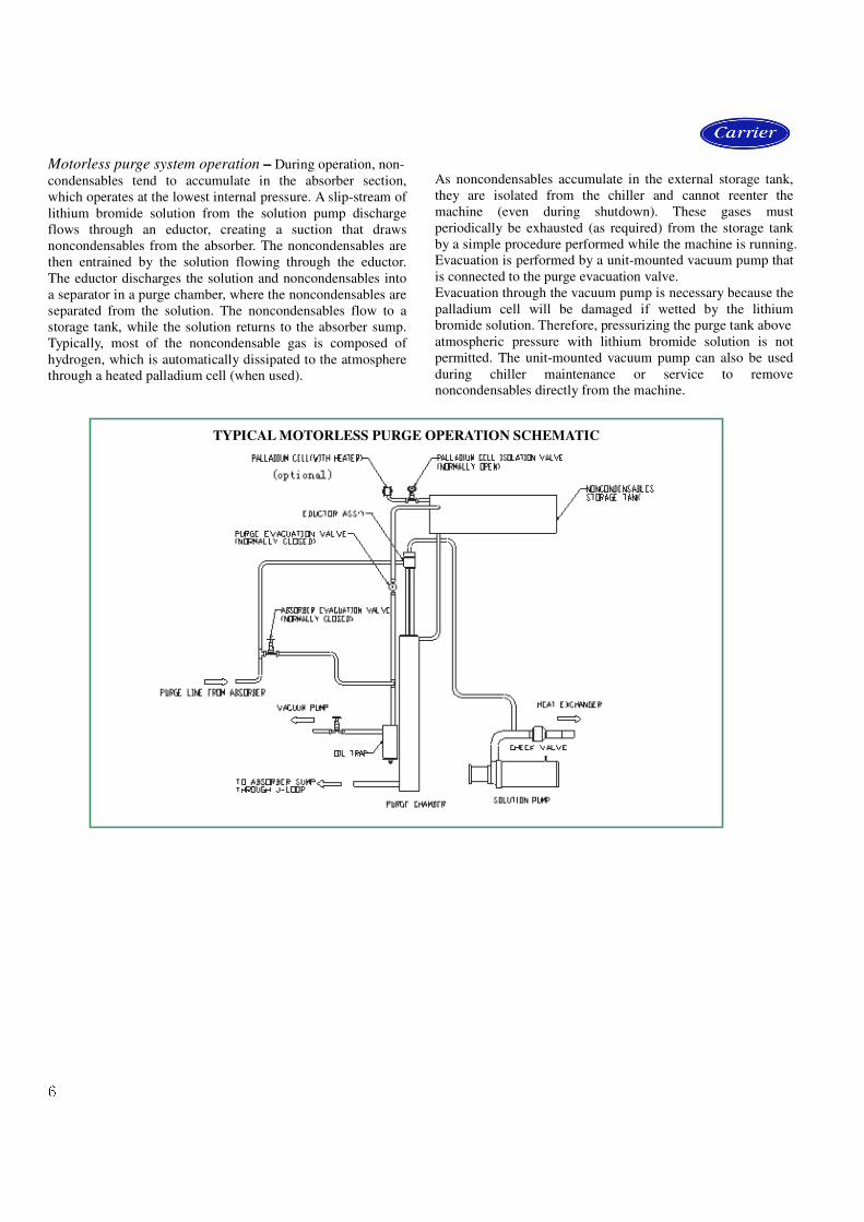
Motorless purge system operation – During operation, non-
condensables tend to accumulate in the absorber section,
which operates at the lowest internal pressure. A slip-stream of
lithium bromide solution from the solution pump discharge
flows through an eductor, creating a suction that draws
noncondensables from the absorber. The noncondensables are
then entrained by the solution flowing through the eductor.
The eductor discharges the solution and noncondensables into
a separator in a purge chamber, where the noncondensables are
separated from the solution. The noncondensables flow to a
storage tank, while the solution returns to the absorber sump.
Typically, most of the noncondensable gas is composed of
hydrogen, which is automatically dissipated to the atmosphere
through a heated palladium cell (when used).
As noncondensables accumulate in the external storage tank,
they are isolated from the chiller and cannot reenter the
machine (even during shutdown). These gases must
periodically be exhausted (as required) from the storage tank
by a simple procedure performed while the machine is running.
Evacuation is performed by a unit-mounted vacuum pump that
is connected to the purge evacuation valve.
Evacuation through the vacuum pump is necessary because the
palladium cell will be damaged if wetted by the lithium
bromide solution. Therefore, pressurizing the purge tank above
atmospheric pressure with lithium bromide solution is not
permitted. The unit-mounted vacuum pump can also be used
during chiller maintenance or service to remove
noncondensables directly from the machine.
TYPICAL MOTORLESS PURGE OPERATION SCHEMATIC

7
Anti-crystallization controls maintain proper solution
concentration – The 16DEH automatically limits solution
concentration in several ways to avoid both crystallization and
overdilution to provide dependable, trouble-free operation.
Crystallization of the lithium bromide solution depends on the
combination of temperature and concentration. Carrier’s
concentration control system automatically monitors the
refrigerant water level in the evaporator in conjunction with
the solution temperature returning to the absorber. Because
concentration varies with the amount of water in the lithium
bromide solution, a rising evaporator level indicates less water
in the solution and thus a higher solution concentration. When
the refrigerant in the evaporator rises to a weir level, water is
transferred from the evaporator to the absorber thus preventing
overconcentration to ensure continuous, reliable operation
even at cooling water temperature as low as 59 F (15 C).
Overdilution (and possible refrigerant pump cavitation) shall
be controlled by transferring an additional amount of
refrigerant from the condenser to the evaporator.
The 16DEH also incorporates a simple, passive method of
control to correct any crystallization that would typically start
to occur on the shell-side of the low temperature solution heat
exchanger under abnormal conditions. As the hot solution
begins to back up in the generator, as a result of any shell-side
blockage, it rises above the overflow pipe and returns directly
to the absorber. It is subsequently pumped through the tube-
side (heating the shell-side) to restore proper operation.
In addition, the 16DEH automatic dilution cycle ensures
proper concentration after unit shutdown so that the unit will
not crystallize when the machine cools to ambient or machine
room temperature. The dilution cycle controls operation of the
pumps for a set period of time after shutdown to dilute the
solution to prevent an overconcentration condition.
16DEH double effect absorption cooling cycle – The
16DEH double effect absorption chiller consists of an
evaporator, absorber, condenser, high- and low-stage
generators, solution heat exchangers(BPHE), steam condensate
drain heat exchanger, refrigerant/solution/auxiliary pumps,
purge, controls and auxiliaries. Water is used as the refrigerant
in vessels maintained under low absolute pressure (vacuum).
In the cooling mode, the chiller operates on the principle that
under vacuum, water boils at a low temperature. In this case
water boils at approximately 40 F (4.4 C), thereby cooling the
chilled water circulating through the evaporator tubes. A
refrigerant pump is used to circulate the refrigerant water over
the evaporator tubes to improve heat transfer.
To make the cooling process continuous, the refrigerant
vapor must be removed as it is produced. To accomplish this,
a lithium bromide solution (which has a high affinity for
water) is used to absorb the water vapor. As this process
continues, the lithium bromide becomes diluted, reducing its
absorption capacity. A solution pump then transfers this
weak (diluted) solution to the generators where it is recon-
centrated in 2 stages to boil off the previously absorbed water.
A variable frequency drive pump automatically maintains
optimum solution flow to the generators at all operating
conditions for maximum efficiency. The diluted solution is
pumped to the high-stage generator where it is heated and
reconcentrated to a medium concentration solution by the heat
from high pressure steam. The medium concentration solution
from the high-stage generator flows to the low-stage generator
where it is heated and reconcentrated to a strong solution by
the high temperature water vapor released from the solution in
the high-stage generator.
Since the low-stage generator acts as the condenser for the
high-stage generator, the heat energy first applied in the
16DEH ABSORPTION COOLING CYCLE
Diaphragm
Valve

8
high-stage generator is used again in the low-stage generator
thus reducing the heat input by approximately 45% as
compared to an absorption chiller with a single stage of
reconcentration. The water vapor released in the shell-side of
the low-stage generator, in addition to the now condensed
water vapor from the tube-side of the low-stage generator,
enters the condenser to be cooled and returned to a liquid state.
The refrigerant water then returns to the evaporator to begin a
new cycle.
To remove heat from the machine, relatively cool water
from a cooling tower or other source is first circulated through
the tubes of the absorber to remove the heat of vaporization.
The water is then circulated through the tubes of the condenser.
The strong (reconcentrated) solution from the low-stage
generator flows back to the absorber to begin a new cycle
. For efficiency reasons, the medium concentration solution
from the high-stage generator is passed through the high-
temperature solution heat exchanger to pre-heat the weak
solution, while pre-cooling the medium concentration solution.
The strong solution from the low-stage generator is passed
through the low-temperature solution heat exchanger to pre-
cool the strong solution before being returned to the absorber.
The efficiency is further improved by use of two additional
components. One is a condensate drain heat exchanger which
transfers additional heat from the steam condensate leaving
high-stage generator to the weak solution, another is a
condensate heat exchanger which transfers additional heat
from the vapor condensate leaving low-stage generator to the
weak solution
Features/Benefits (cont)
9
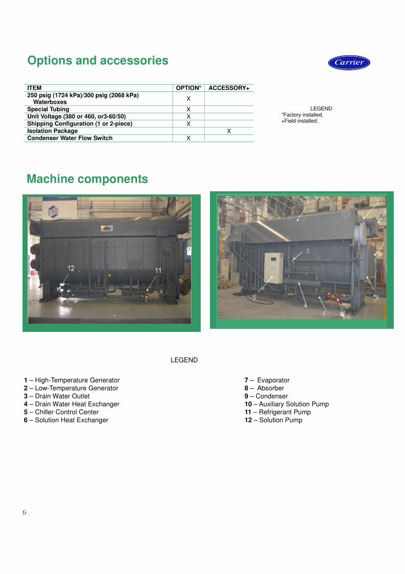
9Machine components
LEGEND *Factory installed. +Field installed. ITEM OPTION* ACCESSORY+
250 psig (1724 kPa)/300 psig (2068 kPa) Waterboxes
X
Special Tubing X Unit Voltage (380 or 460, or3-60/50) X Shipping Configuration (1 or 2-piece) X Isolation Package X Condenser Water Flow Switch X
Options and accessories
1 – High-Temperature Generator
2 – Low-Temperature Generator
3 – Drain Water Outlet
4 – Drain Water Heat Exchanger
5 – Chiller Control Center
6 – Solution Heat Exchanger
7 – Evaporator
8 – Absorber
9 – Condenser
10 – Auxiliary Solution Pump
11 – Refrigerant Pump
12 – Solution Pump
LEGEND
10
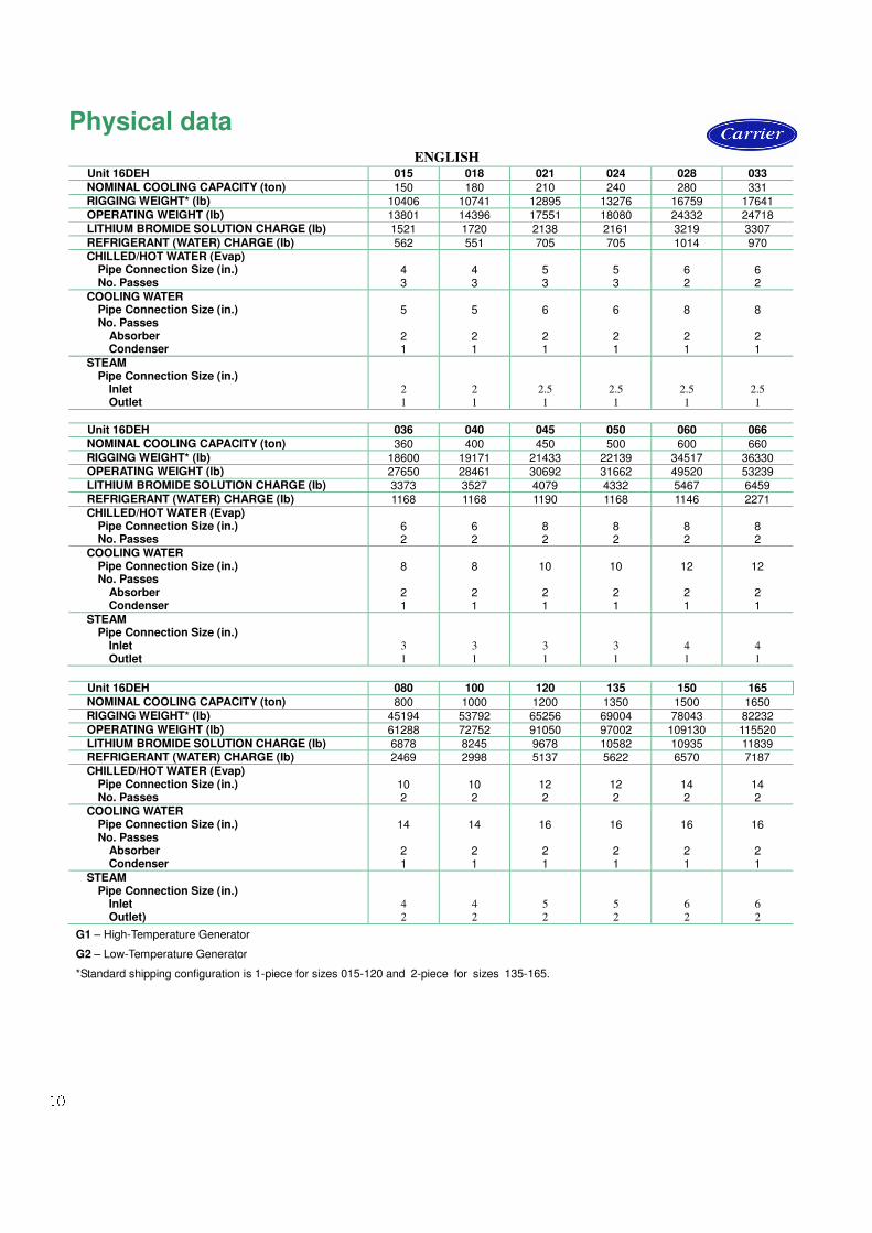
Physical data ENGLISH
Unit 16DEH 015 018 021 024 028 033 NOMINAL COOLING CAPACITY (ton) 150 180 210 240 280 331
RIGGING WEIGHT* (lb) 10406 10741 12895 13276 16759 17641 OPERATING WEIGHT (lb) 13801 14396 17551 18080 24332 24718 LITHIUM BROMIDE SOLUTION CHARGE (Ib) 1521 1720 2138 2161 3219 3307 REFRIGERANT (WATER) CHARGE (Ib) 562 551 705 705 1014 970
CHILLED/HOT WATER (Evap) Pipe Connection Size (in.) No. Passes
4 3
4 3
5 3
5 3
6 2
6 2
COOLING WATER Pipe Connection Size (in.) No. Passes Absorber Condenser
5 2 1
5 2 1
6 2 1
6 2 1
8 2 1
8 2 1
STEAM Pipe Connection Size (in.) Inlet Outlet
2
1
2
1
2.5
1
2.5
1
2.5
1
2.5
1
Unit 16DEH 036 040 045 050 060 066
NOMINAL COOLING CAPACITY (ton) 360 400 450 500 600 660 RIGGING WEIGHT* (lb) 18600 19171 21433 22139 34517 36330
OPERATING WEIGHT (lb) 27650 28461 30692 31662 49520 53239 LITHIUM BROMIDE SOLUTION CHARGE (Ib) 3373 3527 4079 4332 5467 6459 REFRIGERANT (WATER) CHARGE (Ib) 1168 1168 1190 1168 1146 2271
CHILLED/HOT WATER (Evap) Pipe Connection Size (in.) No. Passes
6 2
6 2
8 2
8 2
8 2
8 2
COOLING WATER Pipe Connection Size (in.) No. Passes Absorber Condenser
8 2 1
8 2 1
10 2 1
10 2 1
12 2 1
12 2 1
STEAM Pipe Connection Size (in.) Inlet Outlet
3
1
3
1
3
1
3
1
4
1
4
1 Unit 16DEH 080 100 120 135 150 165
NOMINAL COOLING CAPACITY (ton) 800 1000 1200 1350 1500 1650 RIGGING WEIGHT* (lb) 45194 53792 65256 69004 78043 82232
OPERATING WEIGHT (lb) 61288 72752 91050 97002 109130 115520 LITHIUM BROMIDE SOLUTION CHARGE (Ib) 6878 8245 9678 10582 10935 11839 REFRIGERANT (WATER) CHARGE (Ib) 2469 2998 5137 5622 6570 7187
CHILLED/HOT WATER (Evap) Pipe Connection Size (in.) No. Passes
10 2
10 2
12 2
12 2
14 2
14 2
COOLING WATER Pipe Connection Size (in.) No. Passes Absorber Condenser
14 2 1
14 2 1
16 2 1
16 2 1
16 2 1
16 2 1
STEAM Pipe Connection Size (in.) Inlet Outlet)
4
2
4
2
5
2
5
2
6
2
6
2
G1 – High-Temperature Generator
G2 – Low-Temperature Generator
*Standard shipping configuration is 1-piece for sizes 015-120 and 2-piece for sizes 135-165.
11
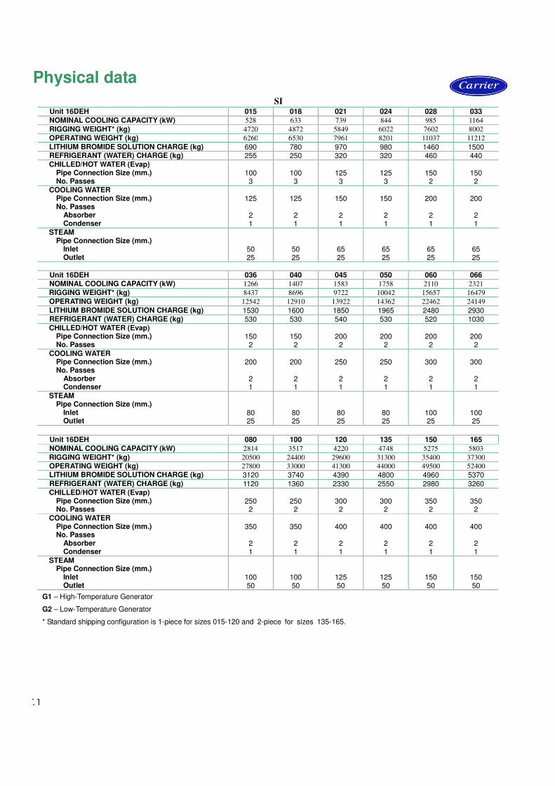
Physical data SI
Unit 16DEH 015 018 021 024 028 033
NOMINAL COOLING CAPACITY (kW) 528 633 739 844 985 1164
RIGGING WEIGHT* (kg) 4720 4872 5849 6022 7602 8002
OPERATING WEIGHT (kg) 6260 6530 7961 8201 11037 11212
LITHIUM BROMIDE SOLUTION CHARGE (kg) 690 780 970 980 1460 1500 REFRIGERANT (WATER) CHARGE (kg) 255 250 320 320 460 440
CHILLED/HOT WATER (Evap) Pipe Connection Size (mm.) No. Passes
100 3
100 3
125 3
125 3
150 2
150 2
COOLING WATER Pipe Connection Size (mm.) No. Passes Absorber Condenser
125
2 1
125
2 1
150
2 1
150
2 1
200
2 1
200
2 1
STEAM Pipe Connection Size (mm.) Inlet Outlet
50 25
50 25
65 25
65 25
65 25
65 25
Unit 16DEH 036 040 045 050 060 066
NOMINAL COOLING CAPACITY (kW) 1266 1407 1583 1758 2110 2321
RIGGING WEIGHT* (kg) 8437 8696 9722 10042 15657 16479
OPERATING WEIGHT (kg) 12542 12910 13922 14362 22462 24149
LITHIUM BROMIDE SOLUTION CHARGE (kg) 1530 1600 1850 1965 2480 2930 REFRIGERANT (WATER) CHARGE (kg) 530 530 540 530 520 1030
CHILLED/HOT WATER (Evap) Pipe Connection Size (mm.) No. Passes
150 2
150 2
200 2
200 2
200 2
200 2
COOLING WATER Pipe Connection Size (mm.) No. Passes Absorber Condenser
200
2 1
200
2 1
250
2 1
250
2 1
300
2 1
300
2 1
STEAM Pipe Connection Size (mm.) Inlet Outlet
80 25
80 25
80 25
80 25
100 25
100 25
Unit 16DEH 080 100 120 135 150 165
NOMINAL COOLING CAPACITY (kW) 2814 3517 4220 4748 5275 5803
RIGGING WEIGHT* (kg) 20500 24400 29600 31300 35400 37300
OPERATING WEIGHT (kg) 27800 33000 41300 44000 49500 52400
LITHIUM BROMIDE SOLUTION CHARGE (kg) 3120 3740 4390 4800 4960 5370 REFRIGERANT (WATER) CHARGE (kg) 1120 1360 2330 2550 2980 3260
CHILLED/HOT WATER (Evap) Pipe Connection Size (mm.) No. Passes
250 2
250 2
300 2
300 2
350 2
350 2
COOLING WATER Pipe Connection Size (mm.) No. Passes Absorber Condenser
350
2 1
350
2 1
400
2 1
400
2 1
400
2 1
400
2 1
STEAM Pipe Connection Size (mm.) Inlet Outlet
100 50
100 50
125 50
125 50
150 50
150 50
G1 – High-Temperature Generator
G2 – Low-Temperature Generator
* Standard shipping configuration is 1-piece for sizes 015-120 and 2-piece for sizes 135-165.
12
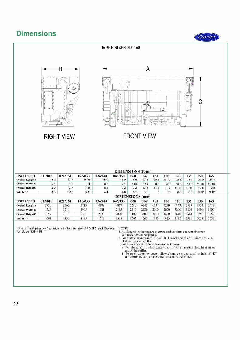
Dimensions 16DEH SIZES 015-165
DIMENSIONS (ft-in.)
UNIT 16DEH 015/018 021/024 028/033 036/040 045/050 060 066 080 100 120 135 150 165 Overall LengthA 12-2 12-4 15-10 15-9 16-0 18-6 20-2 20-6 23-10 22-5 24-1 22-9 24-4
Overall Width B 5-1 5-7 6-3 6-6 7-1 7-10 7-10 8-6 8-6 10-8 10-8 11-10 11-10
Overall HeightC 6-9 7-7 7-10 8-8 9-3 10-2 10-2 11-2 11-2 11-11 11-11 12-8 12-8
Width D* 3-3 3-10 3-11 4-4 4-6 5-1 5-1 6 6 8-6 8-6 9-12 9-12
DIMENSIONS (mm) UNIT 16DEH 015/018 021/024 028/033 036/040 045/050 060 066 080 100 120 135 150 165 Overall LengthA 3720 3762 4815 4798 4867 5640 6142 6244 7259 6843 7333 6924 7413
Overall Width B 1556 1714 1905 1981 2165 2386 2386 2600 2600 3260 3260 3600 3600
Overall HeightC 2057 2310 2381 2630 2820 3102 3102 3400 3400 3640 3640 3850 3850
Width D* 1002 1156 1195 1318 1368 1562 1562 1823 1823 2582 2582 3038 3038
*Standard shipping configuration is 1-piece for sizes 015-120 and 2-piece for sizes 135-165.
NOTES: 1. All dimensions in mm are accurate and take into account absorber-
condenser crossover piping. 2. For routine maintenance, allow 3 ft (1 m) clearance on all sides and 6 in.
(150 mm) above chiller. 3. For service access, allow clearance as follows: a. For tube removal, allow space equal to “A” dimension (length) at either end of the chiller.
b. To open waterbox cover, allow clearance space equal to half of “D” dimension (width) on the waterbox end of the chiller.
13
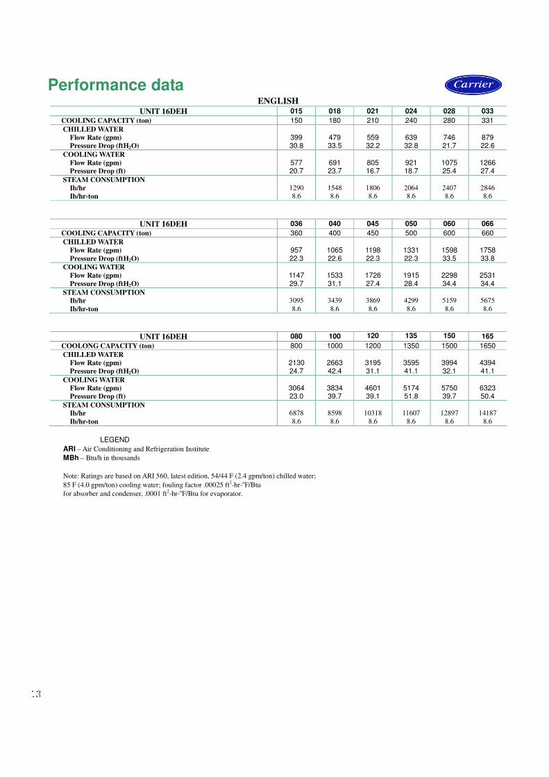
Performance data ENGLISH
UNIT 16DEH 015 018 021 024 028 033
COOLING CAPACITY (ton) 150 180 210 240 280 331
CHILLED WATER
Flow Rate (gpm)
Pressure Drop (ftH2O)
399 30.8
479 33.5
559 32.2
639 32.8
746 21.7
879 22.6
COOLING WATER
Flow Rate (gpm)
Pressure Drop (ft)
577 20.7
691 23.7
805 16.7
921 18.7
1075 25.4
1266 27.4
STEAM CONSUMPTION
Ib/hr
Ib/hr-ton
1290
8.6
1548
8.6
1806
8.6
2064
8.6
2407
8.6
2846
8.6
UNIT 16DEH 036 040 045 050 060 066
COOLING CAPACITY (ton) 360 400 450 500 600 660
CHILLED WATER
Flow Rate (gpm)
Pressure Drop (ftH2O)
957 22.3
1065 22.6
1198 22.3
1331 22.3
1598 33.5
1758 33.8
COOLING WATER
Flow Rate (gpm)
Pressure Drop (ftH2O)
1147 29.7
1533 31.1
1726 27.4
1915 28.4
2298 34.4
2531 34.4
STEAM CONSUMPTION
Ib/hr
Ib/hr-ton
3095
8.6
3439
8.6
3869
8.6
4299
8.6
5159
8.6
5675
8.6
UNIT 16DEH 080 100 120 135 150 165
COOLONG CAPACITY (ton) 800 1000 1200 1350 1500 1650
CHILLED WATER
Flow Rate (gpm)
Pressure Drop (ftH2O)
2130 24.7
2663 42.4
3195 31.1
3595 41.1
3994 32.1
4394 41.1
COOLING WATER
Flow Rate (gpm)
Pressure Drop (ft)
3064 23.0
3834 39.7
4601 39.1
5174 51.8
5750 39.7
6323 50.4
STEAM CONSUMPTION
Ib/hr
Ib/hr-ton
6878
8.6
8598
8.6
10318
8.6
11607
8.6
12897
8.6
14187
8.6
LEGEND
ARI – Air Conditioning and Refrigeration Institute
MBh – Btu/h in thousands
Note: Ratings are based on ARI 560, latest edition, 54/44 F (2.4 gpm/ton) chilled water;
85 F (4.0 gpm/ton) cooling water; fouling factor .00025 ft2-hr-oF/Btu
for absorber and condenser, .0001 ft2-hr-oF/Btu for evaporator.
14
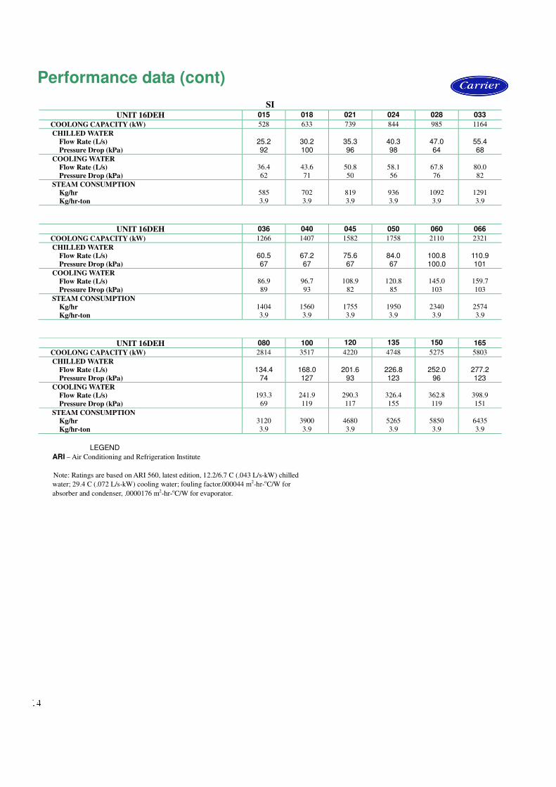
SI
UNIT 16DEH 015 018 021 024 028 033
COOLONG CAPACITY (kW) 528 633 739 844 985 1164
CHILLED WATER
Flow Rate (L/s)
Pressure Drop (kPa)
25.2 92
30.2 100
35.3 96
40.3 98
47.0 64
55.4 68
COOLING WATER
Flow Rate (L/s)
Pressure Drop (kPa)
36.4
62
43.6
71
50.8
50
58.1
56
67.8
76
80.0
82
STEAM CONSUMPTION
Kg/hr
Kg/hr-ton
585
3.9
702
3.9
819
3.9
936
3.9
1092
3.9
1291
3.9
UNIT 16DEH 036 040 045 050 060 066
COOLONG CAPACITY (kW) 1266 1407 1582 1758 2110 2321
CHILLED WATER
Flow Rate (L/s)
Pressure Drop (kPa)
60.5 67
67.2 67
75.6 67
84.0 67
100.8 100.0
110.9 101
COOLING WATER
Flow Rate (L/s)
Pressure Drop (kPa)
86.9
89
96.7
93
108.9
82
120.8
85
145.0
103
159.7
103
STEAM CONSUMPTION
Kg/hr
Kg/hr-ton
1404
3.9
1560
3.9
1755
3.9
1950
3.9
2340
3.9
2574
3.9
UNIT 16DEH 080 100 120 135 150 165
COOLONG CAPACITY (kW) 2814 3517 4220 4748 5275 5803
CHILLED WATER
Flow Rate (L/s)
Pressure Drop (kPa)
134.4
74
168.0 127
201.6
93
226.8 123
252.0
96
277.2 123
COOLING WATER
Flow Rate (L/s)
Pressure Drop (kPa)
193.3
69
241.9
119
290.3
117
326.4
155
362.8
119
398.9
151
STEAM CONSUMPTION
Kg/hr
Kg/hr-ton
3120
3.9
3900
3.9
4680
3.9
5265
3.9
5850
3.9
6435
3.9
LEGEND
ARI – Air Conditioning and Refrigeration Institute
Note: Ratings are based on ARI 560, latest edition, 12.2/6.7 C (.043 L/s-kW) chilled
water; 29.4 C (.072 L/s-kW) cooling water; fouling factor.000044 m2-hr-oC/W for
absorber and condenser, .0000176 m2-hr-oC/W for evaporator.
Performance data (cont)
15
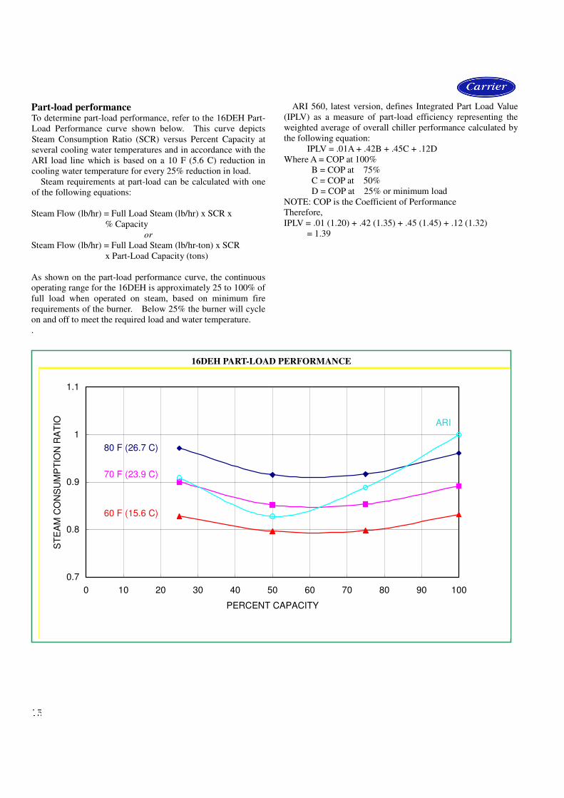
Part-load performance To determine part-load performance, refer to the 16DEH Part-
Load Performance curve shown below. This curve depicts
Steam Consumption Ratio (SCR) versus Percent Capacity at
several cooling water temperatures and in accordance with the
ARI load line which is based on a 10 F (5.6 C) reduction in
cooling water temperature for every 25% reduction in load.
Steam requirements at part-load can be calculated with one
of the following equations:
Steam Flow (lb/hr) = Full Load Steam (lb/hr) x SCR x
% Capacity
or
Steam Flow (lb/hr) = Full Load Steam (lb/hr-ton) x SCR
x Part-Load Capacity (tons)
As shown on the part-load performance curve, the continuous
operating range for the 16DEH is approximately 25 to 100% of
full load when operated on steam, based on minimum fire
requirements of the burner. Below 25% the burner will cycle
on and off to meet the required load and water temperature.
.
ARI 560, latest version, defines Integrated Part Load Value
(IPLV) as a measure of part-load efficiency representing the
weighted average of overall chiller performance calculated by
the following equation:
IPLV = .01A + .42B + .45C + .12D
Where A = COP at 100%
B = COP at 75%
C = COP at 50%
D = COP at 25% or minimum load
NOTE: COP is the Coefficient of Performance
Therefore,
IPLV = .01 (1.20) + .42 (1.35) + .45 (1.45) + .12 (1.32)
= 1.39
16DEH PART-LOAD PERFORMANCE
0.7
0.8
0.9
1
1.1
0 10 20 30 40 50 60 70 80 90 100
PERCENT CAPACITY
ST
EA
M C
ON
SU
MP
TIO
N R
AT
IO
80 F (26.7 C)
70 F (23.9 C)
60 F (15.6 C)
ARI
16
Vent and drain connections
Vent and drain connections All vents and drain connections are found on the waterbox
covers. Connection size is 3/4-in. PT.
Provide high points of the machine piping system with vents
and the low points with drains. If shut off valves are
provided in the main water pipes near the unit, a minimum
amount of the system water is lost when the heat exchangers
are drained.
It is recommended that pressure gages be provided at points
of entering and leaving water to measure pressure drop
through the heat exchanger. Gages may be installed as shown
in the table below. Pressure gages installed at the vent and
drain connections do not include nozzle pressure losses.
Use a reliable manometer to measure pressure differential
when determining water flow. Regular gages are insensitive
and do not provide accurate measurement of flow conditions.
NUMBER OF PASSES GAGE LOCATION
1, 3 One gage in each waterbox
2, 4 Two gages in waterbox with nozzles
Range of application The 16DEH absorption chiller is designed for standard water
chilling applications of 150 to 660 tons (528 to2321 kW) at
standard ARI rating conditions.
Rupture disk piping The 16DEH is equipped with a rupture disk or a fusible plug
(optional) on the high-temperature generator. It is
recommended that piping from these devices be routed to
appropriate areas away from the machine in accordance with
Carrier’s written installation instructions, and any local
jurisdictional requirements that may apply. One side of Ru
pture disk’s connective tube is connected with protected
recipient and another side is leaded to safe place such
as atmosphere or where there is no person. Piping should
be adequately supported and the proper fittings should be
provided to allow periodic inspection of the disk.
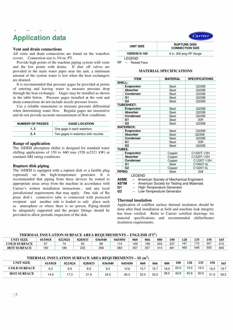
UNIT SIZE RUPTURE DISK
CONNECTION SIZE
16DEH015-165 6 in. 300 psig RF flange
LEGEND RF – Raised Face
MATERIAL SPECIFICATIONS
ITEM MATERIAL SPECIFICATIONS
SHELL:
Evaporator Steel Q235B
Absorber Steel Q235B
Condenser Steel Q235B
G1 Steel Q235B G2 Steel Q235B
TUBESHEET:
Evaporator Steel Q235B
Absorber Steel Q235B
Condenser Steel Q235B
G1 Steel 20R G2 Steel Q235B
WATERBOX:
Evaporator Steel Q235B
Absorber Steel Q235B
Condenser Steel Q235B
G1 Steel 20R G2 Steel Q235B
TUBES:
Evaporator Copper C1220T-1/2H
Absorber Copper C1220T-1/2H
Condenser Copper C1220T-1/2H
G1 Steel C7060T-0L G2 Copper C1220T-0L
PIPING Steel 20#
LEGEND ASME – American Society of Mechanical Engineers ASTM -- American Society for Testing and Materials G1 -- High-Temperature Generator G2 -- Low-Temperature Generator
Thermal insulation Application of cold/hot surface thermal insulation should be
done after final installation at field and machine leak integrity
has been verified. Refer to Carrier certified drawings for
material specifications and recommended chiller/heater
insulation requirements.
THERMAL INSULATION SURFACE AREA REQUIREMENTS – ENGLISH (FT2)
UNIT SIZE 015/018 021/024 028/033 036/040 045/050 060 066 080 100 120 135 150 165
COLD SURFACE 67 74 93 99 114 169 169 203 237 167 172 207 212
HOT SURFACE 160 186 233 258 283 357 357 414 461 493 548 555 605
THERMAL INSULATION SURFACE AREA REQUIREMENTS – SI (m2)
UNIT SIZE 015/018 021/024 028/033 036/040 045/050 060 066 080 100 120 135 150 165
COLD SURFACE 6.2 6.9 8.6 9.2 10.6 15.7 15.7 18.9 22.0 15.5 16.0 19.2 19.7
HOT SURFACE 14.9 17.3 21.6 24.0 26.3 33.2 33.2 38.5 42.8 45.8 50.9 51.6 56.2
Application data Application data
17
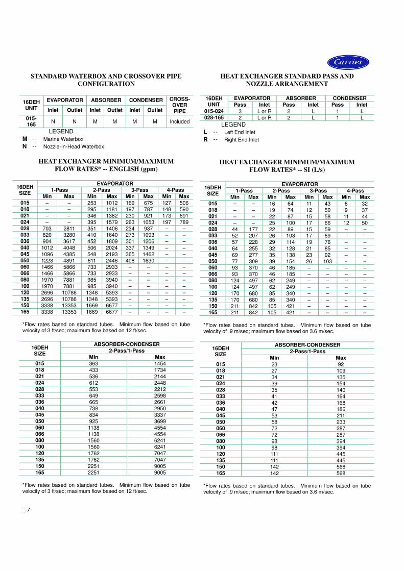
STANDARD WATERBOX AND CROSSOVER PIPE
CONFIGURATION
16DEH UNIT
EVAPORATOR ABSORBER CONDENSER CROSS- OVER PIPE Inlet Outlet Inlet Outlet Inlet Outlet
015- 165
N N M M M M Included
LEGEND
M -- Marine Waterbox N -- Nozzle-In-Head Waterbox
HEAT EXCHANGER MINIMUM/MAXIMUM
FLOW RATES* -- ENGLISH (gpm)
16DEH SIZE
EVAPORATOR 1-Pass 2-Pass 3-Pass 4-Pass
Min Max Min Max Min Max Min Max
015 – – 253 1012 169 675 127 506 018 – – 295 1181 197 787 148 590 021 – – 346 1382 230 921 173 691 024 – – 395 1579 263 1053 197 789 028 703 2811 351 1406 234 937 – – 033 820 3280 410 1640 273 1093 – – 036 904 3617 452 1809 301 1206 – – 040 1012 4048 506 2024 337 1349 – – 045 1096 4385 548 2193 365 1462 – – 050 1223 4891 611 2446 408 1630 – – 060 1466 5866 733 2933 – – – – 066 1466 5866 733 2933 – – – – 080 1970 7881 985 3940 – – – – 100 1970 7881 985 3940 – – – – 120 2696 10786 1348 5393 – – – – 135 2696 10786 1348 5393 – – – – 150 3338 13353 1669 6677 – – – – 165 3338 13353 1669 6677 – – – – *Flow rates based on standard tubes. Minimum flow based on tube velocity of 3 ft/sec; maximum flow based on 12 ft/sec.
16DEH SIZE
ABSORBER-CONDENSER 2-Pass/1-Pass
Min Max 015 363 1454 018 433 1734 021 536 2144 024 612 2448 028 553 2212 033 649 2598 036 665 2661 040 738 2950 045 834 3337 050 925 3699 060 1138 4554 066 1138 4554 080 1560 6241 100 1560 6241 120 1762 7047 135 1762 7047 150 2251 9005 165 2251 9005
*Flow rates based on standard tubes. Minimum flow based on tube velocity of 3 ft/sec; maximum flow based on 12 ft/sec.
HEAT EXCHANGER STANDARD PASS AND
NOZZLE ARRANGEMENT
16DEH UNIT
EVAPORATOR ABSORBER CONDENSER
Pass Inlet Pass Inlet Pass Inlet
015-024 3 L or R 2 L 1 L 028-165 2 L or R 2 L 1 L
LEGEND
L -- Left End Inlet R -- Right End Inlet
HEAT EXCHANGER MINIMUM/MAXIMUM
FLOW RATES* -- SI (L/s)
16DEH SIZE
EVAPORATOR
1-Pass 2-Pass 3-Pass 4-Pass Min Max Min Max Min Max Min Max
015 – – 16 64 11 43 8 32 018 – – 19 74 12 50 9 37 021 – – 22 87 15 58 11 44 024 – – 25 100 17 66 12 50 028 44 177 22 89 15 59 – – 033 52 207 26 103 17 69 – – 036 57 228 29 114 19 76 – – 040 64 255 32 128 21 85 – – 045 69 277 35 138 23 92 – – 050 77 309 39 154 26 103 – – 060 93 370 46 185 – – – – 066 93 370 46 185 – – – – 080 124 497 62 249 – – – – 100 124 497 62 249 – – – – 120 170 680 85 340 – – – – 135 170 680 85 340 – – – – 150 211 842 105 421 – – – – 165 211 842 105 421 – – – –
*Flow rates based on standard tubes. Minimum flow based on tube velocity of .9 m/sec; maximum flow based on 3.6 m/sec.
16DEH SIZE
ABSORBER-CONDENSER
2-Pass/1-Pass
Min Max
015 23 92 018 27 109 021 34 135 024 39 154 028 35 140 033 41 164 036 42 168 040 47 186 045 53 211 050 58 233 060 72 287 066 72 287 080 98 394 100 98 394 120 111 445 135 111 445 150 142 568 165 142 568
*Flow rates based on standard tubes. Minimum flow based on tube velocity of .9 m/sec; maximum flow based on 3.6 m/sec.
18
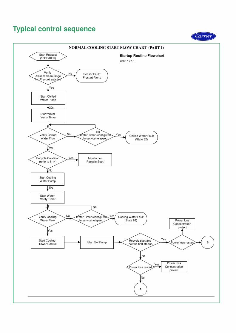
Typical control sequence NORMAL COOLING START FLOW CHART (PART 1)
Verify All sensors In rangeInc Prestart satisfies
Water Timer (configuredIn service) elapsed
Verify ChilledWater Flow
Verify CoolingWater Flow
Recycle Condition(refer to 5.14)
Start CoolingWater Pump
Start Water Verify Timer
Monitor forRecycle Start
Start Water Verify Timer
Start ChilledWater Pump
Start Request(16DE/DEH)
Start Sol PumpStart Cooling Tower Control
Cooling Water Fault(State 83)
Sensor Fault/Prestart Alerts
Chilled Water Fault(State 82)
20s
No
No
No
No
NoNo
Yes
Yes
Yes
Yes
Yes
Yes
20s
Water Timer (configuredIn service) elapsed
Startup Routine Flowchart
2008.12.18
Recycle start and not the first startup
Yes
No
BPower loss restart
Power lossConcentration
protect
A
Power loss restart
Power loss
Concentrationprotect
Yes
No

19
NORMAL COOLING START FLOW CHART (PART 2)
A
Start 5 min Aux
Sol Pump Timer
Machine RunningStart Ramp Loading
Start 2 min Ref Pump Timer
Start Ref Pump
Start Aux SolPump
Ref PumpTimer elapsed
Aux Sol PumpTimer elapsed?
Continue
No
Yes
Yes
No
B
Machine RunningStart Ramp Loading
Start 2 min Ref Pump Timer
Start 20s Aux Sol Pump Timer
Start Ref Pump
Start Aux SolPump
Ref PumpTimer elapsed
Aux Sol PumpTimer elapsed?
Continue
No
No
Yes
Yes
Startup Routine Flowchart
6/13/2008
20
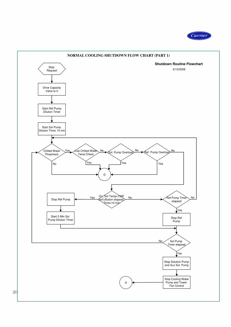
NORMAL COOLING SHUTDOWN FLOW CHART (PART 1)
Stop Request
Sol. Pump OverloadLow Chilled Water
Temp CheckChilled Water
Flowcheck
Drive Capacity
Valve to 0
Start Sol Pump Dilution Timer 15 min
Start Ref PumpDilution Timer
Ref Pump Overload
D
Yes
Yes Yes Yes
No No No
No
No
Shutdown Routine Flowchart
6/13/2008
Stop Cooling Water
Pump and Tower
Fan Control
Stop Solution Pumpand Aux Sol. Pump
Stop Ref
Pump
Start 5 Min Sol
Pump Dilution Timer
Stop Ref Pump
A
Sol Pump Timer elapsed
Ref Pump Timer
elapsed
G1_Sol Temp<158Fand dilution elapsed
Time<10 min
Yes
Yes
No
No
Yes
21
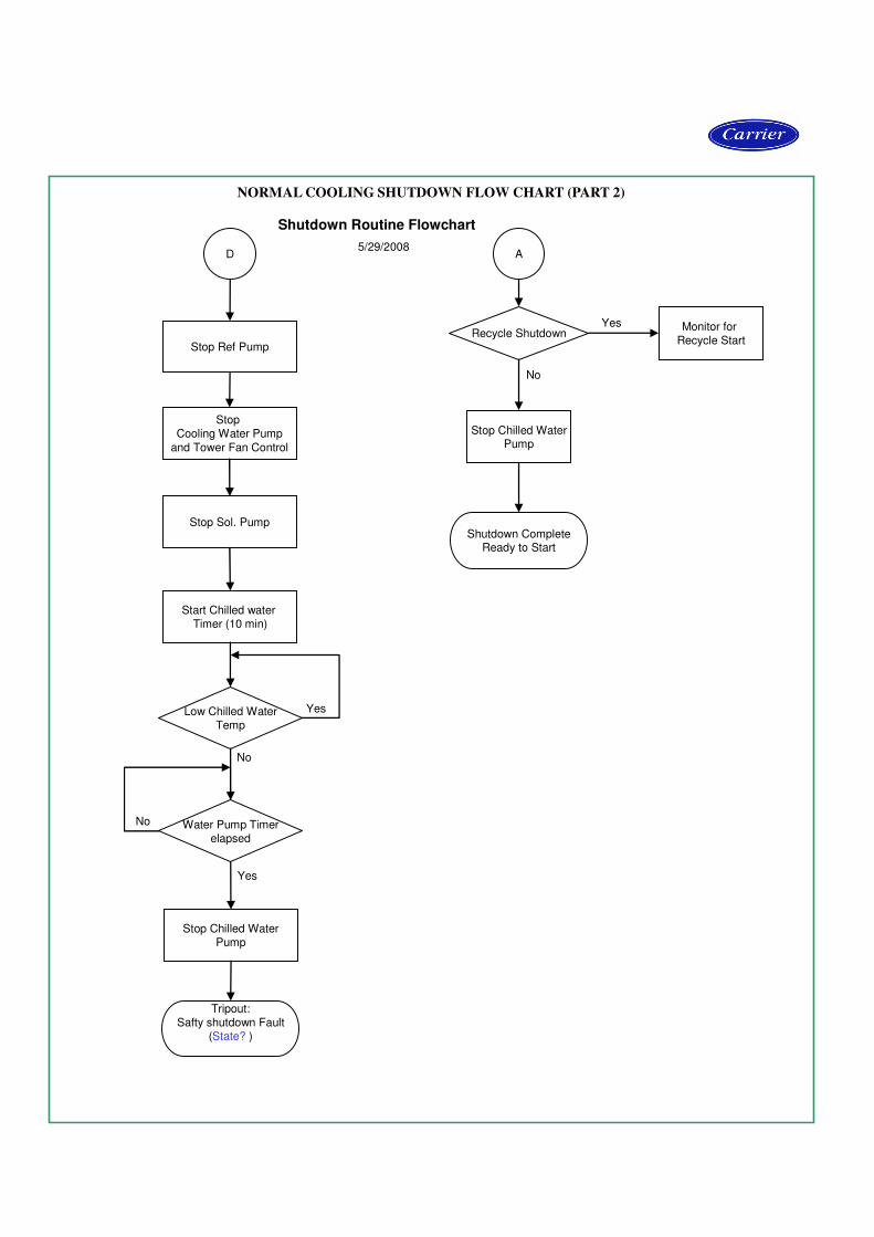
NORMAL COOLING SHUTDOWN FLOW CHART (PART 2)
D
Stop Cooling Water Pump
and Tower Fan Control
Stop Sol. Pump
Start Chilled water Timer (10 min)
Stop Chilled WaterPump
Stop Chilled WaterPump
Monitor for Recycle Start
Stop Ref Pump
Water Pump Timerelapsed
Low Chilled WaterTemp
Recycle Shutdown
Tripout:Safty shutdown Fault
(State? )
Shutdown CompleteReady to Start
A
Yes
Yes
Yes
No
No
No
Shutdown Routine Flowchart
5/29/2008

22
Hermetic Absorption Liquid Chiller Size Range: 150 to 165 tons (527 to 5802 kW)
Carrier Model Numbers: 16DEH
Part 1 – General 1.01 SYSTEM DESCRIPTION
Microprocessor controlled, double-effect absorption
liquid chiller utilizing hermetic refrigerant and solution
/auxiliary pumps, lithium bromide solution as the
absorbent, and water as the refrigerant. High pressure
steam shall be supplied to the high-temperature generator
as the heat source.
1.02 QUALITY ASSURANCE A. Chiller performance shall be rated in accordance with
ARI Standard 560 (latest edition).
B. Chiller shall be manufactured in accordance with GB/T
18431-2001,which is Chinese Industrial Standard as
applicable.
C. Chiller shall be designed and constructed to meet
applicable (GB) requirements .
D. Each chiller shall undergo a series of standard factory tests
to ensure that the unit is leak tight, that all electrical
components operate as intended, and that every aspect of
the unit fabrication meets stringent quality standards in
accordance with good practice and the manufacturer’s
quality assurance requirements.
1. The shellside of each chiller shall be leak tested by
pressurizing to 11 psig (76 kPa) with nitrogen and then
checked by spraying a soap/water mixture on all welds,
tube joints, and/or gasketed joints to identify any major
leaks. Afterward, a mass spectrometer test shall be
performed by evacuating the unit to .0001mmHg
absolute, covering the machine with a vinyl tent, and
introducing helium gas under the tent. Any remaining
leaks will allow the helium to be drawn into the
shellside of the machine. The acceptable leak rate as
measured by the mass spectrometer test shall not
exceed .00001 cc/sec standard air.
2. The tubeside of the evaporator, absorber, and con-
denser shall be hydrostatically tested at 1.25 times
rated design pressure and held for ten minutes.
3. The refrigerant and solution/auxiliary pump/motors
shall undergo standard factory tests to ensure proper
head flow, and motor output characteristics.
4. All machine wiring shall undergo an insulation
resistance test. The chiller/heater control center and all
electrical components shall also be functionally tested
to verify continuity and proper electrical operation.
5. Final assembly inspection shall consist of verifying
that all valves, controls, instrumentation, pumps, purge
components, and all other machine components have
been properly installed on the machine.
6. Each unit shall then be checked for overall appearance
and dimensional accuracy.
7. Final inspection shall be performed on each unit to
check that painting of the unit is as specified,
nameplate data is correct, and that all accessories are
8. furnished as required.
1.03 DELIVERY, STORAGE, AND HANDLING A. Unit shall be stored and handled in accordance with
the manufacturer’s recommendations.
B. Normally unit shall be charged with lithium bromide
solution at field in accordance with the manufacture
written instruction. But if customer requires, unite can
be factory charged with lithium bromide solution and
performance tested before shipping as special
requirement.
C. 1-piece shipped machines shall be shipped under
vacuum on the shell side and multiple piece shipped
machines shall be pressurize with nitrogen to 5psig
(34kPa).
D. .Chiller shall be shipped with nameplates indicating
name of manufacturer, model size, serial number, and
all other pertinent machine data.
1.04 WARRANTY Carrier shall guarantee the chiller against defects in
materials or workmanship for a period of one year from
date of initial operation or 18 months from date of
shipment, whichever occurs first. Carrier shall provide
the labor to repair or replace any part found to be
defective in material or workmanship within the
warranty period.
Part 2 – Products
2.01 EQUIPMENT A. General:
Absorption liquid chiller shall include evaporator,
absorber, condenser, high and low-temperature gen
erators, solution heat exchanger, condensate drain
heat exchanger, float trap, purging system, piping
wiring, refrigerant/solution pumps, controls, and
auxiliaries. Shipment of the machine shall be in
1 piece. Initial charge of lithium can be included
with the chiller for charging at the jobsite.
B. Operating Characteristics:
1. Chiller operation shall be characteristic of a double-
effect absorption cycle with series solution flow.
The weak solution from the absorber shall be
entering the high-temperature generator via the low
and high-temperature solution heat exchangers. A
variable frequency drive pump shall automatically
regulate the flow of solution to the high-temperature
generator to maintain optimum flow at all operating
conditions. This shall result in improved part-load
efficiency and eliminate the need for manual set-up
adjustments of the solution flow.
2. Unit shall be capable of continuous operation from
100 to 25% capacity, with entering cooling water
temperatures as low as 59 F (15 C), without the
need for a cooling tower bypass valve. Thermostat
ON/OFF control of the cooling tower fan is
recommended when cooling water temperature falls
below 59 F (15 C).
Guide specifications
23
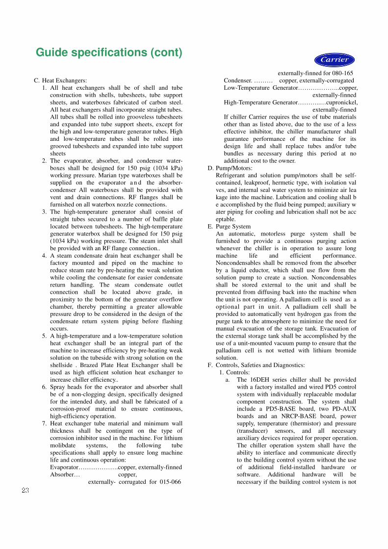
C. Heat Exchangers:
1. All heat exchangers shall be of shell and tube
construction with shells, tubesheets, tube support
sheets, and waterboxes fabricated of carbon steel.
All heat exchangers shall incorporate straight tubes.
All tubes shall be rolled into grooveless tubesheets
and expanded into tube support sheets, except for
the high and low-temperature generator tubes. High
and low-temperature tubes shall be rolled into
grooved tubesheets and expanded into tube support
sheets
2. The evaporator, absorber, and condenser water-
boxes shall be designed for 150 psig (1034 kPa)
working pressure. Marian type waterboxes shall be
supplied on the evaporator a n d the absorber-
condenser All waterboxes shall be provided with
vent and drain connections. RF flanges shall be
furnished on all waterbox nozzle connections.
3. The high-temperature generator shall consist of
straight tubes secured to a number of baffle plate
located between tubesheets. The high-temperature
generator waterbox shall be designed for 150 psig
(1034 kPa) working pressure. The steam inlet shall
be provided with an RF flange connection..
4. A steam condensate drain heat exchanger shall be
factory mounted and piped on the machine to
reduce steam rate by pre-heating the weak solution
while cooling the condensate for easier condensate
return handling. The steam condensate outlet
connection shall be located above grade, in
proximity to the bottom of the generator overflow
chamber, thereby permitting a greater allowable
pressure drop to be considered in the design of the
condensate return system piping before flashing
occurs.
5. A high-temperature and a low-temperature solution
heat exchanger shall be an integral part of the
machine to increase efficiency by pre-heating weak
solution on the tubeside with strong solution on the
shellside . Brazed Plate Heat Exchanger shall be
used as high efficient solution heat exchanger to
increase chiller efficiency..
6. Spray heads for the evaporator and absorber shall
be of a non-clogging design, specifically designed
for the intended duty, and shall be fabricated of a
corrosion-proof material to ensure continuous,
high-efficiency operation.
7. Heat exchanger tube material and minimum wall
thickness shall be contingent on the type of
corrosion inhibitor used in the machine. For lithium
molibdate systems, the following tube
specifications shall apply to ensure long machine
life and continuous operation:
Evaporator……………….copper, externally-finned
Absorber… copper,
externally- corrugated for 015-066
externally-finned for 080-165
Condenser. ……… copper, externally-corrugated
Low-Temperature Generator………………..copper,
externally-finned
High-Temperature Generator………..…cupronickel,
externally-finned
If chiller Carrier requires the use of tube materials
other than as listed above, due to the use of a less
effective inhibitor, the chiller manufacturer shall
guarantee performance of the machine for its
design life and shall replace tubes and/or tube
bundles as necessary during this period at no
additional cost to the owner.
D. Pump/Motors:
Refrigerant and solution pump/motors shall be self-
contained, leakproof, hermetic type, with isolation val
ves, and internal seal water system to minimize air lea
kage into the machine. Lubrication and cooling shall b
e accomplished by the fluid being pumped; auxiliary w
ater piping for cooling and lubrication shall not be acc
eptable.
E. Purge System
An automatic, motorless purge system shall be
furnished to provide a continuous purging action
whenever the chiller is in operation to assure long
machine life and efficient performance.
Noncondensables shall be removed from the absorber
by a liquid eductor, which shall use flow from the
solution pump to create a suction. Noncondensables
shall be stored external to the unit and shall be
prevented from diffusing back into the machine when
the unit is not operating. A palladium cell is used as a optional part in unit. A palladium cell shall be
provided to automatically vent hydrogen gas from the
purge tank to the atmosphere to minimize the need for
manual evacuation of the storage tank. Evacuation of
the external storage tank shall be accomplished by the
use of a unit-mounted vacuum pump to ensure that the
palladium cell is not wetted with lithium bromide
solution.
F. Controls, Safeties and Diagnostics:
1. Controls:
a. The 16DEH series chiller shall be provided
with a factory installed and wired PD5 control
system with individually replaceable modular
component construction. The system shall
include a PD5-BASE board, two PD-AUX
boards and an NRCP-BASE board, power
supply, temperature (thermistor) and pressure
(transducer) sensors, and all necessary
auxiliary devices required for proper operation.
The chiller operation system shall have the
ability to interface and communicate directly
to the building control system without the use
of additional field-installed hardware or
software. Additional hardware will be
necessary if the building control system is not
Guide specifications (cont)
24
a Carrier Comfort Network (CCN). The user
interface is a touch screen. It is connected to
the main basic board and gives access to a full
array of control parameters.The PD5 shall be
configurable to display either English or SI
metric units.
b. The default standard display screen shall
simultaneously indicate the following
minimum information:
- date and time of day
- primary system status message
- entering chilled water temperature
- leaving chilled water temperature
- evaporator refrigerant temperature
- entering absorber water temperature
- leaving absorber water temperature
- leaving condenser water temperature
- strong solution temperature leaving high-
temperature generator
- weak solution temperature leaving
absorber
- output signal to steam control valve
- The default screen shall be displayed if
there is no manual activity at the control
console for 15 minutes
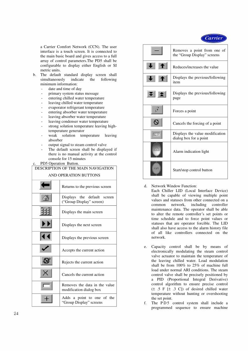
c. PD5 Operation Button.
DESCRIPTION OF THE MAIN NAVIGATION
AND OPERATION BUTTONS
Returns to the previous screen
Displays the default screen
(“Group Display” screen)
Displays the main screen
Displays the next screen
Displays the previous screen
Accepts the current action
Rejects the current action
Cancels the current action
Removes the data in the value
modification dialog box
Adds a point to one of the
“Group Display” screens
Removes a point from one of
the “Group Display” screens
Reduces/increases the value
Displays the previous/following
item
Displays the previous/following
page
Forces a point
Cancels the forcing of a point
Displays the value modification
dialog box for a point
Alarm indication light
Start/stop control button
d. Network Window Function:
Each Chiller LID (Local Interface Device)
shall be capable of viewing multiple point
values and statuses from other connected on a
common network, including controller
maintenance data. The operator shall be able
to alter the remote controller’s set points or
time schedule and to force point values or
statuses that are operator forcible. The LID
shall also have access to the alarm history file
of all like controllers connected on the
network.
e. Capacity control shall be by means of
electronically modulating the steam control
valve actuator to maintain the temperature of
the leaving chilled water. Load modulation
shall be from 100% to 25% of machine full
load under normal ARI conditions. The steam
control valve shall be precisely positioned by
a PID (Proportional Integral Derivative)
control algorithm to ensure precise control
(± .5 F [± .3 C]) of desired chilled water
temperature without hunting or overshooting
the set point.
f. The P D 5 control system shall include a
programmed sequence to ensure machine
25
readiness prior to machine start-up. The PD5
shall automatically activate and interlock the
chilled water pump, cooling water pump,
cooling tower fan upon chiller activation.
g. Upon request to start the chiller, the control
system shall start the chilled water pump and
verify chilled water flow. The controller shall
then compare the entering or leaving chilled
water temperature with the chilled water set
point. If the chilled water temperature is less
than the chilled water set point, the control
system shall enter the recycle mode until a
cooling load has been established. Once a
cooling load has been established the control
system shall start the cooling water pump and
verify flow, before starting tower fan, solution
pump and refrigerant pump. Once the
refrigerant pump is started the control system
shall then initiate a programmed warm-up
cycle. Once the full 20 minutes of warm-up
cycle is completed, the ramp loading routine
shall be initiated.
h. The control system shall automatically sense
impending abnormalities in the absorption
operating cycle and take one or all of the
following actions to either self-correct and/or
limit the machine from approaching cycle
crystallization line :
- inhibit steam control valve position until
concentration drops below preset
threshold. Message will be displayed :
“run capacity limited, high
concentration.”
- drive steam control valve to closed
position until concentration drops below
preset threshold
- initiate non-recycle shutdown of the
chiller if safety shutdown threshold
exceeded. Message will be displayed:
“dilution cycle shutdown, complete in *.*
min.”
i. A user-configurable ramp loading rate,
effective during the chilled water temperature
pulldown period, shall control the rate of
steam control valve opening to limit start-up
steam demand. The controls shall allow
configuration of the ramp loading rate in
degrees per minute of chilled water
temperature pulldown. During the ramp
loading period, a message shall be displayed
informing the operator that the chiller is
operating in ramp loading mode.
j. The control system shall automatically cycle
the machine to minimize energy usage
whenever the leaving chilled water
temperature is 3 F (1.7 C) below the desired
chilled water set point. The chilled water
pump shall remain on, and when the leaving
chilled water temperature rises above the set
point by a user-configured amount, the chiller
shall automatically restart. During the
shutdown period, a message shall be displayed
informing the operator a recycle is pending.
k. The control center shall allow reset of the
chilled water temperature set point based on
any one of the following criteria:
- Chilled water reset based on a remote
temperature (such as outdoor air).
- Chilled water reset based on water
temperature rise across the evaporator.
When reset is active, a message shall be
displayed indicating the type of reset in effect.
l. The control center shall limit the opening of
the steam control valve to 65% (user-
configurable) open at startup until the warm-
up period has been completed and ramp
loading is enabled.
m. When the stop button is pressed, or remote
contacts open the control center shall
immediately drive the steam control valve to
the closed position and initiate the normal
shutdown sequence including dilution cycle.
The display shall indicate : “dilution cycle
shutdown”
2. Safeties:
a. Unit shall automatically shutdown when any of
the following conditions occur: (Each of these
protective limits shall require manual reset and
cause an alarm message to be displayed on the
screen, informing the operator of the shutdown
cause.)
- solution pump VFD overload/high
temperature
- refrigerant pump motor overload/high
temperature
- low chilled water temperature
- low evaporator refrigerant temperature
- high-temperature generator high solution
temperature
- high-temperature generator high pressure
- high-temperature generator high solution
level
- high-temperature generator low solution
level
- loss of evaporator water flow
- loss of cooling water flow
b. The control system shall detect conditions which
approach protective limits and take self-
corrective action prior to an alarm occurring. The
system shall automatically reduce chiller
capacity when any of following parameters are
outside their normal operating range:
26
- low evaporator refrigerant temperature
- high-temperature generator high
saturation temperature
- high-temperature generator high solution
temperature
- high solution concentration
During the capacity override period, a pre-alarm
(alert) message shall be displayed informing the
operator which condition is causing the capacity
override. Once the condition is again within
acceptable limits, the override condition shall
terminate and the chiller shall revert to normal
chilled water control. If during either condition
the protective limit is reached, the chiller shall
shutdown, an alarm shall be generated, and a text
message shall be displayed informing the
operator which condition caused the shutdown
and alarm.
3. Diagnostics and Service:
a. The control system shall execute a series of pre-
start checks whenever a start command is
received to determine if pressures, temperatures,
and timers are within prestart limits, thereby
allowing start-up to proceed. If any of the limits
are exceeded a text alert message will be
displayed informing the operator of the cause of
the pre-start alert.
b. The control system shall provide a manual test
which permits selection and test of individual
control components and inputs. The screen will
show the actual reading of each transducer and
each thermistor installed on the chiller.
The test shall automatically energize the
refrigerant pump, solution pump, tower fan relay,
alarm relay, chilled water and cooling water
pumps and chiller run relay, and the control
system shall confirm water flows have been
established and require operator confirmation
prior to proceeding to the next test.
A capacity valve actuator test shall allow the
operator to test the steam control valve position
by manually increasing, decreasing or holding in
response to the key pressed. Upon completion of
the steam control valve test the control valve
shall revert to the closed position.
A variable frequency drive test shall allow the
operator to check the VFD speed value by
manually increasing, decreasing or holding in
response to the key pressed. Upon completion of
the VFD test the VFD speed shall revert to 0.0%.
c. All sensors shall have quick disconnects to allow
replacement of the sensor without replacement of
the entire sensor wire.
4. Building Control System Interface:
The chiller control system shall have the ability to
interface and communicate directly to the building
control system without the use of additional field
installed hardware and software. The building control
system and the absorption chiller must be supplied by
the same manufacturer. If different building control
and chiller suppliers are chosen the chiller shall be
supplied with a dataport module which shall translate
the information in the chiller microprocessor to an
ASCII steam of data which can be read by any
manufacturer’s building management control system.
G. Electrical Requirements:
1. Power supply to the unit shall be 3-ph, 50Hz,
380V.. If need , Carrier also can meet owner’s
requirement .
2. Contractor shall supply and install the electrical
power line and all auxiliary electrical protection
devices per local code requirements and as
indicated necessary by the chiller manufacturer.
3. Contractor shall supply and install electrical wiring
and devices required to interface the chiller
controls with the building control system, if
applicable.
H. Piping Requirements:
1. Piping and instrumentation for the chilled water,
cooling water, steam, and condensate piping shall
be supplied and installed by the contractor/owner.
2. Chilled water flow switch shall be factory supplied
and factory installed in the evaporator water nozzle.
Cooling water flow switch shall be field installed or
factory installed if customer requires and supplied
by either the chiller manufacturer or the
contractor/owner.
3. Piping from the rupture disk shall be provided and
installed by the contractor/owner and piped in
accordance with the chiller manufacturer’s written
instructions.
I. Thermal Insulation:
Insulation of cold or hot surfaces shall be field
supplied and field installed on the machine. Chiller
manufacturer shall specify the recommended material
and surface area to be insulated.
J. Sound Level:
The overall sound pressure level of the chiller shall not
exceed 80 dbA when measured at standard of JB/T
4330
K. Start-up:
1. C a r r i e r shall provide a factory-trained service
representative, employed by the chiller
manufacturer, to perform and/or supervise chiller
pressure test (when required), charge chiller with
refrigerant (water) and lithium bromide solution,
place unit into operation, and calibrate all controls
in accordance with the manufacturer’s written start-
up, operating, and maintenance instructions.
2. After unit start-up has been performed, the same
Carrier representative shall be available for a period
of instruction (not to exceed 4 hours) to instruct the
Guide specifications (cont)
27
owner’s personnel in the proper start-up, operation,
and maintenance procedures.
3. Carrier shall provide the following literature:
a. Installation, Operation and Maintenance
Instructions
b. Field Wiring Diagrams
L. Options and Accessories:
1. High-Pressure Waterboxes:
Waterboxes rated for 250 psig (1724 kPa) or 300
psig (2068 kPa) working pressure shall be furnished
when specified on the equipment schedule
2. Special Tubing:
Tubing of non-standard materials and/or wall
thickness shall be provided when specified on the
equipment schedule.
3. Shipping Configuration:
Chiller shall ship in either 1 or 2 pieces, as specified
on the equipment schedule.
4. Cooling Water Flow Switch:
A cooling water flow switch, rated for either
150 psig (1034 kPa), 250 psig (1724kPa), or 300
psig (2068 kPa) shall be field installed or factory
installed if customer requires and supplied by either
the chiller manufacturer or the contractor/owner.
5. Steam Valve (electric or pneumatic)
A steam valve shall be provided when specified on
the equipment schedule.
6. Unit Voltage
Unit shall be capable of operating on 3 phase, 50 Hz,
when specified on equipment schedule.
7. Isolation Package:
A vibration isolation package consisting of machine
soleplates and neoprene isolation pads shall be
furnished for field installation when specified on the
equipment schedule.
8. Palladium Cell:
Palladium cell is provided to automatically vent
hydrogen gas from the purge tank to the atmosphere
when specified on the equipment schedule.