Embed Size (px)
Citation preview

SAVE THESE INSTRUCTIONS
163cc Power Trowel
Owner’s Manual
WARNING: Read and understand all instructions, warnings, and cautions before using this
product. Failure to follow the instructions, warnings, and cautions may result in serious personal
injury and/or property damage.
Item #49391

Page 2 of 33
Thank you very much for choosing a North Star product!
For future reference, please complete the owner’s record below:
Serial Number/Lot Date Code: ________________________________
Purchase Date: ____________________________________________
Save the receipt, warranty, and this manual.
This Power Trowel is designed for certain applications only. Northern
Tool and Equipment cannot be responsible for issues arising from
modification or use of this product in an application for which it was not
designed. We strongly recommend that this product not be modified
and/or used for any application other than that for which it was designed.
For technical questions, please call 1-800-222-5381.

Page 3 of 33
Table of Contents
Intended Use .......................................................................................................................................... 4
Technical Specifications ...................................................................................................................... 4
Important Safety Information ............................................................................................................... 5
Specific Operation Warnings ............................................................................................................... 8
Main Parts of Power Trowel ............................................................................................................... 10
Assembly Instructions ........................................................................................................................ 11
Before Each Use .................................................................................................................................. 14
Operating Instructions ........................................................................................................................ 15
Start the Engine .............................................................................................................................. 15
Operation ........................................................................................................................................ 15
Stop the Engine .............................................................................................................................. 15
After Each Use ..................................................................................................................................... 16
Maintenance ........................................................................................................................................ 17
Change V-Belt ................................................................................................................................ 18
Change BLADES SET .................................................................................................................... 19
Parts Diagram ...................................................................................................................................... 22
Handle ............................................................................................................................................ 22
Blade ............................................................................................................................................... 24
Gear Box ......................................................................................................................................... 26
Safety Ring ..................................................................................................................................... 28
Troubleshooting .............................................................................................................................. 30
Replacement Parts .............................................................................................................................. 31
Limited Warranty ................................................................................................................................. 32

Page 4 of 33
Intended Use
This gas-powered trowel with 5.5 HP 160cc Honda GX-160 engine is great for use on big jobs like
parking lots, driveways, concrete patios and more. A safety stopper located on handle grip allows for
easy emergency shutdown.
Technical Specifications
Weight 209.4 lb. (95 Kgf)
Operating Size 39 x 67 x 39 (in) (1000 x 1700 x 1000 (mm))
Working Blade Diameter 36 (in) (914 mm)
Number of Blades 4
Pitch Range 0 – 15°
Trowel Speed 60 – 130 rpm
Efficiency 2152(ft²/h)
Engine Honda GX-160 / 163cc

Page 5 of 33
Important Safety Information
The warnings, cautions, and instructions in this manual cannot cover all possible conditions or
situations that could occur. Exercise common sense and caution when using this tool. Always be
aware of the environment and ensure that the tool is used in a safe and responsible manner.
DO NOT allow persons to assemble or operate this product until they have read this manual and
have developed a thorough understanding of how the product works.
Use the right tool for the job. DO NOT attempt to force small equipment to do the work of larger
industrial equipment. There are certain applications for which this equipment was designed. It will
do the job better and more safely at the capacity for which it was intended. DO NOT use this
equipment for a purpose for which it was not intended.
Industrial or commercial applications must follow OSHA requirements.
Some dust created by power sanding, sawing, grinding, drilling, and other construction activities
contains chemicals known to the State of California to cause cancer, birth defects, or other
reproductive harm. Some examples of these chemicals are:
- lead from lead-based paints,
- crystalline silica from bricks and cement and other masonry products
- arsenic and chromium from chemically-treated lumber.
Your risk from these exposures varies, depending on how often you do this type of work. To
reduce your exposure to these chemicals: work in a well-ventilated area, and work with approved
safety equipment, such as dust masks that are specially designed to filter out microscopic
particles.
Handling the power cord on corded products may expose you to lead, a chemical known to the
State of California to cause cancer and birth defects or other reproductive harm. Wash hands
after handling.
WORK AREA SAFETY
Inspect the work area before each use. Keep the work area clean, dry, free of clutter, and well lit.
Cluttered, wet, or dark work areas can result in injury.
Do not use the Power Trowel where there is a risk of causing a fire or an explosion; e.g., in the
presence of flammable liquids, gases, or dust.
Keep children and bystanders away from the work area while operating the Power Trowel. Do not
allow children to handle the Power Trowel.
Be aware of all power lines, electrical circuits, water pipes, and other mechanical hazards in your
work area. Some of these hazards may be hidden from your view and may cause personal injury
and/or property damage if contacted.

Page 6 of 33
PERSONAL SAFETY
Stay alert, watch what you are doing, and use common sense when operating the Power Trowel.
Do not use the Power Trowel while you are tired or under the influence of drugs, alcohol, or
medication.
Dress properly. Do not wear loose clothing, dangling objects, or jewelry. Keep your hair, clothing
and gloves away from moving parts. Loose clothes, jewelry, or long hair can be caught in moving
parts.
Use ANSI Z87.1-approved safety goggles or safety glasses with side shields, or when needed, a
face shield. Use a dust mask in dusty work conditions. Also use non-skid safety shoes, hardhat,
gloves, dust collection systems, and hearing protection when appropriate. This applies to all
persons in the work area.
Do not overreach. Keep proper footing and balance at all times.
Remove adjusting keys or wrenches before starting the Power Trowel. A wrench or key that is left
attached to a rotating part of the Power Trowel may cause personal injury.
No smoking, matches, or open flames around machine. Fuel is flammable.
Do not touch hot surfaces.
Persons not operating should be at least 10 feet away while equipment is in use.
Engine exhaust contains carbon monoxide. This is a poison you cannot see or smell. NEVER use
in doors.
Do not operate without guards in place.

Page 7 of 33
POWER TROWEL USE AND CARE
Do not force the Power Trowel to perform an operation other than its intended use. Power
Trowels do a better and safer job when used in the manner for which they are designed. Plan
your work, and use the correct Power Trowel for the job.
Check for damaged parts before each use. Carefully check that the Power Trowel will operate
properly and perform its intended function. Replace damaged or worn parts immediately. Never
operate the Power Trowel with a damaged part.
Store the Power Trowel when it is not in use. Store it in a dry, secure place out of the reach of
children. Inspect the Power Trowel for good working condition prior to storage and before re-use.
Use only accessories that are recommended by the manufacturer for use with the Power Trowel.
Accessories that may be suitable for one Power Trowel may create a risk of injury when used with
another Power Trowel.
Keep guards in place and in working order. Never operate the product without the guards in
place.
Keep the Power Trowel blade clean.
Do not leave the Power Trowel running unattended.
Shut off the fuel valve when the engine is not in use.
Only use the recommended fuel to avoid damaging the equipment.
Oil does not come with the machine. Add oil to engine before the first use.
Check oil levels before operating the machine.
DO NOT refuel the engine while it is still hot. Fuel is flammable.
DO NOT service engine while it is still hot.

Page 8 of 33
Specific Operation Warnings
To avoid fatal accident
Stop the engine before refueling and be careful not to spill fuel during the refueling. Spilled fuel may ignite causing a fire.
Do not refuel the engine near flammable objects to avoid fire.
Do not run the engine in enclosed areas to prevent carbon monoxide poisoning.
To protect the operator
When fatigue from operation, the operator must stop the machine and take break.
Hearing protection is required as this machine creates a noise emission while 1 m (3 feet) away from the equipment.
To avoid injury or damage
The power trowel is only operated by authorized persons who:
are at least 18 years of age.
are physically and mentally able to operate the power trowel.
are properly trained in the operation and the maintenance of the power trowel by the owner or its authorized representative.
are assessed to be able to carry out their duties reliably.
People who are drinking alcohol beverages and/or taking drugs are not allowed to operate the power trowel.
People are not allowed to enter into the danger zone of the power trowel.
The operator has to monitor the danger zone all the time. It is not allowed to operate if there is a person in the danger zone.
The operator has to give warning signs in case of an emergency situation.
The power trowel can only be operated when the adequate stability is granted.
The operator has to control the running speed of the power trowel all the time during its operation so that the machine can be stopped at any time.
The operator must turn off the power trowel completely as described in this manual before leaving the operating position. Also, the power trowel must be secured against unauthorized use.
The engine has to be turned off and secured against re-starting by pulling out the sparking plug socket during the maintenance and servicing.
The operator has to control the power trowel as regards functions and obvious defects before use.
Discovered defects must be reported to supervising personnel and to the operator. Do not leave the defects which may cause serious injury of the operator.
Do not operate the power trowel when a defect endangers the safety of the operator until the defect is rectified.
The power trowel has to be checked by an expert in regular bases (at least once a year). And it must be checked by an expert before the initial use and after the essential modification.
The power trowel generates mechanical heat so do not touch the body of engine, muffler or other parts during the operation, which may cause heat burn. Please wait until it cools down to touch.
The operator must be fully equipped with safety equipment including a crash helmet, safety

Page 9 of 33
gloves, safety shoes, safety glasses and mask before operating the power trowel.
Do not insert your hand or finger between pulley cover and engine during the operation, it may break your hand or finger.
Do not transport the power trowel by motor vehicle with fuel in the trowel’s fuel tank.
Do not lift the power trowel by a person when putting on and off from vehicle. Always use a proper lifting crane to move. Lifting by person may cause personal injury due to its heavy weight.
Make sure to securely fasten the power trowel for transportation. Improper fastening as holding the handle of the power trowel during the transportation may cause an injury.
Note: Also refer to the enclosed engine manual if there is a problem or a question on engine.

Page 10 of 33
Main Parts of Power Trowel
01 Throttle Lever
02 Blade Pitch Handle
03 Engine Stop Switch
04 Handle
05 Belt Cover
06 Blade Holder
07 Blade
08 Safety Ring
09 Engine Stop Switch
10 Engine Fuel Cap
11 Engine Air Filter
12 Engine Muffler

Page 11 of 33
Assembly Instructions
Note: To allow clearance to adjust the blade pitch in step 5, support the safety ring of the screed on some bricks between the blade tips so the blade pitch can be changed during testing of this feature.
1. Attach the handle to the screed using 4 bolts, Plain
Washers, Spring Washers, and Nuts (see the Handle
parts diagram; items 25, 26, 27, & 30). Be sure to
check the direction of the handle before attaching it.
2. Tighten the Nuts with the 17mm wrench. Torque should be 60
ft-lbs. (830 kgf.cm).
①
Page 12 of 33
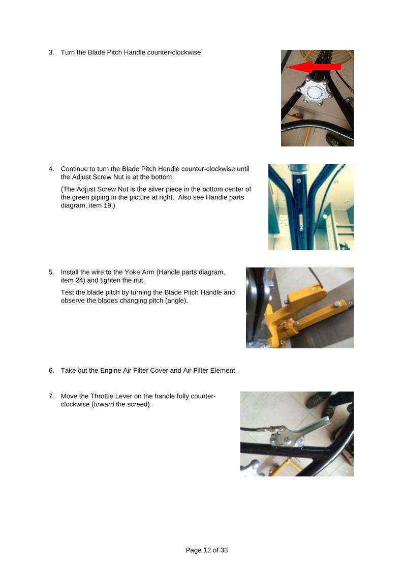
3. Turn the Blade Pitch Handle counter-clockwise.
4. Continue to turn the Blade Pitch Handle counter-clockwise until
the Adjust Screw Nut is at the bottom.
(The Adjust Screw Nut is the silver piece in the bottom center of
the green piping in the picture at right. Also see Handle parts
diagram, item 19.)
5. Install the wire to the Yoke Arm (Handle parts diagram,
item 24) and tighten the nut.
Test the blade pitch by turning the Blade Pitch Handle and
observe the blades changing pitch (angle).
6. Take out the Engine Air Filter Cover and Air Filter Element.
7. Move the Throttle Lever on the handle fully counter-
clockwise (toward the screed).

Page 13 of 33
8. Check that the engine throttle lever (silver
lever in picture) is at its idle position (fully left
in picture) then attach the Accelerator Cable
position (3) and wire (4).
9. Assemble the Air Filter Element and the Air Filter Cover.
10. Unplug the wiring connector of the Engine Stop Switch (on the red section of the engine housing).
11. Plug the supplied connector of the Engine Stop
Switch into the engine connector (not the switch
connector) from the above step.
12. Remove a bolt from the engine housing, put the ring
terminal of the Engine Stop Switch over the bolt,
replace the bolt and retighten it.
13. Gather the cables and tie them with a cable tie.
③
④
Page 14 of 33
Before Each Use
Engine
Recommended Fuel
The trowel engine requires fresh, clean, regular, unleaded gasoline. Fuel containing water or dir
t will damage the fuel system. Consult to engine owner’s manual for complete fuel specifications.
DANGER: Adding fuel to the tank should be done only when the engine is stopped and has had
an opportunity to cool down to avoid a risk of an explosion or fire from a fuel spill. In the event of
a fuel spill, DO NOT attempt to start the engine until the fuel residue has been completely wiped
up, and the area surrounding the engine is dry.
Before starting
Read and understand the safety and operating instruction manual of the engine.
Check:
- Oil level in engine; refill if necessary.
- Fuel level; refill the tank if necessary.
- Condition of fuel lines.
- Condition of air filter.
- The spark plug
Trowel
Check all the bolts, nuts and belts and tighten any if necessary.
Check the belt tension.
Check the condition of the blades. Repair or replace any blades that are damaged or bent.
Check the general condition of the trowel and its components and clean any foreign material (dirt,
fragments, etc.) from the trowel that may be thrown off and cause injury.

Page 15 of 33
Operating Instructions
Operators must be trained in the use of the power trowel and maintain practiced skill. It is dangerous to operate this machine improperly or by an untrained person. An operator should read and understand the manual and follow its directions. This power trowel is equipped with an engine stop switch. Test the switch each time the engine is started. NEVER disable or disconnect the switch. It is provided for operator safety. Injury may result if it is disabled, disconnected, or improperly maintained.
In an emergency situation, stop the engine immediately with the engine stop switch. In normal conditions, do not stop the engine when the power trowel is at high speed or the engine temperature will rise suddenly, possibly causing engine parts to jam or the oil to deteriorate.
Start the Engine
1. Open the fuel valve on the engine.
2. Close the choke lever on the engine. A warm engine may not need to be choked.
3. Close the engine stop switch (set it to ON).
4. Pull the starter rope to start the engine.
5. Open the choke and allow the engine to warm up at slow speed for 5 minutes.
6. Test the engine stop switch. If it is working properly, the engine will stop.
7. Perform steps 3 and 4 again to restart the engine to use the power trowel.
Operation
1. While firmly grasping the power trowel handle and with the engine stop switch closed, pull the throttle lever back toward the operator to increase the speed of the engine and start the blades turning.
2. Use the handle to move the power trowel: to move left, apply a slight upward pressure on the handle, to move right, press down slightly; to move forward, twist handle clockwise; to move backward, twist handle counterclockwise; to rotate in one spot, hold handle in a neutral position
3. A good practice to finish concrete is move the trowel from side to side while moving backward.
Stop the Engine
1. If the engine has been running for a while and is hot, push the throttle lever fully toward the trowel to minimize the engine speed then let the engine idle for a few minutes.
2. Release the engine stop switch to stop the engine.
3. Close the fuel valve. See engine the instruction manual for further information.

Page 16 of 33
After Each Use
Cleanup
Check that the compactor engine is turned off and cooled before attempting any maintenance,
cleaning, or inspection. Performing maintenance on an operating compactor can cause injury.
1. Wash the trowel with water immediately after use so concrete does not dry on the machine, taking
care to not get the engine or electrical controls wet.
2. Clean the engine cylinder cooling fins. A broom or old brush are good tools to remove concrete
before it becomes solid.
3. Apply a thin coat of diesel fuel to the blades and blade arms to prevent rust.
Refer to the engine manufacturer’s instruction manual for additional information about engine maintenance.
Storage
If storing the trowel for an extended period of time (more than 30 days) or transporting it:
1. Clean the trowel as described above
2. Remove the blades.
3. Drain the fuel tank and run the engine briefly until the fuel in the carburetor is completely
consumed.
4. Clean or replace the air filter.
5. Change the engine oil. Follow the procedures described in the engine manual for engine storage.
6. Store the trowel and blades separately in a clean, dry area
7. Cover the trowel and blades completely with a cloth or tarp.
If transporting the power trowel, lift it using a proper lifting crane when moving it on and off a truck. Lifting the trowel by hand may cause personal injury due to its heavy weight.

Page 17 of 33
Maintenance
Check that the compactor engine is turned off and cooled before attempting any maintenance,
cleaning, or inspection. Performing maintenance on an operating compactor can cause injury.
Maintain the Power Trowel by adopting a program of conscientious repair and maintenance in
accordance with the following recommended procedures. Also refer to the engine manufacturer’s
instruction manual for additional information about engine maintenance. The following chart is based
on a normal operation schedule.
Maintenance Interval Maintenance Point
Daily before operating
Check and tighten the external hardware
Check and adjust the belt tension
Check the fuel level
Check the engine oil level (see the engine manual)
Inspect the fuel lines
Inspect the air filter and replace it if needed
Check the spark plug
After the first 20 operating hours Check and adjust the belt tension
Change the engine oil (see the engine manual)
After the first 50 operating hours or every week
Check and adjust the belt tension
Clean the air filter and replace if needed
Change the engine oil (see the engine manual)
Check and clean the spark plug
After the first 100 operating hours or every month
Clean the fuel strainer
Change the engine oil (see the engine manual)
After the first 300 operating hours or every year
Change the grease in gear operating parts
Check and adjust the valve clearance
Clean the cylinder head
Change the engine oil (see the engine manual)

Page 18 of 33
Change V-Belt
Check that the power trowel engine is turned off and cool before attempting to change the V-belt.
Changing the V-belt while the trowel is still hot or operating will cause injury.
1. Remove the bolts to remove the belt cover. The pictures below show the front and rear brackets
that hold the black belt cover to the engine.
2. Remove the belt
3. Prepare a new belt (item 9 in the belt cover parts list).
4. When fitting each belt, fit to the smaller pulley first, then fit the bigger pulley.
5. Reinstall the belt cover.

Page 19 of 33
Change BLADES SET
Check that the power trowel engine is turned off and cool before attempting to change the V-belt.
Changing the V-belt while the trowel is still hot or operating will cause injury.
Supplies: Blade Set, Bolt for Blade Set, Plain Washer for bolt, Spring Washer for Bolt,
1/2” Spanner(or 13mm), Torque Wrench for 1/2(Including Socket)
Check that the blade arms are not bent or damaged before replacing the blade set. Replace
the arms first if they are bent.
1. Place the power trowel on the flat floor.
2. Twist the angle controller knob to the left until the blades are parallel to the floor (Fig. 1).
3. Loosen the inner bolt with the 1/2 in. wrench (Fig. 2).

Page 20 of 33
4. Loosen the outside bolt with the 1/2 in. wrench (Fig. 3).
5. Remove the blade.
6. Clean the lower part of the blade arm of foreign debris.
7. Place the new blade under the blade arm and align the bolt holes on each.
8. Place a spring washer and plain washer on a bolt in that order. Place one bolt through
the inner bolt hole on the blade arm and screw the bolt into the blade. Tighten by hand.
Repeat for the outer bolt hole on the same blade arm.
9. Alternate tightening the inner and outer bolts twice, increasing the torque setting each
time. Do not skip a step or raise the torque too much. The blade will not be properly
balanced and this will affect the concrete finish.
9.1 Set the torque wrench to 13.02 ft-lb (17.66 N-m or 180 kgf.cm) and tighten the inner
bolt (Fig. 4).

Page 21 of 33
9.2 Keep the torque wrench setting at 13.02 ft-lb and tighten the outer bolt (Fig. 5).
9.3 Reset the torque wrench to 14.46 ft-lb (19.62 N-m or 200 kgf.cm) and tighten the outer
bolt again.
9.4 Keep the torque wrench setting at 14.46 ft-lb and tighten the inner bolt a second time.
9.5 Set the torque wrench to 17.36 ft-lb (23.54 N-m or 240 kgf.cm) and tighten the inner
bolt for the third time.
9.6 Keep the torque wrench setting at 17.36 ft-lb and tighten the outer bolt a third time.
10. Repeat for the other three blades.

Page 22 of 33
Parts Diagram
Handle

Page 23 of 33
REF Parts No. Description Q’TY Dimension
1 RG-003 Plastic Cover 2
2 QSC-M4*8 Screw 2 M4x8
3 QWS-PM4 Plate Washer 2 M4
4 TSA-01 Throttle Assy. 1
5 QNT-NM4 Nylock Nut 2 M4
6 W436F-001 Handle WA 1
7 PAS-02 Stop Switch(release bar Type) 1
8 436F-01-001 Adjust Knob 1
9 QSP-5X50 Spring Pin 1 5x50
10 QBR-51104 Bearing 1
11 QBL-M6X10 Bolt 1 M6x10
12 436F-01-004 Aluminium Guide 1
13 QWS-WM19 Wave Washer 1 M19
14 QWS-PM19 Plate Washer 1 M19
15 QSR-S18 Snap Ring 1 S18
16 436F-01-002 Adjust Screw Pipe 1
17 QBL-M6X8 Bolt 1 M6x8
18 QWS-PM6 Spring Washer 1 M6
19 436F-01-003 Screw Guide 1
20 QSP-5X30 Spring Pin 1 5x30
21 436F-01-007 WT Steel Wire 1
22 436F-02-004 Yoke Arm Pin 1
23 QSR-S10 Snap Ring 2 S10
24 436F-02-003B Yoke Arm 1
25 QNT-NM10 Nylock Nut 10 M10
26 QWS-SM10 Spring Washer 14 M10
27 QWS-PM10 Plate Washer 18 M10
28 436F-02-001 Handle Support Base 1
29 QBL-M10X70 Bolt 1 M10x70
30 QBL-M10X35 Bolt 4 M10x35
31 436F-02-002 Upper Bracket 1
32 436F-01-005 Alumium yoke 1
33 436A-01-010 Wheel 1
34 QSP-3X30 Spring Pin 1 3x30

Page 24 of 33
Blade

Page 25 of 33
REF Parts No. Description Q’TY Dimension
26 QWS-SM10 Spring Washer 5 M10
27 QWS-PM10 Plate Washer 4 M10
69 436F-02-005B Press Plate Cap 1
70 QBR-6009 Bearing 1 6009
71 436F-02-006B Press Plate Cap 1
72 QBL-M10X20 Bolt 4 M10x20
73 QBL-BBM10X35 Round Head Bolt 4 M10x35
74 QNT-TM10 Thin Nut 8 M10
75 QBL-SHM10X30 Square Head Bolt 4
76 QBL-7/16X11/2 Bolt 8 7/16*3/2L
77 QWS-SM8 Spring Washer 8 M8
78 QWS-PM8 Plate Washer 8 M8
79 436F-02-009B Blade Arm 4
80 436F-02-014 Blade Assembly 4
81 436F-02-008 Tilt Arm 4
82 QOR-S22 O-ring 4 22x1.5t
83 436F-02-007B Spider 1
84 436F-02-010 Spider Bushing 1
85 QBL-LM10X30 Socket Bolt 1 M10x30

Page 26 of 33
Gear Box

Page 27 of 33
REF Parts No. Description Q’TY Dimension
436F-03 Gear Box Assembly 1
25 QNT-NM10 Nylock Nut 4 M10
26 QWS-SM10 Spring Washer 5 M10
27 QWS-PM10 Plate Washer 5 M10
36 QBL-M6X16 Bolt 16 M6x16L
37 QRV-M8 Release Valve 1
38 436F-03-004 Big Cover 1
39 436F-03-005 Gasket of Big Cover 1
40 QBL-FHM10x25 Flat Socket Head Bolt 1 M10x25
41 QWS-SSM10 Washer 1 M10
42 QBR-30305 Bearing 1 30305
43 436F-03-008 Worm Gear 1
44 QBR-6206 Bearing 1 6206
45 QKY-W6X10X25 Wood Key 1 6x10x25
46 436F-02-012 Main Shaft 1
47 QKY-6X25 Key 1 6x25
48 436F-03-001 Shell 1
49 QBL-STM10x40 Stud Bolt 4 M10x40
50 QBL-M10X16 Bolt 1 M10x16
51 436F-03-007 Worm Shaft 1
52 QBR-32004 Bearing 1 32004
53 436F-03-006 Gasket of Side Cover 2
54 QOR-P55 O-Ring 2 55x3.5t
55 436F-03-003 Output Side Cover 1
56 QOS-20X40X8 Oil Seal 1 20x40x8t
57 436F-04-005 Pulley 1
58 QKY-5X35 Key 1 5x35
59 QBL-M8X10 Bolt 1 M8x10
60 QOS-27X47X10 Oil Seal 1 27x47x10t
61 436A-03-008WT Oil Drain 2
62 QBR-6004 Bearing 1 6004
63 436F-03-002 Side Cover 1
64 QOCW-M27x1.5 Oil Check Windows 1 M27x1.5

Page 28 of 33
Safety Ring

Page 29 of 33
REF Parts No. Description Q’TY Dimension
77 QWS-SM8 Spring Washer M8
86 GX160 Engine GX-160 1
87 W436F-005 Hook Lift 1 (Option)
88 QBL-SHM8X20 Socket Head Cap Bolt 4 (Option)
89 436F-04-013 Clutch Busing 1
90 CA-01 Clutch 1
90-1 CA-01-004 Face Plate 1
90-2 QBL-AM8x16 Set Screw 2 M8x16
90-3 CA-01-005 Clutch Spring 1
90-4 CA-01-003 Shoe Weight 1
90-5 CA-01-002 Clutch Drum 1
90-6 QBR-6006 Bearing 1 6006
90-7 CA-01-001 Clutch Shaft 1
91 QBL-M8X35 Bolt 1
92 QWS-SPM8 Special Plate Washer 1
93 QKY-5x5x50 Key 1
95 436F-04-006 Belt Cover 1
97 QBT-A26 V-Belt 1 A26
98 W436F-002 Engine Mount Plate
99 436F-04-107 Engine Mount Bushing
100 QBL-FHM8X20 Flat Head Cap Bolt 4
101 QNT-M8 Nut 8 M8
102 QBL-LM8X40 Socket Head Bolt 4 M8X40
103 QWS-PM8 Plate Washer 8 M8
104 436F-04-004 Cup 4
105 436F-04-003 Rubber 4
106 W436F-004B Safety Ring 1

Page 30 of 33
Troubleshooting
To avoid risk of severe injury, turn off the engine and allow it to cool before performing any
maintenance, cleaning, or inspection.
Check the list below before addressing the problems to servicing personnel including local dealer. If the problem continues after the following troubleshooting, call your local dealer for future assistance.
Problem Possible Cause Solution
Trowel does not develop its full
speed (poor performance)
Engine throttle control does not completely open
Open the engine throttle control completely
Throttle control does not adjusted correctly
Adjust the throttle control correctly
The cement is too wet for finishing
Dry the cement before operation
Drive belt is loosened up or warn out, slipping on pulleys
Adjust/replace the belt. or check whether the engine mounting bolts are tightened
Warm gear binding Check grease and wear of
gear. Add /change grease.
Automatic clutch/ pulley are loosened up.
Check status of contact. Add lubricant or replace the clutch
Air filter clogged with dust, reducing engine performance
Clean/replace the air filter
Engine speed is too low
Check engine speed with
tachometer. Adjust/repair
engine to run at correct
speed.
Note: Refer to engine
manual.
Engine running, but no blade
rotation
Engine throttle is not opened
Drive belt is loosened or broken. Adjust/replace it
Clutch damage Inspect / replace clutch
Engine speed is too low Check and adjust engine
speed
Too much oil in exciter Adjust the oil level in exciter
correctly
Trowel jumps or works
unevenly.
Cement surface is too hard Wet cement (if possible)
V-belt is loose or worn out Adjust/replace the V-belt

Page 31 of 33
Replacement Parts
For replacement parts and technical questions, please call Customer Service at 1-800-222-5381.
Not all product components are available for replacement. The illustrations provided are a
convenient reference to the location and position of parts in the assembly sequence.
When ordering parts, the following will be required: model number, serial number/lot date code,
and description.
The distributor reserves the rights to make design changes and/or improvements to product lines
and manuals without notice.

Page 32 of 33
Limited Warranty
Northern Tool and Equipment Company, Inc. ("We'' or '"Us'') warrants to the original purchaser only ("You'' or “Your”) that the North Star product purchased will be free from material defects in both materials and workmanship, normal wear and tear excepted, for a period of two years from date of purchase with the Honda GX engine having a period of three years from date of purchase. The foregoing warranty is valid only if the installation and use of the product is strictly in accordance with product instructions. There are no other warranties, express or implied, including the warranty of merchantability or fitness for a particular purpose. If the product does not comply with this limited warranty, Your sole and exclusive remedy is that We will, at our sole option and within a commercially reasonable time, either replace the product or product component without charge to You or refund the purchase price (less shipping). This limited warranty is not transferable. Limitations on the Warranty This limited warranty does not cover: (a) normal wear and tear; (b) damage through abuse, neglect, misuse, or as a result of any accident or in any other manner; (c) damage from misapplication, overloading, or improper installation; (d) improper maintenance and repair; and (e) product alteration in any manner by anyone other than Us, with the sole exception of alterations made pursuant to product instructions and in a workmanlike manner. Obligations of Purchaser You must retain Your product purchase receipt to verify date of purchase and that You are the original purchaser. To make a warranty claim, contact Us at 1-800-222-5381, identify the product by make and model number, and follow the claim instructions that will be provided. The product and the purchase receipt must be provided to Us in order to process Your warranty claim. Any returned product that is replaced or refunded by Us becomes our property. You will be responsible for return shipping costs or costs related to Your return visit to a retail store. Remedy Limits Product replacement or a refund of the purchase price is Your sole remedy under this limited warranty or any other warranty related to the product. We shall not be liable for: service or labor charges or damage to Your property incurred in removing or replacing the product; any damages, including, without limitation, damages to tangible personal property or personal injury, related to Your improper use, installation, or maintenance of the product or product component; or any indirect, incidental or consequential damages of any kind for any reason. Assumption of Risk You acknowledge and agree that any use of the product for any purpose other than the specified use(s) stated in the product instructions is at Your own risk. Governing Law
This limited warranty gives You specific legal rights, and You also may have other rights which vary
from state to state. Some states do not allow limitations or exclusions on implied warranties or
incidental or consequential damages, so the above limitations may not apply to You. This limited
warranty is governed by the laws of the State of Minnesota, without regard to rules pertaining to
conflicts of law. The state courts located in Dakota County, Minnesota shall have exclusive jurisdiction
for any disputes relating to this warranty.

Page 33 of 33
Distributed by:
Northern Tool and Equipment Company, Inc.
Burnsville, Minnesota 55306
www.NorthernTool.com
Made in Korea