Embed Size (px)
Citation preview

Component/System
FaultCode
Monitor Description Malfunction Criteria Threshold Value Secondary Parameters Enable Conditions Time Required MILIllum.
CrankshaftPosition(CKP)-CamshaftPosition(CMP)CorrelationBank 1Sensor A
P0016 Detects cam to crankmisalignment bymonitoring if camsensor pulse for bank 1sensor A occurs duringthe incorrect crankposition
cam sensor pulses4less thanorgreater thannominal positionin one cam revolution.
Crank Degrees-10.0
Crank Degrees10.0
Crankshaft and camshaftposition signals aresynchronized
Engine is Spinning
No Active DTCs:
Time since last executionof diagnostic
CrankSensor_FAP0340, P0341
< seconds1.0
2 failures out of 3tests.
A failed test is 4failures out of 5samples.
One sample percam rotation
Type B,2 Trips
1
16 OBDG04 ECM Summary Tables (Initial DTCs)
ECM (Initial DTCs) Section 1 of 741 1 of 1039

Component/System
FaultCode
Monitor Description Malfunction Criteria Threshold Value Secondary Parameters Enable Conditions Time Required MILIllum.
OAT-to-IAT engine offequilibrium counter
(see below for descriptionof this counter)
If IAT >= OAT:IAT - OAT
If IAT < OAT:OAT - IAT
The "OAT-to-IAT engineoff equilibrium counter" isa counter that isincremented ordecremented based onvehicle speed when theengine is off. When thiscounter is high enough,the vehicle has reachedan equilibrium where IATand OAT can becompared. The value thatis added or subtracted tothe counter every 100msec is contained in tableP0071: OATPerformance DriveEquilibrium Engine Off
>= counts300.0
> deg C15.0
> deg C15.0
Time between currentignition cycle and thelast time the enginewas running
Engine is not running
Vehicle Speed
Coolant Temperature -IAT
IAT - Coolant Temperature
No Active DTCs:
>= seconds28,800.0
>= MPH12.4
< deg C15.0
< deg C15.0
VehicleSpeedSensor_FAIAT_SensorFAECT_Sensor_DefaultDetectedMAF_SensorFAEngineModeNotRunTimerError
Executed every100 msec
Outside AirTemperature(OAT)SensorCircuitPerformance(OAT wiredto ECM)
P0071 Detects an OAT sensorthat has stuck in rangeby comparing to IATwhen conditions areappropriate
Type B,2 Trips
OAT-to-IAT enginerunningequilibrium counter
(see below for descriptionof this counter)
If IAT >= OAT:IAT - OAT
If IAT < OAT:
>= counts300.0
> deg C15.0
Engine is running
Vehicle Speed
Engine air flow
No Active DTCs:
>= MPH12.4
>= grams/second10.0
VehicleSpeedSensor_FAIAT_SensorFAECT_Sensor_DefaultDetectedMAF_SensorFA
Executed every100 msec
2
16 OBDG04 ECM Summary Tables (Initial DTCs)
ECM (Initial DTCs) Section 2 of 741 2 of 1039

Component/System
FaultCode
Monitor Description Malfunction Criteria Threshold Value Secondary Parameters Enable Conditions Time Required MILIllum.
OAT - IAT
The "OAT-to-IAT enginerunning equilibriumcounter" is a counter thatis incremented ordecremented based onvehicle speed and engineair flow when the engineis running. When thiscounter is high enough,the vehicle has reachedan equilibrium where IATand OAT can becompared. The value thatis added or subtracted tothe counter every 100msec is contained in tableP0071: OATPerformance DriveEquilibrium EngineRunning
> deg C15.0 EngineModeNotRunTimerError
3
16 OBDG04 ECM Summary Tables (Initial DTCs)
ECM (Initial DTCs) Section 3 of 741 3 of 1039

Component/System
FaultCode
Monitor Description Malfunction Criteria Threshold Value Secondary Parameters Enable Conditions Time Required MILIllum.
Outside AirTemperature(OAT)SensorCircuit Low
P0072 Detects a continuousshort to ground in theOAT signal circuit orthe OAT sensor
Raw OAT Input <= Ohms52(~150 deg C)
Continuous failures out40of samples50
1 sample every100 msec
Type B,2 Trips
4
16 OBDG04 ECM Summary Tables (Initial DTCs)
ECM (Initial DTCs) Section 4 of 741 4 of 1039

Component/System
FaultCode
Monitor Description Malfunction Criteria Threshold Value Secondary Parameters Enable Conditions Time Required MILIllum.
Outside AirTemperature(OAT)SensorCircuit High
P0073 Detects a continuousopen circuit in the OATsignal circuit or theOAT sensor
Raw OAT Input >= Ohms403,672(~-60 deg C)
Continuous failures out40of samples50
1 sample every100 msec
Type B,2 Trips
5
16 OBDG04 ECM Summary Tables (Initial DTCs)
ECM (Initial DTCs) Section 5 of 741 5 of 1039

Component/System
FaultCode
Monitor Description Malfunction Criteria Threshold Value Secondary Parameters Enable Conditions Time Required MILIllum.
Outside AirTemperature(OAT)SensorIntermittentIn-Range
P0074 Detects a noisy orerratic OAT signalcircuit or OAT sensor
String Length
Where:
"String Length" = sum of"Diff" calculated over
And where:"Diff" = ABS(current OATreading - OAT readingfrom 100 millisecondsprevious)
> deg C100
consecutive OAT10samples
Continuous failures out of4samples5
Each sampletakes 1.0seconds
Type B,2 Trips
6
16 OBDG04 ECM Summary Tables (Initial DTCs)
ECM (Initial DTCs) Section 6 of 741 6 of 1039
Component/System
FaultCode
Monitor Description Malfunction Criteria Threshold Value Secondary Parameters Enable Conditions Time Required MILIllum.
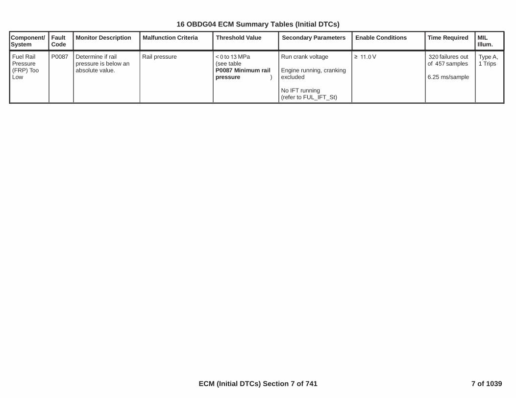
Fuel RailPressure(FRP) TooLow
P0087 Determine if railpressure is below anabsolute value.
Rail pressure < to MPa0 13(see table
)P0087 Minimum railpressure
Run crank voltage
Engine running, crankingexcluded
No IFT running(refer to )FUL_IFT_St
V11.0 failures out320of samples457
6.25 ms/sample
Type A,1 Trips
7
16 OBDG04 ECM Summary Tables (Initial DTCs)
ECM (Initial DTCs) Section 7 of 741 7 of 1039

Component/System
FaultCode
Monitor Description Malfunction Criteria Threshold Value Secondary Parameters Enable Conditions Time Required MILIllum.
FuelPressureRegulator 1Performance
P0089 Determine when railpressure is abovemaximum thresholdwhen pressure isgoverned by MeteringUnit valve.
Rail pressure > to MPa67 217(see table
)P0089 Maximum railpressure with MU
Run crank voltage
Rail pressure is governedby Metering Unit
V11.0 failures out160of samples229
OR
continuous160failures out of
samples229
6.25 ms/sample
Type A,1 Trips
8
16 OBDG04 ECM Summary Tables (Initial DTCs)
ECM (Initial DTCs) Section 8 of 741 8 of 1039

Component/System
FaultCode
Monitor Description Malfunction Criteria Threshold Value Secondary Parameters Enable Conditions Time Required MILIllum.
FuelPressureRegulatorSolenoid 1ControlCircuit
P0090 Determine when anopen circuit affectsFuel PressureRegulator 1 (MeteringUnit Valve) controlcircuit.
Impedence betweensignal and controllerground 200 k
Powertrain relay voltage
Rail pressure is governedby Metering Unit
No active DTC since keyis on:
V11.0
FHP_MU_DrvrCloseTFTKOFHP_MU_DrvrOpenTFTKO
failures out of44samples88
6.25 ms/sample
Type A,1 Trips
9
16 OBDG04 ECM Summary Tables (Initial DTCs)
ECM (Initial DTCs) Section 9 of 741 9 of 1039

Component/System
FaultCode
Monitor Description Malfunction Criteria Threshold Value Secondary Parameters Enable Conditions Time Required MILIllum.
FuelPressureRegulatorSolenoid 1ControlCircuit LowVoltage
P0091 Determine when shortcircuit to ground affectsFuel PressureRegulator 1 (MeteringUnit Valve) controlcircuit.
Impedence betweensignal and controllerground 0.5
Powertrain relay voltage
Rail pressure is governedby Metering Unit
No active DTC since keyis on:
V11.0
FHP_MU_DrvrCloseTFTKOFHP_MU_DrvrOpenTFTKO
failures out of44samples88
6.25 ms/sample
Type A,1 Trips
10
16 OBDG04 ECM Summary Tables (Initial DTCs)
ECM (Initial DTCs) Section 10 of 741 10 of 1039

Component/System
FaultCode
Monitor Description Malfunction Criteria Threshold Value Secondary Parameters Enable Conditions Time Required MILIllum.
FuelPressureRegulatorSolenoid 1ControlCircuit HighVoltage
P0092 Determine when shortcircuit to power affectsFuel PressureRegulator 1 (MeteringUnit Valve) controlcircuit.
Impedence betweensignal and controllerpower 0.5
Powertrain relay voltage
Rail pressure is governedby Metering Unit
No DTC active since keyis on:
V11.0
FHP_MU_DrvrCloseTFTKOFHP_MU_DrvrOpenTFTKO
failures out of44samples88
6.25 ms/sample
Type A,1 Trips
11
16 OBDG04 ECM Summary Tables (Initial DTCs)
ECM (Initial DTCs) Section 11 of 741 11 of 1039

Component/System
FaultCode
Monitor Description Malfunction Criteria Threshold Value Secondary Parameters Enable Conditions Time Required MILIllum.
ABS(Power Up IAT -Power Up IAT2)
AND
ABS(Power Up IAT -Power Up IAT3)
AND
ABS(Power Up IAT2 -Power Up IAT3)
> deg C25
<= deg C25
> deg C25
Time between currentignition cycle and the lasttime the engine wasrunning
Powertrain Relay Voltagefor a time
No Active DTCs:
> seconds28,800
>= Volts11.0>= seconds0.9
PowertrainRelayFaultECT_Sensor_Ckt_FAIAT_SensorCircuitFAMnfdTempSensorCktFAHumTempSnsrCktFA
Executes once atthe beginning ofeach ignitioncycle if enableconditions aremet
Intake AirTemperatureSensor 2CircuitPerformance(applicationswith IAT,IAT2 andIAT3)
P0096 Detects an IAT2 sensorthat has stuck in rangeby comparing to IATand IAT3 at startup
Type B,2 Trips
Power Up IAT isbetween Power Up IAT2and Power Up IAT3
AND
ABS(Power Up IAT2 -Power Up IAT3)
AND
ABS(Power Up IAT -Power Up IAT2) >ABS(Power Up IAT -Power Up IAT3)
> deg C25
Time between currentignition cycle and the lasttime the engine wasrunning
Powertrain Relay Voltagefor a time
No Active DTCs:
> seconds28,800
>= Volts11.0>= seconds0.9
PowertrainRelayFaultECT_Sensor_Ckt_FAIAT_SensorCircuitFAMnfdTempSensorCktFAHumTempSnsrCktFA
Executes once atthe beginning ofeach ignitioncycle if enableconditions aremet
Power Up IAT3 isbetween Power Up IATand Power Up IAT2
AND
ABS(Power Up IAT -Power Up IAT2)
AND
ABS(Power Up IAT3 -
> deg C25
Time between currentignition cycle and the lasttime the engine wasrunning
Powertrain Relay Voltagefor a time
No Active DTCs:
> seconds28,800
>= Volts11.0>= seconds0.9
PowertrainRelayFaultECT_Sensor_Ckt_FAIAT_SensorCircuitFAMnfdTempSensorCktFA
Executes once atthe beginning ofeach ignitioncycle if enableconditions aremet
12
16 OBDG04 ECM Summary Tables (Initial DTCs)
ECM (Initial DTCs) Section 12 of 741 12 of 1039

Component/System
FaultCode
Monitor Description Malfunction Criteria Threshold Value Secondary Parameters Enable Conditions Time Required MILIllum.
Power Up IAT2) >ABS(Power Up IAT3 -Power Up IAT)
HumTempSnsrCktFA
13
16 OBDG04 ECM Summary Tables (Initial DTCs)
ECM (Initial DTCs) Section 13 of 741 13 of 1039

Component/System
FaultCode
Monitor Description Malfunction Criteria Threshold Value Secondary Parameters Enable Conditions Time Required MILIllum.
Intake AirTemperatureSensorCircuit 2 Low
P0097 Detects a continuousshort to ground or openin the IAT 2 signalcircuit
Raw IAT 2 Input < Hertz13(~-60 deg C)
Powertrain Relay Voltagefor a time
No Active DTCs:
>= Volts11.0>= seconds0.9
PowertrainRelayFault
failures out40of samples50
1 sample every100 msec
Type B,2 Trips
14
16 OBDG04 ECM Summary Tables (Initial DTCs)
ECM (Initial DTCs) Section 14 of 741 14 of 1039

Component/System
FaultCode
Monitor Description Malfunction Criteria Threshold Value Secondary Parameters Enable Conditions Time Required MILIllum.
Intake AirTemperatureSensorCircuit 2High
P0098 Detects a continuoushigh frequency in theIAT 2 signal circuit
Raw IAT 2 Input > Hertz390(~150 deg C)
Powertrain Relay Voltagefor a time
No Active DTCs:
>= Volts11.0>= seconds0.9
PowertrainRelayFault
failures out40of samples50
1 sample every100 msec
Type B,2 Trips
15
16 OBDG04 ECM Summary Tables (Initial DTCs)
ECM (Initial DTCs) Section 15 of 741 15 of 1039

Component/System
FaultCode
Monitor Description Malfunction Criteria Threshold Value Secondary Parameters Enable Conditions Time Required MILIllum.
Intake AirTemperatureSensor 2IntermittentIn-Range
P0099 Detects a noisy orerratic IAT 2 signalcircuit or IAT 2 sensor
String Length
Where:"String Length" = sum of"Diff" calculated over
And where:"Diff" = ABS(current IAT 2reading - IAT 2 readingfrom 100 millisecondsprevious)
> deg C100.00
consecutive IAT 210samples
Powertrain Relay Voltagefor a time
No Active DTCs:
>= Volts11.0>= seconds0.9
PowertrainRelayFault
failures out of4samples5
Each sampletakes 1.0seconds
Type B,2 Trips
16
16 OBDG04 ECM Summary Tables (Initial DTCs)
ECM (Initial DTCs) Section 16 of 741 16 of 1039

Component/System
FaultCode
Monitor Description Malfunction Criteria Threshold Value Secondary Parameters Enable Conditions Time Required MILIllum.
Difference (absolutevalue) in measuredpressure between BAROsensor and TCIAP sensor
AND
Difference (absolutevalue) in measuredpressure between BAROsensor and MAP sensor
AND
Difference (absolutevalue) in measuredpressure between TCIAPsensor and MAP sensor
>P0106, P2227, P227B,P00C7: Maximumpressure difference[kPa]
>P0106, P2227, P227B,P00C7: Maximumpressure difference[kPa]
>P0106, P2227, P227B,P00C7: Maximumpressure difference[kPa]
Correlation diagnosticenabled by calibration
Engine is running
Cranking ignition in range
Engine speed
Requested fuel
Throttle measuredposition
Engine CoolantTemperature
OR
OBD Coolant EnableCriteria
No faults are present
==TRUE1.00
==TRUE
Battery voltage > 11.00[V]
< [rpm]1,100.00
< [mm^3]50.00
> [%]90.00
> [°C]70.00
==TRUE
CrankSensor_FA==FALSEFUL_GenericInjSysFA==FALSETPS_PstnSnsrFA==FALSEMAP_SensorCircuitFA==FALSEAAP2_SnsrCktFA==FALSEAAP_AAP5_SnsrCktFA==FALSE
320.00fail counters over400.00sample counters
sampling time is12.5 ms
Intake AirPressureMeasurement System -MultipleSensorCorrelation
P00C7 This monitor is used toidentify an ECU inputlogic fault.The plausibility monitorcompares the BARO,MAP and TCIAPpressures when theThrottle valve is open,the engine speed andthe fuel injectedquantity are below athreshold (engine idlecondition) and theengine coolanttemperature is higherthan a threshold: in thatcondition the threesensors are expectedto measure the samepressure.The monitor is able tohandle the situation inwhich the threesensors are not inagreement: in that casea DTC sets indicatingthat there is a genericfault that impacts twoor three sensors. In thiscase the monitor is notable to pinpoint thesensors that are notworking correctly.
Type A,1 Trips
16 OBDG04 ECM Summary Tables (Initial DTCs)
ECM (Initial DTCs) Section 17 of 741 17 of 1039

Component/System
FaultCode
Monitor Description Malfunction Criteria Threshold Value Secondary Parameters Enable Conditions Time Required MILIllum.
AAP_AAP2_SnsrStabFA==FALSEAAP_AAP5_SnsrStabFA==FALSEECT_Sensor_FA==FALSEMAF_MAF_SnsrFA==FALSE
Difference (absolutevalue) in measuredpressure between BAROsensor and TCIAP sensorANDDifference (absolutevalue) in measuredpressure between BAROsensor and TCIAP sensorANDDifference (absolutevalue) in measuredpressure between BAROsensor and TCIAP sensor
OR
Difference (absolutevalue) in measuredpressure between BAROsensor and TCIAP sensorANDDifference (absolutevalue) in measuredpressure between BAROsensor and TCIAP sensorANDDifference (absolutevalue) in measuredpressure between BAROsensor and TCIAP sensor
OR
> kPa10.0
<= kPa10.0
<= kPa10.0
<= kPa10.0
> kPa10.0
<= kPa10.0
Time between currentignition cycle and the lasttime the engine wasrunning
Engine is not rotating
Manifold PressureManifold PressureBaro PressureBaro PressureTCIAP PressureTCIAP Pressure
No Active DTCs:
No Pending DTCs:
> seconds5.0
>= kPa50.0<= kPa115.0>= kPa50.0<= kPa115.0>= kPa50.0<= kPa115.0
EngineModeNotRunTimerErrorMAP_SensorFAAAP_SnsrFAAAP2_SnsrFA
MAP_SensorCircuitFPAAP_SnsrCktFPAAP2_SnsrCktFP
failures out of4samples5
1 sample every12.5 msec
16 OBDG04 ECM Summary Tables (Initial DTCs)
ECM (Initial DTCs) Section 18 of 741 18 of 1039

Component/System
FaultCode
Monitor Description Malfunction Criteria Threshold Value Secondary Parameters Enable Conditions Time Required MILIllum.
Difference (absolutevalue) in measuredpressure between BAROsensor and TCIAP sensorANDDifference (absolutevalue) in measuredpressure between BAROsensor and TCIAP sensorANDDifference (absolutevalue) in measuredpressure between BAROsensor and TCIAP sensor
OR
Difference (absolutevalue) in measuredpressure between BAROsensor and TCIAP sensorANDDifference (absolutevalue) in measuredpressure between BAROsensor and TCIAP sensorANDDifference (absolutevalue) in measuredpressure between BAROsensor and TCIAP sensor
<= kPa10.0
<= kPa10.0
> kPa10.0
> kPa10.0
> kPa10.0
> kPa10.0
16 OBDG04 ECM Summary Tables (Initial DTCs)
ECM (Initial DTCs) Section 19 of 741 19 of 1039

Component/System
FaultCode
Monitor Description Malfunction Criteria Threshold Value Secondary Parameters Enable Conditions Time Required MILIllum.
ABS(Power Up IAT -Power Up IAT2)
AND
ABS(Power Up IAT -Power Up IAT3)
AND
ABS(Power Up IAT2 -Power Up IAT3)
<= deg C25
> deg C25
> deg C25
Time between currentignition cycle and the lasttime the engine wasrunning
Powertrain Relay Voltagefor a time
No Active DTCs:
> seconds28,800
>= Volts11.0>= seconds0.9
PowertrainRelayFaultECT_Sensor_Ckt_FAIAT_SensorCircuitFAMnfdTempSensorCktFAHumTempSnsrCktFA
Executes once atthe beginning ofeach ignitioncycle if enableconditions aremet
Intake AirTemperatureSensor 3CircuitPerformance
P00E9 Detects an IAT3 sensorthat has stuck in rangeby comparing to IATand IAT2 at startup
Type B,2 Trips
Power Up IAT isbetween Power Up IAT2and Power Up IAT3
AND
ABS(Power Up IAT2 -Power Up IAT3)
AND
ABS(Power Up IAT -Power Up IAT3) >ABS(Power Up IAT -Power Up IAT2)
> deg C25
Time between currentignition cycle and the lasttime the engine wasrunning
Powertrain Relay Voltagefor a time
No Active DTCs:
> seconds28,800
>= Volts11.0>= seconds0.9
PowertrainRelayFaultECT_Sensor_Ckt_FAIAT_SensorCircuitFAMnfdTempSensorCktFAHumTempSnsrCktFA
Executes once atthe beginning ofeach ignitioncycle if enableconditions aremet
Power Up IAT2 isbetween Power Up IATand Power Up IAT3
AND
ABS(Power Up IAT -Power Up IAT3)
AND
ABS(Power Up IAT2 -
> deg C25
Time between currentignition cycle and the lasttime the engine wasrunning
Powertrain Relay Voltagefor a time
No Active DTCs:
> seconds28,800
>= Volts11.0>= seconds0.9
PowertrainRelayFaultECT_Sensor_Ckt_FAIAT_SensorCircuitFAMnfdTempSensorCktFA
Executes once atthe beginning ofeach ignitioncycle if enableconditions aremet
20
16 OBDG04 ECM Summary Tables (Initial DTCs)
ECM (Initial DTCs) Section 20 of 741 20 of 1039

Component/System
FaultCode
Monitor Description Malfunction Criteria Threshold Value Secondary Parameters Enable Conditions Time Required MILIllum.
Power Up IAT3) >ABS(Power Up IAT2 -Power Up IAT)
HumTempSnsrCktFA
21
16 OBDG04 ECM Summary Tables (Initial DTCs)
ECM (Initial DTCs) Section 21 of 741 21 of 1039

Component/System
FaultCode
Monitor Description Malfunction Criteria Threshold Value Secondary Parameters Enable Conditions Time Required MILIllum.
Intake AirTemperatureSensorCircuit 3 Low
P00EA Detects a continuousshort to ground in theIAT 3 signal circuit orthe IAT 3 sensor
Raw IAT 3 Input < Ohms56(~150 deg C)
Engine Run Time > seconds0.00 failures out40of samples50
1 sample every100 msec
Type B,2 Trips
22
16 OBDG04 ECM Summary Tables (Initial DTCs)
ECM (Initial DTCs) Section 22 of 741 22 of 1039

Component/System
FaultCode
Monitor Description Malfunction Criteria Threshold Value Secondary Parameters Enable Conditions Time Required MILIllum.
Intake AirTemperatureSensorCircuit 3High
P00EB Detects a continuousopen circuit in the IAT 3signal circuit or the IAT3 sensor
Raw IAT 3 Input > Ohms151,542(~-60 deg C)
Engine Run Time > seconds0.00 failures out40of samples50
1 sample every100 msec
Type B,2 Trips
23
16 OBDG04 ECM Summary Tables (Initial DTCs)
ECM (Initial DTCs) Section 23 of 741 23 of 1039

Component/System
FaultCode
Monitor Description Malfunction Criteria Threshold Value Secondary Parameters Enable Conditions Time Required MILIllum.
Intake AirTemperatureSensor 3IntermittentIn-Range
P00EC Detects a noisy orerratic IAT 3 signalcircuit or IAT 3 sensor
String Length
Where:"String Length" = sum of"Diff" calculated over
And where:"Diff" = ABS(current IAT 3reading - IAT 3 readingfrom 100 millisecondsprevious)
> deg C80.00
consecutive IAT 310samples
Continuous failures out of4samples5
Each sampletakes 1.0seconds
Type B,2 Trips
24
16 OBDG04 ECM Summary Tables (Initial DTCs)
ECM (Initial DTCs) Section 24 of 741 24 of 1039

Component/System
FaultCode
Monitor Description Malfunction Criteria Threshold Value Secondary Parameters Enable Conditions Time Required MILIllum.
HumiditySensorCircuit Low
P00F4 Detects a continuousshort to power in theHumidity Sensor circuit
Humidity Duty Cycle <= %5.0 Powertrain Relay Voltagefor a time
No Active DTCs:
>= Volts11.0>= seconds0.9
PowertrainRelayFault
failures out40of samples50
1 sample every100 msec
Type B,2 Trips
25
16 OBDG04 ECM Summary Tables (Initial DTCs)
ECM (Initial DTCs) Section 25 of 741 25 of 1039

Component/System
FaultCode
Monitor Description Malfunction Criteria Threshold Value Secondary Parameters Enable Conditions Time Required MILIllum.
HumiditySensorCircuit High
P00F5 Detects a continuousopen or short to low inthe Humidity Sensorcircuit
Humidity Duty Cycle >= %95.0 Powertrain Relay Voltagefor a time
No Active DTCs:
>= Volts11.0>= seconds0.9
PowertrainRelayFault
failures out40of samples50
1 sample every100 msec
Type B,2 Trips
26
16 OBDG04 ECM Summary Tables (Initial DTCs)
ECM (Initial DTCs) Section 26 of 741 26 of 1039

Component/System
FaultCode
Monitor Description Malfunction Criteria Threshold Value Secondary Parameters Enable Conditions Time Required MILIllum.
HumiditySensorCircuitIntermittent
P00F6 Detects a noisy orerratic humidity sensorinput
String Length
Where:"String Length" = sum of"Diff" calculated over
And where:"Diff" = ABS(currentHumidity reading -Humidity reading from100 millisecondsprevious)
> %80
consecutive10Humidity samples
Powertrain Relay Voltagefor a time
No Active DTCs:
>= Volts11.0>= seconds0.9
PowertrainRelayFault
failures out of4samples5
Each sampletakes 1.0seconds
Type B,2 Trips
27
16 OBDG04 ECM Summary Tables (Initial DTCs)
ECM (Initial DTCs) Section 27 of 741 27 of 1039

Component/System
FaultCode
Monitor Description Malfunction Criteria Threshold Value Secondary Parameters Enable Conditions Time Required MILIllum.
Difference (absolutevalue) in measuredpressure between MAPsensor and TCIAP sensor
AND
Difference (absolutevalue) in measuredpressure between MAPsensor and BARO sensor
AND
Difference (absolutevalue) in measuredpressure between BAROsensor and TCIAP sensor
>P0106, P2227, P227B,P00C7: Maximumpressure difference[kPa]
>P0106, P2227, P227B,P00C7: Maximumpressure difference[kPa]
<P0106, P2227, P227B,P00C7: Maximumpressure difference[kPa]
Correlation diagnosticenabled by calibration
Engine is running
Cranking ignition in range
Engine speed
Requested fuel
Throttle measuredposition
Engine CoolantTemperature
OR
OBD Coolant EnableCriteria
No faults are present
==TRUE1.00
==TRUE
Battery voltage >[V]11.00
< [rpm]1,100.00
< [mm^3]50.00
> [%]90.00
> [°C]70.00
==TRUE
CrankSensor_FA==FALSEFUL_GenericInjSysFA==FALSETPS_PstnSnsrFA==FALSEMAP_SensorCircuitFA==FALSEAAP2_SnsrCktFA==FALSEAAP_AAP5_SnsrCktFA==FALSE
320.00fail counters over400.00sample counters
sampling time is12.5 ms
ManifoldAbsolutePressure(MAP)SensorPerformance
P0106 This monitor is used toidentify MAP sensorinternal faults(measurement with anoffset or a drift).The plausibility monitorcompares the BARO,MAP and TCIAPpressures when theThrottle valve is open,the engine speed andthe fuel injectedquantity are below athreshold (engine idlecondition) and theengine coolanttemperature is higherthan a threshold: in thatcondition the threesensors are expectedto measure the samepressure. If MAPsensor drifts from theother two a specificDTC sets.
Type A,1 Trips
16 OBDG04 ECM Summary Tables (Initial DTCs)
ECM (Initial DTCs) Section 28 of 741 28 of 1039

Component/System
FaultCode
Monitor Description Malfunction Criteria Threshold Value Secondary Parameters Enable Conditions Time Required MILIllum.
AAP_AAP2_SnsrStabFA==FALSEAAP_AAP5_SnsrStabFA==FALSEECT_Sensor_FA==FALSEMAF_MAF_SnsrFA==FALSE
MAP sensor
OR
MAP sensor
< kPa50.0
> kPa115.0
Time between currentignition cycle and the lasttime the engine wasrunning
Engine is not rotating
No Active DTCs:
No Pending DTCs:
> seconds5.0
EngineModeNotRunTimerError
MAP_SensorCircuitFAAAP_SnsrCktFA
MAP_SensorCircuitFPAAP_SnsrCktFP
failures out of4samples5
1 sample every12.5 msec
16 OBDG04 ECM Summary Tables (Initial DTCs)
ECM (Initial DTCs) Section 29 of 741 29 of 1039

Component/System
FaultCode
Monitor Description Malfunction Criteria Threshold Value Secondary Parameters Enable Conditions Time Required MILIllum.
ManifoldAbsolutePressureSensorCircuit Low(with pull-up)
P0107 Detects a continuousshort to low in eitherthe signal circuit or theMAP sensor.
MAP Voltage < % of 5 Volt3.0Range(This is equal to 0.15Volts or kPa)3.5
Continuous failures out320of samples400
1 sample every12.5 msec
Type B,2 Trips
30
16 OBDG04 ECM Summary Tables (Initial DTCs)
ECM (Initial DTCs) Section 30 of 741 30 of 1039

Component/System
FaultCode
Monitor Description Malfunction Criteria Threshold Value Secondary Parameters Enable Conditions Time Required MILIllum.
ManifoldAbsolutePressureSensorCircuit High(with pull-up)
P0108 Detects an opensensor ground,continuous short tohigh, or open in eitherthe signal circuit or theMAP sensor.
MAP Voltage > % of 5 Volt97.0Range(This is equal to 4.85Volts, or kPa)313.2
Continuous failures out320of samples400
1 sample every12.5 msec
Type B,2 Trips
31
16 OBDG04 ECM Summary Tables (Initial DTCs)
ECM (Initial DTCs) Section 31 of 741 31 of 1039

Component/System
FaultCode
Monitor Description Malfunction Criteria Threshold Value Secondary Parameters Enable Conditions Time Required MILIllum.
ABS(Power Up IAT -Power Up IAT2)
AND
ABS(Power Up IAT -Power Up IAT3)
AND
ABS(Power Up IAT2 -Power Up IAT3)
> deg C25
> deg C25
<= deg C25
Time between currentignition cycle and the lasttime the engine wasrunning
Powertrain Relay Voltagefor a time
No Active DTCs:
> seconds28,800
>= Volts11.0>= seconds0.9
PowertrainRelayFaultECT_Sensor_Ckt_FAIAT_SensorCircuitFAMnfdTempSensorCktFAHumTempSnsrCktFA
Executes once atthe beginning ofeach ignitioncycle if enableconditions aremet
Intake AirTemperatureSensorCircuitPerformance(applicationswith IAT,IAT2 andIAT3)
P0111 Detects an IAT sensorthat has stuck in rangeby comparing to IAT2and IAT3 at startup
Type B,2 Trips
Power Up IAT2 isbetween Power Up IATand Power Up IAT3
AND
ABS(Power Up IAT -Power Up IAT3)
AND
ABS(Power Up IAT2 -Power Up IAT) >ABS(Power Up IAT2 -Power Up IAT3)
> deg C25
Time between currentignition cycle and the lasttime the engine wasrunning
Powertrain Relay Voltagefor a time
No Active DTCs:
> seconds28,800
>= Volts11.0>= seconds0.9
PowertrainRelayFaultECT_Sensor_Ckt_FAIAT_SensorCircuitFAMnfdTempSensorCktFAHumTempSnsrCktFA
Executes once atthe beginning ofeach ignitioncycle if enableconditions aremet
Power Up IAT3 isbetween Power Up IATand Power Up IAT2
AND
ABS(Power Up IAT -Power Up IAT2)
AND
ABS(Power Up IAT3 -
> deg C25
Time between currentignition cycle and the lasttime the engine wasrunning
Powertrain Relay Voltagefor a time
No Active DTCs:
> seconds28,800
>= Volts11.0>= seconds0.9
PowertrainRelayFaultECT_Sensor_Ckt_FAIAT_SensorCircuitFAMnfdTempSensorCktFA
Executes once atthe beginning ofeach ignitioncycle if enableconditions aremet
32
16 OBDG04 ECM Summary Tables (Initial DTCs)
ECM (Initial DTCs) Section 32 of 741 32 of 1039

Component/System
FaultCode
Monitor Description Malfunction Criteria Threshold Value Secondary Parameters Enable Conditions Time Required MILIllum.
Power Up IAT) >ABS(Power Up IAT3 -Power Up IAT2)
HumTempSnsrCktFA
33
16 OBDG04 ECM Summary Tables (Initial DTCs)
ECM (Initial DTCs) Section 33 of 741 33 of 1039

Component/System
FaultCode
Monitor Description Malfunction Criteria Threshold Value Secondary Parameters Enable Conditions Time Required MILIllum.
Intake AirTemperatureSensorCircuit Low
P0112 Detects a continuousshort to ground in theIAT signal circuit or theIAT sensor
Raw IAT Input < Ohms58(~150 deg C)
Engine Run Time > seconds0.00 failures out40of samples50
1 sample every100 msec
Type B,2 Trips
34
16 OBDG04 ECM Summary Tables (Initial DTCs)
ECM (Initial DTCs) Section 34 of 741 34 of 1039

Component/System
FaultCode
Monitor Description Malfunction Criteria Threshold Value Secondary Parameters Enable Conditions Time Required MILIllum.
Intake AirTemperatureSensorCircuit High
P0113 Detects a continuousopen circuit in the IATsignal circuit or the IATsensor
Raw IAT Input > Ohms142,438(~-60 deg C)
Engine Run Time > seconds0.00 failures out40of samples50
1 sample every100 msec
Type B,2 Trips
35
16 OBDG04 ECM Summary Tables (Initial DTCs)
ECM (Initial DTCs) Section 35 of 741 35 of 1039

Component/System
FaultCode
Monitor Description Malfunction Criteria Threshold Value Secondary Parameters Enable Conditions Time Required MILIllum.
Intake AirTemperatureSensorIntermittentIn-Range
P0114 Detects a noisy orerratic IAT signal circuitor IAT sensor
String Length
Where:"String Length" = sum of"Diff" calculated over
And where:"Diff" = ABS(current IATreading - IAT readingfrom 100 millisecondsprevious)
> deg C80.00
consecutive IAT10samples
Continuous failures out of4samples5
Each sampletakes 1.0seconds
Type B,2 Trips
36
16 OBDG04 ECM Summary Tables (Initial DTCs)
ECM (Initial DTCs) Section 36 of 741 36 of 1039
Component/System
FaultCode
Monitor Description Malfunction Criteria Threshold Value Secondary Parameters Enable Conditions Time Required MILIllum.
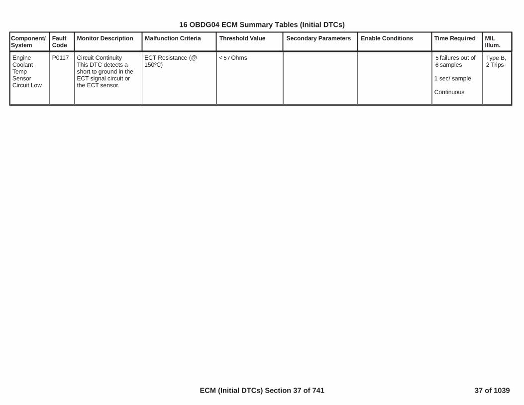
EngineCoolantTempSensorCircuit Low
P0117 Circuit ContinuityThis DTC detects ashort to ground in theECT signal circuit orthe ECT sensor.
ECT Resistance (@150ºC)
< Ohms57 failures out of5samples6
1 sec/ sample
Continuous
Type B,2 Trips
37
16 OBDG04 ECM Summary Tables (Initial DTCs)
ECM (Initial DTCs) Section 37 of 741 37 of 1039

Component/System
FaultCode
Monitor Description Malfunction Criteria Threshold Value Secondary Parameters Enable Conditions Time Required MILIllum.
EngineCoolantTempSensorCircuit High
P0118 Circuit ContinuityThis DTC detects ashort to high or open inthe ECT signal circuitor the ECT sensor.
ECT Resistance (@-60ºC)
> Ohms118,862 Engine run timeORIAT min
> seconds10.0
°C-7.0
failures out of5samples6
1 sec/ sample
Continuous
Type B,2 Trips
38
16 OBDG04 ECM Summary Tables (Initial DTCs)
ECM (Initial DTCs) Section 38 of 741 38 of 1039

Component/System
FaultCode
Monitor Description Malfunction Criteria Threshold Value Secondary Parameters Enable Conditions Time Required MILIllum.
EngineCoolantTemperature(ECT)SensorCircuitIntermittent
P0119 Circuit ContinuityThis DTC detects largestep changes in theECT signal circuit orthe ECT sensor.Allowable high and lowlimits are calculated forthe next sample basedon the previoussample.
ECT temperature stepchange:
1) postive step change isgreater than calculatedhigh limit
OR
2) negitive step change islower than calculated lowlimit.
The calculated high andlow limits for the nextreading use the followingcalibrations:1) Sensor time constant2) Sensor low limit3) Sensor high limit
*****Generic Example*****
If the last ECT readingwas 90 Deg C, the Timeconstant was calibrated at10 seconds, the low limitwas calibrated to -80 DegC and the high limit wascalibrated to 200 Deg Cthe caluculated limits are101 Deg C and 73 Deg C.
The next reading (afterthe 90 Deg C reading)must be between 73 DegC and 101 Deg C to bevalid.
seconds15.0Deg C-80.0Deg C200.0
No Active DTC's ECT_Sensor_Ckt_FP failures out of3samples4
1 sec/ sample
Continuous
Type B,2 Trips
39
16 OBDG04 ECM Summary Tables (Initial DTCs)
ECM (Initial DTCs) Section 39 of 741 39 of 1039

Component/System
FaultCode
Monitor Description Malfunction Criteria Threshold Value Secondary Parameters Enable Conditions Time Required MILIllum.
EngineCoolantTemperatureBelow StatRegulatingTemperature) (energybased"Deluxe"method
P0128 This DTC detects if theengine coolanttemperature rises tooslowly due to an ECTor Cooling system fault
Energy is accumulatedafter the first conbustionevent using Range #1 or#2 below:
Thermostat type is dividedinto normal (non-heated)and electrically heated.
For this application the"type" cal(KeTHMG_b_TMS_ElecThstEquipped) = 0If the type cal is equal toone, the application hasan electrically heated t-stat, if equal to zero thethe application has an nonheated t-stat. Seeappropiate section below.
*****************************Type cal above = 1(Electrically heated t-stat)== == == ==Range #1 (Primary) ECTreaches Commandedtemperature minus °C19when Ambient min is
°C and > °C.52 10Note: Warm up target forrange #1 will be at least
°C69== == == ==Range #2 (Alternate) ECTreaches Commandedtemperature minus °C50when Ambient min is
°C and > °C.10 -7Note: Warm up target forrange #2 will be at least
See the two tablesnamed:P0128_MaximumAccumulated Energyfor Start-up ECTconditions - PrimaryandP0128_MaximumAccumulated Energyfor Start-up ECTconditions - Alternatein the Supportingtables section.
This diagnostic modelsthe net energy into andout of the cooling
No Active DTC's
Engine not run time(soaking time beforecurrent trip)
Engine run time
Fuel Condition
Distance traveled
***************************If Engine RPM iscontinuously greater thanfor this time period
The diagnostic test for thiskey cycle will abort***************************
***************************If T-Stat Heatercommanded duty cyclefor this time period
ECT_Sensor_Ckt_FAECT_Sensor_Perf_FAVehicleSpeedSensor_FAOAT_PtEstFiltFAIAT_SensorCircuitFAMAF_SensorFATHMR_AWP_AuxPumpFATHMR_AHV_FATHMR_SWP_Control_FATHMR_SWP_NoFlow_FATHMR_SWP_FlowStuckOn_FAEngineTorqueEstInaccurate
seconds1,800
Eng Run Tme 20seconds1,450
Ethanol %87
miles0.50
***************************
rpm9,999seconds5.0
***************************
***************************
> % duty cycle20.0> seconds5.0
1 failure to setDTC
1 sec/ sample
Once per ignitionkey cycle
Type B,2 Trips
41
16 OBDG04 ECM Summary Tables (Initial DTCs)
ECM (Initial DTCs) Section 40 of 741 40 of 1039

Component/System
FaultCode
Monitor Description Malfunction Criteria Threshold Value Secondary Parameters Enable Conditions Time Required MILIllum.
°C55
*****************************Type cal above = 0(non - heated t-stat)== == == ==Range #1 (Primary) ECTreaches °C when69Ambient min is
°C and > °C.52 10== == == ==
Range #2 (Alternate) ECTreaches °C when55Ambient min is
°C and > °C.10 -7
*****************************
system during thewarm-up process.
The five energy termsare: heat fromcombustion (with AFMcorrection), heat fromafter-run, heat loss toenviroment, heat lossto cabin and heat lossto DFCO.
The diagnostic test for thiskey cycle will abort
***************************ECT at start run
*************************** ECT °C-40 64
42
16 OBDG04 ECM Summary Tables (Initial DTCs)
ECM (Initial DTCs) Section 41 of 741 41 of 1039

Component/System
FaultCode
Monitor Description Malfunction Criteria Threshold Value Secondary Parameters Enable Conditions Time Required MILIllum.
FuelTemperatureSensor APerformance
P0181 Determine when fueltemperature sensor isnot plausible, due tooffset or drift.
Absolute differencebetween fuel temperatureand referencetemperature (seeP0181 Fuel TemperatureSensor Reference)
> °C to °C20.0 20.0(see table
)
P0181 FuelTemperaturePlausibility
Run crank voltage
Run crank voltage
Engine not cranking
A timeandis passed since enginemovement is detected
Engine soak time
No error for Engine NotRunning timer(refer toEngineModeNotRunTimerError
No DTC active:
(Engine coolanttemperature
ORECT_OBD_GlobalCoolTmpEnbl(refer to "OBD CoolantEnable Criteria" section))
> V6.0
V11.0
> s8< s13
> s28,799
= FALSE)
FTS_FTS_CktFAFTS_PlausRefSnsrFlt
> °C-40
= TRUE
1 sample
100 ms/sample
Type B,2 Trips
43
16 OBDG04 ECM Summary Tables (Initial DTCs)
ECM (Initial DTCs) Section 42 of 741 42 of 1039

Component/System
FaultCode
Monitor Description Malfunction Criteria Threshold Value Secondary Parameters Enable Conditions Time Required MILIllum.
FuelTemperatureSensor ACircuit Low
P0182 Determine when ashort circuit to groundaffects fuel temperaturesensor.
Fuel temperature sensoroutput resistance < 50
Run crank voltage
Run crank voltage
Engine not cranking
> V6.0
V11.0
failures out of10samples20
100 ms/samples
Type B,2 Trips
44
16 OBDG04 ECM Summary Tables (Initial DTCs)
ECM (Initial DTCs) Section 43 of 741 43 of 1039
Component/System
FaultCode
Monitor Description Malfunction Criteria Threshold Value Secondary Parameters Enable Conditions Time Required MILIllum.
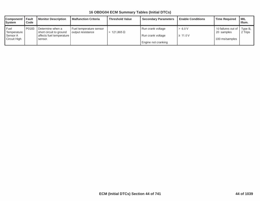
FuelTemperatureSensor ACircuit High
P0183 Determine when ashort circuit to groundaffects fuel temperaturesensor.
Fuel temperature sensoroutput resistance > 121,865
Run crank voltage
Run crank voltage
Engine not cranking
> V6.0
V11.0
failures out of10samples20
100 ms/samples
Type B,2 Trips
45
16 OBDG04 ECM Summary Tables (Initial DTCs)
ECM (Initial DTCs) Section 44 of 741 44 of 1039

Component/System
FaultCode
Monitor Description Malfunction Criteria Threshold Value Secondary Parameters Enable Conditions Time Required MILIllum.
Fuel temperature > (1 ) * °C +156(Last good sample * )
with = e^[- (amountof consecutive badsamples * )]0.01
Run crank voltage
Run crank voltage
No active DTC:
> V6.0
V11.0
FTS_FTS_CktFA
failures out of10samples15
100 ms/samples
FuelTemperatureSensor ACircuitIntermittent
P0184 Determine when fueltemperature sensorchanges quicker thanexpected, likely due toan intermittent fault.
Type B,2 Trips
Fuel temperature < (1 ) * °C +-56(Last good sample * )
with = e^[- (amountof consecutive badsamples * )]0.01
Run crank voltage
Run crank voltage
No active DTC:
> V6.0
V11.0
FTS_FTS_CktFA
failures out of10samples15
100 ms/samples
46
16 OBDG04 ECM Summary Tables (Initial DTCs)
ECM (Initial DTCs) Section 45 of 741 45 of 1039

Component/System
FaultCode
Monitor Description Malfunction Criteria Threshold Value Secondary Parameters Enable Conditions Time Required MILIllum.
Rail pressure sensoroutput (as percentage ofsupply voltage)
OR
Rail pressure sensoroutput (as percentage ofsupply voltage)
> %14.0
< %6.5
Engine off time
No error for Engine NotRunning timer(refer toEngineModeNotRunTimerError
No engine movementdetected since begin ofdriving cycle
(Engine coolanttemperature
ORECT_OBD_GlobalCoolTmpEnbl(refer to "OBD CoolantEnable Criteria" section))
Run crank voltage
Run crank voltage
No active DTC:
s35
= FALSE)
°C-40
= TRUE
> V6.0
V11.0
ECT_Sensor_FAFHP_RPS_CktFA
failures out of42samples60
6.25 ms/sample
Fuel RailPressure(FRP)Sensor APerformance
P0191 Determine when fuelrail pressure sensor isnot plausible, due tooffset or drift.
Type A,1 Trips
Absolute differencebetween rail pressure #1(first trace) and railpressure #2 (secondtrace) > MPa21.0
P0191 Rail PressureSensor Configuration
Run crank voltage
Run crank voltage
No active DTC:
=CeFHPG_e_RPS_DoubleTrack
> V6.0
V11.0
FHP_RPS_CktFAP0194
failures out of33samples55
6.25 ms/sample
47
16 OBDG04 ECM Summary Tables (Initial DTCs)
ECM (Initial DTCs) Section 46 of 741 46 of 1039

Component/System
FaultCode
Monitor Description Malfunction Criteria Threshold Value Secondary Parameters Enable Conditions Time Required MILIllum.
Fuel RailPressure(FRP)Sensor ACircuit LowVoltage
P0192 Determine when ashort circuit to groundaffects fuel railpressure sensor.
Fuel rail pressure sensoroutput (as percentage ofsupply voltage) < %4.3
Starter motor is notengagedOR
Starter motor has beenengaged for a timeOR
Run crank voltageRuncrank voltage
s15
> V8.4
failures out of38samples76
OR
continuous22failures out of
samples76
6.25 ms/samples
Type A,1 Trips
48
16 OBDG04 ECM Summary Tables (Initial DTCs)
ECM (Initial DTCs) Section 47 of 741 47 of 1039

Component/System
FaultCode
Monitor Description Malfunction Criteria Threshold Value Secondary Parameters Enable Conditions Time Required MILIllum.
Fuel RailPressure(FRP)Sensor ACircuit HighVoltage
P0193 Determine when ashort circuit to voltageaffects fuel railpressure sensor.
Fuel rail pressure sensoroutput (as percentage ofsupply voltage) < %94.8
Starter motor is notengagedOR
Starter motor has beenengaged for a timeOR
Run crank voltageRuncrank voltage
s15
> V8.4
failures out of38samples76
OR
continuous22failures out of
samples76
6.25 ms/samples
Type A,1 Trips
49
16 OBDG04 ECM Summary Tables (Initial DTCs)
ECM (Initial DTCs) Section 48 of 741 48 of 1039

Component/System
FaultCode
Monitor Description Malfunction Criteria Threshold Value Secondary Parameters Enable Conditions Time Required MILIllum.
Fuel RailPressure(FRP)Sensor ACircuitIntermittent
P0194 Determine when railpressure sensorchanges quicker thanexpected, likely due toan intermittent fault.
Absolute difference twoconsecutive rail pressuresamples > MPa15.0
Run crank voltage
Run crank voltage
Engine not cranking
No DTC active since keyis on:
> V6.0
V11.0
FHP_RPS_CktTFTKOFHP_RPS_OfstTFTKO
failures out of80samples115
6.25 ms/sample
Type X,No MIL
50
16 OBDG04 ECM Summary Tables (Initial DTCs)
ECM (Initial DTCs) Section 49 of 741 49 of 1039

Component/System
FaultCode
Monitor Description Malfunction Criteria Threshold Value Secondary Parameters Enable Conditions Time Required MILIllum.
For this application the"type" cal(KeTHMG_b_TMS_ElecThstEquipped) = 0
If the type cal is equal toone, the application hasan electrically heated t-stat, if equal to zero thethe application has an nonheated t-stat. Seeappropiate section below.
*****************************Type cal above = 0(non - heated t-stat)== == == ==
Engine coolanttemperature*****************************
Type cal above = 1(Electrically heated t-stat)== == == ==
Engine coolanttemperature
Deg C68.0
Deg C70.5
No Active DTC's
Engine Runtime
Distance traveled this keycycle
Ambient air pressure
Ambient air temperature
**************************Engine coolanttemperatureAt least once during thekey cycle
Type 0 (non-heated t-stat)
Type 1 (Electricallyheated T-stat)
**************************Heat to coolant
DFCO time
Thermostat duty cycle
ECT_Sensor_Ckt_FAVehicleSpeedSensor_FAOAT_PtEstFiltFATHMR_AWP_AuxPumpFATHMR_AHV_FATHMR_SWP_Control_FAEngineTorqueEstInaccurateECT_Sensor_Perf_FATHMR_SWP_NoFlow_FATHMR_SWP_FlowStuckOn_FA
seconds30.0
km1.2
kPa55.0
Deg C-7.0
Deg C69
to Deg C71.5 86.5
kW20.0
seconds2.0
%20.0
failures out30of samples60
1 sample /second
Continuous
CoolantTemperatureDroppedBelowDiagnosticMonitoringTemperature
P01F0 This DTC detects anunexplained systemcool down below theOBD monitoringthreshold during normaloperating conditions
Type B,2 Trips
51
16 OBDG04 ECM Summary Tables (Initial DTCs)
ECM (Initial DTCs) Section 50 of 741 50 of 1039

Component/System
FaultCode
Monitor Description Malfunction Criteria Threshold Value Secondary Parameters Enable Conditions Time Required MILIllum.
Boost pressure trackingerror (difference betweenthe desired boostpressure and themeasured pressure atintake manifold by MAPsensor) lower than athreshold.
The setpoint used forclosed loop control is theintake manifold pressure:in this situation thediagnostic monitors theboost pressure closedloop control tracking error.
<(P0234: Negativeboost deviationthreshold (throttlecontrol not active)[kPa]
x
P0234, P2263:Overboostbarometric correction)
Calibration on diagnosticenabling
Engine Running
Cranking ignition in range
Relay voltage in range
Difficult launch NOTdetected
Boost Pressure ControlClosed Loop active
No active transition fromone combustion mode toanother
Outside Air Temperature
Desired Boost Pressuresteady state:BstDes-BstDes_Old
Engine speed
P0234, P0299: Boostpressure controldeviation enabling==TRUE
==TRUE
Battery voltage > 11.00[V]
Powertrain relay voltage >[V]11.00
Refer to"LDT_DifficultLaunchActive" Free Form
==TRUEAIC_BstCntrlCL
==TRUE
> [°C]-7.00AND< [°C]55.00
> [kPa/s]-18AND< [kPa/s]24
> [rpm]1,800.00
fail counters320over sample400counters
sampling time is25ms
Turbocharger/Supercharger "A"OverboostCondition
P0234 This monitor detectsfailures in the chargingair system such to notfulfil the request ofboost pressure in theintake manifold. Itworks only in steadystate closed looppressure control zone.The DTC checks apermanent negativecontrol deviation of theboost pressureindicating an overboostcondition.This monitor is used todetect any malfunctionin the boost pressuresystem causing thevehicle's emissions toexceed the limits.The aim of the boostoverboost pressuremonitor is to detectobstructions in theexhaust pipe. Theboost pressure isusually controlled bythe VGT vanes. Theintake manifoldpressure is alsoaffected by the throttlevalve and the EGRvalve position changes.The aim of thisprocedure is to identifya limitation of the VGTvanes (equal to anobstruction) that leadsto exceed the emissionlimits.
Type B,2 Trips
52
16 OBDG04 ECM Summary Tables (Initial DTCs)
ECM (Initial DTCs) Section 51 of 741 51 of 1039

Component/System
FaultCode
Monitor Description Malfunction Criteria Threshold Value Secondary Parameters Enable Conditions Time Required MILIllum.
Desired intake Boostpressure
Engine CoolantTemperatureOROBD Coolant EnableCriteria,ANDEngine CoolantTemperature
Ambient Air Pressure
Throttle Valve position
No active DTCs
Timer delay once allabove conditions are
AND< [rpm]2,550.00
>P0234: Minimum boostpressure for overboostmonitor enabling[kPa]AND
<
P0234: Maximum boostpressure for overboostmonitor enabling
[kPa]
> [°C]70
==TRUE
< [°C]117
> [kPa]70AND< [kPa]110
>= [%]75.00
AIC_BstSysDiagDenomDsbl==FALSE
>P0234: Overboostmonitor delay timer
53
16 OBDG04 ECM Summary Tables (Initial DTCs)
ECM (Initial DTCs) Section 52 of 741 52 of 1039

Component/System
FaultCode
Monitor Description Malfunction Criteria Threshold Value Secondary Parameters Enable Conditions Time Required MILIllum.
fulfilled [s]
Boost pressure trackingerror(difference betweenthe desired boostpressure and themeasured pressure atintake manifold by MAPsensor) lower than athreshold.
The setpoint used forclosed loop control is theconversion of the desiredupstream throttle boostpressure (target) indesired intake boostpressure.The conversion of thesetpoint is donecalculating the pressuredrop over the throttlevalve that is strictlydependent on the valveposition.
<(P0234: Negativeboost deviationthreshold (throttlecontrol active)[kPa]
x
P0234, P2263:Overboostbarometric correction)
Calibration on diagnosticenabling
Engine Running
Cranking ignition in range
Relay voltage in range
Difficult launch NOTdetected
Boost Pressure ControlClosed Loop active
No active transition fromone combustion mode toanother
Outside Air Temperature
Desired Boost Pressuresteady state:
P0234, P0299: Boostpressure controldeviation enabling==TRUE
==TRUE
Battery voltage >[V]11.00
Powertrain relay voltage >[V]11.00
Refer to"LDT_DifficultLaunchActive" Free Form
==TRUEAIC_BstCntrlCL
==TRUE
> [°C]-7.00AND< [°C]55.00
> [kPa/s]-18AND
fail counters320over sample400counters
sampling time is25ms
54
16 OBDG04 ECM Summary Tables (Initial DTCs)
ECM (Initial DTCs) Section 53 of 741 53 of 1039

Component/System
FaultCode
Monitor Description Malfunction Criteria Threshold Value Secondary Parameters Enable Conditions Time Required MILIllum.
BstDes-BstDes_Old
Engine speed
Desired intake Boostpressure
Engine CoolantTemperatureOROBD Coolant EnableCriteria,ANDEngine CoolantTemperature
Ambient Air Pressure
Throttle Valve position
No active DTCs
< [kPa/s]24
> [rpm]1,800.00AND< [rpm]2,550.00
>P0234: Minimum boostpressure for overboostmonitor enabling[kPa]AND
<
P0234: Maximum boostpressure for overboostmonitor enabling
[kPa]
> [°C]70
==TRUE
< [°C]117
> [kPa]70AND< [kPa]110
>= [%]100.00
AIC_BstSysDiagDenomDsbl==FALSE
55
16 OBDG04 ECM Summary Tables (Initial DTCs)
ECM (Initial DTCs) Section 54 of 741 54 of 1039

Component/System
FaultCode
Monitor Description Malfunction Criteria Threshold Value Secondary Parameters Enable Conditions Time Required MILIllum.
Timer delay once allabove conditions arefulfilled
>P0234: Overboostmonitor delay timer[s]
56
16 OBDG04 ECM Summary Tables (Initial DTCs)
ECM (Initial DTCs) Section 55 of 741 55 of 1039

Component/System
FaultCode
Monitor Description Malfunction Criteria Threshold Value Secondary Parameters Enable Conditions Time Required MILIllum.
Boost pressure trackingerror(difference betweenthe desired boostpressure and themeasured pressure atintake manifold by MAPsensor) higher than athreshold.
The setpoint used forclosed loop control is theintake manifold pressure:in this situation thediagnostic monitors theboost pressure closedloop control tracking error.
>(P0299: Positive boostdeviation threshold(throttle control notactive)[kPa]
x
P0299, P2263:Underboostbarometric correction)
Calibration on diagnosticenabling
Engine Running
Cranking ignition in range
Relay voltage in range
Difficult launch NOTdetected
Boost Pressure ControlClosed Loop active
No active transition fromone combustion mode toanother
Outside Air Temperature
Desired Boost Pressuresteady state:BstDes-BstDes_Old
Engine speed
P0234, P0299: Boostpressure controldeviation enabling==TRUE
==TRUE
Battery voltage >[V]11.00
Powertrain relay voltage >[V]11.00
Refer to"LDT_DifficultLaunchActive" Free Form
==TRUEAIC_BstCntrlCL
==TRUE
> [°C]-7.00AND< [°C]55.00
> [kPa/s]-18AND< [kPa/s]24
> [rpm]1,250.00
fail320.00counters over
sample400.00counters
sampling time is25ms
Turbocharger/Supercharger "A"UnderboostCondition
P0299 Type B,2 Trips
16 OBDG04 ECM Summary Tables (Initial DTCs)
ECM (Initial DTCs) Section 56 of 741 56 of 1039

Component/System
FaultCode
Monitor Description Malfunction Criteria Threshold Value Secondary Parameters Enable Conditions Time Required MILIllum.
Desired intake Boostpressure
Engine CoolantTemperatureOROBD Coolant EnableCriteria,ANDEngine CoolantTemperature
Ambient Air Pressure
Throttle Valve position
No active DTCs
Timer delay once allabove conditions are
AND< [rpm]2,000.00
>P0299: Minimum boostpressure for underboostmonitor enabling[kPa]AND<P0299: Maximum boostpressure for underboostmonitor enabling[kPa]
> [°C]70
==TRUE
< [°C]117
> [kPa]70AND< [kPa]110
>= [%]75.00
AIC_BstSysDiagDenomDsbl==FALSE
>P0299: Underboostmonitor delay timer
This monitor detectsfailures in the chargingair system such to notfulfil the request ofboost pressure in theintake manifold. Itworks only in steadystate closed looppressure control zone.The DTC checks apermanent positivecontrol deviation of theboost pressureindicating anunderboost condition.This monitor is used todetect any malfunctionin the boost pressuresystem causing thevehicle's emissions toexceed the limits.The aim of theunderboost pressuremonitor is to detectleakages in the pipeafter the compressor orin the intake/exhaustmanifold. The boostpressure is usuallycontrolled by the VGTvanes. The intakemanifold pressure isalso affected by thethrottle valve and theEGR valve positionchanges. The aim ofthis procedure is toidentify a limitation ofthe VGT vanes (equalto a leakage) that leadsto exceed the emission
16 OBDG04 ECM Summary Tables (Initial DTCs)
ECM (Initial DTCs) Section 57 of 741 57 of 1039

Component/System
FaultCode
Monitor Description Malfunction Criteria Threshold Value Secondary Parameters Enable Conditions Time Required MILIllum.
fulfilled [s]limits.
Boost pressure trackingerror(difference betweenthe desired boostpressure and themeasured pressure atintake manifold by MAPsensor) higher than athreshold.
The setpoint used forclosed loop control is theconversion of the desiredupstream throttle boostpressure (target) indesired intake boostpressure.The conversion of thesetpoint is donecalculating the pressuredrop over the throttlevalve that is strictlydependent on the valveposition.
>(P0299: Positive boostdeviation threshold(throttle controlactive)[kPa]
x
P0299, P2263:Underboostbarometric correction)
Calibration on diagnosticenabling
Engine Running
Cranking ignition in range
Relay voltage in range
Difficult launch NOTdetected
Boost Pressure ControlClosed Loop active
No active transition fromone combustion mode toanother
Outside Air Temperature
Desired Boost Pressuresteady state:BstDes-BstDes_Old
P0234, P0299: Boostpressure controldeviation enabling==TRUE
==TRUE
Battery voltage > 11.00[V]
Powertrain relay voltage >[V]11.00
Refer to"LDT_DifficultLaunchActive" Free Form
==TRUEAIC_BstCntrlCL
==TRUE
> [°C]-7.00AND< [°C]55.00
> [kPa/s]-18AND< [kPa/s]24
fail320.00counters over
sample400.00counters
sampling time is25ms
16 OBDG04 ECM Summary Tables (Initial DTCs)
ECM (Initial DTCs) Section 58 of 741 58 of 1039

Component/System
FaultCode
Monitor Description Malfunction Criteria Threshold Value Secondary Parameters Enable Conditions Time Required MILIllum.
Engine speed
Desired intake Boostpressure
Engine CoolantTemperatureOROBD Coolant EnableCriteria,ANDEngine CoolantTemperature
Ambient Air Pressure
Throttle Valve position
No active DTCs
> [rpm]1,250.00AND< [rpm]2,000.00
>P0299: Minimum boostpressure for underboostmonitor enabling[kPa]AND<P0299: Maximum boostpressure for underboostmonitor enabling[kPa]
> [°C]70
==TRUE
< [°C]117
> [kPa]70AND< [kPa]110
>= [%]100.00
AIC_BstSysDiagDenomDsbl==FALSE
16 OBDG04 ECM Summary Tables (Initial DTCs)
ECM (Initial DTCs) Section 59 of 741 59 of 1039

Component/System
FaultCode
Monitor Description Malfunction Criteria Threshold Value Secondary Parameters Enable Conditions Time Required MILIllum.
Timer delay once allabove conditions arefulfilled
>P0299: Underboostmonitor delay timer[s]
16 OBDG04 ECM Summary Tables (Initial DTCs)
ECM (Initial DTCs) Section 60 of 741 60 of 1039

Component/System
FaultCode
Monitor Description Malfunction Criteria Threshold Value Secondary Parameters Enable Conditions Time Required MILIllum.
RandomMisfireDetected
Cylinder 1MisfireDetected
Cylinder 2MisfireDetected
Cylinder 3MisfireDetected
Cylinder 4MisfireDetected
P0300
P0301
P0302
P0303
P0304
These DTC’s willdetermine if a randomor a cylinder specificmisfire is occurring bymonitoring variousterms derived fromcrankshaft velocity.The rate of misfire overan interval is comparedto both emissions andcatalyst damagingthresholds. Thepattern of crankshaftacceleration after themisfire is checked todifferentiate betweenreal misfire and othersources of crank shaftnoise.
Crankshaft DecelerationValue(s) vs.Engine Speed andEngine load
The equation used tocalculate decelerationvalue is tailored to specificvehicle operatingconditions.The selection of theequation used is based onthe 1st single cylindercontinuous misfirethreshold tablesencountered that are notmax of range. If all tablesare max of range at agiven speed/load, thatspeed load region is anUndetectable regionsee Algorithm DescriptionDocument for additionaldetails.
SINGLE CYLINDERCONTINUOUS MISFIRE(
(Medres_DecelMedres_Jerk
OR (Medres_DecelMedres_Jerk
OR (Lores_DecelLores_Jerk
OR (Lores_DecelLores_Jerk
OR RevBalanceTime)
- see details ofthresholds onSupporting Tables Tab
> ANDIdleSCD_Decel> )IdleSCD_Jerk
> ANDSCD_Decel> )SCD_Jerk
> ANDIdleCyl_Decel> )IdleCyl_Jerk
> ANDCylModeDecel> )CylModeJerk
>RevMode_Decel
Engine Run Time
Engine Coolant TempOr If ECT at startupThen ECT
System Voltage+ Throttle delta- Throttle delta
Early Termination option:(used on plug ins thatmay not have enoughengine run time at end oftrip for normal interval tocomplete.)
> 2 crankshaft revolution
ºC < ECT < ºC-7 125< ºC-7
ºC < ECT < ºC21 125
< volts <9.00 32.00< % per 25 ms100.00< % per 25 ms100.00
Not Enabled
EmissionExceedence =any ( ) failed5200 rev blocksout of ( ) 20016rev block tests
Failure reportedfor ( )1Exceedence in1st ( ) 200 rev16block tests, or( )4Exceedencesthereafter.
ORwhen EarlyTerminationReporting =Enabled andengine rev> revs1,000and < 3,200revs at end oftrip
any CatalystExceedence =( ) 200 rev1block as datasupports forcatalyst damage.
Type B,2 Trips(MilFlasheswithCatalystdamagelevel ofMisfire)
16 OBDG04 ECM Summary Tables (Initial DTCs)
ECM (Initial DTCs) Section 61 of 741 61 of 1039

Component/System
FaultCode
Monitor Description Malfunction Criteria Threshold Value Secondary Parameters Enable Conditions Time Required MILIllum.
*******************************Feature only used onDiesel engines
Combustion Modes thatforce selection of IdleTables******************************
Other patterns of misfireuse adjustments to thesingle cylinder continuousmisfire threshold tables:
RANDOM MISFIREUse random misfire
thresholds If no misfire for
(Medres_Decel
ANDMedres_Jerk)
OR (Medres_Decel
ANDMedres_Jerk)
OR (Lores_Decel
ANDLores_Jerk)
OR (Lores_Decel
***************************Feature only used onDiesel engines
CombustModeIdleTblin Supporting Tables
**************************
> Engine Cycles3
> *IdleSCD_DecelRandom_SCD_Decel
> *IdleSCD_JerkRandom_SCD_Jerk
> *SCD_DecelRandom_SCD_Decel
> *SCD_JerkRandom_SCD_Jerk
> *IdleCyl_DecelRandomCylModDecel
> *IdleCyl_JerkRandomCylModJerk
> *CylModeDecel
Catalyst Failurereported with (1or 3)Exceedences inFTP, or (1)Exceedenceoutside FTP.
Continuous
16 OBDG04 ECM Summary Tables (Initial DTCs)
ECM (Initial DTCs) Section 62 of 741 62 of 1039

Component/System
FaultCode
Monitor Description Malfunction Criteria Threshold Value Secondary Parameters Enable Conditions Time Required MILIllum.
ANDLores_Jerk)
OR RevBalanceTime
PAIRED CYLINDERMISFIREIf a cylinder & it's pair areabove PAIR thresholds
(Medres_Decel
ANDMedres_Jerk)
OR (Medres_Decel
ANDMedres_Jerk)
OR (Lores_Decel
ANDLores_Jerk)
OR (Lores_Decel
ANDLores_Jerk)
OR (Revmode Active AND
RandomCylModDecel
> *CylModeJerkRandomCylModJerk
> *RevMode_DecelRandomRevModDecl
> *IdleSCD_DecelPair_SCD_Decel
> *IdleSCD_JerkPair_SCD_Jerk
> *SCD_DecelPair_SCD_Decel
> *SCD_JerkPair_SCD_Jerk
> *IdleCyl_DecelPairCylModeDecel
> *IdleCyl_JerkPairCylModeJerk
> *CylModeDecelPairCylModeDecel
> *CylModeJerkPairCylModeJerk
16 OBDG04 ECM Summary Tables (Initial DTCs)
ECM (Initial DTCs) Section 63 of 741 63 of 1039

Component/System
FaultCode
Monitor Description Malfunction Criteria Threshold Value Secondary Parameters Enable Conditions Time Required MILIllum.
(within one engine cycle:2nd largest Lores_Decel)
ANDAbove TRUE for) )
BANK MISFIRECylinders aboveBank Thresholds
(Medres_Decel
ANDMedres_Jerk)
OR (Medres_Decel
ANDMedres_Jerk)
OR (Lores_Decel
ANDLores_Jerk)
OR (Lores_Decel
ANDLores_Jerk)
> *CylModeDecelPairCylModeDecel
> engine cycles out35of 100 engine cycles
>= cylinders3
> *IdleSCD_DecelBank_SCD_Decel
> *IdleSCD_JerkBank_SCD_Jerk
> *SCD_DecelBank_SCD_Decel
> *SCD_JerkBank_SCD_Jerk
> *IdleCyl_DecelBankCylModeDecel
> *IdleCyl_JerkBankCylModeJerk
> *CylModeDecelBankCylModeDecel
> *CylModeJerkBankCylModeJerk
16 OBDG04 ECM Summary Tables (Initial DTCs)
ECM (Initial DTCs) Section 64 of 741 64 of 1039

Component/System
FaultCode
Monitor Description Malfunction Criteria Threshold Value Secondary Parameters Enable Conditions Time Required MILIllum.
CONSECUTIVECYLINDER MISFIRE
1st cylinder usessingle cyl continuousmisfire thresholds;2nd Cylinder uses:
(Medres_Decel
ANDMedres_Jerk)
OR (Medres_Decel
ANDMedres_Jerk)
OR (Lores_Decel
ANDLores_Jerk)
OR (Lores_Decel
ANDLores_Jerk)
CYLINDERDEACTIVATION MODE(Active Fuel Managment)
AFM: SINGLE CYLINDER
> *IdleSCD_DecelConsecSCD_Decel
> *IdleSCD_JerkConsecSCD_Jerk
> *SCD_DecelConsecSCD_Decel
> *SCD_JerkConsecSCD_Jerk
> *IdleCyl_DecelConsecCylModDecel
> *IdleSCD_JerkConsecCylModeJerk
> *CylModeDecelConsecCylModDecel
> *CylModeJerkConsecCylModeJerk
16 OBDG04 ECM Summary Tables (Initial DTCs)
ECM (Initial DTCs) Section 65 of 741 65 of 1039

Component/System
FaultCode
Monitor Description Malfunction Criteria Threshold Value Secondary Parameters Enable Conditions Time Required MILIllum.
CONTINUOUS MISFIRE(CylAfterDeacCyl_Decel
ANDCylAfterDeacCyl_Jerk)
OR(CylBeforeDeacCylDecel
ANDCylBeforeDeacCyl_Jerk)
AFM: RANDOM MISFIREUse random misfire
thresholds If no misfire for
(CylAfterDeacCyl_Decel
ANDCylAfterDeacCyl_Jerk)
(CylBeforeDeacCylDecel
ANDCylBeforeDeacCyl_Jerk)
> *CylModeDecelClyAfterAFM_Decel
> *CylModeJerkCylAfterAFM_Jerk
> *CylModeDecelCylBeforeAFM_Decel
> *CylModeJerkClyBeforeAFM_Jerk
> Engine Cycles3
> *CylModeDecel*ClyAfterAFM_Decel
RandomAFM_Decl
> *CylModeJerk*CylAfterAFM_Jerk
RandomAFM_Jerk
> *CylModeDecelCylBeforeAFM_Decel* RandomAFM_Decl
> *CylModeJerkClyBeforeAFM_Jerk
* RandomAFM_Jerk
- see details onSupporting Tables Tab
16 OBDG04 ECM Summary Tables (Initial DTCs)
ECM (Initial DTCs) Section 66 of 741 66 of 1039

Component/System
FaultCode
Monitor Description Malfunction Criteria Threshold Value Secondary Parameters Enable Conditions Time Required MILIllum.
Misfire Percent EmissionFailure Threshold
Misfire Percent CatalystDamage
When engine speed andload are less than theFTP cals (3) catalystdamage exceedences areallowed.
% P03005.00
>Catalyst_Damage_Misfire_Percentagein Supporting Tableswhenever secondaryconditions are met.
FTP rpm AND0 FTP % load10
disable conditions:
(at low speed/loads, onecylinder may not causecat damage)
Engine SpeedEngine LoadMisfire counts
Engine Speed
No active DTCs:
> rpm AND1,000> % load AND20< counts on one180cylinder
< rpm < ((Engine580Over Speed Limit) - )400OR )8,191
Engine speed limit is afunction of inputs likeGear and temperature
seeEngineOverSpeedLimitin supporting tables
TPS_FAEnginePowerLimited
cycle delay4
cycle delay4
16 OBDG04 ECM Summary Tables (Initial DTCs)
ECM (Initial DTCs) Section 67 of 741 67 of 1039

Component/System
FaultCode
Monitor Description Malfunction Criteria Threshold Value Secondary Parameters Enable Conditions Time Required MILIllum.
P0315 & engine speed
Fuel Level Low
Cam and Crank Sensors
Misfire requests TCCunlock
Fuel System Status
Active FuelManagement
Undetectable enginespeed and engine loadregion
Abusive Engine OverSpeed
Below zero torque (exceptCARB approved 3000rpm to redline triangle.)
MAF_SensorTFTKOMAP_SensorTFTKOIAT_SensorTFTKOECT_Sensor_Ckt_TFTKO5VoltReferenceB_FACrankSensor_TFTKOCrankSensor_FACamLctnIntFACamLctnExhFACamSensorAnyLctnTFTKOAnyCamPhaser_FAAnyCamPhaser_TFTKOAmbPresDfltdStatus
> rpm1,000
LowFuelConditionDiagnosticin sync with each other
Not honored becauseTransmission in hot modeor POPD intrusivediagnostic running
Fuel Cut
Transition in progress
Undetectable regionfrom Malfunction Criteria
> rpm8,192
< ZeroTorqueEngLoador < ifZeroTorqueAFMAFM is active
cycle delay4
cycle delay500
cycle delay4
cycle delay4
cycle delay4
cycle delay0
cycle delay4
cycle delay0
cycle delay4
16 OBDG04 ECM Summary Tables (Initial DTCs)
ECM (Initial DTCs) Section 68 of 741 68 of 1039

Component/System
FaultCode
Monitor Description Malfunction Criteria Threshold Value Secondary Parameters Enable Conditions Time Required MILIllum.
Below zero torque:TPS
Vehicle Speed
NEGATIVE TORQ AFMIf deactivated cylindersappear to make power,torque is negative:
DeactivatedCyl_DecelAND
DeactivatedCyl_JerkAND
# of Deact Cyls Inverted
EGR Intrusive test
Manual Trans
Accel Pedal PositionAND Automatictransmission shift
After Fuel resumes onAutomatic shift containingFuel Cut
Delay if PTO engaged
*******************************Feature only used onDiesel engines
Combustion Mode
in Supporting Tables
% ( % in100.0 2.0AFM)> mph (> mph AFM)19 19
<DeacCylInversionDecel
<DeacCylInversionJerk
> cylinders0
Active
Clutch shift
> %1.00
Enabled
******************************
cycle delay4
cycle delay0
cycle delay12
cycle delay4
cycle delay0
Cylinder delay2
cycle delay4
*******************
cycle delay4
16 OBDG04 ECM Summary Tables (Initial DTCs)
ECM (Initial DTCs) Section 69 of 741 69 of 1039

Component/System
FaultCode
Monitor Description Malfunction Criteria Threshold Value Secondary Parameters Enable Conditions Time Required MILIllum.
Driver cranks before Waitto Start lamp extinguishes
Brake Torque******************************
DRIVELINE RING FILTERAfter a low level misfire,another misfire may notbe detectable untildriveline ringing ceases.If no ringing seen, stopfilter early.
Filter Driveline ring:
Stop filter early:
ABNORMAL ENGINESPEED OSCILLATION:(checks each "misfire"candidate in 100 engineCycle test to see if it lookslike some disturbance likerough road (abnormal). )
Used Off Idle, and whilenot shifting,
TPSEngine Speed
Veh SpeedAuto Transmission
indivdual candidatedeemed abnormal if
= valueInfrequentRegenin Supporting Tables
IF TRUE
> % Max Torque199.99******************************
> " " # ofRing Filterengine cycles after misfirein Supporting Tables
> " "Number of Normals# of engine cycles aftermisfire in SupportingTables tab
> %200> rpm1,000> mph3not shifting
WaitToStartcycle delay
cycle delay4*******************
16 OBDG04 ECM Summary Tables (Initial DTCs)
ECM (Initial DTCs) Section 70 of 741 70 of 1039

Component/System
FaultCode
Monitor Description Malfunction Criteria Threshold Value Secondary Parameters Enable Conditions Time Required MILIllum.
number ofconsecutive deceleratingcylinders after "misfire":(Number of decels canvary with misfire detectionequation)
Consecutive decelswhile in SCD Mode
Cyl ModeRev Mode
At the end of 100 enginecycle test, the ratio ofabnormal/candidate ischecked to confirm if realmisfire is present withinthe 100 engine cycles.
abnormal candidates/total candidates
MISFIRE CRANKSHAFTPATTERNRECOGNITIONchecks each "misfire"candidate in 100 engineCycle test to see if overallcrankshaft pattern lookslike real misfire(recognized), or somedisturbance like roughroad (unrecognized).At the end of 100 enginecycle test, the ratio ofunrecog/recognized ischecked to confirm if real
> Abnormal SCD Mode> Abnormal Cyl Mode> Abnormal Rev Modein Supporting Tables
> ratio0.50
discard 100engine cycle test
16 OBDG04 ECM Summary Tables (Initial DTCs)
ECM (Initial DTCs) Section 71 of 741 71 of 1039

Component/System
FaultCode
Monitor Description Malfunction Criteria Threshold Value Secondary Parameters Enable Conditions Time Required MILIllum.
misfire is present withinthe 100 engine cycles.Typically used forchecking a single misfireper engine cycle but cansupport some otherpatterns on somepackages
Pattern Recog Enabled:
Pattern Recog Enabledduring Cylinder Deac
Pattern Recog Enabledconsecutive cyl pattrn
Engine SpeedVeh Speed
The 1st check for"recognized" is the 1stfired cylinder after themisfire candidate shouldboth accelerate and jerkan amount basedacceleration and jerk ofSingle Cylinder Misfirethresholds in effect at thatspeed and load.
(CylAfter_AccelAND
CylAfter_Jerk)
Enabled
Not Enabled
Enabled
< rpm <700 6,800> mph0.6
> Misfire_ decel *1st_FireAftrMisfr_Acel
> Misfire_Jerk *1st_FireAftrMisfr_Jerk
Or if AFM mode is active:> Misfire_ decel *1stFireAftrMisAcelAFM> Misfire_Jerk *1stFireAfterMisJerkAFM
16 OBDG04 ECM Summary Tables (Initial DTCs)
ECM (Initial DTCs) Section 72 of 741 72 of 1039

Component/System
FaultCode
Monitor Description Malfunction Criteria Threshold Value Secondary Parameters Enable Conditions Time Required MILIllum.
Addtionally, the crankhaftis checked again a smallcalibratible number ofcylinders later to see if thedistrubance is still largelike rough road, or hascalmed down like realmisfire. The size ofdisturbance is comparedto a multiplier times theddt_jerk value used todetect misfire at thatspeed and load. If there isrepetitive misfire onconsecutive enginecycles, the expected snapis adjusted due to thehigher expecteddisturbance.
Num of Cylinders aftermisfire to start check ofcrankshaft snap
"misfire" recognized if:Crankshaft snap after:
isolated "misfire"
repetative "misfire"
At the end of 100 enginecycle test, the ratio ofunrecog/recognized ischecked to confirm if realmisfire is present.
Ratio of Unrecog/Recog
Cylinders2
< Misfire_Jerk *SnapDecayAfterMisfire
< Misfire_Jerk **SnapDecayAfterMisfire
RepetSnapDecayAdjstin Supporting Tables
> 1.00
discard 100engine cycle test
16 OBDG04 ECM Summary Tables (Initial DTCs)
ECM (Initial DTCs) Section 73 of 741 73 of 1039

Component/System
FaultCode
Monitor Description Malfunction Criteria Threshold Value Secondary Parameters Enable Conditions Time Required MILIllum.
:NON-CRANKSHAFTBASED ROUGH ROAD:
Rough Road Source
IF Rough Road Source= WheelSpeedInECM
ABS/TCSWheel speed noise
VSES
IF Rough Road Source= "FromABS"
ABS/TCSRoughRoadVSES
IF Rough Road Source= "TOSS"
TOSS dispersion
AND No Active DTCs
Disabled
CeRRDR_e_None
active> WSSRoughRoadThresactive
activedetectedactive
>TOSSRoughRoadThresin supporting tables
Transmission OutputShaft Angular VelocityValidityTransmissionEngagedState_FA(Auto Trans only)ClutchPstnSnsr FA(Manual Trans only)
discard 100engine cycle test
discard 100engine cycle test
discard 100engine cycle test
cycle delay4
16 OBDG04 ECM Summary Tables (Initial DTCs)
ECM (Initial DTCs) Section 74 of 741 74 of 1039

Component/System
FaultCode
Monitor Description Malfunction Criteria Threshold Value Secondary Parameters Enable Conditions Time Required MILIllum.
CrankshaftPositionSystemVariation NotLearned
P0315 Monitor for validcrankshaft tooth values
Differance between 360degrees and the sum ofthe reluctor wheel's teeth
> degrees0.001 OBD ManufacturerEnable Counter
MEC = 0 seconds0.50
FrequencyContinuous100msec
Type A,1 Trips
76
16 OBDG04 ECM Summary Tables (Initial DTCs)
ECM (Initial DTCs) Section 75 of 741 75 of 1039

Component/System
FaultCode
Monitor Description Malfunction Criteria Threshold Value Secondary Parameters Enable Conditions Time Required MILIllum.
Time since last crankshaftposition sensor pulsereceived >= seconds4.0
Starter engagedAND(cam pulses beingreceivedOR( MAF_SensorFAANDEngine Air Flow
= FALSE
> grams/second ) )2.0
Continuousevery 100 msec
CrankshaftPosition(CKP)Sensor ACircuit
P0335 Determines if a faultexists with the crankposition sensor signal
Type A,1 Trips
No crankshaft pulsesreceived >= seconds0.3
Engine is Running
Starter is not engaged
Continuousevery 12.5 msec
No crankshaft pulsesreceived
Engine is RunningORStarter is engaged
No DTC Active: P0340P0341
failures out2of samples10
One sample perengine revolution
77
16 OBDG04 ECM Summary Tables (Initial DTCs)
ECM (Initial DTCs) Section 76 of 741 76 of 1039

Component/System
FaultCode
Monitor Description Malfunction Criteria Threshold Value Secondary Parameters Enable Conditions Time Required MILIllum.
Time in which or10more crank re-synchronizations occur < seconds10.0
Engine Air Flow
Cam-based engine speed
No DTC Active:
>= grams/second2.0
> RPM450
P0335
Continuousevery 250 msec
CrankshaftPosition(CKP)Sensor APerformance
P0336 Determines if aperformance faultexists with the crankposition sensor signal
Type A,1 Trips
No crankshaftsynchronizationgap found >= seconds0.4
Engine is Running
Starter is not engaged
Continuousevery 12.5 msec
Time since starterengaged withoutdetecting crankshaftsynchronization gap >= seconds1.5
Starter engagedAND(cam pulses beingreceivedOR( MAF_SensorFAANDEngine Air Flow
= FALSE
> grams/second ) )2.0
Continuousevery 100 msec
Crank pulses received inone engine revolutionORCrank pulses received inone engine revolution
< 51
> 65
Engine is RunningORStarter is engaged
No DTC Active: P0340P0341
failures out8of samples10
One sample perengine revolution
78
16 OBDG04 ECM Summary Tables (Initial DTCs)
ECM (Initial DTCs) Section 77 of 741 77 of 1039

Component/System
FaultCode
Monitor Description Malfunction Criteria Threshold Value Secondary Parameters Enable Conditions Time Required MILIllum.
Time since last camshaftposition sensor pulsereceived
OR
Time that starter has beenengaged without acamshaft sensor pulse
>= seconds5.5
>= seconds4.0
Starter engagedAND(crank pulses beingreceivedOR( MAF_SensorFAANDEngine Air Flow
= FALSE
> grams/second ) )2.0
Continuousevery 100 msec
CamshaftPosition(CMP)SensorCircuit Bank1 Sensor A
P0340 Determines if a faultexists with the camposition bank 1 sensorA signal
Type A,1 Trips
Fewer than camshaft4pulses received in a time > seconds3.0
Engine is running
Starter is not engaged
Continuousevery 100 msec
No camshaft pulsesreceived during first
MEDRES events12(There are 12MEDRES events perengine cycle
Crankshaft issynchronized
Starter must beengaged to enable thediagnostic, but thediagnostic will notdisable when thestarter is disengaged
No DTC Active: CrankSensor_FA
Continuousevery MEDRESevent
The number of camshaftpulses received during
engine cycles100 = 0
Crankshaft issynchronized
No DTC Active: CrankSensor_FA
failures out of8samples10
Continuousevery enginecycle
79
16 OBDG04 ECM Summary Tables (Initial DTCs)
ECM (Initial DTCs) Section 78 of 741 78 of 1039

Component/System
FaultCode
Monitor Description Malfunction Criteria Threshold Value Secondary Parameters Enable Conditions Time Required MILIllum.
The number of camshaftpulses received duringfirst MEDRES events12isOR
(There are 12MEDRES events perengine cycle)
< 4> 6
Crankshaft issynchronized
Starter must be engagedto enable the diagnostic,but the diagnostic willnot disable when thestarter is disengaged
No DTC Active: CrankSensor_FA
Continuousevery MEDRESevent
CamshaftPosition(CMP)SensorPerformanceBank 1Sensor A
P0341 Determines if aperformance faultexists with the camposition bank 1 sensorA signal
Type A,1 Trips
The number of camshaftpulses received during
engine cycles100OR
< 398> 402
Crankshaft issynchronized
No DTC Active: CrankSensor_FA
failures out of8samples10
Continuousevery enginecycle
80
16 OBDG04 ECM Summary Tables (Initial DTCs)
ECM (Initial DTCs) Section 79 of 741 79 of 1039

Component/System
FaultCode
Monitor Description Malfunction Criteria Threshold Value Secondary Parameters Enable Conditions Time Required MILIllum.
Air mass tracking error:difference between thefresh air requested (setpoint) and the fresh airmeasured by MAF sensor.
>P0400: EGR flowperformancethreshold (air masstracking error)[mg]
System performancediagnostic enabled bycalibration
Engine Running
Cranking ignition in range
Relay voltage in range
Air Control is Active (aircontrol in closed loop)
Desired EGR rate
A transition betweendifferent combustionmodes is ended
Engine speed is steadystate: |RPM-RPM_old|
for a minimum number ofsamples
Fuel request is steadystate: |FUEL-FUEL_old|
for a minimum number ofsamples
==TRUE1.00
==TRUE
Battery voltage >[V]11.00
Powertrain relay voltage >[V]11.00
AIC_AirCntrlShtOffAction==Ce_AICR_e_CntrlActv
> 0 [%]
==TRUE
> [rpm]6AND< [rpm]21
> [counts]50
> [mm^3]]0.10AND< [mm^3]1.00
> [counts]50
fail179.00counters over
sample360.00counters
sampling time is25 ms
Exhaust GasRecirculation(EGR)SystemPerformance
P0400 This monitor detectsfailures in the airsystem such to lead toan excessive EGR flowrate through the intakemanifold that couldlead to clog the DPF orjerk the engine. Itworks both when EGRflow is managed with amass air flow requestor with an O2concentration request(the mass air flow erroris always calculated).This monitor is used todetect any malfunctionin the air system thatlead to very high EGRrate that could lead todamage the intakemanifold or the EGRcooler outlet pipe.The monitor shall notoverlap with theExcessive EGR flowemission correlatedmonitor.
Type B,2 Trips
81
16 OBDG04 ECM Summary Tables (Initial DTCs)
ECM (Initial DTCs) Section 80 of 741 80 of 1039
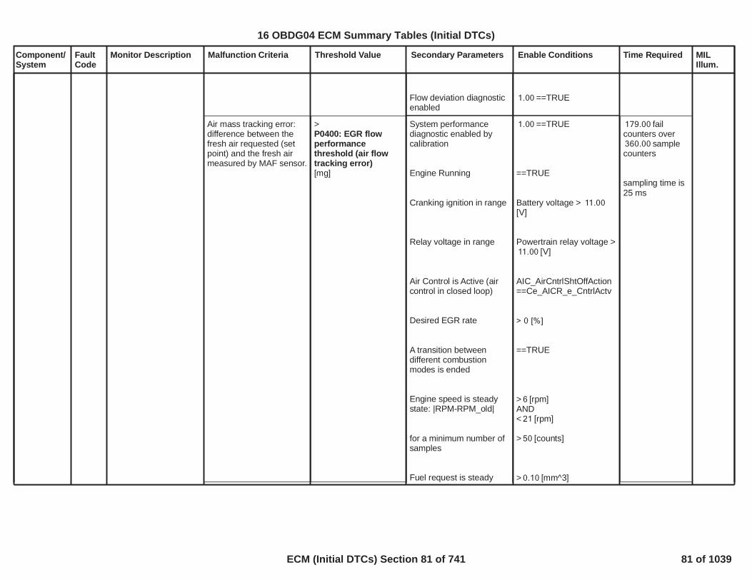
Component/System
FaultCode
Monitor Description Malfunction Criteria Threshold Value Secondary Parameters Enable Conditions Time Required MILIllum.
Flow deviation diagnosticenabled
==TRUE1.00
Air mass tracking error:difference between thefresh air requested (setpoint) and the fresh airmeasured by MAF sensor.
>P0400: EGR flowperformancethreshold (air flowtracking error)[mg]
System performancediagnostic enabled bycalibration
Engine Running
Cranking ignition in range
Relay voltage in range
Air Control is Active (aircontrol in closed loop)
Desired EGR rate
A transition betweendifferent combustionmodes is ended
Engine speed is steadystate: |RPM-RPM_old|
for a minimum number ofsamples
Fuel request is steady
==TRUE1.00
==TRUE
Battery voltage > 11.00[V]
Powertrain relay voltage >[V]11.00
AIC_AirCntrlShtOffAction==Ce_AICR_e_CntrlActv
> 0 [%]
==TRUE
> [rpm]6AND< [rpm]21
> [counts]50
> [mm^3]0.10
fail179.00counters over
sample360.00counters
sampling time is25 ms
82
16 OBDG04 ECM Summary Tables (Initial DTCs)
ECM (Initial DTCs) Section 81 of 741 81 of 1039

Component/System
FaultCode
Monitor Description Malfunction Criteria Threshold Value Secondary Parameters Enable Conditions Time Required MILIllum.
state: |FUEL-FUEL_old|
for a minimum number ofsamples
Flow deviation diagnosticenabled
AND< [mm^3]1.00
> [counts]50
==TRUE1.00
83
16 OBDG04 ECM Summary Tables (Initial DTCs)
ECM (Initial DTCs) Section 82 of 741 82 of 1039

Component/System
FaultCode
Monitor Description Malfunction Criteria Threshold Value Secondary Parameters Enable Conditions Time Required MILIllum.
Exhaust GasRecirculation(EGR) Flowinsufficient(for OBDIImarket)
P0401 This monitor detectsfailures in the airsystem such to not fulfilthe request of mass airflow through the intakecircuit. It works bothwhen EGR flow ismanaged with a massair flow request or withan O2 concentrationrequest (the mass airflow error is alwayscalculated).This monitor is used todetect any malfunctionin the air system thatlead to higher/lowerEGR rate causing thevehicle's emissions toexceed the emissionlimits.The aim of the EGRflow monitor is to detectHP EGR obstructions(insufficient EGR flow).The EGR flow dependson several variableslike the HP EGR valveposition, intakemanifold pressure,exhaust pressure, EGRcooler outlettemperature. The aimof this procedure is toidentify a limitation ofthe HP EGR (equal toan obstruction) thatleads to exceed theOBDII limits.
Air mass tracking error:difference between thefresh air requested (setpoint) and the fresh airmeasured by MAF sensor.
<
(SeaBaro ConstantxP0401: InsufficientEGR flow barometrictable B (sea level)[mg])
+
(MidBaro ConstantxP0401: InsufficientEGR flow barometrictable B (mid level)[mg]
)
+
(LoBaro ConstantxP0401: InsufficientEGR flow barometrictable B (low level)[mg])
+
(SeaBaro Constantx
Calibration on diagnosticenabling
Flow deviation diagnosticenabled by calibration
Engine Running
Cranking ignition in range
Relay voltage in range
Air Control is Active (aircontrol in closed loop)
Engine speed is steadystate: |RPM-RPM_old|
for a minimum number ofsamples
Fuel request is steadystate: |FUEL-FUEL_old|
for a minimum number ofsamples
Desired EGR rate
P0401, P0402: EGR flowmonitor enabling==TRUE
==TRUE1.00
==TRUE
Battery voltage > 11.00[V]
Powertrain relay voltage >[V]11.00
AIC_AirCntrlShtOffAction==Ce_AICR_e_CntrlActv
> [rpm]6AND< [rpm]21
> [counts]50
> [mm^3]0.10AND< [mm^3]1.00
> [counts]50
> 0 [%]
fail320.00counters over
sample400.00counters
sampling time is25 ms
Type B,2 Trips
84
16 OBDG04 ECM Summary Tables (Initial DTCs)
ECM (Initial DTCs) Section 83 of 741 83 of 1039

Component/System
FaultCode
Monitor Description Malfunction Criteria Threshold Value Secondary Parameters Enable Conditions Time Required MILIllum.
P0401: InsufficientEGR flow barometrictable A (sea level)[mg]xP0401: InsufficientEGR flow barometriccorrection (sea level))
+
(MidBaro ConstantxP0401: InsufficientEGR flow barometrictable A (mid level)[mg]xP0401: InsufficientEGR flow barometriccorrection (mid level))
+
(LoBaro ConstantxP0401: InsufficientEGR flow barometrictable A (low level)[mg]xP0401: InsufficientEGR flow barometriccorrection (low level))
A transition betweendifferent combustionmodes is endedORDisabled by calibration
A combustion modetransition is NOT active
Throttle measuredposition
Desired EGR flow
Desired fuel quantity
Engine speed
Outside air temperature
Ambient air pressure
OBD Coolant EnableCriteria
No faults on proper
==TRUEOR
==TRUE1.00
==TRUE
> [%]90.00
>
[mg]P0401: Minimumdesired EGR flow
> [mm^3]10.00AND< [mm^3]25.00
> [rpm]1,600.00AND< [rpm]1,900.00
> [°C]-7.00
> [kPa]69.60
==TRUE
85
16 OBDG04 ECM Summary Tables (Initial DTCs)
ECM (Initial DTCs) Section 84 of 741 84 of 1039

Component/System
FaultCode
Monitor Description Malfunction Criteria Threshold Value Secondary Parameters Enable Conditions Time Required MILIllum.
temperature sensor
All Enabling conditionslast for a time
AIC_EGR_FlowDiagAirTempFA==FALSE
> [s]1.00
86
16 OBDG04 ECM Summary Tables (Initial DTCs)
ECM (Initial DTCs) Section 85 of 741 85 of 1039

Component/System
FaultCode
Monitor Description Malfunction Criteria Threshold Value Secondary Parameters Enable Conditions Time Required MILIllum.
Exhaust GasRecirculation(EGR) Flowexcessive(for OBDIImarket)
P0402 It detects excessiveEGR flow. Actual MAFreadings are comparedto desired fresh airmass values as anindication of how muchEGR is flowing.Thismonitor detects failuresin the air system suchto not fulfil the requestof mass air flowthrough the intakecircuit. It works bothwhen EGR flow ismanaged with a massair flow request or withan O2 concentrationrequest (the mass airflow error is alwayscalculated).This monitor is used todetect any malfunctionin the air system thatlead to higher/lowerEGR rate causing thevehicle's emissions toexceed the emissionlimits.The aim of the EGRflow monitor is to detectHP EGR valveleakages (excessiveEGR flow). The EGRflow depends onseveral variables likethe HP EGR valveposition, intakemanifold pressure,exhaust pressure, EGRcooler outlettemperature. The aim
Air mass tracking error:difference between thefresh air requested (setpoint) and the fresh airmeasured by MAF sensor.
>
(SeaBaro ConstantxP0402: ExcessiveEGR flow barometrictable B (sea level)[mg])
+
(MidBaro ConstantxP0402: ExcessiveEGR flow barometrictable B (mid level)[mg])
+
(LoBaro ConstantxP0402: ExcessiveEGR flow barometrictable B (low level)[mg])
+
(SeaBaro Constantx
Calibration on diagnosticenabling
Flow deviation diagnosticenabled by calibration
Engine Running
Cranking ignition in range
Relay voltage in range
Air Control is Active (aircontrol in closed loop)
Engine speed is steadystate: |RPM-RPM_old|
for a minimum number ofsamples
Fuel request is steadystate: |FUEL-FUEL_old|
for a minimum number ofsamples
Desired EGR rate
P0401, P0402: EGR flowmonitor enabling==TRUE
==TRUE1.00
==TRUE
Battery voltage > 11.00[V]
Powertrain relay voltage >[V]11.00
AIC_AirCntrlShtOffAction==Ce_AICR_e_CntrlActv
> [rpm]6AND< [rpm]21
> [counts]50
> [mm^3]0.10AND< [mm^3]1.00
> [counts]50
> 0 [%]
fail375.00counters over
sample500.00counters
sampling time is25 ms
Type B,2 Trips
87
16 OBDG04 ECM Summary Tables (Initial DTCs)
ECM (Initial DTCs) Section 86 of 741 86 of 1039

Component/System
FaultCode
Monitor Description Malfunction Criteria Threshold Value Secondary Parameters Enable Conditions Time Required MILIllum.
of this procedure is toidentify a limitation ofthe HP EGR (equal to aleakage) that leads toexceed the OBDIIlimits.
P0402: ExcessiveEGR flow barometrictable A (sea level)[mg]xP0402: ExcessiveEGR flow barometriccorrection (sea level))
+
(MidBaro ConstantxP0402: ExcessiveEGR flow barometrictable A (mid level)[mg]xP0402: ExcessiveEGR flow barometriccorrection (mid level))
+
(LoBaro ConstantxP0402: ExcessiveEGR flow barometrictable A (low level)[mg]xP0402: ExcessiveEGR flow barometriccorrection (low level))
A transition betweendifferent combustionmodes is endedORDisabled by calibration
A combustion modetransition is not active
Throttle measuredposition
Desired EGR flow
Desired fuel quantity
Engine speed
Outside air temperature
Ambient air pressure
OBD Coolant EnableCriteria
==TRUEOR
==TRUE1.00
==TRUE
> [%]90.00
<
[mg]P0402: Maximumdesired EGR flow
> [mm^3]45.00AND< [mm^3]65.00
> [rpm]1,550.00AND< [rpm]1,950.00
> [°C]-7.00
> [kPa]69.60
==TRUE
88
16 OBDG04 ECM Summary Tables (Initial DTCs)
ECM (Initial DTCs) Section 87 of 741 87 of 1039

Component/System
FaultCode
Monitor Description Malfunction Criteria Threshold Value Secondary Parameters Enable Conditions Time Required MILIllum.
No faults on propertemperature sensor
All Enabling conditionslast for a time
AIC_EGR_FlowDiagAirTempFA==FALSE
> [s]1.00
89
16 OBDG04 ECM Summary Tables (Initial DTCs)
ECM (Initial DTCs) Section 88 of 741 88 of 1039

Component/System
FaultCode
Monitor Description Malfunction Criteria Threshold Value Secondary Parameters Enable Conditions Time Required MILIllum.
Warm UpCatalystEfficiencyBelowThresholdBank 1
P0421 The Catalyst (CC DOC)monitor only runsduring DPFregeneration andcompares the CC DOCreleased oxidation heatand the post-injectedfuel quantity bothevaluated inside adetermined portion ofthe DPF regenerationitself. This comparison(ratio) produces anAging Index that shallbe greater than theefficiency threshold, incase of fresh (efficient)Catalyst. If, instead, theso calculated AgingIndex is below theefficiency threshold, thediagnosis reports failcause the Catalyst istoo much damaged toplay well its role(conversion inefficiencydetected) and shall bereplaced.It is needed that post-injection is enabledduring CC DOCmonitor in order toproduce enoughexothermic heat acrossthe Catalyst to evaluatethe componentconversion efficiency ina reliable way.
EWMA Filteringfunctionality (including
Catalyst Aging Index <Threshold
If- Catalyst EWMA filterenabling calibration =TRUEAND- Catalyst conversioninefficiency previouslydetected (Catalyst FaultActive = TRUE)Then:Catalyst Aging Index <Threshold
Aging Index <CatCrtdEffThrsh[Curve]
IfEWMA Enbl Cal =
[Boolean]0.00
ANDCatalyst FA =CAT_CatSysEffLoB1_FA
Then:Aging Index <CatCrtdEffRepEWMA[Curve]
- Catalyst monitorenabling calibration =TRUEANDNo active DTCs:- Catalyst up temperaturesensor not in fault (FaultFlag = FALSE)AND- Catalyst downtemperature sensor not infault (Fault Flag =FALSE);
Temperature Learningconcluded:- Number of elapsedsamples (task time = 100[ms]) equal to calibration;
Catalyst monitor status isDISABLED if:
- DPF regenerationdisabled
OR- Injection system in fault(Fault Flag = TRUE)OR- Ambient temperatureinformation in fault (FaultActive = TRUE)OR- Catalyst up exhaust flowestimation in fault (FaultFlag = TRUE)
Monitor Enbl Cal = 1.00[Boolean]
AND
Cat Up Temp Snsr Flt =NOT ( )EGT_SnsrCatUpFlt
ANDCat Dwn Temp Snsr Flt =NOT( );EGT_SnsrCatDwnFlt
Samples nr. = 10.00[Counter];
VeCATD_e_CatSt =TeCATR_e_CatMontrSt.CeCATD_e_MontrDsbld[Enumerative]
=DPF_DPF_StTeDPFR_e_DPF_St.CeDPFR_e_SootLoading[Enumerative]ORInjection System Flt =FUL_GenericInjSysFltORAmb Temp FA =CAT_OutsideTempFA
ORCat Up Exh Flow Flt =EXF_TotExhCatUpFlt
Task Time = 100[ms]
If- Catalyst EWMAfilter enablingcailibration =FALSE (EWMAEnbl Cal = 0.00[Boolean])Then:2 trips (withmalfunction) toset DTC (TypeB)
If- Catalyst EWMAfilter enablingcailibration =TRUE (EWMAEnbl Cal = 0.00[Boolean])AND- EWMA status =EWMA Standard(NeCATD_e_EWMA_CalcStatCatEff =TeCATR_e_Status_EWMA.CeCATR_e_EWMA_Standard)Then:1 trip (withmalfunction) toset DTC (Type A)
Type B,2 Trips
90
16 OBDG04 ECM Summary Tables (Initial DTCs)
ECM (Initial DTCs) Section 89 of 741 89 of 1039

Component/System
FaultCode
Monitor Description Malfunction Criteria Threshold Value Secondary Parameters Enable Conditions Time Required MILIllum.
Fast Initial Response(FIR), Rapid Response(RR) and EWMAStandard) is supportedby the Catalyst (CCDOC) monitor.
In MY16 sw thementioned monitor onlyruns in the followingbelow exhaustconfiguration (NAXLDE):-C_UI_SCR_HCI_C_DPF: Close Coupled DOC(Catalyst) --> UreaInjector --> SelectiveCatalyst Reduction -->Hydro Carbon Injector--> Under Floor DOC(Second Catalyst) -->Diesel Particulate FIlter
OR- Ambient pressure lowerthan calibrationOR- Ambient temperaturelower than calibrationOR- Catalyst monitor alreadyperformed successfully incurrent driving cycle(Catalyst monitor shall runonly once per drivingcycle)ORHC unloading enabled;
Catalyst monitor statuscan move fromDISABLED toTRIGGERED if:- DPF regenerationenabled
AND- Injection system not infault (Fault Flag = FALSE)
AND- Ambient temperatureinformation not in fault(Fault Active = FALSE)AND- Catalyst up exhaust flowestimation not in fault(Fault Flag = FALSE)AND- Ambient pressure higherthan calibrationAND
ORAmb Press < [KPa]70.00
ORAmb Temp < [K]266.00
ORCatalyst monitor alreadyperformed successfully incurrent driving cycle(Catalyst monitor shall runonly once per drivingcycle) [Boolean]OR
=HCI_DeHC_ExhInjDsblTRUE [Boolean];
VeCATD_e_CatSt =TeCATR_e_CatMontrSt.CeCATD_e_MontrTrg[Enumerative]DPF_DPF_StTeDPFR_e_DPF_St.CeDPFR_e_SootLoading[Enumerative]ANDInjection System Flt =NOT( )FUL_GenericInjSysFltANDAmb Temp FA = NOT( )CAT_OutsideTempFA
ANDCat Up Exh Flow Flt =NOT( )EXF_TotExhCatUpFltANDAmb Press > [KPa]70.00
AND
If- Catalyst EWMAfilter enablingcailibration =TRUE (EWMAEnbl Cal = 0.00[Boolean])AND- EWMA status =Fast InitialResponse (FIR)(NeCATD_e_EWMA_CalcStatCatEff =TeCATR_e_Status_EWMA.CeCATR_e_EWMA_FIR)Then:- 1 trip (withmalfunction) toset DTC (Type A)and return toEWMA status =EWMA Standard(NeCATD_e_EWMA_CalcStatCatEff =TeCATR_e_Status_EWMA.CeCATR_e_EWMA_Standard)- [Counter]0.00elapsed trips(with nomulfunction) toreport pass andreturn to EWMAstatus = EWMAStandard(NeCATD_e_EWMA_CalcStatCat
91
16 OBDG04 ECM Summary Tables (Initial DTCs)
ECM (Initial DTCs) Section 90 of 741 90 of 1039

Component/System
FaultCode
Monitor Description Malfunction Criteria Threshold Value Secondary Parameters Enable Conditions Time Required MILIllum.
- Ambient temperaturehigher than calibrationAND- Catalyst monitor not yetperformed successfully incurrent driving cycle(Catalyst monitor shall runonly once per drivingcycle)AND- IfDPF regeneration hasbeen interrupted inprevious driving cycle orin current driving cycleThen:Engine coolanttemperature lower thancalibrationAND- Catalyst up exhausttemperature (by sensor)lower than calibration;
Catalyst monitor statuscan move fromTRIGGERED toENABLED (oxidation heatrelease integrator andpost injected fuelintegrator are bothenabled) if:- DPF regenerationenabled
AND- Injection system not infault (Fault Flag = FALSE)
AND
Amb Temp > [K]266.00
ANDCatalyst monitor not yetperformed successfully incurrent driving cycle(Catalyst monitor shall runonly once per drivingcycle) [Boolean]ANDIfInterrupted DPFregeneration counter > 0[Counter]
Then:Eng Cool Temp < 255.99[°C]
ANDCat Up Temp Snsr <
[K];1,500.00
VeCATD_e_CatSt =TeCATR_e_CatMontrSt.CeCATD_e_MontrEnbl[Enumerative]
DPF_DPF_StTeDPFR_e_DPF_St.CeDPFR_e_SootLoading[Enumerative]ANDInjection System Flt =NOT( )FUL_GenericInjSysFltAND
Eff =TeCATR_e_Status_EWMA.CeCATR_e_EWMA_Standard)
If- Catalyst EWMAfilter enablingcailibration =TRUE (EWMAEnbl Cal = 0.00[Boolean])AND- EWMA status =Rapid Response(RR)(NeCATD_e_EWMA_CalcStatCatEff =TeCATR_e_Status_EWMA.CeCATR_e_EWMA_RR)Then:- 1 trip (withmalfunction) toset DTC (Type A)and return toEWMA status =EWMA Standard(NeCATD_e_EWMA_CalcStatCatEff =TeCATR_e_Status_EWMA.CeCATR_e_EWMA_Standard)- 1 trip (with nomulfunction) toreport pass
92
16 OBDG04 ECM Summary Tables (Initial DTCs)
ECM (Initial DTCs) Section 91 of 741 91 of 1039

Component/System
FaultCode
Monitor Description Malfunction Criteria Threshold Value Secondary Parameters Enable Conditions Time Required MILIllum.
- Ambient temperatureinformation not in fault(Fault Active = FALSE)AND- Catalyst up exhaust flowestimation not in fault(Fault Flag = FALSE)AND- Ambient pressure higherthan calibrationAND- Ambient temperaturehigher than calibrationAND- Catalyst monitor not yetperformed successfully incurrent driving cycle(Catalyst monitor shall runonly once per drivingcycle)AND- Catalyst up exhausttemperature (by sensor)higher than calibrationAND- Post injection enabled
AND- Catalyst up exhaust flowestimation higher thancalibrationAND- Post injection fuel ratehigher than calibration;
Oxidation heat releaseintegrator and postinjected fuel integrator areboth frozen if:- Engine not runningOR- Catalyst up exhaust flow
Amb Temp FA = NOT( )CAT_OutsideTempFA
ANDCat Up Exh Flow Flt =NOT( )EXF_TotExhCatUpFltANDAmb Press > [KPa]70.00
ANDAmb Temp > [K]266.00
ANDCatalyst monitor not yetperformed successfully incurrent driving cycle(Catalyst monitor shall runonly once per drivingcycle) [Boolean]ANDCat Up Temp Snsr > 0.00[K]
AND= TRUEFUL_PostEnbl
[Boolean]ANDCat Up Exh Flow > 10.00[g/s]
ANDPost Inj Fuel Qnty > 0.00[g/s];
ORCat Up Exh Flow < 10.00
- [Counter]0.00elapsed trips(with nomulfunction) toreport pass andreturn to EWMAstatus = EWMAStandard(NeCATD_e_EWMA_CalcStatCatEff =TeCATR_e_Status_EWMA.CeCATR_e_EWMA_Standard)
93
16 OBDG04 ECM Summary Tables (Initial DTCs)
ECM (Initial DTCs) Section 92 of 741 92 of 1039

Component/System
FaultCode
Monitor Description Malfunction Criteria Threshold Value Secondary Parameters Enable Conditions Time Required MILIllum.
estimation lower thancalibrationOR- Post injection fuel ratelower than calibration;
Catalyst monitor statuscan move from ENABLED(oxidation heat releaseintegrator and postinjected fuel integrator areboth enabled) to DONE(integrators are stoppedand the ratio between thetotal integrated oxidationheat and the totalintegrated injected fuel isperformed with theconsequent creation ofthe Catalyst Aging Indexto be compared with theFault Threshold -->Diagnostic test evaluationtrigger) if:- DPF regenerationenabled
AND- Injection system not infault (Fault Flag = FALSE)
AND- Ambient temperatureinformation not in fault(Fault Active = FALSE)AND- Catalyst up exhaust flowestimation not in fault(Fault Flag = FALSE)AND
[g/s]
ORPost Inj Fuel Qnty < 0.00[g/s];
VeCATD_e_CatSt =TeCATR_e_CatMontrSt.CeCATD_e_MontrDone[Enumerative]
DPF_DPF_StTeDPFR_e_DPF_St.CeDPFR_e_SootLoading[Enumerative]ANDInjection System Flt =NOT( )FUL_GenericInjSysFltANDAmb Temp FA = NOT( )CAT_OutsideTempFA
ANDCat Up Exh Flow Flt =NOT( )EXF_TotExhCatUpFltAND
94
16 OBDG04 ECM Summary Tables (Initial DTCs)
ECM (Initial DTCs) Section 93 of 741 93 of 1039

Component/System
FaultCode
Monitor Description Malfunction Criteria Threshold Value Secondary Parameters Enable Conditions Time Required MILIllum.
- Ambient pressure higherthan calibrationAND- Ambient temperaturehigher than calibrationAND- Catalyst monitor not yetperformed successfully incurrent driving cycle(Catalyst monitor shall runonly once per drivingcycle)AND- Integrated post injectedfuel quantity higher thancurve.
Amb Press > [KPa]70.00
ANDAmb Temp > [K]266.00
ANDCatalyst monitor not yetperformed successfully incurrent driving cycle(Catalyst monitor shall runonly once per drivingcycle) [Boolean]ANDIntgr Post Inj Fuel Qnty >
[g].CatCrtdMaxFuel
95
16 OBDG04 ECM Summary Tables (Initial DTCs)
ECM (Initial DTCs) Section 94 of 741 94 of 1039
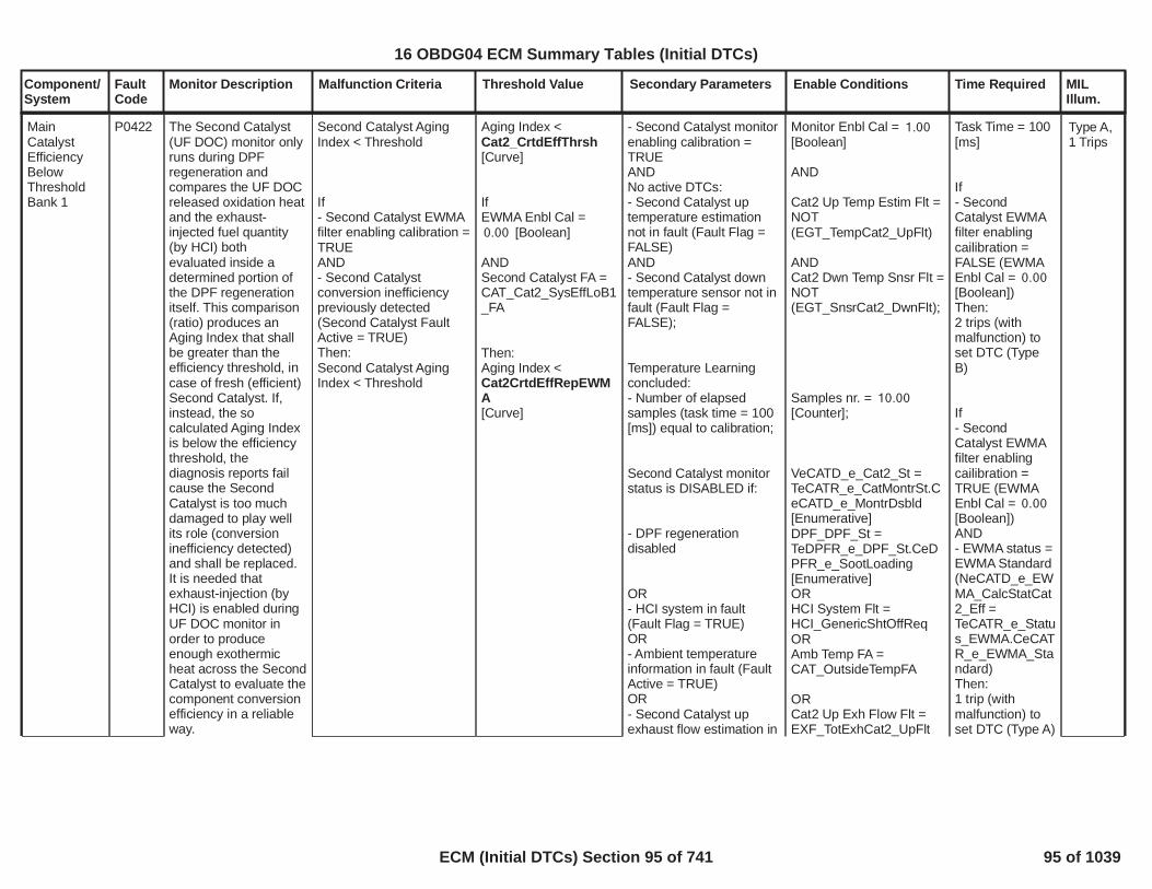
Component/System
FaultCode
Monitor Description Malfunction Criteria Threshold Value Secondary Parameters Enable Conditions Time Required MILIllum.
MainCatalystEfficiencyBelowThresholdBank 1
P0422 The Second Catalyst(UF DOC) monitor onlyruns during DPFregeneration andcompares the UF DOCreleased oxidation heatand the exhaust-injected fuel quantity(by HCI) bothevaluated inside adetermined portion ofthe DPF regenerationitself. This comparison(ratio) produces anAging Index that shallbe greater than theefficiency threshold, incase of fresh (efficient)Second Catalyst. If,instead, the socalculated Aging Indexis below the efficiencythreshold, thediagnosis reports failcause the SecondCatalyst is too muchdamaged to play wellits role (conversioninefficiency detected)and shall be replaced.It is needed thatexhaust-injection (byHCI) is enabled duringUF DOC monitor inorder to produceenough exothermicheat across the SecondCatalyst to evaluate thecomponent conversionefficiency in a reliableway.
Second Catalyst AgingIndex < Threshold
If- Second Catalyst EWMAfilter enabling calibration =TRUEAND- Second Catalystconversion inefficiencypreviously detected(Second Catalyst FaultActive = TRUE)Then:Second Catalyst AgingIndex < Threshold
Aging Index <Cat2_CrtdEffThrsh[Curve]
IfEWMA Enbl Cal =
[Boolean]0.00
ANDSecond Catalyst FA =CAT_Cat2_SysEffLoB1_FA
Then:Aging Index <Cat2CrtdEffRepEWMA[Curve]
- Second Catalyst monitorenabling calibration =TRUEANDNo active DTCs:- Second Catalyst uptemperature estimationnot in fault (Fault Flag =FALSE)AND- Second Catalyst downtemperature sensor not infault (Fault Flag =FALSE);
Temperature Learningconcluded:- Number of elapsedsamples (task time = 100[ms]) equal to calibration;
Second Catalyst monitorstatus is DISABLED if:
- DPF regenerationdisabled
OR- HCI system in fault(Fault Flag = TRUE)OR- Ambient temperatureinformation in fault (FaultActive = TRUE)OR- Second Catalyst upexhaust flow estimation in
Monitor Enbl Cal = 1.00[Boolean]
AND
Cat2 Up Temp Estim Flt =NOT( )EGT_TempCat2_UpFlt
ANDCat2 Dwn Temp Snsr Flt =NOT( );EGT_SnsrCat2_DwnFlt
Samples nr. = 10.00[Counter];
VeCATD_e_Cat2_St =TeCATR_e_CatMontrSt.CeCATD_e_MontrDsbld[Enumerative]
=DPF_DPF_StTeDPFR_e_DPF_St.CeDPFR_e_SootLoading[Enumerative]ORHCI System Flt =HCI_GenericShtOffReqORAmb Temp FA =CAT_OutsideTempFA
ORCat2 Up Exh Flow Flt =EXF_TotExhCat2_UpFlt
Task Time = 100[ms]
If- SecondCatalyst EWMAfilter enablingcailibration =FALSE (EWMAEnbl Cal = 0.00[Boolean])Then:2 trips (withmalfunction) toset DTC (TypeB)
If- SecondCatalyst EWMAfilter enablingcailibration =TRUE (EWMAEnbl Cal = 0.00[Boolean])AND- EWMA status =EWMA Standard(NeCATD_e_EWMA_CalcStatCat2_Eff =TeCATR_e_Status_EWMA.CeCATR_e_EWMA_Standard)Then:1 trip (withmalfunction) toset DTC (Type A)
Type A,1 Trips
16 OBDG04 ECM Summary Tables (Initial DTCs)
ECM (Initial DTCs) Section 95 of 741 95 of 1039
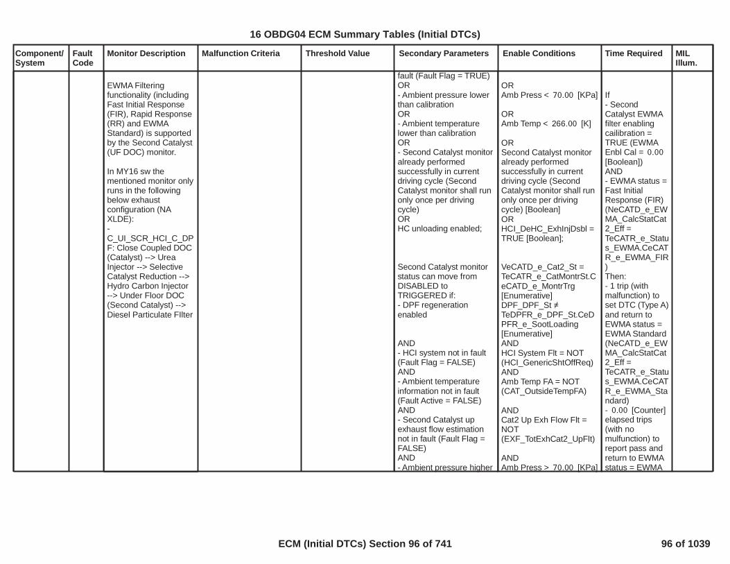
Component/System
FaultCode
Monitor Description Malfunction Criteria Threshold Value Secondary Parameters Enable Conditions Time Required MILIllum.
EWMA Filteringfunctionality (includingFast Initial Response(FIR), Rapid Response(RR) and EWMAStandard) is supportedby the Second Catalyst(UF DOC) monitor.
In MY16 sw thementioned monitor onlyruns in the followingbelow exhaustconfiguration (NAXLDE):-C_UI_SCR_HCI_C_DPF: Close Coupled DOC(Catalyst) --> UreaInjector --> SelectiveCatalyst Reduction -->Hydro Carbon Injector--> Under Floor DOC(Second Catalyst) -->Diesel Particulate FIlter
fault (Fault Flag = TRUE)OR- Ambient pressure lowerthan calibrationOR- Ambient temperaturelower than calibrationOR- Second Catalyst monitoralready performedsuccessfully in currentdriving cycle (SecondCatalyst monitor shall runonly once per drivingcycle)ORHC unloading enabled;
Second Catalyst monitorstatus can move fromDISABLED toTRIGGERED if:- DPF regenerationenabled
AND- HCI system not in fault(Fault Flag = FALSE)AND- Ambient temperatureinformation not in fault(Fault Active = FALSE)AND- Second Catalyst upexhaust flow estimationnot in fault (Fault Flag =FALSE)AND- Ambient pressure higher
ORAmb Press < [KPa]70.00
ORAmb Temp < [K]266.00
ORSecond Catalyst monitoralready performedsuccessfully in currentdriving cycle (SecondCatalyst monitor shall runonly once per drivingcycle) [Boolean]OR
=HCI_DeHC_ExhInjDsblTRUE [Boolean];
VeCATD_e_Cat2_St =TeCATR_e_CatMontrSt.CeCATD_e_MontrTrg[Enumerative]DPF_DPF_StTeDPFR_e_DPF_St.CeDPFR_e_SootLoading[Enumerative]ANDHCI System Flt = NOT( )HCI_GenericShtOffReqANDAmb Temp FA = NOT( )CAT_OutsideTempFA
ANDCat2 Up Exh Flow Flt =NOT( )EXF_TotExhCat2_UpFlt
ANDAmb Press > [KPa]70.00
If- SecondCatalyst EWMAfilter enablingcailibration =TRUE (EWMAEnbl Cal = 0.00[Boolean])AND- EWMA status =Fast InitialResponse (FIR)(NeCATD_e_EWMA_CalcStatCat2_Eff =TeCATR_e_Status_EWMA.CeCATR_e_EWMA_FIR)Then:- 1 trip (withmalfunction) toset DTC (Type A)and return toEWMA status =EWMA Standard(NeCATD_e_EWMA_CalcStatCat2_Eff =TeCATR_e_Status_EWMA.CeCATR_e_EWMA_Standard)- [Counter]0.00elapsed trips(with nomulfunction) toreport pass andreturn to EWMAstatus = EWMA
16 OBDG04 ECM Summary Tables (Initial DTCs)
ECM (Initial DTCs) Section 96 of 741 96 of 1039

Component/System
FaultCode
Monitor Description Malfunction Criteria Threshold Value Secondary Parameters Enable Conditions Time Required MILIllum.
than calibrationAND- Ambient temperaturehigher than calibrationAND- Second Catalyst monitornot yet performedsuccessfully in currentdriving cycle (SecondCatalyst monitor shall runonly once per drivingcycle)AND- IfDPF regeneration hasbeen interrupted inprevious driving cycle orin current driving cycleThen:Engine coolanttemperature lower thancalibrationAND- Second Catalyst upexhaust temperature (byestimation) lower thancalibration;
Second Catalyst monitorstatus can move fromTRIGGERED toENABLED (oxidation heatrelease integrator andexhaust injected fuel (byHCI) integrator are bothenabled) if:- DPF regenerationenabled
AND
ANDAmb Temp > [K]266.00
ANDSecond Catalyst monitornot yet performedsuccessfully in currentdriving cycle (SecondCatalyst monitor shall runonly once per drivingcycle) [Boolean]ANDIfInterrupted DPFregeneration counter > 0[Counter]
Then:Eng Cool Temp < 255.99[°C]
ANDCat2 Up Temp Estim <
[K];1,500.00
VeCATD_e_Cat2_St =TeCATR_e_CatMontrSt.CeCATD_e_MontrEnbl[Enumerative]
DPF_DPF_StTeDPFR_e_DPF_St.CeDPFR_e_SootLoading[Enumerative]AND
Standard(NeCATD_e_EWMA_CalcStatCat2_Eff =TeCATR_e_Status_EWMA.CeCATR_e_EWMA_Standard)
If- SecondCatalyst EWMAfilter enablingcailibration =TRUE (EWMAEnbl Cal = 0.00[Boolean])AND- EWMA status =Rapid Response(RR)(NeCATD_e_EWMA_CalcStatCat2_Eff =TeCATR_e_Status_EWMA.CeCATR_e_EWMA_RR)Then:- 1 trip (withmalfunction) toset DTC (Type A)and return toEWMA status =EWMA Standard(NeCATD_e_EWMA_CalcStatCat2_Eff =TeCATR_e_Status_EWMA.CeCATR_e_EWMA_Sta
16 OBDG04 ECM Summary Tables (Initial DTCs)
ECM (Initial DTCs) Section 97 of 741 97 of 1039

Component/System
FaultCode
Monitor Description Malfunction Criteria Threshold Value Secondary Parameters Enable Conditions Time Required MILIllum.
- HCI system not in fault(Fault Flag = FALSE)AND- Ambient temperatureinformation not in fault(Fault Active = FALSE)AND- Second Catalyst upexhaust flow estimationnot in fault (Fault Flag =FALSE)AND- Ambient pressure higherthan calibrationAND- Ambient temperaturehigher than calibrationAND- Second Catalyst monitornot yet performedsuccessfully in currentdriving cycle (SecondCatalyst monitor shall runonly once per drivingcycle)AND- Second Catalyst upexhaust temperature (byestimation) higher thancalibrationAND- Exhaust injection (byHCI) enabledAND- Second Catalyst upexhaust flow estimationhigher than calibrationAND- Exhaust injection fuelquantity (by HCI) higherthan calibration;
HCI System Flt = NOT( )HCI_GenericShtOffReqANDAmb Temp FA = NOT( )CAT_OutsideTempFA
ANDCat2 Up Exh Flow Flt =NOT( )EXF_TotExhCat2_UpFlt
ANDAmb Press > [KPa]70.00
ANDAmb Temp > [K]266.00
ANDSecond Catalyst monitornot yet performedsuccessfully in currentdriving cycle (SecondCatalyst monitor shall runonly once per drivingcycle) [Boolean]ANDCat2 Up Temp Estim >
[K]0.00
AND=HCI_InjReleaseSt
TRUE [Boolean]ANDCat2 Up Exh Flow > 0.00[g/s]
ANDExh Inj Fuel Qnty (by HCI)> [g];0.00
ndard)- 1 trip (with nomulfunction) toreport pass- [Counter]0.00elapsed trips(with nomulfunction) toreport pass andreturn to EWMAstatus = EWMAStandard(NeCATD_e_EWMA_CalcStatCat2_Eff =TeCATR_e_Status_EWMA.CeCATR_e_EWMA_Standard)
16 OBDG04 ECM Summary Tables (Initial DTCs)
ECM (Initial DTCs) Section 98 of 741 98 of 1039

Component/System
FaultCode
Monitor Description Malfunction Criteria Threshold Value Secondary Parameters Enable Conditions Time Required MILIllum.
Oxidation heat releaseintegrator and exhaustinjected fuel (by HCI)integrator are both frozenif:- Engine not runningOR- Second Catalyst upexhaust flow estimationlower than calibrationOR- Exhaust injection fuelquantity (by HCI) lowerthan calibration;
Second Catalyst monitorstatus can move fromENABLED (oxidation heatrelease integrator andexhaust injected fuel (byHCI) integrator are bothenabled) to DONE(integrators are stoppedand the ratio between thetotal integrated oxidationheat and the totalintegrated injected fuel isperformed with theconsequent creation ofthe Second CatalystAging Index to becompared with the FaultThreshold --> Diagnostictest evaluation trigger) if:- DPF regenerationenabled
AND- HCI system not in fault(Fault Flag = FALSE)
ORCat2 Up Exh Flow < 0.00[g/s]
ORExh Inj Fuel Qnty (by HCI)< [g];0.00
VeCATD_e_Cat2_St =TeCATR_e_CatMontrSt.CeCATD_e_MontrDone[Enumerative]
DPF_DPF_StTeDPFR_e_DPF_St.CeDPFR_e_SootLoading[Enumerative]ANDHCI System Flt = NOT( )HCI_GenericShtOffReq
16 OBDG04 ECM Summary Tables (Initial DTCs)
ECM (Initial DTCs) Section 99 of 741 99 of 1039

Component/System
FaultCode
Monitor Description Malfunction Criteria Threshold Value Secondary Parameters Enable Conditions Time Required MILIllum.
AND- Ambient temperatureinformation not in fault(Fault Active = FALSE)AND- Second Catalyst upexhaust flow estimationnot in fault (Fault Flag =FALSE)AND- Ambient pressure higherthan calibrationAND- Ambient temperaturehigher than calibrationAND- Second Catalyst monitornot yet performedsuccessfully in currentdriving cycle (SecondCatalyst monitor shall runonly once per drivingcycle)AND- Integrated exhaustinjected fuel quantity (byHCI) higher than curve.
ANDAmb Temp FA = NOT( )CAT_OutsideTempFA
ANDCat2 Up Exh Flow Flt =NOT( )EXF_TotExhCat2_UpFlt
ANDAmb Press > [KPa]70.00
ANDAmb Temp > [K]266.00
ANDSecond Catalyst monitornot yet performedsuccessfully in currentdriving cycle (SecondCatalyst monitor shall runonly once per drivingcycle) [Boolean]ANDIntgr Exh Inj Fuel Qnty (byHCI) >
[g].Cat2_CrtdMaxFuel
16 OBDG04 ECM Summary Tables (Initial DTCs)
ECM (Initial DTCs) Section 100 of 741 100 of 1039

Component/System
FaultCode
Monitor Description Malfunction Criteria Threshold Value Secondary Parameters Enable Conditions Time Required MILIllum.
Fuel LevelSensor 1Performance
(For use onvehicles witha single fueltank)
P0461 This DTC will detect afuel sender stuck inrange in the primaryfuel tank.
Delta fuel volume changeover liters of fuel38.2consumed by the engine.
< liters3 Engine Running
No active DTCs: VehicleSpeedSensor_FA
250 ms / sample Type B,2 Trips
102
16 OBDG04 ECM Summary Tables (Initial DTCs)
ECM (Initial DTCs) Section 101 of 741 101 of 1039

Component/System
FaultCode
Monitor Description Malfunction Criteria Threshold Value Secondary Parameters Enable Conditions Time Required MILIllum.
Fuel LevelSensor 1Circuit LowVoltage
P0462 This DTC will detect afuel sender stuck out ofrange low in theprimary fuel tank.
Fuel level Sender % of 5Vrange < %10
failures out100of samples125
100 ms / sample
Type B,2 Trips
103
16 OBDG04 ECM Summary Tables (Initial DTCs)
ECM (Initial DTCs) Section 102 of 741 102 of 1039

Component/System
FaultCode
Monitor Description Malfunction Criteria Threshold Value Secondary Parameters Enable Conditions Time Required MILIllum.
Fuel LevelSensor 1Circuit HighVoltage
P0463 This DTC will detect afuel sender stuck out ofrange high in theprimary fuel tank.
Fuel level Sender % of 5Vrange > %60
failures out100of samples125
100 ms / sample
Type B,2 Trips
104
16 OBDG04 ECM Summary Tables (Initial DTCs)
ECM (Initial DTCs) Section 103 of 741 103 of 1039

Component/System
FaultCode
Monitor Description Malfunction Criteria Threshold Value Secondary Parameters Enable Conditions Time Required MILIllum.
Cooling Fan1 RelayControlCircuit Open(ODM) (Notused onEREV)
P0480 Diagnoses the coolingfan 1 relay control lowside driver circuit forcircuit faults
Voltage low during driveroff state (indicates opencircuit)
Open Circuit: 200 K impedance
between signal andcontroller ground
Powertrain Relay Voltage Voltage volts11.00 failures out of50samples63
100 ms / sample
Type B,2 Trips
Note: Incertaincontrollers P0691may alsoset (Fan1 ShorttoGround).
105
16 OBDG04 ECM Summary Tables (Initial DTCs)
ECM (Initial DTCs) Section 104 of 741 104 of 1039

Component/System
FaultCode
Monitor Description Malfunction Criteria Threshold Value Secondary Parameters Enable Conditions Time Required MILIllum.
Cooling FanSystemPerformance
P0483 Detects inability tocontrol fan speed todesired RPM
1. Weighted filtereddifference between actualfan speed andcommanded fan speed[Min]
OR
2. Weighted filtereddifference between actualfan speed andcommanded fan speed[Max]
1. <= RPM-500.00
OR
2. >= RPM500.00
1. System PerformancetestAND2. Intake Air TempAND3. System VoltageAND4. Commanded Fan SpdAND5. Fan Drive Spd [Min]AND6. Fan Drive Spd [Max]AND7. Engine Coolant TempAND8. Fan Drive Spd Rate ofChangeAND9. Outside Air TempAND10. Barometric PressureAND11. Fan Spd WeightFactor calculation
Calculated product of[FactorA]*[FactorB]*
[FactorC]*[FactorD]where
FactorA: Input speedstability basis[See Supporting Table A]
FactorB: Input Speedbasis[See Supporting Table B]
FactorC: EngineCoolant Temp basis[See Supporting Table C]
FactorD: Intake AirTemp basis[See Supporting Table D]
1. = 1.00AND2. degC-7.00AND3. >= Volts11.00AND4. >= %15.00AND5. >= RPM200.00AND6. <= RPM5,320.00AND7. degC69.00AND8. < RPM/sec2,000.00AND9. >= degC-7.00AND10. > kPa74.00AND11. > 0.60
Fail condtionpresent >=
;600.00
100 ms / sample
Type B,2 Trips
106
16 OBDG04 ECM Summary Tables (Initial DTCs)
ECM (Initial DTCs) Section 105 of 741 105 of 1039

Component/System
FaultCode
Monitor Description Malfunction Criteria Threshold Value Secondary Parameters Enable Conditions Time Required MILIllum.
Cooling FanSpeed High
P0495 Diagnoses the enginedriven cooling fanduring OFF state
Fan speed is too highwhen fan command to theoff state
Fan speed > 1,500RPM
Test enabled = 1.00
Fluid in fan clutch ispumped out
failures out800of samples1,000
100 ms / sample
Type B,2 Trips
107
16 OBDG04 ECM Summary Tables (Initial DTCs)
ECM (Initial DTCs) Section 106 of 741 106 of 1039

Component/System
FaultCode
Monitor Description Malfunction Criteria Threshold Value Secondary Parameters Enable Conditions Time Required MILIllum.
Low EngineSpeed IdleSystem
P0506 This DTC willdetermine if a low idleexists
Filtered Engine SpeedError
filter coefficient
> rpm75.00
0.00175
Baro
Coolant Temp
Engine run time
Ignition voltage
Time since gear change
Time since a TCC modechange
IAT
Vehicle speed
Commanded RPM delta
Idle time
For manualtransmissions:Clutch Pedal PositionorClutch Pedal Position
> kPa70
>KeSPDD_T_EnblECT_Min ( °C) and <60KfECTI_T_EngCoolHotHiThresh ( °C)120Must verifyKfECTI_T_EngCoolHotLoThresh ( ) is less than118KfECTI_T_EngCoolHotHiThresh ( )120
sec60
volts 32 11
sec3
> sec3
> °C-20
mph1.24
rpm25
> sec5
> pct12.00
< pct75.00
Diagnostic runsin every 12.5 msloop
Diagnosticreports pass orfail in 10seconds once allenableconditions aremet
Type B,2 Trips
108
16 OBDG04 ECM Summary Tables (Initial DTCs)
ECM (Initial DTCs) Section 107 of 741 107 of 1039

Component/System
FaultCode
Monitor Description Malfunction Criteria Threshold Value Secondary Parameters Enable Conditions Time Required MILIllum.
No active DTCs
PTO not active
Transfer Case not in 4WDLowState
Off-vehicle device control(service bay control) mustnot be active.
following conditions notTRUE:(VeTESR_e_EngSpdReqIntvType =CeTESR_e_EngSpdMinLimit ANDVeTESR_e_EngSpdReqRespType =CeTESR_e_NoSuggestion)
Clutch is not depressed
TC_BoostPresSnsrFAECT_Sensor_FAEnginePowerLimitedEGRValveCircuit_FAEGRValvePerformance_FAIAT_SensorCircuitFAEvapFlowDuringNonPurge_FAFuelTrimSystemB1_FAFuelTrimSystemB2_FAFuelInjectorCircuit_FAMAF_SensorFAEngineMisfireDetected_FAIgnitionOutputDriver_FA
109
16 OBDG04 ECM Summary Tables (Initial DTCs)
ECM (Initial DTCs) Section 108 of 741 108 of 1039

Component/System
FaultCode
Monitor Description Malfunction Criteria Threshold Value Secondary Parameters Enable Conditions Time Required MILIllum.
All of the above metfor Idle time
TPS_FATPS_Performance_FAVehicleSpeedSensor_FAFuelLevelDataFaultLowFuelConditionDiagnosticClutch Sensor FAAmbPresDfltdStatusP2771
> sec5
The diagnostic does notrun during autostop asengine is shutdown duringthat time (occurs in ahybrid or 12v start stopvehicle)
110
16 OBDG04 ECM Summary Tables (Initial DTCs)
ECM (Initial DTCs) Section 109 of 741 109 of 1039

Component/System
FaultCode
Monitor Description Malfunction Criteria Threshold Value Secondary Parameters Enable Conditions Time Required MILIllum.
High EngineSpeed IdleSystem
P0507 This DTC willdetermine if a high idleexists
Filtered Engine SpeedError
filter coefficient
< rpm-150.00
0.00175
Baro
Coolant Temp
Engine run time
Ignition voltage
Time since gear change
Time since a TCC modechange
IAT
Vehicle speed
Commanded RPM delta
For manualtransmissions:Clutch Pedal PositionorClutch Pedal Position
> kPa70
>KeSPDD_T_EnblECT_Min ( °C) and <60KfECTI_T_EngCoolHotHiThresh ( °C)120Must verifyKfECTI_T_EngCoolHotLoThresh ( ) is less than118KfECTI_T_EngCoolHotHiThresh ( )120
sec60
volts 32 11
sec3
> sec3
> °C-20
mph1.24
rpm25
> pct12.00
< pct75.00
Diagnostic runsin every 12.5 msloop
Diagnosticreports pass orfail in 10seconds once allenableconditions aremet
Type B,2 Trips
111
16 OBDG04 ECM Summary Tables (Initial DTCs)
ECM (Initial DTCs) Section 110 of 741 110 of 1039

Component/System
FaultCode
Monitor Description Malfunction Criteria Threshold Value Secondary Parameters Enable Conditions Time Required MILIllum.
No active DTCs
PTO not active
Transfer Case not in 4WDLowState
Off-vehicle device control(service bay control) mustnot be active.
following conditions notTRUE:(VeTESR_e_EngSpdReqIntvType =CeTESR_e_EngSpdMinLimit ANDVeTESR_e_EngSpdReqRespType =CeTESR_e_NoSuggestion)
Clutch is not depressed
TC_BoostPresSnsrFAECT_Sensor_FAEnginePowerLimitedEGRValveCircuit_FAEGRValvePerformance_FAIAT_SensorCircuitFAEvapFlowDuringNonPurge_FAFuelTrimSystemB1_FAFuelTrimSystemB2_FAFuelInjectorCircuit_FAMAF_SensorFAEngineMisfireDetected_FAIgnitionOutputDriver_FATPS_FATPS_Performance_FAVehicleSpeedSensor_FA
112
16 OBDG04 ECM Summary Tables (Initial DTCs)
ECM (Initial DTCs) Section 111 of 741 111 of 1039

Component/System
FaultCode
Monitor Description Malfunction Criteria Threshold Value Secondary Parameters Enable Conditions Time Required MILIllum.
All of the above metfor Idle time
FuelLevelDataFaultLowFuelConditionDiagnosticClutch SensorFAAmbPresDfltdStatusP2771
> sec5
The diagnostic does notrun during autostop asengine is shutdown duringthat time (occurs in ahybrid or 12v start stopvehicle)
113
16 OBDG04 ECM Summary Tables (Initial DTCs)
ECM (Initial DTCs) Section 112 of 741 112 of 1039

Component/System
FaultCode
Monitor Description Malfunction Criteria Threshold Value Secondary Parameters Enable Conditions Time Required MILIllum.
Engine OilPressure(EOP)SensorCircuit LowVoltage
P0522 Determines if theEngine Oil Pressure(EOP) Sensor circuitvoltage is too low
(Engine Oil PressureSensor Circuit Voltage) ÷5 Volts) *100 < percent5.00
Engine Speed EnableEngine Speed Disable
Oil Pressure Sensor InUse
Diagnostic Status
> rpm400< rpm350
Yes
Enabled
failures out800of 1,000samples
Performed every6.25 msec
Type C,No SVS
114
16 OBDG04 ECM Summary Tables (Initial DTCs)
ECM (Initial DTCs) Section 113 of 741 113 of 1039

Component/System
FaultCode
Monitor Description Malfunction Criteria Threshold Value Secondary Parameters Enable Conditions Time Required MILIllum.
Engine OilPressure(EOP)SensorCircuit HighVoltage
P0523 Determines if theEngine Oil Pressure(EOP) Sensor circuitvoltage is too high
(Engine Oil PressureSensor Circuit Voltage) ÷5 Volts) *100
> percent95.00Oil Pressure Sensor InUse
Diagnostic Status
Yes
Enabled
failures out800of 1,000samplesPerformed every6.25 msec
Type C,No SVS
115
16 OBDG04 ECM Summary Tables (Initial DTCs)
ECM (Initial DTCs) Section 114 of 741 114 of 1039

Component/System
FaultCode
Monitor Description Malfunction Criteria Threshold Value Secondary Parameters Enable Conditions Time Required MILIllum.
Cooling FanSpeedSensorCircuit
P0526 Diagnoses the enginedriven cooling fanspeed sensor
Measured fan speed isless than a RPMthreshold
Measured fan speed<= RPM4.00
Run/Crank Voltage
Fan duty cycle
Voltage volts11.00
% for time 36.00 2.00seconds
failures out900of samples1,200
100 ms / sample
Type B,2 Trips
116
16 OBDG04 ECM Summary Tables (Initial DTCs)
ECM (Initial DTCs) Section 115 of 741 115 of 1039

Component/System
FaultCode
Monitor Description Malfunction Criteria Threshold Value Secondary Parameters Enable Conditions Time Required MILIllum.
Engaged Test
Primary EnableConditons:
Compressor Type =Electric Driven
Diagnostic Status
Engaged Test Status
Enable with Key Off
No active DTC's
Electronic Varaible
Disabled
Disabled
Disabled
Fault bundles:ACHighSidePressSnsrCktFAACFailedOnSDACThrmlRefrigSpdVldACCMLostComm
AirConditioningHigh SidePressureSensor(HSPS)SensorPerformance
P0531 Determines if the AirConditioning High SidePressure Sensor circuitvoltage is stuck orbiased in range
Type X,No MIL
To fail a currently passingEngaged test:
The filtered, weightedratio between measuredDelta and predicted delta(a function of ambienttemp, coolant temp,vehicle speed, and fanspeed.):
Measured Test DeltaPressure ÷Predicted EngagedTest Filtered WeightedPressure) * first orderfilter coefficient <0.0996
Predicted EngagedTest Filtered WeightedPressure =(P0531_Coolant_Weighting_Factor*P0531_FanSpeed_Weighting_Factor*
*P0531_Delta_Predicted_ Pressure
)P0531_Delta_Predicted_Quality_Factorwith a 1st order filtercoefficient =
Use First Order Filter =FALSE
Quality or weighting factorvalues less than “1”indicate that we don’thave 4sigma/2sigmarobustness in that region.The quality of the data isdetermined via statisticalanalysis of Variance data.Regions where diagnosisis possible have a qualityor weighting factor values:
0.10
Compressor Speed >RPM150
P0531_Delta_Predicted_Quality_Factor> 0.0
andP0531_Coolant_Weighting_Factor> - AND <0.0 4.0
andP0531_FanSpeed_Weighting_Factor> - AND <0.0 4.0
Performed every100 msec
117
16 OBDG04 ECM Summary Tables (Initial DTCs)
ECM (Initial DTCs) Section 116 of 741 116 of 1039

Component/System
FaultCode
Monitor Description Malfunction Criteria Threshold Value Secondary Parameters Enable Conditions Time Required MILIllum.
(P0531 Engage TestDetails on SupportingTables Tab:P0531_Coolant_Weighting_FactorP0531_FanSpeed_Weighting_FactorP0531_Delta_Predicted_ Pressure
)P0531_Delta_Predicted_Quality_Factor
Fast Initial Response(FIR):
FIR will trigger when anNVM reset or code clearoccurs.Once triggered, thefiltered ratio is reset toInitial response test ratio:FIR Test Ratio = 1.00with an initial responsefirst order filter:FIR Test Filter = 0.00
Rapid Step Response(RSR):
RSR will trigger if the ratioresult from the last test is< 0.40ANDthe delta from the lastfiltered ratio by > 0.05
Once triggered, the RSRfiltered ratio is reset to:RSR Test Ratio = 1.00with an rapid stepresponse first order filter:RSR Test Filter = 0.00
FIR tests must0complete beforethe diagnosticcan report.
RSR tests0must completebefore thediagnostic canreport.
To pass a currently failingEngaged test:
The filtered, weightedratio between measureddelta and predicted delta(a function of ambienttemp, coolant temp,
Measured Test DeltaPressure /Predicted EngagedTest: Filtered WeightedPressure) * first order
Use First Order Filter =FALSE
Quality or weighting factorvalues less than “1”indicate that we don’t
Compressor Speed >RPM150
P0531_Delta_Predicted_Quality_Factor> 0.0
Performed every100 msec
# of TestSamples = 100
118
16 OBDG04 ECM Summary Tables (Initial DTCs)
ECM (Initial DTCs) Section 117 of 741 117 of 1039

Component/System
FaultCode
Monitor Description Malfunction Criteria Threshold Value Secondary Parameters Enable Conditions Time Required MILIllum.
vehicle speed and fanspeed.):
filter coefficient =>0.0996
Predicted EngagedTest Filtered WeightedPressure =(P0531_Coolant_Weighting_Factor*P0531_FanSpeed_Weighting_Factor*
*P0531_Delta_Predicted_ Pressure
)P0531_Delta_Predicted_Quality_Factorwith a first order filtercoefficient =
(P0531 Engage TestDetails on SupportingTables Tab:P0531_Coolant_Weighting_FactorP0531_FanSpeed_Weighting_FactorP0531_Delta_Predicted_ PressureP0531_Delta_Predicted_Quality_Factor)
have 4sigma/2sigmarobustness in that region.The quality of the data isdetermined via statisticalanalysis of Variance data.Regions where diagnosisis possible have a qualityor weighting factor values:
0.10
Fast Initial Response(FIR):
FIR will trigger when anNVM reset or code clearoccurs.Once triggered, thefiltered ratio is reset toInitial response test ratio:FIR Test Ratio = 1.00with an initial responsefirst order filter:FIR Test Filter = 0.00
Rapid Step Response(RSR):
RSR will trigger if the ratioresult from the last test is< 0.40AND
andP0531_Coolant_Weighting_Factor> - AND <0.0 4.0
andP0531_FanSpeed_Weighting_Factor> - AND <0.0 4.0
FIR tests must0complete beforethe diagnosticcan report.
RSR tests0must completebefore thediagnostic canreport.
119
16 OBDG04 ECM Summary Tables (Initial DTCs)
ECM (Initial DTCs) Section 118 of 741 118 of 1039

Component/System
FaultCode
Monitor Description Malfunction Criteria Threshold Value Secondary Parameters Enable Conditions Time Required MILIllum.
the delta from the lastfiltered ratio by > 0.05
Once triggered, the RSRfiltered ratio is reset to:RSR Test Ratio = 1.00with an rapid stepresponse first order filter:RSR Test Filter = 0.00
120
16 OBDG04 ECM Summary Tables (Initial DTCs)
ECM (Initial DTCs) Section 119 of 741 119 of 1039

Component/System
FaultCode
Monitor Description Malfunction Criteria Threshold Value Secondary Parameters Enable Conditions Time Required MILIllum.
AirConditioningHigh SidePressureSensor(HSPS)Circuit LowVoltage
P0532 Determines if the AirConditioning High SidePressure Sensor circuitvoltage is too low
(AC High Side PressureSensor Circuit Voltage) ÷5 Volts) *100
< percent2AC HSP Sensor Present
Diagnostic Status
Yes
Enabled
80failures out of100samples
Performed every25 msec
Type C,No SVS
121
16 OBDG04 ECM Summary Tables (Initial DTCs)
ECM (Initial DTCs) Section 120 of 741 120 of 1039

Component/System
FaultCode
Monitor Description Malfunction Criteria Threshold Value Secondary Parameters Enable Conditions Time Required MILIllum.
AirConditioningHigh SidePressureSensor(HSPS)Circuit HighVoltage
P0533 Determines if the AirConditioning High SidePressure Sensor circuitvoltage is too high
(AC High Side PressureSensor Circuit Voltage) ÷5 Volts) *100
> percent98AC HSP Sensor Present
Diagnostic Status
Yes
Enabled
failures out80of samples100
Performed every25 msec
Type C,No SVS
122
16 OBDG04 ECM Summary Tables (Initial DTCs)
ECM (Initial DTCs) Section 121 of 741 121 of 1039

Component/System
FaultCode
Monitor Description Malfunction Criteria Threshold Value Secondary Parameters Enable Conditions Time Required MILIllum.
SystemVoltage Low
P0562 Diagnoses the 12Vbattery system low
System voltage low Battery voltage <=9.00
System voltage low diagenable = TRUE
Run Crank voltage
Engine speed >=
1.00
Voltage volts6.00
400.00
failures out400of samples500
12.5 ms / sample
Type C,No SVS
123
16 OBDG04 ECM Summary Tables (Initial DTCs)
ECM (Initial DTCs) Section 122 of 741 122 of 1039

Component/System
FaultCode
Monitor Description Malfunction Criteria Threshold Value Secondary Parameters Enable Conditions Time Required MILIllum.
SystemVoltage High
P0563 Diagnoses the 12Vbattery system high
System voltage high Battery voltage >=18.00
System voltage high diagenable = TRUE
Run Crank voltage
1.00
Voltage volts6.00
failures out400of samples500
12.5 ms / sample
Type C,No SVS
124
16 OBDG04 ECM Summary Tables (Initial DTCs)
ECM (Initial DTCs) Section 123 of 741 123 of 1039

Component/System
FaultCode
Monitor Description Malfunction Criteria Threshold Value Secondary Parameters Enable Conditions Time Required MILIllum.
CruiseControlMutil-FunctonSwitchCircuit
P0564 Detect when cruisecontrol multi-functionswitch circuit (analog)voltage is in an invalidrange
Cruise Control analogcircuit voltage must be"between ranges" forgreater than a calibratableperiod of time.
The cruise controlanalog voltage A/Dcount ratio isconsiderred to be"between ranges"when the ratio ismeasured in thefollowing ranges:
0.28 -0.31,0.415-0.445,0.585 - 0.6150.78 - 0.81,1.005 - 1.035
CAN cruise switchdiagnostic enable in ECM
1.00 fail continuouslyfor greater than0.500seconds
Type C,No SVS, specialtype C
125
16 OBDG04 ECM Summary Tables (Initial DTCs)
ECM (Initial DTCs) Section 124 of 741 124 of 1039

Component/System
FaultCode
Monitor Description Malfunction Criteria Threshold Value Secondary Parameters Enable Conditions Time Required MILIllum.
CruiseControl OnSwitchCircuit
P0565 Detects a failure of thecruise on/off switch in acontinously appliedstate
Cruise Control On switchremains applied forgreater than a calibratableperiod of time.
fail continuously in theapplied state forgreater than
seconds20.00
CAN cruise switchdiagnostic enable in ECM
1.00 fail continuouslyfor greater than
seconds20.00
Type C,No SVS, specialtype C
126
16 OBDG04 ECM Summary Tables (Initial DTCs)
ECM (Initial DTCs) Section 125 of 741 125 of 1039

Component/System
FaultCode
Monitor Description Malfunction Criteria Threshold Value Secondary Parameters Enable Conditions Time Required MILIllum.
CruiseControlResumeCircuit
P0567 Detects a failure of thecruise resume switch ina continously appliedstate
Cruise Control Resumeswitch remains applied forgreater than a calibratableperiod of time.
fail continuously in theapplied state forgreater than89.000seconds
CAN cruise switchdiagnostic enable in ECM
1.00 fail continuouslyfor greater than89.000seconds
Type C,No SVS, specialtype C
127
16 OBDG04 ECM Summary Tables (Initial DTCs)
ECM (Initial DTCs) Section 126 of 741 126 of 1039

Component/System
FaultCode
Monitor Description Malfunction Criteria Threshold Value Secondary Parameters Enable Conditions Time Required MILIllum.
CruiseControl SetCircuit
P0568 Detects a failure of thecruise set switch in acontinously appliedstate
Cruise Control Set switchremains applied forgreater than a calibratableperiod of time.
fail continuously in theapplied state forgreater than89.000seconds
CAN cruise switchdiagnostic enable in ECM
1.00 fail continuouslyfor greater than89.000seconds
Type C,No SVS, specialtype C
128
16 OBDG04 ECM Summary Tables (Initial DTCs)
ECM (Initial DTCs) Section 127 of 741 127 of 1039

Component/System
FaultCode
Monitor Description Malfunction Criteria Threshold Value Secondary Parameters Enable Conditions Time Required MILIllum.
CruiseControlCancelSwitchCircuit
P056C Cruise Control Cancelswitch remains applied forgreater than a calibratableperiod of time.
fail continously in theapplied state forgreater than
seconds20.00
CAN cruise switchdiagnostic enable in ECM
1.00 fail continuouslyfor greater than
seconds20.00
Type C,No SVS, specialtype C
129
16 OBDG04 ECM Summary Tables (Initial DTCs)
ECM (Initial DTCs) Section 128 of 741 128 of 1039

Component/System
FaultCode
Monitor Description Malfunction Criteria Threshold Value Secondary Parameters Enable Conditions Time Required MILIllum.
CruiseControl InputCircuit
P0575 Determines if cruiseswitch state receivedfrom the BCM is valid.
If x of y rolling count /protection value faultsoccur, disable cruise forduration of fault
Message <> 2'scomplement ofmessage
Message rolllingcount<>previousmessage rolling countvalue plus one
Cruise Control SwitchSerial Data ErrorDiagnostic Enable
Serial communication toBCM
Power ModeEngine Running
1.00
No loss of communication
= RUN= TRUE
failures out10of/ samples16
Performed onevery receivedmessage
rolling count10failures out of/ samples16
Performed onevery receivedmessagw
Type C,No SVS, specialtype C
130
16 OBDG04 ECM Summary Tables (Initial DTCs)
ECM (Initial DTCs) Section 129 of 741 129 of 1039

Component/System
FaultCode
Monitor Description Malfunction Criteria Threshold Value Secondary Parameters Enable Conditions Time Required MILIllum.
. Brake Pedal PositionSensor Circuit Range /Performance DiagnosticEnable
1.00
ignition voltage > 10.00
Brake PedalPositionSensorCircuitRange/Performance
P057B This diagnosticmonitors the BrakePedal Position Sensorfor a stuck in rangefailure
MIL:Type A,1 Trips
Calculated EWMA valuemust be greater thancalibratable theshold aftercalibratable number oftests have completed toreport a "test passed" forP057B
EWMA value looked upin supporting tableP057BKtBRKI_K_FastTestPointWeightP057B as a function ofcalculated brake pedalposition delta EWMAvalue is > 0.80
calculated brake pedalposition delta samplecounter >
for fast test50.00
OR
calculated brake pedalposition delta samplecounter > for1,000.00slow test
calculated brake pedalposition delta > 8.00
OR (for slow test)
shift lever has been inpark once this key cycle
vehicle speed >= 5.00
accelerator pedal position< 5.00
total number ofEWMA tests >20.00
Calculated EWMA Valuemust be less thancalibratable thresholdafter calibratable numberof tests have completed toreport a "test failed" forP057B. This test runsonce per key cycle
EWMA value looked upin supporting tableP057BKtBRKI_K_CmpltTestPointWeightP057Bas a function ofcalculated brake pedalposition deltaEWMA value is lessthatn 0.40
no DTC's active (P057C,P057D)
shift lever has been inpark once this key cycle
vehicle speed >= 5.00
accelerator pedal position< 5.00
total number ofEWMA tests >2.00
131
16 OBDG04 ECM Summary Tables (Initial DTCs)
ECM (Initial DTCs) Section 130 of 741 130 of 1039

Component/System
FaultCode
Monitor Description Malfunction Criteria Threshold Value Secondary Parameters Enable Conditions Time Required MILIllum.
Brake PedalPositionSensorCircuit Low
P057C detects short to groundfor brake pedal positionsensor
If x of y samples areobserved below failurethreshold, default brakepedal position to zeropercent.
5.00 Brake Pedal PositionSensore Low VoltageDiagnostic Enable
1.0020/ 32.00counts
MIL:Type A,1 Trips
132
16 OBDG04 ECM Summary Tables (Initial DTCs)
ECM (Initial DTCs) Section 131 of 741 131 of 1039

Component/System
FaultCode
Monitor Description Malfunction Criteria Threshold Value Secondary Parameters Enable Conditions Time Required MILIllum.
Brake PedalPositionSensorCircuit High
P057D detects open circuit forbrake pedal positionsensor
If x of y samples areobserved above failurethreshold, default brakepedal position to zeropercent and set DTC
95.00 Brake Pedal PositionSensore High VoltageDiagnostic Enable
1.00 /20.00
counts32.00
MIL:Type A,1 Trips
133
16 OBDG04 ECM Summary Tables (Initial DTCs)
ECM (Initial DTCs) Section 132 of 741 132 of 1039

Component/System
FaultCode
Monitor Description Malfunction Criteria Threshold Value Secondary Parameters Enable Conditions Time Required MILIllum.
Brake PedalPositionSensorCircuitIntermittent/Erratic
P057E detects noisy / erraticouput for brake pedalposition sensor
If x of y samples areobserved above failurethreshold, default brakepedal position to zeropercent and set DTC
25.00 Brake Pedal PositionSensor CircuitIntermittent / ErraticDiagnostic Enable
1.00 /10.00
counts16.00
MIL:Type A,1 Trips
134
16 OBDG04 ECM Summary Tables (Initial DTCs)
ECM (Initial DTCs) Section 133 of 741 133 of 1039

Component/System
FaultCode
Monitor Description Malfunction Criteria Threshold Value Secondary Parameters Enable Conditions Time Required MILIllum.
CruiseControlMulti-functionCircuit LowVoltage
P0580 detects short to groundfailure for cruise multi-function switch circuit
Cruise Control analogcircuit voltage must be inan "Open Short ToGround" range for greaterthan a calibratable periodof time.
The cruise controlanalog voltage A/Dcount ratio isconsiderred to be"open short to groundwhen the ratio ismeasured in thefollowing rangs:
0 - 0.185
CAN cruise switchdiagnostic enable in ECM
1.00 fail continuouslyfor greater than2.00seconds
Type C,No SVS, specialtype C
135
16 OBDG04 ECM Summary Tables (Initial DTCs)
ECM (Initial DTCs) Section 134 of 741 134 of 1039

Component/System
FaultCode
Monitor Description Malfunction Criteria Threshold Value Secondary Parameters Enable Conditions Time Required MILIllum.
CruiseControlMulti-functionCircuit HighVoltage
P0581 Cruise Control analogcircuit voltage must be in"Short To Power" rangefor greater than acalibratable period oftime.
The cruise controlanalog voltage A/Dcount ratio isconsidered to be"short to power" whenthe ratio is measuredin the following range:
1.005 - 1.035
CAN cruise switchdiagnostic enable in ECM
1.00 fail continuouslyfor greater than2.00seconds
Type C,No SVS, specialtype C
136
16 OBDG04 ECM Summary Tables (Initial DTCs)
ECM (Initial DTCs) Section 135 of 741 135 of 1039

Component/System
FaultCode
Monitor Description Malfunction Criteria Threshold Value Secondary Parameters Enable Conditions Time Required MILIllum.
The Primary Processor'scalculated checksumdoes not match the storedchecksum value. Coversall software andcalibrations.
1 failure if the fault isdetected during thefirst pass.5failures if the faultoccurs after the firstpass is complete.
Diagnostic runscontinuously inthe background.
ControlModuleRead OnlyMemory(ROM)
P0601 This DTC will be storedif the calibration checksum is incorrect or theflash memory detectsan uncorrectable errorvia the Error CorrectingCode.
Type A,1 Trips
The Primary Processor'sError Correcting Codehardware in the flashmemory detects an error.Covers all software andcalibrations.
254failures detected viaError Correcting Code
Diagnostic runscontinuously viathe flashhardware.
The Primary Processor'scalculated checksumdoes not match the storedchecksum value for aselected subset of thecalibrations.
2 consecutive failuresdetected or5total failures detected.
Diagnostic runscontinuously.Will report adetected faultwithin 200 ms.
The SecondaryProcessor's calculatedchecksum does not matchthe stored checksumvalue. Covers allsoftware and calibrations.
1 failure if the fault isdetected during thefirst pass.
failures if the fault5occurs after the firstpass is complete.
Diagnostic runscontinuously inthe background.
In all cases, the failurecount is cleared whencontroller shuts down
137
16 OBDG04 ECM Summary Tables (Initial DTCs)
ECM (Initial DTCs) Section 136 of 741 136 of 1039

Component/System
FaultCode
Monitor Description Malfunction Criteria Threshold Value Secondary Parameters Enable Conditions Time Required MILIllum.
ControlModule NotProgrammed
P0602 This DTC will be storedif the ECU is a servicepart that has not beenprogrammed.
Service (reflash) controllercalibration present
= 1 none Diagnostic runsat powerup andonce per secondcontinuouslyafter that
Type A,1 Trips
138
16 OBDG04 ECM Summary Tables (Initial DTCs)
ECM (Initial DTCs) Section 137 of 741 137 of 1039

Component/System
FaultCode
Monitor Description Malfunction Criteria Threshold Value Secondary Parameters Enable Conditions Time Required MILIllum.
Static NVM region errordetected duringinitialization
Diagnostic runsat controllerpower up.
ECM LongTermMemoryReset
P0603 This DTC detects aninvalid NVM.
Type A,1 Trips
Perserved NVM regionerror detected duringinitialization
Diagnostic runsat controllerpower up.
ECC ROM fault detectedin NVM Flash region
ECC ROM Error Count > 3
Diagnostic runsat controllerpower up.
Perserved NVM regionerror detected during shutdown.
Diagnostic runsat controllerpower down.
139
16 OBDG04 ECM Summary Tables (Initial DTCs)
ECM (Initial DTCs) Section 138 of 741 138 of 1039

Component/System
FaultCode
Monitor Description Malfunction Criteria Threshold Value Secondary Parameters Enable Conditions Time Required MILIllum.
Indicates that the primaryprocessor is unable tocorrectly read data fromor write data to systemRAM. Detects data readdoes not match datawritten >=
counts254 Will finish firstmemory scanwithin 30seconds at allengineconditions -diagnostic runscontinuously(backgroundloop)
ECM RAMFailure
P0604 Indicates that the ECMhas detected a RAMfault
Type A,1 Trips
Indicates that the primaryprocessor is unable tocorrectly read data fromor write data to cachedRAM. Detects data readdoes not match datawritten >=
counts254 Will finish firstmemory scanwithin 30seconds at allengineconditions -diagnostic runscontinuously(backgroundloop)
Indicates that the primaryprocessor is unable tocorrectly read data fromor write data to TPU RAM.Detects data read doesnot match data written >=
counts5 Will finish firstmemory scanwithin 30seconds at allengineconditions -diagnostic runscontinuously(backgroundloop)
Indicates that the primaryprocessor detects amismatch between thedata and dual data isfound during RAMupdates. Detects amismatch in data and dualdata updates >
s0.45891 When dual storeupdates occur.
140
16 OBDG04 ECM Summary Tables (Initial DTCs)
ECM (Initial DTCs) Section 139 of 741 139 of 1039

Component/System
FaultCode
Monitor Description Malfunction Criteria Threshold Value Secondary Parameters Enable Conditions Time Required MILIllum.
Indicates that the primaryprocessor detects anillegal write attempt toprotected RAM. Numberof illegal writes are >
counts65,534 Diagnostic runscontinuously(backgroundloop)
Indicates that thesecondary processor isunable to correctly readdata from or write data tosystem RAM. Detectsdata read does not matchdata written >=
counts5 Will finish firstmemory scanwithin 30seconds at allengineconditions -diagnostic runscontinuously(backgroundloop)
141
16 OBDG04 ECM Summary Tables (Initial DTCs)
ECM (Initial DTCs) Section 140 of 741 140 of 1039

Component/System
FaultCode
Monitor Description Malfunction Criteria Threshold Value Secondary Parameters Enable Conditions Time Required MILIllum.
Loss or invalid messageof SPI communicationfrom the SecondaryProcessor at initializationdetected by the PrimaryProcessor or loss orinvalid message of SPIcommunication from theSecondary Processorafter a valid message wasreceived by the PrimaryProcessor
Loss or invalidmessage atinitialization detectedor loss or invalidmessage after a validmessage was recieved
Run/Crank voltage >=6.41or Run/Crank voltage >=
,11.00else the failure will bereported for all conditions
In the primaryprocessor,
/ counts159 399intermittent or
counts39continuous;
counts39continuous @initialization.12.5 ms /count inthe ECM mainprocessor
Internal ECMProcessorIntegrityFault
P0606 Indicates that the ECMhas detected aninternal processorintegrity fault
Type A,1 Trips
Loss or invalid messageof SPI communicationfrom the PrimaryProcessor at initializationdetected by theSecondary Processor orloss or invalid message ofSPI communication fromthe Primary Processorafter a valid message wasreceived by theSecondary Processor
Loss or invalidmessage atinitialization detectedor loss or invalidmessage after a validmessage was recieved
In the secondaryprocessor,
/ counts20 200intermittent or
s0.1875continuous;
s0.4750continuous @initialization.12.5 ms /count inthe ECMsecondaryprocessor
Checks for stack over orunderflow in secondaryprocessor by looking forcorruption of knownpattern at stackboundaries. Checksnumber of stack over/under flow since lastpowerup reset >=
5 KeMEMD_b_StackLimitTestEnbl == 1Value ofKeMEMD_b_StackLimitTestEnbl is: .1(If 0, this test is disabled)
variable,depends onlength of time tocorrupt stack
MAIN processor is verifiedby responding to a seedsent from the secondarywith a key response tosecondary. Checksnumber of incorrect keys
2 incorrect seedswithin 8 messages,0.2000seconds
ignition in Run or Crank 150 ms for oneseed continuallyfailing
142
16 OBDG04 ECM Summary Tables (Initial DTCs)
ECM (Initial DTCs) Section 141 of 741 141 of 1039

Component/System
FaultCode
Monitor Description Malfunction Criteria Threshold Value Secondary Parameters Enable Conditions Time Required MILIllum.
received > or Secondaryprocessor has notreceived a new withintime limit
Time new seed notreceived exceeded
always running seconds0.450
MAIN processor receivesseed in wrong order
always running /3 17counts
intermittent. 50ms/count in theECM mainprocessor
2 fails in a row in theSecondary processor'sALU check
KePISD_b_ALU_TestEnbld == 1Value ofKePISD_b_ALU_TestEnbld is: .1(If 0, this test is disabled)
25 ms
2 fails in a row in theSecondary processor'sconfiguration registermasks versus knowngood data
KePISD_b_ConfigRegTestEnbld == 1Value ofKePISD_b_ConfigRegTestEnbld is: .1(If 0, this test is disabled)
12.5 to 25 ms
Secondary processordetects an error in thetoggling of a hardwarediscrete line controlled bythe MAIN processor:number of discretechanges > =or < =over time window(50ms)
717
KePISD_b_MainCPU_SOH_FltEnbld == 1Value ofKePISD_b_MainCPU_SOH_FltEnbld is: 1.(If 0, this test is disabled)
time from initialization >=0.4875seconds
50 ms
Software background taskfirst pass time to completeexceeds
Run/Crank voltage >6.41
360.000seconds
143
16 OBDG04 ECM Summary Tables (Initial DTCs)
ECM (Initial DTCs) Section 142 of 741 142 of 1039

Component/System
FaultCode
Monitor Description Malfunction Criteria Threshold Value Secondary Parameters Enable Conditions Time Required MILIllum.
2 fails in a row in theMAIN processor's ALUcheck
KePISD_b_ALU_TestEnbld == 1Value ofKePISD_b_ALU_TestEnbld is: .1(If 0, this test is disabled)
25 ms
2 fails in a row in theMAIN processor'sconfiguration registermasks versus knowngood data
KePISD_b_ConfigRegTestEnbld == 1Value ofKePISD_b_ConfigRegTestEnbld is: .1(If 0, this test is disabled)
12.5 to 25 ms
Checks number of stackover/under flow since lastpowerup reset >=
3 KeMEMD_b_StackLimitTestEnbl == 1Value ofKeMEMD_b_StackLimitTestEnbl is: .1. (If 0, this test isdisabled)
variable,depends onlength of time tocorrupt stack
Voltage deviation > 0.4950 KePISD_b_A2D_CnvrtrTestEnbld == 1Value ofKePISD_b_A2D_CnvrtrTestEnbld is: .1(If 0, this test is disabled)
/5 10counts or0.150seconds
continuous; 50ms/count in theECM mainprocessor
Checks for ECC (errorcorrecting code) circuittest errors reported by thehardware for flashmemory. Incrementscounter during controllerinitialization if ECC erroroccured since lastcontroller initialization.Counter >=
(results in MIL),3(results in MIL and5
remedial action)
KeMEMD_b_FlashECC_CktTestEnbl == 1 Value ofKeMEMD_b_FlashECC_CktTestEnbl is: .1(If 0, this test is disabled)
variable,depends onlength of time toaccess flash withcorruptedmemory
Checks for ECC (error (results in MIL),3 KeMEMD_b_RAM_ECC_ variable,
144
16 OBDG04 ECM Summary Tables (Initial DTCs)
ECM (Initial DTCs) Section 143 of 741 143 of 1039

Component/System
FaultCode
Monitor Description Malfunction Criteria Threshold Value Secondary Parameters Enable Conditions Time Required MILIllum.
correcting code) circuittest errors reported by thehardware for RAMmemory circuit.Increments counter duringcontroller initialization ifECC error occured sincelast controller initialization.Counter >=
(results in MIL and5remedial action)
CktTestEnbl == 1Value ofKeMEMD_b_RAM_ECC_CktTestEnbl is: .1(If 0, this test is disabled)
depends onlength of time towrite flash toRAMvariable,depends onlength of time towrite flash toRAM
MAIN processor DMAtransfer from Flash toRAM has 1 failure
KePISD_b_DMA_XferTestEnbld == 1Value ofKePISD_b_DMA_XferTestEnbld is:
.0(If 0, this test is disabled)
variable,depends onlength of time towrite flash toRAM
Safety critical software isnot executed in properorder.
>= 1 incorrectsequence.
Table, f(Core, Loop Time).See supporting tables:P0606_ProgramSequence Watch Enablef(Core, Loop Time)(If 0, this Loop Time test isdisabled)
Fail Table, f(LoopTime). Seesupportingtables:P0606_PSWSequence Fail f(Loop Time)/
Sample Table, f(Loop Time)Seesupportingtables:P0606_PSWSequenceSample f(LoopTime)
counts
50 ms/count inthe ECM mainprocessor
145
16 OBDG04 ECM Summary Tables (Initial DTCs)
ECM (Initial DTCs) Section 144 of 741 144 of 1039

Component/System
FaultCode
Monitor Description Malfunction Criteria Threshold Value Secondary Parameters Enable Conditions Time Required MILIllum.
MAIN processordetermines a seed hasnot changed within aspecified time periodwithin the 50ms task.
Previous seed valueequals current seedvalue.
KePISD_b_SeedUpdKeyStorFltEnbl == 1Value ofKePISD_b_SeedUpdKeyStorFltEnbl is:
.1(If 0, this test is disabled)
Table, f(LoopTime). Seesupportingtables:P0606_LastSeed Timeout f(Loop Time)
146
16 OBDG04 ECM Summary Tables (Initial DTCs)
ECM (Initial DTCs) Section 145 of 741 145 of 1039

Component/System
FaultCode
Monitor Description Malfunction Criteria Threshold Value Secondary Parameters Enable Conditions Time Required MILIllum.
Starter RelayControlCircuit Open
P0615 Diagnoses the starterrelay control opencircuit
Starter relay control opencircuit
Controller internaldiagnostic
Starter control diagenable = TRUE
Engine speed
Run Crank voltage
1.00
RPM0.00
volts11.00
failures out of40samples50
50 ms / sample
Type C,No SVS
147
16 OBDG04 ECM Summary Tables (Initial DTCs)
ECM (Initial DTCs) Section 146 of 741 146 of 1039

Component/System
FaultCode
Monitor Description Malfunction Criteria Threshold Value Secondary Parameters Enable Conditions Time Required MILIllum.
Starter RelayControlCircuit LowVoltage
P0616 Diagnoses the starterrelay control circuit lowvoltage
Starter relay control circuitlow voltage
Controller internaldiagnostic
Starter control diagenable = TRUE
Engine speed
Run Crank voltage
1.00
RPM0.00
volts6.41
failures out of8samples10
50 ms / sample
Type C,No SVS
148
16 OBDG04 ECM Summary Tables (Initial DTCs)
ECM (Initial DTCs) Section 147 of 741 147 of 1039
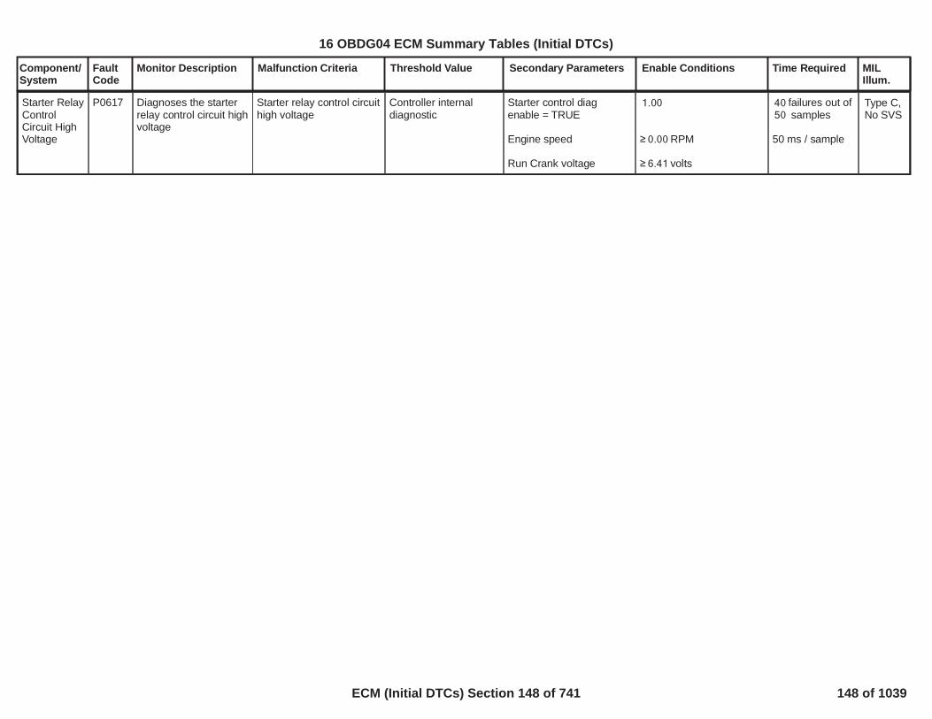
Component/System
FaultCode
Monitor Description Malfunction Criteria Threshold Value Secondary Parameters Enable Conditions Time Required MILIllum.
Starter RelayControlCircuit HighVoltage
P0617 Diagnoses the starterrelay control circuit highvoltage
Starter relay control circuithigh voltage
Controller internaldiagnostic
Starter control diagenable = TRUE
Engine speed
Run Crank voltage
1.00
RPM0.00
volts6.41
failures out of40samples50
50 ms / sample
Type C,No SVS
149
16 OBDG04 ECM Summary Tables (Initial DTCs)
ECM (Initial DTCs) Section 148 of 741 148 of 1039

Component/System
FaultCode
Monitor Description Malfunction Criteria Threshold Value Secondary Parameters Enable Conditions Time Required MILIllum.
Fuel PumpRelayControlCircuit Open
P0627 Diagnoses the fuelpump relay control highside driver circuit forcircuit faults
Voltage high during driveroff state (indicates opencircuit)
Open circuit: 200 K impedance
between signal andcontroller ground
Run/Crank Voltage
Engine Speed
Voltage volts11.00
RPM0
failures out of8samples10
250 ms / sample
Type B,2 Trips
Note: Incertaincontrollers P0629may alsoset (FuelPumpRelayControlShort toPower)
150
16 OBDG04 ECM Summary Tables (Initial DTCs)
ECM (Initial DTCs) Section 149 of 741 149 of 1039

Component/System
FaultCode
Monitor Description Malfunction Criteria Threshold Value Secondary Parameters Enable Conditions Time Required MILIllum.
Fuel PumpRelayControlCircuit LowVoltage
P0628 Diagnoses the fuelpump relay control highside driver circuit forcircuit faults
Voltage low during driveron state (indicates shortto ground)
Short to ground: 0.5 impedance
between signal andcontroller ground
Run/Crank Voltage
Engine Speed
Voltage volts11.00
RPM0
failures out of8samples10
250 ms / sample
Type B,2 Trips
151
16 OBDG04 ECM Summary Tables (Initial DTCs)
ECM (Initial DTCs) Section 150 of 741 150 of 1039

Component/System
FaultCode
Monitor Description Malfunction Criteria Threshold Value Secondary Parameters Enable Conditions Time Required MILIllum.
Fuel PumpRelayControlCircuit HighVoltage
P0629 Diagnoses the fuelpump relay control highside driver circuit forcircuit faults
Voltage high during driveroff state (indicates shortto power)
Short to power: 0.5 impedance
between signal andcontroller power
Run/Crank Voltage
Engine Speed
Voltage volts11.00
RPM0
failures out of8samples10
250 ms / sample
Type B,2 Trips
Note: Incertaincontrollers P0627may alsoset (FuelPumpRelayControlOpenCircuit)
152
16 OBDG04 ECM Summary Tables (Initial DTCs)
ECM (Initial DTCs) Section 151 of 741 151 of 1039

Component/System
FaultCode
Monitor Description Malfunction Criteria Threshold Value Secondary Parameters Enable Conditions Time Required MILIllum.
HWIO reports that writingto NVM (at shutdown) willnot succeed
Diagnostic runsat controllerpower up.
PowertrainInternalControlModuleEEPROMError
P062F This DTC detects aNVM long termperformance.
Type B,2 Trips
HWIO reports theassembly calibrationintegrity check has failed
Diagnostic runsat controllerpower up.
153
16 OBDG04 ECM Summary Tables (Initial DTCs)
ECM (Initial DTCs) Section 152 of 741 152 of 1039

Component/System
FaultCode
Monitor Description Malfunction Criteria Threshold Value Secondary Parameters Enable Conditions Time Required MILIllum.
VIN NotProgrammedorMismatched- EngineControlModule(ECM)
P0630 This DTC checks thatthe VIN is correctlywritten
At least one of theprogrammed VIN digits
= 00 or FF OBD ManufacturerEnable Counter
= 0 250 ms / testContinuous
Type A,1 Trips
154
16 OBDG04 ECM Summary Tables (Initial DTCs)
ECM (Initial DTCs) Section 153 of 741 153 of 1039

Component/System
FaultCode
Monitor Description Malfunction Criteria Threshold Value Secondary Parameters Enable Conditions Time Required MILIllum.
5 VoltReference#1 Circuit
P0641 Detects a continuous orintermittent short on the5 volt reference circuit#1
ECM Vref1 <or ECM Vref1 >or the difference betweenECM filtered Vref1 andVref1 >
4.8755.125
0.0495
Run/Crank voltage >6.41
/19 39counts or0.1875sec continuous;
12.5 ms/count inmain processor
Type A,1 Trips
155
16 OBDG04 ECM Summary Tables (Initial DTCs)
ECM (Initial DTCs) Section 154 of 741 154 of 1039

Component/System
FaultCode
Monitor Description Malfunction Criteria Threshold Value Secondary Parameters Enable Conditions Time Required MILIllum.
MalfunctionIndicatorLamp (MIL)ControlCircuit(ODM) Open
P0650 Diagnoses themalfunction indicatorlamp control low sidedriver circuit for circuitfaults.
Voltage low during driveroff state (indicates opencircuit)
Open circuit: 200 K impedance
between signal andcontroller ground
Run/Crank Voltage
Remote Vehicle Start isnot active
Voltage volts11.00 failures out of1samples1
50 ms / sample
Type B,No MIL
NO MIL
Note: IncertaincontrollersP263Amay alsoset (MILControlShort toGround)
156
16 OBDG04 ECM Summary Tables (Initial DTCs)
ECM (Initial DTCs) Section 155 of 741 155 of 1039

Component/System
FaultCode
Monitor Description Malfunction Criteria Threshold Value Secondary Parameters Enable Conditions Time Required MILIllum.
5 VoltReference#2 Circuit
P0651 Detects a continuous orintermittent short on the5 volt reference circuit#2
ECM Vref2 <or ECM Vref2 >or the difference betweenECM filtered Vref2 andVref2 >
4.8755.125
0.0495
Run/Crank voltage >6.41
/19 39counts or0.1875sec continuous;
12.5 ms/count inmain processor
Type A,1 Trips
157
16 OBDG04 ECM Summary Tables (Initial DTCs)
ECM (Initial DTCs) Section 156 of 741 156 of 1039

Component/System
FaultCode
Monitor Description Malfunction Criteria Threshold Value Secondary Parameters Enable Conditions Time Required MILIllum.
Shared HighSide Drive#1 ControlCircuit Low(STG) -(GEN IIIControllersONLY)
P0658 Diagnoses shared highside driver circuit lowvoltage
Shared high side drive #1control circuit low voltage
Controller internaldiagnostic
Shared high side drive #1low diag enable
Powertrain relay voltage
Run Crank voltage
Powertrain relay state
= 1.00
>= 11.00
> 6.00
= ON
failures out of20samples25
100 ms / sample
Type B,2 Trips
158
16 OBDG04 ECM Summary Tables (Initial DTCs)
ECM (Initial DTCs) Section 157 of 741 157 of 1039

Component/System
FaultCode
Monitor Description Malfunction Criteria Threshold Value Secondary Parameters Enable Conditions Time Required MILIllum.
Shared HighSide Drive#1 ControlCircuit High(STP) -(GEN IIIControllersONLY)
P0659 Diagnoses shared highside driver circuit lowvoltage
Shared high side drive #1control circuit low voltage
Controller internaldiagnostic
Shared high side drive #1diag enable
Powertrain relay voltage
Run Crank voltage
Powertrain relay state
= 1.00
>= 11.00
> 6.00
= ON
failures out of20samples25
100 ms / sample
Type B,2 Trips
159
16 OBDG04 ECM Summary Tables (Initial DTCs)
ECM (Initial DTCs) Section 158 of 741 158 of 1039

Component/System
FaultCode
Monitor Description Malfunction Criteria Threshold Value Secondary Parameters Enable Conditions Time Required MILIllum.
PowertrainRelayControl(ODM) Open
P0685 Diagnoses thepowertrain relay controllow side driver circuitfor circuit faults
Voltage low during driveroff state (indicates opencircuit)
Open Circuit: 200 K ohms
impedance betweensignal and controllerground
Run/Crank Voltage Voltage volts11.00 failures out of8samples10
250 ms / sample
Type B,2 Trips
Note: Incertaincontrollers P0686may alsoset(PowertrainRelayControlShort toGround).
160
16 OBDG04 ECM Summary Tables (Initial DTCs)
ECM (Initial DTCs) Section 159 of 741 159 of 1039
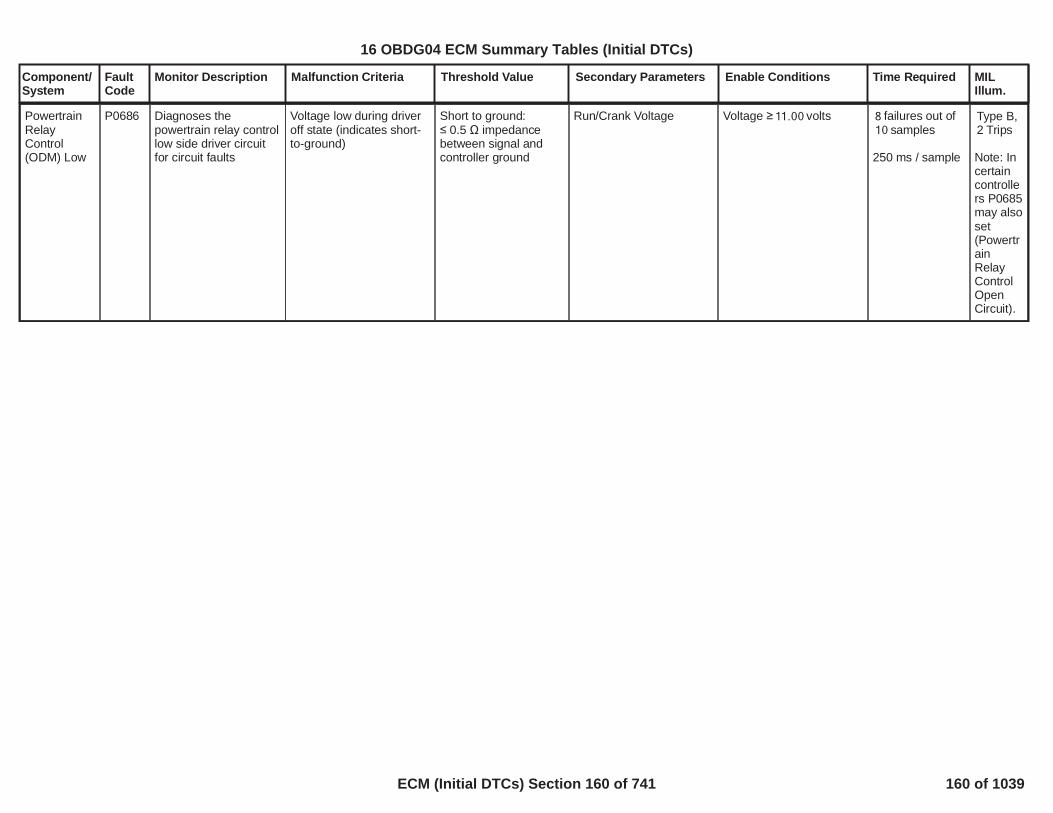
Component/System
FaultCode
Monitor Description Malfunction Criteria Threshold Value Secondary Parameters Enable Conditions Time Required MILIllum.
PowertrainRelayControl(ODM) Low
P0686 Diagnoses thepowertrain relay controllow side driver circuitfor circuit faults
Voltage low during driveroff state (indicates short-to-ground)
Short to ground: 0.5 impedance
between signal andcontroller ground
Run/Crank Voltage Voltage volts11.00 failures out of8samples10
250 ms / sample
Type B,2 Trips
Note: Incertaincontrollers P0685may alsoset(PowertrainRelayControlOpenCircuit).
161
16 OBDG04 ECM Summary Tables (Initial DTCs)
ECM (Initial DTCs) Section 160 of 741 160 of 1039

Component/System
FaultCode
Monitor Description Malfunction Criteria Threshold Value Secondary Parameters Enable Conditions Time Required MILIllum.
PowertrainRelayControl(ODM) High
P0687 Diagnoses thepowertrain relay controllow side driver circuitfor circuit faults
Voltage high during driveron state (indicates shortto power)
Short to power: 0.5 impedance
between signal andcontroller power
Run/Crank Voltage Voltage volts11.00 failures out of8samples10
250 ms / sample
Type B,2 Trips
162
16 OBDG04 ECM Summary Tables (Initial DTCs)
ECM (Initial DTCs) Section 161 of 741 161 of 1039

Component/System
FaultCode
Monitor Description Malfunction Criteria Threshold Value Secondary Parameters Enable Conditions Time Required MILIllum.
ControlModulePower RelayFeedbackCircuit LowVoltage
P0689 Diagnoses controlmodule relay feedbackcircuit low voltage
Control module relayfeedback circuit lowvoltage
Powertrain relayvoltage <= 5.00
Powertrain relay short lowdiagnostic enable
Run Crank voltage
Powertrain relay state
= 1.00
> 9.00
= ON
failures out of5samples6
1000 ms /sample
Type C,No SVS
163
16 OBDG04 ECM Summary Tables (Initial DTCs)
ECM (Initial DTCs) Section 162 of 741 162 of 1039

Component/System
FaultCode
Monitor Description Malfunction Criteria Threshold Value Secondary Parameters Enable Conditions Time Required MILIllum.
PowertrainRelayFeedbackCircuit High
P0690 This DTC is a check todetermine if thePowertrain relay isfunctioning properly.
Powertrain Relay Voltage >= volts will4.00increment the failcounter
Powertrain relaycommanded “OFF”
No active DTCs:
>= seconds2.00
PowertrainRelayStateOn_FA
failures out50of samples63
100ms / Sample
Type B,2 Trips
164
16 OBDG04 ECM Summary Tables (Initial DTCs)
ECM (Initial DTCs) Section 163 of 741 163 of 1039

Component/System
FaultCode
Monitor Description Malfunction Criteria Threshold Value Secondary Parameters Enable Conditions Time Required MILIllum.
Cooling Fan1 RelayControlCircuit LowVoltage(ODM)
P0691 Diagnoses the coolingfan 1 relay control lowside driver circuit forcircuit faults
Voltage low during driveroff state (indicates short-to-ground)
Short to ground: 0.5 impedance
between signal andcontroller ground
Powertrain Relay Voltage Voltage volts11.00 failures out of50samples63
100 ms / sample
Type B,2 Trips
Note: Incertaincontrollers P0480may alsoset (Fan1 OpenCircuit).
165
16 OBDG04 ECM Summary Tables (Initial DTCs)
ECM (Initial DTCs) Section 164 of 741 164 of 1039

Component/System
FaultCode
Monitor Description Malfunction Criteria Threshold Value Secondary Parameters Enable Conditions Time Required MILIllum.
Cooling Fan1 RelayControlCircuit HighVoltage(ODM)
P0692 Diagnoses the coolingfan 1 relay control lowside driver circuit forcircuit faults
Voltage high during driveron state (indicates shortto power)
Short to power: 0.5 impedance
between signal andcontroller power
Powertrain Relay Voltage Voltage volts11.00 failures out of50samples63
100 ms / sample
Type B,2 Trips
166
16 OBDG04 ECM Summary Tables (Initial DTCs)
ECM (Initial DTCs) Section 165 of 741 165 of 1039

Component/System
FaultCode
Monitor Description Malfunction Criteria Threshold Value Secondary Parameters Enable Conditions Time Required MILIllum.
5 VoltReference#3 Circuit
P0697 Detects a continuous orintermittent short on the5 volt reference circuit#3
ECM Vref3 <or ECM Vref3 >or the difference betweenECM filtered Vref3 andVref3 >
4.8755.125
0.0495
Run/Crank voltage >6.41
/19 39counts or0.1875sec continuous;12.5 ms/count inmain processor
Type A,1 Trips
167
16 OBDG04 ECM Summary Tables (Initial DTCs)
ECM (Initial DTCs) Section 166 of 741 166 of 1039

Component/System
FaultCode
Monitor Description Malfunction Criteria Threshold Value Secondary Parameters Enable Conditions Time Required MILIllum.
5 VoltReference#4 Circuit
P06A3 Detects a continuous orintermittent short on the5 volt reference circuit#4
ECM Vref4 <or ECM Vref4 >or the difference betweenECM filtered Vref4 andVref4 >
4.8755.125
0.0495
Run/Crank voltage >6.41
/19 39counts or0.1875sec continuous;
12.5 ms/count inmain processor
Type A,1 Trips
168
16 OBDG04 ECM Summary Tables (Initial DTCs)
ECM (Initial DTCs) Section 167 of 741 167 of 1039

Component/System
FaultCode
Monitor Description Malfunction Criteria Threshold Value Secondary Parameters Enable Conditions Time Required MILIllum.
Transmission ControlModule(TCM)RequestedMILIllumination
P0700 Monitors the TCM MILrequest message todetermine when theTCM has detected aMIL illuminating fault.
Transmission Emissions-Related DTC set
Time since power-up 3seconds
Continuous Type A,No MIL
169
16 OBDG04 ECM Summary Tables (Initial DTCs)
ECM (Initial DTCs) Section 168 of 741 168 of 1039

Component/System
FaultCode
Monitor Description Malfunction Criteria Threshold Value Secondary Parameters Enable Conditions Time Required MILIllum.
TractionControlTorqueRequestCircuit
P0856 Determines if torquerequest from theEBTCM is valid
Protection error - SerialCommunication 2’scomplement message -($1C7/$1C9 for enginetorque, $1CA/$1C6 foraxle torque)
ORRolling count error -Serial Communicationmessage ($1C7/$1C9 forengine torque, $1CA/$1C6 for axle torque)rolling count index value
ORMulti-transition error -EBCM torque interventiontype request change
ORRange Error - Torquerequest greater thantorque request diagnosticmaximum threshold
Message <> 2'scomplement ofmessage
Message rolling countvalue <> previousmessage rolling countvalue plus one
Requested torqueintervention typetoggles from anincreasing request tonot an increasingrequest then back toan increasing requestwithin 200ms
> Nm250for engine torquebased traction torquesystem,OR> Nm250for axle torque basedtraction torque system
Serial communication toEBTCM (U0108)
Power ModeEngine Running
Status of traction inGMLAN message ($4E9)
No loss ofcommunication
= Run= True
= Traction Present
>= protection6value errorsout of
samples10
Performed onevery receivedmessage
>= rolling6count errorsout of
samples10
Performed onevery receivedmessage
>= multi-3transitions errorsout of 5 samples.
Performed every200 ms
>= range6errors out of10 samples
Performed onevery receivedmessage
Type C,No SVSSafetySpecialType C
170
16 OBDG04 ECM Summary Tables (Initial DTCs)
ECM (Initial DTCs) Section 169 of 741 169 of 1039

Component/System
FaultCode
Monitor Description Malfunction Criteria Threshold Value Secondary Parameters Enable Conditions Time Required MILIllum.
EngineCoolantTemperatureSensor NotPlausible)(TSRD
P111E This DTC detects adifference betweenECT and two othertemp sensors after asoak condition.
Sensor usagedefinitions:
Sensor1 =CeECTR_e_ECT_Snsr(Sensor1 is the tempsensor most impacted bythe block heater (ifequipped))
Sensor2 =CeECTR_e_IAT_Snsr
Sensor3 =CeECTR_e_OAT_Snsr
===================
A failure will be reported ifany of the following occur:
1) Sensor1 power upabsolute temp differenceto Sensor2 and Sensor3is(Sensor1 fast fail) .
2) Sensor1 power uptemp is greater thanSensor2 and Sensor3 inthis range:(and a block heater hasnot been detected)
3) Sensor1 power uptemp is lower thanSensor2 and Sensor3 bythis amount:
4) Sensor1 power uptemp is Sensor2 and
ºC100.0
and < ºC20.0 100.0
Deg ºC20.0
No Active DTC's
Engine Off Soak TimePropulsion Off Soak TimeNon-volatile memoryinitization
Test complete this tripTest aborted this tripTest disabled this tripAmbientLowFuelCondition Diag
==================Block Heater detection isenabled when either ofthe following occurs:
1) Sensor1 power uptemp is greater thanSensor2 and Sensor3 inthis range:
2) Cranking time
==================Block Heater is detected
VehicleSpeedSensor_FAIAT_SensorCircuitFATHMR_RCT_Sensor_Ckt_FAECT_Sensor_Ckt_FAEngineModeNotRunTimerErrorEngineModeNotRunTimer_FAOAT_PtEstFiltFAOAT_PtEstRawFAPSAR_PropSysInactveCrs_FADRER_DiagSystemDsbl
> seconds28,800> seconds25,200
= Not occurred
= False= False= False ºC-7
= False
==================
ºC and <20.0ºC100.0
< Seconds409.6
==================
1 failure to setDTC
1 sec/ sample
Once per validcold start
Type B,2 Trips
171
16 OBDG04 ECM Summary Tables (Initial DTCs)
ECM (Initial DTCs) Section 170 of 741 170 of 1039

Component/System
FaultCode
Monitor Description Malfunction Criteria Threshold Value Secondary Parameters Enable Conditions Time Required MILIllum.
Sensor3 by ºC and20.0the time spent crankingthe engine without startingis seconds with409.6theLowFuelConditionDiag
= False
and diagnostic is abortedwhen 1) or 2) occurs.
1a) IAT monitoring isenabled after the followingVehicle drive constraints1b) Drive time
1c) Vehicle speed
1d) Additional Vehicledrive time is provided to1b when Vehicle speed isbelow 1c as follows:
1e) IAT drops from powerup IAT
2a) ECT monitoring isenabled after engine startin the following engine runtime window
2b) Sensor1 tempderivative during the testis:
2c) Consectutive samplesof 2b) being true are:
==================Diagnostic is abortedwhen 3) or 4) occurs:
3) Engine run time withvehicle speed below 1b
4) Engine off time (i.e.auto stop) during Blockheater detection
> Seconds with400
> MPH and14.9
times the seconds1.00with vehicle speed below1b
ºC8.0
<= seconds <=1.0 40.0
< ºC/sec-0.10
samples4
===================
Seconds1,800
Seconds300.0
172
16 OBDG04 ECM Summary Tables (Initial DTCs)
ECM (Initial DTCs) Section 171 of 741 171 of 1039

Component/System
FaultCode
Monitor Description Malfunction Criteria Threshold Value Secondary Parameters Enable Conditions Time Required MILIllum.
Fuel RailPressure(FRP)Sensor BCircuit LowVoltage
P127C Determine when ashort circuit to groundaffects fuel railpressure (secondary)sensor.
Fuel rail pressure sensoroutput (as percentage ofsupply voltage) < %4.3
Starter motor is notengagedOR
Starter motor has beenengaged for a timeOR
Run crank voltage
s15
> V8.4
failures out of38samples55
OR
continuous22failures out of
samples55
6.25 ms/samples
Type A,1 Trips
173
16 OBDG04 ECM Summary Tables (Initial DTCs)
ECM (Initial DTCs) Section 172 of 741 172 of 1039

Component/System
FaultCode
Monitor Description Malfunction Criteria Threshold Value Secondary Parameters Enable Conditions Time Required MILIllum.
Fuel RailPressure(FRP)Sensor BCircuit HighVoltage
P127D Determine when ashort circuit to voltageaffects fuel railpressure (secondary)sensor.
Fuel rail pressure sensoroutput (as percentage ofsupply voltage) < %94.8
Starter motor is notengagedOR
Starter motor has beenengaged for a timeOR
Run crank voltageNo lowignition voltage
s15
> V8.4
failures out of38samples76
OR
continuous22failures out of
samples76
6.25 ms/samples
Type A,1 Trips
174
16 OBDG04 ECM Summary Tables (Initial DTCs)
ECM (Initial DTCs) Section 173 of 741 173 of 1039

Component/System
FaultCode
Monitor Description Malfunction Criteria Threshold Value Secondary Parameters Enable Conditions Time Required MILIllum.
EGR SlowResponse -IncreasingFlow
P140B This monitor (inincreasing flowdirection) detectsfailures in the airsystem such to not fulfilthe request of EGRflow in the intakemanifold duringtransient conditions. Itworks only closed loopEGR control zone.This monitor is used todetect any malfunctionin the EGR system thatlead to slow down theair control causing thevehicle's emissions toexceed OBDII limits.The aim of the EGRflow slow responsemonitor is to detectsmall leakages in thepipe after thecompressor or in theintake/exhaustmanifold. This monitorcould also detect slowresponding EGRvalves, or skewedMAF sensor vanessince the boostpressure is usuallycontrolled by theturbocharger actuator.Slow respondingthrottle and VGT vanescould also affect theEGR flow responsetime.
Error difference betweenthe desired EGR rate andthe actual EGR rateduring transient air controlconditions. The absoluteerror is averaged over acalibrate-able cumulativetransient time.
>P140B: IncreasingEGR slow responsethreshold[%]
Calibration on diagnosticenabling
Engine Running
Cranking ignition in range
Relay voltage in range
Air Control is Active (aircontrol in closed loop)
Air control active conditionlasts for a time
Desired EGR rate
A combustion modetransition is NOT active
OBD Coolant EnableCriteria
Exhaust manifoldpressure is valid
Throttle measured
P140B, P140C: EGRslow response enabling==TRUE
==TRUE
Battery voltage >[V]11.00
Powertrain relay voltage >[V]11.00
AIC_AirCntrlShtOffAction==Ce_AICR_e_CntrlActv
> [s]10.00
> 0 [%]
==TRUE
==TRUE
EXM_ExhMnfdPresNotVld==FALSE
> [%]90.00
Test is evaluatedafter theenablingconditions aresatisfied for anumber ofsamples
>= 200.00
sampling time is25ms
Type B,2 Trips
175
16 OBDG04 ECM Summary Tables (Initial DTCs)
ECM (Initial DTCs) Section 174 of 741 174 of 1039

Component/System
FaultCode
Monitor Description Malfunction Criteria Threshold Value Secondary Parameters Enable Conditions Time Required MILIllum.
position
Nominal valve total flow isvalid
Outside air temperature
Ambient air pressure
Engine speed
Desired fuel quantity
Exhaust manifoldpressure
Desired air request issteady state:AirReq-AirReqOld
Air control tracking error
Check that EGR valveposition is below athresholdORit is above that threshold
EGR_VlvTotFlowNomNotVld==FALSE
> [°C]-7.00
> [kPa]74.80
> [rpm]1,500.00AND< [rpm]3,000.00
> [mm^3]10.00AND< [mm^3]50.00
> [kPa]100.00AND< [kPa]250.00
> [mg/s]-70.00AND< [mg/s]-10.00
< 0 [mg]
< [%]70.00
> [s]0.00
176
16 OBDG04 ECM Summary Tables (Initial DTCs)
ECM (Initial DTCs) Section 175 of 741 175 of 1039

Component/System
FaultCode
Monitor Description Malfunction Criteria Threshold Value Secondary Parameters Enable Conditions Time Required MILIllum.
for a time delay
177
16 OBDG04 ECM Summary Tables (Initial DTCs)
ECM (Initial DTCs) Section 176 of 741 176 of 1039

Component/System
FaultCode
Monitor Description Malfunction Criteria Threshold Value Secondary Parameters Enable Conditions Time Required MILIllum.
EGR SlowResponse -DecreasingFlow
P140C This monitor (indecreasing flowdirection) detectsfailures in the airsystem such to not fulfilthe request of EGRflow in the intakemanifold duringtransient conditions. Itworks only closed loopEGR control zone.This monitor is used todetect any malfunctionin the EGR system thatlead to slow down theair control causing thevehicle's emissions toexceed OBDII limits.The aim of the EGRflow slow responsemonitor is to detectsmall obstructions inthe exhaust pipe. Thismonitor could alsodetect slow respondingEGR valves, orskewed MAF sensorvanes since the boostpressure is usuallycontrolled by theturbocharger actuator.Slow respondingthrottle and VGT vanescould also affect theEGR flow responsetime.
Error difference betweenthe desired EGR rate andthe actual EGR rateduring transient air controlconditions. The absoluteerror is averaged over acalibrate-able cumulativetransient time.
>P140C: DecreasingEGR slow responsethreshold[%]
Calibration on diagnosticenabling
Engine Running
Cranking ignition in range
Relay voltage in range
Air Control is Active (aircontrol in closed loop)
Air control active conditionlasts for a time
Desired EGR rate
A combustion modetransition is NOT active
OBD Coolant EnableCriteria
Exhaust manifoldpressure is valid
Throttle measured
P140B, P140C: EGRslow response enabling==TRUE
==TRUE
Battery voltage > 11.00[V]
Powertrain relay voltage >[V]11.00
AIC_AirCntrlShtOffAction==Ce_AICR_e_CntrlActv
> [s]10.00
> 0 [%]
==TRUE
==TRUE
EXM_ExhMnfdPresNotVld==FALSE
> [%]90.00
Test is evaluatedafter theenablingconditions aresatisfied for anumber ofsamples
>=200.00
sampling time is25ms
Type B,2 Trips
178
16 OBDG04 ECM Summary Tables (Initial DTCs)
ECM (Initial DTCs) Section 177 of 741 177 of 1039

Component/System
FaultCode
Monitor Description Malfunction Criteria Threshold Value Secondary Parameters Enable Conditions Time Required MILIllum.
position
Nominal valve total flow isvalid
Outside air temperature
Ambient air pressure
Engine speed
Desired fuel quantity
Exhaust manifoldpressure
Desired air request issteady state:AirReq-AirReqOld
Air control tracking error
EGR_VlvTotFlowNomNotVld==FALSE
> [°C]-7.00
> [kPa]74.80
> [rpm]1,500.00AND< [rpm]3,000.00
> [mm^3]10.00AND< [mm^3]50.00
> [kPa]100.00AND< [kPa]250.00
> [mg/s]10.00AND< [mg/s]70.00
> 0 [mg]
179
16 OBDG04 ECM Summary Tables (Initial DTCs)
ECM (Initial DTCs) Section 178 of 741 178 of 1039

Component/System
FaultCode
Monitor Description Malfunction Criteria Threshold Value Secondary Parameters Enable Conditions Time Required MILIllum.
Transmission EngineSpeedRequestCircuit
P150C Determines if enginespeed request from theTCM is valid
Serial Communicationrolling count value
Transmission enginespeed protection
+ 1 from previous$19D message(PTEI3)
not equal to 2'scomplement oftransmission enginespeed request +Transmission aliverolling count
Diagnostic enable bit
Engine run time
# of Protect Errors
# of Alive Rolling Errors
No idle diagnostic506/507 code
No Serial communicationloss to TCM
Engine Running
Power mode
1
sec0.50
protect errors within12the sample period 20
rolling count errors out6of 10 samples
IAC_SystemRPM_FA
(U0101)
= TRUE
Run Crank Active
Diagnostic runsin 12.5 ms loop
Type B,2 Trips
180
16 OBDG04 ECM Summary Tables (Initial DTCs)
ECM (Initial DTCs) Section 179 of 741 179 of 1039

Component/System
FaultCode
Monitor Description Malfunction Criteria Threshold Value Secondary Parameters Enable Conditions Time Required MILIllum.
CruiseControlSwitch StateUndertermined
P155A Detects when cruiseswitch state cannot bedetermined, such aslow voltage conditions
cruise switch state isreceived as"undetermined" forgreater than a calibratabletime
fail continuously forgreater than0.5seconds
fail continuouslyfor greater than0.5seconds
Type C,No SVS, specialtype C
181
16 OBDG04 ECM Summary Tables (Initial DTCs)
ECM (Initial DTCs) Section 180 of 741 180 of 1039

Component/System
FaultCode
Monitor Description Malfunction Criteria Threshold Value Secondary Parameters Enable Conditions Time Required MILIllum.
Sensor BusRelayFeedbackCircuit HighVoltage
P157A This DTC checks thatthe Sensor Bus Relayoutput is not stuck high
The Sensor Bus Relayouput is stuck high
>=KeSBRR_Cnt_SB_RlyStkHiFailThrsh withinKeSBRR_Cnt_SB_RlyStkHiSmplThrshsamples
The Sensor Bus Relayoutput has been inactive
>=KeSBRR_t_SB_RelayCommandedOff
Type B,2 Trips
182
16 OBDG04 ECM Summary Tables (Initial DTCs)
ECM (Initial DTCs) Section 181 of 741 181 of 1039

Component/System
FaultCode
Monitor Description Malfunction Criteria Threshold Value Secondary Parameters Enable Conditions Time Required MILIllum.
InternalControlModulePressureRegulator 1ControlPerformance
P163A Current flowing throughmetering unit valve
OR
Current flowing throughmetering unit valve
> A2.80
< A0.05
Powertrain relay voltage
Rail pressure is governedby Metering Unit
No active DTC since keyis on:
V11.0
FHP_MU_DrvrCloseTFTKOFHP_MU_DrvrOpenTFTKO
failures out160of
samples250
6.25 ms/sample
Type B,2 Trips
183
16 OBDG04 ECM Summary Tables (Initial DTCs)
ECM (Initial DTCs) Section 182 of 741 182 of 1039

Component/System
FaultCode
Monitor Description Malfunction Criteria Threshold Value Secondary Parameters Enable Conditions Time Required MILIllum.
InternalControlModulePressureRegulator 2ControlPerformance
P163B Current flowing throughpressure regulator valve
OR
Current flowing throughpressure regulator valve
> A2.80
< A0.05
Powertrain relay voltage
Rail pressure is governedby Pressure Regulator
No active DTC since keyis on:
V11.0
FHP_PR_DrvrCloseTFTKOFHP_PR_DrvrOpenTFTKO
failures out160of
samples250
6.25 ms/sample
Type B,2 Trips
184
16 OBDG04 ECM Summary Tables (Initial DTCs)
ECM (Initial DTCs) Section 183 of 741 183 of 1039

Component/System
FaultCode
Monitor Description Malfunction Criteria Threshold Value Secondary Parameters Enable Conditions Time Required MILIllum.
IgnitionVoltageCorrelation
P1682 Detect a continuous orintermittent out ofcorrelation between theRun/Crank IgnitionVoltage & thePowertrain RelayIgnition Voltage
|Run/Crank – PT RelayIgnition| >
Volts3.00 Powertrain commandedon
AND
(Run/Crank voltage >Table, f(IAT). Seesupporting tables:P1682_PT Relay Pull-inRun/Crank Voltage f(IAT)
OR PT Relay Ignitionvoltage > )5.50
AND
Run/Crank voltage >.5.50
/240 480counts or0.175sec continuous;12.5 ms/count inmain processor
Type A,1 Trips
185
16 OBDG04 ECM Summary Tables (Initial DTCs)
ECM (Initial DTCs) Section 184 of 741 184 of 1039

Component/System
FaultCode
Monitor Description Malfunction Criteria Threshold Value Secondary Parameters Enable Conditions Time Required MILIllum.
Error difference betweenthe desired boostpressure used by theclosed loop boostpressure control and theactual intake manifoldpressure measured by theMAP sensor. The error isaveraged over a calibrate-able cumulative transienttime.
The setpoint used forclosed loop control is theintake manifold pressure:in this situation thediagnostic monitors theboost pressure closedloop control tracking error.
>P168A: Positiveboost slow responsethreshold[kPa]
Calibration on diagnosticenabling
Engine Running
Cranking ignition in range
Relay voltage in range
Difficult launch NOTdetected
Boost control in closedloop
Boost control in closedloop condition lasts for atime
No active transition fromone combustion mode toanother
Engine CoolantTemperatureOROBD Coolant EnableCriteria
P168A, P168B: Boostpressure slow responseenabling==TRUE
==TRUE
Battery voltage > 11.00[V]
Powertrain relay voltage >[V]11.00
Refer to"LDT_DifficultLaunchActive" Free Form
==TRUEAIC_BstCntrlCL
> [s]0.20
==TRUE
> [°C]70.00
==TRUE
Test is evaluatedafter theenablingconditions aresatisfied for anumber ofsamples
>= 300.00
sampling time is25ms
Turbocharger BoostControl ASlowResponse -IncreasingPressure
P168A This monitor (inincreasing pressuredirection) detectsfailures in the chargingair system such to notfulfil the request ofboost pressure in theintake manifold. Itworks only in transientclosed loop boostpressure control zone.This monitor is used todetect any malfunctionin the boost pressuresystem that lead toslow down the boostpressure controlcausing the vehicle'semissions to exceedOBDII limits.The aim of the boostpressure slowresponse monitor is todetect small leakagesin the pipe after thecompressor or in theintake/exhaust manifold(increasing pressure).This monitor could alsodetect slow respondingVGT vanes since theboost pressure isusually controlled bythe turbochargeractuator. Slowresponding throttle andEGR valves could alsoaffect the boostpressure responsetime.
Type X,No MIL
16 OBDG04 ECM Summary Tables (Initial DTCs)
ECM (Initial DTCs) Section 185 of 741 185 of 1039

Component/System
FaultCode
Monitor Description Malfunction Criteria Threshold Value Secondary Parameters Enable Conditions Time Required MILIllum.
Outside air temperature
Ambient air pressure
Throttle Valve measuredposition
Engine speed
Desired fuel quantity
Desired boost pressure issteady state:BstRespTgt -BstRespTgAirReqOld
Boost pressure currenttracking error (notaveraged over thecumulative transient time)
No active DTCs
> [°C]-7.00
> [kPa]69.60
>= [%]90.00
> [rpm]1,500.00AND< [rpm]3,500.00
> [mm^3]30.00AND< [mm^3]100.00
> [kPa/s]2.00AND< 100.00[kPa/s]
> 0 [kPa]
AIC_BstSysDiagDenomDsbl==FALSE
Error difference betweenthe desired intake boostpressure and the actualintake manifold pressuremeasured by the MAP
>P168A: Positiveboost slow responsethreshold[kPa]
Calibration on diagnosticenabling
P168A, P168B: Boostpressure slow responseenabling==TRUE
Test is evaluatedafter theenablingconditions aresatisfied for a
16 OBDG04 ECM Summary Tables (Initial DTCs)
ECM (Initial DTCs) Section 186 of 741 186 of 1039

Component/System
FaultCode
Monitor Description Malfunction Criteria Threshold Value Secondary Parameters Enable Conditions Time Required MILIllum.
sensor. The error isaveraged over a calibrate-able cumulative transienttime.
The setpoint used forclosed loop control is theconversion of the desiredupstream throttle boostpressure (target) indesired intake boostpressure.The conversion of thesetpoint is donecalculating the pressuredrop over the throttlevalve that is strictlydependent on the valveposition.
Engine Running
Cranking ignition in range
Relay voltage in range
Difficult launch NOTdetected
Boost control in closedloop
Boost control in closedloop condition lasts for atime
No active transition fromone combustion mode toanother
Engine CoolantTemperatureOROBD Coolant EnableCriteria
Outside air temperature
Ambient air pressure
==TRUE
Battery voltage >[V]11.00
Powertrain relay voltage >[V]11.00
Refer to"LDT_DifficultLaunchActive" Free Form
==TRUEAIC_BstCntrlCL
> [s]0.20
==TRUE
> [°C]70.00
==TRUE
> [°C]-7.00
> [kPa]69.60
number ofsamples
>= 300.00
sampling time is25ms
16 OBDG04 ECM Summary Tables (Initial DTCs)
ECM (Initial DTCs) Section 187 of 741 187 of 1039

Component/System
FaultCode
Monitor Description Malfunction Criteria Threshold Value Secondary Parameters Enable Conditions Time Required MILIllum.
Throttle Valve measuredposition
Engine speed
Desired fuel quantity
Desired boost pressure issteady state:BstRespTgt -BstRespTgAirReqOld
Boost pressure currenttracking error (notaveraged over thecumulative transient time)
No active DTCs
>= [%]100.00
> [rpm]1,500.00AND< [rpm]3,500.00
> [mm^3]30.00AND< [mm^3]100.00
> [kPa/s]2.00AND< [kPa/s]100.00
> 0 [kPa]
AIC_BstSysDiagDenomDsbl==FALSE
16 OBDG04 ECM Summary Tables (Initial DTCs)
ECM (Initial DTCs) Section 188 of 741 188 of 1039

Component/System
FaultCode
Monitor Description Malfunction Criteria Threshold Value Secondary Parameters Enable Conditions Time Required MILIllum.
Error difference betweenthe desired boostpressure used by theclosed loop boostpressure control and theactual intake manifoldpressure measured by theMAP sensor. The error isaveraged over a calibrate-able cumulative transienttime.
The setpoint used forclosed loop control is theintake manifold pressure:in this situation thediagnostic monitors theboost pressure closedloop control tracking error.
>P168B: Negativeboost slow responsethreshold[kPa]
Calibration on diagnosticenabling
Engine Running
Cranking ignition in range
Relay voltage in range
Difficult launch NOTdetected
Boost control in closedloop
Boost control in closedloop condition lasts for atime
No active transition fromone combustion mode toanother
Engine CoolantTemperatureOROBD Coolant EnableCriteria
P168A, P168B: Boostpressure slow responseenabling==TRUE
==TRUE
Battery voltage >[V]11.00
Powertrain relay voltage >[V]11.00
Refer to"LDT_DifficultLaunchActive" Free Form
==TRUEAIC_BstCntrlCL
> [s]0.20
==TRUE
> [°C]70.00
==TRUE
Test is evaluatedafter theenablingconditions aresatisfied for anumber ofsamples
>= 250.00
sampling time is25ms
Turbocharger BoostControl ASlowResponse -DecreasingPressure
P168B This monitor (indecreasing pressuredirection) detectsfailures in the chargingair system such to notfulfil the request ofboost pressure in theintake manifold. Itworks only in transientclosed loop boostpressure control zone.This monitor is used todetect any malfunctionin the boost pressuresystem that lead toslow down the boostpressure controlcausing the vehicle'semissions to exceedOBDII limits.The aim of the boostpressure slowresponse monitor is todetect smallobstructions in theexhaust pipe(decreasing pressure).This monitor could alsodetect slow respondingVGT vanes since theboost pressure isusually controlled bythe turbochargeractuator. Slowresponding throttle andEGR valves could alsoaffect the boostpressure responsetime.
Type X,No MIL
190
16 OBDG04 ECM Summary Tables (Initial DTCs)
ECM (Initial DTCs) Section 189 of 741 189 of 1039

Component/System
FaultCode
Monitor Description Malfunction Criteria Threshold Value Secondary Parameters Enable Conditions Time Required MILIllum.
Outside air temperature
Ambient air pressure
Throttle Valve measuredposition
Engine speed
Desired fuel quantity
Desired boost pressure issteady state:BstRespTgt -BstRespTgAirReqOld
Boost pressure currenttracking error (notaveraged over thecumulative transient time)
No active DTCs
> [°C]-7.00
> [kPa]69.60
>= [%]90.00
> [rpm]1,500.00AND< [rpm]3,500.00
> [mm^3]30.00AND< [mm^3]100.00
> [kPa/s]-125.00
< [kPa/s]-2.00
< 0 [kPa]
AIC_BstSysDiagDenomDsbl==FALSE
Error difference betweenthe desired intake boostpressure and the actualintake manifold pressuremeasured by the MAP
>P168B: Negativeboost slow responsethreshold[kPa]
Calibration on diagnosticenabling
P168A, P168B: Boostpressure slow responseenabling==TRUE
Test is evaluatedafter theenablingconditions aresatisfied for a
191
16 OBDG04 ECM Summary Tables (Initial DTCs)
ECM (Initial DTCs) Section 190 of 741 190 of 1039

Component/System
FaultCode
Monitor Description Malfunction Criteria Threshold Value Secondary Parameters Enable Conditions Time Required MILIllum.
sensor. The error isaveraged over a calibrate-able cumulative transienttime.
The setpoint used forclosed loop control is theconversion of the desiredupstream throttle boostpressure (target) indesired intake boostpressure.The conversion of thesetpoint is donecalculating the pressuredrop over the throttlevalve that is strictlydependent on the valveposition.
Engine Running
Cranking ignition in range
Relay voltage in range
Difficult launch NOTdetected
Boost control in closedloop
Boost control in closedloop condition lasts for atime
No active transition fromone combustion mode toanother
Engine CoolantTemperatureOROBD Coolant EnableCriteria
Outside air temperature
Ambient air pressure
==TRUE
Battery voltage >[V]11.00
Powertrain relay voltage >[V]11.00
Refer to"LDT_DifficultLaunchActive" Free Form
==TRUEAIC_BstCntrlCL
> [s]0.20
==TRUE
> [°C]70.00
==TRUE
> [°C]-7.00
> [kPa]69.60
number ofsamples
>= 250.00
sampling time is25ms
192
16 OBDG04 ECM Summary Tables (Initial DTCs)
ECM (Initial DTCs) Section 191 of 741 191 of 1039

Component/System
FaultCode
Monitor Description Malfunction Criteria Threshold Value Secondary Parameters Enable Conditions Time Required MILIllum.
Throttle Valve measuredposition
Engine speed
Desired fuel quantity
Desired boost pressure issteady state:BstRespTgt -BstRespTgAirReqOld
Boost pressure currenttracking error (notaveraged over thecumulative transient time)
No active DTCs
>= [%]100.00
> [rpm]1,500.00AND< [rpm]3,500.00
> [mm^3]30.00AND< [mm^3]100.00
> [kPa/s]-125.00AND< [kPa/s]-2.00
< 0 [kPa]
AIC_BstSysDiagDenomDsbl==FALSE
193
16 OBDG04 ECM Summary Tables (Initial DTCs)
ECM (Initial DTCs) Section 192 of 741 192 of 1039

Component/System
FaultCode
Monitor Description Malfunction Criteria Threshold Value Secondary Parameters Enable Conditions Time Required MILIllum.
IgnitionVoltageCorrelation#2
P16A7 Detect a continuous orintermittent out ofcorrelation between theRun/Crank IgnitionVoltage & thePowertrain RelayIgnition Voltage #2
|Run/Crank – PT RelayIgnition| >
Volts3.00 Powertrain commandedon
AND
(Run/Crank voltage >Table, f(IAT). Seesupporting tables:P1682_PT Relay Pull-inRun/Crank Voltage f(IAT)
OR PT Relay Ignitionvoltage > )5.50
AND
Run/Crank voltage >.5.50
/240 480counts or0.175sec continuous;12.5 ms/count inmain processor
Type A,1 Trips
194
16 OBDG04 ECM Summary Tables (Initial DTCs)
ECM (Initial DTCs) Section 193 of 741 193 of 1039

Component/System
FaultCode
Monitor Description Malfunction Criteria Threshold Value Secondary Parameters Enable Conditions Time Required MILIllum.
EngineControlsIgnitionRelayFeedbackCircuit 2 LowVoltage -(GEN IIIControllersONLY)
P16AF Diagnoses ignitionfeedback circuit 2 lowvoltage
Engine controls ignitionrelay feedback circuit 2low voltage
Relay voltage <= 5.00 Powertrain relay low diagenable
Powertrain relay voltage
Run Crank voltage
Powertrain relay state
= 1.00
>= 11.00
> 9.00
= ON
failures out of5samples6
1000 ms /sample
Type C,No SVS
195
16 OBDG04 ECM Summary Tables (Initial DTCs)
ECM (Initial DTCs) Section 194 of 741 194 of 1039

Component/System
FaultCode
Monitor Description Malfunction Criteria Threshold Value Secondary Parameters Enable Conditions Time Required MILIllum.
EngineControlsIgnitionRelayFeedbackCircuit 2High Voltage- (GEN IIIControllersONLY)
P16B3 Diagnoses ignitionfeedback circuit 2 highvoltage
Engine controls ignitionrelay feedback circuit 2high voltage
Relay voltage >= 4.00 Powertrain relay high diagenable
Powertrain relay state
= 1.00
= INACTIVE
failures out of50samples63
100 ms / sample
Type B,2 Trips
196
16 OBDG04 ECM Summary Tables (Initial DTCs)
ECM (Initial DTCs) Section 195 of 741 195 of 1039

Component/System
FaultCode
Monitor Description Malfunction Criteria Threshold Value Secondary Parameters Enable Conditions Time Required MILIllum.
Sensor BusRelayControlCircuit
P16D7 This DTC checks thatthe Sensor Bus Relayoutput circuit is not anopen circuit
The Sensor Bus Relayoutput circuit is open
>=KeSBRD_Cnt_RlyOpenFail withinKeSBRD_Cnt_RlyOpenSmpl samples
The Sensor Bus RelayCommanded Output state
= Off Type A,1 Trips
197
16 OBDG04 ECM Summary Tables (Initial DTCs)
ECM (Initial DTCs) Section 196 of 741 196 of 1039

Component/System
FaultCode
Monitor Description Malfunction Criteria Threshold Value Secondary Parameters Enable Conditions Time Required MILIllum.
Sensor BusRelayControlCircuit Low
P16D8 This DTC checks thatthe Sensor Bus Relayoutput circuit is notshorted to ground
The Sensor Bus Relayoutput circuit is shorted toground
>=KeSBRD_Cnt_RlyGshtFail withinKeSBRD_Cnt_RlyGshtSmpl samples
The Sensor Bus RelayCommanded Output state
= Off Type A,1 Trips
198
16 OBDG04 ECM Summary Tables (Initial DTCs)
ECM (Initial DTCs) Section 197 of 741 197 of 1039

Component/System
FaultCode
Monitor Description Malfunction Criteria Threshold Value Secondary Parameters Enable Conditions Time Required MILIllum.
Sensor BusRelayControlCircuit High
P16D9 This DTC checks thatthe Sensor Bus Relayoutput is not shorted topower
The Sensor Bus Relayoutput circuit is shorted topower
>=KeSBRD_Cnt_RlyPshtFail withinKeSBRD_Cnt_RlyPshtSmpl samples
The Sensor Bus RelayCommanded Output state
= On Type B,2 Trips
199
16 OBDG04 ECM Summary Tables (Initial DTCs)
ECM (Initial DTCs) Section 198 of 741 198 of 1039

Component/System
FaultCode
Monitor Description Malfunction Criteria Threshold Value Secondary Parameters Enable Conditions Time Required MILIllum.
This function detects aserial communicationsfault based upon thedetection of missing orinvalid (receive) messagewithin the main processorbefore receiving a validmessage.
Run/Crank voltage >6.41
/39399countscontinuous; 12.5ms /count in theECM mainprocessor
ControlModuleSerialPeripheralInterfaceBus 1
P16F0 This DTC detectsintermitent andcontinuous invalid SPImessages.
Type A,1 Trips
This function detects aserial communicationsfault based upon thedetection of missing orinvalid (receive) messagewithin the main processorafter receiving a validmessage.
Run/Crank voltage >6.41
159/399
countscontinuous; 12.5ms /count in theECM mainprocessor
200
16 OBDG04 ECM Summary Tables (Initial DTCs)
ECM (Initial DTCs) Section 199 of 741 199 of 1039

Component/System
FaultCode
Monitor Description Malfunction Criteria Threshold Value Secondary Parameters Enable Conditions Time Required MILIllum.
Torque Learn offset is outof bounds given bythreshold range
High Threshold
0.00Nm
Low Threshold
0.00Nm
Ignition State Accessory, run or crank Up/down timer175ms continuous,0.5down timemultipier
InternalControlModuleRedundantMemoryPerformance(Diesel)
P16F3 Detect ProcessorCalculation faults dueto RAM corruptions,ALU failures and ROMfailures
For all of the followingcases: If the individualdiagnostic threshold isequal to 2048 ms, thisindividual case is notapplicable. If any ofthe following cases areX out of Y diagnosticsand the fail (x) isgreater than thesample (Y), thisindividual case is alsonot applicable.
Type A,1 Trips
Commanded PredictedEngine Torque and itsdual store do not match
N/A Ignition State Accessory, run or crank Up/down timer2,048ms continuous,0.5down timemultipier
Zero pedal axle torque isout of bounds given bythreshold range
High Threshold
3,800.00NmLow Threshold
-65,535.00Nm
Ignition State Accessory, run or crank Up/down timer175ms continuous,0.5down timemultipier
16 OBDG04 ECM Summary Tables (Initial DTCs)
ECM (Initial DTCs) Section 200 of 741 200 of 1039

Component/System
FaultCode
Monitor Description Malfunction Criteria Threshold Value Secondary Parameters Enable Conditions Time Required MILIllum.
Creep Coast Axle Torqueis out of bounds given bythreshold range
High Threshold
3,800.00NmLow Threshold
-65,535.00Nm
Ignition State Accessory, run or crank Up/down timer2,048ms continuous,0.5down timemultipier
Rate limited vehicle speedand its dual store do notequal
N/A Time since first CANmessage with vehiclespeed >=0.500sec
/10 20counts;25.0msec/count
Commanded enginetorque due to fastactuators and its dualstore do not equal
N/A Ignition State Accessory, run or crank Up/down timer446ms continuous,0.5down timemultipier
16 OBDG04 ECM Summary Tables (Initial DTCs)
ECM (Initial DTCs) Section 201 of 741 201 of 1039

Component/System
FaultCode
Monitor Description Malfunction Criteria Threshold Value Secondary Parameters Enable Conditions Time Required MILIllum.
Commanded enginetorque due to slowactuators and its dualstore do not equal
N/A Ignition State Accessory, run or crank Up/down timer446ms continuous,0.5down timemultipier
TOS to wheel speedconversion factor is out ofbounds given by thresholdrange
High Threshold:
1.10T/C Range Hi
0.10T/C Range Lo
Low Threshold:
1.10T/C Range Hi
0.10T/C Range Lo
Ignition State Accessory, run or crank /255 6counts;25.0msec/count
Transfer case neutralrequest from four wheeldrive logic does not match
N/A Ignition State Accessory, run or crank /5 280counts;
25.0msec/count
16 OBDG04 ECM Summary Tables (Initial DTCs)
ECM (Initial DTCs) Section 202 of 741 202 of 1039

Component/System
FaultCode
Monitor Description Malfunction Criteria Threshold Value Secondary Parameters Enable Conditions Time Required MILIllum.
with operating conditions Transfer case range validand not over-ridden
FWD Apps only
Driver progression modeand its dual store do notequal
N/A Ignition State Accessory, run or crank Up/down timer475ms continuous,0.5down timemultipier
Predicted torque foruncorrected zero pedaldetermination is greaterthan calculated limit.
Table, f(Engine, OilTemp).P16F3_Speed ControlExternal Load f(OilTemp, RPM)+110.00Nm
Ignition State Accessory, run or crank Up/down timer2,048ms continuous,0.5down timemultipier
Engine Predicted RequestWithout Motor is greaterthan its redundantcalculation plus threshold
4,096.00Nm
Ignition State Accessory, run or crank Up/down timer2,048ms continuous,0.5down timemultipier
16 OBDG04 ECM Summary Tables (Initial DTCs)
ECM (Initial DTCs) Section 203 of 741 203 of 1039

Component/System
FaultCode
Monitor Description Malfunction Criteria Threshold Value Secondary Parameters Enable Conditions Time Required MILIllum.
Engine ImmediateRequest Without Motor isgreater than its redundantcalculation plus threshold
109.00Nm
Ignition State Accessory, run or crank Up/down timer146ms continuous,0.5down timemultipier
Commanded PredictedEngine Request is greaterthan its redundantcalculation plus threshold
4,096.00Nm
Ignition State Accessory, run or crank Up/down timer2,048ms continuous,
down timemultipier 0.5
16 OBDG04 ECM Summary Tables (Initial DTCs)
ECM (Initial DTCs) Section 204 of 741 204 of 1039

Component/System
FaultCode
Monitor Description Malfunction Criteria Threshold Value Secondary Parameters Enable Conditions Time Required MILIllum.
Commanded HybridPredicted CrankshaftRequest is greater than itsredundant calculation plusthreshold
4,096.00Nm
Ignition State Accessory, run or crank Up/down timer2,048ms continuous,0.5down timemultipier
Commanded HybridImmediate CrankshaftRequest is less than itsredundant calculationminus threshold
4,096.00Nm
Ignition State Accessory, run or crank Up/down timer2,048ms continuous,0.5down timemultipier
Commanded ImmediateEngine Request is greaterthan its redundantcalculation plus threshold
110.00Nm
Ignition State Accessory, run or crank Up/down timer475ms continuous,0.5down time
16 OBDG04 ECM Summary Tables (Initial DTCs)
ECM (Initial DTCs) Section 205 of 741 205 of 1039

Component/System
FaultCode
Monitor Description Malfunction Criteria Threshold Value Secondary Parameters Enable Conditions Time Required MILIllum.
multipier
Engine Speed LoresIntake Firing (eventbased) calculation notequal its redundantcalculation
N/A Engine speed greaterthan 0rpm
Up/down timer146ms continuous,0.5down timemultipier
Engine Speed LoresIntake Firing timing (eventbased) calculation notequal its redundantcalculation
N/A Engine speed greaterthan 0rpm
Up/down timer146ms continuous,0.5down timemultipier
Idle speed controlcalculated predictedminimum torque requestexceeds calculated torquelimit
P16F3_Speed ControlExternal Load f(OilTemp, RPM)+
Nm110.00
Ignition State Accessory, run or crank Up/down timer2,048ms continuous,0.5down time
16 OBDG04 ECM Summary Tables (Initial DTCs)
ECM (Initial DTCs) Section 206 of 741 206 of 1039

Component/System
FaultCode
Monitor Description Malfunction Criteria Threshold Value Secondary Parameters Enable Conditions Time Required MILIllum.
multipier
Idle speed controlcalculated predictedminimum torque withoutreserves exceedscalculated torque limit
P16F3_Speed ControlExternal Load f(OilTemp, RPM)+
Nm110.00
Ignition State Accessory, run or crank Up/down timer2,048ms continuous,0.5down timemultipier
Difference between DriverRequested ImmediateTorque primary path andits secondary exceedsthreshold
3,800.00Nm
Ignition State Accessory, run or crank Up/down timer2,048ms continuous,0.5down timemultipier
Driver Immediate Requestis less than its redundantcalculation minusthreshold
3,800.00Nm
Ignition State Accessory, run or crank Up/down timer475ms continuous,0.5down timemultipier
16 OBDG04 ECM Summary Tables (Initial DTCs)
ECM (Initial DTCs) Section 207 of 741 207 of 1039

Component/System
FaultCode
Monitor Description Malfunction Criteria Threshold Value Secondary Parameters Enable Conditions Time Required MILIllum.
Commanded ImmediateRequest is greater than itsredundant calculation plusthreshold
OR
Commanded ImmediateRequest is less than itsredundant calculationminus threshold
3,800.00Nm
Ignition State Accessory, run or crank Up/down timer475ms continuous,0.5down timemultipier
16 OBDG04 ECM Summary Tables (Initial DTCs)
ECM (Initial DTCs) Section 208 of 741 208 of 1039

Component/System
FaultCode
Monitor Description Malfunction Criteria Threshold Value Secondary Parameters Enable Conditions Time Required MILIllum.
Commanded ImmediateResponse Type is set toInactive
N/A Ignition State Accessory, run or crank Up/down timer475ms continuous,0.5down timemultipier
Difference betweenCruise Axle TorqueArbitrated Request andCruise Axle TorqueRequest exceedsthreshold
475.00Nm
Cruise has been engagedfor more than4.00seconds
Up/down timer2,048ms continuous,0.5down timemultipier
Desired engine torquerequest greater thanredundant calculation plusthreshold
109.00Nm
Ignition State Accessory, run or crank Up/down timer2,048ms continuous,0.5down timemultipier
16 OBDG04 ECM Summary Tables (Initial DTCs)
ECM (Initial DTCs) Section 209 of 741 209 of 1039

Component/System
FaultCode
Monitor Description Malfunction Criteria Threshold Value Secondary Parameters Enable Conditions Time Required MILIllum.
Absolute difference ofadjustment factor basedon temperature and itsdual store abovethreshold
550.50m/s
Ignition State Accessory, run or crank Up/down timer2,048ms continuous,0.5down timemultipier
1. Absolute difference ofredundant calculatedengine speed abovethreshold
500RPM
Engine speed greaterthan 0 RPM
Up/down timer146ms continuous,0.5down timemultipier
Speed Control'sPreditcted TorqueRequest and its dual storedo not match
N/A Ignition State Accessory, run or crank Up/down timer2,048ms continuous,0.5down timemultipier
Engine oil temperatureand its dual store do notmatch
N/A Ignition State Accessory, run or crank Up/down timer357ms continuous,0.5
16 OBDG04 ECM Summary Tables (Initial DTCs)
ECM (Initial DTCs) Section 210 of 741 210 of 1039

Component/System
FaultCode
Monitor Description Malfunction Criteria Threshold Value Secondary Parameters Enable Conditions Time Required MILIllum.
down timemultipier
Difference of base frictiontorque and its redundantcalculation is out ofbounds given by thresholdrange
High Threshold
110.00Nm
Low Threshold
- 110.00Nm
Ignition State Accessory, run or crank Up/down timer475ms continuous,0.5down timemultipier
AC friction torque isgreater than commandedby AC control software orless than threshold limit
High Threshold
35.00Nm
Low Threshold
0.00Nm
Ignition State Accessory, run or crank Up/down timer475ms continuous,0.5down timemultipier
Generator friction torque High Threshold Ignition State Accessory, run or crank Up/down timer
16 OBDG04 ECM Summary Tables (Initial DTCs)
ECM (Initial DTCs) Section 211 of 741 211 of 1039

Component/System
FaultCode
Monitor Description Malfunction Criteria Threshold Value Secondary Parameters Enable Conditions Time Required MILIllum.
is out of bounds given bythreshold range 110.00
Nm
Low Threshold
0.00Nm
475ms continuous,0.5down timemultipier
Engine Torque ClosedLoop Fuel QuantityCorrection higher thenthreshold
OR
Engine Torque ClosedLoop Fuel QuantityCorrection lower thenthreshold
mm310.96
- mm310.96
Engine cranking or enginerunning
Up/down timer446ms continuous,0.5down timemultipier
1. Difference of reservetorque value and itsredundant calculationexceed threshold
1. 109.00Nm
2. N/A
1. & 2.:Torque reserve (conditionwhen spark controlgreater than optimum toallow fast transitions for
Up/down timer475ms continuous,0.5down time
16 OBDG04 ECM Summary Tables (Initial DTCs)
ECM (Initial DTCs) Section 212 of 741 212 of 1039

Component/System
FaultCode
Monitor Description Malfunction Criteria Threshold Value Secondary Parameters Enable Conditions Time Required MILIllum.
OR
2. Reserve request doesnot agree with operatingconditions or Difference offinal predicted torque andits redundant calculationexeed threshold
OR
3. Rate of change ofreserve torque exceedsthreshold, increasingdirection only
OR
4. Reserve engine torqueabove allowable capacitythreshold
3. 109.00Nm
4. 109.00Nm
3. & 4.:Ignition State
torque disturbances) >110.00Nm
3. & 4.:Accessory, run or crank
multipier
Min. Axle Torque Capacityis greater than threshold
0.00Nm
Ignition State Accessory, run or crank Up/down timer175ms continuous,0.5down timemultipier
16 OBDG04 ECM Summary Tables (Initial DTCs)
ECM (Initial DTCs) Section 213 of 741 213 of 1039

Component/System
FaultCode
Monitor Description Malfunction Criteria Threshold Value Secondary Parameters Enable Conditions Time Required MILIllum.
Driver Predicted Requestis greater than itsredundant calculation plusthreshold
OR
Driver Predicted Requestis less than its redundantcalculation minusthreshold
65,535.00Nm
Ignition State Accessory, run or crank Up/down timer2,048ms continuous,0.5down timemultipier
Predicted torque for zeropedal determination isgreater than calculatedlimit.
Table, f(Oil Temp,RPM). See supportingtables:P16F3_Speed ControlExternal Load f(OilTemp, RPM)+110.00Nm
Ignition State Accessory, run or crank Up/down timer2,048ms continuous,0.5down timemultipier
Commanded Predicted 1 Nm Ignition State Accessory, run or crank Up/down timer
16 OBDG04 ECM Summary Tables (Initial DTCs)
ECM (Initial DTCs) Section 214 of 741 214 of 1039

Component/System
FaultCode
Monitor Description Malfunction Criteria Threshold Value Secondary Parameters Enable Conditions Time Required MILIllum.
Axle Torque and its dualstore do not match
475ms continuous,0.5down timemultipier
Rate limited cruise axletorque request and itsdual store do not matchwithin a threshold
475.00Nm
Ignition State Accessory, run or crank Up/down timer163ms continuous,0.5down timemultipier
1. Absolute difference ofCalculated acceleratorpedal positioncompensated for carpetlearn and error conditionsand its redundantcalculation is out ofbounds given by thresholdrange
OR
2. Absolute difference ofCalculated acceleratorpedal positioncompensated for carpetlearn and error conditionsand its dual store do notequal
1.5.00%
2.N/A
3.N/A
Ignition State Accessory, run or crank Up/down timer475ms continuous,0.5down timemultipier
16 OBDG04 ECM Summary Tables (Initial DTCs)
ECM (Initial DTCs) Section 215 of 741 215 of 1039

Component/System
FaultCode
Monitor Description Malfunction Criteria Threshold Value Secondary Parameters Enable Conditions Time Required MILIllum.
OR
3. Absolute difference ofCalculated acceleratorpedal position and its dualstore do not equal
Commanded axle torqueis greater than itsredundant calculation bythreshold
65,535.00Nm
Ignition State Accessory, run or crank Up/down timer2,048ms continuous,0.5down timemultipier
Commanded axle torqueis less than its redundantcalculation by threshold
5,700.00Nm
Ignition State Accessory, run or crank Up/down timer2,048ms continuous,0.5down timemultipier
AC friction torque isgreater than commandedby AC control software
35.00Nm
Ignition State Accessory, run or crank Up/down timer2,048ms continuous,0.5
16 OBDG04 ECM Summary Tables (Initial DTCs)
ECM (Initial DTCs) Section 216 of 741 216 of 1039

Component/System
FaultCode
Monitor Description Malfunction Criteria Threshold Value Secondary Parameters Enable Conditions Time Required MILIllum.
down timemultipier
Engine Speed LoresIntake Firing (time based)calculation does not equalits redundant calculation
N/A Engine speed >0rpm Up/down timer175ms continuous,0.5down timemultipier
Transmission TorqueRequest cacluations donot equal their dual stores
N/A Run or Crank = TRUE >s0.50
/16 32counts;25.0msec/count
Pedal learns and theirredundant calculation donot equal
Ignition State Accessory, run or crank Up/down timer475ms continuous,0.5down timemultipier
Requested fuel mass isgreater or equal to itsredundant calculation plusthreshold
mg18.31 Engine running
No rich combustion mode
No cranking phase
No fuel cut off request
Up/down timer446.41ms continuous,0.5down timemultiplier
16 OBDG04 ECM Summary Tables (Initial DTCs)
ECM (Initial DTCs) Section 217 of 741 217 of 1039

Component/System
FaultCode
Monitor Description Malfunction Criteria Threshold Value Secondary Parameters Enable Conditions Time Required MILIllum.
Engine friction torque isgreater than its redundantcalculation plus threshold
OR
Engine friction torque islower than its redundantcalculation minusthreshold
Nm110.00
Nm110.00
Engine running Up/down timer475.00ms continuous,0.5down timemultiplier
High Pressure PumpTorque Load is greaterthan threshold
OR
High Pressure PumpTorque Load is lower thanthreshold
Nm110.00
Nm0.00
Engine running Up/down timer475.00ms continuous,0.5down timemultiplier
Pumping Losses is lowerthan threshold
OR
Pumping Losses rate ofchange signal greaterthan P2D2 threshold
Nm0.00
Nm6.88
Engine running Up/down timer475.00ms continuous,0.5down timemultiplier
Start Up Engine FrictionCompensation greaterthan threshold
OR
Start Up Engine FrictionCompensation lower thanthreshold
Nm110.00
Nm0.00
Engine running Up/down timer151.88ms continuous,0.5down timemultiplier
Limited ImmediateIndicated Torque requestis greater than its
Nm110.00 Engine running Up/down timer446.41ms continuous,
16 OBDG04 ECM Summary Tables (Initial DTCs)
ECM (Initial DTCs) Section 218 of 741 218 of 1039

Component/System
FaultCode
Monitor Description Malfunction Criteria Threshold Value Secondary Parameters Enable Conditions Time Required MILIllum.
redundant calculation plusthreshold
0.5down timemultiplier
Active damping torquereduction greater thanthreshold
OR
Active damping torquereduction lower thanthreshold
Nm110.00
Nm-110.00
Engine running Up/down timer146.41ms continuous,0.5down timemultiplier
Fuel volume requestgreater than its redundantcalculation plus threshold
mm321.93 Engine running
No rich combustion mode
Up/down timer446.41ms continuous,0.5down timemultiplier
Absolute value of the sumof the Fuel Volumes in thepulse trainminusFuel Volume RequestminusMain Correctiongreater than threshold
mm321.93 Engine Running
No rich combustion mode
Main pulse quantityalready compensated withmain correction is greaterthan or equal to zero
Up/down timer146.41ms continuous,0.5down timemultiplier
Cumulative ProgrammedEnergizing Time greaterthen its redundantcalculation plus threshold
(Note: when an emissiontest is performed thethreshold is incrementedby a further value)
us170.34
additional value foremission tests:
us0.00
Engine running Up/down timer146.41ms continuous,0.5down timemultiplier
Cumulative DesiredEnergizing Time greaterthan its redundant
us170.34 Engine Running Up/down timer146.41ms continuous,
16 OBDG04 ECM Summary Tables (Initial DTCs)
ECM (Initial DTCs) Section 219 of 741 219 of 1039

Component/System
FaultCode
Monitor Description Malfunction Criteria Threshold Value Secondary Parameters Enable Conditions Time Required MILIllum.
calculation plus threshold
(Note: when an emissiontest is performed thethreshold is incrementedby a further value)
additional value foremission tests:
us0.00
0.5down timemultiplier
Difference between FuelRail Pressure EventBased Signal and FuelRail Pressure Time Basedsignal higher thanthreshold
OR
Difference between FuelRail Pressure EventBased Signal and FuelRail Pressure Time Basedsignal lower thanthreshold
MPa300.00
MPa-40.00
Engine running
Delta Filtered Pressurevalue lower than
AND
Delta Filtered Pressurevalue greater than
MPa/s3,000.00
MPa/s-3,000.00
Up/down timer446.41ms continuous,0.5down timemultiplier
Absolute differencebetween Main Correctionand its redundantcalculation greater than orequal to threshold
mm321.93 Engine running
No rich combustion mode
Up/down timer146.41ms continuous,0.5down timemultiplier
Cylinder Balancing FuelQuantity Compensationconverted in EnergizingTime greater than itsredundant calculation plusthreshold
OR
(only if cylinder balancingdetected a fault)Cylinder Balancing FuelQuantity Compensation
P16F3_CB safetydeadband threshold f(Fuel Rail Pressure)us
P16F3_CB safetydeadband threshold f(Fuel Rail Pressure)us
Engine running Up/down timer146.41ms continuous,0.5down timemultiplier
16 OBDG04 ECM Summary Tables (Initial DTCs)
ECM (Initial DTCs) Section 220 of 741 220 of 1039

Component/System
FaultCode
Monitor Description Malfunction Criteria Threshold Value Secondary Parameters Enable Conditions Time Required MILIllum.
converted in EnergizingTime greater thanthreshold
Absolute value of thedifference between thecalculated EIAcompensation and itsredundant calculationgreater than threshold
P16F3_EIA safetydeadband threshold f(Fuel Rail Pressure)us
Engine cranking or enginerunning
Up/down timer146.41ms continuous,0.5down timemultiplier
Absolute value of theweighted delta energizingtime greater thenthreshold
P16F3_SQA safetydeadband threshold f(Fuel Rail Pressure)us
Ignition State Accessory, run or crank Up/down timer446.41ms continuous,0.5down timemultiplier
Oil Pump Low PressureOffset Friction greaterthen zero
OR
Oil Pump Low PressureOffset Friction lower thenthreshold
Nm-3.00
Engine running Up/down timer475.00ms continuous,0.5down timemultiplier
Absolute value of fuelmass compensated forcoolant temperaturegreater then threshold
mg9.16 Engine running
No rich combustion mode
No cranking phase
No fuel cut off request
Up/down timer446.41ms continuous,0.5down timemultiplier
Absolute value of fuelmass compensated for airtemperature greater thenthreshold
mg9.16 Engine running
No rich combustion mode
No cranking phase
No fuel cut off request
Accessory, run or crank Up/down timer446.41ms continuous,0.5down timemultiplier
16 OBDG04 ECM Summary Tables (Initial DTCs)
ECM (Initial DTCs) Section 221 of 741 221 of 1039

Component/System
FaultCode
Monitor Description Malfunction Criteria Threshold Value Secondary Parameters Enable Conditions Time Required MILIllum.
Difference betweenEnergizing TimeCompensation forTemperature SpecificCurrent (TSC) and itsredundant calculationgreater then threshold
P16F3_TSC safetydeadband threshold f(Fuel Rail Pressure)us
Engine Running
AND
Engine State isSyncronous
Up/down timer446.41ms continuous,0.5down timemultiplier
Absolute value of Maincorrection compensationbased on coolanttemperature greater thenthreshold
mm310.96 Engine Running
No rich combustion mode
Up/down timer146.41ms continuous,0.5down timemultiplier
Rail Pressure WaveCompensation greaterthan threshold
P16F3_Rail PressureWave Compensationf(Fuel Rail Pressure,Fuel Quantity)MPa
Engine cranking orrunning
Up/down timer446.41ms continuous,0.5down timemultiplier
Injector Valve ClosingAdjustment energizingtime correction greaterthen threshold
OR
Injector Valve ClosingAdjustment energizingtime correction lower thenthreshold
P16F3_VCA safetymax deadbandthreshold f(Fuel RailPressure)us
P16F3_VCA safetymin deadbandthreshold f(Fuel RailPressure)us
Engine Cranking orengine running
Up/down timer446.41ms continuous,0.5down timemultiplier
Desired ImmediateIndicated torque greaterthen its redundantcalculation plus threshold
Nm110.00 Engine running Up/down timer446.41ms continuous,0.5down timemultiplier
16 OBDG04 ECM Summary Tables (Initial DTCs)
ECM (Initial DTCs) Section 222 of 741 222 of 1039

Component/System
FaultCode
Monitor Description Malfunction Criteria Threshold Value Secondary Parameters Enable Conditions Time Required MILIllum.
Fuel TemperatureEnergizing TimeCompensation greaterthen its redundantcalculation plusthreshold
P16F3_FTD safetydeadband threshold f(Fuel Rail Pressure)us
(Engine runningORengine cranking occurredin current driving cycle)
AND
FUL_InjLeakTempValid = TRUE
Up/down timer151.88ms continuous,0.5down timemultiplier
Absolute value of thediffence between currentand previous Fuel InjectorBackflow Temperaturegreater then threshold
°C/100ms10.00 Engine cranking or enginerunning
ECT_Sensor_FA
AND
FTS_FTS_CktFA
AND
FTS_FTS_PlFA
AND
XOY_SecurityFlt_CeXOYR_e_FULR_FTD_RateLimFlt
AND
XOY_SecurityFlt_CeXOYR_e_ETMR_FTD_RedntCalcFlt
= FALSE
= FALSE
= FALSE
= FALSE
= FALSE
Up/down timer151.88ms continuous,0.5down timemultiplier
Increase of pumpinglosses due to exhaustbrake actuation less thenthreshold
Nm0.00 Ignition State Accessory, run or crank Up/down timer475.00ms continuous,0.5
16 OBDG04 ECM Summary Tables (Initial DTCs)
ECM (Initial DTCs) Section 223 of 741 223 of 1039

Component/System
FaultCode
Monitor Description Malfunction Criteria Threshold Value Secondary Parameters Enable Conditions Time Required MILIllum.
down timemultiplier
Exhaust Brake TorqueCapacity less thenThreshold
Nm0.00 Ignition State Accessory, run or crank Up/down timer475.00ms continuous,0.5down timemultiplier
Delta Engine FuelTemperature less thanzero
Engine Fuel Temperaturebelow threshold
Engine cranking or enginerunning
° C80.00 Up/down timer462.50ms continuous,0.5down timemultiplier
Combustion ModeArbitration Winner ishigher than the maximumexpected combustionmode
OR
Previous CombustionMode Arbitration Winneris higher than themaximum expectedcombustion mode
OR
Combustion ModeArbitration Winner isequal to PreviousCombustion ModeArbitration Winner and notequal to Normalcombustion Mode
Engine cranking or enginerunning
Up/down timer162.50ms continuous,0.5down timemultiplier
The sum of Low, Middle Engine cranking or engine Up/down timer
16 OBDG04 ECM Summary Tables (Initial DTCs)
ECM (Initial DTCs) Section 224 of 741 224 of 1039

Component/System
FaultCode
Monitor Description Malfunction Criteria Threshold Value Secondary Parameters Enable Conditions Time Required MILIllum.
and High BarometricCorrection Factors greaterthan 1
running 462.50ms continuous,0.5down timemultiplier
16 OBDG04 ECM Summary Tables (Initial DTCs)
ECM (Initial DTCs) Section 225 of 741 225 of 1039

Component/System
FaultCode
Monitor Description Malfunction Criteria Threshold Value Secondary Parameters Enable Conditions Time Required MILIllum.
Transmission ModeSwitchSignalCircuit
Include forprogramsthat are NOThybrid startstopconventional
P1762 Vehicles that are nothybrid start stopconventionalapplications, thisdiagnoses thetransmission modeswitch signal circuit(BCM to ECM RollingCount check)
Rolling count valuereceived from BCM doesnot match expected value
= TRUE Engine SpeedEngine Speed
Engine speed betweenmin/max for
Vehicle Speedfor
RPM200RPM7,500
seconds5.0
MPH318.14 seconds5.0
> error counts3for > 10.0seconds
100 ms / sample
Type C,No SVS
227
16 OBDG04 ECM Summary Tables (Initial DTCs)
ECM (Initial DTCs) Section 226 of 741 226 of 1039

Component/System
FaultCode
Monitor Description Malfunction Criteria Threshold Value Secondary Parameters Enable Conditions Time Required MILIllum.
SCR NOxCatalystEfficiencyBelowThresholdBank 1
P20EE This diagnosis checksif there is amalfunctioning in theSCR conversionsystem through its SCRNOx ConversionEfficiency.SCR conversionefficiency is evaluetedby two NOx Sensors(Upstrem & DownstremSCR).
Monitoring is executedby compararing amesured NOxefficiency and expectedconversion efficiency:
- MeasuredEfficiency is calculatedas
_Eff_Msrd= 1 - [ NOx_Dwn_Msrd / NOx_Up_Msrd]
- ExpectedEfficiency is evaluetedas
_Eff_Ref = 1 - [ NOx_Dwn_Ref /NOx_Up_Msrd]
- If EWMA feature is notenable ( == 01[Boolean]), SCRmeasured NOxconversion efficiency
_Eff_Msrd) lower thanexpected one ( _Eff_Ref)
- If EWMA feature isenable ( == 11[Boolean]), EWMA filteringis apply to the differencebetween SCR measuredNOx conversion efficiency
_Eff_Msrd) andexpected one( _Eff_Ref)
- If EWMA filter is notenable ( == 01[Boolean]) -->_Eff_Ref
- If EWMA filter isenable ( == 11[Boolean]) --> FailThreshold is = 0,Repass Threshold is =0
Test enabled bycalibration;
No active DTCs;
Debounce time has to beelapsed after SCRChemical Model ishealed;
Debounce time has to beelapsed after exiting fromTransient Dosing forcedbyRemedial Action(conditions active only ifMarket USA_CARB )
Diagnostic system notdisabled;
Test not yet executed oncurrent key cycle exceptthe case where EWMAfiltering is enabled and inRapidResponse (RR) or FastInitial Response (FIR)status;
CalOut = [Boolean];1
NOX_Snsr1_NOx_Flt
NOX_NOx_SnsrSCR_DwnFlt EGT_TempSCR_UpFlt EGP_PresSCR_UpFlt EXM_TurbFlowNotValid SCR_RDP_Flt SCR_TipStuckFltSt
;SCR_ChemicalMdlFlt
Debounce = [sec];300
Debounce = [sec];300
NotDsbl = True [Boolean];
NotRun = True [Boolean];
One failure to setthe DTC
Type A,1 Trips
228
16 OBDG04 ECM Summary Tables (Initial DTCs)
ECM (Initial DTCs) Section 227 of 741 227 of 1039

Component/System
FaultCode
Monitor Description Malfunction Criteria Threshold Value Secondary Parameters Enable Conditions Time Required MILIllum.
Test per trip up tocalibrateable value whenEWMA filter is active andin Fast InitailResponse (FIR) status;
Total Test executed inRapid Response FastInitailResponse (FIR) up tocalibrateable value whenEWMA filtering is active
Test per trip up tocalibrateable value whenEWMA filter is active andin RapidResponse (RR) status;
Total Test executed inRapid Response (RR) upto calibrateable valuewhenEWMA filtering is active;
DEF system ready toinject;
Urea inside the Tank notfrozen;
Debounce time has to beelapsed after DEF Defrosthas been complited ;
Engine Torque requesthigher than calibration;
Upstream SCR NOxSensor measurement
FIR Test Trip < ;2
FIR Tot Test < ;2
RR Test Trip < ;6
RR Tot Test < ;6
DEF Ready = True[Boolean];
DEF Tank Status =DEF_TankNotFrozen[Enumerative];
Debounce = [sec];300
Torque >= [Nm];65
Reliable = True [Boolean];
229
16 OBDG04 ECM Summary Tables (Initial DTCs)
ECM (Initial DTCs) Section 228 of 741 228 of 1039

Component/System
FaultCode
Monitor Description Malfunction Criteria Threshold Value Secondary Parameters Enable Conditions Time Required MILIllum.
reliable;
Downstream SCR NOxSensor measurementreliable;
Slip detection reliable;
Number of successfullycompleted DPFregeneration events hasoccurred after vehicle exitfrom assembly plant (SCRCatalyst De-Greened);
SCR Service Bay Test notactive;
Debounce time has to beelapsed after exiting fromSCR Service Bay Test;
Outside AmbientTemperature higher thancalibration with hysteresis;
AmbientPressure higher thancalibration with hysteresis;
Urea Dosing activation bySCR mean temperaturecondition;
Debounce time has beenelapsed after Urea Dosingactivation bySCR mean temperature
Reliable = True [Boolean];
Slip Reliable = True[Boolean];
DPF Rgn Compt > [-];0
Service Bay Test ==ServNotRunning[Enumerative];
Debounce = [sec];300
OAT > [°C];-7[°C] < hysteresis range-7
< [°C]-7
Pressure > [kPa];70[°C] < hysteresis70
range < [°C]70
SCR mean Temperature> [°C];190
[°C] < hysteresis180range < [°C]190
Debounce = [sec];180
230
16 OBDG04 ECM Summary Tables (Initial DTCs)
ECM (Initial DTCs) Section 229 of 741 229 of 1039

Component/System
FaultCode
Monitor Description Malfunction Criteria Threshold Value Secondary Parameters Enable Conditions Time Required MILIllum.
becomes true;
Difference between SCRupstream and SCRdownstream temperatureshas to be:- higher than firstcalibration curve(f[SCR meanTemperature])AND- lower than secondcalibration curve(f[SCR meanTemperature]);
Debounce time has to beelapsed when differencebetween SCR upstreamand SCR downstreamtemperatures conditionbecomes in range
Exhaust mass flow andSCR average temperatureshall be withincalibrateable regiondefined by 2 size table (f[Exhaust mass flow, SCRaverage Temperature]),enablement occur if tableoutput is greater thancalibration;
Debounce time has to beelapsed when exhaustmass flow and SCRaverage temperaturecondition becomes inrange;
SCR Up/Down DiffTemperature >
[°C]T_MinTempGrad
Temperature <[°C];T_MaxTempGrad
Debounce = [sec];30
>K_EffExhFlowCond 1[-];
Debounce = [sec];30
231
16 OBDG04 ECM Summary Tables (Initial DTCs)
ECM (Initial DTCs) Section 230 of 741 230 of 1039

Component/System
FaultCode
Monitor Description Malfunction Criteria Threshold Value Secondary Parameters Enable Conditions Time Required MILIllum.
SCR mean Temperaturetime derivative is inside aregion defined bymaximum and minimumcalibrations and debouncetime has been elapsedbase on following logic:- while SCR meanTemperature timederivative is out of theregion, the systemcontinuously evaluete thedebounce time baseon calibration curve(f[SCR mean Temperaturetime derivative]) andrecord the maximumvalue;- instead when SCR meanTemperature timederivative enter insideregion, countdown startuntil debounce time hasbeen reached;
Upstream SCR NOx flowmeasurement lower thancalibration and debouncetime has been elapsedbase on following logic:- while SCR NOx flowmeasurement higher thancalibration, the systemcontinuously evaluete theNOx avarage flow;- instead when SCR NOxflow measurementbecomes lower thancalibration, debounce timebaseon calibration curve
< Delta Temperature <-5[°C/sec];5
Debounce =t_DerTempDsblTmr[sec];
NOx Up Flow < [mg/s];75
Debounce =t_NOxFlowIncDsblTmr[sec];
Max Debounce = [sec];5
232
16 OBDG04 ECM Summary Tables (Initial DTCs)
ECM (Initial DTCs) Section 231 of 741 231 of 1039

Component/System
FaultCode
Monitor Description Malfunction Criteria Threshold Value Secondary Parameters Enable Conditions Time Required MILIllum.
(f[NOx avarage flow, timespent with NOx flowhigher than calibration]) isevalueted and countdownstart until debounce timehas been elapsed.Limitation on the deboucetime is always applied;
Upstream SCR NOx flowmeasurement higher thancalibration;
Upstream SCR NOxSensor measurementhigher than calibration;
Upstream SCR NOxSensor measurementlower than calibration;
Downstream SCR NOxSensor measurementhigher than calibration;
Upstream SCR NOx flowmeasurement lower thancalibration;
Upstream SCR absoluteNOx derivative flow lowerthan calibration;
NO2/NO ratio shall be:- higher than firstcalibrateable valueAND- lower than secondcalibrateable value;
Debounce time has to beelapsed when all NOx
NOx Up Flow > [mg/10s];
NOx Up > [ppm];100
NOx Up < [ppm];500
NOx Dwn > [ppm];-1
NOx Up Flow < [mg/75s];
Delta NOx Up Flow < 35[mg/sec^2];
NO2/NO > [-]0
NO2/NO < [-];1
233
16 OBDG04 ECM Summary Tables (Initial DTCs)
ECM (Initial DTCs) Section 232 of 741 232 of 1039

Component/System
FaultCode
Monitor Description Malfunction Criteria Threshold Value Secondary Parameters Enable Conditions Time Required MILIllum.
conditions (exceptUpstream SCR NOx flowmeasurement lower thancalibration) becomes true;
Slip conditions:- debounce time has to beelapsed when slip goesoff,OR- when slip is active NOxUpstream flowaccumulated shall begreater than a calibrationcurve(f[SCR Temperature]);
No DPF / DeHCcombustion modes has tobe active;
Debounce time has to beelapsed after exiting froma DPF / DeHCcombustion modes;
NH3 storage deviationerror has to be:- higher than firstcalibration curve (f[SCRAverage Temperature])AND- lower than secondcalibration curve (f[SCRAverage Temperature]);
Debounce = [sec];0
Debounce = [sec]30
NOx_Up >m_SlipNOxIntglThrsh[mg];
Cmb DPF_HiO2 |DPF_LoO2 |DPF_EngPrtct_HiO2 |DPF_EngPrtct_LoO2 |DPF_PN | DPF_RichIdle |DeHC_Drive |DeHC_Park[Enumerative];
Debounce = [sec];300
NH3 Deviation >m_NH3_StrgDevErrMinThrsh[g]NH3 Deviation <
234
16 OBDG04 ECM Summary Tables (Initial DTCs)
ECM (Initial DTCs) Section 233 of 741 233 of 1039

Component/System
FaultCode
Monitor Description Malfunction Criteria Threshold Value Secondary Parameters Enable Conditions Time Required MILIllum.
NH3 storage has to be:- higher than firstcalibration curve (f[SCRAverage Temperature])AND- lower than secondcalibration curve (f[SCRAverage Temperature]);
Debounce time has beenelapsed when NH3storage deviation error orNH3 storage conditionsbecomes in range;
SCR Dosing in NH3Storage Control or inIntrusive NH3 StorageControl;
Debounce time has to becounted after entering onNH3 Storage Control;
m_NH3_StrgDevErrMaxThrsh[g];
NH3 Storage >m_NH3_StrgMinThrsh[g]
NH3 Storage <m_NH3_StrgMaxThrsh[g];
Debounce = [sec];3
Dos = NH3_StrgCntrl |Intrsv_NH3_StrgCntrl[Enumerative];
Debounce = [sec];0
235
16 OBDG04 ECM Summary Tables (Initial DTCs)
ECM (Initial DTCs) Section 234 of 741 234 of 1039

Component/System
FaultCode
Monitor Description Malfunction Criteria Threshold Value Secondary Parameters Enable Conditions Time Required MILIllum.
AcceleratorPedalPosition(APP)Sensor 1 Lo
P2122 Detect a continuous orintermittent short oropen in the APP sensor#1 on Main processor
APP1 Voltage < 0.4625 Run/Crank voltage >6.41
No 5V reference error orfault for # 4 5V referencecircuit (P06A3)
/19 39counts or14counts
continuous; 12.5ms/count in themain processor
Type A,1 Trips
236
16 OBDG04 ECM Summary Tables (Initial DTCs)
ECM (Initial DTCs) Section 235 of 741 235 of 1039

Component/System
FaultCode
Monitor Description Malfunction Criteria Threshold Value Secondary Parameters Enable Conditions Time Required MILIllum.
AcceleratorPedalPosition(APP)Sensor 1 Hi
P2123 Detect a continuous orintermittent short oropen in the APP sensor#1 on Main processor
APP1 Voltage > 4.7500 Run/Crank voltage >6.41
No 5V reference error orfault for # 4 5V referencecircuit (P06A3)
/19 39counts or14countscontinuous; 12.5ms/count in themain processor
Type A,1 Trips
237
16 OBDG04 ECM Summary Tables (Initial DTCs)
ECM (Initial DTCs) Section 236 of 741 236 of 1039

Component/System
FaultCode
Monitor Description Malfunction Criteria Threshold Value Secondary Parameters Enable Conditions Time Required MILIllum.
AcceleratorPedalPosition(APP)Sensor 2 Lo
P2127 Detect a continuous orintermittent short oropen in the APP sensor#2 on Main processor
APP2 Voltage < 0.3250 Run/Crank voltage >6.41
No 5V reference error orfault for # 4 5V referencecircuit (P0697)
/19 39counts or14countscontinuous; 12.5ms/count in themain processor
Type A,1 Trips
238
16 OBDG04 ECM Summary Tables (Initial DTCs)
ECM (Initial DTCs) Section 237 of 741 237 of 1039

Component/System
FaultCode
Monitor Description Malfunction Criteria Threshold Value Secondary Parameters Enable Conditions Time Required MILIllum.
AcceleratorPedalPosition(APP)Sensor 2 Hi
P2128 Detect a continuous orintermittent short oropen in the APP sensor#2 on Main processor
APP2 Voltage > 2.6000 Run/Crank voltage >6.41
No 5V reference error orfault for # 4 5V referencecircuit (P0697)
/19 39counts or14countscontinuous; 12.5ms/count in themain processor
Type A,1 Trips
239
16 OBDG04 ECM Summary Tables (Initial DTCs)
ECM (Initial DTCs) Section 238 of 741 238 of 1039

Component/System
FaultCode
Monitor Description Malfunction Criteria Threshold Value Secondary Parameters Enable Conditions Time Required MILIllum.
Difference between APP1displaced and APP2displaced >
5.000% offset at min. pedalposition with a linearthreshold to10.001% at max. pedalposition
Run/Crank voltage >6.41
No APP sensor faults(P2122, P2123,P2127,P2128)
No 5V reference errors orfaulst for # 3 & # 4 5Vreference circuits (P06A3,P0697)
/19 39counts
intermittent or15countscontinuous, 12.5ms/count in themain processor
AcceleratorPedalPosition(APP)Sensor 1-2Correlation
P2138 Detects a continuous orintermittent correlationfault between APPsensors #1 and #2 onMain processor
Type A,1 Trips
Difference between(normalized min APP1 )and (normalized minAPP2) >
5.000% Vref
Run/Crank voltage >6.41
No APP sensor faults(P2122, P2123,P2127,P2128)
No 5V reference errors orfaulst for # 3 & # 4 5Vreference circuits (P06A3,P0697)
/19 39counts
intermittent or15countscontinuous, 12.5ms/count in themain processor
240
16 OBDG04 ECM Summary Tables (Initial DTCs)
ECM (Initial DTCs) Section 239 of 741 239 of 1039

Component/System
FaultCode
Monitor Description Malfunction Criteria Threshold Value Secondary Parameters Enable Conditions Time Required MILIllum.
TransferCase SpeedSensorOutput(TCSS)
P2160 No activity in the TCSSSignal circuit
TCSS Raw Speed RPM25
engine torque high(transmission PARK orNEUTRAL)ANDengine torque low(transmission PARK orNEUTRAL) once enginetorque high met
engine torque high(transmission not PARKand not NEUTRAL)ANDengine torque low(transmission not PARKand not NEUTRAL) onceengine torque high met
driver accelerator pedalposition high(transmission PARK orNEUTRAL)ANDdriver accelerator pedalposition low (transmissionPARK or NEUTRAL) oncedriver accelerator pedalposition high met
accelerator pedal positionhigh (transmission notPARK and not NEUTRAL)ANDdriver accelerator pedalposition low (transmissionnot PARK and notNEUTRAL) once driveraccelerator pedal positionhigh met
>= Nm8,191.75
> Nm8,191.75
>= Nm80.00
> Nm35.00
>= %100.00
> %8.00
>= %5.00
> %3.00
seconds4.50 Type B,2 Trips
241
16 OBDG04 ECM Summary Tables (Initial DTCs)
ECM (Initial DTCs) Section 240 of 741 240 of 1039

Component/System
FaultCode
Monitor Description Malfunction Criteria Threshold Value Secondary Parameters Enable Conditions Time Required MILIllum.
PTO
engine torqure inaccurate
engine speed inaccurate
transmission output speedinaccurate
transmission rangeANDtransmission rangeprevious loop (12.5 msec)AND(transmission rangechange REVERSEcalibration enabledORtransmission rangechange NEUTRALcalibration enabled)ANDtransmission range NOTtransmission rangeprevious loop (12.5 msec)RUNrange change timer,range change timer
igntion run crank voltageANDigntion run crank voltageANDigntion run crank voltage
engine speed
not active
FALSE
FALSE
FALSE
< NEUTRAL (PARK ORREVERSE)< NEUTRAL (PARK ORREVERSE)
= 0
= 0
> volts6.00
>= volts9.00
<= volts32.00
>= RPM300
>=P2160 rangechange delaytimeseconds
242
16 OBDG04 ECM Summary Tables (Initial DTCs)
ECM (Initial DTCs) Section 241 of 741 241 of 1039

Component/System
FaultCode
Monitor Description Malfunction Criteria Threshold Value Secondary Parameters Enable Conditions Time Required MILIllum.
transmission output speed
P2160 enabled calibration
P2160ORP2160
>= RPM181
= 1
not fault active
not test fail this key on
243
16 OBDG04 ECM Summary Tables (Initial DTCs)
ECM (Initial DTCs) Section 242 of 741 242 of 1039

Component/System
FaultCode
Monitor Description Malfunction Criteria Threshold Value Secondary Parameters Enable Conditions Time Required MILIllum.
TransferCase SpeedSensorOutput(TCSS)
P2161 TCSS Circuit SignalIntermittent
TCSS delta fail count >= counts5
loop to loop TCSS deltaspeedANDloop to loop TCSS deltaspeed remains
TCSS speed rawORTCSS last valid raw
transmission rangeANDtransmission rangeprevious loop (12.5 msec)AND(transmission rangechange REVERSEcalibration enabledORtransmission rangechange NEUTRALcalibration enabled)ANDtransmission range NOTtransmission rangeprevious loop (12.5 msec)RUNrange change timer,range change timer
>= RPM650
> RPM250
>= RPM150
>= RPM150
< NEUTRAL (PARK ORREVERSE)< NEUTRAL (PARK ORREVERSE)
= 0
= 0
>= 3.00seconds(TCSS delta failcount thenincrements)
>= 6.00seconds
>=P2160 rangechange delaytimeseconds
Type B,2 Trips
244
16 OBDG04 ECM Summary Tables (Initial DTCs)
ECM (Initial DTCs) Section 243 of 741 243 of 1039

Component/System
FaultCode
Monitor Description Malfunction Criteria Threshold Value Secondary Parameters Enable Conditions Time Required MILIllum.
TOSS rawOR(TOSS raw - TCSS raw,delta speed loop to loop(12.5 msec)ANDTOSS raw speed)
TCSS raw last validspeed
TCSS raw
engine speed
4WD range change timeout
engine speed inaccurate
transmission output speedinaccurate
PTO
P2161ORP2161
= 0 RPM
<= RPM4,095
>= RPM350
>= RPM500
>= RPM500
>= 350
= FALSE
= FALSE
not active
not fault active
not test fail this key on
>= 0.00
>= 5.00seconds
245
16 OBDG04 ECM Summary Tables (Initial DTCs)
ECM (Initial DTCs) Section 244 of 741 244 of 1039

Component/System
FaultCode
Monitor Description Malfunction Criteria Threshold Value Secondary Parameters Enable Conditions Time Required MILIllum.
Intake AirTemperatureSensor 1 / 2Correlation
P2199 Detects a differencebetween the IAT andIAT2 sensors
ABS (IAT - IAT2) > deg C55.0 Powertrain Relay Voltagefor a time
No Active DTCs:
>= Volts11.0>= seconds0.9
PowertrainRelayFault
failures out40of samples50
1 sample every100 msec
Type B,2 Trips
246
16 OBDG04 ECM Summary Tables (Initial DTCs)
ECM (Initial DTCs) Section 245 of 741 245 of 1039

Component/System
FaultCode
Monitor Description Malfunction Criteria Threshold Value Secondary Parameters Enable Conditions Time Required MILIllum.
Difference (absolutevalue) in measuredpressure between BAROsensor and TCIAP sensor
AND
Difference (absolutevalue) in measuredpressure between BAROsensor and MAP sensor
AND
Difference (absolutevalue) in measuredpressure between TCIAPsensor and MAP sensor
>P0106, P2227, P227B,P00C7: Maximumpressure difference[kPa]
>P0106, P2227, P227B,P00C7: Maximumpressure difference[kPa]
<P0106, P2227, P227B,P00C7: Maximumpressure difference[kPa]
Correlation diagnosticenabled by calibration
Engine is running
Cranking ignition in range
Engine speed
Requested fuel
Throttle measuredposition
Engine CoolantTemperature
OR
OBD Coolant EnableCriteria
No faults are present
==TRUE1.00
==TRUE
Battery voltage > 11.00[V]
< [rpm]1,100.00
< [mm^3]50.00
> [%]90.00
> [°C]70.00
==TRUE
CrankSensor_FA==FALSEFUL_GenericInjSysFA==FALSETPS_PstnSnsrFA==FALSEMAP_SensorCircuitFA==FALSEAAP2_SnsrCktFA==FALSEAAP_AAP5_SnsrCktFA
320.00fail counters over400.00sample counters
sampling time is12.5 ms
BarometricPressure(BARO)SensorPerformance
P2227 This monitor is used toidentify BARO sensorinternal faults(measurement with anoffset or a drift).The plausibility monitorcompares the BARO,MAP and TCIAPpressures when theThrottle valve is open,the engine speed andthe fuel injectedquantity are below athreshold (engine idlecondition) and theengine coolanttemperature is higherthan a threshold: in thatcondition the threesensors are expectedto measure the samepressure. If BAROsensor drifts from theother two a specificDTC sets.
Type B,2 Trips
247
16 OBDG04 ECM Summary Tables (Initial DTCs)
ECM (Initial DTCs) Section 246 of 741 246 of 1039

Component/System
FaultCode
Monitor Description Malfunction Criteria Threshold Value Secondary Parameters Enable Conditions Time Required MILIllum.
==FALSEAAP_AAP2_SnsrStabFA==FALSEAAP_AAP5_SnsrStabFA==FALSEECT_Sensor_FA==FALSEMAF_MAF_SnsrFA==FALSE
BARO Pressure
OR
BARO Pressure
< kPa50.0
> kPa115.0
Time between currentignition cycle and the lasttime the engine wasrunning
Engine is not rotating
No Active DTCs:
No Pending DTCs:
> seconds5.0
EngineModeNotRunTimerError
MAP_SensorCircuitFAAAP_SnsrCktFA
MAP_SensorCircuitFPAAP_SnsrCktFP
failures out of4samples5
1 sample every12.5 msec
248
16 OBDG04 ECM Summary Tables (Initial DTCs)
ECM (Initial DTCs) Section 247 of 741 247 of 1039

Component/System
FaultCode
Monitor Description Malfunction Criteria Threshold Value Secondary Parameters Enable Conditions Time Required MILIllum.
BarometricPressure(BARO)SensorCircuit Low(Diesel, pull-down)
P2228 Detects a continuousshort to low or open ineither the signal circuitor the BARO sensor.
BARO Voltage < % of 5 Volt35.5Range( Volts = kPa)1.8 50.0
failures out320of samples400
1 sample every12.5 msec
Type B,2 Trips
249
16 OBDG04 ECM Summary Tables (Initial DTCs)
ECM (Initial DTCs) Section 248 of 741 248 of 1039

Component/System
FaultCode
Monitor Description Malfunction Criteria Threshold Value Secondary Parameters Enable Conditions Time Required MILIllum.
BarometricPressure(BARO)SensorCircuit High(Diesel, pull-down)
P2229 Detects an opensensor ground,continuous short tohigh in either the signalcircuit or the BAROsensor.
BARO Voltage > % of 5 Volt94.1Range( Volts =4.7 115.1kPa)
failures out320of samples400
1 sample every12.5 msec
Type B,2 Trips
250
16 OBDG04 ECM Summary Tables (Initial DTCs)
ECM (Initial DTCs) Section 249 of 741 249 of 1039

Component/System
FaultCode
Monitor Description Malfunction Criteria Threshold Value Secondary Parameters Enable Conditions Time Required MILIllum.
BarometricPressure(BARO)SensorCircuitIntermittent
P2230 Detects a noisy orerratic barometricpressure input
String Length
Where:"String Length" = sum of"Diff" calculated over
And where:"Diff" = ABS(currentBARO reading - BAROreading from 12.5milliseconds previous)
> kPa100
consecutive BARO80samples
failures out of4samples5
Each sampletakes 1.0seconds
Type B,2 Trips
251
16 OBDG04 ECM Summary Tables (Initial DTCs)
ECM (Initial DTCs) Section 250 of 741 250 of 1039

Component/System
FaultCode
Monitor Description Malfunction Criteria Threshold Value Secondary Parameters Enable Conditions Time Required MILIllum.
Boost pressure trackingerror: difference betweenthe desired boostpressure and themeasured pressure atintake manifold by MAPsensor.
>(P2263: Boostpressure systemperformance highthreshold (throttlecontrol not active)[kPa]xP0234, P2263:Overboostbarometric correction)
OR
<(P2263: Boostpressure systemperformance lowthreshold (throttlecontrol not active)[kPa]xP0299, P2263:Underboostbarometric correction)
Diagnostic enabled bycalibration
Engine Running
Cranking ignition in range
Relay voltage in range
Difficult launch NOTdetected
Boost Pressure ControlClosed Loop active
No active transition fromone combustion mode toanother
Outside Air Temperature
Desired Boost Pressuresteady state:BstDes-BstDes_Old
Engine CoolantTemperatureOR
==TRUE1.00
==TRUE
Battery voltage > 11.00[V]
Powertrain relay voltage >[V]11.00
Refer to"LDT_DifficultLaunchActive" Free Form
==TRUEAIC_BstCntrlCL
==TRUE
> [°C]-7.00AND< [°C]55.00
> [kPa/s]-18AND< [kPa/s]24
> [°C]70
fail160.00counters over
sample200.00counters
sampling time is25ms
Turbocharger/Supercharger BoostSystem APerformance
P2263 This monitor is used todetect any malfunctionin the boost pressurecontrol system thatlead to very high or lowintake manifoldpressure that couldlead to overspeed theturbine. It works only insteady state closedloop pressure controlzone, tipically in theturbine overspeed areaoutside of the FTP testcycle.The DTC checks apositive or negativecontrol deviation of theboost pressureindicating anunderboost oroverboost condition.The aim of the boostpressure systemperformance monitor isto detect leakages inthe pipe after thecompressor or in theintake/exhaust manifold(underboost) orobstructions in theexhaust pipe(overboost) that leadsto overspeed theturbine
Type A,1 Trips
252
16 OBDG04 ECM Summary Tables (Initial DTCs)
ECM (Initial DTCs) Section 251 of 741 251 of 1039
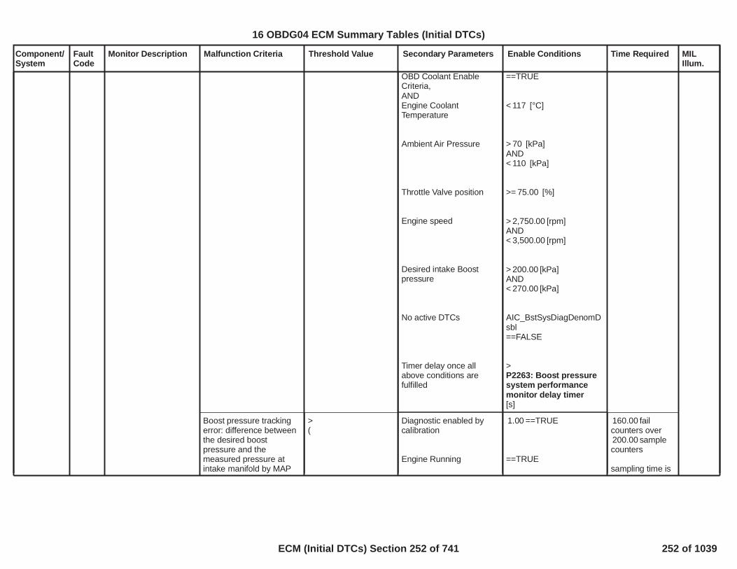
Component/System
FaultCode
Monitor Description Malfunction Criteria Threshold Value Secondary Parameters Enable Conditions Time Required MILIllum.
OBD Coolant EnableCriteria,ANDEngine CoolantTemperature
Ambient Air Pressure
Throttle Valve position
Engine speed
Desired intake Boostpressure
No active DTCs
Timer delay once allabove conditions arefulfilled
==TRUE
< [°C]117
> [kPa]70AND< [kPa]110
>= [%]75.00
> [rpm]2,750.00AND< [rpm]3,500.00
> [kPa]200.00AND< [kPa]270.00
AIC_BstSysDiagDenomDsbl==FALSE
>P2263: Boost pressuresystem performancemonitor delay timer[s]
Boost pressure trackingerror: difference betweenthe desired boostpressure and themeasured pressure atintake manifold by MAP
>(
Diagnostic enabled bycalibration
Engine Running
==TRUE1.00
==TRUE
fail160.00counters over
sample200.00counters
sampling time is
253
16 OBDG04 ECM Summary Tables (Initial DTCs)
ECM (Initial DTCs) Section 252 of 741 252 of 1039

Component/System
FaultCode
Monitor Description Malfunction Criteria Threshold Value Secondary Parameters Enable Conditions Time Required MILIllum.
sensor. P2263: Boostpressure systemperformance highthreshold (throttlecontrol active)[kPa]xP0234, P2263:Overboostbarometric correction)
OR
<(P2263: Boostpressure systemperformance lowthreshold (throttlecontrol active)[kPa]xP0299, P2263:Underboostbarometric correction)
Cranking ignition in range
Relay voltage in range
Difficult launch NOTdetected
Boost Pressure ControlClosed Loop active
No active transition fromone combustion mode toanother
Outside Air Temperature
Desired Boost Pressuresteady state:BstDes-BstDes_Old
Engine CoolantTemperatureOROBD Coolant EnableCriteria,ANDEngine CoolantTemperature
Battery voltage > 11.00[V]
Powertrain relay voltage >[V]11.00
Refer to"LDT_DifficultLaunchActive" Free Form
==TRUEAIC_BstCntrlCL
==TRUE
> [°C]-7.00AND< [°C]55.00
> [kPa/s]-18AND< [kPa/s]24
> [°C]70
==TRUE
< [°C]117
25ms
254
16 OBDG04 ECM Summary Tables (Initial DTCs)
ECM (Initial DTCs) Section 253 of 741 253 of 1039

Component/System
FaultCode
Monitor Description Malfunction Criteria Threshold Value Secondary Parameters Enable Conditions Time Required MILIllum.
Ambient Air Pressure
Throttle Valve position
Engine speed
Desired intake Boostpressure
No active DTCs
Timer delay once allabove conditions arefulfilled
> [kPa]70AND< [kPa]110
>= [%]100.00
> [rpm]2,750.00AND< [rpm]3,500.00
> [kPa]200.00AND< [kPa]270.00
AIC_BstSysDiagDenomDsbl==FALSE
>P2263: Boost pressuresystem performancemonitor delay timer[s]
255
16 OBDG04 ECM Summary Tables (Initial DTCs)
ECM (Initial DTCs) Section 254 of 741 254 of 1039

Component/System
FaultCode
Monitor Description Malfunction Criteria Threshold Value Secondary Parameters Enable Conditions Time Required MILIllum.
Water inFuel SensorCircuit
P2264 Water In Fuel signal = TRUE Powertrain relay voltage
No error for Engine NotRunning timer(refer toEngineModeNotRunTimerError
Ignition off time
Ignition on time
Test if Software andCalibration versionsmatch(refer to'MEMR FNA MatchedFlag' free form)
V11.0
= FALSE)
> s28,799.0
> s0.30< s1.80
failure out of10samples14
100 ms/sample
Type C,No SVS
256
16 OBDG04 ECM Summary Tables (Initial DTCs)
ECM (Initial DTCs) Section 255 of 741 255 of 1039

Component/System
FaultCode
Monitor Description Malfunction Criteria Threshold Value Secondary Parameters Enable Conditions Time Required MILIllum.
Difference (absolutevalue) in measuredpressure between BAROsensor and TCIAP sensor
AND
Difference (absolutevalue) in measuredpressure between TCIAPsensor and MAP sensor
AND
Difference (absolutevalue) in measuredpressure between BAROsensor and MAP sensor
>P0106, P2227, P227B,P00C7: Maximumpressure difference[kPa]
>P0106, P2227, P227B,P00C7: Maximumpressure difference[kPa]
<P0106, P2227, P227B,P00C7: Maximumpressure difference[kPa]
Correlation diagnosticenabled by calibration
Engine is running
Cranking ignition in range
Engine speed
Requested fuel
Throttle measuredposition
Engine CoolantTemperature
OR
OBD Coolant EnableCriteria
No faults are present
==TRUE1.00
==TRUE
Battery voltage >[V]11.00
< [rpm]1,100.00
< [mm^3]50.00
> [%]90.00
> [°C]70.00
==TRUE
CrankSensor_FA==FALSEFUL_GenericInjSysFA==FALSETPS_PstnSnsrFA==FALSEMAP_SensorCircuitFA==FALSEAAP2_SnsrCktFA==FALSEAAP_AAP5_SnsrCktFA==FALSE
fail320.00counters over
sample400.00counters
sampling time is12.5 ms
BarometricPressureSensor CCircuitRange/Performance
P227B This monitor is used toidentify TCIAP sensorinternal faults(measurement with anoffset or a drift).The plausibility monitorcompares the BARO,MAP and TCIAPpressures when theThrottle valve is open,the engine speed andthe fuel injectedquantity are below athreshold (engine idlecondition) and theengine coolanttemperature is higherthan a threshold: in thatcondition the threesensors are expectedto measure the samepressure. If TCIAPsensor drifts from theother two a specificDTC sets.
Type B,2 Trips
257
16 OBDG04 ECM Summary Tables (Initial DTCs)
ECM (Initial DTCs) Section 256 of 741 256 of 1039

Component/System
FaultCode
Monitor Description Malfunction Criteria Threshold Value Secondary Parameters Enable Conditions Time Required MILIllum.
AAP_AAP2_SnsrStabFA==FALSEAAP_AAP5_SnsrStabFA==FALSEECT_Sensor_FA==FALSEMAF_MAF_SnsrFA==FALSE
TCIAP Pressure
OR
TCIAP Pressure
< kPa50.0
> kPa115.0
Time between currentignition cycle and the lasttime the engine wasrunning
Engine is not rotating
No Active DTCs:
No Pending DTCs:
> seconds5.0
EngineModeNotRunTimerError
MAP_SensorCircuitFAAAP_SnsrCktFAAAP2_SnsrCktFAAAP3_SnsrCktFA
MAP_SensorCircuitFPAAP_SnsrCktFPAAP2_SnsrCktFPAAP3_SnsrCktFP
failures out of4samples5
1 sample every12.5 msec
258
16 OBDG04 ECM Summary Tables (Initial DTCs)
ECM (Initial DTCs) Section 257 of 741 257 of 1039

Component/System
FaultCode
Monitor Description Malfunction Criteria Threshold Value Secondary Parameters Enable Conditions Time Required MILIllum.
BarometricPressureSensorCircuit CLow (Diesel,pull-up)
P227C Detects a continuousshort to low in eitherthe signal circuit or theBARO C sensor.
BARO C Voltage < % of 5 Volt39.0Range
( Volts = kPa)2.0 49.7
failures out320of samples400
1 sample every12.5 msec
Type B,2 Trips
259
16 OBDG04 ECM Summary Tables (Initial DTCs)
ECM (Initial DTCs) Section 258 of 741 258 of 1039

Component/System
FaultCode
Monitor Description Malfunction Criteria Threshold Value Secondary Parameters Enable Conditions Time Required MILIllum.
BarometricPressureSensorCircuit CHigh (Diesel,pull-up)
P227D Detects an opensensor ground,continuous short tohigh or open in eitherthe signal circuit or theBARO C sensor.
BARO C Voltage > % of 5 Volt90.0Range
( Volts =4.5 115.0kPa)
failures out320of samples400
1 sample every12.5 msec
Type B,2 Trips
260
16 OBDG04 ECM Summary Tables (Initial DTCs)
ECM (Initial DTCs) Section 259 of 741 259 of 1039
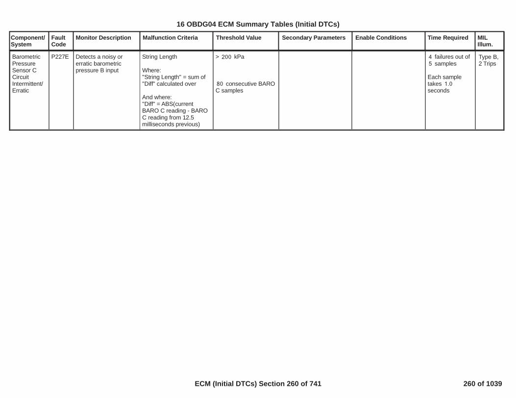
Component/System
FaultCode
Monitor Description Malfunction Criteria Threshold Value Secondary Parameters Enable Conditions Time Required MILIllum.
BarometricPressureSensor CCircuitIntermittent/Erratic
P227E Detects a noisy orerratic barometricpressure B input
String Length
Where:"String Length" = sum of"Diff" calculated over
And where:"Diff" = ABS(currentBARO C reading - BAROC reading from 12.5milliseconds previous)
> kPa200
consecutive BARO80C samples
failures out of4samples5
Each sampletakes 1.0seconds
Type B,2 Trips
261
16 OBDG04 ECM Summary Tables (Initial DTCs)
ECM (Initial DTCs) Section 260 of 741 260 of 1039

Component/System
FaultCode
Monitor Description Malfunction Criteria Threshold Value Secondary Parameters Enable Conditions Time Required MILIllum.
FuelPressureRegulator 1 -ForcedEngineShutdown
P228A Determine when railpressure is lower thandesired setpoint andpressure regulator 1has achieved itsmaximum authority.
Rail pressure setpoint -measured rail pressure
Commanded fuel flow formetering unit
> MPa40
Maximum fuel flowdeliverable by highpressure pump(refer to RailPresCntrlsection)
Run crank voltage
Engine running
Metering Unit controlled inclosed loop
No DTC active since keyis on:
V11.0
P000F
failures out640of samples800
12.5 ms/sample
Type A,1 Trips
262
16 OBDG04 ECM Summary Tables (Initial DTCs)
ECM (Initial DTCs) Section 261 of 741 261 of 1039

Component/System
FaultCode
Monitor Description Malfunction Criteria Threshold Value Secondary Parameters Enable Conditions Time Required MILIllum.
FuelPressureRegulator 2 -ForcedEngineShutdown
P228B Determine when railpressure is lower thandesired setpoint andpressure regulator 2has achieved itsmaximum authority.
Rail pressure setpoint -measured rail pressure
Commanded pressure forpressure regulator valve
> MPa40
P228B PressureRegulator completelyclosed command
Run crank voltage
Engine running
Pressure Regulatorcontrolled in closed loop
V11.0 failures out640of samples800
12.5 ms/sample
Type A,1 Trips
263
16 OBDG04 ECM Summary Tables (Initial DTCs)
ECM (Initial DTCs) Section 262 of 741 262 of 1039

Component/System
FaultCode
Monitor Description Malfunction Criteria Threshold Value Secondary Parameters Enable Conditions Time Required MILIllum.
Rail pressure setpoint -measured rail pressure
Fuel injected quantity
>P228C Positive railpressure deviation(MU)
> mm^3/stroke3.0
Run crank voltage
Engine running
Metering Unit controlled inclosed loop
(P228C P228D Low fuellevel calibrated asenabling condition (MU)
ANDLowFuelConditionDiagnostic
(P228C P228D Airambient pressurecalibrated as enablingcondition (MU)AND
Air ambient pressure
(P228C P228D Airambient temperaturecalibrated as enablingcondition (MU)AND
Air ambient temperature
No DTC active since keyis on:
V11.0
= FALSE)
kPa)60
°C)-7
P000F
failures out640of samples800
12.5 ms/sample
MIL is illuminatedaccording to'similar engineconditions'criteria.
FuelPressureRegulator 1ExceededControlLimits -Pressure TooLow(Commondebouncer)
P228C Determine when railpressure is lower thandesired setpoint.
Type B,2 Trips
Rail pressure setpoint -measured rail pressure
Fuel injected quantity
>P229A Positive railpressure deviation(PR)
> mm^3/stroke3.0
Run crank voltage
Engine running
Pressure Regulatorcontrolled in closed loop
V11.0 failures out640of
samples800
12.5 ms/sample
MIL is illuminatedaccording to
264
16 OBDG04 ECM Summary Tables (Initial DTCs)
ECM (Initial DTCs) Section 263 of 741 263 of 1039

Component/System
FaultCode
Monitor Description Malfunction Criteria Threshold Value Secondary Parameters Enable Conditions Time Required MILIllum.
(
P229A P229B Low fuellevel calibrated asenabling condition (PR)AND
LowFuelConditionDiagnostic
(P229A P229B Airambient pressurecalibrated as enablingcondition (PR)AND
Air ambient pressure
(P229A P229B Airambient temperaturecalibrated as enablingcondition (PR)AND
Air ambient temperature
= FALSE)
kPa)60
°C)-7
'similar engineconditions'criteria.
265
16 OBDG04 ECM Summary Tables (Initial DTCs)
ECM (Initial DTCs) Section 264 of 741 264 of 1039

Component/System
FaultCode
Monitor Description Malfunction Criteria Threshold Value Secondary Parameters Enable Conditions Time Required MILIllum.
Rail pressure setpoint -measured rail pressure
Fuel injected quantity
Fuel temperature
<P228D Negative railpressure deviation(MU)
> mm^3/stroke3.0
> °C-40
Run crank voltage
Engine running
Metering Unit controlled inclosed loop
(P228C P228D Low fuellevel calibrated asenabling condition (MU)
ANDLowFuelConditionDiagnostic
(P228C P228D Airambient pressurecalibrated as enablingcondition (MU)AND
Air ambient pressure
(P228C P228D Airambient temperaturecalibrated as enablingcondition (MU)AND
Air ambient temperature
No DTC active since keyis on:
V11.0
= FALSE)
kPa)60
°C)-7
P000F
failures out640of
samples800
12.5 ms/sample
MIL is illuminatedaccording to'similar engineconditions'criteria.
FuelPressureRegulator 1ExceededControlLimits -Pressure TooHigh(Commondebouncer)
P228D Determine when railpressure is higher thandesired setpoint.
Type B,2 Trips
Rail pressure setpoint -measured rail pressure
Fuel injected quantity
< MPa-15
> mm^3/stroke3.0
Run crank voltage
Engine running
Pressure Regulatorcontrolled in closed loop
V11.0 failures out640of
samples800
12.5 ms/sample
MIL is illuminatedaccording to
16 OBDG04 ECM Summary Tables (Initial DTCs)
ECM (Initial DTCs) Section 265 of 741 265 of 1039

Component/System
FaultCode
Monitor Description Malfunction Criteria Threshold Value Secondary Parameters Enable Conditions Time Required MILIllum.
(
P229A P229B Low fuellevel calibrated asenabling condition (PR)AND
LowFuelConditionDiagnostic
(P229A P229B Airambient pressurecalibrated as enablingcondition (PR)AND
Air ambient pressure
(P229A P229B Airambient temperaturecalibrated as enablingcondition (PR)AND
Air ambient temperature
= FALSE)
kPa)60
°C)-7
'similar engineconditions'criteria.
16 OBDG04 ECM Summary Tables (Initial DTCs)
ECM (Initial DTCs) Section 266 of 741 266 of 1039

Component/System
FaultCode
Monitor Description Malfunction Criteria Threshold Value Secondary Parameters Enable Conditions Time Required MILIllum.
FuelPressureRegulator 2Performance
P2293 Determine when railpressure is abovemaximum thresholdwhen pressure isgoverned by PressureRegulator valve.
Rail pressure >P2293 Maximum railpressure with PR
Run crank voltage
Rail pressure is governedby Pressure Regulator
V11.0 failures out160of
samples229
OR
continuous160failures out of229samples
6.25 ms/sample
Type A,1 Trips
268
16 OBDG04 ECM Summary Tables (Initial DTCs)
ECM (Initial DTCs) Section 267 of 741 267 of 1039

Component/System
FaultCode
Monitor Description Malfunction Criteria Threshold Value Secondary Parameters Enable Conditions Time Required MILIllum.
FuelPressureRegulator 2ControlCircuit
P2294 Determine when anopen circuit affectsFuel PressureRegulator 2 (PressureRegulator Valve)control circuit.
Impedence betweensignal and controllerground 200 k
Powertrain relay voltage
Run crank voltage
Engine not cranking
Pressure RegulatorValve present
V11.0
> V6.0
failures out of44samples88
6.25 ms/sample
Type A,1 Trips
269
16 OBDG04 ECM Summary Tables (Initial DTCs)
ECM (Initial DTCs) Section 268 of 741 268 of 1039

Component/System
FaultCode
Monitor Description Malfunction Criteria Threshold Value Secondary Parameters Enable Conditions Time Required MILIllum.
FuelPressureRegulatorSolenoid 2ControlCircuit LowVoltage
P2295 Determine when shortcircuit to ground affectsFuel PressureRegulator 2 (PressureRegulator Valve)control circuit.
Impedence betweensignal and controllerground 0.5
Powertrain relay voltage
Run crank voltage
Engine not cranking
Pressure RegulatorValve present
V11.0
> V6.0
failures out of44samples88
6.25 ms/sample
Type A,1 Trips
270
16 OBDG04 ECM Summary Tables (Initial DTCs)
ECM (Initial DTCs) Section 269 of 741 269 of 1039

Component/System
FaultCode
Monitor Description Malfunction Criteria Threshold Value Secondary Parameters Enable Conditions Time Required MILIllum.
FuelPressureRegulatorSolenoid 2ControlCircuit HighVoltage
P2296 Determine when shortcircuit to power affectsFuel PressureRegulator 2 (PressureRegulator Valve)control circuit.
Impedence betweensignal and controllerpower 0.5
Powertrain relay voltage
Run crank voltage
Engine not cranking
Pressure RegulatorValve present
V11.0
> V6.0
failures out of44samples88
6.25 ms/sample
Type A,1 Trips
271
16 OBDG04 ECM Summary Tables (Initial DTCs)
ECM (Initial DTCs) Section 270 of 741 270 of 1039

Component/System
FaultCode
Monitor Description Malfunction Criteria Threshold Value Secondary Parameters Enable Conditions Time Required MILIllum.
Closed LoopReductantInjectionControl AtLimit - FlowToo Low
P249D This diagnosis checksif the DEF injectionsystem has exceededlimit of correctionauthority
Monitoring is executedby compararing LongTerm Adaptation Factor(LTAF) with acalibratable threshold:LTAF > OBD HighThreshold
The longtermadaptation factor iscreated based on theinformation given bythe NH3 storagecorrection strategy, thisfactor represents thedeviation of thecomplete SCR systemmeasured and shall beused to compensate itby making a correctionover the DEF injectionquantity
Long Term AdaptationFactor (LTAF) higher thancalibrateable Threshold
LTAF > 1.69 Test enabled bycalibration;
CalOut = [Boolean];1 One failure to setthe DTC
Type B,2 Trips
272
16 OBDG04 ECM Summary Tables (Initial DTCs)
ECM (Initial DTCs) Section 271 of 741 271 of 1039

Component/System
FaultCode
Monitor Description Malfunction Criteria Threshold Value Secondary Parameters Enable Conditions Time Required MILIllum.
Closed LoopReductantInjectionControl AtLimit - FlowToo High
P249E This diagnosis checksif the DEF injectionsystem has exceededlimit of correctionauthority
Monitoring is executedby compararing LongTerm Adaptation Factor(LTAF) with acalibratable threshold:LTAF < OBD LowThreshold
The longtermadaptation factor iscreated based on theinformation given bythe NH3 storagecorrection strategy, thisfactor represents thedeviation of thecomplete SCR systemmeasured and shall beused to compensate itby making a correctionover the DEF injectionquantity
Long Term AdaptationFactor (LTAF) lower thancalibrateable Threshold
LTAF < 0.41 Test enabled bycalibration;
CalOut = [Boolean];1 One failure to setthe DTC
Type B,2 Trips
273
16 OBDG04 ECM Summary Tables (Initial DTCs)
ECM (Initial DTCs) Section 272 of 741 272 of 1039

Component/System
FaultCode
Monitor Description Malfunction Criteria Threshold Value Secondary Parameters Enable Conditions Time Required MILIllum.
Transmission ControlTorqueRequestCircuit
P2544 Determines if thetorque request from theTCM is valid
Protection error - SerialCommunication message2’s complement not equal($189/$199)
ORRolling count error - SerialCommunication message($189/$199) rolling countindex value
ORRange Error - SerialCommunication message- ($189/$199) TCMRequested TorqueIncrease
ORMulti-transition error -Trans torque interventiontype request change
Message <> two'scomplement ofmessage
Message <> previousmessage rolling countvalue + one
> Nm500
Requested torqueintervention typetoggles from anincreasing request tonot an increasingrequest then back toan increasing requestwithin 200ms
Diagnostic Status
Power Mode
Ignition Voltage
Engine Running
Run/Crank Active
No Serial communicationloss to TCM (U0101)
Enabled
= Run
> volts6.41
= True
> Sec0.50
No loss ofcommunication
>= protection16value errorsout of
samples.20
Performed onevery receivedmessage
>= Rolling6count errors outof 10 samples.
Performed onevery receivedmessage
>= range6errors out of10 samples.
Performed onevery receivedmessage
>= multi-3transitions errorsout of 5 samples.
Performed every200 msec
Type B,2 Trips
274
16 OBDG04 ECM Summary Tables (Initial DTCs)
ECM (Initial DTCs) Section 273 of 741 273 of 1039

Component/System
FaultCode
Monitor Description Malfunction Criteria Threshold Value Secondary Parameters Enable Conditions Time Required MILIllum.
PerformanceTractionTorque &SpeedRequestCircuit
P2548 Determines if torqueand/or speed requestfrom the EBTCM isvalid
Protection error - SerialCommunication message($1C8) 2’s complementnot equal
Engine Torque Request
Engine Speed Request
ORRolling count error - SerialCommunication message($1C8) rolling count indexvalue
Message <> two'scomplement ofmessage
Message <> two'scomplement ofmessage
Message <> previousmessage rolling countvalue + one
Diagnostic Status
Run/Crank Active
Ignition Voltage
No Serial communicationloss to EBTCM (U0121)
Enabled
> seconds0.50
> volts6.41
No loss of communication
Fail Threshold:>= errors10out of
samples20
Pass Threshold:>= samples10during key cycle.
ORFail Threshold>= 6Rolling counterrors out of10 samples
Performed onevery receivedmessage
Type B,2 Trips
275
16 OBDG04 ECM Summary Tables (Initial DTCs)
ECM (Initial DTCs) Section 274 of 741 274 of 1039

Component/System
FaultCode
Monitor Description Malfunction Criteria Threshold Value Secondary Parameters Enable Conditions Time Required MILIllum.
Engine Speed exceeds athreshold for a period oftime
Fail Condition:
Engine Speed> RPM5,000
Engine Speed> RPM1,500
Fail threshold:
Overspeedcondition TRUE> seconds25.0
UnmeteredFuel -ForcedEngineShutdown
P25BD Determines if engineoverspeed condition isoccuring when no fuelis being delivered
Type A,1 Trips
Engine Speed less than athreshold for a period oftime
Pass Condition:
Engine Speed< ( - ) RPM5,000 300
Engine Speed> RPM1,500
Pass threshold:
Overspeedcondition FALSE> seconds25.0
276
16 OBDG04 ECM Summary Tables (Initial DTCs)
ECM (Initial DTCs) Section 275 of 741 275 of 1039

Component/System
FaultCode
Monitor Description Malfunction Criteria Threshold Value Secondary Parameters Enable Conditions Time Required MILIllum.
ControlModulePower OffTimerPerformance
P262B This DTC determines ifthe hardware timerdoes not initialize orcount properly. Thereare two tests to ensureproper functioning ofthe timer: Count UpTest (CUT) and RangeTest (RaTe).
Count Up Test (CUT):Verifies that the HWIOtimer is counting upwith the properincrement.
Range Test (RaTe):When the run/crank isnot active both thehardware and mirrortimers are started. Thetimers are comparedwhen module shutdownis initiated or run/crankbecomes active.
Count Up Test:
Time difference betweenthe current read and theprevious read of the timer
Range Test:
The variation of the HWIOtimer and mirror timer is
> seconds1.50
> %.0.25
Count Up Test:failures out of4samples20
1 sec / sample
Continuous whilerun/crank is notactive and untilcontrollershutdown isinitiated.
Range Test:Once per tripwhen controllershutdown isinitiated or run/crank becomesactive.
Type B,2 Trips
277
16 OBDG04 ECM Summary Tables (Initial DTCs)
ECM (Initial DTCs) Section 276 of 741 276 of 1039

Component/System
FaultCode
Monitor Description Malfunction Criteria Threshold Value Secondary Parameters Enable Conditions Time Required MILIllum.
MalfunctionIndicatorLamp (MIL)ControlCircuit(ODM) Low
P263A Diagnoses themalfunction indicatorlamp control low sidedriver circuit for circuitfaults.
Voltage low during driveroff state (indicates short-to-ground)
Short to ground: 0.5 impedance
between signal andcontroller ground
Run/Crank Voltage
Remote Vehicle Start isnot active
Voltage volts11.00 failures out of1samples1
50 ms / sample
Type B,No MIL
NO MIL
Note: Incertaincontrollers P0650may alsoset (MILControlOpenCircuit)
278
16 OBDG04 ECM Summary Tables (Initial DTCs)
ECM (Initial DTCs) Section 277 of 741 277 of 1039

Component/System
FaultCode
Monitor Description Malfunction Criteria Threshold Value Secondary Parameters Enable Conditions Time Required MILIllum.
MalfunctionIndicatorLamp (MIL)ControlCircuit(ODM) High
P263B Diagnoses themalfunction indicatorlamp control low sidedriver circuit for circuitfaults.
Voltage high during driveron state (indicates shortto power)
Short to power: 0.5 impedance
between signal andcontroller power
Run/Crank Voltage
Remote Vehicle Start isnot active
Voltage volts11.00 failures out of4samples5
50 ms / sample
Type B,No MIL
NO MIL
279
16 OBDG04 ECM Summary Tables (Initial DTCs)
ECM (Initial DTCs) Section 278 of 741 278 of 1039

Component/System
FaultCode
Monitor Description Malfunction Criteria Threshold Value Secondary Parameters Enable Conditions Time Required MILIllum.
Shared HighSide Drive#2 ControlCircuit Low(STG) -(GEN IIIControllersONLY)
P2670 Diagnoses shared highside driver circuit lowvoltage
Shared high side drive #2control circuit low voltage
Controller internaldiagnostic
Shared high side drive #2low diag enable
Powertrain relay voltage
Run Crank voltage
Powertrain relay state
= 1.00
>= 11.00
> 6.00
= ON
failures out of20samples25
100 ms / sample
Type B,2 Trips
280
16 OBDG04 ECM Summary Tables (Initial DTCs)
ECM (Initial DTCs) Section 279 of 741 279 of 1039

Component/System
FaultCode
Monitor Description Malfunction Criteria Threshold Value Secondary Parameters Enable Conditions Time Required MILIllum.
Shared HighSide Drive#2 ControlCircuit High(STP) -(GEN IIIControllersONLY)
P2671 Diagnoses shared highside driver circuit highvoltage
Shared high side drive #2control circuit high voltage
Controller internaldiagnostic
Shared high side drive #2diag enable
Powertrain relay voltage
Run Crank voltage
Powertrain relay state
= 1.00
>= 11.00
> 6.00
= ON
failures out of20samples25
100 ms / sample
Type B,2 Trips
281
16 OBDG04 ECM Summary Tables (Initial DTCs)
ECM (Initial DTCs) Section 280 of 741 280 of 1039

Component/System
FaultCode
Monitor Description Malfunction Criteria Threshold Value Secondary Parameters Enable Conditions Time Required MILIllum.
Fuel SupplyHeaterControlCircuit/Open
P2687 Determine when anopen circuit affectsFuel Supply Heatercontrol circuit.
Impedence betweensignal and controllerground 200 k
Run crank voltage
Powertrain relay voltage
Engine not cranking
> V6.0
V11.0
failures out of10samples20
100 ms/sample
Type C,No SVS
282
16 OBDG04 ECM Summary Tables (Initial DTCs)
ECM (Initial DTCs) Section 281 of 741 281 of 1039

Component/System
FaultCode
Monitor Description Malfunction Criteria Threshold Value Secondary Parameters Enable Conditions Time Required MILIllum.
Fuel SupplyHeaterControlCircuit Low
P2688 Determine when shortcircuit to ground affectsFuel Supply Heatercontrol circuit.
Impedence betweensignal and controllerground 0.5
Run crank voltage
Powertrain relay voltage
Engine not cranking
> V6.0
V11.0
failures out of10samples20
100 ms/sample
Type C,No SVS
283
16 OBDG04 ECM Summary Tables (Initial DTCs)
ECM (Initial DTCs) Section 282 of 741 282 of 1039

Component/System
FaultCode
Monitor Description Malfunction Criteria Threshold Value Secondary Parameters Enable Conditions Time Required MILIllum.
Fuel SupplyHeaterControlCircuit High
P2689 Determine when shortcircuit to power affectsFuel Supply Heatercontrol circuit.
Impedence betweensignal and controllerpower 0.5
Run crank voltage
Powertrain relay voltage
Engine not cranking
> V6.0
V11.0
failures out of10samples20
100 ms/sample
Type C,No SVS
284
16 OBDG04 ECM Summary Tables (Initial DTCs)
ECM (Initial DTCs) Section 283 of 741 283 of 1039

Component/System
FaultCode
Monitor Description Malfunction Criteria Threshold Value Secondary Parameters Enable Conditions Time Required MILIllum.
Four WheelDrive LowSwitchCircuit
P2771 Fail Case 1:Continuous Open(Stuck Off) in the FourWheel Drive LowSwitch CircuitFail Case2: Ground (Stuck On)in the Four Wheel DriveLow Switch Circuit
4WD Low SwitchTransfer case gear ratio
4WD Low SwitchTransfer case gear ratio
= TRUEand5.700 8.000
= FALSEand0.700 1.550
Engine Torque
Engine Speed
Ignition voltage
Throttle position
TransmissionTemperature
Engine Run time
Vehicle Speed
TPS_FAVehicleSpeedSensor_FA
EngineTorqureInaccurate
Transmission gear
P0502, P0503, P0722,P0723, P215C, P2160,P2161, U0101
Clutch
Transmission Input SpeedSignal
N-M 30.0 8,191.8
RPM 1,000 5,500
Volts 9.0 32.00
% 3.0 99.0
ºC -40.0 130.0
>= Sec10.0
>= Mph5.00
FalseFalse
FALSE
Not in Park, Reverse, orNeutral
Not Fault Active
Engaged (Manualtransmission only)
Valid (Automatictransmission only)
2.0sec7.0sec
Type B,2 Trips
285
16 OBDG04 ECM Summary Tables (Initial DTCs)
ECM (Initial DTCs) Section 284 of 741 284 of 1039

Component/System
FaultCode
Monitor Description Malfunction Criteria Threshold Value Secondary Parameters Enable Conditions Time Required MILIllum.
TransferCase ControlModuleTransferCaseCommandStateRationality -4wd highcommandnot 4wd highratio
P279A Monitor measurestransfer case gear ratiois 4wd low ratio orneutral ratio while thetransfer case controlmodule command stateis 4wd high.
measured transfer caseratio is 4wd high ratioANDmeasured transfer caseratio calculation updated
(measured transfer caseratio = transmissionoutput speed / transfercase output speed)
= FALSE
= TRUE
transfer case contolmodule transfer casecommand state
weighted fail count
measured transfer caseratio is 4wd high ratio setto TRUEANDmeasured tranfer caseratio calculation updatedset to TRUE
transfer case outputspeed sensorconfiguration =CeFWDD_e_UseTCSS
= 4wd high
=P279A P279B P279CTransfer Case ControlModule Transfer CaseCommand StateRationality (weightingfactor)(see supproting table)
measured transfer caseratio >=P279A Transfer CaseControl Module TransferCase Command StateRationality (margin oferror low)(see supporting table)ANDmeasured transfer caseratio <=P279A Transfer CaseControl Module TransferCase Command StateRationality (margin oferror high)(see supporting table)
transfer case outputspeed sensorconfiguration =CeFWDD_e_UseTCSS
= FALSE
weighted failcount >= out of5sample count >=280(12.5milleseconds percount)
Type B,2 Trips
16 OBDG04 ECM Summary Tables (Initial DTCs)
ECM (Initial DTCs) Section 285 of 741 285 of 1039

Component/System
FaultCode
Monitor Description Malfunction Criteria Threshold Value Secondary Parameters Enable Conditions Time Required MILIllum.
P0502 fault activeANDP0503 fault activeANDP0722 fault activeANDP0723 fault activeANDP2160 fault activeANDP2616 fault active
vehicle drive wheel typeconfigurationNOTCeFWDG_e_No_AWD_Or_FWDAND NOTCeFWDG_e_Versatrak_AWDAND NOTCeFWDG_e_FWD_AWD_SingleSpd
= FALSE
= FALSE
= FALSE
= FALSE
= FALSE
vehicle drive wheel typeconfiguration =CeFWDR_e_FWD_ECM_TCM_TCCM
16 OBDG04 ECM Summary Tables (Initial DTCs)
ECM (Initial DTCs) Section 286 of 741 286 of 1039

Component/System
FaultCode
Monitor Description Malfunction Criteria Threshold Value Secondary Parameters Enable Conditions Time Required MILIllum.
TransferCase ControlModuleTransferCaseCommandStateRationality -4wd lowcommandnot 4wd lowratio
P279B Monitor measurestransfer case gear ratiois 4wd high ratio orneutral ratio while thetransfer case controlmodule command stateis 4wd low.
measured transfer caseratio is 4wd low ratioANDmeasured transfer caseratio calculation updated
(measured transfer caseratio = transmissionoutput speed / transfercase output speed)
= FALSE
= TRUE
transfer case contolmodule transfer casecommand state
weighted fail count
measured transfer caseratio is 4wd low ratio setto TRUEANDmeasured tranfer caseratio calculation updatedset to TRUE
transfer case outputspeed sensorconfiguration =CeFWDD_e_UseTCSS
= 4wd low
=P279A P279B P279CTransfer Case ControlModule Transfer CaseCommand StateRationality (weightingfactor)(see supproting table)
measured transfer caseratio >=P279A Transfer CaseControl Module TransferCase Command StateRationality (margin oferror low)(see supporting table)ANDmeasured transfer caseratio <=P279A Transfer CaseControl Module TransferCase Command StateRationality (margin oferror high)(see supporting table)
transfer case outputspeed sensorconfiguration =CeFWDD_e_UseTCSS
= FALSE
weighted failcount >= out of5sample count >=280(12.5milleseconds percount)
Type B,2 Trips
288
16 OBDG04 ECM Summary Tables (Initial DTCs)
ECM (Initial DTCs) Section 287 of 741 287 of 1039

Component/System
FaultCode
Monitor Description Malfunction Criteria Threshold Value Secondary Parameters Enable Conditions Time Required MILIllum.
P0502 fault activeANDP0503 fault activeANDP0722 fault activeANDP0723 fault activeANDP2160 fault activeANDP2616 fault active
vehicle drive wheel typeconfigurationNOTCeFWDG_e_No_AWD_Or_FWDAND NOTCeFWDG_e_Versatrak_AWDAND NOTCeFWDG_e_FWD_AWD_SingleSpd
= FALSE
= FALSE
= FALSE
= FALSE
= FALSE
vehicle drive wheel typeconfiguration =CeFWDR_e_FWD_ECM_TCM_TCCM
289
16 OBDG04 ECM Summary Tables (Initial DTCs)
ECM (Initial DTCs) Section 288 of 741 288 of 1039

Component/System
FaultCode
Monitor Description Malfunction Criteria Threshold Value Secondary Parameters Enable Conditions Time Required MILIllum.
TransferCase ControlModuleTransferCaseCommandStateRationality -4wd neutralcommandnot 4wdneutral ratio
P279C Monitor measurestransfer case gear ratiois 4wd high ratio or 4wdlow ratio while thetransfer case controlmodule command stateis 4wd neutral.
measured transfer caseratio is 4wd neutral ratioANDmeasured transfer caseratio calculation updated
(measured transfer caseratio = transmissionoutput speed / transfercase output speed)
= FALSE
= TRUE
transfer case contolmodule transfer casecommand state
weighted fail count
measured transfer caseratio is 4wd neutral ratioset to TRUEANDmeasured tranfer caseratio calculation updatedset to TRUEwhenratio check 1ANDratio check 2
= 4wd neutral
=P279A P279B P279CTransfer Case ControlModule Transfer CaseCommand StateRationality (weightingfactor)(see supproting table)
ratio check 1:measured transfer caseratio >=P279C Transfer CaseControl Module TransferCase Command StateRationality (margin oferror high 1)(see supporting table)ORmeasured transfer caseratio <=P279C Transfer CaseControl Module TransferCase Command StateRationality (margin oferror low 1)
ratio check 2measured transfer caseratio >=
weighted failcount >= out of5sample count >=280(12.5milleseconds percount)
Type A,1 Trips
290
16 OBDG04 ECM Summary Tables (Initial DTCs)
ECM (Initial DTCs) Section 289 of 741 289 of 1039

Component/System
FaultCode
Monitor Description Malfunction Criteria Threshold Value Secondary Parameters Enable Conditions Time Required MILIllum.
transfer case outputspeed sensorconfiguration =CeFWDD_e_UseTCSS
P0502 fault activeANDP0503 fault activeANDP0722 fault activeANDP0723 fault activeANDP2160 fault activeANDP2616 fault active
vehicle drive wheel typeconfigurationNOTCeFWDG_e_No_AWD_Or_FWDAND NOTCeFWDG_e_Versatrak_AWDAND NOTCeFWDG_e_FWD_AWD_SingleSpd
P279C Transfer CaseControl Module TransferCase Command StateRationality (margin oferror high 2)(see supporting table)ORmeasured transfer caseratio <=P279C Transfer CaseControl Module TransferCase Command StateRationality (margin oferror low 2)
transfer case outputspeed sensorconfiguration =CeFWDD_e_UseTCSS
= FALSE
= FALSE
= FALSE
= FALSE
= FALSE
= FALSE
vehicle drive wheel typeconfiguration =CeFWDR_e_FWD_ECM_TCM_TCCM
291
16 OBDG04 ECM Summary Tables (Initial DTCs)
ECM (Initial DTCs) Section 290 of 741 290 of 1039

Component/System
FaultCode
Monitor Description Malfunction Criteria Threshold Value Secondary Parameters Enable Conditions Time Required MILIllum.
neutral rationality enabled
= 1
292
16 OBDG04 ECM Summary Tables (Initial DTCs)
ECM (Initial DTCs) Section 291 of 741 291 of 1039

Component/System
FaultCode
Monitor Description Malfunction Criteria Threshold Value Secondary Parameters Enable Conditions Time Required MILIllum.
ControlModuleCommunication Bus A Off
U0073 This DTC monitors fora BUS A off condition
Bus off failures exceeds
before the sample time ofis reached
counts5(equivalent to 0.06seconds)
seconds0.56
General Enable Criteria:
U0073
Normal CAN transmissionon Bus A
Device Control
High Voltage VirtualNetwork Management
Ignition Voltage Criteria:
Run/Crank Ignitionvoltage
Power Mode
Off Cycle Enable Criteria:
KeCAND_b_OffKeyCycleDiagEnbl
Ignition Accessory LineandBattery Voltage
General Enable Criteriaand either Ignition VoltageCriteria or Off CycleEnable Criteria met for >
seconds3.0000
CAN hardware is busOFF for
Not Active on Current KeyCycle
Enabled
Not Active
Not Active
> Volts6.41
= run
= 1( 1 indicates enabled)
= Active
> Volts11.00
> seconds0.1125
Diagnostic runsin 12.5 ms loop
Type A,1 Trips
293
16 OBDG04 ECM Summary Tables (Initial DTCs)
ECM (Initial DTCs) Section 292 of 741 292 of 1039

Component/System
FaultCode
Monitor Description Malfunction Criteria Threshold Value Secondary Parameters Enable Conditions Time Required MILIllum.
ControlModuleCommunication Bus B Off
U0074 This DTC monitors fora BUS B off condition
Bus off failures exceeds
before the sample time ofis reached
counts5(equivalent to 0.06seconds)
seconds0.56
General Enable Criteria:
U0074
Normal CAN transmissionon Bus B
Device Control
High Voltage VirtualNetwork Management
Ignition Voltage Criteria:
Run/Crank Ignitionvoltage
Power Mode
Off Cycle Enable Criteria:
KeCAND_b_OffKeyCycleDiagEnbl
Ignition Accessory LineandBattery Voltage
General Enable Criteriaand either Ignition VoltageCriteria or Off CycleEnable Criteria met for >
seconds3.0000
CAN hardware is busOFF for
Not Active on Current KeyCycle
Enabled
Not Active
Not Active
> Volts6.41
= run
= 1(1 indicates enabled)
= Active
> Volts11.00
> seconds0.1125
Diagnostic runsin 12.5 ms loop
Type A,1 Trips
294
16 OBDG04 ECM Summary Tables (Initial DTCs)
ECM (Initial DTCs) Section 293 of 741 293 of 1039

Component/System
FaultCode
Monitor Description Malfunction Criteria Threshold Value Secondary Parameters Enable Conditions Time Required MILIllum.
LostCommunication With TCM
U0101 This DTC monitors fora loss ofcommunication with thetransmission controlmodule
Message is not receivedfrom controller for
Message $0BD
Message $0C7
Message $0F9
Message $189
Message $199
Message $19D
Message $1AF
Message $1F5
Message $4C9
seconds10.0
seconds10.0
seconds10.0
seconds10.0
seconds10.0
seconds10.0
seconds10.0
seconds10.0
seconds10.0
General Enable Criteria:
U0073
Normal CAN transmissionon Bus A
Device Control
High Voltage VirtualNetwork Management
Ignition Voltage Criteria:
Run/Crank Ignitionvoltage
Power Mode
Off Cycle Enable Criteria:
KeCAND_b_OffKeyCycleDiagEnbl
Ignition Accessory LineandBattery Voltage
General Enable Criteriaand either Ignition VoltageCriteria or Off CycleEnable Criteria met for >
seconds3.0000
Power Mode is inaccessory or run or crankand High Voltage VirtualNetwork Management is
Not Active on Current KeyCycle
Enabled
Not Active
Not Active
> Volts6.41
= run
= 1(1 indicates enabled)
= Active
> Volts11.00
Diagnostic runsin 12.5 ms loop
Type B,2 Trips
295
16 OBDG04 ECM Summary Tables (Initial DTCs)
ECM (Initial DTCs) Section 294 of 741 294 of 1039

Component/System
FaultCode
Monitor Description Malfunction Criteria Threshold Value Secondary Parameters Enable Conditions Time Required MILIllum.
not active for
U0101
TCM
> seconds0.4000
Not Active on Current KeyCycle
is present on the bus
296
16 OBDG04 ECM Summary Tables (Initial DTCs)
ECM (Initial DTCs) Section 295 of 741 295 of 1039

Component/System
FaultCode
Monitor Description Malfunction Criteria Threshold Value Secondary Parameters Enable Conditions Time Required MILIllum.
LostCommunication WithTransferCase ControlModule
U0102 This DTC monitors fora loss ofcommunication with thetransfer case controlmodule
Message is not receivedfrom controller for
Message $1CB
Message $1CC
seconds10.0
seconds10.0
General Enable Criteria:
U0073
Normal CAN transmissionon Bus A
Device Control
High Voltage VirtualNetwork Management
Ignition Voltage Criteria:
Run/Crank Ignitionvoltage
Power Mode
Off Cycle Enable Criteria:
KeCAND_b_OffKeyCycleDiagEnbl
Ignition Accessory LineandBattery Voltage
General Enable Criteriaand either Ignition VoltageCriteria or Off CycleEnable Criteria met for >
seconds3.0000
Power Mode is inaccessory or run or crankand High Voltage VirtualNetwork Management is
Not Active on Current KeyCycle
Enabled
Not Active
Not Active
> Volts6.41
= run
= 1(1 indicates enabled)
= Active
> Volts11.00
Diagnostic runsin 12.5 ms loop
Type B,2 Trips"SpecialType C"
297
16 OBDG04 ECM Summary Tables (Initial DTCs)
ECM (Initial DTCs) Section 296 of 741 296 of 1039

Component/System
FaultCode
Monitor Description Malfunction Criteria Threshold Value Secondary Parameters Enable Conditions Time Required MILIllum.
not active for
U0102
TCCM
> seconds0.4000
Not Active on Current KeyCycle
is present on the bus
298
16 OBDG04 ECM Summary Tables (Initial DTCs)
ECM (Initial DTCs) Section 297 of 741 297 of 1039

Component/System
FaultCode
Monitor Description Malfunction Criteria Threshold Value Secondary Parameters Enable Conditions Time Required MILIllum.
LostCommunication WithReductantControlModule(SCR)
U010E This DTC monitors fora loss ofcommunication with theReductant ControlModule (SCR)
Message is not receivedfrom controller for
Message $092
Message $4CC
Message $4CD
Message $4E5
Message $4E6
Message $4E7
Message $4E8
Message $4E9
seconds10.00
seconds10.00
seconds10.00
seconds10.00
seconds10.00
seconds10.00
seconds10.00
seconds10.00
General Enable Criteria:
U0074
Normal CAN transmissionon Bus B
Device Control
High Voltage VirtualNetwork Management
Ignition Voltage Criteria:
Run/Crank Ignitionvoltage
Power Mode
Off Cycle Enable Criteria:
KeCAND_b_OffKeyCycleDiagEnbl
Ignition Accessory LineandBattery Voltage
General Enable Criteriaand either Ignition VoltageCriteria or Off CycleEnable Criteria met for >
seconds3.0000
Power Mode is inaccessory or run or crankand High Voltage VirtualNetwork Management is
Not Active on Current KeyCycle
Enabled
Not Active
Not Active
> Volts6.41
= run
= 1(1 indicates enabled)
= Active
> Volts11.00
Diagnostic runsin 12.5 ms loop
Type A,1 Trips
299
16 OBDG04 ECM Summary Tables (Initial DTCs)
ECM (Initial DTCs) Section 298 of 741 298 of 1039

Component/System
FaultCode
Monitor Description Malfunction Criteria Threshold Value Secondary Parameters Enable Conditions Time Required MILIllum.
not active for
U010E
Reductant Control Module
> seconds0.4000
Not Active on Current KeyCycle
is present on the bus
300
16 OBDG04 ECM Summary Tables (Initial DTCs)
ECM (Initial DTCs) Section 299 of 741 299 of 1039

Component/System
FaultCode
Monitor Description Malfunction Criteria Threshold Value Secondary Parameters Enable Conditions Time Required MILIllum.
LostCommunication With Anti-Lock BrakeSystem(ABS)ControlModule
U0121 This DTC monitors fora loss ofcommunication with theAnti-Lock BrakeSystem (ABS) ControlModule (Non-OBDModule ID 243).
Message is not receivedfrom controller for
Message $0C1
Message $0C5
Message $1C7
Message $1E9
Message $2F1
Message $2F9
seconds10.0
seconds10.0
seconds10.0
seconds10.0
seconds10.0
seconds10.0
General Enable Criteria:
U0073
Normal CAN transmissionon Bus A
Device Control
High Voltage VirtualNetwork Management
Ignition Voltage Criteria:
Run/Crank Ignitionvoltage
Power Mode
Off Cycle Enable Criteria:
KeCAND_b_OffKeyCycleDiagEnbl
Ignition Accessory LineandBattery Voltage
General Enable Criteriaand either Ignition VoltageCriteria or Off CycleEnable Criteria met for >
seconds3.0000
Power Mode is inaccessory or run or crankand High Voltage Virtual
Not Active on Current KeyCycle
Enabled
Not Active
Not Active
> Volts6.41
= run
= 1(1 indicates enabled)
= Active
> Volts11.00
Diagnostic runsin 12.5 ms loop
Type C,No SVS"SpecialType C"
301
16 OBDG04 ECM Summary Tables (Initial DTCs)
ECM (Initial DTCs) Section 300 of 741 300 of 1039

Component/System
FaultCode
Monitor Description Malfunction Criteria Threshold Value Secondary Parameters Enable Conditions Time Required MILIllum.
Network Management isnot active for
U0121
Anti-Lock Brake SystemControl Module
> seconds0.4000
Not Active on Current KeyCycle
is present on the bus
302
16 OBDG04 ECM Summary Tables (Initial DTCs)
ECM (Initial DTCs) Section 301 of 741 301 of 1039

Component/System
FaultCode
Monitor Description Malfunction Criteria Threshold Value Secondary Parameters Enable Conditions Time Required MILIllum.
LostCommunication WithBody ControlModule
U0140 This DTC monitors fora loss ofcommunication with theBody Control Module.
Message is not receivedfrom controller for
Message $0F1
Message $12A
Message $1E1
Message $1F1
Message $1F3
Message $3C9
Message $3CB
Message $3F1
Message $451
Message $4D7
Message $4E1
Message $4E9
seconds10.0
seconds10.0
seconds10.0
seconds10.0
seconds10.0
seconds10.0
seconds10.0
seconds10.0
seconds10.0
seconds10.0
seconds10.0
seconds10.0
General Enable Criteria:
U0073
Normal CAN transmissionon Bus A
Device Control
High Voltage VirtualNetwork Management
Ignition Voltage Criteria:
Run/Crank Ignitionvoltage
Power Mode
Off Cycle Enable Criteria:
KeCAND_b_OffKeyCycleDiagEnbl
Ignition Accessory LineandBattery Voltage
General Enable Criteriaand either Ignition VoltageCriteria or Off CycleEnable Criteria met for >
seconds3.0000
Power Mode is inaccessory or run or crankand High Voltage VirtualNetwork Management isnot active for
Not Active on Current KeyCycle
Enabled
Not Active
Not Active
> Volts6.41
= run
= 1(1 indicates enabled)
= Active
> Volts11.00
> seconds0.4000
Diagnostic runsin 12.5 ms loop
Type C,No SVS"SpecialType C"
303
16 OBDG04 ECM Summary Tables (Initial DTCs)
ECM (Initial DTCs) Section 302 of 741 302 of 1039

Component/System
FaultCode
Monitor Description Malfunction Criteria Threshold Value Secondary Parameters Enable Conditions Time Required MILIllum.
U0140
Body Control Module
Not Active on Current KeyCycle
is present on the bus
304
16 OBDG04 ECM Summary Tables (Initial DTCs)
ECM (Initial DTCs) Section 303 of 741 303 of 1039

Component/System
FaultCode
Monitor Description Malfunction Criteria Threshold Value Secondary Parameters Enable Conditions Time Required MILIllum.
LostCommunication With NOxSensor A
U029D This DTC monitors fora loss ofcommunication with theNOx Sensor A
Message is not receivedfrom controller for
Message $0B0
Message $0B1
Message $0B5
Message $0B7
Message $289
Message $293
Message $591
seconds10.00
seconds10.00
seconds10.00
seconds10.00
seconds10.00
seconds10.00
seconds10.00
General Enable Criteria:
U0074
Normal CAN transmissionon Bus B
Device Control
High Voltage VirtualNetwork Management
Ignition Voltage Criteria:
Run/Crank Ignitionvoltage
Power Mode
Off Cycle Enable Criteria:
KeCAND_b_OffKeyCycleDiagEnbl
Ignition Accessory LineandBattery Voltage
General Enable Criteriaand either Ignition VoltageCriteria or Off CycleEnable Criteria met for >
seconds3.0000
Power Mode is inaccessory or run or crankand High Voltage VirtualNetwork Management is
Not Active on Current KeyCycle
Enabled
Not Active
Not Active
> Volts6.41
= run
= 1(1 indicates enabled)
= Active
> Volts11.00
Diagnostic runsin 12.5 ms loop
Type A,1 Trips
305
16 OBDG04 ECM Summary Tables (Initial DTCs)
ECM (Initial DTCs) Section 304 of 741 304 of 1039

Component/System
FaultCode
Monitor Description Malfunction Criteria Threshold Value Secondary Parameters Enable Conditions Time Required MILIllum.
not active for
U029D
NOx Sensor A
> seconds0.4000
Not Active on Current KeyCycle
is present on the bus
306
16 OBDG04 ECM Summary Tables (Initial DTCs)
ECM (Initial DTCs) Section 305 of 741 305 of 1039

Component/System
FaultCode
Monitor Description Malfunction Criteria Threshold Value Secondary Parameters Enable Conditions Time Required MILIllum.
LostCommunication With NOxSensor B(postcatalyst NOxsensor)
U029E This DTC monitors fora loss ofcommunication with theNOx Sensor B
Message is not receivedfrom controller for
Message $0A4
Message $0B2
Message $0B6
Message $0B8
Message $28B
Message $294
Message $592
seconds10.00
seconds10.00
seconds10.00
seconds10.00
seconds10.00
seconds10.00
seconds10.00
General Enable Criteria:
U0074
Normal CAN transmissionon Bus B
Device Control
High Voltage VirtualNetwork Management
Ignition Voltage Criteria:
Run/Crank Ignitionvoltage
Power Mode
Off Cycle Enable Criteria:
KeCAND_b_OffKeyCycleDiagEnbl
Ignition Accessory LineandBattery Voltage
General Enable Criteriaand either Ignition VoltageCriteria or Off CycleEnable Criteria met for >
seconds3.0000
Power Mode is inaccessory or run or crankand High Voltage VirtualNetwork Management is
Not Active on Current KeyCycle
Enabled
Not Active
Not Active
> Volts6.41
= run
= 1(1 indicates enabled)
= Active
> Volts11.00
Diagnostic runsin 12.5 ms loop
Type A,1 Trips
307
16 OBDG04 ECM Summary Tables (Initial DTCs)
ECM (Initial DTCs) Section 306 of 741 306 of 1039

Component/System
FaultCode
Monitor Description Malfunction Criteria Threshold Value Secondary Parameters Enable Conditions Time Required MILIllum.
not active for
U029E
NOx Sensor B
> seconds0.4000
Not Active on Current KeyCycle
is present on the bus
308
16 OBDG04 ECM Summary Tables (Initial DTCs)
ECM (Initial DTCs) Section 307 of 741 307 of 1039

Component/System
FaultCode
Monitor Description Malfunction Criteria Threshold Value Secondary Parameters Enable Conditions Time Required MILIllum.
LostCommunication With PMSensor(DieselParticulate)
U02A3 This DTC monitors fora loss ofcommunication with thePM Sensor (DieselParticulate)
Message is not receivedfrom controller for
Message $3A3
Message $3A5
Message $3A7
Message $3A9
Message $3AB
Message $497
seconds10.00
seconds10.00
seconds10.00
seconds10.00
seconds10.00
seconds10.00
General Enable Criteria:
U0074
Normal CAN transmissionon Bus B
Device Control
High Voltage VirtualNetwork Management
Ignition Voltage Criteria:
Run/Crank Ignitionvoltage
Power Mode
Off Cycle Enable Criteria:
KeCAND_b_OffKeyCycleDiagEnbl
Ignition Accessory LineandBattery Voltage
General Enable Criteriaand either Ignition VoltageCriteria or Off CycleEnable Criteria met for >
seconds3.0000
Power Mode is inaccessory or run or crankand High Voltage VirtualNetwork Management is
Not Active on Current KeyCycle
Enabled
Not Active
Not Active
> Volts6.41
= run
= 1(1 indicates enabled)
= Active
> Volts11.00
Diagnostic runsin 12.5 ms loop
Type B,2 Trips
309
16 OBDG04 ECM Summary Tables (Initial DTCs)
ECM (Initial DTCs) Section 308 of 741 308 of 1039

Component/System
FaultCode
Monitor Description Malfunction Criteria Threshold Value Secondary Parameters Enable Conditions Time Required MILIllum.
not active for
U02A3
PM Sensor (DieselParticulate)
> seconds0.4000
Not Active on Current KeyCycle
is present on the bus
310
16 OBDG04 ECM Summary Tables (Initial DTCs)
ECM (Initial DTCs) Section 309 of 741 309 of 1039

Component/System
FaultCode
Monitor Description Malfunction Criteria Threshold Value Secondary Parameters Enable Conditions Time Required MILIllum.
analog position rawvoltage when the valve isin fully closed position <low threshold
OR
analog position rawvoltage when the valve isin fully closed position >high threshold
OR
analog position rawvoltage when the valve isin wide open position <low threshold
OR
analog position rawvoltage when the valve isin wide open position >high threshold
< %5V74.30
OR
> %5V87.30
OR
< %5V5.00
OR
> %5V30.00
Test enabled bycalibration
Key signal is off
Learning procedure at keyoff in fully closed and/orwide open positions havebeen successfullycompleted )
End Of Trip event haselapsed
==TRUE1.00
==VGT_PstnSnsrFAFALSE
== FALSEVGT_ActCktFA
==VGT_PstnCntrlFAFALSE
No debounce ispresent: DTCsets as soon asthe error ispresent
Function task:at key off
Turbocharger/Supercharger BoostControl APositionExceededLearningLimit
P003A This monitor checks ifthe VGT positionanalog or SENT sensorhas an offset withrespect to the nominalpositions where thevalve does the learningprocedure (fully closedand/or fully open)
Type B,2 Trips
SENT position rawvoltage when the valve isin fully closed position <low threshold
OR
SENT position rawvoltage when the valve isin fully closed position >high threshold
OR
SENT position rawvoltage when the valve is
< %5V74.30
OR
> %5V87.30
OR
< %5V5.00
Test enabled bycalibration
Key signal is off
Learning procedure at keyoff in fully closed and/orwide open positions havebeen successfullycompleted (no faultspresent on VGT positionsensor, VGT valve,VGTposition deviation)
==TRUE1.00
==VGT_PstnSnsrFAFALSE
VGT_ActCktFA== FALSE
VGT_PstnCntrlFA== FALSE
No debounce ispresent: DTCsets as soon asthe error ispresent
Function task:at key off
311
16 OBDG04 ECM Summary Tables (Initial DTCs)
ECM (Initial DTCs) Section 310 of 741 310 of 1039

Component/System
FaultCode
Monitor Description Malfunction Criteria Threshold Value Secondary Parameters Enable Conditions Time Required MILIllum.
in wide open position <low threshold
OR
SENT position rawvoltage when the valve isin wide open position >high threshold
OR
> %5V30.00
End Of Trip event haselapsed
312
16 OBDG04 ECM Summary Tables (Initial DTCs)
ECM (Initial DTCs) Section 311 of 741 311 of 1039

Component/System
FaultCode
Monitor Description Malfunction Criteria Threshold Value Secondary Parameters Enable Conditions Time Required MILIllum.
Error interface providedby HWIO
== TRUE Test enabled bycalibration
System out of thecranking phase
PT relay supply voltage inrange
Error interface providedby HWIO !=INDETERMINATE (VGTis driven OFF)
Shared High Side driverdriven closed
==TRUE1.00
> [V]11.00
24.00fail counts out of30.00sample counts
Function task:100 ms
Turbo/SuperChargerBoostControlSolenoidCircuit
P0045 This monitor checks ifthe vacuum VGTcommand is in opencircuitThis monitor checks ifthe DC-Motor VGTcommands are in opencircuit
Type A,1 Trips
Error interface providedby HWIO
== TRUE Test enabled bycalibration
System out of thecranking phase
PT relay supply voltage inrange
Error interface providedby HWIO !=INDETERMINATE
==TRUE1.00
> [V]11.00
24.00fail counts out of30.00sample counts
Function task:100 ms
313
16 OBDG04 ECM Summary Tables (Initial DTCs)
ECM (Initial DTCs) Section 312 of 741 312 of 1039

Component/System
FaultCode
Monitor Description Malfunction Criteria Threshold Value Secondary Parameters Enable Conditions Time Required MILIllum.
Error interface providedby HWIO
== TRUE Test enabled bycalibration
System out of thecranking phase
PT relay supply voltage inrange
Error interface providedby HWIO !=INDETERMINATE (VGTis driven OFF)
Shared High Side driverdriven closed
==TRUE1.00
> [V]11.00
24.00fail counts out of30.00sample counts
Function task:100 ms
Turbo/SuperChargerBoostControlSolenoidCircuit Low
P0047 This monitor checks ifthe vacuum VGTcommand is shorted togroundThis monitor checks ifthe DC-Motor VGTcommands are shortedto ground
Type A,1 Trips
Error interface providedby HWIO
== TRUE Test enabled bycalibration
System out of thecranking phase
PT relay supply voltage inrange
Error interface providedby HWIO !=INDETERMINATE
==TRUE1.00
> [V]11.00
24.00fail counts out of30.00sample counts
Function task:100 ms
314
16 OBDG04 ECM Summary Tables (Initial DTCs)
ECM (Initial DTCs) Section 313 of 741 313 of 1039

Component/System
FaultCode
Monitor Description Malfunction Criteria Threshold Value Secondary Parameters Enable Conditions Time Required MILIllum.
Error interface providedby HWIO
== TRUE Test enabled bycalibration
System out of thecranking phase
PT relay supply voltage inrange
Error interface providedby HWIO !=INDETERMINATE (VGTis driven ON)
Shared High Side driverdriven closed
==TRUE1.00
> [V]11.00
24.00fail counts out of30.00sample counts
Function task:100 ms
Turbo/SuperChargerBoostControlSolenoidCircuit High
P0048 This monitor checks ifthe vacuum VGTcommand is shorted topower supplyThis monitor checks ifthe DC-Motor VGTcommands are shortedto power supply
Type A,1 Trips
Error interface providedby HWIO
== TRUE Test enabled bycalibration
System out of thecranking phase
PT relay supply voltage inrange
Error interface providedby HWIO !=INDETERMINATE
==TRUE1.00
> [V]11.00
24.00fail counts out of30.00sample counts
Function task:100 ms
315
16 OBDG04 ECM Summary Tables (Initial DTCs)
ECM (Initial DTCs) Section 314 of 741 314 of 1039

Component/System
FaultCode
Monitor Description Malfunction Criteria Threshold Value Secondary Parameters Enable Conditions Time Required MILIllum.
Charge AirCoolerTemperatureSensorCircuitRange/PerformanceBank
P007B The charge air coolerup air temperaturesensor output shall bemonitored to detectrationality faults. Thismonitor checks if thereis wiring harness poorcontacts or internalfault (offset) in theCharge air cooler up airtemperature sensor.
Charge air cooler up airtemperature is comparedat power up with anaverage temperaturecalculated using theintake manifold airtemperature sensor andthe fuel temperaturesensor over acalibratable number ofsamples
> [°C]20.00 Enabling calibration set toTRUE
Key on and engine notrunning or engine runningfor less than a calibratabletime
Engine NOT in crankingphase
Runk Crank Relay voltagein range
No faults detected onengine off timer
The engine has not runfor a calibratable timesince last key off
Absolute value of thedifference between intakemanifold air temperatureand fuel temperaturesmaller than a calibratablethreshold
No electrical or self-correlated faults detectedon charge air cooler up airtemperature sensors
==TRUE1.00
>= [s]0.10
==TRUE
> [V]11.00
EngineModeNotRunTimerError==FALSE
>= [s]28,800.00
< [°C]45.00
CIT_CAC_UpCktFA==FALSECIT_CAC_UpSelfCorFA==FALSE
Test executedafter a counter of
samples1.00
Functional task:100 ms
Type B,2 Trips
316
16 OBDG04 ECM Summary Tables (Initial DTCs)
ECM (Initial DTCs) Section 315 of 741 315 of 1039

Component/System
FaultCode
Monitor Description Malfunction Criteria Threshold Value Secondary Parameters Enable Conditions Time Required MILIllum.
No faults detected onintake manifold airtemperature sensor
No faults detected on fueltemperature sensor
MnfdTempSensorFA==FALSE
==FALSEFTS_FTS_Flt
317
16 OBDG04 ECM Summary Tables (Initial DTCs)
ECM (Initial DTCs) Section 316 of 741 316 of 1039

Component/System
FaultCode
Monitor Description Malfunction Criteria Threshold Value Secondary Parameters Enable Conditions Time Required MILIllum.
Charge AirCoolerTemperatureSensorCircuit LowBank1
P007C This monitor checks ifCharge air cooler up airtemperature sensorwiring harness is inopen circuit (if thesensor is connectedwith the ECU with aninternal pull-downresistance),Charge aircooler up airtemperature sensorwiring harness shortcircuit to ground
Charge air cooler up airtemperature resistancevalue < minimumcalibratable threshold
< [ohm]7.00 Enabling calibration set toTRUE
Runk Crank Relay voltagein range
Key on or engine running
Engine not cranking
==TRUE1.00
> [V]11.00
fail50.00counter over
sample63.00counter
Functional task:100 ms
Type B,2 Trips
318
16 OBDG04 ECM Summary Tables (Initial DTCs)
ECM (Initial DTCs) Section 317 of 741 317 of 1039

Component/System
FaultCode
Monitor Description Malfunction Criteria Threshold Value Secondary Parameters Enable Conditions Time Required MILIllum.
Charge AirCoolerTemperatureSensorCircuit HighBank 1
P007D This monitor checks ifCharge air cooler up airtemperature sensorwiring harness is inopen circuit (if thesensor is connectedwith the ECU with aninternal pull-upresistance) and ifCharge air cooler up airtemperature sensorwiring harness is shortcircuit to power supply
Charge air cooler up airtemperature resistancevalue > maximumcalibratable threshold
> [ohm]1,020,852.00 Enablement calibrationset to TRUE
Runk Crank Relay voltagein range
Key on or engine running
Engine not cranking
==TRUE1.00
> [V]11.00
fail50.00counter over
sample63.00counter
Functional task:100 ms
Type B,2 Trips
319
16 OBDG04 ECM Summary Tables (Initial DTCs)
ECM (Initial DTCs) Section 318 of 741 318 of 1039

Component/System
FaultCode
Monitor Description Malfunction Criteria Threshold Value Secondary Parameters Enable Conditions Time Required MILIllum.
Charge AirCoolerTemperatureSensorCircuitIntermittent/ErraticBank1
P007E This monitor checks ifthere is problem onwiring harness poorcontacts for Charge aircooler up airtemperature sensor orCharge air cooler up airtemperature sensorinternal fault(intermittent).
Charge air cooler up airtemperature value >T_MAX_threshold
Charge air cooler up airtemperature value <T_MIN_threshold
where
- T_MAX_threshold = (1 -alpha)*T_MAX +alpha*T_last_good- T_MIN_threshold = (1 -alpha)*T_MIN +alpha*T_last_good- alpha = e^(#fails + 1)*(ts/tau)- #fails = number ofconsecutive sampleswhere the test failed- ts = sensor samplingtime- tau = sensor filterresponse time- T_MAX = sensormaximum actual reading- T_MIN = sensorminimum actual reading- T_last_good = last goodtemperature measured bythe sensor
> [°C]300.00
< [°C]-40.00
Enablement calibrationset to TRUE
Runk Crank Relay voltagein range
Key on or engine running
Engine not cranking
No fault on CAC UpTemperature sensor
==TRUE1.00
> [V]11.00
CIT_CAC_UpCktFA
fail50.00counter over
sample63.00counter
Functional task:100 ms
Type B,2 Trips
320
16 OBDG04 ECM Summary Tables (Initial DTCs)
ECM (Initial DTCs) Section 319 of 741 319 of 1039

Component/System
FaultCode
Monitor Description Malfunction Criteria Threshold Value Secondary Parameters Enable Conditions Time Required MILIllum.
Drift high check: the driftof the mass air flowsensor is calculated asthe ratio between theMAF sensor reading(multiplied by the
)P0101: Pulsation Mapand the estimated massair flow > calibratablethreshold
Drift low check: the drift ofthe mass air flow sensoris calculated as the ratiobetween the MAF sensorreading (multiplied by the
)P0101: Pulsation Mapand the estimated massair flow < calibratablethreshold
> [ratio]1.20
< [ratio]0.80
Test enabled bycalibration
PT relay supply voltage inrange
Share High Side driverclosed
Estimated mass air flow isvalid
No Electrical or offset faultpresent on MAF sensor
Outside Temperature inrange (this condition isMarket dependent, forOBD the OAT informationshall be determinate usingthe estimtion value, fornot OBD is used the OATsensor value)
No Fault present onOuside AIr temperature(OBD Market
NON OBD Market)
==TRUE1.00
> [V]11.00
MAF_AirFlowEstdSS_NotVld==FALSE
MAF_MAF_SnsrCktOffstFAANDMAF_MAF_SnsrCktOffstTFKO==FALSE
> [°C]-7.00
OAT_PtEstFiltFA==FALSE
OAT_OAT_SnsrNonEmissFA
400.00fail countsout of500.00sample counts
functionaltask:12.5 ms
Mass AirFlow (MAF)SensorPerformance
P0101 This monitor checks ifthe MAF sensormeasure is coherentwith MAF estimationwhen the Hp EGR andLP EGR are closed. Itis able to detect MAFsensor wiring harnesspoor contacts,MAFsensor internal fault(offset),Leaks from theinduction aircircuit,Leaks from therecirculation exhuastgas circuit.
Type B,2 Trips
321
16 OBDG04 ECM Summary Tables (Initial DTCs)
ECM (Initial DTCs) Section 320 of 741 320 of 1039

Component/System
FaultCode
Monitor Description Malfunction Criteria Threshold Value Secondary Parameters Enable Conditions Time Required MILIllum.
Induction air temperature
No fault present oninductant temperaturesensor
Engine coolanttemperature in rangeOROBD Coolant EnableCriteria
No faults detected onengine coolanttemperature sensor
Barometric pressurewithin a calibratable range
No faults detected onbarometric pressuresensor
The throttle valve moreopen than a calibratablevalue
No faults detected onThrottle system affecting
==FALSE
> [°C]-7.00
ANDIAT_SensorFAIAT_SensorTFTKO==FALSE
< [°C]117.00> [°C]50.00
==TRUE
ANDECT_Sensor_FAECT_Sensor_TFTKO==FALSE
< [kPa]69.60> [kPa]110.00
AAP_AmbientAirPresDfltdANDAAP_AmbPresSnsrTFTKO==FALSE
> [%]85.00
TPS_PstnSnsrFA==FALSE
322
16 OBDG04 ECM Summary Tables (Initial DTCs)
ECM (Initial DTCs) Section 321 of 741 321 of 1039

Component/System
FaultCode
Monitor Description Malfunction Criteria Threshold Value Secondary Parameters Enable Conditions Time Required MILIllum.
the condition “Throttlevalve open”
The HP EGR valve moreclosed than a calibratablevalue
No faults detected on HPEGR system affecting thecondition “HP EGR valveclosed”
Engine workis in IDLE,OVERRUN or LOADcondition
<= [%]1.00
EGR_PstnSnsrFA==FALSE
Drift high check: the driftof the mass air flowsensor is calculated asthe ratio between theMAF sensor reading(multiplied by the
)P0101: Pulsation Mapand the estimated massair flow > calibratablethreshold
Drift low check: the drift ofthe mass air flow sensoris calculated as the ratiobetween the MAF sensorreading (multiplied by the
)P0101: Pulsation Mapand the estimated massair flow < calibratablethreshold
> [ratio]1.20
< [ratio]0.80
Enablement calibrationset to TRUE
Calibratable SCR dosingcondition
SCR predicted NOxconversion efficiencygreater than acalibrateable threshold
Engine working in idlecondition for a calibratabletime
==TRUE0.00
IF ==TRUE, SCR0.00dosing condition is NH3storage control ORintrusive NH3 storagecontrol OR transientdosing control
> [ratio]0.85
> [s]5.00
fail400.00counterout of
sample500.00counter
functionaltask:12.5 ms
323
16 OBDG04 ECM Summary Tables (Initial DTCs)
ECM (Initial DTCs) Section 322 of 741 322 of 1039

Component/System
FaultCode
Monitor Description Malfunction Criteria Threshold Value Secondary Parameters Enable Conditions Time Required MILIllum.
Air control is working onlyin EGR control
Vehicle speed below acalibratable value
No faults detected onvehicle speed sensor
PT relay supply voltage inrange
Share High Side driverclosed
Estimated mass air flow isvalid
No Electrical or offset faultpresent on MAF sensor
Inductant Temperature inrange (this condition isMarket dependent, forOBD ithe OAT informationshall be determinate usingthe estimtion value, for
< [kph]3.00
VehicleSpeedSensor_FA==FALSE
> [V]11.00
MAF_AirFlowEstdSS_NotVld==FALSE
MAF_MAF_SnsrCktOffstFAANDMAF_MAF_SnsrCktOffstTFKO==FALSE
> [°C]-7.00
324
16 OBDG04 ECM Summary Tables (Initial DTCs)
ECM (Initial DTCs) Section 323 of 741 323 of 1039

Component/System
FaultCode
Monitor Description Malfunction Criteria Threshold Value Secondary Parameters Enable Conditions Time Required MILIllum.
not OBD is used the OATsensor value)
No Fault present onOuside AIr temperature(OBD Market
NON OBD Market)
Induction air temperaturewithin a calibratable range
No fault present oninductant temperaturesensor
Engine coolanttemperature in rangeOROBD Coolant EnableCriteria
No faults detected onengine coolanttemperature sensor
Barometric pressurewithin a calibratable range
No faults detected onbarometric pressure
OAT_PtEstFiltFA==FALSE
OAT_OAT_SnsrNonEmissFA==FALSE
> [°C]-7.00
ANDIAT_SensorFAIAT_SensorTFTKO==FALSE
< [°C]117.00> [°C]50.00
==TRUE
ANDECT_Sensor_FAECT_Sensor_TFTKO==FALSE
< [kPa]69.60> [kPa]110.00
AAP_AmbientAirPresDfltdAND
325
16 OBDG04 ECM Summary Tables (Initial DTCs)
ECM (Initial DTCs) Section 324 of 741 324 of 1039

Component/System
FaultCode
Monitor Description Malfunction Criteria Threshold Value Secondary Parameters Enable Conditions Time Required MILIllum.
sensor
The throttle valve moreopen than a calibratablevalue
No faults detected onThrottle system affectingthe condition “Throttlevalve open”
AAP_AmbPresSnsrTFTKO==FALSE
> [%]85.00
TPS_PstnSnsrFA==FALSE
326
16 OBDG04 ECM Summary Tables (Initial DTCs)
ECM (Initial DTCs) Section 325 of 741 325 of 1039

Component/System
FaultCode
Monitor Description Malfunction Criteria Threshold Value Secondary Parameters Enable Conditions Time Required MILIllum.
Mass AirFlow (MAF)SensorCircuit Low
P0102 This monitor checks ifthe MAF sensor is outof electrical range low
MAF frequency value <minimum calibratablethreshold
< [Hz]276.00 Test enabled bycalibration
Engine speed above athreshold
PT relay supply voltage inrange
Share High Side Driverclosed
Conditions above valid fora more than a calibratabletime
==TRUE1.00
>= [rpm]650.00
> [V]11.00
[s]1.00
100.00fail countsout of
sample125.00counts
Functiontask:Lores C
Type B,2 Trips
327
16 OBDG04 ECM Summary Tables (Initial DTCs)
ECM (Initial DTCs) Section 326 of 741 326 of 1039

Component/System
FaultCode
Monitor Description Malfunction Criteria Threshold Value Secondary Parameters Enable Conditions Time Required MILIllum.
Mass AirFlow (MAF)SensorCircuit High
P0103 This Monitor checks ifthe MAF sensor is outof electrical range high
MAF frequency value >maximum calibratablethreshold
> [Hz]12,500.00 Test enabled bycalibration
Engine speed above athreshold
PT relay supply voltage inrange
Share High Side Driverclosed
Condition above valid fora more than a calibratabletime
==TRUE1.00
>= [rpm]650.00
> [V]11.00
[s]1.00
100.00fail countsout of
sample125.00counts
Functiontask:Lores C
Type B,2 Trips
328
16 OBDG04 ECM Summary Tables (Initial DTCs)
ECM (Initial DTCs) Section 327 of 741 327 of 1039

Component/System
FaultCode
Monitor Description Malfunction Criteria Threshold Value Secondary Parameters Enable Conditions Time Required MILIllum.
O2S SlowResponseRich to LeanBank 1Sensor 2
P013A This DTC checks ifoxygen value dynamicis slower compared toa functioning sensor.
Test is performed intransitions from highload to overrun.
Once generic enablingconditions are met,diagnosis waits forengine operating pointstability (in terms ofengine speed and fuelinjected). When astable operating pointis reached for acalibrated time and anoverrun condition isdetected, the deltabetween the actual O2value (a) and the one infresh air (b = 20.95 %)is calculated.
Then two thresholdsare calculated aspercentage of the initialdelta:O2_Thrsh1 = a + (b - a)* 0.30O2_Thrsh2 = a + (b - a)* 0.70
Two timers areincremented toevaluate sensordynamic while O2moves from O2 initialvalue (a) to O2_Thrsh2
One of the followingconditions shall be true:
EWMA filtered O2 raisingtime from O2 initial value(a) to O2_Thrsh2
EWMA filtered O2 raisingtime from O2_Thrsh1value to O2_Thrsh2
> [s]3.50
> [s]2.40
Global EnablingConditionEngine running
System voltage in range
Sensor is fully operative
(No SQA learning is activeANDBoolean Flag used toenable SQA learningactive status is TRUE)
No After Injection release
No Exhaust Brake activei.e. intake manifoldpressure
Enabled in combustionmode
No pending or confirmedDTCs
> [V]11.00
OXY_NOx2_O2_RawNotRlb== FALSE
FAD_SQA_LrnET_Enbl== FALSE
[boolean]1
< [kPa]299.00
KaOXYD_b_NOx2_IncrDynChkCmbEnbl
NOX_Snsr2_NotVld
OXY_NOx2SignRngChkFlt
OXY_NOx2ChkFlt
FHP_InjLeakageFA
(MAF_MAF_SnsrFAAND
)MAF_MAF_SnsrTFTKO
EGR_PstnShtOffReqFA
(MAP_SensorFA
EWMA filtering:multiple tests pertrip are allowed.
Type B,2 Trips
329
16 OBDG04 ECM Summary Tables (Initial DTCs)
ECM (Initial DTCs) Section 328 of 741 328 of 1039

Component/System
FaultCode
Monitor Description Malfunction Criteria Threshold Value Secondary Parameters Enable Conditions Time Required MILIllum.
and from O2_Thrsh1 toO2_Thrsh2. EWMA isapplied on both timers.
Additional enablingconditions fortransitioning statemachine from stableoperation state to waitoverrun state:Operating point reachedand stablei.e. following conditionsare met for a time
a. Engine speed inoperating range
b. Injected fuel quantity inoperating range
c. Fuel variation
Additional enablingconditions fortransitioning statemachine from waitoverrun state to timerevaluation state:Injected fuel quantity goestoin a time
Additional enablingconditions when intimer evaluation state:EGR position
AND)MAP_SensorTFTKO
> [s]2.00
> [rpm]1,250< [rpm]3,000
> [mm^3]15< [mm^3]70
< [mm^3]2.00
= 0 [mm^3]< [s]2.00
< [%]100
330
16 OBDG04 ECM Summary Tables (Initial DTCs)
ECM (Initial DTCs) Section 329 of 741 329 of 1039
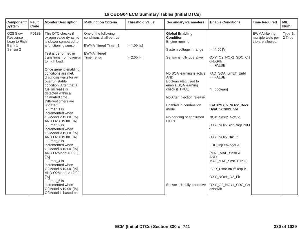
Component/System
FaultCode
Monitor Description Malfunction Criteria Threshold Value Secondary Parameters Enable Conditions Time Required MILIllum.
O2S SlowResponseLean to RichBank 1Sensor 2
P013B This DTC checks ifoxygen value dynamicis slower compared toa functioning sensor.
Test is performed intransitions from overrunto high load.
Once generic enablingconditions are met,diagnosis waits for anoverrun stablecondition. After that afuel increase isdetected within acalibrated time.Different timers areupdated:- Timer_1 is
incremented whenO2Model < [%]19.00AND O2 > [%]19.00- Timer_2 is
incremented whenO2Model < [%]19.00AND O2 < [%]19.00- Timer_3 is
incremented whenO2Model < [%]19.00AND O2Model > 15.00[%]- Timer_4 is
incremented whenO2Model < [%]19.00AND O2Model > 12.00[%]- Timer_5 is
incremented whenO2Model < [%]19.00O2Model is based on
One of the followingconditions shall be true:
EWMA filtered Timer_1
EWMA filteredTimer_error
> [s]1.00
> [-]2.50
Global EnablingConditionEngine running
System voltage in range
Sensor is fully operative
No SQA learning is activeANDBoolean Flag used toenable SQA learningcheck is TRUE
No After Injection release
Enabled in combustionmode
No pending or confirmedDTCs
Sensor 1 is fully operative
> [V]11.00
OXY_O2_NOx2_SDC_CrtdNotRlb== FALSE
FAD_SQA_LrnET_Enbl== FALSE
[boolean]1
KaOXYD_b_NOx2_DecrDynChkCmbEnbl
NOX_Snsr2_NotVld
OXY_NOx2SignRngChkFlt
OXY_NOx2ChkFlt
FHP_InjLeakageFA
(MAF_MAF_SnsrFAAND
)MAF_MAF_SnsrTFTKO
EGR_PstnShtOffReqFA
OXY_NOx1_O2_Flt
OXY_O2_NOx1_SDC_CrtdNotRlb
EWMA filtering:multiple tests pertrip are allowed.
Type B,2 Trips
331
16 OBDG04 ECM Summary Tables (Initial DTCs)
ECM (Initial DTCs) Section 330 of 741 330 of 1039

Component/System
FaultCode
Monitor Description Malfunction Criteria Threshold Value Secondary Parameters Enable Conditions Time Required MILIllum.
Bank 1 Sensor 1 O2measurement.
Test ends when one ofthe following conditionis verified:- O2 < [%]15.00- Timer_5 > [s]30.00- Timer_4 > [s]100.00
After test end, all thefollowing condition shallbe verified to evaluatetest validity:- Timer_4 < [s]100.00- O2Model < [%]12.00- Timer_3 < [s]0.00
If test is valid:Timer_error = (Timer_2- Timer_3) / Timer_3 iscalculated and EWMAis applied on Timer_1and on Time_error.
Additional enablingconditions fortransitioning statemachine from stableoperation state to waitfuel injection state:Operating point reachedand stablei.e. following conditionsare met for a time
a. Engine speed inoperating range
b. Injected fuel quantity
Additional enablingconditions fortransitioning statemachine from wait fuelinjection state to timerevaluation state:Injected fuel quantity
Additional enablingconditions when intimer evaluation state:Injected fuel quantitywithin a time
> [s]1.00
> [rpm]1,250< [rpm]3,000
< [mm^3]1
> [mm^3]1
> [mm^3]20< [s]1.00
332
16 OBDG04 ECM Summary Tables (Initial DTCs)
ECM (Initial DTCs) Section 331 of 741 331 of 1039

Component/System
FaultCode
Monitor Description Malfunction Criteria Threshold Value Secondary Parameters Enable Conditions Time Required MILIllum.
O2 SensorSlowResponse -Rich to LeanBank 1Sensor 1
P014C This DTC checks ifoxygen value dynamicis slower compared toa functioning sensor.
Test is performed intransitions from highload to overrun.
Once generic enablingconditions are met,diagnosis waits forengine operating pointstability (in terms ofengine speed and fuelinjected). When astable operating pointis reached for acalibrated time and anoverrun condition isdetected, the deltabetween the actual O2value (a) and the one infresh air (b = 20.95 %)is calculated.
Then two thresholdsare calculated aspercentage of the initialdelta:O2_Thrsh1 = a + (b - a)* 0.30O2_Thrsh2 = a + (b - a)* 0.70
Two timers areincremented toevaluate sensordynamic while O2moves from O2 initialvalue (a) to O2_Thrsh2
One of the followingconditions shall be true:
EWMA filtered O2 raisingtime from O2 initial value(a) to O2_Thrsh2
EWMA filtered O2 raisingtime from O2_Thrsh1value to O2_Thrsh2
> [s]2.00
> [s]0.80
Global EnablingConditionEngine running
System voltage in range
Sensor is fully operative
(No SQA learning is activeANDBoolean Flag used toenable SQA learningactive status is TRUE)
No After Injection release
No Exhaust Brake activei.e. intake manifoldpressure
Enabled in combustionmode
No pending or confirmedDTCs
> [V]11.00
OXY_NOx1_O2_RawNotRlb== FALSE
FAD_SQA_LrnET_Enbl== FALSE
[boolean]1
< [kPa]299.00
KaOXYD_b_NOx1_IncrDynChkCmbEnbl
NOX_Snsr1_NotVld
OXY_NOx1SignRngMinFlt
OXY_NOx1SignRngMaxFlt
OXY_NOx1ChkOvrrnFlt
OXY_NOx1ChkLoadFlt
FHP_InjLeakageFA
(MAF_MAF_SnsrFAAND
Once per trip
Note: if EWMAFast InitialResponse isactive OREWMA RapidResponse isactive thanmultiple tests pertrip are allowed.
Type B,2 Trips
333
16 OBDG04 ECM Summary Tables (Initial DTCs)
ECM (Initial DTCs) Section 332 of 741 332 of 1039

Component/System
FaultCode
Monitor Description Malfunction Criteria Threshold Value Secondary Parameters Enable Conditions Time Required MILIllum.
and from O2_Thrsh1 toO2_Thrsh2. EWMA isapplied on both timers.
Additional enablingconditions fortransitioning statemachine from stableoperation state to waitoverrun state:Operating point reachedand stablei.e. following conditionsare met for a time
a. Engine speed inoperating range
b. Injected fuel quantity inoperating range
c. Fuel variation
Additional enablingconditions fortransitioning statemachine from waitoverrun state to timerevaluation state:Injected fuel quantity goestoin a time
Additional enablingconditions when intimer evaluation state:EGR position
)MAF_MAF_SnsrTFTKO
EGR_PstnShtOffReqFA
(MAP_SensorFAAND
)MAP_SensorTFTKO
> [s]2.00
> [rpm]1,250< [rpm]3,000
> [mm^3]15< [mm^3]70
< [mm^3]2.00
= 0 [mm^3]< [s]2.00
< [%]100
334
16 OBDG04 ECM Summary Tables (Initial DTCs)
ECM (Initial DTCs) Section 333 of 741 333 of 1039

Component/System
FaultCode
Monitor Description Malfunction Criteria Threshold Value Secondary Parameters Enable Conditions Time Required MILIllum.
O2 SensorSlowResponse -Lean to RichBank 1Sensor 1
P014D This DTC checks ifoxygen value dynamicis slower compared toa functioning sensor.
Test is performed intransitions from overrunto high load.
Once generic enablingconditions are met,diagnosis waits for anoverrun stablecondition. After that afuel increase isdetected within acalibrated time.Different timers areupdated:- Timer_1 is
incremented whenO2Model < [%]19.00AND O2 > [%]19.00- Timer_2 is
incremented whenO2Model < [%]19.00AND O2 < [%]19.00- Timer_3 is
incremented whenO2Model < [%]19.00AND O2Model > 15.00[%]- Timer_4 is
incremented whenO2Model < [%]19.00AND O2Model > 12.00[%]- Timer_5 is
incremented whenO2Model < [%]19.00O2Model is based on
One of the followingconditions shall be true:
EWMA filtered Timer_1
EWMA filteredTimer_error
> [s]1.00
> [-]1.50
Global EnablingConditionEngine running
System voltage in range
Sensor is fully operative
No SQA learning is activeANDBoolean Flag used toenable SQA learningcheck is TRUE
No After Injection release
Enabled in combustionmode
No pending or confirmedDTCs
> [V]11.00
OXY_O2_NOx1_SDC_CrtdNotRlb== FALSE
FAD_SQA_LrnET_Enbl== FALSE
[boolean]1
KaOXYD_b_NOx1_DecrDynChkCmbEnbl
NOX_Snsr1_NotVld
OXY_NOx1SignRngMinFlt
OXY_NOx1SignRngMaxFlt
OXY_NOx1ChkOvrrnFlt
OXY_NOx1ChkLoadFlt
FHP_InjLeakageFA
(MAF_MAF_SnsrFAAND
)MAF_MAF_SnsrTFTKO
EGR_PstnShtOffReqFA
Once per trip
Note: if EWMAFast InitialResponse isactive OREWMA RapidResponse isactive thanmultiple tests pertrip are allowed.
Type B,2 Trips
335
16 OBDG04 ECM Summary Tables (Initial DTCs)
ECM (Initial DTCs) Section 334 of 741 334 of 1039

Component/System
FaultCode
Monitor Description Malfunction Criteria Threshold Value Secondary Parameters Enable Conditions Time Required MILIllum.
injected fuel quantityand air mass.
Test ends when one ofthe following conditionis verified:- O2 < [%]15.00- Timer_5 > [s]10.00- Timer_4 > [s]100.00
After test end, all thefollowing condition shallbe verified to evaluatetest validity:- Timer_4 < [s]100.00- O2Model < [%]12.00- Timer_3 < [s]0.00
If test is valid:Timer_error = (Timer_2- Timer_3) / Timer_3 iscalculated and EWMAis applied on Timer_1and on Time_error.
Additional enablingconditions fortransitioning statemachine from stableoperation state to waitfuel injection state:Operating point reachedand stablei.e. following conditionsare met for a time
a. Engine speed inoperating range
b. Injected fuel quantity
Additional enablingconditions fortransitioning statemachine from wait fuelinjection state to timerevaluation state:Injected fuel quantity
Additional enablingconditions when intimer evaluation state:Injected fuel quantitywithin a time
OXY_O2_NOx1PlausMdlFlt
> [s]1.00
> [rpm]1,250< [rpm]3,000
< [mm^3]1
> [mm^3]1
> [mm^3]20< [s]1.00
336
16 OBDG04 ECM Summary Tables (Initial DTCs)
ECM (Initial DTCs) Section 335 of 741 335 of 1039

Component/System
FaultCode
Monitor Description Malfunction Criteria Threshold Value Secondary Parameters Enable Conditions Time Required MILIllum.
Fuel TrimSystem LeanBank 1
P0171 This DTC monitors ifFSA control system hasreached its maximumauthority and cannotachieve the target.An error shall bedetected when the fueladjustment value(mm3) released by FSAis saturatedat itsminimum value.
Released FSA fuelcorrection value
<KtFADC_V_FSA_FuelMin[mm3]
System voltage in range
FSA correction releaseenabled
(FSA Learning is activeORDFSA Learning is active)for a time
Ambient air pressure
OBD Coolant EnableCriteriaOREngine coolanttemperature
Ambient air temperature
No Low fuel tank levelindication
No pending or confirmedDTCs
> [V]11.00
FAD_FSA_NormRngCrtnValid
(FAD_FSA_EnblLrnOR
)FAD_DFSA_EnblLrn> [s]1.00
> [kPa]67.00
= TRUE
> [°C]45.00
> [°C]-7.00
LowFuelConditionDiagnostic
AmbPresDfltdStatus
(ECT_Sensor_TFTKOAND
)ECT_Sensor_FA
OAT_PtEstFiltFA
Time counter:failures out280
of samples.400
Time task 25[ms]
Type B,2 Trips
337
16 OBDG04 ECM Summary Tables (Initial DTCs)
ECM (Initial DTCs) Section 336 of 741 336 of 1039

Component/System
FaultCode
Monitor Description Malfunction Criteria Threshold Value Secondary Parameters Enable Conditions Time Required MILIllum.
Fuel TrimSystem RichBank 1
P0172 This DTC monitors ifFSA control system hasreached its maximumauthority and cannotachieve the target.An error shall bedetected when the fueladjustment value(mm3) released by FSAis saturatedat itsmaximum value.
Released FSA fuelcorrection value
>KtFADC_V_FSA_FuelMax[mm3]
System voltage in range
FSA correction releaseenabled
(FSA Learning is activeORDFSA Learning is active)for a time
Ambient air pressure
OBD Coolant EnableCriteriaOREngine coolanttemperature
Ambient air temperature
No Low fuel tank levelindication
No pending or confirmedDTCs
> [V]11.00
FAD_FSA_NormRngCrtnValid
(FAD_FSA_EnblLrnOR
)FAD_DFSA_EnblLrn> [s]1.00
> [kPa]67.00
= TRUE
> [°C]45.00
> [°C]-7.00
LowFuelConditionDiagnostic
AmbPresDfltdStatus
(ECT_Sensor_TFTKOAND
)ECT_Sensor_FA
OAT_PtEstFiltFA
Time counter:failures out280
of samples.400
Time task 25[ms]
Type B,2 Trips
338
16 OBDG04 ECM Summary Tables (Initial DTCs)
ECM (Initial DTCs) Section 337 of 741 337 of 1039

Component/System
FaultCode
Monitor Description Malfunction Criteria Threshold Value Secondary Parameters Enable Conditions Time Required MILIllum.
Cylinder 1InjectionTimingPerfomance- OverRetarded
P01CB This diagnosis is ableto detect an excessivenegative drift on fuelinjection quantity andtiming affecting injector1.During Diesel Fuel Cut-off conditions SQAcommand the injectionof a known quantity onone injector (e.g.1,5mm^3) and checks,by means of crank-wheel sensor, theangular accelerationproduced during thecombustion phase. Bycomparing the angularacceleration valueproduced during thecombustion phase withthe angularacceleration that wouldbe produced during thecombustion of anominal fuel quantity(e.g. 1,5mm3), the SQAis able to calculate thedrift, in term ofenergizing time, oninjector 1.Several injections, withdifferent injectionquantities, areperformed in order toextrapolate the resultsand obtain the injectorbehaviour in the smallquantity area.This energizing time isthen used for the
Suspicious confidencelevel of tested injector (Tofail suspicious), functionof Current Energizing timecalculated with SSQA anddelta Energizing timecalculated in the previoustest:KtFADD_Pct_SSQA_InjSuspConfLvl(Delta Enegizing Time,Delta Energizing Timeold)
In case the first test fails:
Delta Energizing timecalculated with VSQA (Tofail Validation)
< [%]50.00
> [us]80.00
SQA Diagnosis enabled
SSQA and VSQA enabledvia calibration
Baro Pressure
Ambient temp
No Low Fuel level tankindication
AND
Boolean Flag used toenable low fuel levelcheck is TRUE
XSQA Learning conditionsenabled
1.00
0.00
>= [kPa]72.00
>= [°C]-7.00
LowFuelConditionDiagnostic
1.00
FAD_XSQA_LrnCondEnbl
Inj_To_PassFail_SSQA Number ofinjections in casesospicious passor (if sospiciousfails)Inj_To_PassFail_SSQA+Inj_To_PassFail_VSQA numberof injections topass or failvalidation
Once per Trip ifsuspicious andvalidations (incase ofsospiciousinjectorsdetected) havebeen alreadycompleted in theprevious drivingcycle, otherwisethe diagnosisstarts from theinterruptedstatus.
Sample Rate: [1Sample everycylinder firingevent].
Type X,No MIL
339
16 OBDG04 ECM Summary Tables (Initial DTCs)
ECM (Initial DTCs) Section 338 of 741 338 of 1039

Component/System
FaultCode
Monitor Description Malfunction Criteria Threshold Value Secondary Parameters Enable Conditions Time Required MILIllum.
diagnostic test that isperformed in twodifferent steps:The first is thesuspicious (SSQA) inwhich all the injectorsare classified assuspicious or notsuspicious. During thisphase severalinjections areperformed on all theinjectors in order tocalculate the drift, interm of energizing time,of each injector. Thedrift found is then usedtogether with the driftfound in the previoustest to enter a calibrate-able map in which aconfidence levelbetween 0 and 100% isgiven to each injector.The confidence levelsdepends on the deltaenergizing timebetween twoconsecutive tests. Aninjector is consideredsuspicious if theconfidence level islower than a calibrate-able threshold.The suspicious phasecan only report testpass for not suspiciousinjectors while theinjectors that fail thesuspicious are testedby means of VSQA(Validation Small
340
16 OBDG04 ECM Summary Tables (Initial DTCs)
ECM (Initial DTCs) Section 339 of 741 339 of 1039

Component/System
FaultCode
Monitor Description Malfunction Criteria Threshold Value Secondary Parameters Enable Conditions Time Required MILIllum.
Quantity Adjustment) inorder to validate or notthe fault.The validation startsfrom the mostsuspicious injector(with lower confidencelevel) found duringSuspicious phase andperforms a calibrate-able number ofinjections, generallyhigher than the numberof injection performedduring suspicious, inorder to find out a moreaccurate drift value forthe tested injector. Ifthe Delta Energizingtime calculated duringthis phase is higherthan a calibrate-ablethreshold a DTC is set.
341
16 OBDG04 ECM Summary Tables (Initial DTCs)
ECM (Initial DTCs) Section 340 of 741 340 of 1039

Component/System
FaultCode
Monitor Description Malfunction Criteria Threshold Value Secondary Parameters Enable Conditions Time Required MILIllum.
Cylinder 1InjectionTimingPerfomance- OverAdvanced
P01CC This diagnosis is ableto detect an excessivepositive drift on fuelinjection quantity andtiming affecting injector1.During Diesel Fuel Cut-off conditions SQAcommand the injectionof a known quantity onone injector (e.g.1,5mm^3) and checks,by means of crank-wheel sensor, theangular accelerationproduced during thecombustion phase. Bycomparing the angularacceleration valueproduced during thecombustion phase withthe angularacceleration that wouldbe produced during thecombustion of anominal fuel quantity(e.g. 1,5mm3), the SQAis able to calculate thedrift, in term ofenergizing time, oninjector 1.Several injections, withdifferent injectionquantities, areperformed in order toextrapolate the resultsand obtain the injectorbehaviour in the smallquantity area.This energizing time isthen used for the
Suspicious confidencelevel of tested injector (Tofail suspicious), functionof Current Energizing timecalculated with SSQA anddelta Energizing timecalculated in the previoustest:KtFADD_Pct_SSQA_InjSuspConfLvl(Delta Enegizing Time,Delta Energizing Timeold)
In case the first test fails:
Delta Energizing timecalculated with VSQA (Tofail Validation)
< [%]50.00
< [us]-80.00
SQA Diagnosis enabled
SSQA and VSQA enabledvia calibration
Baro Pressure
Ambient temp
No Low Fuel level tankindicationANDBoolean Flag used toenable low fuel levelcheck is TRUE
XSQA Learning conditionsenabled
1.00
0.00
>= [kPa]72.00
>= [°C]-7.00
LowFuelConditionDiagnostic
1.00
FAD_XSQA_LrnCondEnbl
Inj_To_PassFail_SSQA Number ofinjections in casesospicious passor (if sospiciousfails)Inj_To_PassFail_SSQA+Inj_To_PassFail_VSQA numberof injections topass or failvalidation
Once per Trip ifsuspicious andvalidations (incase ofsospiciousinjectorsdetected) havebeen alreadycompleted in theprevious drivingcycle, otherwisethe diagnosisstarts from theinterruptedstatus.
Sample Rate: [1Sample everycylinder firingevent].
Type X,No MIL
342
16 OBDG04 ECM Summary Tables (Initial DTCs)
ECM (Initial DTCs) Section 341 of 741 341 of 1039

Component/System
FaultCode
Monitor Description Malfunction Criteria Threshold Value Secondary Parameters Enable Conditions Time Required MILIllum.
diagnostic test that isperformed in twodifferent steps:The first is thesuspicious (SSQA) inwhich all the injectorsare classified assuspicious or notsuspicious. During thisphase severalinjections areperformed on all theinjectors in order tocalculate the drift, interm of energizing time,of each injector. Thedrift found is then usedtogether with the driftfound in the previoustest to enter a calibrate-able map in which aconfidence levelbetween 0 and 100% isgiven to each injector.The confidence levelsdepends on the deltaenergizing timebetween twoconsecutive tests. Aninjector is consideredsuspicious if theconfidence level islower than a calibrate-able threshold.The suspicious phasecan only report testpass for not suspiciousinjectors while theinjectors that fail thesuspicious are testedby means of VSQA(Validation Small
343
16 OBDG04 ECM Summary Tables (Initial DTCs)
ECM (Initial DTCs) Section 342 of 741 342 of 1039

Component/System
FaultCode
Monitor Description Malfunction Criteria Threshold Value Secondary Parameters Enable Conditions Time Required MILIllum.
Quantity Adjustment) inorder to validate or notthe fault.The validation startsfrom the mostsuspicious injector(with lower confidencelevel) found duringSuspicious phase andperforms a calibrate-able number ofinjections, generallyhigher than the numberof injection performedduring suspicious, inorder to find out a moreaccurate drift value forthe tested injector. Ifthe Delta Energizingtime calculated duringthis phase is lower thana calibrate-ablethreshold a DTC is set.
344
16 OBDG04 ECM Summary Tables (Initial DTCs)
ECM (Initial DTCs) Section 343 of 741 343 of 1039

Component/System
FaultCode
Monitor Description Malfunction Criteria Threshold Value Secondary Parameters Enable Conditions Time Required MILIllum.
Cylinder 2InjectionTimingPerfomance- OverRetarded
P01CD This diagnosis is ableto detect an excessivenegative drift on fuelinjection quantity andtiming affecting injector2.During Diesel Fuel Cut-off conditions SQAcommand the injectionof a known quantity onone injector (e.g.1,5mm^3) and checks,by means of crank-wheel sensor, theangular accelerationproduced during thecombustion phase. Bycomparing the angularacceleration valueproduced during thecombustion phase withthe angularacceleration that wouldbe produced during thecombustion of anominal fuel quantity(e.g. 1,5mm3), the SQAis able to calculate thedrift, in term ofenergizing time, oninjector 2.Several injections, withdifferent injectionquantities, areperformed in order toextrapolate the resultsand obtain the injectorbehaviour in the smallquantity area.This energizing time isthen used for the
Suspicious confidencelevel of tested injector (Tofail suspicious), functionof Current Energizing timecalculated with SSQA anddelta Energizing timecalculated in the previoustest:KtFADD_Pct_SSQA_InjSuspConfLvl(Delta Enegizing Time,Delta Energizing Timeold)
In case the first test fails:
Delta Energizing timecalculated with VSQA (Tofail Validation)
< [%]50.00
> [us]80.00
SQA Diagnosis enabled
SSQA and VSQA enabledvia calibration
Baro Pressure
Ambient temp
No Low Fuel level tankindication
AND
Boolean Flag used toenable low fuel levelcheck is TRUE
XSQA Learning conditionsenabled
1.00
0.00
>= [kPa]72.00
>= [°C]-7.00
LowFuelConditionDiagnostic
1.00
FAD_XSQA_LrnCondEnbl
Inj_To_PassFail_SSQA Number ofinjections in casesospicious passor (if sospiciousfails)Inj_To_PassFail_SSQA+Inj_To_PassFail_VSQA numberof injections topass or failvalidation
Once per Trip ifsuspicious andvalidations (incase ofsospiciousinjectorsdetected) havebeen alreadycompleted in theprevious drivingcycle, otherwisethe diagnosisstarts from theinterruptedstatus.
Sample Rate: [1Sample everycylinder firingevent].
Type X,No MIL
345
16 OBDG04 ECM Summary Tables (Initial DTCs)
ECM (Initial DTCs) Section 344 of 741 344 of 1039

Component/System
FaultCode
Monitor Description Malfunction Criteria Threshold Value Secondary Parameters Enable Conditions Time Required MILIllum.
diagnostic test that isperformed in twodifferent steps:The first is thesuspicious (SSQA) inwhich all the injectorsare classified assuspicious or notsuspicious. During thisphase severalinjections areperformed on all theinjectors in order tocalculate the drift, interm of energizing time,of each injector. Thedrift found is then usedtogether with the driftfound in the previoustest to enter a calibrate-able map in which aconfidence levelbetween 0 and 100% isgiven to each injector.The confidence levelsdepends on the deltaenergizing timebetween twoconsecutive tests. Aninjector is consideredsuspicious if theconfidence level islower than a calibrate-able threshold.The suspicious phasecan only report testpass for not suspiciousinjectors while theinjectors that fail thesuspicious are testedby means of VSQA(Validation Small
346
16 OBDG04 ECM Summary Tables (Initial DTCs)
ECM (Initial DTCs) Section 345 of 741 345 of 1039

Component/System
FaultCode
Monitor Description Malfunction Criteria Threshold Value Secondary Parameters Enable Conditions Time Required MILIllum.
Quantity Adjustment) inorder to validate or notthe fault.The validation startsfrom the mostsuspicious injector(with lower confidencelevel) found duringSuspicious phase andperforms a calibrate-able number ofinjections, generallyhigher than the numberof injection performedduring suspicious, inorder to find out a moreaccurate drift value forthe tested injector. Ifthe Delta Energizingtime calculated duringthis phase is higherthan a calibrate-ablethreshold a DTC is set.
347
16 OBDG04 ECM Summary Tables (Initial DTCs)
ECM (Initial DTCs) Section 346 of 741 346 of 1039

Component/System
FaultCode
Monitor Description Malfunction Criteria Threshold Value Secondary Parameters Enable Conditions Time Required MILIllum.
Cylinder 2InjectionTimingPerfomance- OverAdvanced
P01CE This diagnosis is ableto detect an excessivepositive drift on fuelinjection quantity andtiming affecting injector2.During Diesel Fuel Cut-off conditions SQAcommand the injectionof a known quantity onone injector (e.g.1,5mm^3) and checks,by means of crank-wheel sensor, theangular accelerationproduced during thecombustion phase. Bycomparing the angularacceleration valueproduced during thecombustion phase withthe angularacceleration that wouldbe produced during thecombustion of anominal fuel quantity(e.g. 1,5mm3), the SQAis able to calculate thedrift, in term ofenergizing time, oninjector 2.Several injections, withdifferent injectionquantities, areperformed in order toextrapolate the resultsand obtain the injectorbehaviour in the smallquantity area.This energizing time isthen used for the
Suspicious confidencelevel of tested injector (Tofail suspicious), functionof Current Energizing timecalculated with SSQA anddelta Energizing timecalculated in the previoustest:KtFADD_Pct_SSQA_InjSuspConfLvl(Delta Enegizing Time,Delta Energizing Timeold)
In case the first test fails:
Delta Energizing timecalculated with VSQA (Tofail Validation)
< [%]50.00
< [us]-80.00
SQA Diagnosis enabled
SSQA and VSQA enabledvia calibration
Baro Pressure
Ambient temp
No Low Fuel level tankindicationANDBoolean Flag used toenable low fuel levelcheck is TRUE
XSQA Learning conditionsenabled
1.00
0.00
>= [kPa]72.00
>= [°C]-7.00
LowFuelConditionDiagnostic
1.00
FAD_XSQA_LrnCondEnbl
Inj_To_PassFail_SSQA Number ofinjections in casesospicious passor (if sospiciousfails)Inj_To_PassFail_SSQA+Inj_To_PassFail_VSQA numberof injections topass or failvalidation.
Once per Trip ifsuspicious andvalidations (incase ofsospiciousinjectorsdetected) havebeen alreadycompleted in theprevious drivingcycle, otherwisethe diagnosisstarts from theinterruptedstatus.
Sample Rate: [1Sample everycylinder firingevent].
Type X,No MIL
348
16 OBDG04 ECM Summary Tables (Initial DTCs)
ECM (Initial DTCs) Section 347 of 741 347 of 1039

Component/System
FaultCode
Monitor Description Malfunction Criteria Threshold Value Secondary Parameters Enable Conditions Time Required MILIllum.
diagnostic test that isperformed in twodifferent steps:The first is thesuspicious (SSQA) inwhich all the injectorsare classified assuspicious or notsuspicious. During thisphase severalinjections areperformed on all theinjectors in order tocalculate the drift, interm of energizing time,of each injector. Thedrift found is then usedtogether with the driftfound in the previoustest to enter a calibrate-able map in which aconfidence levelbetween 0 and 100% isgiven to each injector.The confidence levelsdepends on the deltaenergizing timebetween twoconsecutive tests. Aninjector is consideredsuspicious if theconfidence level islower than a calibrate-able threshold.The suspicious phasecan only report testpass for not suspiciousinjectors while theinjectors that fail thesuspicious are testedby means of VSQA(Validation Small
349
16 OBDG04 ECM Summary Tables (Initial DTCs)
ECM (Initial DTCs) Section 348 of 741 348 of 1039

Component/System
FaultCode
Monitor Description Malfunction Criteria Threshold Value Secondary Parameters Enable Conditions Time Required MILIllum.
Quantity Adjustment) inorder to validate or notthe fault.The validation startsfrom the mostsuspicious injector(with lower confidencelevel) found duringSuspicious phase andperforms a calibrate-able number ofinjections, generallyhigher than the numberof injection performedduring suspicious, inorder to find out a moreaccurate drift value forthe tested injector. Ifthe Delta Energizingtime calculated duringthis phase is lowerthana calibrate-ablethreshold a DTC is set.
350
16 OBDG04 ECM Summary Tables (Initial DTCs)
ECM (Initial DTCs) Section 349 of 741 349 of 1039

Component/System
FaultCode
Monitor Description Malfunction Criteria Threshold Value Secondary Parameters Enable Conditions Time Required MILIllum.
Cylinder 3InjectionTimingPerfomance- OverRetarded
P01CF This diagnosis is ableto detect an excessivenegative drift on fuelinjection quantity andtiming affecting injector3.During Diesel Fuel Cut-off conditions SQAcommand the injectionof a known quantity onone injector (e.g.1,5mm^3) and checks,by means of crank-wheel sensor, theangular accelerationproduced during thecombustion phase. Bycomparing the angularacceleration valueproduced during thecombustion phase withthe angularacceleration that wouldbe produced during thecombustion of anominal fuel quantity(e.g. 1,5mm3), the SQAis able to calculate thedrift, in term ofenergizing time, oninjector 3.Several injections, withdifferent injectionquantities, areperformed in order toextrapolate the resultsand obtain the injectorbehaviour in the smallquantity area.This energizing time isthen used for the
Suspicious confidencelevel of tested injector (Tofail suspicious), functionof Current Energizing timecalculated with SSQA anddelta Energizing timecalculated in the previoustest:KtFADD_Pct_SSQA_InjSuspConfLvl(Delta Enegizing Time,Delta Energizing Timeold)
In case the first test fails:
Delta Energizing timecalculated by VSQA (Tofail Validation)
< [%]50.00
> [us]80.00
SQA Diagnosis enabled
SSQA and VSQA enabledvia calibration
Baro Pressure
Ambient temp
No Low Fuel level tankindication
AND
Boolean Flag used toenable low fuel levelcheck is TRUE
XSQA Learning conditionsenabled
1.00
0.00
>= [kPa]72.00
>= [°C]-7.00
LowFuelConditionDiagnostic
1.00
FAD_XSQA_LrnCondEnbl
Inj_To_PassFail_SSQA Number ofinjections in casesospicious passor (if sospiciousfails)Inj_To_PassFail_SSQA+Inj_To_PassFail_VSQA numberof injections topass or failvalidation
Once per Trip ifsuspicious andvalidations (incase ofsospiciousinjectorsdetected) havebeen alreadycompleted in theprevious drivingcycle, otherwisethe diagnosisstarts from theinterruptedstatus.
Sample Rate: [1Sample everycylinder firingevent].
Type X,No MIL
351
16 OBDG04 ECM Summary Tables (Initial DTCs)
ECM (Initial DTCs) Section 350 of 741 350 of 1039

Component/System
FaultCode
Monitor Description Malfunction Criteria Threshold Value Secondary Parameters Enable Conditions Time Required MILIllum.
diagnostic test that isperformed in twodifferent steps:The first is thesuspicious (SSQA) inwhich all the injectorsare classified assuspicious or notsuspicious. During thisphase severalinjections areperformed on all theinjectors in order tocalculate the drift, interm of energizing time,of each injector. Thedrift found is then usedtogether with the driftfound in the previoustest to enter a calibrate-able map in which aconfidence levelbetween 0 and 100% isgiven to each injector.The confidence levelsdepends on the deltaenergizing timebetween twoconsecutive tests. Aninjector is consideredsuspicious if theconfidence level islower than a calibrate-able threshold.The suspicious phasecan only report testpass for not suspiciousinjectors while theinjectors that fail thesuspicious are testedby means of VSQA(Validation Small
352
16 OBDG04 ECM Summary Tables (Initial DTCs)
ECM (Initial DTCs) Section 351 of 741 351 of 1039

Component/System
FaultCode
Monitor Description Malfunction Criteria Threshold Value Secondary Parameters Enable Conditions Time Required MILIllum.
Quantity Adjustment) inorder to validate or notthe fault.The validation startsfrom the mostsuspicious injector(with lower confidencelevel) found duringSuspicious phase andperforms a calibrate-able number ofinjections, generallyhigher than the numberof injection performedduring suspicious, inorder to find out a moreaccurate drift value forthe tested injector. Ifthe Delta Energizingtime calculated duringthis phase is higherthan a calibrate-ablethreshold a DTC is set.
353
16 OBDG04 ECM Summary Tables (Initial DTCs)
ECM (Initial DTCs) Section 352 of 741 352 of 1039

Component/System
FaultCode
Monitor Description Malfunction Criteria Threshold Value Secondary Parameters Enable Conditions Time Required MILIllum.
Cylinder 3InjectionTimingPerfomance- OverAdvanced
P01D0 This diagnosis is ableto detect an excessivepositive drift on fuelinjection quantity andtiming affecting injector3.During Diesel Fuel Cut-off conditions SQAcommand the injectionof a known quantity onone injector (e.g.1,5mm^3) and checks,by means of crank-wheel sensor, theangular accelerationproduced during thecombustion phase. Bycomparing the angularacceleration valueproduced during thecombustion phase withthe angularacceleration that wouldbe produced during thecombustion of anominal fuel quantity(e.g. 1,5mm3), the SQAis able to calculate thedrift, in term ofenergizing time, oninjector 3.Several injections, withdifferent injectionquantities, areperformed in order toextrapolate the resultsand obtain the injectorbehaviour in the smallquantity area.This energizing time isthen used for the
Suspicious confidencelevel of tested injector (Tofail suspicious), functionof Current Energizing timecalculated with SSQA anddelta Energizing timecalculated in the previoustest:KtFADD_Pct_SSQA_InjSuspConfLvl(Delta Enegizing Time,Delta Energizing Timeold)
In case the first test fails:
Delta Energizing timecalculated by VSQA (Tofail Validation)
< [%]50.00
< [us]-80.00
SQA Diagnosis enabled
SSQA and VSQA enabled
Baro Pressure
Ambient temp
No Low Fuel level tankindicationANDBoolean Flag used toenable low fuel levelcheck is TRUE
(x)SQA injectionmanagement enabled
1.00
0.00
>= [kPa]72.00
>= [°C]-7.00
LowFuelConditionDiagnostic
1.00
FAD_XSQA_LrnCondEnbl
Inj_To_PassFail_SSQA Number ofinjections in casesospicious passor (if sospiciousfails)Inj_To_PassFail_SSQA+Inj_To_PassFail_VSQA numberof injections topass or failvalidation.
Once per Trip ifsuspicious andvalidations (incase ofsospiciousinjectorsdetected) havebeen alreadycompleted in theprevious drivingcycle, otherwisethe diagnosisstarts from theinterruptedstatus.
Sample Rate: [1Sample everycylinder firingevent].
Type X,No MIL
354
16 OBDG04 ECM Summary Tables (Initial DTCs)
ECM (Initial DTCs) Section 353 of 741 353 of 1039

Component/System
FaultCode
Monitor Description Malfunction Criteria Threshold Value Secondary Parameters Enable Conditions Time Required MILIllum.
diagnostic test that isperformed in twodifferent steps:The first is thesuspicious (SSQA) inwhich all the injectorsare classified assuspicious or notsuspicious. During thisphase severalinjections areperformed on all theinjectors in order tocalculate the drift, interm of energizing time,of each injector. Thedrift found is then usedtogether with the driftfound in the previoustest to enter a calibrate-able map in which aconfidence levelbetween 0 and 100% isgiven to each injector.The confidence levelsdepends on the deltaenergizing timebetween twoconsecutive tests. Aninjector is consideredsuspicious if theconfidence level islower than a calibrate-able threshold.The suspicious phasecan only report testpass for not suspiciousinjectors while theinjectors that fail thesuspicious are testedby means of VSQA(Validation Small
355
16 OBDG04 ECM Summary Tables (Initial DTCs)
ECM (Initial DTCs) Section 354 of 741 354 of 1039

Component/System
FaultCode
Monitor Description Malfunction Criteria Threshold Value Secondary Parameters Enable Conditions Time Required MILIllum.
Quantity Adjustment) inorder to validate or notthe fault.The validation startsfrom the mostsuspicious injector(with lower confidencelevel) found duringSuspicious phase andperforms a calibrate-able number ofinjections, generallyhigher than the numberof injection performedduring suspicious, inorder to find out a moreaccurate drift value forthe tested injector. Ifthe Delta Energizingtime calculated duringthis phase is lowerthana calibrate-ablethreshold a DTC is set.
356
16 OBDG04 ECM Summary Tables (Initial DTCs)
ECM (Initial DTCs) Section 355 of 741 355 of 1039

Component/System
FaultCode
Monitor Description Malfunction Criteria Threshold Value Secondary Parameters Enable Conditions Time Required MILIllum.
Cylinder 4InjectionTimingPerfomance- OverRetarded
P01D1 This diagnosis is ableto detect an excessivenegative drift on fuelinjection quantity andtiming affecting injector4.During Diesel Fuel Cut-off conditions SQAcommand the injectionof a known quantity onone injector (e.g.1,5mm^3) and checks,by means of crank-wheel sensor, theangular accelerationproduced during thecombustion phase. Bycomparing the angularacceleration valueproduced during thecombustion phase withthe angularacceleration that wouldbe produced during thecombustion of anominal fuel quantity(e.g. 1,5mm3), the SQAis able to calculate thedrift, in term ofenergizing time, oninjector 4.Several injections, withdifferent injectionquantities, areperformed in order toextrapolate the resultsand obtain the injectorbehaviour in the smallquantity area.This energizing time isthen used for the
Suspicious confidencelevel of tested injector (Tofail suspicious), functionof Current Energizing timecalculated with SSQA anddelta Energizing timecalculated in the previoustest:KtFADD_Pct_SSQA_InjSuspConfLvl(Delta Enegizing Time,Delta Energizing Timeold)
In case the first test fails:
Delta Energizing timecalculated by VSQA (Tofail Validation)
< [%]50.00
> [us]80.00
SQA Diagnosis enabled
SSQA and VSQA enabled
Baro Pressure
Ambient temp
No Low Fuel level tankindication
AND
Boolean Flag used toenable low fuel levelcheck is TRUE
(x)SQA injectionmanagement enabled
1.00
0.00
>= [kPa]72.00
>= [°C]-7.00
LowFuelConditionDiagnostic
1.00
FAD_XSQA_LrnCondEnbl
Inj_To_PassFail_SSQA Number ofinjections in casesospicious passor (if sospiciousfails)Inj_To_PassFail_SSQA+Inj_To_PassFail_VSQA numberof injections topass or failvalidation
Once per Trip ifsuspicious andvalidations (incase ofsospiciousinjectorsdetected) havebeen alreadycompleted in theprevious drivingcycle, otherwisethe diagnosisstarts from theinterruptedstatus.
Sample Rate: [1Sample everycylinder firingevent].
Type X,No MIL
357
16 OBDG04 ECM Summary Tables (Initial DTCs)
ECM (Initial DTCs) Section 356 of 741 356 of 1039

Component/System
FaultCode
Monitor Description Malfunction Criteria Threshold Value Secondary Parameters Enable Conditions Time Required MILIllum.
diagnostic test that isperformed in twodifferent steps:The first is thesuspicious (SSQA) inwhich all the injectorsare classified assuspicious or notsuspicious. During thisphase severalinjections areperformed on all theinjectors in order tocalculate the drift, interm of energizing time,of each injector. Thedrift found is then usedtogether with the driftfound in the previoustest to enter a calibrate-able map in which aconfidence levelbetween 0 and 100% isgiven to each injector.The confidence levelsdepends on the deltaenergizing timebetween twoconsecutive tests. Aninjector is consideredsuspicious if theconfidence level islower than a calibrate-able threshold.The suspicious phasecan only report testpass for not suspiciousinjectors while theinjectors that fail thesuspicious are testedby means of VSQA(Validation Small
358
16 OBDG04 ECM Summary Tables (Initial DTCs)
ECM (Initial DTCs) Section 357 of 741 357 of 1039

Component/System
FaultCode
Monitor Description Malfunction Criteria Threshold Value Secondary Parameters Enable Conditions Time Required MILIllum.
Quantity Adjustment) inorder to validate or notthe fault.The validation startsfrom the mostsuspicious injector(with lower confidencelevel) found duringSuspicious phase andperforms a calibrate-able number ofinjections, generallyhigher than the numberof injection performedduring suspicious, inorder to find out a moreaccurate drift value forthe tested injector. Ifthe Delta Energizingtime calculated duringthis phase is higherthan a calibrate-ablethreshold a DTC is set.
359
16 OBDG04 ECM Summary Tables (Initial DTCs)
ECM (Initial DTCs) Section 358 of 741 358 of 1039

Component/System
FaultCode
Monitor Description Malfunction Criteria Threshold Value Secondary Parameters Enable Conditions Time Required MILIllum.
Cylinder 4InjectionTimingPerfomance- OverAdvanced
P01D2 This diagnosis is ableto detect an excessivepositive drift on fuelinjection quantity andtiming affecting injector4.During Diesel Fuel Cut-off conditions SQAcommand the injectionof a known quantity onone injector (e.g.1,5mm^3) and checks,by means of crank-wheel sensor, theangular accelerationproduced during thecombustion phase. Bycomparing the angularacceleration valueproduced during thecombustion phase withthe angularacceleration that wouldbe produced during thecombustion of anominal fuel quantity(e.g. 1,5mm3), the SQAis able to calculate thedrift, in term ofenergizing time, oninjector 4.Several injections, withdifferent injectionquantities, areperformed in order toextrapolate the resultsand obtain the injectorbehaviour in the smallquantity area.This energizing time isthen used for the
Suspicious confidencelevel of tested injector (Tofail suspicious), functionof Current Energizing timecalculated with SSQA anddelta Energizing timecalculated in the previoustest:KtFADD_Pct_SSQA_InjSuspConfLvl(Delta Enegizing Time,Delta Energizing Timeold)
In case the first test fails:
Delta Energizing timecalculated by VSQA (Tofail Validation)
< [%]50.00
< [us]-80.00
SQA Diagnosis enabled
SSQA and VSQA enabled
Baro Pressure
Ambient temp
No Low Fuel level tankindicationANDBoolean Flag used toenable low fuel levelcheck is TRUE
(x)SQA injectionmanagement enabled
1.00
0.00
>= [kPa]72.00
>= [°C]-7.00
LowFuelConditionDiagnostic
1.00
FAD_XSQA_LrnCondEnbl
Inj_To_PassFail_SSQA Number ofinjections in casesospicious passor (if sospiciousfails)Inj_To_PassFail_SSQA+Inj_To_PassFail_VSQA numberof injections topass or failvalidation.
Once per Trip ifsuspicious andvalidations (incase ofsospiciousinjectorsdetected) havebeen alreadycompleted in theprevious drivingcycle, otherwisethe diagnosisstarts from theinterruptedstatus.
Sample Rate: [1Sample everycylinder firingevent].
Type X,No MIL
360
16 OBDG04 ECM Summary Tables (Initial DTCs)
ECM (Initial DTCs) Section 359 of 741 359 of 1039

Component/System
FaultCode
Monitor Description Malfunction Criteria Threshold Value Secondary Parameters Enable Conditions Time Required MILIllum.
diagnostic test that isperformed in twodifferent steps:The first is thesuspicious (SSQA) inwhich all the injectorsare classified assuspicious or notsuspicious. During thisphase severalinjections areperformed on all theinjectors in order tocalculate the drift, interm of energizing time,of each injector. Thedrift found is then usedtogether with the driftfound in the previoustest to enter a calibrate-able map in which aconfidence levelbetween 0 and 100% isgiven to each injector.The confidence levelsdepends on the deltaenergizing timebetween twoconsecutive tests. Aninjector is consideredsuspicious if theconfidence level islower than a calibrate-able threshold.The suspicious phasecan only report testpass for not suspiciousinjectors while theinjectors that fail thesuspicious are testedby means of VSQA(Validation Small
361
16 OBDG04 ECM Summary Tables (Initial DTCs)
ECM (Initial DTCs) Section 360 of 741 360 of 1039

Component/System
FaultCode
Monitor Description Malfunction Criteria Threshold Value Secondary Parameters Enable Conditions Time Required MILIllum.
Quantity Adjustment) inorder to validate or notthe fault.The validation startsfrom the mostsuspicious injector(with lower confidencelevel) found duringSuspicious phase andperforms a calibrate-able number ofinjections, generallyhigher than the numberof injection performedduring suspicious, inorder to find out a moreaccurate drift value forthe tested injector. Ifthe Delta Energizingtime calculated duringthis phase is lowerthana calibrate-ablethreshold a DTC is set.
362
16 OBDG04 ECM Summary Tables (Initial DTCs)
ECM (Initial DTCs) Section 361 of 741 361 of 1039

Component/System
FaultCode
Monitor Description Malfunction Criteria Threshold Value Secondary Parameters Enable Conditions Time Required MILIllum.
Injector 1Open Circuit
P0201 This DTC checks theInjector 1 circuit forelectrical integrityduring operation.
Low current through thelow side driver duringoperation indicates opencircuit
Open circuit:circuit attached to theController externalconnections has animpedance >= 200 KOhm
Test enabled bycalibration;
andBattery voltage
andKey ON
andEngine is not cranking
andEngine Running
andFUL_OutEnblCyl_CiEPSR_CylinderA
== [Boolean]1
> [V]11.00
-
-
>= [s]1.00
== 0 [Boolean]
failures out of5samples10
100 ms/sampleContinuous
Type A,1 Trips
363
16 OBDG04 ECM Summary Tables (Initial DTCs)
ECM (Initial DTCs) Section 362 of 741 362 of 1039

Component/System
FaultCode
Monitor Description Malfunction Criteria Threshold Value Secondary Parameters Enable Conditions Time Required MILIllum.
Injector 2Open Circuit
P0202 This DTC checks theInjector 2 circuit forelectrical integrityduring operation.
Low current through thelow side driver duringoperation indicates opencircuit
Open circuit:circuit attached to theController externalconnections has animpedance >= 200 KOhm
Test enabled bycalibration;
andBattery voltage
andKey ON
andEngine is not cranking
andEngine Running
andFUL_OutEnblCyl_CiEPSR_CylinderD
== [Boolean]1
> [V]11.00
-
-
>= [s]1.00
== 0 [Boolean]
failures out of5samples10
100 ms/sampleContinuous
Type A,1 Trips
364
16 OBDG04 ECM Summary Tables (Initial DTCs)
ECM (Initial DTCs) Section 363 of 741 363 of 1039

Component/System
FaultCode
Monitor Description Malfunction Criteria Threshold Value Secondary Parameters Enable Conditions Time Required MILIllum.
Injector 3Open Circuit
P0203 This DTC checks theInjector 3 circuit forelectrical integrityduring operation.
Low current through thelow side driver duringoperation indicates opencircuit
Open circuit:circuit attached to theController externalconnections has animpedance >= 200 KOhm
Test enabled bycalibration;
andBattery voltage
andKey ON
andEngine is not cranking
andEngine Running
andFUL_OutEnblCyl_CiEPSR_CylinderB
== [Boolean]1
> [V]11.00
-
-
>= [s]1.00
== 0 [Boolean]
failures out of5samples10
100 ms/sampleContinuous
Type A,1 Trips
365
16 OBDG04 ECM Summary Tables (Initial DTCs)
ECM (Initial DTCs) Section 364 of 741 364 of 1039

Component/System
FaultCode
Monitor Description Malfunction Criteria Threshold Value Secondary Parameters Enable Conditions Time Required MILIllum.
Injector 4Open Circuit
P0204 This DTC checks theInjector 4 circuit forelectrical integrityduring operation.
Low current through thelow side driver duringoperation indicates opencircuit
Open circuit:circuit attached to theController externalconnections has animpedance >= 200 KOhm
Test enabled bycalibration;
andBattery voltage
andKey ON
andEngine is not cranking
andEngine Running
andFUL_OutEnblCyl_CiEPSR_CylinderC
== [Boolean]1
> [V]11.00
-
-
>= [s]1.00
== 0 [Boolean]
failures out of5samples10
100 ms/sampleContinuous
Type A,1 Trips
366
16 OBDG04 ECM Summary Tables (Initial DTCs)
ECM (Initial DTCs) Section 365 of 741 365 of 1039

Component/System
FaultCode
Monitor Description Malfunction Criteria Threshold Value Secondary Parameters Enable Conditions Time Required MILIllum.
Cylinder 1InjectionTiming
P020A This DTC detects anInjector fault or ECUfault that causes pull Inperiod of the currentpulse out of range oninjector 1The pull in period is thetime for the injectioncurrent to rise to thecurrent level ( 17.50[A]) at the beginning ofthe pulse
Measurement of the PullIn period of the currentpulse of the injector 1provided by HWIO
< [us]0.00
OR
> [us]130.00
Test enabled bycalibration;
andBattery voltage
andKey ON
andNo active DTC's:
andAt least one injectionpulse is requested by theapplication software(FUL_FuelInjectedCyl_CiEPSR_CylinderA
== [Boolean]1
> [V]11.00
-
FUL_InjCktTFTKOFUL_CntrlrStTFTKOFUL_BoostVoltTFTKO
-
== TRUE);
failures out10of samples20
1 sample everyengine cycle
Continuous
Type A,1 Trips
367
16 OBDG04 ECM Summary Tables (Initial DTCs)
ECM (Initial DTCs) Section 366 of 741 366 of 1039

Component/System
FaultCode
Monitor Description Malfunction Criteria Threshold Value Secondary Parameters Enable Conditions Time Required MILIllum.
Cylinder 2InjectionTiming
P020B This DTC detects anInjector fault or ECUfault that causes pull Inperiod of the currentpulse out of range oninjector 2The pull in period is thetime for the injectioncurrent to rise to thecurrent level ( 17.50[A]) at the beginning ofthe pulse
Measurement of the PullIn period of the currentpulse of the injector 2provided by HWIO
< [us]0.00
OR
> [us]130.00
Test enabled bycalibration;
andBattery voltage
andKey ON
andNo active DTC's:
andAt least one injectionpulse is requested by theapplication software(FUL_FuelInjectedCyl_CiEPSR_CylinderD
== [Boolean]1
> [V]11.00
-
FUL_InjCktTFTKOFUL_CntrlrStTFTKOFUL_BoostVoltTFTKO
-
== TRUE);
failures out10of samples20
1 sample everyengine cycle
Continuous
Type A,1 Trips
368
16 OBDG04 ECM Summary Tables (Initial DTCs)
ECM (Initial DTCs) Section 367 of 741 367 of 1039

Component/System
FaultCode
Monitor Description Malfunction Criteria Threshold Value Secondary Parameters Enable Conditions Time Required MILIllum.
Cylinder 3InjectionTiming
P020C This DTC detects anInjector fault or ECUfault that causes pull Inperiod of the currentpulse out of range oninjector 3The pull in period is thetime for the injectioncurrent to rise to thecurrent level ( 17.50[A]) at the beginning ofthe pulse
Measurement of the PullIn period of the currentpulse of the injector 3provided by HWIO
< [us]0.00
OR
> [us]130.00
Test enabled bycalibration;
andBattery voltage
andKey ON
andNo active DTC's:
andAt least one injectionpulse is requested by theapplication software;(FUL_FuelInjectedCyl_CiEPSR_CylinderB
== [Boolean]1
> [V]11.00
-
FUL_InjCktTFTKOFUL_CntrlrStTFTKOFUL_BoostVoltTFTKO
-
== TRUE);
failures out10of samples20
1 sample everyengine cycle
Continuous
Type A,1 Trips
369
16 OBDG04 ECM Summary Tables (Initial DTCs)
ECM (Initial DTCs) Section 368 of 741 368 of 1039

Component/System
FaultCode
Monitor Description Malfunction Criteria Threshold Value Secondary Parameters Enable Conditions Time Required MILIllum.
Cylinder 4InjectionTiming
P020D This DTC detects anInjector fault or ECUfault that causes pull Inperiod of the currentpulse out of range oninjector 4The pull in period is thetime for the injectioncurrent to rise to thecurrent level ( 17.50[A]) at the beginning ofthe pulse
Measurement of the PullIn period of the currentpulse of the injector 4provided by HWIO
< [us]0.00
OR
> [us]130.00
Test enabled bycalibration;
andBattery voltage
andKey ON
andNo active DTC's:
andAt least one injectionpulse is requested by theapplication software;(FUL_FuelInjectedCyl_CiEPSR_CylinderC
== [Boolean]1
> [V]11.00
-
FUL_InjCktTFTKOFUL_CntrlrStTFTKOFUL_BoostVoltTFTKO
-
== TRUE);
failures out10of samples20
1 sample everyengine cycle
Continuous
Type A,1 Trips
370
16 OBDG04 ECM Summary Tables (Initial DTCs)
ECM (Initial DTCs) Section 369 of 741 369 of 1039

Component/System
FaultCode
Monitor Description Malfunction Criteria Threshold Value Secondary Parameters Enable Conditions Time Required MILIllum.
Injector 1ControlCircuit LowVoltage
P0261 This DTC detects ashort circuit to groundof the low side drivercircuit of Injector 1.
Voltage low across lowside drive during off stateindicates short-to-ground
Short to ground:impedence betweenLS pin and controllerground <= 0.5 [Ohm]
Test enabled bycalibration;
andBattery voltage
andKey ON
andEngine is not cranking
andEngine Running
andFUL_OutEnblCyl_CiEPSR_CylinderA
== [Boolean]1
> [V]11.00
-
-
>= [s]1.00
== 0 [Boolean]
failures out of5samples10
100 ms/sampleContinuous
Type A,1 Trips
371
16 OBDG04 ECM Summary Tables (Initial DTCs)
ECM (Initial DTCs) Section 370 of 741 370 of 1039

Component/System
FaultCode
Monitor Description Malfunction Criteria Threshold Value Secondary Parameters Enable Conditions Time Required MILIllum.
Injector 1ControlCircuit HighVoltage
P0262 This DTC detects ashort circuit to powersupply of the low sidedriver circuit of Injector1
Voltage high across lowside driver during Onstate indicates short topower
Short to power:impedence betweenLS pin and controllerpower <= 0.5 [Ohm]
Test enabled bycalibration;
andBattery voltage
andKey ON
andEngine is not cranking
andEngine Running
andFUL_OutEnblCyl_CiEPSR_CylinderA
== [Boolean]1
> [V]11.00
-
-
>= [s]1.00
== 0 [Boolean]
failures out of5samples10
100 ms/sampleContinuous
Type A,1 Trips
372
16 OBDG04 ECM Summary Tables (Initial DTCs)
ECM (Initial DTCs) Section 371 of 741 371 of 1039

Component/System
FaultCode
Monitor Description Malfunction Criteria Threshold Value Secondary Parameters Enable Conditions Time Required MILIllum.
CylinderBalance 1MaximumAuthorityReached
P0263 The Cylinder Balancing(CB) strategy is able toget a cylinder bycylinder external torqueequalization to improveengine smooth running(less engine speedroughness, moredriving comfort)..The Cylinder Balancinguses as input of theclosed loop theunbalancing signal andprovide, as output, thefuel volume correctionto apply on eachcylinder. The target ofthe closed loop is to getzero unbalancing on allcylinders. Theunbalancing signalcointains the torqueformed during thecombustion phase ofeach cylinder.This diagnosis is ableto detect if CylinderBalancing fuel volumecorrectionapplied oncylinder 1 reach thesaturation (positive ornegative) withoutachieve the target (zerounbalancing).When CB correction forcylinder 1 reach thesaturation (positive ornegative) the CBcontrol system sets aBoolean flag to true inorder to inform the Max
Cylinder Balancing FuelVolume Correction oncylinder 1 saturated(positive or negative).
FAD_CB_Cyl_A_HiSaturated==TRUEORFAD_CB_Cyl_A_LoSaturated==TRUE
Test enabled bycalibration
No faults detected oninjectors
Fuel Injector DisableDevice Control not active
CB enabled in closed loop
EOL injector codes written
No errors related toredundant calculation ofEOL injector codes
No Low fuel tank levelindication
Fuel request higher than acalibrateable threshold
Engine coolanttemperature higher than acalibrateable threshold
No faults on Enginecoolant temperaturesensor.
1.00
FUL_GenericInjSysFlt
FUL_InjectorDisable
FAD_CB_CntrlType==CeFADC_e_CB_CL_Enbl
FAD_EIA_DID_Written
FAD_EIA_RedntFlt
LowFuelConditionDiagnostic
>= [mm3/stroke]15.00
>= [°C]-20.00
(ECT_Sensor_TFTKOAND
)ECT_Sensor_FA
Fails125.00Samples over
samples.175.00
1 sample everycylinder firingevent.
Type B,2 Trips
373
16 OBDG04 ECM Summary Tables (Initial DTCs)
ECM (Initial DTCs) Section 372 of 741 372 of 1039

Component/System
FaultCode
Monitor Description Malfunction Criteria Threshold Value Secondary Parameters Enable Conditions Time Required MILIllum.
Authority diagnosis thatthe Cylinder 1 issaturated.If this signal remainstrue for a debouncingtime a DTC is stored.
374
16 OBDG04 ECM Summary Tables (Initial DTCs)
ECM (Initial DTCs) Section 373 of 741 373 of 1039

Component/System
FaultCode
Monitor Description Malfunction Criteria Threshold Value Secondary Parameters Enable Conditions Time Required MILIllum.
Injector 2ControlCircuit LowVoltage
P0264 This DTC detects ashort circuit to groundof the low side drivercircuit of Injector 2.
Voltage low across lowside drive during off stateindicates short-to-ground
Short to ground:impedence betweenLS pin and controllerground <= 0.5 [Ohm]
Test enabled bycalibration;
andBattery voltage
andKey ON
andEngine is not cranking
andEngine Running
andFUL_OutEnblCyl_CiEPSR_CylinderD
== [Boolean]1
> [V]11.00
-
-
>= [s]1.00
== 0 [Boolean]
failures out of5samples10
100 ms/sampleContinuous
Type A,1 Trips
375
16 OBDG04 ECM Summary Tables (Initial DTCs)
ECM (Initial DTCs) Section 374 of 741 374 of 1039
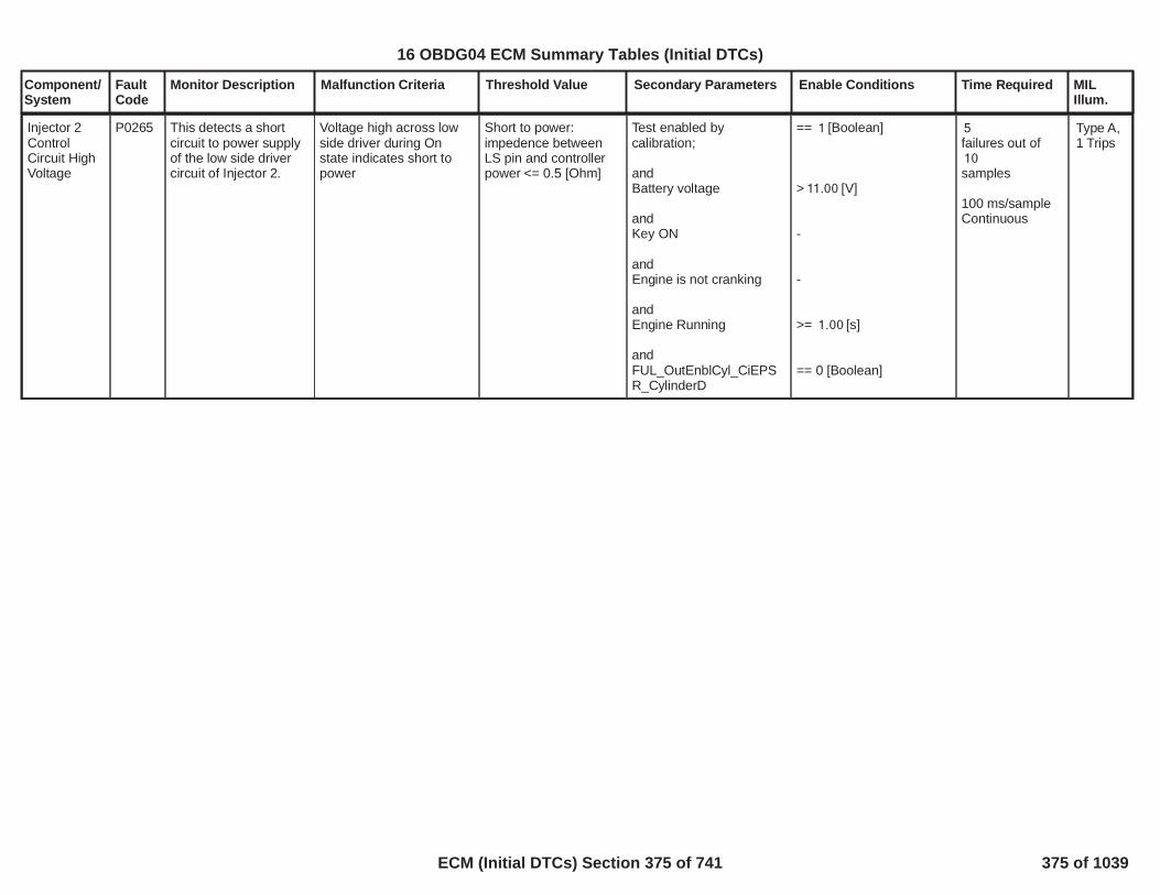
Component/System
FaultCode
Monitor Description Malfunction Criteria Threshold Value Secondary Parameters Enable Conditions Time Required MILIllum.
Injector 2ControlCircuit HighVoltage
P0265 This detects a shortcircuit to power supplyof the low side drivercircuit of Injector 2.
Voltage high across lowside driver during Onstate indicates short topower
Short to power:impedence betweenLS pin and controllerpower <= 0.5 [Ohm]
Test enabled bycalibration;
andBattery voltage
andKey ON
andEngine is not cranking
andEngine Running
andFUL_OutEnblCyl_CiEPSR_CylinderD
== [Boolean]1
> [V]11.00
-
-
>= [s]1.00
== 0 [Boolean]
5failures out of10samples
100 ms/sampleContinuous
Type A,1 Trips
376
16 OBDG04 ECM Summary Tables (Initial DTCs)
ECM (Initial DTCs) Section 375 of 741 375 of 1039

Component/System
FaultCode
Monitor Description Malfunction Criteria Threshold Value Secondary Parameters Enable Conditions Time Required MILIllum.
CylinderBalance 2MaximumAuthorityReached
P0266 The Cylinder Balancing(CB) strategy is able toget a cylinder bycylinder external torqueequalization to improveengine smooth running(less engine speedroughness, moredriving comfort)..The Cylinder Balancinguses as input of theclosed loop theunbalancing signal andprovide, as output, thefuel volume correctionto apply on eachcylinder. The target ofthe closed loop is to getzero unbalancing on allcylinders. Theunbalancing signalcointains the torqueformed during thecombustion phase ofeach cylinder.This diagnosis is ableto detect if CylinderBalancing fuel volumecorrectionapplied oncylinder 2 reach thesaturation (positive ornegative) withoutachieve the target (zerounbalancing).When CB correction forcylinder 2 reach thesaturation (positive ornegative) the CBcontrol system sets aBoolean flag to true inorder to inform the Max
Cylinder Balancing FuelVolume Correction oncylinder 2 saturated(positive or negative).
FAD_CB_Cyl_D_HiSaturated==TRUE
ORFAD_CB_Cyl_D_LoSaturated==TRUE
Test enabled bycalibration
No faults detected oninjectors
Fuel Injector DisableDevice Control not active
CB enabled in closed loop
EOL injector codes written
No errors related toredundant calculation ofEOL injector codes
No Low fuel tank levelindication
Fuel request higher than acalibrateable threshold
Engine coolanttemperature higher than acalibrateable threshold
No faults on Enginecoolant temperaturesensor.
1.00
FUL_GenericInjSysFlt
FUL_InjectorDisable
FAD_CB_CntrlType==CeFADC_e_CB_CL_Enbl
FAD_EIA_DID_Written
FAD_EIA_RedntFlt
LowFuelConditionDiagnostic
>= [mm3/stroke]15.00
>= [°C]-20.00
(ECT_Sensor_TFTKOAND
)ECT_Sensor_FA
Fail125.00Samples over
samples.175.00
1 sample everycylinder firingevent.
Type B,2 Trips
377
16 OBDG04 ECM Summary Tables (Initial DTCs)
ECM (Initial DTCs) Section 376 of 741 376 of 1039

Component/System
FaultCode
Monitor Description Malfunction Criteria Threshold Value Secondary Parameters Enable Conditions Time Required MILIllum.
Authority diagnosis thatthe Cylinder 2 issaturated.If this signal remainstrue for a debouncingtime a DTC is stored.
378
16 OBDG04 ECM Summary Tables (Initial DTCs)
ECM (Initial DTCs) Section 377 of 741 377 of 1039

Component/System
FaultCode
Monitor Description Malfunction Criteria Threshold Value Secondary Parameters Enable Conditions Time Required MILIllum.
Injector 3ControlCircuit LowVoltage
P0267 This DTC detects ashort circuit to groundof the low side drivercircuit of Injector 3.
Voltage low across lowside drive during off stateindicates short-to-ground
Short to ground:impedence betweenLS pin and controllerground <= 0.5 [Ohm]
Test enabled bycalibration;
andBattery voltage
andKey ON
andEngine is not cranking
andEngine Running
andFUL_OutEnblCyl_CiEPSR_CylinderB
== [Boolean]1
> [V]11.00
-
-
>= [s]1.00
== 0 [Boolean]
failures out of5samples10
100 ms/sampleContinuous
Type A,1 Trips
379
16 OBDG04 ECM Summary Tables (Initial DTCs)
ECM (Initial DTCs) Section 378 of 741 378 of 1039

Component/System
FaultCode
Monitor Description Malfunction Criteria Threshold Value Secondary Parameters Enable Conditions Time Required MILIllum.
Injector 3ControlCircuit HighVoltage
P0268 This DTC detects ashort circuit to powersupply of the low sidedriver circuit of Injector3.
Voltage high across lowside driver during Onstate indicates short topower
Short to power:impedence betweenLS pin and controllerpower <= 0.5 [Ohm]
Test enabled bycalibration;
andBattery voltage
andKey ON
andEngine is not cranking
andEngine Running
andFUL_OutEnblCyl_CiEPSR_CylinderB
== [Boolean]1
> [V]11.00
-
-
>= [s]1.00
== 0 [Boolean]
5failures out of10samples
100 ms/sampleContinuous
Type A,1 Trips
380
16 OBDG04 ECM Summary Tables (Initial DTCs)
ECM (Initial DTCs) Section 379 of 741 379 of 1039

Component/System
FaultCode
Monitor Description Malfunction Criteria Threshold Value Secondary Parameters Enable Conditions Time Required MILIllum.
CylinderBalance 3MaximumAuthorityReached
P0269 The Cylinder Balancing(CB) strategy is able toget a cylinder bycylinder external torqueequalization to improveengine smooth running(less engine speedroughness, moredriving comfort)..The Cylinder Balancinguses as input of theclosed loop theunbalancing signal andprovide, as output, thefuel volume correctionto apply on eachcylinder. The target ofthe closed loop is to getzero unbalancing on allcylinders. Theunbalancing signalcointains the torqueformed during thecombustion phase ofeach cylinder.This diagnosis is ableto detect if CylinderBalancing fuel volumecorrectionapplied oncylinder 3 reach thesaturation (positive ornegative) withoutachieve the target (zerounbalancing).When CB correction forcylinder 3 reach thesaturation (positive ornegative) the CBcontrol system sets aBoolean flag to true inorder to inform the Max
Cylinder Balancing FuelVolume Correction oncylinder 3 saturated(positive or negative).
FAD_CB_Cyl_B_HiSaturated==TRUE
ORFAD_CB_Cyl_B_LoSaturated==TRUE
Test enabled bycalibration
No faults detected oninjectors
Fuel Injector DisableDevice Control not active
CB enabled in closed loop
EOL injector codes written
No errors related toredundant calculation ofEOL injector codes
No Low fuel tank levelindication
Fuel request higher than acalibrateable threshold
Engine coolanttemperature higher than acalibrateable threshold
No faults on Enginecoolant temperaturesensor.
1.00
FUL_GenericInjSysFlt
FUL_InjectorDisable
FAD_CB_CntrlType==CeFADC_e_CB_CL_Enbl
FAD_EIA_DID_Written
FAD_EIA_RedntFlt
LowFuelConditionDiagnostic
>= [mm3/stroke]15.00
>= [°C]-20.00
(ECT_Sensor_TFTKOAND
)ECT_Sensor_FA
Fail125.00Samples over
samples.175.00
1 sample everycylinder firingevent.
Type B,2 Trips
381
16 OBDG04 ECM Summary Tables (Initial DTCs)
ECM (Initial DTCs) Section 380 of 741 380 of 1039

Component/System
FaultCode
Monitor Description Malfunction Criteria Threshold Value Secondary Parameters Enable Conditions Time Required MILIllum.
Authority diagnosis thatthe Cylinder 3 issaturated.If this signal remainstrue for a debouncingtime a DTC is stored.
382
16 OBDG04 ECM Summary Tables (Initial DTCs)
ECM (Initial DTCs) Section 381 of 741 381 of 1039

Component/System
FaultCode
Monitor Description Malfunction Criteria Threshold Value Secondary Parameters Enable Conditions Time Required MILIllum.
Charge AirCoolerEfficiencyBelowThreshold
P026A This monitor checks ifthe charge air cooler isefficently working
The efficiency value iscalculated using thecharger air coolerupstream anddownstream temperatureand the Engine coolanttemperature.
The average value of thiscalculation is comparedwith a calibratablethreshold.
< [%]50.00
Test enabled bycalibration
The vehicle speed shallbe greater than acalibratable value
Air mass flow within acalibratable window
The engine coolanttemperature shall begreater than a calibratablethresholdOROBD Coolant EnableCriteria
The throttle value shall begreater than a calibratalbevalue
The pressure compressorratio shall be greater thana calibratable value
The temperaturedifference from upstreamcharge air cooler and theambient temperature shallbe greater than acalibratable value
The environmental
==TRUE1.00
> [kph]40.00
> [mg/s]20.00< [mg/s]2,000.00
> [°C]70.00
==TRUE
> [%]90.00
> [ratio]1.30
> [°C]40.00
> [kPa]69.60
Test executedafter a counter of
samples800.00
Function task:100 ms
Type B,2 Trips
383
16 OBDG04 ECM Summary Tables (Initial DTCs)
ECM (Initial DTCs) Section 382 of 741 382 of 1039

Component/System
FaultCode
Monitor Description Malfunction Criteria Threshold Value Secondary Parameters Enable Conditions Time Required MILIllum.
pressure shall be greaterthan a calibratable value
The environmentaltemperature shall begreater than a calibratablevalue
No fault on vehicle speed
No fault on engineecoolant temperature
No fault on throttleposition
No fault on ambientpressure
No fault on ambienttemperature
No fault on charge aircooler upstream anddownstream temperaturesensors
No fault on MAF sensors
All the enabling conditionsshall be fulfilled for a
> [°C]-7.00
VehicleSpeedSensor_FA==FALSE
ECT_Sensor_FA==FALSE
TPS_PstnSnsrFA==FALSE
AAP_AmbientAirPresDfltd==FALSE
OAT_PtEstFiltFA==FALSE
==FALSECIT_CAC_UpFACIT_CAC_DwnFA==FALSE
MAF_MAF_SnsrFA==FALSE
>= [s]0.50
384
16 OBDG04 ECM Summary Tables (Initial DTCs)
ECM (Initial DTCs) Section 383 of 741 383 of 1039

Component/System
FaultCode
Monitor Description Malfunction Criteria Threshold Value Secondary Parameters Enable Conditions Time Required MILIllum.
calibrate-able time
385
16 OBDG04 ECM Summary Tables (Initial DTCs)
ECM (Initial DTCs) Section 384 of 741 384 of 1039

Component/System
FaultCode
Monitor Description Malfunction Criteria Threshold Value Secondary Parameters Enable Conditions Time Required MILIllum.
FuelInjectionQuantityLower ThanExpected
P026C An error shall bedetected when the fueladjustment value(mm3) released by FSAis below a calibratedthreshold.
Released FSA fuelcorrection value
<KtFADD_V_FSA_ECM_LoThrsh[mm^3]
System voltage in range
FSA correction releaseenabled
(FSA Learning is activeORDFSA Learning is active)for a time
Ambient air pressure
OBD Coolant EnableCriteriaOREngine coolanttemperature
Ambient air temperature
Gear engaged
Engine speedfor a time
Injected fuel quantityfor a time
Vehicle speedfor a time
No Low fuel tank levelindication
No pending or confirmedDTCs
> [V]11.00
FAD_FSA_NormRngCrtnValid
(FAD_FSA_EnblLrnOR
)FAD_DFSA_EnblLrn> [s]8.00
> [kPa]67.00
= TRUE
> [°C]45.00
> [°C]-7.00
different from Neutral orParking
< [rpm]1,200> *0.025 [s]255
< [mm^3]65.00> *0.025 [s]255
< [kph]3.0> *0.025 [s]255
LowFuelConditionDiagnostic
AmbPresDfltdStatus
(ECT_Sensor_TFTKOAND
)ECT_Sensor_FA
Time counter:failures out280
of samples.560
Time task 25[ms]
Type B,2 Trips
386
16 OBDG04 ECM Summary Tables (Initial DTCs)
ECM (Initial DTCs) Section 385 of 741 385 of 1039

Component/System
FaultCode
Monitor Description Malfunction Criteria Threshold Value Secondary Parameters Enable Conditions Time Required MILIllum.
OAT_PtEstFiltFA
FAD_FSA_LrnShtOffReq
OXY_eqr_TurbDwn_FSA_NotVld
Transmission EstimatedGear Validity
387
16 OBDG04 ECM Summary Tables (Initial DTCs)
ECM (Initial DTCs) Section 386 of 741 386 of 1039

Component/System
FaultCode
Monitor Description Malfunction Criteria Threshold Value Secondary Parameters Enable Conditions Time Required MILIllum.
FuelInjectionQuantityHigher ThanExpected
P026D An error shall bedetected when the fueladjustment value(mm^3) released byFSA is above acalibrated threshold.
Released FSA fuelcorrection value
>KtFADD_V_FSA_ECM_HiThrsh[mm^3]
System voltage in range
FSA correction releaseenabled
(FSA Learning is activeORDFSA Learning is active)for a time
Ambient air pressure
OBD Coolant EnableCriteriaOREngine coolanttemperature
Ambient air temperature
Gear engaged
Engine speedfor a time
Injected fuel quantityfor a time
Vehicle speedfor a time
No Low fuel tank levelindication
No pending or confirmedDTCs
> [V]11.00
FAD_FSA_NormRngCrtnValid
(FAD_FSA_EnblLrnOR
)FAD_DFSA_EnblLrn> [s]8.00
> [kPa]67.00
= TRUE
> [°C]45.00
> [°C]-7.00
different from Neutral orParking
< [rpm]1,200> *0.025 [s]255
< [mm^3]65.00> *0.025 [s]255
< [kph3.0> *0.025 [s]255
LowFuelConditionDiagnostic
AmbPresDfltdStatus
(ECT_Sensor_TFTKOAND
)ECT_Sensor_FA
Time counter:failures out280
of samples.560
Time task 25[ms]
Type B,2 Trips
388
16 OBDG04 ECM Summary Tables (Initial DTCs)
ECM (Initial DTCs) Section 387 of 741 387 of 1039

Component/System
FaultCode
Monitor Description Malfunction Criteria Threshold Value Secondary Parameters Enable Conditions Time Required MILIllum.
OAT_PtEstFiltFA
FAD_FSA_LrnShtOffReq
OXY_eqr_TurbDwn_FSA_NotVld
Transmission EstimatedGear Validity
389
16 OBDG04 ECM Summary Tables (Initial DTCs)
ECM (Initial DTCs) Section 388 of 741 388 of 1039

Component/System
FaultCode
Monitor Description Malfunction Criteria Threshold Value Secondary Parameters Enable Conditions Time Required MILIllum.
Injector 4ControlCircuit LowVoltage
P0270 This DTC detects ashort circuit to groundof the low side drivercircuit of Injector 4.
Voltage low across lowside drive during off stateindicates short-to-ground
Short to ground:impedence betweenLS pin and controllerground <= 0.5 [Ohm]
Test enabled bycalibration;
andBattery voltage
andKey ON
andEngine is not cranking
andEngine Running
andFUL_OutEnblCyl_CiEPSR_CylinderC
== [Boolean]1
> [V]11.00
-
-
>= [s]1.00
== 0 [Boolean]
failures out of5samples10
100 ms/sampleContinuous
Type A,1 Trips
390
16 OBDG04 ECM Summary Tables (Initial DTCs)
ECM (Initial DTCs) Section 389 of 741 389 of 1039

Component/System
FaultCode
Monitor Description Malfunction Criteria Threshold Value Secondary Parameters Enable Conditions Time Required MILIllum.
Injector 4ControlCircuit HighVoltage
P0271 This DTC detects ashort circuit to powersupply of the low sidedriver circuit of Injector4.
Voltage high across lowside driver during Onstate indicates short topower
Short to power:impedence betweenLS pin and controllerpower <= 0.5 [Ohm]
Test enabled bycalibration;
andBattery voltage
andKey ON
andEngine is not cranking
andEngine Running
andFUL_OutEnblCyl_CiEPSR_CylinderC
== [Boolean]1
> [V]11.00
-
-
>= [s]1.00
== 0 [Boolean]
5failures out of10samples
100 ms/sampleContinuous
Type A,1 Trips
391
16 OBDG04 ECM Summary Tables (Initial DTCs)
ECM (Initial DTCs) Section 390 of 741 390 of 1039

Component/System
FaultCode
Monitor Description Malfunction Criteria Threshold Value Secondary Parameters Enable Conditions Time Required MILIllum.
CylinderBalance 4MaximumAuthorityReached
P0272 The Cylinder Balancing(CB) strategy is able toget a cylinder bycylinder external torqueequalization to improveengine smooth running(less engine speedroughness, moredriving comfort)..The Cylinder Balancinguses as input of theclosed loop theunbalancing signal andprovide, as output, thefuel volume correctionto apply on eachcylinder. The target ofthe closed loop is to getzero unbalancing on allcylinders. Theunbalancing signalcointains the torqueformed during thecombustion phase ofeach cylinder.This diagnosis is ableto detect if CylinderBalancing fuel volumecorrectionapplied oncylinder 4 reach thesaturation (positive ornegative) withoutachieve the target (zerounbalancing).When CB correction forcylinder 4 reach thesaturation (positive ornegative) the CBcontrol system sets aBoolean flag to true inorder to inform the Max
Cylinder Balancing FuelVolume Correction oncylinder 4 saturated(positive or negative).
FAD_CB_Cyl_C_HiSaturated==TRUEORFAD_CB_Cyl_C_LoSaturated==TRUE
Test enabled bycalibration
No faults detected oninjectors
Fuel Injector DisableDevice Control not active
CB enabled in closed loop
EOL injector codes written
No errors related toredundant calculation ofEOL injector codes
No Low fuel tank levelindication
Fuel request higher than acalibrateable threshold
Engine coolanttemperature higher than acalibrateable threshold
No faults on Enginecoolant temperaturesensor.
1.00
FUL_GenericInjSysFlt
FUL_InjectorDisable
FAD_CB_CntrlType==CeFADC_e_CB_CL_Enbl
FAD_EIA_DID_Written
FAD_EIA_RedntFlt
LowFuelConditionDiagnostic
>= [mm3/stroke]15.00
>= [°C]-20.00
(ECT_Sensor_TFTKOAND
)ECT_Sensor_FA
Fail125.00Samples over
samples.175.00
1 sample everycylinder firingevent.
Type B,2 Trips
392
16 OBDG04 ECM Summary Tables (Initial DTCs)
ECM (Initial DTCs) Section 391 of 741 391 of 1039

Component/System
FaultCode
Monitor Description Malfunction Criteria Threshold Value Secondary Parameters Enable Conditions Time Required MILIllum.
Authority diagnosis thatthe Cylinder 4 issaturated.If this signal remainstrue for a debouncingtime a DTC is stored.
393
16 OBDG04 ECM Summary Tables (Initial DTCs)
ECM (Initial DTCs) Section 392 of 741 392 of 1039

Component/System
FaultCode
Monitor Description Malfunction Criteria Threshold Value Secondary Parameters Enable Conditions Time Required MILIllum.
Each time a new value isentered in SQA map thediagnosis checks if:
- DeltaET learnt by (x)SQA on cylinder 1.
The result of this test isthen stored in a booleanNV array cointaing thestatus of Minimumauthority test(TRUE=Saturated,FALSE= Not saturated)for all the rail pressurelevels defined for SQA.The DTC for minimumauthority reached is set if,at least one element ofthe array is equal toTRUE and is unset whenall the elements of thearray are equal to FALSE.
<KaFADC_t_SQA_MinAdptDeltET[us]
SQA Diagnosis enabled
(x)SQA injectionmanagement enabled
1.00
FAD_SQA_InjMgntEnbld
Time required toperform alearning with (x)SQA.
1 Sample everycylinder firingevent.
Cylinder 1Fuel InjectorOffsetLearning AtMin Limit
P02CC This diagnosis (MinAuthority monitoring)performs a check onthe absolute EnergizingTime learnt by SQA(Small QuantityAdjustment).During Diesel Fuel Cut-off conditions SQAcommand the injectionof a known quantity onone injector (e.g.1,5mm^3) and checks,by means of crank-wheel sensor, thetorque produced duringthe combustion phase.Two different learningstrategies are used:Target SQA (TSQA):This strategy is aclosed loop betweenfuel quantity injectedand torque producedduring combustionphase. The fuelquantity injected isincreased/decreaseduntil the angularacceleration target isreached. The DeltaEnergizing Timeneeded to achieve thetarget is then stored inSQA Map.Extrapolated SQA(ESQA): With thisstrategy severalinjections with differentinjection quantities areperformed and, for
Type B,2 Trips
394
16 OBDG04 ECM Summary Tables (Initial DTCs)
ECM (Initial DTCs) Section 393 of 741 393 of 1039

Component/System
FaultCode
Monitor Description Malfunction Criteria Threshold Value Secondary Parameters Enable Conditions Time Required MILIllum.
each quantity, a deltaET is calculated usingthe difference betweenthe torque producedduring the combustionphase and the torquethat would be producedduring the combustionof a nominal fuelquantity. The resultsare then extrapolated inorder to find thebehaviour in all smallquantity area.Each time a new valueis entered in SQA map,regardless thestrategies used toperform the learning(TSQA, ESQA, …), thediagnosis checks if theDeltaET learned bySQA is lower than acalibrateable threshold.The result of this test isthen stored in aboolean NV arraycontaining the status ofMinimum authority test(TRUE=Saturated,FALSE= Not saturated)for all the rail pressurelevels defined for SQA.The DTC for minimumauthority reached is setif, at least one elementof the array is equal toTRUE and is unsetwhen all the elementsof the array are equalto FALSE (no saturatedvalues stored in SQA
395
16 OBDG04 ECM Summary Tables (Initial DTCs)
ECM (Initial DTCs) Section 394 of 741 394 of 1039

Component/System
FaultCode
Monitor Description Malfunction Criteria Threshold Value Secondary Parameters Enable Conditions Time Required MILIllum.
map).
396
16 OBDG04 ECM Summary Tables (Initial DTCs)
ECM (Initial DTCs) Section 395 of 741 395 of 1039

Component/System
FaultCode
Monitor Description Malfunction Criteria Threshold Value Secondary Parameters Enable Conditions Time Required MILIllum.
Each time a new value isentered in SQA map thediagnosis checks if:
- DeltaET learnt by (x)SQA on cylinder 1.
The result of this test isthen stored in a booleanNV array cointaing thestatus of Maximumauthority test(TRUE=Saturated,FALSE= Not saturated)for all the rail pressurelevels defined for SQA.The DTC for maximumauthority reached is set if,at least one element ofthe array is equal toTRUE and is unset whenall the elements of thearray are equal to FALSE.
>KaFADC_t_SQA_MaxAdptDeltET[us]
SQA Diagnosis enabled
(x)SQA injectionmanagement enabled
1.00
FAD_SQA_InjMgntEnbld
Time required toperform alearning with (x)SQA.
[Sample Rate: 1Sample everycylinder firingevent].
Cylinder 1Fuel InjectorOffsetLearning AtMax Limit
P02CD This diagnosis (MaxAuthority monitoring)performs a check onthe absolute EnergizingTime learnt by SQA(Small QuantityAdjustment).During Diesel Fuel Cut-off conditions SQAcommand the injectionof a known quantity onone injector (e.g.1,5mm^3) and checks,by means of crank-wheel sensor, thetorque produced duringthe combustion phase.Two different learningstrategies are used:Target SQA (TSQA):This strategy is aclosed loop betweenfuel quantity injectedand torque producedduring combustionphase. The fuelquantity injected isincreased/decreaseduntil the angularacceleration target isreached. The DeltaEnergizing Timeneeded to achieve thetarget is then stored inSQA Map.Extrapolated SQA(ESQA): With thisstrategy severalinjections with differentinjection quantities areperformed and, for
Type B,2 Trips
397
16 OBDG04 ECM Summary Tables (Initial DTCs)
ECM (Initial DTCs) Section 396 of 741 396 of 1039

Component/System
FaultCode
Monitor Description Malfunction Criteria Threshold Value Secondary Parameters Enable Conditions Time Required MILIllum.
each quantity, a deltaET is calculated usingthe difference betweenthe torque producedduring the combustionphase and the torquethat would be producedduring the combustionof a nominal fuelquantity. The resultsare then extrapolated inorder to find thebehaviour in all smallquantity area.Each time a new valueis entered in SQA map,regardless thestrategies used toperform the learning(TSQA, ESQA, …), thediagnosis checks if theDeltaET learned bySQA is higher than acalibrateable threshold.The result of this test isthen stored in aboolean NV arraycontaining the status ofMaximum authority test(TRUE=Saturated,FALSE= Not saturated)for all the rail pressurelevels defined for SQA.The DTC for maximumauthority reached is setif, at least one elementof the array is equal toTRUE and is unsetwhen all the elementsof the array are equalto FALSE (no saturatedvalues stored in SQA
398
16 OBDG04 ECM Summary Tables (Initial DTCs)
ECM (Initial DTCs) Section 397 of 741 397 of 1039

Component/System
FaultCode
Monitor Description Malfunction Criteria Threshold Value Secondary Parameters Enable Conditions Time Required MILIllum.
map).
399
16 OBDG04 ECM Summary Tables (Initial DTCs)
ECM (Initial DTCs) Section 398 of 741 398 of 1039

Component/System
FaultCode
Monitor Description Malfunction Criteria Threshold Value Secondary Parameters Enable Conditions Time Required MILIllum.
Cylinder 2Fuel InjectorOffsetLearning AtMin Limit
P02CE This diagnosis (MinAuthority monitoring)performs a check onthe absolute EnergizingTime learnt by SQA(Small QuantityAdjustment).During Diesel Fuel Cut-off conditions SQAcommand the injectionof a known quantity onone injector (e.g.1,5mm^3) and checks,by means of crank-wheel sensor, thetorque produced duringthe combustion phase.Two different learningstrategies are used:Target SQA (TSQA):This strategy is aclosed loop betweenfuel quantity injectedand torque producedduring combustionphase. The fuelquantity injected isincreased/decreaseduntil the angularacceleration target isreached. The DeltaEnergizing Timeneeded to achieve thetarget is then stored inSQA Map.Extrapolated SQA(ESQA): With thisstrategy severalinjections with differentinjection quantities areperformed and, for
Each time a new value isentered in SQA map thediagnosis checks if:
- DeltaET learnt by (x)SQA on cylinder 2.
The result of this test isthen stored in a booleanNV array cointaing thestatus of Minimumauthority test(TRUE=Saturated,FALSE= Not saturated)for all the rail pressurelevels defined for SQA.The DTC for minimumauthority reached is set if,at least one element ofthe array is equal toTRUE and is unset whenall the elements of thearray are equal to FALSE.
<KaFADC_t_SQA_MinAdptDeltET[us]
SQA Diagnosis enabled
(x)SQA injectionmanagement enabled
1.00
FAD_SQA_InjMgntEnbld
Time required toperform alearning with (x)SQA.
[Sample Rate: 1Sample everycylinder firingevent].
Type B,2 Trips
400
16 OBDG04 ECM Summary Tables (Initial DTCs)
ECM (Initial DTCs) Section 399 of 741 399 of 1039

Component/System
FaultCode
Monitor Description Malfunction Criteria Threshold Value Secondary Parameters Enable Conditions Time Required MILIllum.
each quantity, a deltaET is calculated usingthe difference betweenthe torque producedduring the combustionphase and the torquethat would be producedduring the combustionof a nominal fuelquantity. The resultsare then extrapolated inorder to find thebehaviour in all smallquantity area.Each time a new valueis entered in SQA map,regardless thestrategies used toperform the learning(TSQA, ESQA, …), thediagnosis checks if theDeltaET learned bySQA is lower than acalibrateable threshold.The result of this test isthen stored in aboolean NV arraycontaining the status ofMinimum authority test(TRUE=Saturated,FALSE= Not saturated)for all the rail pressurelevels defined for SQA.The DTC for minimumauthority reached is setif, at least one elementof the array is equal toTRUE and is unsetwhen all the elementsof the array are equalto FALSE (no saturatedvalues stored in SQA
401
16 OBDG04 ECM Summary Tables (Initial DTCs)
ECM (Initial DTCs) Section 400 of 741 400 of 1039

Component/System
FaultCode
Monitor Description Malfunction Criteria Threshold Value Secondary Parameters Enable Conditions Time Required MILIllum.
map).
402
16 OBDG04 ECM Summary Tables (Initial DTCs)
ECM (Initial DTCs) Section 401 of 741 401 of 1039

Component/System
FaultCode
Monitor Description Malfunction Criteria Threshold Value Secondary Parameters Enable Conditions Time Required MILIllum.
Cylinder 2Fuel InjectorOffsetLearning AtMax Limit
P02CF This diagnosis (MaxAuthority monitoring)performs a check onthe absolute EnergizingTime learnt by SQA(Small QuantityAdjustment).During Diesel Fuel Cut-off conditions SQAcommand the injectionof a known quantity onone injector (e.g.1,5mm^3) and checks,by means of crank-wheel sensor, thetorque produced duringthe combustion phase.Two different learningstrategies are used:Target SQA (TSQA):This strategy is aclosed loop betweenfuel quantity injectedand torque producedduring combustionphase. The fuelquantity injected isincreased/decreaseduntil the angularacceleration target isreached. The DeltaEnergizing Timeneeded to achieve thetarget is then stored inSQA Map.Extrapolated SQA(ESQA): With thisstrategy severalinjections with differentinjection quantities areperformed and, for
Each time a new value isentered in SQA map thediagnosis checks if:
- DeltaET learnt by (x)SQA on cylinder 2.
The result of this test isthen stored in a booleanNV array cointaing thestatus of Maximumauthority test(TRUE=Saturated,FALSE= Not saturated)for all the rail pressurelevels defined for SQA.The DTC for maximumauthority reached is set if,at least one element ofthe array is equal toTRUE and is unset whenall the elements of thearray are equal to FALSE.
>KaFADC_t_SQA_MaxAdptDeltET[us]
SQA Diagnosis enabled
(x)SQA injectionmanagement enabled
1.00
FAD_SQA_InjMgntEnbld
Time required toperform alearning with (x)SQA.
[Sample Rate: 1Sample everycylinder firingevent].
Type B,2 Trips
403
16 OBDG04 ECM Summary Tables (Initial DTCs)
ECM (Initial DTCs) Section 402 of 741 402 of 1039

Component/System
FaultCode
Monitor Description Malfunction Criteria Threshold Value Secondary Parameters Enable Conditions Time Required MILIllum.
each quantity, a deltaET is calculated usingthe difference betweenthe torque producedduring the combustionphase and the torquethat would be producedduring the combustionof a nominal fuelquantity. The resultsare then extrapolated inorder to find thebehaviour in all smallquantity area.Each time a new valueis entered in SQA map,regardless thestrategies used toperform the learning(TSQA, ESQA, …), thediagnosis checks if theDeltaET learned bySQA is higher than acalibrateable threshold.The result of this test isthen stored in aboolean NV arraycontaining the status ofMaximum authority test(TRUE=Saturated,FALSE= Not saturated)for all the rail pressurelevels defined for SQA.The DTC for maximumauthority reached is setif, at least one elementof the array is equal toTRUE and is unsetwhen all the elementsof the array are equalto FALSE (no saturatedvalues stored in SQA
404
16 OBDG04 ECM Summary Tables (Initial DTCs)
ECM (Initial DTCs) Section 403 of 741 403 of 1039

Component/System
FaultCode
Monitor Description Malfunction Criteria Threshold Value Secondary Parameters Enable Conditions Time Required MILIllum.
map).
405
16 OBDG04 ECM Summary Tables (Initial DTCs)
ECM (Initial DTCs) Section 404 of 741 404 of 1039

Component/System
FaultCode
Monitor Description Malfunction Criteria Threshold Value Secondary Parameters Enable Conditions Time Required MILIllum.
Cylinder 3Fuel InjectorOffsetLearning AtMin Limit
P02D0 This diagnosis (MinAuthority monitoring)performs a check onthe absolute EnergizingTime learnt by SQA(Small QuantityAdjustment).During Diesel Fuel Cut-off conditions SQAcommand the injectionof a known quantity onone injector (e.g.1,5mm^3) and checks,by means of crank-wheel sensor, thetorque produced duringthe combustion phase.Two different learningstrategies are used:Target SQA (TSQA):This strategy is aclosed loop betweenfuel quantity injectedand torque producedduring combustionphase. The fuelquantity injected isincreased/decreaseduntil the angularacceleration target isreached. The DeltaEnergizing Timeneeded to achieve thetarget is then stored inSQA Map.Extrapolated SQA(ESQA): With thisstrategy severalinjections with differentinjection quantities areperformed and, for
Each time a new value isentered in SQA map thediagnosis checks if:
- DeltaET learnt by (x)SQA on cylinder 3.
The result of this test isthen stored in a booleanNV array cointaing thestatus of Minimumauthority test(TRUE=Saturated,FALSE= Not saturated)for all the rail pressurelevels defined for SQA.The DTC for minimumauthority reached is set if,at least one element ofthe array is equal toTRUE and is unset whenall the elements of thearray are equal to FALSE.
<KaFADC_t_SQA_MinAdptDeltET[us]
SQA Diagnosis enabled
(x)SQA injectionmanagement enabled
1.00
FAD_SQA_InjMgntEnbld
Time required toperform alearning with (x)SQA.
[Sample Rate: 1Sample everycylinder firingevent].
Type B,2 Trips
406
16 OBDG04 ECM Summary Tables (Initial DTCs)
ECM (Initial DTCs) Section 405 of 741 405 of 1039

Component/System
FaultCode
Monitor Description Malfunction Criteria Threshold Value Secondary Parameters Enable Conditions Time Required MILIllum.
each quantity, a deltaET is calculated usingthe difference betweenthe torque producedduring the combustionphase and the torquethat would be producedduring the combustionof a nominal fuelquantity. The resultsare then extrapolated inorder to find thebehaviour in all smallquantity area.Each time a new valueis entered in SQA map,regardless thestrategies used toperform the learning(TSQA, ESQA, …), thediagnosis checks if theDeltaET learned bySQA is lower than acalibrateable threshold.The result of this test isthen stored in aboolean NV arraycontaining the status ofMinimum authority test(TRUE=Saturated,FALSE= Not saturated)for all the rail pressurelevels defined for SQA.The DTC for minimumauthority reached is setif, at least one elementof the array is equal toTRUE and is unsetwhen all the elementsof the array are equalto FALSE (no saturatedvalues stored in SQA
407
16 OBDG04 ECM Summary Tables (Initial DTCs)
ECM (Initial DTCs) Section 406 of 741 406 of 1039
Component/System
FaultCode
Monitor Description Malfunction Criteria Threshold Value Secondary Parameters Enable Conditions Time Required MILIllum.
map).
408
16 OBDG04 ECM Summary Tables (Initial DTCs)
ECM (Initial DTCs) Section 407 of 741 407 of 1039

Component/System
FaultCode
Monitor Description Malfunction Criteria Threshold Value Secondary Parameters Enable Conditions Time Required MILIllum.
Cylinder 3Fuel InjectorOffsetLearning AtMax Limit
P02D1 This diagnosis (MaxAuthority monitoring)performs a check onthe absolute EnergizingTime learnt by SQA(Small QuantityAdjustment).During Diesel Fuel Cut-off conditions SQAcommand the injectionof a known quantity onone injector (e.g.1,5mm^3) and checks,by means of crank-wheel sensor, thetorque produced duringthe combustion phase.Two different learningstrategies are used:Target SQA (TSQA):This strategy is aclosed loop betweenfuel quantity injectedand torque producedduring combustionphase. The fuelquantity injected isincreased/decreaseduntil the angularacceleration target isreached. The DeltaEnergizing Timeneeded to achieve thetarget is then stored inSQA Map.Extrapolated SQA(ESQA): With thisstrategy severalinjections with differentinjection quantities areperformed and, for
Each time a new value isentered in SQA map thediagnosis checks if:
- DeltaET learnt by (x)SQA on cylinder 3
The result of this test isthen stored in a booleanNV array cointaing thestatus of Maximumauthority test(TRUE=Saturated,FALSE= Not saturated)for all the rail pressurelevels defined for SQA.The DTC for maximumauthority reached is set if,at least one element ofthe array is equal toTRUE and is unset whenall the elements of thearray are equal to FALSE.
>KaFADC_t_SQA_MaxAdptDeltET[us]
SQA Diagnosis enabled
(x)SQA injectionmanagement enabled
1.00
FAD_SQA_InjMgntEnbld
Time required toperform alearning with (x)SQA.
[Sample Rate: 1Sample everycylinder firingevent].
Type B,2 Trips
409
16 OBDG04 ECM Summary Tables (Initial DTCs)
ECM (Initial DTCs) Section 408 of 741 408 of 1039

Component/System
FaultCode
Monitor Description Malfunction Criteria Threshold Value Secondary Parameters Enable Conditions Time Required MILIllum.
each quantity, a deltaET is calculated usingthe difference betweenthe torque producedduring the combustionphase and the torquethat would be producedduring the combustionof a nominal fuelquantity. The resultsare then extrapolated inorder to find thebehaviour in all smallquantity area.Each time a new valueis entered in SQA map,regardless thestrategies used toperform the learning(TSQA, ESQA, …), thediagnosis checks if theDeltaET learned bySQA is higher than acalibrateable threshold.The result of this test isthen stored in aboolean NV arraycontaining the status ofMaximum authority test(TRUE=Saturated,FALSE= Not saturated)for all the rail pressurelevels defined for SQA.The DTC for maximumauthority reached is setif, at least one elementof the array is equal toTRUE and is unsetwhen all the elementsof the array are equalto FALSE (no saturatedvalues stored in SQA
410
16 OBDG04 ECM Summary Tables (Initial DTCs)
ECM (Initial DTCs) Section 409 of 741 409 of 1039

Component/System
FaultCode
Monitor Description Malfunction Criteria Threshold Value Secondary Parameters Enable Conditions Time Required MILIllum.
map).
411
16 OBDG04 ECM Summary Tables (Initial DTCs)
ECM (Initial DTCs) Section 410 of 741 410 of 1039

Component/System
FaultCode
Monitor Description Malfunction Criteria Threshold Value Secondary Parameters Enable Conditions Time Required MILIllum.
Cylinder 4Fuel InjectorOffsetLearning AtMin Limit
P02D2 This diagnosis (MinAuthority monitoring)performs a check onthe absolute EnergizingTime learnt by SQA(Small QuantityAdjustment).During Diesel Fuel Cut-off conditions SQAcommand the injectionof a known quantity onone injector (e.g.1,5mm^3) and checks,by means of crank-wheel sensor, thetorque produced duringthe combustion phase.Two different learningstrategies are used:Target SQA (TSQA):This strategy is aclosed loop betweenfuel quantity injectedand torque producedduring combustionphase. The fuelquantity injected isincreased/decreaseduntil the angularacceleration target isreached. The DeltaEnergizing Timeneeded to achieve thetarget is then stored inSQA Map.Extrapolated SQA(ESQA): With thisstrategy severalinjections with differentinjection quantities areperformed and, for
Each time a new value isentered in SQA map thediagnosis checks if:
- DeltaET learnt by (x)SQA on cylinder 4.
The result of this test isthen stored in a booleanNV array cointaing thestatus of Minimumauthority test(TRUE=Saturated,FALSE= Not saturated)for all the rail pressurelevels defined for SQA.The DTC for minimumauthority reached is set if,at least one element ofthe array is equal toTRUE and is unset whenall the elements of thearray are equal to FALSE.
<KaFADC_t_SQA_MinAdptDeltET[us]
SQA Diagnosis enabled
(x)SQA injectionmanagement enabled
1.00
FAD_SQA_InjMgntEnbld
Time required toperform alearning with (x)SQA.
[Sample Rate: 1Sample everycylinder firingevent].
Type B,2 Trips
412
16 OBDG04 ECM Summary Tables (Initial DTCs)
ECM (Initial DTCs) Section 411 of 741 411 of 1039

Component/System
FaultCode
Monitor Description Malfunction Criteria Threshold Value Secondary Parameters Enable Conditions Time Required MILIllum.
each quantity, a deltaET is calculated usingthe difference betweenthe torque producedduring the combustionphase and the torquethat would be producedduring the combustionof a nominal fuelquantity. The resultsare then extrapolated inorder to find thebehaviour in all smallquantity area.Each time a new valueis entered in SQA map,regardless thestrategies used toperform the learning(TSQA, ESQA, …), thediagnosis checks if theDeltaET learned bySQA is lower than acalibrateable threshold.The result of this test isthen stored in aboolean NV arraycontaining the status ofMinimum authority test(TRUE=Saturated,FALSE= Not saturated)for all the rail pressurelevels defined for SQA.The DTC for minimumauthority reached is setif, at least one elementof the array is equal toTRUE and is unsetwhen all the elementsof the array are equalto FALSE (no saturatedvalues stored in SQA
413
16 OBDG04 ECM Summary Tables (Initial DTCs)
ECM (Initial DTCs) Section 412 of 741 412 of 1039

Component/System
FaultCode
Monitor Description Malfunction Criteria Threshold Value Secondary Parameters Enable Conditions Time Required MILIllum.
map).
414
16 OBDG04 ECM Summary Tables (Initial DTCs)
ECM (Initial DTCs) Section 413 of 741 413 of 1039

Component/System
FaultCode
Monitor Description Malfunction Criteria Threshold Value Secondary Parameters Enable Conditions Time Required MILIllum.
Cylinder 4Fuel InjectorOffsetLearning AtMax Limit
P02D3 This diagnosis (MaxAuthority monitoring)performs a check onthe absolute EnergizingTime learnt by SQA(Small QuantityAdjustment).During Diesel Fuel Cut-off conditions SQAcommand the injectionof a known quantity onone injector (e.g.1,5mm^3) and checks,by means of crank-wheel sensor, thetorque produced duringthe combustion phase.Two different learningstrategies are used:Target SQA (TSQA):This strategy is aclosed loop betweenfuel quantity injectedand torque producedduring combustionphase. The fuelquantity injected isincreased/decreaseduntil the angularacceleration target isreached. The DeltaEnergizing Timeneeded to achieve thetarget is then stored inSQA Map.Extrapolated SQA(ESQA): With thisstrategy severalinjections with differentinjection quantities areperformed and, for
Each time a new value isentered in SQA map thediagnosis checks if:
- DeltaET learnt by (x)SQA on cylinder 4
The result of this test isthen stored in a booleanNV array cointaing thestatus of Maximumauthority test(TRUE=Saturated,FALSE= Not saturated)for all the rail pressurelevels defined for SQA.The DTC for maximumauthority reached is set if,at least one element ofthe array is equal toTRUE and is unset whenall the elements of thearray are equal to FALSE.
>KaFADC_t_SQA_MaxAdptDeltET[us]
SQA Diagnosis enabled
(x)SQA injectionmanagement enabled
1.00
FAD_SQA_InjMgntEnbld
Time required toperform alearning with (x)SQA.
[Sample Rate: 1Sample everycylinder firingevent].
Type B,2 Trips
415
16 OBDG04 ECM Summary Tables (Initial DTCs)
ECM (Initial DTCs) Section 414 of 741 414 of 1039

Component/System
FaultCode
Monitor Description Malfunction Criteria Threshold Value Secondary Parameters Enable Conditions Time Required MILIllum.
each quantity, a deltaET is calculated usingthe difference betweenthe torque producedduring the combustionphase and the torquethat would be producedduring the combustionof a nominal fuelquantity. The resultsare then extrapolated inorder to find thebehaviour in all smallquantity area.Each time a new valueis entered in SQA map,regardless thestrategies used toperform the learning(TSQA, ESQA, …), thediagnosis checks if theDeltaET learned bySQA is higher than acalibrateable threshold.The result of this test isthen stored in aboolean NV arraycontaining the status ofMaximum authority test(TRUE=Saturated,FALSE= Not saturated)for all the rail pressurelevels defined for SQA.The DTC for maximumauthority reached is setif, at least one elementof the array is equal toTRUE and is unsetwhen all the elementsof the array are equalto FALSE (no saturatedvalues stored in SQA
416
16 OBDG04 ECM Summary Tables (Initial DTCs)
ECM (Initial DTCs) Section 415 of 741 415 of 1039

Component/System
FaultCode
Monitor Description Malfunction Criteria Threshold Value Secondary Parameters Enable Conditions Time Required MILIllum.
map).
417
16 OBDG04 ECM Summary Tables (Initial DTCs)
ECM (Initial DTCs) Section 416 of 741 416 of 1039

Component/System
FaultCode
Monitor Description Malfunction Criteria Threshold Value Secondary Parameters Enable Conditions Time Required MILIllum.
Diesel IntakeAir FlowControlCircuit/Open
P02E0 This monitor checks ifthe Throttle commandsare in open circuit
Error interface providedby HWIO
Error interfaceprovided by HWIO ==TRUE
Test enabled bycalibration
System out of thecranking phase
PT relay supply voltage inrange
Error interface providedby HWIO !=INDETERMINATE
Valve moved to a positiondifferent from wide open
==TRUE1.00
> [V]11.00
96.00fail counts out of
sample120.00counts
Function task:12.5 ms
Type B,2 Trips
418
16 OBDG04 ECM Summary Tables (Initial DTCs)
ECM (Initial DTCs) Section 417 of 741 417 of 1039

Component/System
FaultCode
Monitor Description Malfunction Criteria Threshold Value Secondary Parameters Enable Conditions Time Required MILIllum.
Diesel IntakeAir FlowControlCircuit Low
P02E2 This monitor checks ifthe Throttle commandsare shorted to ground
Error interface providedby HWIO
Error interfaceprovided by HWIO ==TRUE
Test enabled bycalibration
System out of thecranking phase
PT relay supply voltage inrange
Error interface providedby HWIO !=INDETERMINATE
==TRUE1.00
> [V]11.00
96.00fail counts out of
sample120.00counts
Function task:12.5 ms
Type B,2 Trips
419
16 OBDG04 ECM Summary Tables (Initial DTCs)
ECM (Initial DTCs) Section 418 of 741 418 of 1039

Component/System
FaultCode
Monitor Description Malfunction Criteria Threshold Value Secondary Parameters Enable Conditions Time Required MILIllum.
Diesel IntakeAir FlowControlCircuit High
P02E3 This monitor checks ifthe Throttle commandsare shorted to powersupply
Error interface providedby HWIO
Error interfaceprovided by HWIO ==TRUE
Test enabled bycalibration
System out of thecranking phase
PT relay supply voltage inrange
Error interface providedby HWIO !=INDETERMINATE
==TRUE1.00
> [V]11.00
96.00fail counts out of
sample120.00counts
Function task:12.5 ms
Type B,2 Trips
420
16 OBDG04 ECM Summary Tables (Initial DTCs)
ECM (Initial DTCs) Section 419 of 741 419 of 1039

Component/System
FaultCode
Monitor Description Malfunction Criteria Threshold Value Secondary Parameters Enable Conditions Time Required MILIllum.
Diesel IntakeAir FlowControlStuck Open
P02E4 This monitor checks ifthe Throttle valve gotmechanically stuck in aposition more openthan what is requiredby the control
position tracking error(setpoint position -measured position) <negative threshold
AND
valve duty cycle <negative threshold
< [%]-8.00
AND
< [%]-80.00
Test enabled bycalibration
System out of thecranking phase
Position control in closedloop (no faults present onThrottle position sensor,Throttle valve, Throttleposition deviation)
== TRUE1.00
==TPS_PstnShtOffReqTRUE
640.00fail counts out of800.00sample counts
Function task:6.25 ms
after
96.00fail counts out of120.00sample counts
Function task:12.5 ms
Type A,1 Trips
421
16 OBDG04 ECM Summary Tables (Initial DTCs)
ECM (Initial DTCs) Section 420 of 741 420 of 1039

Component/System
FaultCode
Monitor Description Malfunction Criteria Threshold Value Secondary Parameters Enable Conditions Time Required MILIllum.
Diesel IntakeAir FlowControlStuckClosed
P02E5 This monitor checks ifthe Throttle valve gotmechanically stuck in aposition more closedthan what is requiredby the control
position tracking error(setpoint position -measured position) >positive threshold
AND
valve duty cycle > positivethreshold
> [%]8.00
AND
> [%]80.00
Test enabled bycalibration
System out of thecranking phase
Position control in closedloop (no faults present onThrottle position sensor,Throttle valve, Throttleposition deviation)
== TRUE1.00
==TPS_PstnShtOffReqFALSE
640.00fail counts out of800.00sample counts
Function task:6.25 ms
Type A,1 Trips
422
16 OBDG04 ECM Summary Tables (Initial DTCs)
ECM (Initial DTCs) Section 421 of 741 421 of 1039

Component/System
FaultCode
Monitor Description Malfunction Criteria Threshold Value Secondary Parameters Enable Conditions Time Required MILIllum.
analog position rawvoltage < low threshold
< %5V1.00 Test enabled bycalibration
System out of thecranking phase
PT relay supply voltage inrange
==TRUE1.00
> [V]11.00
192.00fail counts out of240.00sample counts
Function task:6.25 ms
Diesel IntakeAir FlowPositionSensorCircuit Low
P02E8 This monitor checks ifthe Throttle positionanalog or SENT sensoris out of electricalrange low
Type B,2 Trips
SENT position rawvoltage < low threshold
< %5V1.00 Test enabled bycalibration
System out of thecranking phase
PT relay supply voltage inrange
No faults present onThrottle SENT out ofrange and SENTperformance
==TRUE1.00
> [V]11.00
==TPS_SENT_OOR_FltFALSE
==TPS_SENT_PerfFltFALSE
192.00fail counts out of240.00sample counts
Function task:6.25 ms
423
16 OBDG04 ECM Summary Tables (Initial DTCs)
ECM (Initial DTCs) Section 422 of 741 422 of 1039

Component/System
FaultCode
Monitor Description Malfunction Criteria Threshold Value Secondary Parameters Enable Conditions Time Required MILIllum.
analog position rawvoltage > high threshold
> %5V99.00 Test enabled bycalibration
System out of thecranking phase
PT relay supply voltage inrange
==TRUE1.00
> [V]11.00
192.00fail counts out of240.00sample counts
Function task:6.25 ms
Diesel IntakeAir FlowPositionSensorCircuit High
P02E9 This monitor checks ifthe Throttle positionanalog or SENT sensoris out of electricalrange low
Type B,2 Trips
SENT position rawvoltage > highthreshold
> %5V99.00 Test enabled bycalibration
System out of thecranking phase
PT relay supply voltage inrange
No faults present onThrottle SENT out ofrange and SENTperformance
==TRUE1.00
> [V]11.00
==TPS_SENT_OOR_FltFALSE
==TPS_SENT_PerfFltFALSE
192.00fail counts out of240.00sample counts
Function task:6.25 ms
424
16 OBDG04 ECM Summary Tables (Initial DTCs)
ECM (Initial DTCs) Section 423 of 741 423 of 1039

Component/System
FaultCode
Monitor Description Malfunction Criteria Threshold Value Secondary Parameters Enable Conditions Time Required MILIllum.
Diesel IntakeAir FlowControlMotorCurrentRange/Performance
P02EB This monitor checks ifan excessive currentflows through theThrottle DC-Motor (e.g.shunt circuit betweenload, Throttle DC-Motorinternal faults, etc).
Error interface providedby HWIO
Error interfaceprovided by HWIO ==TRUE
Test enabled bycalibration
System out of thecranking phase
PT relay supply voltage inrange
No faults present onThrottle DC Motor currentrange/performance
==TRUE1.00
> [V]11.00
TPS_MtrCurrLimTFTKO== FALSE
96.00fail counts out of120.00sample counts
Function task:12.5 ms
Type B,2 Trips
425
16 OBDG04 ECM Summary Tables (Initial DTCs)
ECM (Initial DTCs) Section 424 of 741 424 of 1039

Component/System
FaultCode
Monitor Description Malfunction Criteria Threshold Value Secondary Parameters Enable Conditions Time Required MILIllum.
Glow Plug/HeaterIndicatorControlCircuit Low
P037A This DTC checks thewait to start lamp circuitfor electrical integrityduring operation.Wait to start lamp pinshorted to ground.
Wait to start lamp pinshorted to ground.
Test performed by HWIO.
Fault present reportedby HWIO
VeGLOO_e_GP_LmpGsht == CeTRUE
Glow Lamp is present;
Test enabled bycalibration;
Key on and enginerunning (crankingexcluded);
Battery voltage in range;
Diagnostic system is notdisabled;
[boolean]1.00
[boolean]1.00
VePMDR_b_RunCrankActive = TRUE;VeEMDR_b_EngModeCrank = FALSE;
VeLVTR_b_RunCrankIgnInRange = TRUE;
VeDRER_DiagSystemDsbl = FALSE;
fail10.00samples
over
samples.15.00
* Ground shortmonitoring isimplemented inHWIO level wichmeans no furtherdebouncing isneeded in caseof short toground
Time task: 100[ms]
Type B,2 Trips
426
16 OBDG04 ECM Summary Tables (Initial DTCs)
ECM (Initial DTCs) Section 425 of 741 425 of 1039

Component/System
FaultCode
Monitor Description Malfunction Criteria Threshold Value Secondary Parameters Enable Conditions Time Required MILIllum.
Glow Plug/HeaterIndicatorControlCircuit High
P037B This DTC checks thewait to start lamp circuitfor electrical integrityduring operation.
Wait to start lamp pinshorted to high voltage.
Wait to start lamp pinshorted to power.
Test performed by HWIO.
Fault present reportedby HWIO
VeGLOO_e_GP_LmpPsht == CeTRUE
Glow Lamp is present;
Test enabled bycalibration;
Key on and enginerunning (crankingexcluded);
Battery voltage in range;
Diagnostic system is notdisabled;
[boolean]1.00
[boolean]1.00
VePMDR_b_RunCrankActive = TRUE;VeEMDR_b_EngModeCrank = FALSE;
VeLVTR_b_RunCrankIgnInRange = TRUE;
VeDRER_DiagSystemDsbl = FALSE;
fail10.00samples
over
samples.20.00
Time task: 100[ms]
Type B,2 Trips
427
16 OBDG04 ECM Summary Tables (Initial DTCs)
ECM (Initial DTCs) Section 426 of 741 426 of 1039

Component/System
FaultCode
Monitor Description Malfunction Criteria Threshold Value Secondary Parameters Enable Conditions Time Required MILIllum.
Glow PlugSenseCircuit Low
P037E This DTC checks thecircuit for electricalintegrity duringoperation of glow plugsub-system.
ECU internal fault.
Voltage feedback abovethreshold depending onsystem current andRunCrank relay voltage
battery_voltage -voltage_feedback >KtGLOD_U_VoltLoDelMax[V]
Test enabled bycalibration;
Key on and enginerunning (crankingexcluded);
Battery voltage in range;
Enable_ON interface istrue;
No electrical faultdetected on glow plugs;
No faults detected onglow plug system supply;
Diagnostic system is notdisabled;
[boolean]1.00
VePMDR_b_RunCrankActive = TRUE;VeEMDR_b_EngModeCrank = FALSE;
VeLVTR_b_RunCrankIgnInRange = TRUE;
VeGLOO_b_GlowPlugEnbl = TRUE;
VeGLOO_b_ElectFlt =FALSE;
GLO_GlowPlugSplyVoltCktTFTKO
VeDRER_DiagSystemDsbl = FALSE;
fail60.00samples
over
samples120.00
Time task: 50[ms]
Type B,2 Trips
428
16 OBDG04 ECM Summary Tables (Initial DTCs)
ECM (Initial DTCs) Section 427 of 741 427 of 1039

Component/System
FaultCode
Monitor Description Malfunction Criteria Threshold Value Secondary Parameters Enable Conditions Time Required MILIllum.
Glow PlugSenseCircuit High
P037F This DTC checks thecircuit for electricalintegrity duringoperation of glow plugsub-system.
ECU internal fault.
Voltage feedback over athreshold depending onRunCrank relay voltage
voltage_feedback >[V]5.00
Test enabled bycalibration;
Key on and enginerunning (crankingexcluded);
Battery voltage in range;
Enable_ON interface istrue;
No electrical faultdetected on glow plugs;
No faults detected onglow plug system supply;
Diagnostic system is notdisabled;
[boolean]1.00
VePMDR_b_RunCrankActive = TRUE;VeEMDR_b_EngModeCrank = FALSE;
VeLVTR_b_RunCrankIgnInRange = TRUE;
VeGLOO_b_GlowPlugEnbl = TRUE;
VeGLOO_b_ElectFlt =FALSE;
GLO_GlowPlugSplyVoltCktTFTKO
VeDRER_DiagSystemDsbl = FALSE;
fail40.00samples
over
samples80.00
Time task: 50[ms]
Type B,2 Trips
429
16 OBDG04 ECM Summary Tables (Initial DTCs)
ECM (Initial DTCs) Section 428 of 741 428 of 1039

Component/System
FaultCode
Monitor Description Malfunction Criteria Threshold Value Secondary Parameters Enable Conditions Time Required MILIllum.
Glow Plug/HeaterIndicatorControlCircuit/Open
P0381 This DTC checks thewait to start lamp circuitfor electrical integrityduring operation.
Wait to start lamp pinopen circuit.
Wait to start lamp pinopen circuit.
Test performed by HWIO.
Fault present reportedby HWIO
VeGLOO_e_GP_LmpOpen == CeTRUE
Glow Lamp is present;
Test enabled bycalibration;
Key on and enginerunning (crankingexcluded);
Battery voltage in range;
Diagnostic system is notdisabled;
[boolean]1.00
[boolean]1.00
VePMDR_b_RunCrankActive = TRUE;VeEMDR_b_EngModeCrank = FALSE;
VeLVTR_b_RunCrankIgnInRange = TRUE;
VeDRER_DiagSystemDsbl = FALSE;
fail10.00samples
over
samples.15.00
* Open loadmonitoring isimplemented inHWIO level wichmeans no furtherdebouncing isneeded in caseof open load
Time task: 100[ms]
Type B,2 Trips
430
16 OBDG04 ECM Summary Tables (Initial DTCs)
ECM (Initial DTCs) Section 429 of 741 429 of 1039

Component/System
FaultCode
Monitor Description Malfunction Criteria Threshold Value Secondary Parameters Enable Conditions Time Required MILIllum.
Exhaust GasRecirculation(EGR)SolenoidControlCircuit
P0403 This monitor checks ifthe HP EGRcommands are in opencircuit
Error interface providedby HWIO
Error interfaceprovided by HWIO ==TRUE
Test enabled bycalibration
System out of thecranking phase
PT relay supply voltage inrange
Error interface providedby HWIO !=INDETERMINATE
Valve moved to a positiondifferent from fully closed
driver is OFF
==TRUE1.00
> [V]11.00
96.00fail counts out of120.00sample counts
Function task:12.5 ms
Type B,2 Trips
431
16 OBDG04 ECM Summary Tables (Initial DTCs)
ECM (Initial DTCs) Section 430 of 741 430 of 1039
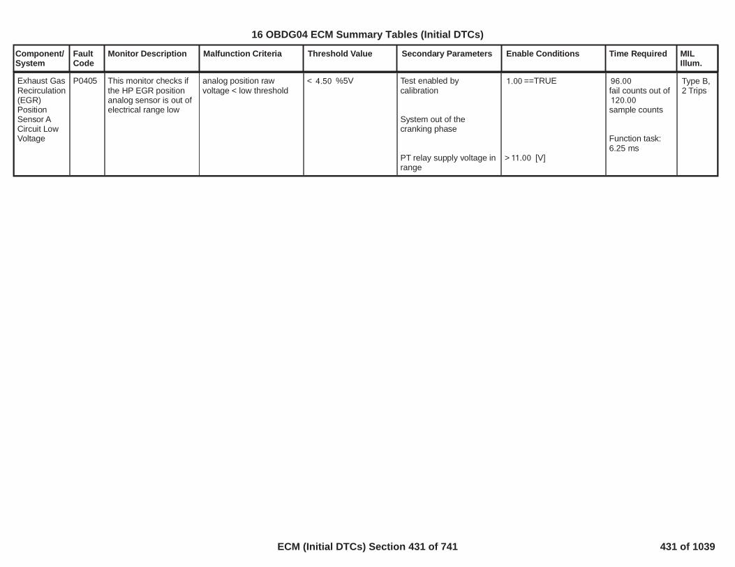
Component/System
FaultCode
Monitor Description Malfunction Criteria Threshold Value Secondary Parameters Enable Conditions Time Required MILIllum.
Exhaust GasRecirculation(EGR)PositionSensor ACircuit LowVoltage
P0405 This monitor checks ifthe HP EGR positionanalog sensor is out ofelectrical range low
analog position rawvoltage < low threshold
< %5V4.50 Test enabled bycalibration
System out of thecranking phase
PT relay supply voltage inrange
==TRUE1.00
> [V]11.00
96.00fail counts out of120.00sample counts
Function task:6.25 ms
Type B,2 Trips
432
16 OBDG04 ECM Summary Tables (Initial DTCs)
ECM (Initial DTCs) Section 431 of 741 431 of 1039

Component/System
FaultCode
Monitor Description Malfunction Criteria Threshold Value Secondary Parameters Enable Conditions Time Required MILIllum.
Exhaust GasRecirculation(EGR)PositionSensor ACircuit HighVoltage
P0406 This monitor checks ifthe HP EGRpositionanalog sensor is out ofelectrical range high
analog position rawvoltage > highthreshold
> %5V95.00 Test enabled bycalibration
System out of thecranking phase
PT relay supply voltage inrange
==TRUE1.00
> [V]11.00
96.00fail counts out of120.00sample counts
Function task:6.25 ms
Type B,2 Trips
433
16 OBDG04 ECM Summary Tables (Initial DTCs)
ECM (Initial DTCs) Section 432 of 741 432 of 1039

Component/System
FaultCode
Monitor Description Malfunction Criteria Threshold Value Secondary Parameters Enable Conditions Time Required MILIllum.
EGRTemperatureSensor2 CktLow
P040C Diagnose the EGRDown StreamTemperature sensorcircuit low
The ECM detects that themeasured resistance ofthe temperature sensor isout of range low.
Measured Resistanceof the Temperaturesensor < 146.65impedance
System supply voltageOutput driver iscommanded onIgnition switch is in crankor run position
> Volts11.00 40failures out of50samples100 ms /sample,continuous
Type B,2 Trips
434
16 OBDG04 ECM Summary Tables (Initial DTCs)
ECM (Initial DTCs) Section 433 of 741 433 of 1039

Component/System
FaultCode
Monitor Description Malfunction Criteria Threshold Value Secondary Parameters Enable Conditions Time Required MILIllum.
EGRTemperatureSensor2 CktHigh
P040D Diagnose the EGRDown StreamTemperature sensorcircuit high
The ECM detects that themeasured resistance ofthe temperature sensor isout of range high.
Measured Resistanceof the Temperaturesensor > 884.60impedance
System supply voltageOutput driver iscommanded onIgnition switch is in crankor run position
> Volts11.00 40failures out of50samples100 ms /sample,continuous
Type B,2 Trips
435
16 OBDG04 ECM Summary Tables (Initial DTCs)
ECM (Initial DTCs) Section 434 of 741 434 of 1039

Component/System
FaultCode
Monitor Description Malfunction Criteria Threshold Value Secondary Parameters Enable Conditions Time Required MILIllum.
EGRTemperatureSensor2 CktIntermittent/Erratic
P040E Detects a temperaturesensor that is showingerratic or intermittenttemperature readings
The absoluted value ofthe loop to loop (100 ms /sample) resistancechange of thetemperature sensor isgreater than the allowedrate of change.
Delta chage > 25.00impedance
System supply voltageOutput driver iscommanded onIgnition switch is in crankor run position
> Volts11.00 40failures out of50samples100 ms /sample,continuous
Type B,2 Trips
436
16 OBDG04 ECM Summary Tables (Initial DTCs)
ECM (Initial DTCs) Section 435 of 741 435 of 1039

Component/System
FaultCode
Monitor Description Malfunction Criteria Threshold Value Secondary Parameters Enable Conditions Time Required MILIllum.
EGRTemperatureSensor1 CktLow
P041C Diagnose the EGR UpStream Temperaturesensor circuit low
The ECM detects that themeasured resistance ofthe temperature sensor isout of range low.
Measured Resistanceof the Temperaturesensor < 146.65impedance
System supply voltageOutput driver iscommanded onIgnition switch is in crankor run position
> Volts11.00 40failures out of50samples100 ms /sample,continuous
Type B,2 Trips
437
16 OBDG04 ECM Summary Tables (Initial DTCs)
ECM (Initial DTCs) Section 436 of 741 436 of 1039

Component/System
FaultCode
Monitor Description Malfunction Criteria Threshold Value Secondary Parameters Enable Conditions Time Required MILIllum.
EGRTemperatureSensor1 CktHigh
P041D Diagnose the EGR UpStream Temperaturesensor circuit high
The ECM detects that themeasured resistance ofthe temperature sensor isout of range high.
Measured Resistanceof the Temperaturesensor > 884.60impedance
System supply voltageOutput driver iscommanded onIgnition switch is in crankor run position
> Volts11.00 40failures out of50samples100 ms /sample,continuous
Type B,2 Trips
438
16 OBDG04 ECM Summary Tables (Initial DTCs)
ECM (Initial DTCs) Section 437 of 741 437 of 1039

Component/System
FaultCode
Monitor Description Malfunction Criteria Threshold Value Secondary Parameters Enable Conditions Time Required MILIllum.
EGRTemperatureSensor1 CktIntermittent/Erratic
P041E Detects a temperaturesensor that is showingerratic or intermittenttemperature readings
The absoluted value ofthe loop to loop (100 ms /sample) resistancechange of thetemperature sensor isgreater than the allowedrate of change.
Delta chage > 25.00impedance
System supply voltageOutput driver iscommanded onIgnition switch is in crankor run position
> Volts11.00 40failures out of50samples100 ms /sample,continuous
Type B,2 Trips
439
16 OBDG04 ECM Summary Tables (Initial DTCs)
ECM (Initial DTCs) Section 438 of 741 438 of 1039

Component/System
FaultCode
Monitor Description Malfunction Criteria Threshold Value Secondary Parameters Enable Conditions Time Required MILIllum.
Exhaust GasRecirculationControlStuck Open
P042E This monitor checks ifthe HP EGR valve gotmechanically stuck in aposition more openthan what is requiredby the control
position tracking error(setpoint position -measured position) <negative threshold
AND
valve duty cycle <negative threshold
< [%]-8.00
AND
< [%]-80.00
Test enabled bycalibration
System out of thecranking phase
Position control in closedloop (no faults present onHP EGR position sensor,HP EGR valve, positiondeviation)
==TRUE1.00
==EGR_PstnShtOffReqFALSE
160.00fail counts out of200.00sample counts
Function task:6.25 ms
Type A,1 Trips
440
16 OBDG04 ECM Summary Tables (Initial DTCs)
ECM (Initial DTCs) Section 439 of 741 439 of 1039

Component/System
FaultCode
Monitor Description Malfunction Criteria Threshold Value Secondary Parameters Enable Conditions Time Required MILIllum.
Exhaust GasRecirculationControlStuckClosed
P042F This monitor checks ifthe HP EGR valve gotmechanically stuck in aposition more closedthan what is requiredby the control
position tracking error(setpoint position -measured position) >positive threshold
AND
valve duty cycle > positivethreshold
> [%]8.00
AND
> [%]80.00
Test enabled bycalibration
System out of thecranking phase
Position control in closedloop (no faults present onHP EGR position sensor,HP EGR valve, positiondeviation)
==TRUE1.00
==EGR_PstnShtOffReqFALSE
160.00fail counts out of200.00sample counts
Function task:6.25 ms
after
96.00fail counts out of120.00sample counts
Function task:12.5 ms
Type A,1 Trips
441
16 OBDG04 ECM Summary Tables (Initial DTCs)
ECM (Initial DTCs) Section 440 of 741 440 of 1039

Component/System
FaultCode
Monitor Description Malfunction Criteria Threshold Value Secondary Parameters Enable Conditions Time Required MILIllum.
Exhaust GasRecirculation(EGR)SolenoidControlCircuit LowVoltage
P0489 This monitor checks ifthe HP EGRcommands are shortedto ground
Error interface providedby HWIO
Error interfaceprovided by HWIO ==TRUE
Test enabled bycalibration
System out of thecranking phase
PT relay supply voltage inrange
Error interface providedby HWIO !=INDETERMINATE
==TRUE1.00
> [V]11.00
96.00fail counts out of120.00sample counts
Function task:12.5 ms
Type B,2 Trips
442
16 OBDG04 ECM Summary Tables (Initial DTCs)
ECM (Initial DTCs) Section 441 of 741 441 of 1039

Component/System
FaultCode
Monitor Description Malfunction Criteria Threshold Value Secondary Parameters Enable Conditions Time Required MILIllum.
Exhaust GasRecirculation(EGR)SolenoidControlCircuit HighVoltage
P0490 This monitor checks ifthe HP EGRcommands are shortedto power supply
Error interface providedby HWIO
Error interfaceprovided by HWIO ==TRUE
Test enabled bycalibration
System out of thecranking phase
PT relay supply voltage inrange
Error interface providedby HWIO !=INDETERMINATE
==TRUE1.00
> [V]11.00
96.00fail counts out of120.00sample counts
Function task:12.5 ms
Type B,2 Trips
443
16 OBDG04 ECM Summary Tables (Initial DTCs)
ECM (Initial DTCs) Section 442 of 741 442 of 1039

Component/System
FaultCode
Monitor Description Malfunction Criteria Threshold Value Secondary Parameters Enable Conditions Time Required MILIllum.
Exhaust GasRecirculationA ControlPositionExceededLearningLimit
P049D This monitor checks ifthe HP EGR positionanalog sensor has anoffset with respect tothe nominal positionwhere the valve doesthe learning procedure(fully closed)
analog position rawvoltage when the valve isin fully closed position <low threshold
OR
analog position rawvoltage when the valve isin fully closed position >highthreshold
< %5V16.40
OR
> %5V25.10
Test enabled bycalibration
IF AT KEY OFF:
Learning procedure at keyoff in fully closed positionhas been successfullycompleted (no faultspresent on HP EGRposition sensor, HP EGRvalve, HP EGR positiondeviation)
End Of Trip event haselapsed
IF IN NORMALRUNNING:
Learning procedure innormal running in fullyclosed position has beensuccessfully completed(no faults present on HPEGR position sensor, HPEGR valve, HP EGRposition deviation)
Key signal is on
==TRUE1.00
==EGR_PstnShtOffReqFALSE
==EGR_PstnShtOffReqFALSE
1.00fail counts out of1.00sample counts
Function task:in normalrunning and / orat key off
Type B,2 Trips
444
16 OBDG04 ECM Summary Tables (Initial DTCs)
ECM (Initial DTCs) Section 443 of 741 443 of 1039

Component/System
FaultCode
Monitor Description Malfunction Criteria Threshold Value Secondary Parameters Enable Conditions Time Required MILIllum.
PositiveCrankcaseVentilationHeaterControlCircuit /Open
P053A This DTC checks thecircuit for electricalintegrity duringoperation.Crankcase ventilationheater control pin openload.
Open circuitcommunicated by HWIO
Test performed byHWIO
GetHWIO_e_CrankcaseVentHtrOpen == 1
Test enabled bycalibration;
Key on or engine running(cranking excluded,Engine cranking equal to0);
Power train relay voltagein range;
Engine temperature isunder a calibrate-ablethreshold;
1.00
VePMDR_b_RunCrankActive == True;VeEMDR_b_EngModeCrank ==False;
> [V]11.00
< [°C]90.00
Time Counter:failures out20
of samples.40
Time Task 100[ms]
Type C,No SVS
445
16 OBDG04 ECM Summary Tables (Initial DTCs)
ECM (Initial DTCs) Section 444 of 741 444 of 1039

Component/System
FaultCode
Monitor Description Malfunction Criteria Threshold Value Secondary Parameters Enable Conditions Time Required MILIllum.
PositiveCrankcaseVentilationHeaterControlCircuit Low
P053B This DTC checks thecircuit for electricalintegrity duringoperation.Crankcase ventilationheater control pin shortto ground.
Short circuit to groundcommunicated by HWIO
Test performed byHWIO
(GetHWIO_e_CrankcaseVentHtrGsht==1)
Test enabled bycalibration;
Key on or engine running(cranking excluded,Engine cranking equal to0);
Power train relay voltagein range;
Engine temperature isunder a calibrate-ablethreshold;
1.00
VePMDR_b_RunCrankActive == True;VeEMDR_b_EngModeCrank ==False;
> [V]11.00
< [°C]90.00
Time Counter:failures out20
of samples.40
Time Task 100[ms]
Type C,No SVS
446
16 OBDG04 ECM Summary Tables (Initial DTCs)
ECM (Initial DTCs) Section 445 of 741 445 of 1039

Component/System
FaultCode
Monitor Description Malfunction Criteria Threshold Value Secondary Parameters Enable Conditions Time Required MILIllum.
PositiveCrankcaseVentilationHeaterControlCircuit High
P053C This DTC checks thecircuit for electricalintegrity duringoperation.Crankcase ventilationheater control pin shortto high voltage.
Short circuit to supplycommunicated by HWIO
Test performed byHWIO
(GetHWIO_e_CrankcaseVentHtrPsht==1)
Test enabled bycalibration;
Key on or engine running(cranking excluded,Engine cranking equal to0);
Power train relay voltagein range;
Engine temperature isunder a calibrate-ablethreshold;
1.00
VePMDR_b_RunCrankActive == True;VeEMDR_b_EngModeCrank ==False;
> [V]11.00
< [°C]90.00
Time Counter:failures out20
of samples.40
Time Task 100[ms]
Type C,No SVS
447
16 OBDG04 ECM Summary Tables (Initial DTCs)
ECM (Initial DTCs) Section 446 of 741 446 of 1039

Component/System
FaultCode
Monitor Description Malfunction Criteria Threshold Value Secondary Parameters Enable Conditions Time Required MILIllum.
Exhaust GasTemperatureSensorCircuit LowBank 1Sensor 1
P0545 This diagnosis verify ifthe exhaust gastemperature 1 (EGT1)sensor signal is shortedto GND
EGT1 output resistancevalue
< [Ohm]160 Test enabled bycalibration(TRUE--> enableFALSE --> disable)
and with
Engine cranking
and with
Battery voltage
and with
key on
[Boolean]1
== FALSE
> [V]11.00
== TRUE
10fail samples over
samples20
Function task:100ms
Type B,2 Trips
448
16 OBDG04 ECM Summary Tables (Initial DTCs)
ECM (Initial DTCs) Section 447 of 741 447 of 1039

Component/System
FaultCode
Monitor Description Malfunction Criteria Threshold Value Secondary Parameters Enable Conditions Time Required MILIllum.
Exhaust GasTemperatureSensorCircuit HighBank 1Sensor 1
P0546 This diagnosis verify ifthe exhaust gastemperature 1 (EGT1)signal is shorted topower supply or it is inopen circuit
EGT1 output resistancevalue
> [Ohm]900 Test enabled bycalibration(TRUE--> enableFALSE --> disable)
and with
Engine cranking
and with
Battery voltage
and with
key on
[Boolean]1
== FALSE
> [V]11.00
== TRUE
fail samples10over samples20
Function task:100ms
Type B,2 Trips
449
16 OBDG04 ECM Summary Tables (Initial DTCs)
ECM (Initial DTCs) Section 448 of 741 448 of 1039

Component/System
FaultCode
Monitor Description Malfunction Criteria Threshold Value Secondary Parameters Enable Conditions Time Required MILIllum.
Idle ControlSystem -FuelQuantityLower ThanExpected
P054E This DTC detects if thefuel quantity of thetorque forming pulsesis lower than theexpected fuel quantityrequest when theengine is idle.Depending oncombustion mode andgear, different maps offuel quantity thresholdscan be used. Each mapdepends on enginespeed and enginecoolant temperature
Depending onCombustion Mode
caseSCR Temp1:(transmission in Gear:Fuel quantity of the torqueforming pulses
transmission in Park/Neutral:Fuel quantity of the torqueforming pulses
)
caseSCR Temp2(transmission in Gear:Fuel quantity of the torqueforming pulses
< 0.5*P054E_IFM_MinFuelIdleT1_G[mm^3] depending onengine speed andengine coolanttemperature
< 0.5*P054E_IFM_MinFuelIdleT1_PN[mm^3] depending onengine speed andengine coolanttemperature
< 0.5*P054E_IFM_MinFuelIdleT2_G[mm^3] depending onengine speed andengine coolant
For enabling themonitor, all thefollowing conditionsmust be satisfiedcontinuously for morethan
Test enabled bycalibration
andcurrent gear
anddepending onGear SelectionCalibration =CeFULR_e_InGearNeutralPark(CeFULR_e_InGear:transmission
CeFULR_e_NeutralPark:transmission
CeFULR_e_InGearNeutralPark:transmission)
andengine speed
andengine speed
[s]5.00
[Boolean]1.00
unchanged
in gear
in park/neutral
in gear and in park neutral
> hysteresis( ,511.00+ )[rpm]511.00 0.00
<hysteresis( ,1,560.00+ )[rpm]1,560.00 0.00
failures200.00out of 255.00samples
1 sample everycylinder firingevent
Type B,2 Trips
450
16 OBDG04 ECM Summary Tables (Initial DTCs)
ECM (Initial DTCs) Section 449 of 741 449 of 1039

Component/System
FaultCode
Monitor Description Malfunction Criteria Threshold Value Secondary Parameters Enable Conditions Time Required MILIllum.
transmission in Park/Neutral:Fuel quantity of the torqueforming pulses
)
caseSCR Temp3(transmission in Gear:Fuel quantity of the torqueforming pulses
transmission in Park/Neutral:Fuel quantity of the torqueforming pulses
)
caseHC unloading drivingand park/neutral
temperature
< 0.5*P054E_IFM_MinFuelIdleT2_PN[mm^3] depending onengine speed andengine coolanttemperature
< 0.5*P054E_IFM_MinFuelIdleT3_G[mm^3] depending onengine speed andengine coolanttemperature
< 0.5*P054E_IFM_MinFuelIdleT3_PN[mm^3] depending onengine speed andengine coolanttemperature
and(OBD Coolant EnableCriteria
OR
engine coolanttemperature
)
andoutside air temperature
andvehicle speed
andenabled in the combustionmode
andAccelerator PedalPosition
andEngine running
andRun Crank voltage
andNo active DTC's:
Depending on theOAT Source Calibration
== TRUE
> hysteresis( ,-21.00) [°C]-20.00
> hysteresis( ,-21.00) [°C]-20.00
< [kph]3.00
P054E_IFM_CombModesEnbl
<= [%]0.05
-
>= [V]11.00
451
16 OBDG04 ECM Summary Tables (Initial DTCs)
ECM (Initial DTCs) Section 450 of 741 450 of 1039

Component/System
FaultCode
Monitor Description Malfunction Criteria Threshold Value Secondary Parameters Enable Conditions Time Required MILIllum.
(HCS_DeHC_Drive ||HCS_DeHC_Park):(transmission in Gear:Fuel quantity of the torqueforming pulses
transmission in Park/Neutral:Fuel quantity of the torqueforming pulses
)
default:(transmission in Gear:Fuel quantity of the torqueforming pulses
transmission in Park/Neutral:Fuel quantity of the torqueforming pulses
< 0.5*P054E_IFM_MinFuelIdleHC_G[mm^3] depending onengine speed andengine coolanttemperature
< 0.5*P054E_IFM_MinFuelIdleHC_PN[mm^3] depending onengine speed andengine coolanttemperature
< 0.5*P054E_IFM_MinFuelIdleC1_G[mm^3] depending onengine speed andengine coolanttemperature
< 0.5*
=CeOATR_e_ECM_OAT_Sensor(CeOATR_e_NonOBD_NonECM_NonVICM:
default:)
OAT_OAT_SnsrNonEmissFA
OAT_PtEstFiltFA
CrankSensor_TFTKO
ECT_Sensor_FA
Transmission EstimatedGear Validity
VehicleSpeedSensor_FA
AcceleratorPedalFailure
(FUL_GenericInjSysFAANDFUL_GenericInjSysFlt)
452
16 OBDG04 ECM Summary Tables (Initial DTCs)
ECM (Initial DTCs) Section 451 of 741 451 of 1039

Component/System
FaultCode
Monitor Description Malfunction Criteria Threshold Value Secondary Parameters Enable Conditions Time Required MILIllum.
)
P054E_IFM_MinFuelIdleC1_PN[mm^3] depending onengine speed andengine coolanttemperature
453
16 OBDG04 ECM Summary Tables (Initial DTCs)
ECM (Initial DTCs) Section 452 of 741 452 of 1039

Component/System
FaultCode
Monitor Description Malfunction Criteria Threshold Value Secondary Parameters Enable Conditions Time Required MILIllum.
Idle ControlSystem -FuelQuantityHigher ThanExpected
P054F This DTC detects if thefuel quantity of thetorque forming pulse ishigher than theexpected fuel quantityrequest when theengine is idle.Depending oncombustion mode andgear, different maps offuel quantity thresholdscan be used. Each mapdepends on enginespeed and enginecoolant temperature
Depending onCombustion Mode
caseSCR Temp1:{transmission in Gear:Fuel quantity of the torqueforming pulses
transmission in Park/Neutral:Fuel quantity of the torqueforming pulses
}
caseSCR Temp2{transmission in Gear:Fuel quantity of the torqueforming pulses
> 1.5*P054F_IFM_MaxFuelIdleT1_G[mm^3] depending onengine speed andengine coolanttemperature
> 1.5*P054F_IFM_MaxFuelIdleT1_PN[mm^3] depending onengine speed andengine coolanttemperature
> 1.5*P054F_IFM_MaxFuelIdleT2_G[mm^3] depending onengine speed andengine coolanttemperature
For enabling themonitor, all thefollowing conditionsmust be satisfiedcontinuously for morethan
Test enabled bycalibration
andcurrent gear
anddepending onGear SelectionCalibration =CeFULR_e_InGearNeutralPark{CeFULR_e_InGear:transmission
CeFULR_e_NeutralPark:transmission
CeFULR_e_InGearNeutralPark:transmission}
andengine speed
andengine speed
and
[s]5.00
[Boolean]1.00
unchanged
in gear
in park/neutral
in gear and in park neutral
> hysteresis( ,511.00+ ) [rpm]511.00 0.00
< hysteresis( ,1,560.00+ ) [rpm]1,560.00 0.00
failures200.00out of 255.00samples
1 sample everycylinder firingevent
Type B,2 Trips
454
16 OBDG04 ECM Summary Tables (Initial DTCs)
ECM (Initial DTCs) Section 453 of 741 453 of 1039

Component/System
FaultCode
Monitor Description Malfunction Criteria Threshold Value Secondary Parameters Enable Conditions Time Required MILIllum.
transmission in Park/Neutral:Fuel quantity of the torqueforming pulses
}
caseSCR Temp3{transmission in Gear:Fuel quantity of the torqueforming pulses
transmission in Park/Neutral:Fuel quantity of the torqueforming pulses
}
caseHC unloading drivingand park/neutral(HCS_DeHC_Drive ||
> 1.5*P054F_IFM_MaxFuelIdleT2_PN[mm^3] depending onengine speed andengine coolanttemperature
> 1.5*P054F_IFM_MaxFuelIdleT3_G[mm^3] depending onengine speed andengine coolanttemperature
> 1.5*P054F_IFM_MaxFuelIdleT3_PN[mm^3] depending onengine speed andengine coolanttemperature
{OBD Coolant EnableCriteria
ORengine coolanttemperature
}
andoutside air temperature
andvehicle speed
andenabled in the combustionmode
andAccelerator PedalPosition
andEngine running
andRun Crank voltage
andNo active DTC's:
Depending on theOAT Source Calibration=CeOATR_e_ECM_OAT_Sensor{CeOATR_e_NonOBD_NonECM_NonVICM:
== TRUE
> hysteresis( ,-21.00) [°C]-20.00
> hysteresis( ,-21.00) [°C]-20.00
< [kph]3.00
P054E_IFM_CombModesEnbl
<= [%]0.05
-
>= [V]11.00
455
16 OBDG04 ECM Summary Tables (Initial DTCs)
ECM (Initial DTCs) Section 454 of 741 454 of 1039

Component/System
FaultCode
Monitor Description Malfunction Criteria Threshold Value Secondary Parameters Enable Conditions Time Required MILIllum.
HCS_DeHC_Park):{transmission in Gear:Fuel quantity of the torqueforming pulses
transmission in Park/Neutral:Fuel quantity of the torqueforming pulses
}
default:{transmission in Gear:Fuel quantity of the torqueforming pulses
transmission in Park/Neutral:Fuel quantity of the torqueforming pulses
> 1.5*P054F_IFM_MaxFuelIdleHC_G[mm^3] depending onengine speed andengine coolanttemperature
> 1.5*P054F_IFM_MaxFuelIdleHC_PN[mm^3] depending onengine speed andengine coolanttemperature
> 1.5*P054F_IFM_MaxFuelIdleC1_G[mm^3] depending onengine speed andengine coolanttemperature
> 1.5*P054F_IFM_MaxFuelIdleC1_PN[mm^3] depending onengine speed and
default:}
OAT_OAT_SnsrNonEmissFA
OAT_PtEstFiltFA
CrankSensor_TFTKO
ECT_Sensor_FA
Transmission EstimatedGear Validity
VehicleSpeedSensor_FA
AcceleratorPedalFailure
(FUL_GenericInjSysFAANDFUL_GenericInjSysFlt)
456
16 OBDG04 ECM Summary Tables (Initial DTCs)
ECM (Initial DTCs) Section 455 of 741 455 of 1039

Component/System
FaultCode
Monitor Description Malfunction Criteria Threshold Value Secondary Parameters Enable Conditions Time Required MILIllum.
}
engine coolanttemperature
457
16 OBDG04 ECM Summary Tables (Initial DTCs)
ECM (Initial DTCs) Section 456 of 741 456 of 1039

Component/System
FaultCode
Monitor Description Malfunction Criteria Threshold Value Secondary Parameters Enable Conditions Time Required MILIllum.
InternalControlModule FuelInjectorControlPerformance
P062B This DTC Diagnosesthe internal fuel injectorcontrol module circuitfor circuit faults. Thefollowing check areperformed:- Chip initialization- Boost voltage- chip test- Code and Parameter- SPI error (SPIcommunication failed)
Driver Status
OR(Driver Status
for a number of samples)
== FAILED (chip testnot passed OR Wrongdownload of microcodeOR SPI error)
== NOT INITIALIZED(chip not initialized ORBoost Voltage < 52 [V])
> samples10
Test enabled bycalibration;
andBattery voltage
andKey ON
andEngine is not cranking
andBoost Voltage hasachieved (at least onetime)
== [Boolean]1
> [V]11.00
-
-
[V]52.00
failures out of4samples8
12.5 ms / sampleContinuous
Type A,1 Trips
458
16 OBDG04 ECM Summary Tables (Initial DTCs)
ECM (Initial DTCs) Section 457 of 741 457 of 1039

Component/System
FaultCode
Monitor Description Malfunction Criteria Threshold Value Secondary Parameters Enable Conditions Time Required MILIllum.
Fuel InjectorDriver CircuitPerformanceBank 1
P062D This DTC detects ifthere is:open circuit of thepower supply line of theinjectororBoost voltage faultorECU internal faultThe monitoringdetermines if the boostvoltage is above athreshold or belowanother threshlod withhysteresis
Internal ECU BoostVoltage
> [V]75.00
OR
< hysteresis( ,52.00) [V]53.00
Test enabled bycalibration;
andBattery voltage
andKey ON
andEngine is not cranking
== [Boolean]1
> [V]11.00
-
-
failures out14of samples20
6.25 ms/sampleContinuous
Type A,1 Trips
459
16 OBDG04 ECM Summary Tables (Initial DTCs)
ECM (Initial DTCs) Section 458 of 741 458 of 1039

Component/System
FaultCode
Monitor Description Malfunction Criteria Threshold Value Secondary Parameters Enable Conditions Time Required MILIllum.
Cylinder 1Glow PlugCircuit Low
P066A This DTC checks thecircuit for electricalintegrity duringoperation.Glow plug 1 pin short toground.
Cylinder 1 Glow PlugCircuit Low
Test performed by HWIO
Fault present reportedby HWIO
VaGLOO_e_GlowPlugGshtErr{}{CiEPSR_CylinderA}==True
Test enabled bycalibration;
Key on and enginerunning (crankingexcluded);
Battery voltage in range;
No faults detected onglow plug system supply;
Duty cycle above acalibratable threshold;
Diagnostic system is notdisabled;
[boolean]1.00
VePMDR_b_RunCrankActive = TRUE;VeEMDR_b_EngModeCrank = FALSE;
VeLVTR_b_RunCrankIgnInRange = TRUE;
GLO_GlowPlugSplyVoltCktTFTKO
[%]2.00
VeDRER_DiagSystemDsbl = FALSE;
fail10.00samples
over
samples20.00
Time task: 100[ms]
Type B,2 Trips+ glowlamp ON
460
16 OBDG04 ECM Summary Tables (Initial DTCs)
ECM (Initial DTCs) Section 459 of 741 459 of 1039

Component/System
FaultCode
Monitor Description Malfunction Criteria Threshold Value Secondary Parameters Enable Conditions Time Required MILIllum.
Cylinder 1Glow PlugCircuit High
P066B This DTC checks thecircuit for electricalintegrity duringoperation.
Glow plug 1 pin short tohigh voltage.
Cylinder 1 Glow PlugCircuit High
Test performed by HWIO
Fault present reportedby HWIO
VaGLOO_e_GlowPlugPsht{CiEPSR_CylinderA}==True
Test enabled bycalibration;
Key on and enginerunning (crankingexcluded);
Battery voltage in range;
No faults detected onglow plug system supply;
Diagnostic system is notdisabled;
[boolean]1.00
VePMDR_b_RunCrankActive = TRUE;VeEMDR_b_EngModeCrank = FALSE;
VeLVTR_b_RunCrankIgnInRange = TRUE;
GLO_GlowPlugSplyVoltCktTFTKO
VeDRER_DiagSystemDsbl = FALSE;
fail10.00samples
over
samples20.00
Time task: 100[ms]
Type B,2 Trips+ glowlamp ON
461
16 OBDG04 ECM Summary Tables (Initial DTCs)
ECM (Initial DTCs) Section 460 of 741 460 of 1039

Component/System
FaultCode
Monitor Description Malfunction Criteria Threshold Value Secondary Parameters Enable Conditions Time Required MILIllum.
Cylinder 2Glow PlugCircuit Low
P066C This DTC checks thecircuit for electricalintegrity duringoperation.Glow plug 2 pin short toground.
Cylinder 2 Glow PlugCircuit Low
Test performed by HWIO
Fault present reportedby HWIO
VaGLOO_e_GlowPlugGshtErr{CiEPSR_CylinderB}==True
Test enabled bycalibration;
Key on and enginerunning (crankingexcluded);
Battery voltage in range;
No faults detected onglow plug system supply;
Duty cycle above acalibratable threshold;
Diagnostic system is notdisable;
[boolean]1.00
VePMDR_b_RunCrankActive = TRUE;VeEMDR_b_EngModeCrank = FALSE;
VeLVTR_b_RunCrankIgnInRange = TRUE;
GLO_GlowPlugSplyVoltCktTFTKO
[%]2.00
VeDRER_DiagSystemDsbl = FALSE;
fail10.00samples
over
samples20.00
Time task: 100[ms]
Type B,2 Trips+ glowlamp ON
462
16 OBDG04 ECM Summary Tables (Initial DTCs)
ECM (Initial DTCs) Section 461 of 741 461 of 1039

Component/System
FaultCode
Monitor Description Malfunction Criteria Threshold Value Secondary Parameters Enable Conditions Time Required MILIllum.
Cylinder 2Glow PlugCircuit High
P066D This DTC checks thecircuit for electricalintegrity duringoperation.
Glow plug 2 pin short tohigh voltage.
Cylinder 2 Glow PlugCircuit High
Test performed by HWIO
Fault present reportedby HWIO
VaGLOO_e_GlowPlugPsht{CiEPSR_CylinderB}==True
Test enabled bycalibration;
Key on and enginerunning (crankingexcluded);
Battery voltage in range;
No faults detected onglow plug system supply;
Diagnostic system is notdisabled;
[boolean]1.00
VePMDR_b_RunCrankActive = TRUE;VeEMDR_b_EngModeCrank = FALSE;
VeLVTR_b_RunCrankIgnInRange = TRUE;
GLO_GlowPlugSplyVoltCktTFTKO
VeDRER_DiagSystemDsbl = FALSE;
fail10.00samples
over
samples20.00
Time task: 100[ms]
Type B,2 Trips+ glowlamp ON
463
16 OBDG04 ECM Summary Tables (Initial DTCs)
ECM (Initial DTCs) Section 462 of 741 462 of 1039

Component/System
FaultCode
Monitor Description Malfunction Criteria Threshold Value Secondary Parameters Enable Conditions Time Required MILIllum.
Cylinder 3Glow PlugCircuit Low
P066E This DTC checks thecircuit for electricalintegrity duringoperation.Glow plug 3 pin short toground.
Cylinder 3 Glow PlugCircuit Low
Test performed by HWIO
Fault present reportedby HWIO
VaGLOO_e_GlowPlugGshtErr{CiEPSR_CylinderC}==True
Test enabled bycalibration;
Key on and enginerunning (crankingexcluded);
Battery voltage in range;
No faults detected onglow plug system supply;
Duty cycle above acalibratable threshold;
Diagnostic system is notdisable;
[boolean]1.00
VePMDR_b_RunCrankActive = TRUE;VeEMDR_b_EngModeCrank = FALSE;
VeLVTR_b_RunCrankIgnInRange = TRUE;
GLO_GlowPlugSplyVoltCktTFTKO
[%]2.00
VeDRER_DiagSystemDsbl = FALSE;
fail10.00samples
over
samples20.00
Time task: 100[ms]
Type B,2 Trips+ glowlamp ON
464
16 OBDG04 ECM Summary Tables (Initial DTCs)
ECM (Initial DTCs) Section 463 of 741 463 of 1039

Component/System
FaultCode
Monitor Description Malfunction Criteria Threshold Value Secondary Parameters Enable Conditions Time Required MILIllum.
Cylinder 3Glow PlugCircuit High
P066F This DTC checks thecircuit for electricalintegrity duringoperation.
Glow plug 3 pin short tohigh voltage.
Cylinder 3 Glow PlugCircuit High
Test performed by HWIO
Fault present reportedby HWIO
VaGLOO_e_GlowPlugPsht{CiEPSR_CylinderC}==True
Test enabled bycalibration;
Key on and enginerunning (crankingexcluded);
Battery voltage in range;
No faults detected onglow plug system supply;
Diagnostic system is notdisabled;
[boolean]1.00
VePMDR_b_RunCrankActive = TRUE;VeEMDR_b_EngModeCrank = FALSE;
VeLVTR_b_RunCrankIgnInRange = TRUE;
GLO_GlowPlugSplyVoltCktTFTKO
VeDRER_DiagSystemDsbl = FALSE;
fail10.00samples
over
samples20.00
Time task: 100[ms]
Type B,2 Trips+ glowlamp ON
465
16 OBDG04 ECM Summary Tables (Initial DTCs)
ECM (Initial DTCs) Section 464 of 741 464 of 1039

Component/System
FaultCode
Monitor Description Malfunction Criteria Threshold Value Secondary Parameters Enable Conditions Time Required MILIllum.
Cylinder 1Glow PlugCircuit/Open
P0671 This DTC checks thecircuit for electricalintegrity duringoperation.
Glow plug 1 pin openload.
Cylinder 1 Glow PlugCircuit Open
Test performed by HWIO
Fault present reportedby HWIO
VaGLOO_e_GlowPlugOpen{CiEPSR_CylinderA}==True
Test enabled bycalibration;
Key on and enginerunning (crankingexcluded);
Battery voltage in range;
No faults detected onglow plug system supply;
Duty cycle above acalibratable threshold;
Diagnostic system is notdisabled;
[boolean]1.00
VePMDR_b_RunCrankActive = TRUE;VeEMDR_b_EngModeCrank = FALSE;
VeLVTR_b_RunCrankIgnInRange = TRUE;
GLO_GlowPlugSplyVoltCktTFTKO
[%]2.00
VeDRER_DiagSystemDsbl = FALSE;
fail10.00samples
over
samples20.00
Time task: 100[ms]
Type B,2 Trips+ glowlamp ON
466
16 OBDG04 ECM Summary Tables (Initial DTCs)
ECM (Initial DTCs) Section 465 of 741 465 of 1039

Component/System
FaultCode
Monitor Description Malfunction Criteria Threshold Value Secondary Parameters Enable Conditions Time Required MILIllum.
Cylinder 2Glow PlugCircuit/Open
P0672 This DTC checks thecircuit for electricalintegrity duringoperation.
Glow plug 2 pin openload.
Cylinder 2 Glow PlugCircuit Open
Test performed by HWIO
Fault present reportedby HWIO
VaGLOO_e_GlowPlugOpen{CiEPSR_CylinderB}==True
Test enabled bycalibration;
Key on and enginerunning (crankingexcluded);
Battery voltage in range;
No faults detected onglow plug system supply;
Duty cycle above acalibratable threshold;
Diagnostic system is notdisabled;
[boolean]1.00
VePMDR_b_RunCrankActive = TRUE;VeEMDR_b_EngModeCrank = FALSE;
VeLVTR_b_RunCrankIgnInRange = TRUE;
GLO_GlowPlugSplyVoltCktTFTKO
[%]2.00
VeDRER_DiagSystemDsbl = FALSE;
fail10.00samples
over
samples20.00
Time task: 100[ms]
Type B,2 Trips+ glowlamp ON
467
16 OBDG04 ECM Summary Tables (Initial DTCs)
ECM (Initial DTCs) Section 466 of 741 466 of 1039

Component/System
FaultCode
Monitor Description Malfunction Criteria Threshold Value Secondary Parameters Enable Conditions Time Required MILIllum.
Cylinder 3Glow PlugCircuit/Open
P0673 This DTC checks thecircuit for electricalintegrity duringoperation.
Glow plug 3 pin openload.
Cylinder 3 Glow PlugCircuit Open
Test performed by HWIO
Fault present reportedby HWIO
VaGLOO_e_GlowPlugOpen{CiEPSR_CylinderC}==True
Test enabled bycalibration;
Key on and enginerunning (crankingexcluded);
Battery voltage in range;
No faults detected onglow plug system supply;
Duty cycle above acalibratable threshold;
Diagnostic system is notdisabled;
[boolean]1.00
VePMDR_b_RunCrankActive = TRUE;VeEMDR_b_EngModeCrank = FALSE;
VeLVTR_b_RunCrankIgnInRange = TRUE;
GLO_GlowPlugSplyVoltCktTFTKO
[%]2.00
VeDRER_DiagSystemDsbl = FALSE;
fail10.00samples
over
samples20.00
Time task: 100[ms]
Type B,2 Trips+ glowlamp ON
468
16 OBDG04 ECM Summary Tables (Initial DTCs)
ECM (Initial DTCs) Section 467 of 741 467 of 1039

Component/System
FaultCode
Monitor Description Malfunction Criteria Threshold Value Secondary Parameters Enable Conditions Time Required MILIllum.
Cylinder 4Glow PlugCircuit/Open
P0674 This DTC checks thecircuit for electricalintegrity duringoperation.
Glow plug 4 pin openload.
Cylinder 3 Glow PlugCircuit Open
Test performed by HWIO
Fault present reportedby HWIO
VaGLOO_e_GlowPlugOpen{CiEPSR_CylinderD}==True
Test enabled bycalibration;
Key on and enginerunning (crankingexcluded);
Battery voltage in range;
No faults detected onglow plug system supply;
Duty cycle above acalibratable threshold;
Diagnostic system is notdisabled;
[boolean]1.00
VePMDR_b_RunCrankActive = TRUE;VeEMDR_b_EngModeCrank = FALSE;
VeLVTR_b_RunCrankIgnInRange = TRUE;
GLO_GlowPlugSplyVoltCktTFTKO
[%]2.00
VeDRER_DiagSystemDsbl = FALSE;
fail10.00samples
over
samples20.00
Time task: 100[ms]
Type B,2 Trips+ glowlamp ON
469
16 OBDG04 ECM Summary Tables (Initial DTCs)
ECM (Initial DTCs) Section 468 of 741 468 of 1039

Component/System
FaultCode
Monitor Description Malfunction Criteria Threshold Value Secondary Parameters Enable Conditions Time Required MILIllum.
Cylinder 4Glow PlugCircuit Low
P067A This DTC checks thecircuit for electricalintegrity duringoperation.
Glow plug 4 pin short toground.
Cylinder 4 Glow PlugCircuit Low
Test performed by HWIO
Fault present reportedby HWIO
VaGLOO_e_GlowPlugGshtErr{CiEPSR_CylinderD}==True
Test enabled bycalibration;
Key on and enginerunning (crankingexcluded);
Battery voltage in range;
No faults detected onglow plug system supply;
Duty cycle above acalibratable threshold;
Diagnostic system is notdisable;
[boolean]1.00
VePMDR_b_RunCrankActive = TRUE;VeEMDR_b_EngModeCrank = FALSE;
VeLVTR_b_RunCrankIgnInRange = TRUE;
GLO_GlowPlugSplyVoltCktTFTKO
[%]2.00
VeDRER_DiagSystemDsbl = FALSE;
fail10.00samples
over
samples20.00
Time task: 100[ms]
Type B,2 Trips+ glowlamp ON
470
16 OBDG04 ECM Summary Tables (Initial DTCs)
ECM (Initial DTCs) Section 469 of 741 469 of 1039

Component/System
FaultCode
Monitor Description Malfunction Criteria Threshold Value Secondary Parameters Enable Conditions Time Required MILIllum.
Cylinder 4Glow PlugCircuit High
P067B This DTC checks thecircuit for electricalintegrity duringoperation.
Glow plug 4 pin short tohigh voltage.
Cylinder 4 Glow PlugCircuit High
Test performed by HWIO
Fault present reportedby HWIO
VaGLOO_e_GlowPlugPsht{CiEPSR_CylinderD}==True
Test enabled bycalibration;
Key on and enginerunning (crankingexcluded);
Battery voltage in range;
No faults detected onglow plug system supply;
Diagnostic system is notdisabled;
[boolean]1.00
VePMDR_b_RunCrankActive = TRUE;VeEMDR_b_EngModeCrank = FALSE;
VeLVTR_b_RunCrankIgnInRange = TRUE;
GLO_GlowPlugSplyVoltCktTFTKO
VeDRER_b_DiagSystemDsbl = FALSE;
fail10.00samples
over
samples20.00
Time task: 100[ms]
Type B,2 Trips+ glowlamp ON
471
16 OBDG04 ECM Summary Tables (Initial DTCs)
ECM (Initial DTCs) Section 470 of 741 470 of 1039

Component/System
FaultCode
Monitor Description Malfunction Criteria Threshold Value Secondary Parameters Enable Conditions Time Required MILIllum.
ReductantPump DriverHighTemperature
P103F This diagnosis verifiesthat the Motor MosfetDriver Temperature istoo High
Motor Mosfet DriverTemperature too HighError status == FAULT
VeSCRR_e_PmpDrvrHiTemp == FAULT
Test enabled bycalibration
Key on (OR enginerunning)
Engine is not cranking
Battery voltage
No loss of CANcommunication
Motor Mosfet DriverTemperature too HighError status provided byDEF control moduledifferent fromINDETERMINATE
[Boolean]1.00
(VePMDR_b_RunCrankActive==TRUE)
(VeEMDR_b_EngModeCrank == FALSE)
> [V]11.00(VeLVTR_b_PT_RelayInRange== TRUE)
U010E, LostCommunication WithReductant Control Module(SCR)(GetCANR_b_LostComm_FltN = FALSE)
VeSCRR_e_PmpDrvrHiTemp != Indeterminate)
40.00
failuresout of
50.00
samples
Time basis =100ms/sample
Type A,1 Trips
472
16 OBDG04 ECM Summary Tables (Initial DTCs)
ECM (Initial DTCs) Section 471 of 741 471 of 1039

Component/System
FaultCode
Monitor Description Malfunction Criteria Threshold Value Secondary Parameters Enable Conditions Time Required MILIllum.
ReductantPump AControlCircuitShorted
P1040 This diagnosis verifiesthat the DEF pumpphases are shorted
Motor Pump PhasesShorted Error statusprovided by DEF controlmodule == FAULT
VeSCRR_e_PmpMtrShorted==FAULT
Test enabled bycalibration
Key on (OR enginerunning)
Engine is not cranking
Battery voltage
No loss of CANcomunication
Motor Pump PhasesShorted Error statusprovided by DEF controlmodule different fromindeterminate
1.00
(VePMDR_b_RunCrankActive==TRUE)
VeEMDR_b_EngModeCrank == FALSE
> [V]11.00(VeLVTR_b_PT_RelayInRange== TRUE)
U010E, LostCommunication WithReductant Control Module(SCR)(GetCANR_b_LostComm_FltN= FALSE)
(VeSCRR_e_PmpMtrShorted != Indeterminate)
20.00
failuresout of
samples25.00
Time basis =100ms/sample
Type A,1 Trips
473
16 OBDG04 ECM Summary Tables (Initial DTCs)
ECM (Initial DTCs) Section 472 of 741 472 of 1039

Component/System
FaultCode
Monitor Description Malfunction Criteria Threshold Value Secondary Parameters Enable Conditions Time Required MILIllum.
ReductantInjectionValve SupplyVoltageCircuit LowBank 1 Unit1
P1048 This diagnosis verifiesif a DEF dosing valvehigh side short toground occurred
HWIO interfaceDEFMV_ENABLE_GROUND_SHORT = Fault
VeHWIO_e_DEFMV_Enbl_Gsht ==CeSCRR_e_Fault
Test enabled bycalibration
Key on (OR enginerunning)
Engine is not cranking
Battery voltage
HWIO interfaceDEFMV_ENABLE_GROUND_SHORT different fromINDETERMINATE
1.00
(VePMDR_b_RunCrankActive == TRUE)
(VeEMDR_b_EngModeCrank == FALSE)
> [V]11.00(VeLVTR_b_PT_RelayInRange== TRUE)
(VeHWIO_e_DEFMV_Enbl_Gsht !=CeSCRR_e_Indeterminate)
30.00
failuresout of
60.00
samples
Time basis =100ms/sample
Type A,1 Trips
474
16 OBDG04 ECM Summary Tables (Initial DTCs)
ECM (Initial DTCs) Section 473 of 741 473 of 1039

Component/System
FaultCode
Monitor Description Malfunction Criteria Threshold Value Secondary Parameters Enable Conditions Time Required MILIllum.
ReductantInjectionValve SupplyVoltageCircuit HighBank 1 Unit1
P1049 This diagnosis verifiesif a DEF dosing valvehigh side short topower occurred
HWIO interfaceDEFMV_ENABLE_POWER_SHORT = Fault
VeHWIO_e_DEFMV_Enbl_Psht ==CeSCRR_e_Fault
Test enabled bycalibration
Key on (OR enginerunning)
Engine is not cranking
Battery voltage
HWIO interfaceDEFMV_ENABLE_POWER_SHORT different fromINDETERMINATE
1.00
(VePMDR_b_RunCrankActive == TRUE)
(VeEMDR_b_EngModeCrank == FALSE)
> [V]11.00(VeLVTR_b_PT_RelayInRange== TRUE)
(VeHWIO_e_DEFMV_Enbl_Psht !=CeSCRR_e_Indeterminate)
30.00
failures out of
60.00
samples
Time basis =100ms/sample
Type A,1 Trips
475
16 OBDG04 ECM Summary Tables (Initial DTCs)
ECM (Initial DTCs) Section 474 of 741 474 of 1039

Component/System
FaultCode
Monitor Description Malfunction Criteria Threshold Value Secondary Parameters Enable Conditions Time Required MILIllum.
ReductantLevelSensor-InvalidRange
P1050 This diagnosis verifiesthat the DEF levelsensor raw signal is notwithin plausible range
DEF level sensor rawvalue is not withincalibrated range (fordiscrete level sensor,each discrete level has itsplausible range)
NOT(VeSCRR_Pct_DEF_LevelRaw > AND2.00VeSCRR_Pct_DEF_LevelRaw < )5.50
AND
NOT(VeSCRR_Pct_DEF_LevelRaw > AND17.30VeSCRR_Pct_DEF_LevelRaw < )22.00
AND
NOT(VeSCRR_Pct_DEF_LevelRaw > AND32.90VeSCRR_Pct_DEF_LevelRaw < )38.80
AND
NOT(VeSCRR_Pct_DEF_LevelRaw > AND63.10VeSCRR_Pct_DEF_LevelRaw < )69.40
Test enabled bycalibration
Key on (OR enginerunning)
Engine is not cranking
Battery voltage
No loss of CANcommunication
No electrical faults onDEF level sensor
Discrete Level sensorused
1.00
(VePMDR_b_RunCrankActive==TRUE)
(VeEMDR_b_EngModeCrank == FALSE)
> [V]11.00(VeLVTR_b_RunCrankIgnInRange == TRUE)
U010E, LostCommunication WithReductant Control Module(SCR)(GetCANR_b_LostComm_FltN= FALSE)
SCR_DEFLS_ElecFltSt== FALSE
CeSCRI_e_DEF_LvlSnsrDiscrete ==CeSCRI_e_DEF_LvlSnsrDiscrete
40.00
failures out of
50.00
samples
Time basis =100ms/sample
Type B,2 Trips
476
16 OBDG04 ECM Summary Tables (Initial DTCs)
ECM (Initial DTCs) Section 475 of 741 475 of 1039

Component/System
FaultCode
Monitor Description Malfunction Criteria Threshold Value Secondary Parameters Enable Conditions Time Required MILIllum.
ReductantHeater 1Driver OverTemperatureFault
P1051 This diagnosis verifiesif the driver of the DEFtank heater is affectedby overtemperature
Tank Heater driver overtemperature flag reports afail
VeSCRR_e_HeatA_OverTemp ==CeSCRR_e_fault
Test enabled bycalibration
Temperature used by theheating strategy to switchon the heaters < threshold
Battery voltage
Key on (OR enginerunning)
Engine is not cranking
No loss of CANcommunication
DEF Temperature sensornot in fault
Tank Heater driver overtemperature flag differentfrom INDETERMINATE
1.00
min(VeOATR_T_OutsideAirNonEmiss,VeSCRC_T_DEF_Tank) <60.00
> [V]11.00(VeLVTR_b_RunCrankIgnInRange == TRUE)
(VePMDR_b_RunCrankActive==TRUE)
(VeEMDR_b_EngModeCrank == FALSE)
U010E, LostCommunication WithReductant Control Module(SCR)(GetCANR_b_LostComm_FltN= FALSE)
==SCR_DEFTS_FAFALSE
VeSCRR_e_HeatA_OverTemp !=CeSCRR_e_Indeterminate
8.00
failures out of
10.00
samples
Time basis =500ms/sample
Type A,1 Trips
477
16 OBDG04 ECM Summary Tables (Initial DTCs)
ECM (Initial DTCs) Section 476 of 741 476 of 1039

Component/System
FaultCode
Monitor Description Malfunction Criteria Threshold Value Secondary Parameters Enable Conditions Time Required MILIllum.
ReductantHeater 2Driver OverTemperatureFault
P1052 This diagnosis verifiesif the driver of the DEFdosing line heater isaffected byovertemperature
Line Heater driver overtemperature flag reports afail
VeSCRR_e_HeatB_OverTemp ==CeSCRR_e_fault
Test enabled bycalibration
Temperature used by theheating strategy to switchon the heaters < threshold
Battery voltage
Key on (OR enginerunning)
Engine is not cranking
No loss of CANcommunication
Line Heater driver overtemperature flag differentfrom INDETERMINATE
== TRUE1.00
min(VeOATR_T_OutsideAirNonEmiss,VeSCRC_T_DEF_Tank) <60.00
> [V]11.00(VeLVTR_b_RunCrankIgnInRange == TRUE)
VePMDR_b_RunCrankActive==TRUE
(VeEMDR_b_EngModeCrank == FALSE)
U010E, LostCommunication WithReductant Control Module(SCR)(GetCANR_b_LostComm_FltN= FALSE)
VeSCRR_e_HeatB_OverTemp !=CeSCRR_e_Indeterminate
8.00
failures out of
10.00
samples
Time basis =500ms/sample
Type A,1 Trips
478
16 OBDG04 ECM Summary Tables (Initial DTCs)
ECM (Initial DTCs) Section 477 of 741 477 of 1039

Component/System
FaultCode
Monitor Description Malfunction Criteria Threshold Value Secondary Parameters Enable Conditions Time Required MILIllum.
ReductantPump ASpeed Low
P105A This diagnosis verifiesthat the DEF pumprotor is stalled
DEF pump commanded tomove forward or reverse
AND
DEF Pump Motor speedwithin calibrated range
VeSCRR_n_PmpMtrSpd > -650.00
AND
VeSCRR_n_PmpMtrSpd < 650.00
Test enabled bycalibration
Engine is not cranking
Battery voltage
Key on (OR enginerunning)
PWM_pump_commandnot in fault
DEF motor pump not infault
No loss of CANcommunication
Tank Defrost phasecompleted
DEF pump commanded tomove forward or reverse
1.00
VeEMDR_b_EngModeCrank == FALSE
> [V]11.00(VeLVTR_b_PT_RelayInRange== TRUE)
VePMDR_b_RunCrankActive==TRUE
SCR_DEF_PumpCmdFA== FALSE
==SCR_DEFPM_FAFALSE
U010E, LostCommunication WithReductant Control Module(SCR)(GetCANR_b_LostComm_FltN= FALSE)
VeSCRC_b_PmpRtrFrozen == FALSE
VeSCRC_Pct_Pump >AND39.00
VeSCRC_Pct_Pump <81.00
OR
160.00
failures out of
200.00
samples
Time basis =25ms
Type A,1 Trips
479
16 OBDG04 ECM Summary Tables (Initial DTCs)
ECM (Initial DTCs) Section 478 of 741 478 of 1039

Component/System
FaultCode
Monitor Description Malfunction Criteria Threshold Value Secondary Parameters Enable Conditions Time Required MILIllum.
VeSCRC_Pct_Pump >AND11.00
VeSCRC_Pct_Pump <31.00
480
16 OBDG04 ECM Summary Tables (Initial DTCs)
ECM (Initial DTCs) Section 479 of 741 479 of 1039

Component/System
FaultCode
Monitor Description Malfunction Criteria Threshold Value Secondary Parameters Enable Conditions Time Required MILIllum.
RailPressuredeviationduring cut off
P1089 This diagnosis is ableto check if, during SQAlearning, the pressureset-point requested bySQA is correctlyreached andmaintained (in railpressure range definedfor SQA), in order toallow SQA to performthe learning.
Fuel Rail pressure > SQA Rail PressureSet-point +KaFADC_p_SQA_LrnDelt
OR
< SQA Rail PressureSet-point -KaFADC_p_SQA_LrnDelt
Test enabled bycalibration
All enabling conditions forSQA learning differentfrom Rail Pressure inrange are satified
Calibrateable delay timesince SQA started torequest rail pressure set-point has expired.
1.00
FAD_SQA_LrnPresEnbl
3,500.00
Fail800.00Samples over1,143.00samples.
1 Sample every12,5ms.
Type B,2 Trips
481
16 OBDG04 ECM Summary Tables (Initial DTCs)
ECM (Initial DTCs) Section 480 of 741 480 of 1039

Component/System
FaultCode
Monitor Description Malfunction Criteria Threshold Value Secondary Parameters Enable Conditions Time Required MILIllum.
ReductantInjectorTemperature- ExhaustGasTemperatureNotPlausible
P10D1 This monitor measuresthe temperature of DEFinjector coil andcompares to referencetemperature after longsoak.
Difference between coiltemperature andreference temperaturegreater than calibratablevalue.
> 30.00 Test enabled bycalibration(TRUE->EnableFalse -> Disable)
DEF Injector Fault State(No fault on injector)
Powertrain relay in range
Long Engine off soakperiod has elapsed (sec)
Service Test
Run/Crank is Active
Engine in Cranking Phase
Powertrain Relay in-Range
Diag System Disable
Coil Temp RationalityDiag Inhibited
Coil TemperatureEstimation Available
1.00
== FALSE
== TRUE
>= 28,800.00
== FALSE
== TRUE
== FALSE
== TRUE
== FALSE
== FALSE
== TRUE
Single decisioncriteria.
Function Task:25ms
Type B,2 Trips
482
16 OBDG04 ECM Summary Tables (Initial DTCs)
ECM (Initial DTCs) Section 481 of 741 481 of 1039

Component/System
FaultCode
Monitor Description Malfunction Criteria Threshold Value Secondary Parameters Enable Conditions Time Required MILIllum.
Charge AirCoolerTemperatureSensorCircuitRange/PerformanceBank 1Sensor 2
P10D5 The charge air coolerdown air temperaturesensor output shall bemonitored to detectrationality faults, sensorwiring harness poorcontacts and sensorinternal fault (offset).
Charge air cooler downair temperature iscompared at power upwith an averagetemperature calculatedusing the intake manifoldair temperature sensor (A)and the fuel temperaturesensor (B) over acalibratable number ofsamples (nMaxRat).
When the number ofsamples nMaxRat iscounted the following testshall be perfomed:TavAB-TavLPE> maximum calibratable
threshold> [°C]20.00
Enablement calibrationset to TRUE
Runk Crank Relay voltagein range
Key on and engine notrunning or engine runningfor less than a calibratabletime
Engine not in crankingphase
The engine has not runfor a calibratable timesince last key off
No faults detected onengine off timer
Absolute value of thedifference between intakemanifold air temperatureand fuel temperaturesmaller than a calibratablethreshold
No electrical or self-correlated faults detectedon charge air cooler downair temperature sensors
==TRUE1.00
> [V]11.00
>= [s]0.10
>= [s]28,800.00
EngineModeNotRunTimerError==FALSE
< [°C]45.00
CIT_CAC_DwnCktFA==FALSEORCIT_CAC_DwnSelfCorFA==FALSE
Test executedafter a counter of
samples1.00
Functional task:100 ms
Type B,2 Trips
483
16 OBDG04 ECM Summary Tables (Initial DTCs)
ECM (Initial DTCs) Section 482 of 741 482 of 1039

Component/System
FaultCode
Monitor Description Malfunction Criteria Threshold Value Secondary Parameters Enable Conditions Time Required MILIllum.
No faults detected onintake manifold airtemperature sensor
No faults detected on fueltemperature sensor
MnfdTempSensorFA==FALSE
==FALSEFTS_FTS_Flt
484
16 OBDG04 ECM Summary Tables (Initial DTCs)
ECM (Initial DTCs) Section 483 of 741 483 of 1039

Component/System
FaultCode
Monitor Description Malfunction Criteria Threshold Value Secondary Parameters Enable Conditions Time Required MILIllum.
Charge AirCoolerTemperatureSensorCircuit HighBank1Sensor 2
P10D6 This monitor checks ifCharge air cooler downair temperature sensorwiring harness is inopen circuit (if thesensor is connectedwith the ECU with aninternal pull-upresistance) and ifCharge air cooler downair temperature sensorwiring harness is shortcircuit to power supply.
Charge air cooler downair temperature resistancevalue > maximumcalibratable threshold
> [ohm]1,020,852.00 Enablement calibrationset to TRUE
Runk Crank Relay voltagein range
Key on or engine running
Engine not cranking
==TRUE1.00
> [V]11.00
fail50.00counter over
sample63.00counter
Functional task:100 ms
Type B,2 Trips
485
16 OBDG04 ECM Summary Tables (Initial DTCs)
ECM (Initial DTCs) Section 484 of 741 484 of 1039

Component/System
FaultCode
Monitor Description Malfunction Criteria Threshold Value Secondary Parameters Enable Conditions Time Required MILIllum.
Charge AirCoolerTemperatureSensorCircuit LowBank1Sensor 2
P10D7 This monitor checks ifCharge air cooler downair temperature sensorwiring harness is inopen circuit (if thesensor is connectedwith the ECU with aninternal pull-downresistance) and ifCharge air cooler downair temperature sensorwiring harness is shortcircuit to ground
Charge air cooler downair temperature resistancevalue < minimumcalibratable threshold
< [ohm]7.00 Enablement calibrationset to TRUE
Runk Crank Relay voltagein range
Key on or engine running
Engine not cranking
==TRUE1.00
> [V]11.00
fail50.00counter over
sample63.00counter
Functional task:100 ms
Type B,2 Trips
486
16 OBDG04 ECM Summary Tables (Initial DTCs)
ECM (Initial DTCs) Section 485 of 741 485 of 1039

Component/System
FaultCode
Monitor Description Malfunction Criteria Threshold Value Secondary Parameters Enable Conditions Time Required MILIllum.
Charge AirCoolerTemperatureSensorCircuitIntermittent/ErraticBank1Sensor 2
P10D8 This monitor checks ifCharge air cooler downair temperature sensorwiring harness haspoor contacts, orinternal fault(intermittent).
Charge air cooler downair temperature value >T_MAX_thresholdCharge air cooler downair temperature value <T_MIN_threshold
where
- T_MAX_threshold = (1 -alpha)*T_MAX +alpha*T_last_good- T_MIN_threshold = (1 -alpha)*T_MIN +alpha*T_last_good- alpha = e^(#fails + 1)*(ts/tau)- #fails = number ofconsecutive sampleswhere the test failed- ts = sensor samplingtime- tau = sensor filterresponse time- T_MAX = sensormaximum actual reading- T_MIN = sensorminimum actual reading- T_last_good = last goodtemperature measured bythe sensor
> [°C]300.00
< [°C]-40.00
Enablement calibrationset to TRUE
Runk Crank Relay voltagein range
Key on or engine running
Engine not cranking
No electrical faultsdetected on charge aircooler down airtemperature sensor
==TRUE1.00
> [V]11.00
CIT_CAC_DwnCktFA==FALSE
50.00fail counter over
sample63.00counter
Functional task:100 ms
Type B,2 Trips
487
16 OBDG04 ECM Summary Tables (Initial DTCs)
ECM (Initial DTCs) Section 486 of 741 486 of 1039

Component/System
FaultCode
Monitor Description Malfunction Criteria Threshold Value Secondary Parameters Enable Conditions Time Required MILIllum.
|Reference temperature atsystem cold start up( ) – EGT1EGT_Avgtemperature|
> [°C]20 Test enabled bycalibration(TRUE--> enableFALSE --> disable)
and with
Battery voltage
and with
No Active DTCs
and with
Reference temperaturecalculation done:
- key on
and with
- minimum engine-off time
and with
- Minimum number ofsensor available forcalculation
[Boolean]1
> [V]11.00
EGT_ExhGas1_CktTFTKO[Boolean]
== TRUE
> [sec]28,800.00
>=4
fail samples2out of samples2
Function task:100ms
Exhaust GasTemperatureSensor NotPlausibleBank 1Sensor 1
P113B This diagnosis isfunction of twoseparate monitors.
1)This diagnosis verify if,at key on, thetemperature value readby exhaust gastemperature 1(EGT1)sensor is almost equalto the referencetemperature.Reference temperatureis calculated asaverage value amongall the available systemtemperature sensors(exhaust temperaturesensors, coolanttemperature sensor,fuel temperaturesensor, ambienttemperature sensor,intake temperaturesensor). The number ofsensor used for theaverage calculationshall be at least 4 butwhich sensor to use iscalibratable and thesensor should not befaulted. The referencetemperature iscalculated at thesystem start up after acalibratable enginestop when all thetemperature aresupposed to be similar.
Type B,2 Trips
Difference between EGT1measured temperatureand modeled temperatureis greater than a thresholdfor a period of time.
(Measured EGT1 -Modeled EGT1) >100.00
OR
(Measured EGT1 -Modeled EGT1) <-100.00
Test Enabled bycalibration
and
Diag System Disable
and
Battery Voltage
and
1.00
== FALSE
> Volts11.00
fail6.00samples out of8.00
Each sample isseconds10.00
long
488
16 OBDG04 ECM Summary Tables (Initial DTCs)
ECM (Initial DTCs) Section 487 of 741 487 of 1039
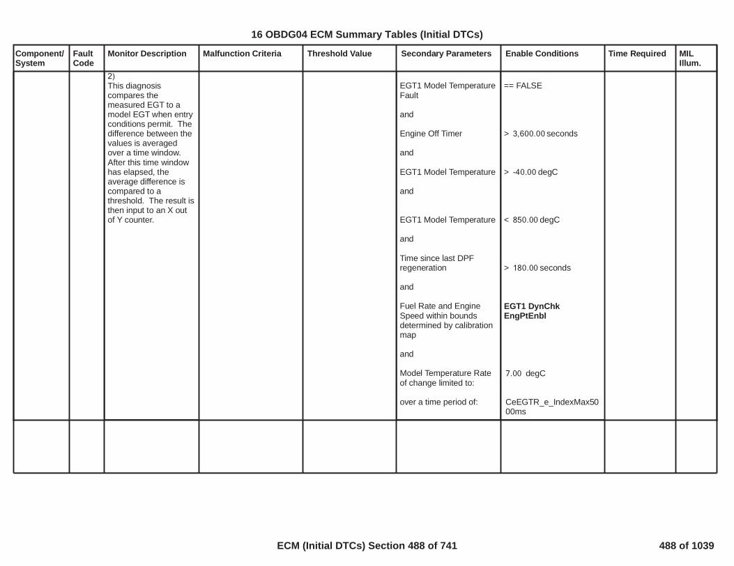
Component/System
FaultCode
Monitor Description Malfunction Criteria Threshold Value Secondary Parameters Enable Conditions Time Required MILIllum.
2)This diagnosiscompares themeasured EGT to amodel EGT when entryconditions permit. Thedifference between thevalues is averagedover a time window.After this time windowhas elapsed, theaverage difference iscompared to athreshold. The result isthen input to an X outof Y counter.
EGT1 Model TemperatureFault
and
Engine Off Timer
and
EGT1 Model Temperature
and
EGT1 Model Temperature
and
Time since last DPFregeneration
and
Fuel Rate and EngineSpeed within boundsdetermined by calibrationmap
and
Model Temperature Rateof change limited to:
over a time period of:
== FALSE
> seconds3,600.00
> degC-40.00
< degC850.00
> seconds180.00
EGT1 DynChkEngPtEnbl
degC7.00
CeEGTR_e_IndexMax5000ms
489
16 OBDG04 ECM Summary Tables (Initial DTCs)
ECM (Initial DTCs) Section 488 of 741 488 of 1039

Component/System
FaultCode
Monitor Description Malfunction Criteria Threshold Value Secondary Parameters Enable Conditions Time Required MILIllum.
|Reference temperature atsystem cold start up( ) – EGT2EGT_Avgtemperature|
See the Description Tabfor ReferenceTemperature,(T_AvrKeyOn) definition.
> [°C]20 Test enabled bycalibration(TRUE--> enableFALSE --> disable)
and with
Battery voltage
and with
No Active DTCs
and with
Reference temperaturecalculation done:
- key on
and with
- minimum engine-off time
and with
- Minimum number ofsensor available forcalculation
[Boolean]1
> [V]11.00
EGT_ExhGas2_CktTFTKO
==TRUE
> [sec]28,800.00
>=4
fail samples2out of
samples2
Function task:100ms
Exhaust GasTemperatureSensor NotPlausibleBank 1Sensor 2
P113C This diagnosis isfunction of twoseparate monitors.
1)
This diagnosis verify if,at key on, thetemperature value readby exhaust gastemperature 2 (EGT2)sensor is almost equalto the referencetemperature.
Reference temperatureis calculated asaverage value amongall the availablesystemtemperaturesensors(exhausttemperature sensors,coolant temperaturesensor, fueltemperature sensor,ambient temperaturesensor, intaketemperature sensor).The number of sensorused for the averagecalculation shall be atleast 4 but whichsensor to use iscalibratableand thesensor should not befaulted. The referencetemperature iscalculated at thesystem start up after acalibratable enginestop when all the
Type B,2 Trips
Difference between EGT2measured temperatureand modeled temperatureis greater than a thresholdfor a period of time.
(Measured EGT2 -Modeled EGT2) >100.00
OR
(Measured EGT2 -Modeled EGT2) <-100.00
Test Enabled bycalibration
and
Diag System Disable
and
Battery Voltage
and
1.00
== FALSE
> Volts11.00
fail6.00samples out of8.00
Each sample isseconds10.00
long
490
16 OBDG04 ECM Summary Tables (Initial DTCs)
ECM (Initial DTCs) Section 489 of 741 489 of 1039

Component/System
FaultCode
Monitor Description Malfunction Criteria Threshold Value Secondary Parameters Enable Conditions Time Required MILIllum.
temperature aresupposed to be similar.
2)
This diagnosiscompares themeasured EGT to amodel EGT when entryconditions permit. Thedifference between thevalues is averagedover a time window.After this time windowhas elapsed, theaverage difference iscompared to athreshold. The result isthen input to an X outof Y counter.
EGT2Model TemperatureFault
and
Engine Off Timer
and
EGT2Model Temperature
and
EGT2 Model Temperature
and
Time since last DPFregeneration
and
Fuel Rate and EngineSpeed within boundsdetermined by calibrationmap
and
Model Temperature Rateof change limited to:
over a time period of:
== FALSE
> seconds3,600.00
> degC-40.00
< degC850.00
> seconds180.00
EGT2 DynChkEngPtEnbl
degC7.00
CeEGTR_e_IndexMax5000ms
491
16 OBDG04 ECM Summary Tables (Initial DTCs)
ECM (Initial DTCs) Section 490 of 741 490 of 1039

Component/System
FaultCode
Monitor Description Malfunction Criteria Threshold Value Secondary Parameters Enable Conditions Time Required MILIllum.
|Reference temperature atsystem cold start up( ) – EGT3EGT_Avgtemperature|
See the Description Tabfor ReferenceTemperature,(T_AvrKeyOn) definition
> [°C]20 Test enabled bycalibration(TRUE--> enableFALSE --> disable)
and with
Battery voltage
and with
No Active DTCs
and with
Reference temperaturecalculation done:
- key on
and with
- minimum engine-off time
and with
- Number of sensoravailable for calculation
[Boolean]1
> [V]11.00
EGT_ExhGas3_CktTFTKO
==TRUE
> [sec]28,800.00
>=4
fail samples2out of samples2
Function task:100ms
Exhaust GasTemperatureSensor NotPlausibleBank 1Sensor 3
P113D This diagnosis isfunction of twoseparate monitors.
1)
This diagnosis verify if,at key on, thetemperature value readby exhaust gastemperature 3 (EGT3)sensor is almost equalto the referencetemperature.
Reference temperatureis calculated asaverage value amongall the availablesystemtemperaturesensors(exhausttemperature sensors,coolant temperaturesensor, fueltemperature sensor,ambient temperaturesensor, intaketemperature sensor).The number of sensorused for the averagecalculation shall be atleast 4 but whichsensor to use iscalibratableand thesensor should not befaulted. The referencetemperature iscalculated at thesystem start up after acalibratable enginestop when all the
Type B,2 Trips
Difference between EGT3measured temperatureand modeled temperatureis greater than a thresholdfor a period of time.
(Measured EGT3 -Modeled EGT3) >100.00OR
(Measured EGT3 -Modeled EGT3) <-100.00
Test Enabled bycalibration
and
Diag System Disable
and
Battery Voltage
and
1.00
== FALSE
> Volts11.00
fail6.00samples out of8.00
Each sample isseconds10.00
long
492
16 OBDG04 ECM Summary Tables (Initial DTCs)
ECM (Initial DTCs) Section 491 of 741 491 of 1039

Component/System
FaultCode
Monitor Description Malfunction Criteria Threshold Value Secondary Parameters Enable Conditions Time Required MILIllum.
temperature aresupposed to be similar.
2)
This diagnosiscompares themeasured EGT to amodel EGT when entryconditions permit. Thedifference between thevalues is averagedover a time window.After this time windowhas elapsed, theaverage difference iscompared to athreshold. The result isthen input to an X outof Y counter.
EGT3 Model TemperatureFault
and
Engine Off Timer
and
EGT3 Model Temperatureand
EGT3 Model Temperature
and
Time since last DPFregeneration
and
Fuel Rate and EngineSpeed within boundsdetermined by calibrationmap
and
Model Temperature Rateof change limited to:
over a time period of:
== FALSE
> seconds3,600.00
> degC-40.00
< degC850.00
> seconds180.00
EGT3 DynChkEngPtEnbl
degC7.00
CeEGTR_e_IndexMax5000ms
493
16 OBDG04 ECM Summary Tables (Initial DTCs)
ECM (Initial DTCs) Section 492 of 741 492 of 1039

Component/System
FaultCode
Monitor Description Malfunction Criteria Threshold Value Secondary Parameters Enable Conditions Time Required MILIllum.
|Reference temperature atsystem cold start up( ) – EGT4EGT_Avgtemperature|
See the Description Tabfor ReferenceTemperature,(T_AvrKeyOn) definition
> [°C]20 Test enabled bycalibration(TRUE--> enableFALSE --> disable)
and with
Battery voltage
and with
No Active DTCsand withReference temperaturecalculation done:
- key on
and with
- minimum engine-off timeand with
- Number of sensoravailable for calculation
[Boolean]1
> [V]11.00
EGT_ExhGas4_CktTFTKO
==TRUE
> [sec]28,800.00
>=4
fail samples2out of samples2
Function task:100ms
Exhaust GasTemperatureSensor 4 NotPlausible
P113E This diagnosis isfunction of twoseparate monitors.
1)
This diagnosis verify if,at key on, thetemperature value readby exhaust gastemperature 4 (EGT4)sensor is almost equalto the referencetemperature.
Reference temperatureis calculated asaverage value amongall the availablesystemtemperaturesensors(exhausttemperature sensors,coolant temperaturesensor, fueltemperature sensor,ambient temperaturesensor, intaketemperature sensor).The number of sensorused for the averagecalculation shall be atleast 4 but whichsensor to use iscalibratableand thesensor should not befaulted. The referencetemperature iscalculated at thesystem start up after acalibratable enginestop when all the
Type B,2 Trips
Difference between EGT4measured temperatureand modeled temperatureis greater than a thresholdfor a period of time.
(Measured EGT4 -Modeled EGT4) >100.00OR
(Measured EGT4 -Modeled EGT4) <-100.00
Test Enabled bycalibration
and
Diag System Disable
and
Battery Voltage
and
EGT4 Model TemperatureFault
1.00
== FALSE
> Volts11.00
== FALSE
fail6.00samples out of8.00
Each sample isseconds2.00
long
494
16 OBDG04 ECM Summary Tables (Initial DTCs)
ECM (Initial DTCs) Section 493 of 741 493 of 1039

Component/System
FaultCode
Monitor Description Malfunction Criteria Threshold Value Secondary Parameters Enable Conditions Time Required MILIllum.
temperature aresupposed to be similar.
2)
This diagnosiscompares themeasured EGT to amodel EGT when entryconditions permit. Thedifference between thevalues is averagedover a time window.After this time windowhas elapsed, theaverage difference iscompared to athreshold. The result isthen input to an X outof Y counter.
and
Engine Off Timer
and
EGT4 Model Temperature
and
EGT4 Model Temperature
and
Time since last DPFregeneration
and
Fuel Rate and EngineSpeed within boundsdetermined by calibrationmap
and
Model Temperature Rateof change limited to:
over a time period of:
> seconds3,600.00
> degC100.00
< degC1,000.00
> seconds300.00
EGT4 DynChkEngPtEnbl
degC1,000.00
CeEGTR_e_IndexMax5000ms
495
16 OBDG04 ECM Summary Tables (Initial DTCs)
ECM (Initial DTCs) Section 494 of 741 494 of 1039

Component/System
FaultCode
Monitor Description Malfunction Criteria Threshold Value Secondary Parameters Enable Conditions Time Required MILIllum.
|Reference temperature atsystem cold start up( ) – EGT5EGT_Avgtemperature|
See the Description Tabfor ReferenceTemperature,(T_AvrKeyOn) definition
> [°C]20 Test enabled bycalibration(TRUE--> enableFALSE --> disable)
and with
Battery voltage
and with
No Active DTCsand withReference temperaturecalculation done:
- key on
and with
- minimum engine-off timeand with
- Number of sensoravailablefor calculation
[Boolean]1
> [V]11.00
EGT_ExhGas5_CktTFTKO
==TRUE
> [sec]28,800.00
>=4
fail samples2out of samples2
Function task:100ms
Exhaust GasTemperatureSensor 5 NotPlausible
P113F This diagnosis isfunction of twoseparate monitors.
1)
This diagnosis verify if,at key on, thetemperature value readby exhaust gastemperature 5 (EGT5)sensor is almost equalto the referencetemperature.
Reference temperatureis calculated asaverage value amongall the availablesystemtemperaturesensors(exhausttemperature sensors,coolant temperaturesensor, fueltemperature sensor,ambient temperaturesensor, intaketemperature sensor).The number of sensorused for the averagecalculation shall be atleast 4 but whichsensor to use iscalibratableand thesensor should not befaulted. The referencetemperature iscalculated at thesystem start up after acalibratable enginestop when all the
Type B,2 Trips
Difference between EGT5measured temperatureand modeled temperatureis greater than a thresholdfor a period of time.
(Measured EGT5-Modeled EGT5) >100.00
OR
(Measured EGT5-Modeled EGT5) <-100.00
Test Enabled bycalibration
and
Diag System Disable
and
Battery Voltage
and
EGT5 Model TemperatureFault
1.00
== FALSE
> Volts11.00
== FALSE
fail6.00samples out of8.00
Each sample isseconds2.00
long
16 OBDG04 ECM Summary Tables (Initial DTCs)
ECM (Initial DTCs) Section 495 of 741 495 of 1039

Component/System
FaultCode
Monitor Description Malfunction Criteria Threshold Value Secondary Parameters Enable Conditions Time Required MILIllum.
temperature aresupposed to be similar.
2)
This diagnosiscompares themeasured EGT to amodel EGT when entryconditions permit. Thedifference between thevalues is averagedover a time window.After this time windowhas elapsed, theaverage difference iscompared to athreshold. The result isthen input to an X outof Y counter.
and
Engine Off Timer
and
EGT5 Model Temperature
and
EGT5 Model Temperature
and
Time since last DPFregeneration
and
Fuel Rate and EngineSpeed within boundsdetermined by calibrationmap
and
Model Temperature Rateof change limited to:over a time period of:
> seconds3,600.00
> degC100.00
< degC1,000.00
> seconds300.00
EGT5 DynChkEngPtEnbl
degC1,000.00
CeEGTR_e_IndexMax5000ms
16 OBDG04 ECM Summary Tables (Initial DTCs)
ECM (Initial DTCs) Section 496 of 741 496 of 1039

Component/System
FaultCode
Monitor Description Malfunction Criteria Threshold Value Secondary Parameters Enable Conditions Time Required MILIllum.
NOx Sensor1 O2ReferenceVoltageCircuit
P115E This diagnosis verifiesUpstream NOx gen3sensor O2 binaryreference voltage pinfor Open Load Circuit
Check if there is an opencircuit on NOx Sensor 1O2 Binary referencevoltage (P+ pin)
open circuit on P+ pin NOx sensor is Gen3.0
Powertrain relay voltage
NOx Sensor Bus relay iscommanded ON
CAN_LostComm_FltN_BusB_NOxSnsr_A
Sensor supply in range
Sensor dewpoint isreached
(Sensor heater rawresistance - sensor heatertarget resistance) / sensorheater target resistence
TRUE
> V11.00
TRUE
FALSE
> 10.8V
TRUE
< %0.03>- %0.03
Time counter:fails out of20samples40
Task=25ms
Type A,1 Trips
498
16 OBDG04 ECM Summary Tables (Initial DTCs)
ECM (Initial DTCs) Section 497 of 741 497 of 1039

Component/System
FaultCode
Monitor Description Malfunction Criteria Threshold Value Secondary Parameters Enable Conditions Time Required MILIllum.
NOx Sensor1 O2ReferenceVoltageCircuit LowVoltage
P115F This diagnosis verifiesUpstream NOx gen3sensor binary referencevoltage pin for Short toGround
Check if there is a shortcircuit to ground on NOxSensor 1O2 Binary referencevoltage (P+ pin)
groundshort on P+ pin NOx sensor is Gen3.0
Powertrain relay voltage
NOx Sensor Bus relay iscommanded ON
CAN_LostComm_FltN_BusB_NOxSnsr_A
Sensor supply in range
Sensor dewpoint isreached
(Sensor heater rawresistance - sensor heatertarget resistance) / sensorheater target resistence
TRUE
> V11.00
TRUE
FALSE
> 10.8V
TRUE
< %0.03>- %0.03
Time counter:fails out of20samples40
Task=25ms
Type B,2 Trips
499
16 OBDG04 ECM Summary Tables (Initial DTCs)
ECM (Initial DTCs) Section 498 of 741 498 of 1039

Component/System
FaultCode
Monitor Description Malfunction Criteria Threshold Value Secondary Parameters Enable Conditions Time Required MILIllum.
NOx Sensor1 O2ReferenceVoltageCircuit HighVoltage
P1160 This diagnosis verifiesUpstream NOx gen3sensor binary referencevoltage pin for Short toBattery
Check if there is a shortcircuit to power supply onNOx Sensor 1O2 Binary referencevoltage (P+ pin)
powershort on P+ pin NOx sensor is Gen3.0
Powertrain relay voltage
NOx Sensor Bus relay iscommanded ON
CAN_LostComm_FltN_BusB_NOxSnsr_A
Sensor supply in range
Sensor dewpoint isreached
(Sensor heater rawresistance - sensor heatertarget resistance) / sensorheater target resistence
TRUE
> V11.00
TRUE
FALSE
> 10.8V
TRUE
< %0.03>- %0.03
Time counter:fails out of20samples40
Task=25ms
Type B,2 Trips
500
16 OBDG04 ECM Summary Tables (Initial DTCs)
ECM (Initial DTCs) Section 499 of 741 499 of 1039

Component/System
FaultCode
Monitor Description Malfunction Criteria Threshold Value Secondary Parameters Enable Conditions Time Required MILIllum.
NOx Sensor1 O2 SignalCircuit
P116A This diagnosis verifiesUpstream NOx gen3sensor linear lambdacircuit pin for OpenLoad Circuit
Check if there is an opencircuit on NOx Sensor 1O2 Linear pin (P-)
open circuit on P- pin NOx sensor is Gen3.0
Powertrain relay voltage
NOx Sensor Bus relay iscommanded ON
CAN_LostComm_FltN_BusB_NOxSnsr_A
Sensor supply in range
Sensor dewpoint isreached
(Sensor heater rawresistance - sensor heatertarget resistance) / sensorheater target resistence
TRUE
> V11.00
TRUE
FALSE
> 10.8V
TRUE
< %0.03>- %0.03
Time counter:fails out of20samples40
Task=25ms
Type A,1 Trips
501
16 OBDG04 ECM Summary Tables (Initial DTCs)
ECM (Initial DTCs) Section 500 of 741 500 of 1039

Component/System
FaultCode
Monitor Description Malfunction Criteria Threshold Value Secondary Parameters Enable Conditions Time Required MILIllum.
NOx Sensor1 O2 SignalCircuit LowVoltage
P116B This diagnosis verifiesUpstream NOx gen3sensor linear lambdacircuit pin for Short toGround
Check if there is a shortcircuit to ground on NOxSensor 1O2 Linear pin (P-)
groundshort on P- pin NOx sensor is Gen3.0
Powertrain relay voltage
NOx Sensor Bus relay iscommanded ON
CAN_LostComm_FltN_BusB_NOxSnsr_A
Sensor supply in range
Sensor dewpoint isreached
(Sensor heater rawresistance - sensor heatertarget resistance) / sensorheater target resistence
TRUE
> V11.00
TRUE
FALSE
> 10.8V
TRUE
< %0.03>- %0.03
Time counter:fails out of20samples40
Task=25ms
Type B,2 Trips
502
16 OBDG04 ECM Summary Tables (Initial DTCs)
ECM (Initial DTCs) Section 501 of 741 501 of 1039

Component/System
FaultCode
Monitor Description Malfunction Criteria Threshold Value Secondary Parameters Enable Conditions Time Required MILIllum.
NOx Sensor1 O2 SignalCircuit HighVoltage
P116C This diagnosis verifiesUpstream NOx gen3sensor linear lambdacircuit pin for Short toBattery
Check if there is a shortcircuit to power supply onNOx Sensor 1O2 Linear pin (P-)
powershort on P- pin NOx sensor is Gen3.0
Powertrain relay voltage
NOx Sensor Bus relay iscommanded ON
CAN_LostComm_FltN_BusB_NOxSnsr_A
Sensor supply in range
Sensor dewpoint isreached
(Sensor heater rawresistance - sensor heatertarget resistance) / sensorheater target resistence
TRUE
> V11.00
TRUE
FALSE
> 10.8V
TRUE
< %0.03>- %0.03
Time counter:fails out of20samples40
Task=25ms
Type B,2 Trips
503
16 OBDG04 ECM Summary Tables (Initial DTCs)
ECM (Initial DTCs) Section 502 of 741 502 of 1039

Component/System
FaultCode
Monitor Description Malfunction Criteria Threshold Value Secondary Parameters Enable Conditions Time Required MILIllum.
NOx Sensor1 O2 PumpCurrentControlCircuit
P116D This diagnosis verifiesUpstream NOx gen3sensor O2 referencecircuit pin for OpenLoad Circuit
Check if there is an opencircuit on NOx Sensor 1O2 Reference pin(M1,auxiliary pumping current)
open circuit on M1 pin NOx sensor is Gen3.0
Powertrain relay voltage
NOx Sensor Bus relay iscommanded ON
CAN_LostComm_FltN_BusB_NOxSnsr_A
Sensor supply in range
Sensor dewpoint isreached
(Sensor heater rawresistance - sensor heatertarget resistance) / sensorheater target resistence
TRUE
> V11.00
TRUE
FALSE
> 10.8V
TRUE
< %0.03>- %0.03
Time counter:fails out of20samples40
Task=25ms
Type A,1 Trips
504
16 OBDG04 ECM Summary Tables (Initial DTCs)
ECM (Initial DTCs) Section 503 of 741 503 of 1039

Component/System
FaultCode
Monitor Description Malfunction Criteria Threshold Value Secondary Parameters Enable Conditions Time Required MILIllum.
NOx Sensor1 O2 PumpCurrentControlCircuit LowVoltage
P116E This diagnosis verifiesUpstream NOx gen3sensor O2 referencecircuit pin for Short toGround
Check if there is a shortcircuit to ground on NOxSensor 1 O2 Referencepin (M1, auxiliary pumpingcurrent)
groundshort on M1 pin NOx sensor is Gen3.0
Powertrain relay voltage
NOx Sensor Bus relay iscommanded ON
CAN_LostComm_FltN_BusB_NOxSnsr_A
Sensor supply in range
Sensor dewpoint isreached
(Sensor heater rawresistance - sensor heatertarget resistance) / sensorheater target resistence
TRUE
> V11.00
TRUE
FALSE
> 10.8V
TRUE
< %0.03>- %0.03
Time counter:fails out of20samples40
Task=25ms
Type B,2 Trips
505
16 OBDG04 ECM Summary Tables (Initial DTCs)
ECM (Initial DTCs) Section 504 of 741 504 of 1039

Component/System
FaultCode
Monitor Description Malfunction Criteria Threshold Value Secondary Parameters Enable Conditions Time Required MILIllum.
NOx Sensor1 O2 PumpCurrentControlCircuit HighVoltage
P116F This diagnosis verifiesUpstream NOx gen3sensor O2 referencecircuit pin for Short toBattery
Check if there is a shortcircuit to power supply onNOx Sensor 1 O2Referencepin (M1, auxiliary pumpingcurrent)
powershort on M1 pin NOx sensor is Gen3.0
Powertrain relay voltage
NOx Sensor Bus relay iscommanded ON
CAN_LostComm_FltN_BusB_NOxSnsr_A
Sensor supply in range
Sensor dewpoint isreached
(Sensor heater rawresistance - sensor heatertarget resistance) / sensorheater target resistence
TRUE
> V11.00
TRUE
FALSE
> 10.8V
TRUE
< %0.03>- %0.03
Time counter:fails out of20samples40
Task=25ms
Type B,2 Trips
506
16 OBDG04 ECM Summary Tables (Initial DTCs)
ECM (Initial DTCs) Section 505 of 741 505 of 1039

Component/System
FaultCode
Monitor Description Malfunction Criteria Threshold Value Secondary Parameters Enable Conditions Time Required MILIllum.
ParticulateMatterSensorTemperatureNotPlausible
P118B This diagnosis detectsa soot sensortemperature sensordamaged or a possibleparassitic resistance onthe wiring harnessbetween the sootsensor heater and thesoot sensor control unit
The absolute value of thedifference between thesoot sensor electrodetemperature at power-upand the average oftemperature sensors( )EGT_Avg
> °C20.00 Key is turned on
Ignition voltage in range
Soot Sensor bus relay iscommanded on
No electrical fault activeon Soot Sensor bus relay
No faults of CANcommunication loss withSoot Sensor
No Soot Sensor supplyundervoltage detected,i.e. supply sensor voltagefor a time
No electrical faultdetected on Soot Sensor
If enabled, the SootSensor temperaturecircuit low and highmonitoring reported a testpass
Ambient Air pressure
Ambient air pressuresensor not faulty
Time since Soot Sensorheating off when thesensor temperature has
NOT( )SBR_RlyFA
NOT(U02A3)
> V9.00> s0.10
NOT( )SOT_EleclFault
TPTKO on P1477TPTKO on P1478
> KPa1.00
AmbPresDfltdStatus =CeAAPR_e_AmbPresNotDfltd
> s28,800.00
No timedebounce
Type B,2 Trips
507
16 OBDG04 ECM Summary Tables (Initial DTCs)
ECM (Initial DTCs) Section 506 of 741 506 of 1039

Component/System
FaultCode
Monitor Description Malfunction Criteria Threshold Value Secondary Parameters Enable Conditions Time Required MILIllum.
been stored is
Timer since Soot Sensorheating off is not affectedby error on module offtimer
Calculation of thereference temperature atsystem start up is valid(this also include engineoff timer and enginemovement)
Diagnostic has not yetreported a pass or failure
NOT(ModuleOffTimeErr)
EGT_TempAvgVld
NOT (TPTKO OR TFTKO)on P118B
508
16 OBDG04 ECM Summary Tables (Initial DTCs)
ECM (Initial DTCs) Section 507 of 741 507 of 1039

Component/System
FaultCode
Monitor Description Malfunction Criteria Threshold Value Secondary Parameters Enable Conditions Time Required MILIllum.
NOx Sensor1 O2 LowReferenceCircuit
P1192 This diagnosis verifiesUpstream NOx gen3sensor Low ReferenceCircuit for Open LoadCircuit
Check if there is an opencircuit on NOx Sensor 1Low Reference pin (Ref)
open circuit on Ref pin NOx sensor is Gen3.0
Powertrain relay voltage
NOx Sensor Bus relay iscommanded ON
CAN_LostComm_FltN_BusB_NOxSnsr_A
Sensor supply in range
Sensor dewpoint isreached
(Sensor heater rawresistance - sensor heatertarget resistance) / sensorheater target resistence
TRUE
> V11.00
TRUE
FALSE
> 10.8V
TRUE
< %0.03>- %0.03
Time counter:fails out of20samples40
Task=25ms
Type A,1 Trips
509
16 OBDG04 ECM Summary Tables (Initial DTCs)
ECM (Initial DTCs) Section 508 of 741 508 of 1039

Component/System
FaultCode
Monitor Description Malfunction Criteria Threshold Value Secondary Parameters Enable Conditions Time Required MILIllum.
NOx Sensor1 O2 LowReferenceCircuit LowVoltage
P1193 This diagnosis verifiesUpstream NOx gen3sensor Low ReferenceCircuit for Short toGround
Check if there is an shortcircuit to ground on NOxSensor 1 Low Referencepin (Ref)
groundshort on Ref pin NOx sensor is Gen3.0
Powertrain relay voltage
NOx Sensor Bus relay iscommanded ON
CAN_LostComm_FltN_BusB_NOxSnsr_A
Sensor supply in range
Sensor dewpoint isreached
(Sensor heater rawresistance - sensor heatertarget resistance) / sensorheater target resistence
TRUE
> V11.00
TRUE
FALSE
> 10.8V
TRUE
< %0.03>- %0.03
Time counter:fails out of20samples40
Task=25ms
Type B,2 Trips
510
16 OBDG04 ECM Summary Tables (Initial DTCs)
ECM (Initial DTCs) Section 509 of 741 509 of 1039

Component/System
FaultCode
Monitor Description Malfunction Criteria Threshold Value Secondary Parameters Enable Conditions Time Required MILIllum.
NOx Sensor1 O2 LowReferenceCircuit HighVoltage
P1194 This diagnosis verifiesUpstream NOx gen3sensor Low ReferenceCircuit for Short toBattery
Check if there is an shortcircuit to power supply onNOx Sensor 1 LowReference pin (Ref)
powershort on Ref pin NOx sensor is Gen3.0
Powertrain relay voltage
NOx Sensor Bus relay iscommanded ON
CAN_LostComm_FltN_BusB_NOxSnsr_A
Sensor supply in range
Sensor dewpoint isreached
(Sensor heater rawresistance - sensor heatertarget resistance) / sensorheater target resistence
TRUE
> V11.00
TRUE
FALSE
> 10.8V
TRUE
< %0.03>- %0.03
Time counter:fails out of20samples40
Task=25ms
Type B,2 Trips
511
16 OBDG04 ECM Summary Tables (Initial DTCs)
ECM (Initial DTCs) Section 510 of 741 510 of 1039

Component/System
FaultCode
Monitor Description Malfunction Criteria Threshold Value Secondary Parameters Enable Conditions Time Required MILIllum.
NOx Sensor1 SignalCircuit
P119A This diagnosis verifiesUpstream NOx gen3sensor NOx Circuit forOpen Load Circuit
Check if there is an opencircuit on NOx Sensor 1NOx-relatedmeasurement pin (M2)
open circuit on M2 NOx sensor is Gen3.0
Powertrain relay voltage
NOx Sensor Bus relay iscommanded ON
CAN_LostComm_FltN_BusB_NOxSnsr_A
Sensor supply in range
Sensor dewpoint isreached
(Sensor heater rawresistance - sensor heatertarget resistance) / sensorheater target resistence
TRUE
> V11.00
TRUE
FALSE
> 10.8V
TRUE
< %0.03>- %0.03
Time counter:fails out of20samples40
Task=25ms
Type A,1 Trips
512
16 OBDG04 ECM Summary Tables (Initial DTCs)
ECM (Initial DTCs) Section 511 of 741 511 of 1039

Component/System
FaultCode
Monitor Description Malfunction Criteria Threshold Value Secondary Parameters Enable Conditions Time Required MILIllum.
NOx Sensor1 SignalCircuit LowVoltage
P119B This diagnosis verifiesUpstream NOx gen3sensor NOx Circuit forShort to Ground
Check if there is a shortcircuit to ground on NOxSensor 1NOx-relatedmeasurement pin (M2)
groundshort on M2 pin NOx sensor is Gen3.0
Powertrain relay voltage
NOx Sensor Bus relay iscommanded ON
CAN_LostComm_FltN_BusB_NOxSnsr_A
Sensor supply in range
Sensor dewpoint isreached
(Sensor heater rawresistance - sensor heatertarget resistance) / sensorheater target resistence
TRUE
> V11.00
TRUE
FALSE
> 10.8V
TRUE
< %0.03>- %0.03
Time counter:fails out of20samples40
Task=25ms
Type B,2 Trips
513
16 OBDG04 ECM Summary Tables (Initial DTCs)
ECM (Initial DTCs) Section 512 of 741 512 of 1039

Component/System
FaultCode
Monitor Description Malfunction Criteria Threshold Value Secondary Parameters Enable Conditions Time Required MILIllum.
NOx Sensor1 SignalCircuit HighVoltage
P119C This diagnosis verifiesUpstream NOx gen3sensor NOx Circuit forShort to Battery
Check if there is a shortcircuit to power supply onNOx Sensor 1NOx-relatedmeasurement pin (M2)
powershort on M2 pin NOx sensor is Gen3.0
Powertrain relay voltage
NOx Sensor Bus relay iscommanded ON
CAN_LostComm_FltN_BusB_NOxSnsr_A
Sensor supply in range
Sensor dewpoint isreached
(Sensor heater rawresistance - sensor heatertarget resistance) / sensorheater target resistence
TRUE
> V11.00
TRUE
FALSE
> 10.8V
TRUE
< %0.03>- %0.03
Time counter:fails out of20samples40
Task=25ms
Type B,2 Trips
514
16 OBDG04 ECM Summary Tables (Initial DTCs)
ECM (Initial DTCs) Section 513 of 741 513 of 1039

Component/System
FaultCode
Monitor Description Malfunction Criteria Threshold Value Secondary Parameters Enable Conditions Time Required MILIllum.
NOx Sensor2 SignalCircuit
P119D This diagnosis verifiesDownstream NOx gen3sensor NOx Circuit forOpen Load Circuit
Check if there is an opencircuit on NOx Sensor 2NOx-relatedmeasurement pin (M2)
open circuit on M2 pin NOx sensor is Gen3.0
Powertrain relay voltage
NOx Sensor Bus relay iscommanded ON
CAN_LostComm_FltN_BusB_NOxSnsr_B
Sensor supply in range
Sensor dewpoint isreached
(Sensor heater rawresistance - sensor heatertarget resistance) / sensorheater target resistence
TRUE
> V11.00
TRUE
FALSE
> 10.8V
TRUE
< %0.03>- %0.03
Time counter:fails out of20samples40
Task=25ms
Type A,1 Trips
515
16 OBDG04 ECM Summary Tables (Initial DTCs)
ECM (Initial DTCs) Section 514 of 741 514 of 1039

Component/System
FaultCode
Monitor Description Malfunction Criteria Threshold Value Secondary Parameters Enable Conditions Time Required MILIllum.
NOx Sensor2 SignalCircuit LowVoltage
P119E This diagnosis verifiesDownstream NOx gen3sensor NOx Circuit forShort to Ground
Check if there is a shortcircuit to ground on NOxSensor 2NOx-relatedmeasurement pin (M2)
groundshort on M2 pin NOx sensor is Gen3.0
Powertrain relay voltage
NOx Sensor Bus relay iscommanded ON
CAN_LostComm_FltN_BusB_NOxSnsr_B
Sensor supply in range
Sensor dewpoint isreached
(Sensor heater rawresistance - sensor heatertarget resistance) / sensorheater target resistence
TRUE
> V11.00
TRUE
FALSE
> 10.8V
TRUE
< %0.03>- %0.03
Time counter:fails out of20samples40
Task=25ms
Type B,2 Trips
516
16 OBDG04 ECM Summary Tables (Initial DTCs)
ECM (Initial DTCs) Section 515 of 741 515 of 1039

Component/System
FaultCode
Monitor Description Malfunction Criteria Threshold Value Secondary Parameters Enable Conditions Time Required MILIllum.
NOx Sensor2 SignalCircuit HighVoltage
P119F This diagnosis verifiesDownstream NOx gen3sensor NOx Circuit forShort to Battery
Check if there is a shortcircuit to power supply onNOx Sensor 2NOx-relatedmeasurement pin (M2)
powershort on M2 pin NOx sensor is Gen3.0
Powertrain relay voltage
NOx Sensor Bus relay iscommanded ON
CAN_LostComm_FltN_BusB_NOxSnsr_B
Sensor supply in range
Sensor dewpoint isreached
(Sensor heater rawresistance - sensor heatertarget resistance) / sensorheater target resistence
TRUE
> V11.00
TRUE
FALSE
> 10.8V
TRUE
< %0.03>- %0.03
Time counter:fails out of20samples40
Task=25ms
Type B,2 Trips
517
16 OBDG04 ECM Summary Tables (Initial DTCs)
ECM (Initial DTCs) Section 516 of 741 516 of 1039

Component/System
FaultCode
Monitor Description Malfunction Criteria Threshold Value Secondary Parameters Enable Conditions Time Required MILIllum.
O2 SensorPerformanceDuringDecelerationFuel Cut OffBank 1Sensor 2
P11B3 This DTC aims todetect a drift of Sensor2 O2 measured value(A) from Sensor 1 O2measured value (B)when the latter can beconsidered stableduring overruncondition.
EWMA filtered error (A -B) in overruncondition is out ofplausible range
> [%]1.38< [%]-2.83
Engine running
System voltage in range
Sensor is fully operative
Sensor 1 is fully operative
No pending or confirmedDTCs
DTC P2297 is running
Air mass flown sinceP2297
> [V]11.00
OXY_O2_NOx2_PresCmpNotRlb==FALSE
OXY_O2_NOx1_PresCmpNotRlb== FALSE
NOX_Snsr2_NotVld
(MAF_SensorFAAND
)MAF_SensorTFTKO
OXY_NOx1_O2_Flt
OXY_NOx2SignRngChkFlt
NOX_Snsr2_PresFlt
(see P2297 Fault code)
> [g]30.00
EWMA filtering:multiple tests pertrip are allowed.
Type B,2 Trips
518
16 OBDG04 ECM Summary Tables (Initial DTCs)
ECM (Initial DTCs) Section 517 of 741 517 of 1039

Component/System
FaultCode
Monitor Description Malfunction Criteria Threshold Value Secondary Parameters Enable Conditions Time Required MILIllum.
NOx Sensor2 O2ReferenceVoltageCircuit
P11BE This diagnosis verifiesDowstream NOx gen3sensor binary referencevoltage pin for OpenLoad Circuit
Check if there is an opencircuit on NOx Sensor 2O2 Binary referencevoltage (P+ pin)
open circuit on P+ pin NOx sensor is Gen3.0
Powertrain relay voltage
NOx Sensor Bus relay iscommanded ON
CAN_LostComm_FltN_BusB_NOxSnsr_B
Sensor supply in range
Sensor dewpoint isreached
(Sensor heater rawresistance - sensor heatertarget resistance) / sensorheater target resistence
TRUE
> V11.00
TRUE
FALSE
> 10.8V
TRUE
< %0.03>- %0.03
Time counter:fails out of20samples40
Task=25ms
Type A,1 Trips
519
16 OBDG04 ECM Summary Tables (Initial DTCs)
ECM (Initial DTCs) Section 518 of 741 518 of 1039

Component/System
FaultCode
Monitor Description Malfunction Criteria Threshold Value Secondary Parameters Enable Conditions Time Required MILIllum.
NOx Sensor2 O2ReferenceVoltageCircuit LowVoltage
P11BF This diagnosis verifiesDownstream NOx gen3sensor binary referencevoltage pin for Short toGround
Check if there is a shortcircuit to ground on NOxSensor 2O2 Binary referencevoltage (P+ pin)
groundshort on P+ pin NOx sensor is Gen3.0
Powertrain relay voltage
NOx Sensor Bus relay iscommanded ON
CAN_LostComm_FltN_BusB_NOxSnsr_B
Sensor supply in range
Sensor dewpoint isreached
(Sensor heater rawresistance - sensor heatertarget resistance) / sensorheater target resistence
TRUE
> V11.00
TRUE
FALSE
> 10.8V
TRUE
< %0.03>- %0.03
Time counter:fails out of20samples40
Task=25ms
Type B,2 Trips
520
16 OBDG04 ECM Summary Tables (Initial DTCs)
ECM (Initial DTCs) Section 519 of 741 519 of 1039

Component/System
FaultCode
Monitor Description Malfunction Criteria Threshold Value Secondary Parameters Enable Conditions Time Required MILIllum.
NOx Sensor2 O2ReferenceVoltageCircuit HighVoltage
P11C0 This diagnosis verifiesDownstream NOx gen3sensor binary referencevoltage pin for Short toBattery
Check if there is an shortcircuit to power supply onNOx Sensor 2O2 Binary referencevoltage (P+ pin)
powershort on P+ pin NOx sensor is Gen3.0
Powertrain relay voltage
NOx Sensor Bus relay iscommanded ON
CAN_LostComm_FltN_BusB_NOxSnsr_B
Sensor supply in range
Sensor dewpoint isreached
(Sensor heater rawresistance - sensor heatertarget resistance) / sensorheater target resistence
TRUE
> V11.00
TRUE
FALSE
> 10.8V
TRUE
< %0.03>- %0.03
Time counter:fails out of20samples40
Task=25ms
Type B,2 Trips
521
16 OBDG04 ECM Summary Tables (Initial DTCs)
ECM (Initial DTCs) Section 520 of 741 520 of 1039

Component/System
FaultCode
Monitor Description Malfunction Criteria Threshold Value Secondary Parameters Enable Conditions Time Required MILIllum.
NOx Sensor1 HeaterGroundCircuit
P11C5 This diagnosis verifiesUpstream NOx gen3sensor heater groundcircuit open
Check if there is an opencircuit on NOx Sensor 1heater reference pin (H-)
open circuit on H- pin NOx sensor is Gen3.0
Powertrain relay voltage
NOx Sensor Bus relay iscommanded ON
CAN_LostComm_FltN_BusB_NOxSnsr_A
Sensor supply in range
TRUE
> V11.00
TRUE
FALSE
> 10.8V
Time counter:fails out of20samples40
Task=25ms
Type A,1 Trips
522
16 OBDG04 ECM Summary Tables (Initial DTCs)
ECM (Initial DTCs) Section 521 of 741 521 of 1039

Component/System
FaultCode
Monitor Description Malfunction Criteria Threshold Value Secondary Parameters Enable Conditions Time Required MILIllum.
NOx Sensor1 HeaterGroundCircuit HighVoltage
P11C6 This diagnosis verifiesUpstream NOx gen3sensor heater groundcircuit Short to Battery
Check if there is shortcircuit to power supply onNOx Sensor 1 heaterreference pin (H-)
powershort on H- NOx sensor is Gen3.0
Powertrain relay voltage
NOx Sensor Bus relay iscommanded ON
CAN_LostComm_FltN_BusB_NOxSnsr_A
Sensor supply in range
Sensor dewpoint isreached
(Sensor heater rawresistance - sensor heatertarget resistance) / sensorheater target resistence
TRUE
> V11.00
TRUE
FALSE
> 10.8V
TRUE
< %0.03>- %0.03
Time counter:fails out of20samples40
Task=25ms
Type B,2 Trips
523
16 OBDG04 ECM Summary Tables (Initial DTCs)
ECM (Initial DTCs) Section 522 of 741 522 of 1039

Component/System
FaultCode
Monitor Description Malfunction Criteria Threshold Value Secondary Parameters Enable Conditions Time Required MILIllum.
NOx Sensor2 HeaterGroundCircuit
P11C7 This diagnosis verifiesDownstream NOx gen3sensor heater groundcircuit open
Check if there is an opencircuit on NOx Sensor 2heater reference pin(H-)
open circuit on H- pin NOx sensor is Gen3.0
Powertrain relay voltage
NOx Sensor Bus relay iscommanded ON
CAN_LostComm_FltN_BusB_NOxSnsr_B
Sensor supply in range
TRUE
> V11.00
TRUE
FALSE
> 10.8V
Time counter:fails out of20samples40
Task=25ms
Type A,1 Trips
524
16 OBDG04 ECM Summary Tables (Initial DTCs)
ECM (Initial DTCs) Section 523 of 741 523 of 1039

Component/System
FaultCode
Monitor Description Malfunction Criteria Threshold Value Secondary Parameters Enable Conditions Time Required MILIllum.
NOx Sensor2 HeaterGroundCircuit HighVoltage
P11C8 This diagnosis verifiesDowmstream NOxgen3 sensor heaterground circuit Short toBattery
Check if there is a shortcircuit to power on NOxSensor 2 heater referencepin (H-)
powershort on H- pin NOx sensor is Gen3.0
Powertrain relay voltage
NOx Sensor Bus relay iscommanded ON
CAN_LostComm_FltN_BusB_NOxSnsr_B
Sensor supply in range
Sensor dewpoint isreached
(Sensor heater rawresistance - sensor heatertarget resistance) / sensorheater target resistence
TRUE
> V11.00
TRUE
FALSE
> 10.8V
TRUE
< %0.03>- %0.03
Time counter:fails out of20samples40
Task=25ms
Type B,2 Trips
525
16 OBDG04 ECM Summary Tables (Initial DTCs)
ECM (Initial DTCs) Section 524 of 741 524 of 1039

Component/System
FaultCode
Monitor Description Malfunction Criteria Threshold Value Secondary Parameters Enable Conditions Time Required MILIllum.
NOx SensorPerformance- Signal LowBank 1Sensor 1
P11CC This diagnosis verifiesthe plausibility ofUpstream NOx sensorsignal
Check if(Upstream NOx Sensorsignal - NOx Model)/NOxModel with EWMA filteris above or below twocalibratable thresholds
< %-50OR> %38.00
Engine is running
Powertrain relay voltage
No failure on any NOxmodel inputs
Injection small quantityadjustment (SQA)learning is not active
No failure on NOx1 CANcommunication
No electrical failure onNOx1 sensor
No out of range low failureon NOx1 sensor
No out of range highfailure on NOx1 sensor
No current control failureon NOx1 sensor
No failure on outside airtemperature sensor
No failure on ambient airtemperature sensor
no falut on upstreamcatalyst exhaust pressuremodel inputs
No failure on enginecoolant temperature
TRUE
> V11.00
EXM_NOxMdl_ExhMnfdNotVld==FALSE
FAD_SQA_LrnET_Enbl==FALSE
CAN_LostComm_FltN_BusB_NOxSnsr_A==FALSE
NOX_Snsr1_ElecFA==FALSE
NOX_NOx1_OutOfRngLoFlt==FALSE
NOX_NOx1_OutOfRngHiFlt==FALSE
NOX_NOx1_StBitChkFlt==FALSE
OAT_PtEstFiltFA==FALSE
AmbPresDfltdStatus==FALSE
EGP_PresCatUpFlt==FALSE
ECT_Sensor_FA
Test per trip: 1
If Fast InitialResponseEWMA is activethen test per0trip are allowed
If Fast InitialResponseEWMA is activethen test per0trip are allowed
Type B,2 Trips
526
16 OBDG04 ECM Summary Tables (Initial DTCs)
ECM (Initial DTCs) Section 525 of 741 525 of 1039

Component/System
FaultCode
Monitor Description Malfunction Criteria Threshold Value Secondary Parameters Enable Conditions Time Required MILIllum.
sensor
No failure on injectors
No failure on highpressure fuel rail system
No failure on intakemanifold absolutepressure sensor
Modeled Upstream NOxconcentration
Steady state detection:a) Modeled UpstreamNOx concentration step at100 ms.b) condition a) is fulfilledfor time
Ambient air pressure
Outside air temperature
Combustion modedependent enabling flag
Intake manifold absolutepressure
Injection fuel quantityrequested
==FALSE
FUL_GenericInjSysFlt==FALSE
FHP_InjLeakage==FALSE
==FALSEMAP_SensorFA
> ppm100
< ppm5
> sec5.00
> kPa70< kPa120
> °C-7< °C45
NOX_S1_PlausChkEnblCmbMode
< kPA250
For normal combustionmode:> mm^317.00< mm^350.00
For other combustionmodes:> mm^315
527
16 OBDG04 ECM Summary Tables (Initial DTCs)
ECM (Initial DTCs) Section 526 of 741 526 of 1039

Component/System
FaultCode
Monitor Description Malfunction Criteria Threshold Value Secondary Parameters Enable Conditions Time Required MILIllum.
Engine speed
Engine coolanttemperature
Sensor dewpoint isreached
Diagnostic test resultsduring EWMA FIR mode
< mm^330
For normal combustionmode:> rpm1,500< rpm2,000
For other combustionmodes:> rpm0< rpm0
> °C70< °C120
TRUE
< 0
528
16 OBDG04 ECM Summary Tables (Initial DTCs)
ECM (Initial DTCs) Section 527 of 741 527 of 1039

Component/System
FaultCode
Monitor Description Malfunction Criteria Threshold Value Secondary Parameters Enable Conditions Time Required MILIllum.
NOx Sensor2 O2 SignalCircuit
P11D0 This diagnosis verifiesDowstream NOx gen3sensor O2 referencecircuit pin for OpenLoad Circuit
Check if there is an opencircuit on NOx Sensor 2O2 Linear pin (P-)
open circuit on P- NOx sensor is Gen3.0
Powertrain relay voltage
NOx Sensor Bus relay iscommanded ON
CAN_LostComm_FltN_BusB_NOxSnsr_B
Sensor supply in range
Sensor dewpoint isreached
(Sensor heater rawresistance - sensor heatertarget resistance) / sensorheater target resistence
TRUE
> V11.00
TRUE
FALSE
> 10.8V
TRUE
< %0.03>- %0.03
Time counter:fails out of20samples40
Task=25ms
Type A,1 Trips
529
16 OBDG04 ECM Summary Tables (Initial DTCs)
ECM (Initial DTCs) Section 528 of 741 528 of 1039

Component/System
FaultCode
Monitor Description Malfunction Criteria Threshold Value Secondary Parameters Enable Conditions Time Required MILIllum.
NOx Sensor2 O2 SignalCircuit LowVoltage
P11D1 This diagnosis verifiesDownstream NOx gen3sensor linear lambdacircuit pin for Short toGround
Check if there is a shortcircuit to ground on NOxSensor 2 O2 Linear pin(P-)
groundshort on P- pin NOx sensor is Gen3.0
Powertrain relay voltage
NOx Sensor Bus relay iscommanded ON
CAN_LostComm_FltN_BusB_NOxSnsr_B
Sensor supply in range
Sensor dewpoint isreached
(Sensor heater rawresistance - sensor heatertarget resistance) / sensorheater target resistence
TRUE
> V11.00
TRUE
FALSE
> 10.8V
TRUE
< %0.03>- %0.03
Time counter:fails out of20samples40
Task=25ms
Type B,2 Trips
530
16 OBDG04 ECM Summary Tables (Initial DTCs)
ECM (Initial DTCs) Section 529 of 741 529 of 1039

Component/System
FaultCode
Monitor Description Malfunction Criteria Threshold Value Secondary Parameters Enable Conditions Time Required MILIllum.
NOx Sensor2 O2 SignalCircuit HighVoltage
P11D2 This diagnosis verifiesDownstream NOx gen3sensor linear lambdacircuit pin for Short toBattery
Check if there is a shortcircuit to power supply onNOx Sensor 2 O2 Linearpin (P-)
powershort on P- pin NOx sensor is Gen3.0
Powertrain relay voltage
NOx Sensor Bus relay iscommanded ON
CAN_LostComm_FltN_BusB_NOxSnsr_B
Sensor supply in range
Sensor dewpoint isreached
(Sensor heater rawresistance - sensor heatertarget resistance) / sensorheater target resistence
TRUE
> V11.00
TRUE
FALSE
> 10.8V
TRUE
< %0.03>- %0.03
Time counter:fails out of20samples40
Task=25ms
Type B,2 Trips
531
16 OBDG04 ECM Summary Tables (Initial DTCs)
ECM (Initial DTCs) Section 530 of 741 530 of 1039

Component/System
FaultCode
Monitor Description Malfunction Criteria Threshold Value Secondary Parameters Enable Conditions Time Required MILIllum.
NOx Sensor2 O2 PumpCurrentControlCircuit
P11D8 This diagnosis verifiesDownstream NOx gen3sensor O2 referencecircuit pin for OpenLoad Circuit
Check if there is an opencircuit on NOx Sensor 2O2 Reference pin (M1,auxiliary pumping current)
open circuit on M1 pin NOx sensor is Gen3.0
Powertrain relay voltage
NOx Sensor Bus relay iscommanded ON
CAN_LostComm_FltN_BusB_NOxSnsr_B
Sensor supply in range
Sensor dewpoint isreached
(Sensor heater rawresistance - sensor heatertarget resistance) / sensorheater target resistence
TRUE
> V11.00
TRUE
FALSE
> 10.8V
TRUE
< %0.03>- %0.03
Time counter:fails out of20samples40
Task=25ms
Type A,1 Trips
532
16 OBDG04 ECM Summary Tables (Initial DTCs)
ECM (Initial DTCs) Section 531 of 741 531 of 1039

Component/System
FaultCode
Monitor Description Malfunction Criteria Threshold Value Secondary Parameters Enable Conditions Time Required MILIllum.
NOx Sensor2 O2 PumpCurrentControlCircuit LowVoltage
P11D9 This diagnosis verifiesDownstream NOx gen3sensor O2 referencecircuit pin for Short toGround
Check if there is a shortcircuit to ground on NOxSensor 2O2 Reference pin (M1,auxiliary pumping current)
groundshort on M1 pin NOx sensor is Gen3.0
Powertrain relay voltage
NOx Sensor Bus relay iscommanded ON
CAN_LostComm_FltN_BusB_NOxSnsr_B
Sensor supply in range
Sensor dewpoint isreached
(Sensor heater rawresistance - sensor heatertarget resistance) / sensorheater target resistence
TRUE
> V11.00
TRUE
FALSE
> 10.8V
TRUE
< %0.03>- %0.03
Time counter:fails out of20samples40
Task=25ms
Type B,2 Trips
533
16 OBDG04 ECM Summary Tables (Initial DTCs)
ECM (Initial DTCs) Section 532 of 741 532 of 1039

Component/System
FaultCode
Monitor Description Malfunction Criteria Threshold Value Secondary Parameters Enable Conditions Time Required MILIllum.
NOx Sensor2 O2 PumpCurrentControlCircuit HighVoltage
P11DA This diagnosis verifiesDownstream NOx gen3sensor O2 referencecircuit pin for Short toBattery
Check if there is a shortcircuit to power supply onNOx Sensor 2O2 Reference pin (M1,auxiliary pumping current)
powershort on M1 pin NOx sensor is Gen3.0
Powertrain relay voltage
NOx Sensor Bus relay iscommanded ON
CAN_LostComm_FltN_BusB_NOxSnsr_B
Sensor supply in range
Sensor dewpoint isreached
(Sensor heater rawresistance - sensor heatertarget resistance) / sensorheater target resistence
TRUE
> V11.00
TRUE
FALSE
> 10.8V
TRUE
< %0.03>- %0.03
Time counter:fails out of20samples40
Task=25ms
Type B,2 Trips
534
16 OBDG04 ECM Summary Tables (Initial DTCs)
ECM (Initial DTCs) Section 533 of 741 533 of 1039

Component/System
FaultCode
Monitor Description Malfunction Criteria Threshold Value Secondary Parameters Enable Conditions Time Required MILIllum.
NOx SensorCurrentRange/Performance- Bank 1Sensor 1
P11DB This diagnosis verifiesthat Upstream NOxsensor embeddedcurrent control circuitstatus is healthy
Check if the NOx1 sensorembedded stability criteriaof Nox/Lambda currentcontrol circuit are violated
NOx stability flag:(OFF_Time/TOTAL_time)
Lambda stability flag:(OFF_Time/TOTAL_time)
Note:TOTAL_time= ON_time+OFF_Time
Stability flag for NOxsignal is set to OFF ifone of the followingcondition is not fulfilled:a) V2 within an intervalof 40mV around its setpointb) Delta Ip2 <426nA/10msecc) Ip1 within theinterval of -40 uA... 19uAd) Delta Ip1 < 2.4 uAaorund its set point
Stability flag for NOxsignal is set to OFF ifone of the followingcondition is not fulfilled:a) Ip1 within theinterval of -40uA...19uAb) Delta Ip0 < 300uA /10 msecc) Delta Ip1 z 2.4 uAaround its set point
> %1
> %1
Powertrain relay voltage
NOx Sensor Bus relay iscommanded ON
CAN_LostComm_FltN_BusB_NOxSnsr_A
Sensor supply in range
Sensor dewpoint isreached
Sensor heater is in range:a) (Sensor heater rawresistance - sensor heatertarget resistance) / sensorheater target resistenceb) condition a) is fulfilledfor time
Engine is running
No electrical failure onNOx1 sensor
Combustion modedependent enabling flag
> V11.00
TRUE
FALSE
> 10.8V
TRUE
< %0.03>- %0.03
> sec10.00
TRUE
NOX_Snsr1_ElecFA==FALSE
NOX_S1_StBitChkEnblCmbMode
NOx stability flagtime counter:
fails out of1samples1
Lambda stabilityflag time counter:
fails out of1 1samples
Task=25ms
Type B,2 Trips
535
16 OBDG04 ECM Summary Tables (Initial DTCs)
ECM (Initial DTCs) Section 534 of 741 534 of 1039

Component/System
FaultCode
Monitor Description Malfunction Criteria Threshold Value Secondary Parameters Enable Conditions Time Required MILIllum.
NOx SensorCurrentRange/Performance- Bank 1Sensor 2
P11DC This diagnosis verifiesthat Downstream NOxsensor embeddedcurrent control circuitstatus is healthy
Check if the NOx2 sensorembedded stability criteriaof Nox/Lambda currentcontrol circuit are violated
NOx stability flag:(OFF_Time/TOTAL_time)
Lambda stability flag:(OFF_Time/TOTAL_time)
Note:
Stability flag for NOxsignal is set to OFF ifone of the followingcondition is not fulfilled:
a) V2 within an intervalof 40mV around its setpointb) Delta Ip2 <426nA/10msecc) Ip1 within theinterval of -40 uA... 19uAd) Delta Ip1 < 2.4 uAaorund its set point
Stability flag for NOxsignal is set to OFF ifone of the followingcondition is not fulfilled:
a) Ip1 within theinterval of -40uA...19uAb) Delta Ip0 < 300uA /10 msecc) Delta Ip1 z 2.4 uAaround its set point
> %1
> %1
Powertrain relay voltage
NOx Sensor Bus relay iscommanded ON
CAN_LostComm_FltN_BusB_NOxSnsr_B
Sensor supply in range
Sensor dewpoint isreached
Sensor heater is in range:a) (Sensor heater rawresistance - sensor heatertarget resistance) / sensorheater target resistence
b) condition a) is fulfilledfor time
Engine is running
No electrical failure onNOx2 sensor
Combustion modedependent enabling flag
> V11.00
TRUE
FALSE
> 10.8V
TRUE
< %0.03>- %0.03
> sec10.00
TRUE
NOX_Snsr2_ElecFA==FALSE
NOX_S2_StBitChkEnblCmbMode
NOx stability flagtime counter: 1fails out of 1samples
Lambda stabilityflag time counter:
fails out of1samples1
Task=25ms
Type B,2 Trips
536
16 OBDG04 ECM Summary Tables (Initial DTCs)
ECM (Initial DTCs) Section 535 of 741 535 of 1039

Component/System
FaultCode
Monitor Description Malfunction Criteria Threshold Value Secondary Parameters Enable Conditions Time Required MILIllum.
TOTAL_time= ON_time+OFF_Time
537
16 OBDG04 ECM Summary Tables (Initial DTCs)
ECM (Initial DTCs) Section 536 of 741 536 of 1039

Component/System
FaultCode
Monitor Description Malfunction Criteria Threshold Value Secondary Parameters Enable Conditions Time Required MILIllum.
NOx Sensor2 O2 LowReferenceCircuit
P11FC This diagnosis verifiesDowstream NOx gen3sensor Low ReferenceCircuit for Open LoadCircuit
Check if there is an opencircuit on NOx Sensor 2Low Reference pin (Ref)
open circuit on Ref pin NOx sensor is Gen3.0
Powertrain relay voltage
NOx Sensor Bus relay iscommanded ON
CAN_LostComm_FltN_BusB_NOxSnsr_B
Sensor supply in range
Sensor dewpoint isreached
(Sensor heater rawresistance - sensor heatertarget resistance) / sensorheater target resistence
TRUE
> V11.00
TRUE
FALSE
> 10.8V
TRUE
< %0.03>- %0.03
Time counter:fails out of20samples40
Task=25ms
Type A,1 Trips
538
16 OBDG04 ECM Summary Tables (Initial DTCs)
ECM (Initial DTCs) Section 537 of 741 537 of 1039

Component/System
FaultCode
Monitor Description Malfunction Criteria Threshold Value Secondary Parameters Enable Conditions Time Required MILIllum.
NOx Sensor2 O2 LowReferenceCircuit LowVoltage
P11FD This diagnosis verifiesDownstream NOx gen3sensor Low ReferenceCircuit for Short toGround
Check if there is a shortcircuit to ground on NOxSensor 2 Low Referencepin (Ref)
groundshort on Ref pin NOx sensor is Gen3.0
Powertrain relay voltage
NOx Sensor Bus relay iscommanded ON
CAN_LostComm_FltN_BusB_NOxSnsr_B
Sensor supply in range
Sensor dewpoint isreached
(Sensor heater rawresistance - sensor heatertarget resistance) / sensorheater target resistence
TRUE
> V11.00
TRUE
FALSE
> 10.8V
TRUE
< %0.03>- %0.03
Time counter:fails out of20samples40
Task=25ms
Type B,2 Trips
539
16 OBDG04 ECM Summary Tables (Initial DTCs)
ECM (Initial DTCs) Section 538 of 741 538 of 1039

Component/System
FaultCode
Monitor Description Malfunction Criteria Threshold Value Secondary Parameters Enable Conditions Time Required MILIllum.
NOx Sensor2 O2 LowReferenceCircuit HighVoltage
P11FE This diagnosis verifiesDownstream NOx gen3sensor Low ReferenceCircuit for Short toBattery
Check if there is a shortcircuit to power supply onNOx Sensor 2 LowReference pin (Ref)
powershort on Ref pin NOx sensor is Gen3.0
Powertrain relay voltage
NOx Sensor Bus relay iscommanded ON
CAN_LostComm_FltN_BusB_NOxSnsr_B
Sensor supply in range
Sensor dewpoint isreached
(Sensor heater rawresistance - sensor heatertarget resistance) / sensorheater target resistence
TRUE
> V11.00
TRUE
FALSE
> 10.8V
TRUE
< %0.03>- %0.03
Time counter:fails out of20samples40
Task=25ms
Type B,2 Trips
540
16 OBDG04 ECM Summary Tables (Initial DTCs)
ECM (Initial DTCs) Section 539 of 741 539 of 1039

Component/System
FaultCode
Monitor Description Malfunction Criteria Threshold Value Secondary Parameters Enable Conditions Time Required MILIllum.
Diesel IntakeAir FlowControlPositiveVoltageCircuit
P122B This monitor checks ifthe Throttle DC-Motoris correctly supplied
Error interface providedby HWIO
Error interfaceprovided by HWIO ==TRUE
Test enabled bycalibration(TRUE --> enable
System out of thecranking phase
PT relay supply voltage inrange
Error interface providedby HWIO !=INDETERMINATE
==TRUE1.00
> [V]11.00
96.00fail counts out of120.00sample counts
Function task:12.5 ms
Type B,2 Trips
541
16 OBDG04 ECM Summary Tables (Initial DTCs)
ECM (Initial DTCs) Section 540 of 741 540 of 1039

Component/System
FaultCode
Monitor Description Malfunction Criteria Threshold Value Secondary Parameters Enable Conditions Time Required MILIllum.
Diesel IntakeAir FlowControlCircuitShorted
P122C This monitor checks ifthe Throttle commandsare shorted one other
Error interface providedby HWIO
Error interfaceprovided by HWIO ==TRUE
Test enabled bycalibration
System out of thecranking phase
PT relay supply voltage inrange
Error interface providedby HWIO !=INDETERMINATE
==TRUE1.00
> [V]11.00
96.00fail counts out of120.00sample counts
Function task:12.5 ms
Type B,2 Trips
542
16 OBDG04 ECM Summary Tables (Initial DTCs)
ECM (Initial DTCs) Section 541 of 741 541 of 1039

Component/System
FaultCode
Monitor Description Malfunction Criteria Threshold Value Secondary Parameters Enable Conditions Time Required MILIllum.
analog position rawvoltage when the valve isin fully closed position <low threshold
OR
analog position rawvoltage when the valve isin fully closed position >high threshold
< %5V81.75
OR
> %5V95.75
Test enabled bycalibration
Key signal is off
Learning procedure at keyoff in fully closed positionhas been successfullycompleted (no faultspresent on Throttleposition sensor, Throttlevalve, Throttle positiondeviation)
End Of Trip event haselapsed
==TRUE1.00
==TPS_PstnShtOffReqFALSE
1.00fail counts out of1.00sample counts
Function task:at key off
Diesel IntakeAir FlowPositionSensorExceededLearningLimit
P122D This monitor checks ifthe Throttle positionanalog or SENT sensorhas an offset withrespect to the nominalposition where thevalve does the learningprocedure (fully closed)
Type B,2 Trips
SENT position rawvoltage when the valve isin fully closed position <low threshold
OR
SENT position rawvoltage when the valve isin fully closed position >highthreshold
< %5V81.75
OR
> %5V95.75
Test enabled bycalibration
Key signal is off
Learning procedure at keyoff in fully closed positionhas been successfullycompleted (no faultspresent on Throttleposition sensor, Throttlevalve, Throttle positiondeviation)
End Of Trip event haselapsed
==TRUE1.00
==TPS_PstnShtOffReqFALSE
1.00fail counts out of1.00sample counts
Function task:at key off
543
16 OBDG04 ECM Summary Tables (Initial DTCs)
ECM (Initial DTCs) Section 542 of 741 542 of 1039

Component/System
FaultCode
Monitor Description Malfunction Criteria Threshold Value Secondary Parameters Enable Conditions Time Required MILIllum.
Injector 1PositiveVoltageControlCircuitShorted toControlCircuit
P1248 This DTC detects ashorted load on Injector1
Voltage high across lowside and High side driversduring on state indicateslow side shorted to highside
the time to reach the 2A threshold of theinjector current isshorter than 2 us
Test enabled bycalibration;
andBattery voltage
andKey ON
andEngine is not cranking
andEngine Running
andFUL_OutEnblCyl_CiEPSR_CylinderA
== [Boolean]1
> [V]11.00
-
-
>= [s]1.00
== 0 [Boolean]
failures out of5samples10
100 ms/sampleContinuous
Type A,1 Trips
544
16 OBDG04 ECM Summary Tables (Initial DTCs)
ECM (Initial DTCs) Section 543 of 741 543 of 1039

Component/System
FaultCode
Monitor Description Malfunction Criteria Threshold Value Secondary Parameters Enable Conditions Time Required MILIllum.
Injector 2PositiveVoltageControlCircuitShorted toControlCircuit
P1249 This DTC detects ashorted load on Injector2
Voltage high across lowside and High side driversduring on state indicateslow side shorted to highside
the time to reach the 2A threshold of theinjector current isshorter than 2 us
Test enabled bycalibration;
andBattery voltage
andKey ON
andEngine is not cranking
andEngine Running
andFUL_OutEnblCyl_CiEPSR_CylinderD
== [Boolean]1
> [V]11.00
-
-
>= [s]1.00
== 0 [Boolean]
failures out of5samples10
100 ms/sampleContinuous
Type A,1 Trips
545
16 OBDG04 ECM Summary Tables (Initial DTCs)
ECM (Initial DTCs) Section 544 of 741 544 of 1039

Component/System
FaultCode
Monitor Description Malfunction Criteria Threshold Value Secondary Parameters Enable Conditions Time Required MILIllum.
Injector 3PositiveVoltageControlCircuitShorted toControlCircuit
P124A This DTC detects ashorted load on Injector3
Voltage high across lowside and High side driversduring on state indicateslow side shorted to highside
the time to reach the 2A threshold of theinjector current isshorter than 2 us
Test enabled bycalibration;
andBattery voltage
andKey ON
andEngine is not cranking
andEngine Running
andFUL_OutEnblCyl_CiEPSR_CylinderB
== [Boolean]1
> [V]11.00
-
-
>= [s]1.00
== 0 [Boolean]
failures out of5samples10
100 ms/sampleContinuous
Type A,1 Trips
546
16 OBDG04 ECM Summary Tables (Initial DTCs)
ECM (Initial DTCs) Section 545 of 741 545 of 1039

Component/System
FaultCode
Monitor Description Malfunction Criteria Threshold Value Secondary Parameters Enable Conditions Time Required MILIllum.
Injector 4PositiveVoltageControlCircuitShorted toControlCircuit
P124B This DTC detects ashorted load on Injector4
Voltage high across lowside and High side driversduring on state indicateslow side shorted to highside
the time to reach the 2A threshold of theinjector current isshorter than 2 us
Test enabled bycalibration;
andBattery voltage
andKey ON
andEngine is not cranking
andEngine Running
andFUL_OutEnblCyl_CiEPSR_CylinderC
== [Boolean]1
> [V]11.00
-
-
>= [s]1.00
== 0 [Boolean]
failures out of5samples10
100 ms/sampleContinuous
Type A,1 Trips
547
16 OBDG04 ECM Summary Tables (Initial DTCs)
ECM (Initial DTCs) Section 546 of 741 546 of 1039

Component/System
FaultCode
Monitor Description Malfunction Criteria Threshold Value Secondary Parameters Enable Conditions Time Required MILIllum.
Cylinder 1electricalresistancerationalitycheck
P1307 Test aim is to detectwhen individual glowplug no longer operateswithin themanufacturer’sspecified limits fornormal operation.
Glow plug electricalresistance is calculatedas a ratio betweenvoltage measure andcurrent measure.
An error shall be detectedwhen glow plug 1electrical resistance isoutside a calibratablerange
<0.20NaGLOD_R_GlowPlug< 2.50
Test enabled bycalibration;
Diagnostic system is notdisabled;
Key on and enginerunning (crankingexcluded);
Battery voltage in range;
Glow plug is commandedon for a calibratable time(Glow Plug system isenabled, no electrical faulton individual glow plug);
No fault on glow plugsvoltage feedback circuitry;
1.00
VeDRER_b_DiagSystemDsbl = FALSE;
VePMDR_b_RunCrankActive = TRUE;VeEMDR_b_EngModeCrank = FALSE;
VeLVTR_b_RunCrankIgnInRange = TRUE;
VaGLOD_b_GlowPlugOn= TRUE;
3.00
VeGLOD_b_RunCrankVoltRec = FALSE;
fail10.00samples
over
samples20.00
Time task: 100[ms]
Type B,2 Trips
548
16 OBDG04 ECM Summary Tables (Initial DTCs)
ECM (Initial DTCs) Section 547 of 741 547 of 1039

Component/System
FaultCode
Monitor Description Malfunction Criteria Threshold Value Secondary Parameters Enable Conditions Time Required MILIllum.
Cylinder 2electricalresistancerationalitycheck
P1308 Test aim is to detectwhen individual glowplug no longer operateswithin themanufacturer’sspecified limits fornormal operation.
Glow plug electricalresistance is calculatedas a ratio betweenvoltage measure andcurrent measure.
An error shall be detectedwhen glow plug 2electrical resistance isoutside a calibratablerange
<0.20NaGLOD_R_GlowPlug< 2.50
Test enabled bycalibration;
Diagnostic system is notdisabled;
Key on and enginerunning (crankingexcluded);
Battery voltage in range;
Glow plug is commandedon for a calibratable time(Glow Plug system isenabled, no electrical faulton individual glow plug);
No fault on glow plugsvoltage feedback circuitry;
1.00
VeDRER_b_DiagSystemDsbl = FALSE;
VePMDR_b_RunCrankActive = TRUE;VeEMDR_b_EngModeCrank = FALSE;
VeLVTR_b_RunCrankIgnInRange = TRUE;
VaGLOD_b_GlowPlugOn= TRUE;
3.00
VeGLOD_b_RunCrankVoltRec= FALSE;
fail10.00samples
over
samples20.00
Time task: 100[ms]
Type B,2 Trips
549
16 OBDG04 ECM Summary Tables (Initial DTCs)
ECM (Initial DTCs) Section 548 of 741 548 of 1039

Component/System
FaultCode
Monitor Description Malfunction Criteria Threshold Value Secondary Parameters Enable Conditions Time Required MILIllum.
Cylinder 3electricalresistancerationalitycheck
P1309 Test aim is to detectwhen individual glowplug no longer operateswithin themanufacturer’sspecified limits fornormal operation.
Glow plug electricalresistance is calculatedas a ratio betweenvoltage measure andcurrent measure.
An error shall be detectedwhen glow plug 3electrical resistance isoutside a calibratablerange
<0.20NaGLOD_R_GlowPlug< 2.50
Test enabled bycalibration;
Diagnostic system is notdisabled;
Key on and enginerunning (crankingexcluded);
Battery voltage in range;
Glow plug is commandedon for a calibratable time(Glow Plug system isenabled, no electrical faulton individual glow plug);
No fault on glow plugsvoltage feedback circuitry;
1.00
VeDRER_b_DiagSystemDsbl = FALSE;
VePMDR_b_RunCrankActive = TRUE;VeEMDR_b_EngModeCrank = FALSE;
VeLVTR_b_RunCrankIgnInRange = TRUE;
VaGLOD_b_GlowPlugOn= TRUE;
3.00
VeGLOD_b_RunCrankVoltRec = FALSE;
fail10.00samples
over
samples20.00
Time task: 100[ms]
Type B,2 Trips
550
16 OBDG04 ECM Summary Tables (Initial DTCs)
ECM (Initial DTCs) Section 549 of 741 549 of 1039

Component/System
FaultCode
Monitor Description Malfunction Criteria Threshold Value Secondary Parameters Enable Conditions Time Required MILIllum.
Cylinder 4electricalresistancerationalitycheck
P130A Test aim is to detectwhen individual glowplug no longer operateswithin themanufacturer’sspecified limits fornormal operation.
Glow plug electricalresistance is calculatedas a ratio betweenvoltage measure andcurrent measure.
An error shall be detectedwhen glow plug 4electrical resistance isoutside a calibratablerange
<0.20NaGLOD_R_GlowPlug< 2.50
Test enabled bycalibration;
Diagnostic system is notdisabled;
Key on and enginerunning (crankingexcluded);
Battery voltage in range;
Glow plug is commandedon for a calibratable time(Glow Plug system isenabled, no electrical faulton individual glow plug);
No fault on glow plugsvoltage feedback circuitry;
1.00
VeDRER_b_DiagSystemDsbl = FALSE;
VePMDR_b_RunCrankActive = TRUE;VeEMDR_b_EngModeCrank = FALSE;
VeLVTR_b_RunCrankIgnInRange = TRUE;
VaGLOD_b_GlowPlugOn= TRUE;
3.00
VeGLOD_b_RunCrankVoltRec = FALSE;
fail10.00samples
over
samples20.00
Time task: 100[ms]
Type B,2 Trips
551
16 OBDG04 ECM Summary Tables (Initial DTCs)
ECM (Initial DTCs) Section 550 of 741 550 of 1039

Component/System
FaultCode
Monitor Description Malfunction Criteria Threshold Value Secondary Parameters Enable Conditions Time Required MILIllum.
Exhaust GasRecirculation(EGR) MotorPositiveVoltageCircuit
P1402 This monitor checks ifthe HP EGR DC-Motoris correctly supplied
Error interface providedby HWIO
Error interfaceprovided by HWIO ==TRUE
Test enabled bycalibration
System out of thecranking phase
PT relay supply voltage inrange
Error interface providedby HWIO !=INDETERMINATE
==TRUE1.00
> [V]11.00
96.00fail counts out of120.00sample counts
Function task:12.5 ms
Type B,2 Trips
552
16 OBDG04 ECM Summary Tables (Initial DTCs)
ECM (Initial DTCs) Section 551 of 741 551 of 1039

Component/System
FaultCode
Monitor Description Malfunction Criteria Threshold Value Secondary Parameters Enable Conditions Time Required MILIllum.
Exhaust GasRecirculation(EGR) MotorControlCircuitShorted
P1407 This monitor checks ifthe HP EGRcommands are shortedone other
Error interface providedby HWIO
Error interfaceprovided by HWIO ==TRUE
Test enabled bycalibration
System out of thecranking phase
PT relay supply voltage inrange
Error interface providedby HWIO !=INDETERMINATE
==TRUE1.00
> [V]11.00
96.00fail counts out of120.00sample counts
Function task:12.5 ms
Type B,2 Trips
553
16 OBDG04 ECM Summary Tables (Initial DTCs)
ECM (Initial DTCs) Section 552 of 741 552 of 1039

Component/System
FaultCode
Monitor Description Malfunction Criteria Threshold Value Secondary Parameters Enable Conditions Time Required MILIllum.
Exhaust GasRecirculation(EGR) MotorCurrentPerformance
P140F This monitor checks ifan excessive currentflows through the HPEGR DC-Motor (e.g.shunt circuit betweenload, HP EGR DC-Motor internal faults,etc).
Error interface providedby HWIO
Error interfaceprovided by HWIO ==TRUE
Test enabled bycalibration
System out of thecranking phase
PT relay supply voltage inrange
No faults present on HPEGR DC Motor currentrange/performance
==TRUE1.00
> [V]11.00
EGR_MtrCurrLimTFTKO== FALSE
96.00fail counts out of120.00sample counts
Function task:12.5 ms
Type B,2 Trips
554
16 OBDG04 ECM Summary Tables (Initial DTCs)
ECM (Initial DTCs) Section 553 of 741 553 of 1039

Component/System
FaultCode
Monitor Description Malfunction Criteria Threshold Value Secondary Parameters Enable Conditions Time Required MILIllum.
Exhaust GasRecirculation1 (EGR)MotorOvertemperature
P1424 This monitor checks ifthe temperature of theHP EGR DC-Motorincreases too much(e.g. HP EGR DC-Motor internal faults,etc).
Error interface providedby HWIO
Error interfaceprovided by HWIO ==TRUE
Test enabled bycalibration
System out of thecranking phase
PT relay supply voltage inrange
Error interface providedby HWIO !=INDETERMINATE
==TRUE1.00
> [V]11.00
96.00fail counts out of
sample120.00counts
Function task:12.5 ms
Type B,2 Trips
555
16 OBDG04 ECM Summary Tables (Initial DTCs)
ECM (Initial DTCs) Section 554 of 741 554 of 1039

Component/System
FaultCode
Monitor Description Malfunction Criteria Threshold Value Secondary Parameters Enable Conditions Time Required MILIllum.
Air FlowValve (DieselThrottle) DC- MotorOvertemperature
P1425 This monitor checks ifthe temperature of theThrottle DC-Motorincreases too much(e.g. Throttle DC-Motorinternal faults, etc).
Error interface providedby HWIO
Error interfaceprovided by HWIO ==TRUE
Test enabled bycalibration
System out of thecranking phase
PT relay supply voltage inrange
Error interface providedby HWIO !=INDETERMINATE
==TRUE1.00
> [V]11.00
96.00fail counts out of120.00sample counts
Function task:12.5 ms
Type B,2 Trips
556
16 OBDG04 ECM Summary Tables (Initial DTCs)
ECM (Initial DTCs) Section 555 of 741 555 of 1039

Component/System
FaultCode
Monitor Description Malfunction Criteria Threshold Value Secondary Parameters Enable Conditions Time Required MILIllum.
EGRTemperatureSensor1 IATNotPlausible
P1428 The power uptemperatue varies toomuch from referencesensor after long soak
if the power up initialvalue of the temp sensorvaries more than allowedfrom the reference tempsensor
Temperature Deltafrom MAT. at powerup> C20
Engine soak (not run)timeNo P codes
>= Sec28,800.00
P262BP0111P0114P010BP00E9P117DP017CP017DP017BP117BP117FP117EP117CP0116P0117P0118P111EP0128P0119
NA Type B,2 Trips
557
16 OBDG04 ECM Summary Tables (Initial DTCs)
ECM (Initial DTCs) Section 556 of 741 556 of 1039

Component/System
FaultCode
Monitor Description Malfunction Criteria Threshold Value Secondary Parameters Enable Conditions Time Required MILIllum.
EGRTemperatureSensor2 IATNotPlausible
P142A The power uptemperatue varies toomuch from referencesensor after long soak
if the power up initialvalue of the temp sensorvaries more than allowedfrom the reference tempsensor
Temperature Deltafrom MAT. at powerup> C20
Engine soak (not run)timeNo P codes
>= Sec28,800.00
P262BP0111P0114P010BP00E9P117DP017CP017DP017BP117BP117FP117EP117CP0116P0117P0118P111EP0128P0119
NA Type B,2 Trips
558
16 OBDG04 ECM Summary Tables (Initial DTCs)
ECM (Initial DTCs) Section 557 of 741 557 of 1039

Component/System
FaultCode
Monitor Description Malfunction Criteria Threshold Value Secondary Parameters Enable Conditions Time Required MILIllum.
ParticulateMatterSensorControlModule HighTemperature
P142B This diagnosis detectsa soot sensor controlunit overtemperaturecaused by an agedsolder joint inside sootsensor control unit
Soot Sensor Control UnitTemperature 1
OR
Soot Sensor Control UnitTemperature 2
> °C135.00
> °C130.00
Key is turned on
Ignition voltage in range
Soot Sensor bus relay iscommanded on
No electrical fault activeon Soot Sensor bus relay
No faults of CANcommunication loss withSoot Sensor
Engine not in crankingmode
Fault not detected onundervoltage for SootSensor Control Unitsupply
No Electrical faultspresent on Soot Sensor
NOT( )SBR_RlyFA
NOT(U02A3)
NOT(P24D0)
NOT( )SOT_EleclFault
Time counter:
failures20.00out of 40.00samples
100 ms/sample
Type B,2 Trips
559
16 OBDG04 ECM Summary Tables (Initial DTCs)
ECM (Initial DTCs) Section 558 of 741 558 of 1039

Component/System
FaultCode
Monitor Description Malfunction Criteria Threshold Value Secondary Parameters Enable Conditions Time Required MILIllum.
ParticulateMatterSensorControlModuleTemperatureSensor ACircuit Low
P142C This diagnosis detectsa short circuit to groundon soot sensor controlunit temperature 1signal line
Diagnosis executed inSoot Sensor Control Unit:
Soot Sensor Control UnitTemperature 1 CircuitSignal
< 0,3 V
Soot Sensor ControlUnit conditions:
no conditions
ECU conditions:
Ignition voltage in range
Soot Sensor bus relay iscommanded on
No electrical fault activeon Soot Sensor bus relay
No faults of CANcommunication loss withSoot Sensor
Key is turned on
Engine not in crankingmode
Fault not active onundervoltage for SootSensor Control Unitsupply
NOT( )SBR_RlyFA
NOT(U02A3)
NOT(P24D0)
Soot SensorControl Unittime:
debouncing 1000msno healing
ECU timecounter:
failures30.00out of 60.00samples
100 ms/sample
Type B,2 Trips
560
16 OBDG04 ECM Summary Tables (Initial DTCs)
ECM (Initial DTCs) Section 559 of 741 559 of 1039

Component/System
FaultCode
Monitor Description Malfunction Criteria Threshold Value Secondary Parameters Enable Conditions Time Required MILIllum.
ParticulateMatterSensorControlModuleTemperatureSensor ACircuit High
P142D This diagnosis detectsan open circuit on sootsensor control unittemperature 1 signal
Diagnosis executed inSoot Sensor Control Unit:
Soot Sensor Control UnitTemperature 1 CircuitSignal
> 4,97 V
Soot Sensor ControlUnit conditions:
no conditions
ECU conditions:
Ignition voltage in range
Soot Sensor bus relay iscommanded on
No electrical fault activeon Soot Sensor bus relay
No faults of CANcommunication loss withSoot Sensor
Key is turned on
Engine not in crankingmode
Fault not active onundervoltage for SootSensor Control Unitsupply
NOT( )SBR_RlyFA
NOT(U02A3)
NOT(P24D0)
Soot SensorControl Unittime:
debouncing 1000msno healing
ECU timecounter:
failures30.00out of 60.00samples
100 ms/sample
Type B,2 Trips
561
16 OBDG04 ECM Summary Tables (Initial DTCs)
ECM (Initial DTCs) Section 560 of 741 560 of 1039

Component/System
FaultCode
Monitor Description Malfunction Criteria Threshold Value Secondary Parameters Enable Conditions Time Required MILIllum.
ParticulateMatterSensorControlModuleTemperatureSensor BCircuit Low
P142E This diagnosis detectsa short circuit to groundon soot sensor controlunit temperature 2signal
Diagnosis executed inSoot Sensor Control Unit:
Soot Sensor Control UnitTemperature 2 CircuitSignal
< 0,03V
Soot Sensor ControlUnit conditions:
no conditions
ECU conditions:
Ignition voltage in range
Soot Sensor bus relay iscommanded on
No electrical fault activeon Soot Sensor bus relay
No faults of CANcommunication loss withSoot Sensor
Key is turned on
Engine not in crankingmode
Fault not active onundervoltage for SootSensor Control Unitsupply
NOT( )SBR_RlyFA
NOT(U02A3)
NOT(P24D0)
Soot SensorControl Unittime:
debouncing 1000msno healing
ECU timecounter:
failures30.00out of 60.00samples
100 ms/sample
Type B,2 Trips
562
16 OBDG04 ECM Summary Tables (Initial DTCs)
ECM (Initial DTCs) Section 561 of 741 561 of 1039

Component/System
FaultCode
Monitor Description Malfunction Criteria Threshold Value Secondary Parameters Enable Conditions Time Required MILIllum.
ParticulateMatterSensorControlModuleTemperatureSensor BCircuit High
P142F This diagnosis detectsan open circuit on sootsensor control unittemperature 2 signal
Diagnosis executed inSoot Sensor Control Unit:
Soot Sensor Control UnitTemperature 2 CircuitSignal > 4,7 V
Soot Sensor ControlUnit conditions:
no conditions
ECU conditions:
Ignition voltage in range
Soot Sensor bus relay iscommanded on
No electrical fault activeon Soot Sensor bus relay
No faults of CANcommunication loss withSoot Sensor
Key is turned on
Engine not in crankingmode
Fault not active onundervoltage for SootSensor Control Unitsupply
NOT( )SBR_RlyFA
NOT(U02A3)
NOT(P24D0)
Soot SensorControl Unittime:
debouncing 1000msno healing_____________
ECU timecounter:
failures30.00out of 60.00samples
100 ms/sample
Type B,2 Trips
563
16 OBDG04 ECM Summary Tables (Initial DTCs)
ECM (Initial DTCs) Section 562 of 741 562 of 1039

Component/System
FaultCode
Monitor Description Malfunction Criteria Threshold Value Secondary Parameters Enable Conditions Time Required MILIllum.
ParticulateMatterSensorControlModuleTemperatureSensor A/BCorrelation
P1435 This diagnosis detectsa drifted soot sensorcontrol unittemperature sensor 1or drifted soot sensorcontrol unittemperature sensor 2
Absolute value of thedifference between SootSensor Control UnitTemperature Sensor 1and Soot sensor ControlUnit Temperature Sensor2
> °C20.00 Key is turned on
Ignition voltage in range
Soot Sensor bus relay iscommanded on
No electrical fault activeon Soot Sensor bus relay
No faults of CANcommunication loss withSoot Sensor
Engine not in crankingmode
Fault not detected onundervoltage for SootSensor Control Unitsupply
No Electrical faultspresent on Soot Sensor
NOT( )SBR_RlyFA
NOT(U02A3)
NOT(P24D0)
NOT( )SOT_EleclFault
Time counter:
failures15.00out of 30.00samples
100 ms/sample
Type B,2 Trips
564
16 OBDG04 ECM Summary Tables (Initial DTCs)
ECM (Initial DTCs) Section 563 of 741 563 of 1039

Component/System
FaultCode
Monitor Description Malfunction Criteria Threshold Value Secondary Parameters Enable Conditions Time Required MILIllum.
ParticulateMatterSensorControlModuleTemperatureSignalMessageCounterIncorrect
P1436 This diagnosis detectsa soot sensor controlunit failure
Soot Sensor Control UnitInformation Alive RollingCounter
OR
Soot Sensor Control UnitInformation Checksum isfailing
Key is turned on
Ignition voltage in range
Soot Sensor bus relay iscommanded on
No electrical fault activeon Soot Sensor bus relay
No faults of CANcommunication loss withSoot Sensor
Engine not in crankingmode
Fault not detected onundervoltage for SootSensor Control Unitsupply
NOT( )SBR_RlyFA
NOT(U02A3)
NOT(P24D0)
Time counter:
failures30.00out of 50.00samples
100 ms/sample
Type B,2 Trips
565
16 OBDG04 ECM Summary Tables (Initial DTCs)
ECM (Initial DTCs) Section 564 of 741 564 of 1039

Component/System
FaultCode
Monitor Description Malfunction Criteria Threshold Value Secondary Parameters Enable Conditions Time Required MILIllum.
LowTemperaturemonitoring (PositiveDeviation):
Temperature ccDOCDownstream controlsetpoint- ccDOC Downstreamsensor reading (EGT2)
> 100.00
Test shall be enabled bycalibratable flag
Regeneration state inwarm up DPF Mode
DPF temperature closedloop control shall beenabled
Battery voltage
No fault on exhaust massflow
No fault on vehicle speed
No Fault on DOCdownstream temperaturesensor
Temperature deviationmonitoring shall beenabled by a booleanflag. The boolean flagshall be the output of amap function of enginespeed and fuel request
Vehicle speed
Exhaust mass flowANDExhaust mass flow
[Boolean]1.00
==DPF_DPF_StWarm_Up
== EnableEGT_DsblCLtemperature Closed loopcontrol[Boolean]
> [V]11.00
EXM_TurbFlowNotValid[Boolean]
VehicleSpeedSensor_FA[Boolean]
EGT_SnsrCatDwnFlt[Boolean]
EnginePointEnable_DPF_TempDeviation[Boolean]
> [kph]3.00
< [g/s]120.00
> [g/s]8.00
fail600.00samples out of1,000.00samples
Function task:100ms
Closed LoopParticulateFilterRegeneration Control AtLimit - Stage2TemperatureToo Low
P144E DPF ControlTemperature Deviationdiagnostic monitorstheexhaust gastemperatureDownstream the 1stccDOC (EGT2) todetermine whether thetemperature deviationbetween the controlsetpoint and thetemperature read bythe sensor is within aprescribed deviationrange.Temperature deviationdiagnostic shalldiagnose a too lowtemperature, thatmeans a Positivetemperaturedeviation temperature.The diagnosis runsduring regenerationmode and when thetemperature closedloop is actived.The monitoring isdivided into 2 logics, inparticular the DPFwarm up state logicand the DPF steadystate logic
Type B,2 Trips
566
16 OBDG04 ECM Summary Tables (Initial DTCs)
ECM (Initial DTCs) Section 565 of 741 565 of 1039

Component/System
FaultCode
Monitor Description Malfunction Criteria Threshold Value Secondary Parameters Enable Conditions Time Required MILIllum.
Filtered Exhaust massflow variation (absolutevalue)
The system shall not be incut off for a calibratabletimer.
All the above enablingconditions met for at leasta calibratable timer
< [g/s]100.00
< [sec]30.00
> [sec]20.00
Low Temperaturemonitoring (PositiveDeviation):
Temperature ccDOCDownstream controlsetpoint- ccDOC Downstreamsensor reading (EGT2)
> 100.00
Test shall be enabled bycalibratable flag
Regeneration state inSteday state DPF Mode
DPF temperature closedloop control shall beenabled
Battery voltage
No fault on exhaust massflow
No fault on vehicle speed
No Fault on ccDOCDownstream temperaturesensor
Temperature deviationmonitoring shall beenabled by a booleanflag. The boolean flag
[Boolean]1.00
== SteadyDPF_DPF_Ststate
== EnableEGT_DsblCLtemperature Closed loopcontrol[Boolean]
> [V]11.00
EXM_TurbFlowNotValid[Boolean]
VehicleSpeedSensor_FA[Boolean]
EGT_SnsrCatDwnFlt[Boolean]
EnginePointEnable_DPF_TempDeviation[Boolean]
fail600.00samples out of1,000.00samples
Function task:100ms
567
16 OBDG04 ECM Summary Tables (Initial DTCs)
ECM (Initial DTCs) Section 566 of 741 566 of 1039

Component/System
FaultCode
Monitor Description Malfunction Criteria Threshold Value Secondary Parameters Enable Conditions Time Required MILIllum.
shall be the output of amap function of enginespeed and fuel request
Vehicle speed
Exhaust mass flowANDExhaust mass flow
Filtered Exhaust massflow variation (absolutevalue)
The system shall not be incut off for a calibratabletimer.
All the above enablingconditions met for at leasta calibratable timer
> [kph]3.00
< [g/s]120.00
> [g/s]8.00
< [g/s]100.00
< [sec]30.00
> [sec]15.00
568
16 OBDG04 ECM Summary Tables (Initial DTCs)
ECM (Initial DTCs) Section 567 of 741 567 of 1039

Component/System
FaultCode
Monitor Description Malfunction Criteria Threshold Value Secondary Parameters Enable Conditions Time Required MILIllum.
ParticulateMatterSensorElectrodeSupplyCircuit Open
P1474 This diagnosis detectsan open circuit on thesoot sensor electrodesupply line
Diagnosis executed inSoot Sensor Control Unit:
Soot Sensor Electodesupply voltage signal (i.e.measured ADC voltagefor electrode current)
< 0.3 V
Soot Sensor ControlUnit conditions:
Battery Voltage
Soot Sensor ElectrodeSupply Voltage
ECU conditions:
Ignition voltage in range
Soot Sensor bus relay iscommanded on
No electrical fault activeon Soot Sensor bus relay
No faults of CANcommunication loss withSoot Sensor
Key is turned on
Engine not in crankingmode
Fault not active onundervoltage for SootSensor Control Unitsupply
> 9 V
= 45,6V
NOT( )SBR_RlyFA
NOT(U02A3)
NOT(P24D0)
Soot SensorControl Unittime:
debouncing 600msno healing
ECU timecounter:
failures30.00out of 60.00samples
100 ms/sample
Type B,2 Trips
569
16 OBDG04 ECM Summary Tables (Initial DTCs)
ECM (Initial DTCs) Section 568 of 741 568 of 1039

Component/System
FaultCode
Monitor Description Malfunction Criteria Threshold Value Secondary Parameters Enable Conditions Time Required MILIllum.
ParticulateMatterSensorElectrodeSupplyCircuit Low
P1475 This diagnosis detectsa short to ground onthe soot sensorelectrode supply line
Diagnosis executed inSoot Sensor Control Unit:
Soot Sensor Electrodesupply voltage
U < 41.55 V OR U >49.72 V
Soot Sensor ControlUnit conditions:
Battery voltage
Soot Sensor ElectrodeHigh Voltage Enabled
ECU conditions;
Ignition voltage in range
Soot Sensor bus relay iscommanded on
No electrical fault activeon Soot Sensor bus relay
No faults of CANcommunication loss withSoot Sensor
Key is turned on
Engine not in crankingmode
Fault not active onundervoltage for SootSensor Control Unitsupply
> 9 V
NOT( )SBR_RlyFA
NOT(U02A3)
NOT(P24D0)
Soot SensorControl Unittime:
debouncing 2100msno healing
ECU timecounter:
failures30.00out of 60.00samples
100 ms/sample
Type B,2 Trips
570
16 OBDG04 ECM Summary Tables (Initial DTCs)
ECM (Initial DTCs) Section 569 of 741 569 of 1039

Component/System
FaultCode
Monitor Description Malfunction Criteria Threshold Value Secondary Parameters Enable Conditions Time Required MILIllum.
Diagnosis executed inSoot Sensor Control Unit:
Soot Sensor Electrodevoltage signal (measuredADC voltage for electrodecurrent)
> 4.7 V
Soot Sensor ControlUnit conditions:
no conditions
ECU conditions:
Ignition voltage in range
Soot Sensor bus relay iscommanded on
No electrical fault activeon Soot Sensor bus relay
No faults of CANcommunication loss withSoot Sensor
Key is turned on
Engine not in crankingmode
Fault not active onundervoltage for SootSensor Control Unitsupply
NOT( )SBR_RlyFA
NOT(U02A3)
NOT(P24D0)
Soot SensorControl Unittime:
debouncing 600mshealing 600 ms
ECU timecounter:
failures30.00out of 60.00samples
100 ms/sample
ParticulateMatterSensorElectrodeSupplyCircuit High
P1476 This diagnosis detectsa short to power on thesoot sensor electrodesupply line
Type B,2 Trips
Diagnosis executed inSoot Sensor Control Unit:
Soot Sensor Electrodesupply voltage
> 2 V
Soot Sensor ControlUnit conditions:
Soot Sensor ElectrodeVoltage Disabled
ECU conditions:
Ignition voltage in range
Soot SensorControl Unittime:
no debouncingno healing
ECU timecounter:
571
16 OBDG04 ECM Summary Tables (Initial DTCs)
ECM (Initial DTCs) Section 570 of 741 570 of 1039

Component/System
FaultCode
Monitor Description Malfunction Criteria Threshold Value Secondary Parameters Enable Conditions Time Required MILIllum.
Soot Sensor bus relay iscommanded on
No electrical fault activeon Soot Sensor bus relay
No faults of CANcommunication loss withSoot Sensor
Key is turned on
Engine not in crankingmode
Fault not active onundervoltage for SootSensor Control Unitsupply
NOT( )SBR_RlyFA
NOT(U02A3)
NOT(P24D0)
failures30.00out of 60.00samples
100 ms/sample
572
16 OBDG04 ECM Summary Tables (Initial DTCs)
ECM (Initial DTCs) Section 571 of 741 571 of 1039

Component/System
FaultCode
Monitor Description Malfunction Criteria Threshold Value Secondary Parameters Enable Conditions Time Required MILIllum.
ParticulateMatterSensorTemperatureCircuit LowInput
P1477 This diagnosis detectsa short to ground onthe soot sensortemperature signal
Diagnosis executed inSoot Sensor Control Unit:
Voltage of Soot Sensortemperature meander(TM) signal
< 0.3 V
Soot Sensor ControlUnit conditions:
no conditions
ECU conditions:
Ignition voltage in range
Soot Sensor bus relay iscommanded on
No electrical fault activeon Soot Sensor bus relay
No faults of CANcommunication loss withSoot Sensor
Key is turned on
Engine not in crankingmode
Fault not active onundervoltage for SootSensor Control Unitsupply
NOT( )SBR_RlyFA
NOT(U02A3)
NOT(P24D0)
Soot SensorControl Unittime:
debouncing 1000mshealing 3000 ms
ECU timecounter:
failures out2.00of samples2.00
100 ms/sample
Type B,2 Trips
573
16 OBDG04 ECM Summary Tables (Initial DTCs)
ECM (Initial DTCs) Section 572 of 741 572 of 1039

Component/System
FaultCode
Monitor Description Malfunction Criteria Threshold Value Secondary Parameters Enable Conditions Time Required MILIllum.
ParticulateMatterSensorTemperatureCircuit HighInput
P1478 This diagnosis detectsa short to power or anopen circuit on the sootsensor temperaturesignal
Diagnosis executed inSoot Sensor Control Unit:
Voltage of Soot Sensortemperature meander(TM) signal
> 3 V
Soot Sensor ControlUnit conditions:
no conditions
ECU conditions:
Ignition voltage in range
Soot Sensor bus relay iscommanded on
No electrical fault activeon Soot Sensor bus relay
No faults of CANcommunication loss withSoot Sensor
Key is turned on
Engine not in crankingmode
Fault not active onundervoltage for SootSensor Control Unitsupply
NOT( )SBR_RlyFA
NOT(U02A3)
NOT(P24D0)
Soot SensorControl Unittime:
debouncing 1000mshealing 3000 ms
ECU timecounter:
failures out2.00of samples2.00
100 ms/sample
Type B,2 Trips
574
16 OBDG04 ECM Summary Tables (Initial DTCs)
ECM (Initial DTCs) Section 573 of 741 573 of 1039

Component/System
FaultCode
Monitor Description Malfunction Criteria Threshold Value Secondary Parameters Enable Conditions Time Required MILIllum.
ParticulateMatterSensorSensitivityFactorPerformance
P1479 This diagnosis detectsa soot sensor memorycorruption
Soot sensor sensitivityfactor is
<= K <=-1.00 1.00 Key is turned on
Ignition voltage in range
Soot Sensor bus relay iscommanded on
No electrical fault activeon Soot Sensor bus relay
No faults of CANcommunication loss withSoot Sensor
No electrical faultdetected on Soot Sensor
Fault not active onundervoltage for SootSensor Control Unitsupply
NOT( )SBR_RlyFA
NOT(U02A3)
NOT( )SOT_EleclFault
NOT(P24D0)
Time counter:
failures30.00out of 60.00samples
1000 ms/sample
Type B,2 Trips
575
16 OBDG04 ECM Summary Tables (Initial DTCs)
ECM (Initial DTCs) Section 574 of 741 574 of 1039

Component/System
FaultCode
Monitor Description Malfunction Criteria Threshold Value Secondary Parameters Enable Conditions Time Required MILIllum.
ParticulateMatterSensorShunt CircuitHigh Current
P147B This diagnosis detectsa no more efficient sootsensor
Soot Sensor Electroderaw current
> A5.00 Key is turned on
Ignition voltage in range
Soot Sensor bus relay iscommanded on
No electrical fault activeon Soot Sensor bus relay
No Soot Sensor supplyundervoltage detected
No faults of CANcommunication loss withSoot Sensor
No electrical faultdetected on Soot Sensor
Soot Sensor is inmeasurement phase
Soot Sensor Electrodesupply voltage
Soot Sensor temperature
Soot Sensor Electrodecurrent measurementenabled
NOT( )SBR_RlyFA
NOT(P24D0)
NOT(U02A3)
NOT( )SOT_EleclFault
V < U < V41.00 50.00
°C < T < °200.00 420.00C
No time debouce Type B,2 Trips
576
16 OBDG04 ECM Summary Tables (Initial DTCs)
ECM (Initial DTCs) Section 575 of 741 575 of 1039

Component/System
FaultCode
Monitor Description Malfunction Criteria Threshold Value Secondary Parameters Enable Conditions Time Required MILIllum.
ParticulateMatterSensorProtectionTubePerformance
P1488 This diagnosis detectsa soot sensor that hasbeen removed fromexhaust line or isclogged
Integrated derivative ofcorrected volumetric flow
AND
Integrated derivative ofeffective soot sensorheater voltage (i,e,cumulated heater voltagechange)
> 4,800.00
< V15.00
Key is turned on
Ignition voltage in range
Engine in running mode
Soot Sensor bus relay iscommanded on
No electrical fault activeon Soot Sensor bus relay
No faults of CANcommunication loss withSoot Sensor
No Soot Sensor supplyundervoltage detected
No electrical faultdetected on Soot Sensor
No fault on exhaust gaspressure estimation atsensor location
No fault on exhaust gastemperature estimation atsensor location
No fault on gas mass flowestimation at sensorlocation
Soot Sensor in protectionheating operating state
Derivative in volumetricflow is
NOT( )SBR_RlyFA
(U02A3)
NOT(P24D0)
NOT( )SOT_EleclFault
SOT_ExhPresSootSnsrVld
SOT_ExhTempSootSnsrVld
SOT_TotExhSootSnsrVld
< d2V <1.00 300.00
No debouncetime
Type B,2 Trips
577
16 OBDG04 ECM Summary Tables (Initial DTCs)
ECM (Initial DTCs) Section 576 of 741 576 of 1039

Component/System
FaultCode
Monitor Description Malfunction Criteria Threshold Value Secondary Parameters Enable Conditions Time Required MILIllum.
for a time
At InitCntrlr time sinceengine off
At InitCntrlr time sinceengine off is valid
Soot Sensor Heater iscontrolled in closed loop
As soon as Soot Sensoris supplied the time sincePM sensor heating off(module off plus heatingoff) is
Exhaust gas temperatureat Soot Sensor
> = s1.00
> s14,400.00
NOTEngineModeNotRunTimerError
> s14,400.00
< T < °C0.00 300.00
578
16 OBDG04 ECM Summary Tables (Initial DTCs)
ECM (Initial DTCs) Section 577 of 741 577 of 1039

Component/System
FaultCode
Monitor Description Malfunction Criteria Threshold Value Secondary Parameters Enable Conditions Time Required MILIllum.
Glow PlugPositiveVoltageCircuit
P161E This DTC checks thecircuit for electricalintegrity duringoperation.
Glow plugs supply pinopen circuit or shortedto ground.
Voltage feedback under acalibratable threshold
Voltage_feedback <6.00
Test enabled bycalibration;
Key on and enginerunning (crankingexcluded);
Battery voltage in range;
Enable_On interface istrue;
Diagnostic system is notdisabled;
[boolean]1.00
VePMDR_b_RunCrankActive = TRUE;VeEMDR_b_EngModeCrank = FALSE;
VeLVTR_b_RunCrankIgnInRange = TRUE;
VeGLOO_b_GlowPlugEnbld = TRUE;
VeDRER_DiagSystemDsbl = FALSE;
fail5.00samples
over
samples10.00
Time task: 100[ms]
Type B,2 Trips
579
16 OBDG04 ECM Summary Tables (Initial DTCs)
ECM (Initial DTCs) Section 578 of 741 578 of 1039

Component/System
FaultCode
Monitor Description Malfunction Criteria Threshold Value Secondary Parameters Enable Conditions Time Required MILIllum.
Turbocharger/Supercharger DC Motor AUndervoltage onsupply
P169E This monitor checks ifthe VGT DC-Motor iscorrectly supplied
Error interface providedby HWIO
== TRUE Test enabled bycalibration
System out of thecranking phase
PT relay supply voltage inrange
Error interface providedby HWIO !=INDETERMINATE
==TRUE1.00
> [V]11.00
24.00fail counts out of30.00sample counts
Function task:100 ms
Type A,1 Trips
580
16 OBDG04 ECM Summary Tables (Initial DTCs)
ECM (Initial DTCs) Section 579 of 741 579 of 1039

Component/System
FaultCode
Monitor Description Malfunction Criteria Threshold Value Secondary Parameters Enable Conditions Time Required MILIllum.
Turbocharger/Supercharger BoostControl ACircuitShorted
P169F This monitor checks ifthe VGT commandsare shorted one other
Error interface providedby HWIO
== TRUE Test enabled bycalibration
System out of thecranking phase
PT relay supply voltage inrange
Error interface providedby HWIO !=INDETERMINATE
==TRUE1.00
> [V]11.00
24.00fail counts out ofsample counts30.00
Function task:100 ms
Type A,1 Trips
581
16 OBDG04 ECM Summary Tables (Initial DTCs)
ECM (Initial DTCs) Section 580 of 741 580 of 1039

Component/System
FaultCode
Monitor Description Malfunction Criteria Threshold Value Secondary Parameters Enable Conditions Time Required MILIllum.
Sensor/SwitchCommunication Circuit ALow (Diesel)
P16A0 This monitor checks ifthe Throttle positionSENT sensor protocolis out of range low
HWIO counter of validThrottle SENT positionindications no longerupdated > threshold (ageerror = TRUE)
AND
HWIO Throttle SENTposition protocol status
> [ms]6.25
AND
== LOW
Test enabled bycalibration
System out of thecranking phase
PT relay supply voltage inrange
==TRUE1.00
> [V]11.00
192.00fail counts out of240.00sample counts
Function task:6.25 ms
Type B,2 Trips
582
16 OBDG04 ECM Summary Tables (Initial DTCs)
ECM (Initial DTCs) Section 581 of 741 581 of 1039

Component/System
FaultCode
Monitor Description Malfunction Criteria Threshold Value Secondary Parameters Enable Conditions Time Required MILIllum.
Sensor/SwitchCommunication Circuit AHigh (Diesel)
P16A1 This monitor checks ifthe Throttle positionSENT sensor protocolis out of range high
HWIO time counter sincelast valid Throttle SENTposition was transmitted >threshold (age error =TRUE)
AND
HWIO Throttle SENTposition protocol status
> [ms]6.25
AND
== HIGH
Test enabled bycalibration
System out of thecranking phase
PT relay supply voltage inrange
==TRUE1.00
> [V]11.00
192.00fail counts out of240.00sample counts
Function task:6.25 ms
Type B,2 Trips
583
16 OBDG04 ECM Summary Tables (Initial DTCs)
ECM (Initial DTCs) Section 582 of 741 582 of 1039
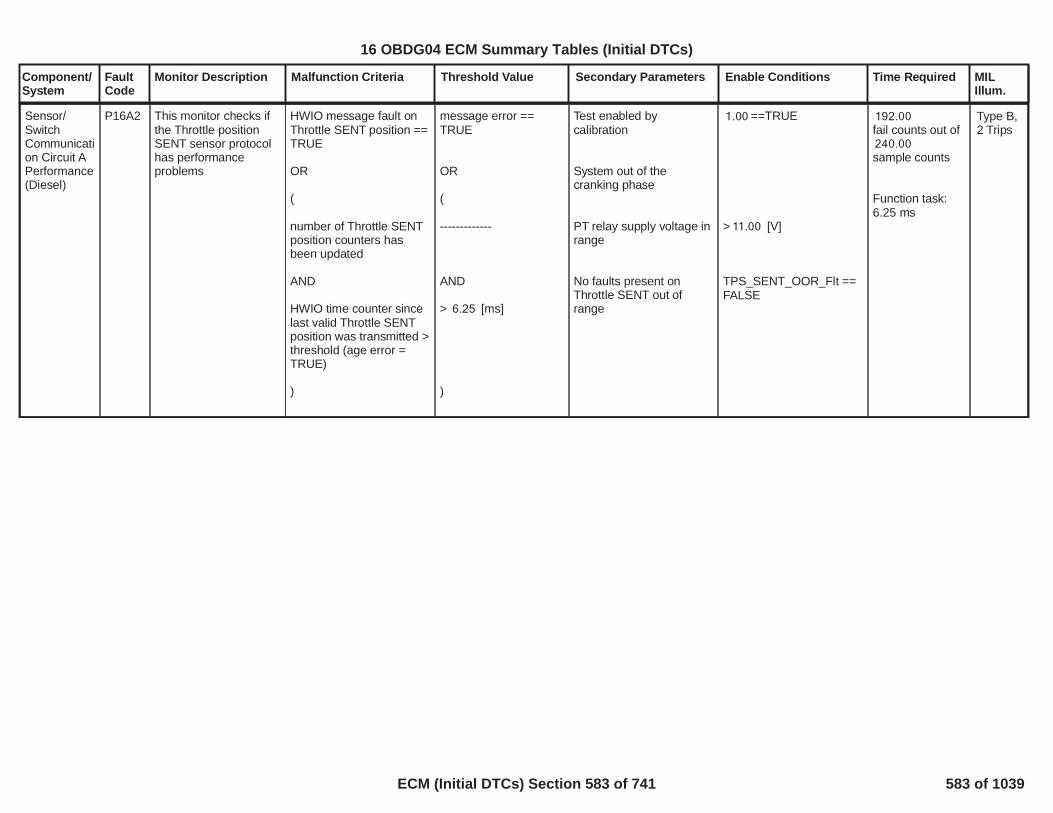
Component/System
FaultCode
Monitor Description Malfunction Criteria Threshold Value Secondary Parameters Enable Conditions Time Required MILIllum.
Sensor/SwitchCommunication Circuit APerformance(Diesel)
P16A2 This monitor checks ifthe Throttle positionSENT sensor protocolhas performanceproblems
HWIO message fault onThrottle SENT position ==TRUE
OR
(
number of Throttle SENTposition counters hasbeen updated
AND
HWIO time counter sincelast valid Throttle SENTposition was transmitted >threshold (age error =TRUE)
)
message error ==TRUE
OR
(
-------------
AND
> [ms]6.25
)
Test enabled bycalibration
System out of thecranking phase
PT relay supply voltage inrange
No faults present onThrottle SENT out ofrange
==TRUE1.00
> [V]11.00
==TPS_SENT_OOR_FltFALSE
192.00fail counts out of240.00sample counts
Function task:6.25 ms
Type B,2 Trips
584
16 OBDG04 ECM Summary Tables (Initial DTCs)
ECM (Initial DTCs) Section 583 of 741 583 of 1039

Component/System
FaultCode
Monitor Description Malfunction Criteria Threshold Value Secondary Parameters Enable Conditions Time Required MILIllum.
Sensor/SwitchCommunication Circuit BLow
P16B0 This monitor checks ifthe VGT position SENTsensor protocol is outof range low
HWIO counter of validVGT SENT positionindications no longerupdated > threshold (ageerror = TRUE)
AND
HWIO VGT SENT positionprotocol status
> [s]2.50
AND
== FALSE
Test enabled bycalibration
System out of thecranking phase
Run Crank relay supplyvoltage in range
Run crank active
==TRUE1.00
> [V]11.00
200.00fail counts out of250.00sample counts
Function task:6.25 ms
Type B,2 Trips
585
16 OBDG04 ECM Summary Tables (Initial DTCs)
ECM (Initial DTCs) Section 584 of 741 584 of 1039

Component/System
FaultCode
Monitor Description Malfunction Criteria Threshold Value Secondary Parameters Enable Conditions Time Required MILIllum.
Sensor/SwitchCommunication Circuit BHigh
P16B1 This monitor checks ifthe VGT position SENTsensor protocol is outof range high
HWIO time counter sincelast valid VGT SENTposition was transmitted >threshold (age error =TRUE)
AND
HWIO VGT SENT positionprotocol status
> [s]2.50
AND
== TRUE
Test enabled bycalibration
System out of thecranking phase
Run Crank relay supplyvoltage in range
Run crank active
==TRUE1.00
> [V]11.00
200.00fail counts out ofsample counts250.00
Function task:6.25 ms
Type B,2 Trips
586
16 OBDG04 ECM Summary Tables (Initial DTCs)
ECM (Initial DTCs) Section 585 of 741 585 of 1039

Component/System
FaultCode
Monitor Description Malfunction Criteria Threshold Value Secondary Parameters Enable Conditions Time Required MILIllum.
Sensor/SwitchCommunication Circuit BPerformance
P16B2 This monitor checks ifthe VGT position SENTsensor protocol hasperformance problems
HWIO message fault onVGTSENT position ==TRUE
OR
(
number of VGT SENTposition counters hasbeen updated
AND
HWIO time counter sincelast valid VGTSENTposition was transmitted >threshold (age error =TRUE)
)
message error ==TRUE
OR
(
-----------
AND
> [s]2.50
)
Test enabled bycalibration
System out of thecranking phase
Run Crank relay supplyvoltage in range
Run crank active
No faults present on VGTSENT out of range
==TRUE1.00
> [V]11.00
VGT_SENT_PerfFlt
200.00fail counts out of250.00sample counts
Function task:6.25 ms
Type B,2 Trips
587
16 OBDG04 ECM Summary Tables (Initial DTCs)
ECM (Initial DTCs) Section 586 of 741 586 of 1039

Component/System
FaultCode
Monitor Description Malfunction Criteria Threshold Value Secondary Parameters Enable Conditions Time Required MILIllum.
Turbocharger BoostControlMotor HighCurrent
P16FA This monitor checks ifan excessive currentflows through the VGTDC-Motor (e.g. shuntcircuit between load,VGTDC-Motor internalfaults, etc).
Error interface providedby HWIO
== TRUE Test enabled bycalibration
System out of thecranking phase
PT relay supply voltage inrange
Error interface providedby HWIO !=INDETERMINATE
==TRUE1.00
> [V]11.00
24.00fail counts out ofsample counts30.00
Function task:100 ms
Type A,1 Trips
588
16 OBDG04 ECM Summary Tables (Initial DTCs)
ECM (Initial DTCs) Section 587 of 741 587 of 1039

Component/System
FaultCode
Monitor Description Malfunction Criteria Threshold Value Secondary Parameters Enable Conditions Time Required MILIllum.
DieselParticulateFilterEfficiencyBelowThresholdBank 1
P2002 This diagnosis detectsa cracked DieselParticulate FIlter
The expected sensorregeneration time interval,i.e. the level of sootcalculated by a predictionmodel during a timeaveraged over a numberof different diagnosticruns is
> * 0,00625 s1.00
< 1.30
Test enabled bycalibration(TRUE--> enableFALSE --> disable)
Ignition voltage in rangefor a time
Engine running or enginecranking or in auto-stopphase
No faults on soot sensor
DPF soot loading (rankedmodel)
Engine out soot modelrealiableNote: the not reliabilityshall be verified for 1 sbefore to be declared
No faults on downstreamDPF temperature sensoror model
No faults on downstreamDPF mass airflow
No faults on engine outsoot model
Ambient temperature
During sensormeasurement phase,Number of Autostopevents
During sensor
1.00
> s5.00
NOT ( )SOT_SootSnsrFlt
> %0.00
NOTEXM_PM_TurbFlowNotRlb
NOT( )DPF_TempDPF_DwnFlt
SOT_TotExhSootSnsrVld
SOT_PM_DPF_UpVld
> °C-7.00
< 20.00
The number ofruns to performthe diagnostictest >= 1.00
Type B,2 Trips
589
16 OBDG04 ECM Summary Tables (Initial DTCs)
ECM (Initial DTCs) Section 588 of 741 588 of 1039

Component/System
FaultCode
Monitor Description Malfunction Criteria Threshold Value Secondary Parameters Enable Conditions Time Required MILIllum.
measurement phase,Duration of Autostopphase < s200.00
590
16 OBDG04 ECM Summary Tables (Initial DTCs)
ECM (Initial DTCs) Section 589 of 741 589 of 1039

Component/System
FaultCode
Monitor Description Malfunction Criteria Threshold Value Secondary Parameters Enable Conditions Time Required MILIllum.
Exahust gas temperatureon DPF Upstream (EGT4)
In Regeneration mode:> [°C]900.00
In Normal mode :> [°C]900.00
Test enabled bycalibration(TRUE--> enableFALSE --> disable)
and with
Battery voltage
and with
Engine running
and with
No fault on DPFUpstream Temperaturesensor
[Boolean]1.00
> [V]11.00
== TRUE [Boolean]
EGT_SnsrDPF_UpFlt[Boolean]
In Normalmode:
fail60.00samples out of
samples75.00
In Regenerationmode :
fail60.00samples out of
samples75.00
Function task:100ms
DieselParticulateFilter OverTemperatureBank 1
P200C This diagnosis verify ifthe exahust gastemperature on eitherDPF Upstream(EGT_DPF_Up) orDPF Downstream(EGT_DPF_Dwn) isabove its maximumallowed temperature
Type A,1 Trips
Exahust gas temperatureon DPF Downstream(EGT5)
In Regeneration mode:> [°C]900.00
In Normal mode :> [°C]900.00
Test enabled bycalibration(TRUE--> enableFALSE --> disable)
and with
Battery voltage
and with
Engine running
and with
No fault on DPFDownstream Temperaturesensor
[Boolean]1.00
> [V]11.00
== TRUE [Boolean]
EGT_SnsrDPF_DwnFlt[Boolean]
In Normalmode: fail60.00samples out of
samples75.00
In Regenerationmode:
fail60.00samples out of
samples75.00
Function task:100ms
591
16 OBDG04 ECM Summary Tables (Initial DTCs)
ECM (Initial DTCs) Section 590 of 741 590 of 1039

Component/System
FaultCode
Monitor Description Malfunction Criteria Threshold Value Secondary Parameters Enable Conditions Time Required MILIllum.
CatalystSystem OverTemperatureBank 1
P200E This diagnosis verify ifthe exahust gastemperature on ccDOCDownstream(EGT_DOC1_Dwn) isabove its maximumallowed temperature
Exahust gas temperatureon ccDOC Downstream(EGT2)
In Regeneration mode:> [°C]900.00
In Normal mode :> [°C]900.00
Test enabled bycalibration(TRUE--> enableFALSE --> disable)
and with
Battery voltage
and with
Engine running
and with
No fault on ccDOCDownstreamTemperature sensor(EGT2)
1.00
> 11.00
== TRUE
EGT_SnsrCatDwnFlt
In Normalmode:
fail100.00samples out of
samples125.00
In Regenerationmode :
fail100.00samples out of
samples125.00
Function task:100ms
Type A,1 Trips
592
16 OBDG04 ECM Summary Tables (Initial DTCs)
ECM (Initial DTCs) Section 591 of 741 591 of 1039

Component/System
FaultCode
Monitor Description Malfunction Criteria Threshold Value Secondary Parameters Enable Conditions Time Required MILIllum.
Exhaust GasTemperatureSensorCircuit LowBank 1Sensor 2
P2032 This diagnosis verify ifthe exhaust gastemperature 2 (EGT2)sensor signal is shortedto GND
EGT2 output resistancevalue
<[Ohm]160.00
Test enabled bycalibration(TRUE--> enableFALSE --> disable)
and with
Engine cranking
and with
Battery voltage
and with
key on
[Boolean]1
== FALSE
> [V]11.00
== TRUE
10fail samples over20samples
Function task:100ms
Type B,2 Trips
593
16 OBDG04 ECM Summary Tables (Initial DTCs)
ECM (Initial DTCs) Section 592 of 741 592 of 1039

Component/System
FaultCode
Monitor Description Malfunction Criteria Threshold Value Secondary Parameters Enable Conditions Time Required MILIllum.
Exhaust GasTemperatureSensorCircuit HighBank 1Sensor 2
P2033 This diagnosis verify ifthe exhaust gastemperature 2 (EGT2)signal is shorted topower supply or it is inopen circuit
EGT2 output resistancevalue
> [Ohm]900.00 Test enabled bycalibration(TRUE--> enableFALSE --> disable)
and with
Engine cranking
and with
Battery voltage
and with
key on
[Boolean]1
== FALSE
> [V]11.00
==TRUE
fail samples10over
samples20
Function task:100ms
Type B,2 Trips
594
16 OBDG04 ECM Summary Tables (Initial DTCs)
ECM (Initial DTCs) Section 593 of 741 593 of 1039

Component/System
FaultCode
Monitor Description Malfunction Criteria Threshold Value Secondary Parameters Enable Conditions Time Required MILIllum.
ReductantLevel SensorCircuit LowVoltage
P203C This diagnosis verifiesif an short to ground oropen circuit occurred inthe DEF level sensor
DEF level sensor rawsignal is below acalibrated threshold
VeSCRR_Pct_DEF_LevelRaw < 2.00
Test enabled bycalibration
Key on (OR enginerunning)
Engine is not cranking
Battery voltage
No loss of CANcomunication
== TRUE1.00
VePMDR_b_RunCrankActive==TRUE
VeEMDR_b_EngModeCrank == FALSE
> [V]11.00(VeLVTR_b_PT_RelayInRange== TRUE)
U010E, LostCommunication WithReductant Control Module(SCR)(GetCANR_b_LostComm_FltN= FALSE)
40.00
failures out of
50.00
samples
Time basis =100ms
Type A,1 Trips
595
16 OBDG04 ECM Summary Tables (Initial DTCs)
ECM (Initial DTCs) Section 594 of 741 594 of 1039

Component/System
FaultCode
Monitor Description Malfunction Criteria Threshold Value Secondary Parameters Enable Conditions Time Required MILIllum.
ReductantLevel SensorCircuit HighVoltage
P203D This diagnosis verifiesthat the short to batteryoccurred in the DEFlevel sensor
DEF level sensor rawsignal is above acalibrated threshold
VeSCRR_Pct_DEF_LevelRaw > 95.00
Test enabled bycalibration
Key on (OR enginerunning)
Engine is not cranking
Battery voltage
No loss of CANcomunication
== TRUE1.00
VePMDR_b_RunCrankActive==TRUE
VeEMDR_b_EngModeCrank == FALSE
> [V]11.00(VeLVTR_b_PT_RelayInRange== TRUE)
U010E, LostCommunication WithReductant Control Module(SCR)(GetCANR_b_LostComm_FltN= FALSE)
40.00
failures out of
50.00
samples
Time basis =100ms
Type B,2 Trips
596
16 OBDG04 ECM Summary Tables (Initial DTCs)
ECM (Initial DTCs) Section 595 of 741 595 of 1039

Component/System
FaultCode
Monitor Description Malfunction Criteria Threshold Value Secondary Parameters Enable Conditions Time Required MILIllum.
ReductantInjectorCircuit /Open Bank 1Unit 1
P2047 This diagnosis verifiesif a DEF dosing valveopen circuit occurred
HWIO interfaceDEFMV_OPEN = Fault
VeHWIO_e_DEFMV_Open ==CeSCRR_e_Fault
Test enabled bycalibration
Key on (OR enginerunning)
Engine is not cranking
Battery voltage
HWIO interfaceDEFMV_OPEN differentfrom INDETERMINATE
1.00
VePMDR_b_RunCrankActive==TRUE
VeEMDR_b_EngModeCrank == FALSE
> [V]11.00(VeLVTR_b_PT_RelayInRange== TRUE)
VeHWIO_e_DEFMV_Open !=CeSCRR_e_Indeterminate
30.00
failures out of
60.00
samples
Time basis =100ms
Type A,1 Trips
597
16 OBDG04 ECM Summary Tables (Initial DTCs)
ECM (Initial DTCs) Section 596 of 741 596 of 1039

Component/System
FaultCode
Monitor Description Malfunction Criteria Threshold Value Secondary Parameters Enable Conditions Time Required MILIllum.
ReductantInjectorCircuit LowBank 1 Unit1
P2048 This diagnosis verifiesif a DEF dosing valvelow side short toground occurred
HWIO interfaceDEFMV_GROUND_SHORT = Fault
VeHWIO_e_DEFMV_Gsht ==CeSCRR_e_Fault
Test enabled bycalibration
Key on (OR enginerunning)
Engine is not cranking
Battery voltage
HWIO interfaceDEFMV_GROUND_SHORT different fromINDETERMINATE
1.00
VePMDR_b_RunCrankActive==TRUE
VeEMDR_b_EngModeCrank == FALSE
> [V]11.00(VeLVTR_b_PT_RelayInRange== TRUE)
VeHWIO_e_DEFMV_Gsht !=CeSCRR_e_Indeterminate
30.00
failures out of
60.00
samples
Time basis =100ms
Type A,1 Trips
598
16 OBDG04 ECM Summary Tables (Initial DTCs)
ECM (Initial DTCs) Section 597 of 741 597 of 1039

Component/System
FaultCode
Monitor Description Malfunction Criteria Threshold Value Secondary Parameters Enable Conditions Time Required MILIllum.
ReductantInjectorCircuit HighBank 1 Unit1
P2049 This diagnosis verifiesif a DEF dosing valvelow side short tobattery occurred
HWIO interfaceDEFMV_POWER_SHORT = Fault
VeHWIO_e_DEFMV_Psht ==CeSCRR_e_Fault
Test enabled bycalibration
Key on (OR enginerunning)
Engine is not cranking
Battery voltage
HWIO interfaceDEFMV_ENABLE_POWER_SHORT different fromINDETERMINATE
1.00
VePMDR_b_RunCrankActive==TRUE
VeEMDR_b_EngModeCrank == FALSE
> [V]11.00(VeLVTR_b_PT_RelayInRange== TRUE)
VeHWIO_e_DEFMV_Psht!=
CeSCRR_e_Indeterminate
30.00
failures out of
60.00
samples
Time basis =100ms
Type A,1 Trips
599
16 OBDG04 ECM Summary Tables (Initial DTCs)
ECM (Initial DTCs) Section 598 of 741 598 of 1039
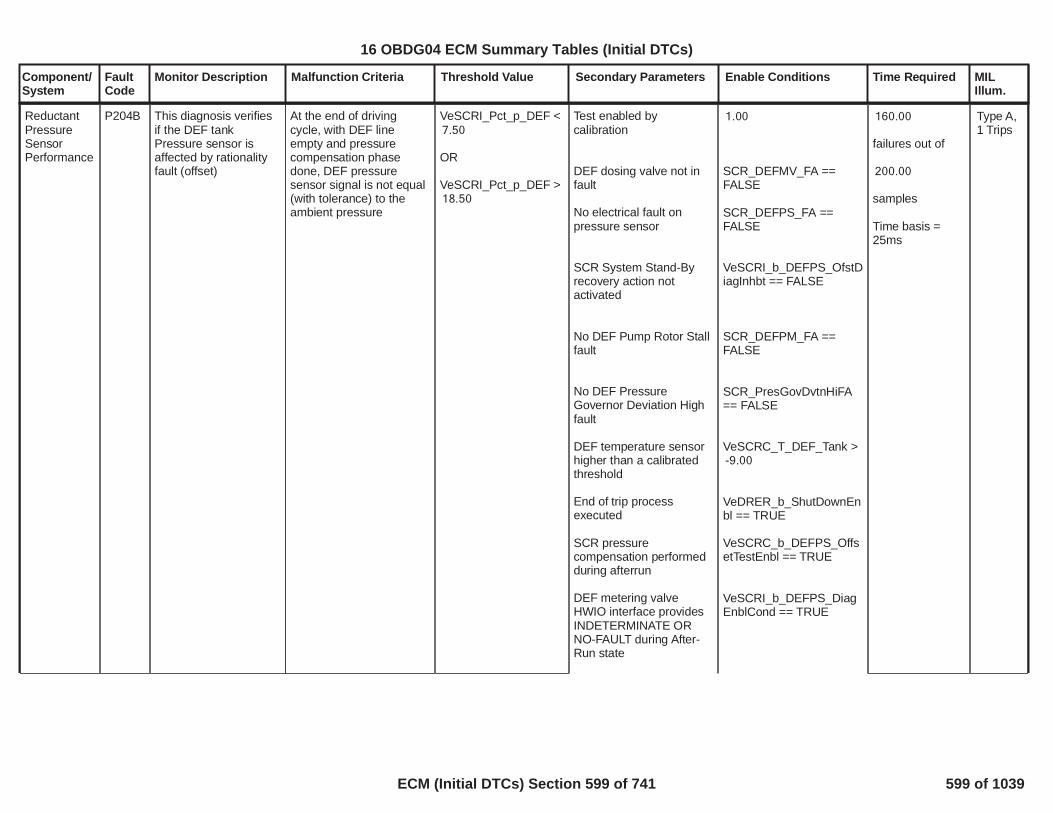
Component/System
FaultCode
Monitor Description Malfunction Criteria Threshold Value Secondary Parameters Enable Conditions Time Required MILIllum.
ReductantPressureSensorPerformance
P204B This diagnosis verifiesif the DEF tankPressure sensor isaffected by rationalityfault (offset)
At the end of drivingcycle, with DEF lineempty and pressurecompensation phasedone, DEF pressuresensor signal is not equal(with tolerance) to theambient pressure
VeSCRI_Pct_p_DEF <7.50
OR
VeSCRI_Pct_p_DEF >18.50
Test enabled bycalibration
DEF dosing valve not infault
No electrical fault onpressure sensor
SCR System Stand-Byrecovery action notactivated
No DEF Pump Rotor Stallfault
No DEF PressureGovernor Deviation Highfault
DEF temperature sensorhigher than a calibratedthreshold
End of trip processexecuted
SCR pressurecompensation performedduring afterrun
DEF metering valveHWIO interface providesINDETERMINATE ORNO-FAULT during After-Run state
1.00
==SCR_DEFMV_FAFALSE
==SCR_DEFPS_FAFALSE
VeSCRI_b_DEFPS_OfstDiagInhbt == FALSE
==SCR_DEFPM_FAFALSE
SCR_PresGovDvtnHiFA== FALSE
VeSCRC_T_DEF_Tank >-9.00
VeDRER_b_ShutDownEnbl == TRUE
VeSCRC_b_DEFPS_OffsetTestEnbl == TRUE
VeSCRI_b_DEFPS_DiagEnblCond == TRUE
160.00
failures out of
200.00
samples
Time basis =25ms
Type A,1 Trips
600
16 OBDG04 ECM Summary Tables (Initial DTCs)
ECM (Initial DTCs) Section 599 of 741 599 of 1039

Component/System
FaultCode
Monitor Description Malfunction Criteria Threshold Value Secondary Parameters Enable Conditions Time Required MILIllum.
601
16 OBDG04 ECM Summary Tables (Initial DTCs)
ECM (Initial DTCs) Section 600 of 741 600 of 1039

Component/System
FaultCode
Monitor Description Malfunction Criteria Threshold Value Secondary Parameters Enable Conditions Time Required MILIllum.
ReductantPressureSensorCircuit LowVoltage
P204C This diagnosis verifiesthat the DEF pressuresensor is affected byopen circuit or shortcircuit to ground
DEF pressure sensor rawsignal is below acalibrated threshold
VeSCRI_Pct_p_DEF <5.00
Test enabled bycalibration
Battery voltage > 11V
Key on
Engine is not cranking
== TRUE1.00
> [V]11.00(VeLVTR_b_PT_RelayInRange== TRUE)
VePMDR_b_RunCrankActive==TRUE
VeEMDR_b_EngModeCrank == FALSE
100.00
failures out of
125.00
samples
Time basis =25ms
Type A,1 Trips
602
16 OBDG04 ECM Summary Tables (Initial DTCs)
ECM (Initial DTCs) Section 601 of 741 601 of 1039

Component/System
FaultCode
Monitor Description Malfunction Criteria Threshold Value Secondary Parameters Enable Conditions Time Required MILIllum.
ReductantPressureSensorCircuit HighVoltage
P204D This diagnosis verifiesthat the DEF pressuresensor is affected byshort circuit to battery
DEF pressure sensor rawsignal is above acalibrated threshold
VeSCRI_Pct_p_DEF >98.00
Test enabled bycalibration
Battery voltage > 11V
Key on
Engine is not cranking
== TRUE1.00
> [V]11.00(VeLVTR_b_PT_RelayInRange== TRUE)
VePMDR_b_RunCrankActive==TRUE
VeEMDR_b_EngModeCrank == FALSE
100.00
failures out of
125.00
Time basis =25ms
Type A,1 Trips
603
16 OBDG04 ECM Summary Tables (Initial DTCs)
ECM (Initial DTCs) Section 602 of 741 602 of 1039

Component/System
FaultCode
Monitor Description Malfunction Criteria Threshold Value Secondary Parameters Enable Conditions Time Required MILIllum.
ReductantTankTemperatureSensorPerformance
P205B This diagnosis verifiesthat the DEF tanktemperature sensor isaffected by rationalityfault (gain or offset)
Difference betweentemperature sensor signaland average temperaturefrom EGTR is outside acalibrated range
abs(VeEGTR_T_Avg -VeSCRI_T_DEF_TankUndfltd) >40.00
Test enabled bycalibration
Battery voltage
Key on (OR enginerunning)
No loss of CANcomunication
Average temperaturecalculated in EGTR isavailable
Engine speed = 0 rpm
No electrical fault on DEFtemperature sensor
Time elapsed since lastkey off > threshold
Tank Refill is not detected
== TRUE1.00
> [V]11.00(VeLVTR_b_PT_RelayInRange== TRUE)
VePMDR_b_RunCrankActive==TRUE
U010E, LostCommunication WithReductant Control Module(SCR)(GetCANR_b_LostComm_FltN= FALSE)
VeEGTR_b_PlTestEnbl== TRUE
VeEPSR_b_EngMvmtDetected == FALSE
==SCR_DEFTS_FAFALSE
VeEMDR_t_EngModeNotRun > 28,800.00ANDVeEMDR_b_EngModeNotRunTmErr == FALSE
VeSCRC_b_TankRefillIgnCycle ==FALSEORVeSCRC_b_TankRefillDtctn == FALSE
8.00
failures out of
10.00
samples
Time basis =500ms
Type A,1 Trips
604
16 OBDG04 ECM Summary Tables (Initial DTCs)
ECM (Initial DTCs) Section 603 of 741 603 of 1039

Component/System
FaultCode
Monitor Description Malfunction Criteria Threshold Value Secondary Parameters Enable Conditions Time Required MILIllum.
DEF temperature sensorsignal is not equal to theDEF freezing temperature(with tollerance)
VeSCRC_T_DEF_Tank <( + )-90.00 1.00
AND
VeSCRC_T_DEF_Tank >( - )-90.00 1.00
605
16 OBDG04 ECM Summary Tables (Initial DTCs)
ECM (Initial DTCs) Section 604 of 741 604 of 1039

Component/System
FaultCode
Monitor Description Malfunction Criteria Threshold Value Secondary Parameters Enable Conditions Time Required MILIllum.
ReductantTankTemperatureSensorCircuit LowVoltage
P205C This diagnosis verifiesthat the DEF tanktemperature sensor isaffected by open circuitor short circuit toground
DEF temperature sensorraw signal is below acalibrated threshold
VeSCRI_T_DEF_TankUndfltd < 200.00
Test enabled bycalibration
Battery voltage
Key on (OR enginerunning)
Engine is not cranking
No loss of CANcomunication
DEF Tank heater not infault
1.00
> [V]11.00(VeLVTR_b_PT_RelayInRange== TRUE)
VePMDR_b_RunCrankActive==TRUE
VeEMDR_b_EngModeCrank == FALSE
U010E, LostCommunication WithReductant Control Module(SCR)(GetCANR_b_LostComm_FltN= FALSE)
==SCR_DEFTH_FAFALSE
8.00
failures out of
10.00
samples
Time basis =500ms
Type A,1 Trips
606
16 OBDG04 ECM Summary Tables (Initial DTCs)
ECM (Initial DTCs) Section 605 of 741 605 of 1039

Component/System
FaultCode
Monitor Description Malfunction Criteria Threshold Value Secondary Parameters Enable Conditions Time Required MILIllum.
ReductantTankTemperatureSensorCircuit HighVoltage
P205D This diagnosis verifiesthat the DEF tanktemperature sensor isaffected by short circuitto battery
DEF temperature sensorraw signal is above acalibrated threshold
VeSCRI_T_DEF_TankUndfltd > 60,000.00
Test enabled bycalibration
Battery voltage
Key on (OR enginerunning)
Engine is not cranking
No loss of CANcomunication
DEF Tank heater not infault
Defrost phase complete
1.00
> [V]11.00(VeLVTR_b_PT_RelayInRange== TRUE)
VePMDR_b_RunCrankActive==TRUE
VeEMDR_b_EngModeCrank == FALSE
U010E, LostCommunication WithReductant Control Module(SCR)(GetCANR_b_LostComm_FltN= FALSE)
==SCR_DEFTH_FAFALSE
VeSCRC_b_DefrostComplete == TRUE
8.00
failures out of
10.00
samples
Time basis =500ms
Type A,1 Trips
607
16 OBDG04 ECM Summary Tables (Initial DTCs)
ECM (Initial DTCs) Section 606 of 741 606 of 1039

Component/System
FaultCode
Monitor Description Malfunction Criteria Threshold Value Secondary Parameters Enable Conditions Time Required MILIllum.
DEFtemperaturesensor SelfCorrelateddiagnostic
P205E This diagnosis verifiesthat the DEFtemperature sensorsignal has not aplausible time evolution
DEF temperature sensorsignal time evolution notplausible (intermittentsignal)
VeSCRI_T_DEF_TankUndfltd >VeSCRI_T_DEFTS_SelfCorrHiTrhs
OR
VeSCRI_T_DEF_TankUndfltd <VeSCRI_T_DEFTS_SelfCorrLoTrhs
Test enabled bycalibration
Run Crank active
Run Crank in range
No loss of CANcomunication
No electrical fault on tankTemperature sensor
1.00
VePMDR_b_RunCrankActive == TRUE
VePMDR_b_RunCrankInRange == TRUE
U010E, LostCommunication WithReductant Control Module(SCR)(GetCANR_b_LostComm_FltN= FALSE)
SCR_DEFTS_ElecFltSt== FALSE
8.00
failures out of
10.00
samples
Time basis =500ms
608
16 OBDG04 ECM Summary Tables (Initial DTCs)
ECM (Initial DTCs) Section 607 of 741 607 of 1039

Component/System
FaultCode
Monitor Description Malfunction Criteria Threshold Value Secondary Parameters Enable Conditions Time Required MILIllum.
Exhaust GasTemperatureSensorCircuitIntermittentBank 1Sensor 1
P2081 This diagnosis verify ifthe EGT1 temperaturesensor signal(difference betweentwo consecutive signalsamples) variation istoo big
|EGT4 output reistance -EGT4 output resistanceold|
< [Ohm]10.00 Test enabled bycalibration
and with
Engine running
and with
Engine cranking
and with
Battery voltage
and with
key on
and with
No electrical faults onEGT1 sensor in and logic
[Boolean]1
== TRUE
== FALSE
> [V]11.00
== TRUE
EGT_ExhGas1_TFTKOand withEGT_ExhGas1_FA
fail samples20out of 40samples
Function task:100ms
Type B,2 Trips
609
16 OBDG04 ECM Summary Tables (Initial DTCs)
ECM (Initial DTCs) Section 608 of 741 608 of 1039

Component/System
FaultCode
Monitor Description Malfunction Criteria Threshold Value Secondary Parameters Enable Conditions Time Required MILIllum.
Exhaust GasTemperatureSensorCircuitIntermittentBank 1Sensor 2
P2085 This diagnosis verify ifthe EGT2 temperaturesensor signal(difference betweentwo consecutive signalsamples) variation istoo big
|EGT2 output reistance -EGT2 output resistanceold|
< [Ohm]10.00 Test enabled bycalibration
and with
Engine running
and with
Engine cranking
and with
key on
and with
Battery voltage
and with
No electrical faults onEGT2 sensor in and logic
[Boolean]1
== TRUE
== FALSE
==TRUE
> [V]11.00
EGT_ExhGas2_TFTKOand withEGT_ExhGas2_FA
fail samples20out of 40samples
Function task:100ms
Type B,2 Trips
610
16 OBDG04 ECM Summary Tables (Initial DTCs)
ECM (Initial DTCs) Section 609 of 741 609 of 1039

Component/System
FaultCode
Monitor Description Malfunction Criteria Threshold Value Secondary Parameters Enable Conditions Time Required MILIllum.
ReductantPumpControlCircuit
P208A This diagnosis verifiesthat the DEF pumpphases are open
Motor Pump Phase OpenError status provided byDEF control module ==FAULT
VeSCRR_e_PmpMtrOpen==FAULT
Test enabled bycalibration
Battery voltage
Key on (OR enginerunning)
Engine is not cranking
No loss of CANcomunication
Motor Pump Phase OpenError status provided byDEF control moduledifferent fromindeterminate
1.00
> [V]11.00(VeLVTR_b_PT_RelayInRange== TRUE)
VePMDR_b_RunCrankActive==TRUE
VeEMDR_b_EngModeCrank == FALSE
U010E, LostCommunication WithReductant Control Module(SCR)(GetCANR_b_LostComm_FltN= FALSE)
VeSCRR_e_PmpMtrOpen!= Indeterminate
20.00
failures out of
25.00
samples
Time basis =100ms
Type A,1 Trips
611
16 OBDG04 ECM Summary Tables (Initial DTCs)
ECM (Initial DTCs) Section 610 of 741 610 of 1039

Component/System
FaultCode
Monitor Description Malfunction Criteria Threshold Value Secondary Parameters Enable Conditions Time Required MILIllum.
ReductantPumpControlCircuit LowVoltage
P208C This diagnosis verifiesthat the DEF pumpphases are shorted toground
Motor Pump PhaseShorted To Ground Errorstatus provided by DEFcontrol module == FAULT
VeSCRR_e_PmpMtrShrtToGND==FAULT
Test enabled bycalibration
Battery voltage
Key on (OR enginerunning)
Engine is not cranking
No loss of CANcomunication
Motor Pump PhaseShorted To Ground Errorstatus provided by DEFcontrol module differentfrom indeterminate
1.00
> [V]11.00(VeLVTR_b_PT_RelayInRange== TRUE)
VePMDR_b_RunCrankActive==TRUE
VeEMDR_b_EngModeCrank == FALSE
U010E, LostCommunication WithReductant Control Module(SCR)(GetCANR_b_LostComm_FltN= FALSE)
VeSCRR_e_PmpMtrShrtToGND != Indeterminate
20.00
failures out of
25.00
samples
Time basis =100ms
Type A,1 Trips
612
16 OBDG04 ECM Summary Tables (Initial DTCs)
ECM (Initial DTCs) Section 611 of 741 611 of 1039

Component/System
FaultCode
Monitor Description Malfunction Criteria Threshold Value Secondary Parameters Enable Conditions Time Required MILIllum.
ReductantPumpControlCircuit HighVoltage
P208D This diagnosis verifiesthat the DEF pumpphases are shorted tobattery
Motor Pump PhaseShorted To Battery Errorstatus provided by DEFcontrol module == FAULT
VeSCRR_e_PmpMtrShrtToBatt==FAULT
Test enabled bycalibration
Battery voltage
Key on (OR enginerunning)
Engine is not cranking
No loss of CANcomunication
Motor Pump PhaseShorted To Battery Errorstatus provided by DEFcontrol module differentfrom indeterminate
1.00
> [V]11.00(VeLVTR_b_PT_RelayInRange== TRUE)
VePMDR_b_RunCrankActive==TRUE
VeEMDR_b_EngModeCrank == FALSE
U010E, LostCommunication WithReductant Control Module(SCR)(GetCANR_b_LostComm_FltN= FALSE)
VeSCRR_e_PmpMtrShrtToBatt != Indeterminate
20.00
failures out of
25.00
samples
Time basis =100ms
Type A,1 Trips
613
16 OBDG04 ECM Summary Tables (Initial DTCs)
ECM (Initial DTCs) Section 612 of 741 612 of 1039

Component/System
FaultCode
Monitor Description Malfunction Criteria Threshold Value Secondary Parameters Enable Conditions Time Required MILIllum.
ReductantHeater 1ControlCircuit
P20B9 This diagnosis verifiesif the DEF tank heateris affected by opencircuit
Tank Heater Open circuitstatus == FAULT
VeSCRR_e_HeatA_Open == FAULT
Test enabled bycalibration
Temperature used by theheating strategy to switchon the heaters < threshold
Battery voltage
Key on (OR enginerunning)
Engine is not cranking
No loss of CANcomunication
DEF Temperature sensornot in fault
Open circuit statusprovided by DEF controlmodule different fromindeterminate
1.00
min(VeOATR_T_OutsideAirNonEmiss,VeSCRC_T_DEF_Tank) <60.00
> [V]11.00(VeLVTR_b_PT_RelayInRange== TRUE)
VePMDR_b_RunCrankActive==TRUE
VeEMDR_b_EngModeCrank == FALSE
U010E, LostCommunication WithReductant Control Module(SCR)(GetCANR_b_LostComm_FltN= FALSE)
==SCR_DEFTS_FAFALSE
VeSCRR_e_HeatA_Open!= Indeterminate
8.00
failures out ofon
10.00
samples
Time basis =500ms
Type A,1 Trips
614
16 OBDG04 ECM Summary Tables (Initial DTCs)
ECM (Initial DTCs) Section 613 of 741 613 of 1039

Component/System
FaultCode
Monitor Description Malfunction Criteria Threshold Value Secondary Parameters Enable Conditions Time Required MILIllum.
DEF tankheaterplausibilitycheck
P20BA This diagnosis verifythet the DEF tankheater resistance valueis not plausible
DEF tank heaterresistance value notplausible (too differentfrom the nominal one)
(Heater supply voltage/Heater Current) >1.93
OR
(Heater supply voltage/Heater Current) <1.05
Test enabled bycalibration
Battery voltage
Key on (OR enginerunning)
Engine is not cranking
No SCR Power ModuleCAN loss ofcommunication
No electrical faultsaffecting the tank heater
Heating strategy isrequesting the Heater tobe activated
Time since heateractivation > Minimumcalibrateble threshold
Tank heater supply under-voltage fault not present
1.00
> [V]11.00(VeLVTR_b_PT_RelayInRange== TRUE)
VePMDR_b_RunCrankActive==TRUE
VeEMDR_b_EngModeCrank == FALSE
U010E, LostCommunication WithReductant Control Module(SCR)(GetCANR_b_LostComm_FltN= FALSE)
SCR_DEFTH_ElecFltSt== FALSE
Time since heateractivation > 1.00
SCR_TankHeatSplyVoltFA== FALSE
10.00
failures out of
12.00
samples
Time basis =500ms
615
16 OBDG04 ECM Summary Tables (Initial DTCs)
ECM (Initial DTCs) Section 614 of 741 614 of 1039

Component/System
FaultCode
Monitor Description Malfunction Criteria Threshold Value Secondary Parameters Enable Conditions Time Required MILIllum.
ReductantHeater 1ControlCircuit LowVoltage
P20BB This diagnosis verifiesif the DEF tank heateris affected by shortcircuit to ground
Tank Heater Short toGround Low Side / HighSide status == FAULT
VeSCRR_e_HeatA_LS_ShortToGND ==FAULT
OR
VeSCRR_e_HeatA_HS_ShortToGND ==FAULT
Test enabled bycalibration
Temperature used by theheating strategy to switchon the heaters < threshold
Battery voltage
Key on (OR enginerunning)
Engine is not cranking
No loss of CANcomunication
DEF Temperature sensornot in fault
Short to Ground LowSide / High Side statusprovided by DEF controlmodule different fromindeterminate
1.00
min(VeOATR_T_OutsideAirNonEmiss,VeSCRC_T_DEF_Tank) <60.00
> [V]11.00(VeLVTR_b_PT_RelayInRange== TRUE)
VePMDR_b_RunCrankActive==TRUE
VeEMDR_b_EngModeCrank == FALSE
U010E, LostCommunication WithReductant Control Module(SCR)(GetCANR_b_LostComm_FltN= FALSE)
==SCR_DEFTS_FAFALSE
VeSCRR_e_HeatA_LS_ShortToGND !=IndeterminateORVeSCRR_e_HeatA_HS_ShortToGND !=
8.00
failures out of
10.00
samples
Time basis =500ms
Type A,1 Trips
616
16 OBDG04 ECM Summary Tables (Initial DTCs)
ECM (Initial DTCs) Section 615 of 741 615 of 1039

Component/System
FaultCode
Monitor Description Malfunction Criteria Threshold Value Secondary Parameters Enable Conditions Time Required MILIllum.
Indeterminate
617
16 OBDG04 ECM Summary Tables (Initial DTCs)
ECM (Initial DTCs) Section 616 of 741 616 of 1039

Component/System
FaultCode
Monitor Description Malfunction Criteria Threshold Value Secondary Parameters Enable Conditions Time Required MILIllum.
ReductantHeater 1ControlCircuit HighVoltage
P20BC This diagnosis verifiesif the DEF tank heateris affected by shortcircuit to battery
Tank Heater Short toBattery Low Side / HighSide status == FAULT
VeSCRR_e_HeatA_LS_ShortToBatt ==FAULT
OR
VeSCRR_e_HeatA_HS_ShortToBatt ==FAULT
Test enabled bycalibration
Temperature used by theheating strategy to switchon the heaters < threshold
Battery voltage
Key on (OR enginerunning)
Engine is not cranking
No loss of CANcomunication
DEF Temperature sensornot in fault
Short to Battery LowSide / High Side statusprovided by DEF controlmodule different fromindeterminate
1.00
min(VeOATR_T_OutsideAirNonEmiss,VeSCRC_T_DEF_Tank) <60.00
> [V]11.00(VeLVTR_b_PT_RelayInRange== TRUE)
VePMDR_b_RunCrankActive==TRUE
VeEMDR_b_EngModeCrank == FALSE
U010E, LostCommunication WithReductant Control Module(SCR)(GetCANR_b_LostComm_FltN= FALSE)
==SCR_DEFTS_FAFALSE
VeSCRR_e_HeatA_LS_ShortToBatt !=IndeterminateORVeSCRR_e_HeatA_HS_ShortToBatt !=Indeterminate
8.00
failures out of
10.00
samples
Time basis =500ms
Type A,1 Trips
618
16 OBDG04 ECM Summary Tables (Initial DTCs)
ECM (Initial DTCs) Section 617 of 741 617 of 1039

Component/System
FaultCode
Monitor Description Malfunction Criteria Threshold Value Secondary Parameters Enable Conditions Time Required MILIllum.
619
16 OBDG04 ECM Summary Tables (Initial DTCs)
ECM (Initial DTCs) Section 618 of 741 618 of 1039

Component/System
FaultCode
Monitor Description Malfunction Criteria Threshold Value Secondary Parameters Enable Conditions Time Required MILIllum.
ReductantHeater 2ControlCircuit
P20BD This diagnosis verifiesif the DEF line heater isaffected by open circuit
Line Heater Open circuitstatus == FAULT
VeSCRR_e_HeatB_Open == FAULT
Test enabled bycalibration
Temperature used by theheating strategy to switchon the heaters < threshold
Battery voltage
Key on (OR enginerunning)
Engine is not cranking
No loss of CANcomunication
Open circuit statusprovided by DEF controlmodule different fromindeterminate
1.00
min(VeOATR_T_OutsideAirNonEmiss,VeSCRC_T_DEF_Tank) <60.00
> [V]11.00(VeLVTR_b_PT_RelayInRange== TRUE)
VePMDR_b_RunCrankActive==TRUE
VeEMDR_b_EngModeCrank == FALSE
U010E, LostCommunication WithReductant Control Module(SCR)(GetCANR_b_LostComm_FltN= FALSE)
VeSCRR_e_HeatB_Open!= Indeterminate
8.00
failures out of
10.00
samples
Time basis =500ms
Type A,1 Trips
620
16 OBDG04 ECM Summary Tables (Initial DTCs)
ECM (Initial DTCs) Section 619 of 741 619 of 1039

Component/System
FaultCode
Monitor Description Malfunction Criteria Threshold Value Secondary Parameters Enable Conditions Time Required MILIllum.
DEF lineheaterplausibilitycheck
P20BE This diagnosis verifythet the DEF lineheater resistance valueis not plausible
DEF line heaterresistance value notplausible (too differentfrom the nominal one)
(Heater supply voltage/Heater Current) >KeSCRI_R_DEFLH_ResOfstHiThrsh
OR
(Heater supply voltage/Heater Current) <KeSCRI_R_DEFLH_ResOfstLoThrsh
Test enabled bycalibration
Battery voltage
Key on (OR enginerunning)
Engine is not cranking
No loss of CANcomunication
No electrical faultsaffecting the line heater
Heating strategy isrequesting the Heater tobe activated
Time since heateractivation > Minimumcalibrateble threshold
Line heater supply under-voltage fault not present
1.00
> [V]11.00(VeLVTR_b_PT_RelayInRange== TRUE)
VePMDR_b_RunCrankActive==TRUE
VeEMDR_b_EngModeCrank == FALSE
U010E, LostCommunication WithReductant Control Module(SCR)(GetCANR_b_LostComm_FltN= FALSE)
SCR_DEFLH_ElecFltSt==FALSE
VeSCRR_b_HeatB_On== TRUE
Time since heateractivation > 1.00
SCR_LineHeatSplyVoltFA== FALSE
10.00
failures out of
12.00
samples
Time basis =500ms
621
16 OBDG04 ECM Summary Tables (Initial DTCs)
ECM (Initial DTCs) Section 620 of 741 620 of 1039

Component/System
FaultCode
Monitor Description Malfunction Criteria Threshold Value Secondary Parameters Enable Conditions Time Required MILIllum.
622
16 OBDG04 ECM Summary Tables (Initial DTCs)
ECM (Initial DTCs) Section 621 of 741 621 of 1039

Component/System
FaultCode
Monitor Description Malfunction Criteria Threshold Value Secondary Parameters Enable Conditions Time Required MILIllum.
ReductantHeater 2ControlCircuit LowVoltage
P20BF This diagnosis verifiesif the DEF line heater isaffected by short circuitto ground
Line Heater Short toGround Low Side / HighSide status == FAULT
VeSCRR_e_HeatB_LS_ShortToGND ==FAULT
OR
VeSCRR_e_HeatB_HS_ShortToGND ==FAULT
Test enabled bycalibration
Temperature used by theheating strategy to switchon the heaters < threshold
Battery voltage
Key on (OR enginerunning)
Engine is not cranking
No loss of CANcomunication
Short to Ground LowSide / High Side statusprovided by DEF controlmodule different fromindeterminate
1.00
min(VeOATR_T_OutsideAirNonEmiss,VeSCRC_T_DEF_Tank) <60.00
> [V]11.00(VeLVTR_b_PT_RelayInRange== TRUE)
VePMDR_b_RunCrankActive==TRUE
VeEMDR_b_EngModeCrank == FALSE
U010E, LostCommunication WithReductant Control Module(SCR)(GetCANR_b_LostComm_FltN= FALSE)
VeSCRR_e_HeatB_LS_ShortToGND !=IndeterminateORVeSCRR_e_HeatB_HS_ShortToGND !=Indeterminate
8.00
failures out of
10.00
samples
Time basis =500ms
Type A,1 Trips
623
16 OBDG04 ECM Summary Tables (Initial DTCs)
ECM (Initial DTCs) Section 622 of 741 622 of 1039

Component/System
FaultCode
Monitor Description Malfunction Criteria Threshold Value Secondary Parameters Enable Conditions Time Required MILIllum.
ReductantHeater 2ControlCircuit HighVoltage
P20C0 This diagnosis verifiesif the DEF line heater isaffected by short circuitto battery
Line Heater Short toBattery Low Side / HighSide status == FAULT
VeSCRR_e_HeatB_LS_ShortToBatt ==FAULT
OR
VeSCRR_e_HeatB_HS_ShortToBatt ==FAULT
Test enabled bycalibration
Temperature used by theheating strategy to switchon the heaters < threshold
Battery voltage
Key on (OR enginerunning)
Engine is not cranking
No loss of CANcomunication
Short to Battery LowSide / High Side statusprovided by DEF controlmodule different fromindeterminate
1.00
min(VeOATR_T_OutsideAirNonEmiss,VeSCRC_T_DEF_Tank) <60.00
> [V]11.00(VeLVTR_b_PT_RelayInRange== TRUE)
VePMDR_b_RunCrankActive==TRUE
VeEMDR_b_EngModeCrank == FALSE
U010E, LostCommunication WithReductant Control Module(SCR)(GetCANR_b_LostComm_FltN= FALSE)
VeSCRR_e_HeatB_LS_ShortToBatt !=IndeterminateORVeSCRR_e_HeatB_HS_ShortToBatt !=Indeterminate
8.00
failures out of
10.00
samples
Time basis =500ms
Type A,1 Trips
624
16 OBDG04 ECM Summary Tables (Initial DTCs)
ECM (Initial DTCs) Section 623 of 741 623 of 1039

Component/System
FaultCode
Monitor Description Malfunction Criteria Threshold Value Secondary Parameters Enable Conditions Time Required MILIllum.
ExhaustAftertreatment FuelInjector AControlCircuit/Open
P20CB This diagnosis detectsa HC InjectorCommand pin /wire inopen circuit
HC injector HWIO Openinterface fault
=TRUE (i.e. If thevoltage at the AUXINJoutput in the OFF statestays below Volt (1.95to 2.175V) and Volt(2.9 V to 3.2 V) for atime longer than tdiag(40 s to 70 s)
Shared High Side Driver 2commanded ON (i.e.closed)
Powertrain relay voltagein range;
failures48.00over 60.00samples
100 ms/sample
Type B,2 Trips
625
16 OBDG04 ECM Summary Tables (Initial DTCs)
ECM (Initial DTCs) Section 624 of 741 624 of 1039

Component/System
FaultCode
Monitor Description Malfunction Criteria Threshold Value Secondary Parameters Enable Conditions Time Required MILIllum.
ExhaustAftertreatment FuelInjector AControlCircuit Low
P20CD This diagnosis detectsa HC InjectorCommand pin /wireshortcut to ground
HC injector HWIO ShortTo Ground interface fault
=TRUE (i.e If thevoltage at the AUXINJoutput in the OFF statestays below Vltvt(1,95V to 2,175V) for atime longer than tdiag(40 s to 70 s)
Shared High Side Driver 2commanded ON (i.e.closed)
Powertrain relay voltagein range;
failures10.00over 30.00samples
100 ms/samples
Type B,2 Trips
626
16 OBDG04 ECM Summary Tables (Initial DTCs)
ECM (Initial DTCs) Section 625 of 741 625 of 1039

Component/System
FaultCode
Monitor Description Malfunction Criteria Threshold Value Secondary Parameters Enable Conditions Time Required MILIllum.
ExhaustAftertreatment FuelInjector AControlCircuit High
P20CE This diagnosis detectsa HC InjectorCommand pin /wireshortcut to powersupply
HC injector HWIO ShortTo Power Supplyinterface fault
=TRUE (i.e. If thecurrent through theAUXINJ output in theON state is higher thanIoc1 (8A to 11A) for atime longer than toc1 =36 s OR If the currentthrough the AUXINJoutput in ON state ishigher than Ioc2 (16 Ato 22A )
Powertrain relay voltagein range;
failures48.00over 60.00
100 ms/samples
Type B,2 Trips
627
16 OBDG04 ECM Summary Tables (Initial DTCs)
ECM (Initial DTCs) Section 626 of 741 626 of 1039

Component/System
FaultCode
Monitor Description Malfunction Criteria Threshold Value Secondary Parameters Enable Conditions Time Required MILIllum.
ReductantPressure TooLow
P20E8 This diagnosis verifiesthat the DEF pressureis lower than the targetvalue set by the control
(Test 1)Too attemps of pressurebuild up
(Test 2)DEF pressure setpoint -DEF measured pressure> calibrateable threshold
(Test 1)VeSCRC_b_PBU_Fail== TRUE(VeSCRC_Cnt_Defrost_NumOfCyc > )2.00
(Test 2)VeSCRC_p_DEF_PresCntrlrErr > 166.00
Test enabled bycalibration
Battery voltage
Key on (OR enginerunning)
Defrost complete
Motor pump rotor stallfault not present
No fault on DEF pressuresensor
No fault on PWMcommand
No electrical fault on DEFpump
No electrical fault on DEFdosing valve
Motor pump is no moregreen (some buildpressure attempts alreadyperformed since thebeginning of vehicle life)
1.00
> [V]11.00(VeLVTR_b_PT_RelayInRange== TRUE)
VeEMDR_b_EngModeCrank == FALSE
VeSCRC_b_DefrostComplete == TRUE
==SCR_PmpRtrStlFAFALSE
==SCR_DEFPS_FAFALSE
SCR_DEF_PumpCmdFA== FALSE
==SCR_DEFPM_FAFALSE
==SCR_DEFMV_FAFALSE
VeSCRD_b_DEF_PmpDegreenDiagEnbl == TRUE(EeSCRD_t_DEF_HydSysPrimingTm > )1,200.00
8.00
failures out of
10.00
samples
Time basis =500ms
Type A,1 Trips
628
16 OBDG04 ECM Summary Tables (Initial DTCs)
ECM (Initial DTCs) Section 627 of 741 627 of 1039

Component/System
FaultCode
Monitor Description Malfunction Criteria Threshold Value Secondary Parameters Enable Conditions Time Required MILIllum.
(Test 1)Pressure Build-Up state isreleased for the first timeduring the driving cycleANDTest-Pass OR Test-Failhas not been reported forthis test
(Test 2)DEF pressure control is inpressure closed loop
(Test 1)VeSCRC_b_BuildUpReleased == TRUE
AND
VeSCRD_b_PBU_ReportTestFailEnbl == TRUEANDVeSCRC_e_SCR_PresState !=CeSCRC_e_PresCntrlCLC
(Test 2)VeSCRC_e_SCR_PresState ==CeSCRC_e_PresCntrlCLC
629
16 OBDG04 ECM Summary Tables (Initial DTCs)
ECM (Initial DTCs) Section 628 of 741 628 of 1039

Component/System
FaultCode
Monitor Description Malfunction Criteria Threshold Value Secondary Parameters Enable Conditions Time Required MILIllum.
ReductantPressure TooHigh
P20E9 This diagnosis verifiesthat the DEF pressurein the dosing line is toohigh
Difference between "DEFline pressure" and "DEFline pressure set point" >Threshold
AND
Pump rotor speed <Threshold
VeSCRC_p_DEF_PresCntrlrErr * (-1) >150.00
AND
VeSCRR_n_PmpMtrSpd < 3,200.00
Test enabled bycalibration
Battery voltage
Battery voltage
Key on (OR enginerunning)
DEF pressure sensor notin fault
PWM_pump_commandnot in fault
DEF pressure controlstatus equal to “Closedloop control”
DEF motor pump not infault
Pump motor speed signalvalid on CAN
1.00
VePMDR_b_RunCrankActive==TRUE
> [V]11.00(VeLVTR_b_PT_RelayInRange== TRUE)
VeEMDR_b_EngModeCrank == FALSE
==SCR_DEFPS_FAFALSE
SCR_DEF_PumpCmdFA== FALSE
VeSCRC_e_SCR_PresState ==CeSCRC_e_PresCntrlCLC
VeSCRI_b_DEFPM_FltSt== FALSE
VeSCRR_b_PumpMotorProtectErr==FALSE
VeSCRR_b_PumpMotorRollCntErr==FALSE
100.00
failures out of
125.00
samples
Time basis =25ms
Type A,1 Trips
630
16 OBDG04 ECM Summary Tables (Initial DTCs)
ECM (Initial DTCs) Section 629 of 741 629 of 1039

Component/System
FaultCode
Monitor Description Malfunction Criteria Threshold Value Secondary Parameters Enable Conditions Time Required MILIllum.
631
16 OBDG04 ECM Summary Tables (Initial DTCs)
ECM (Initial DTCs) Section 630 of 741 630 of 1039

Component/System
FaultCode
Monitor Description Malfunction Criteria Threshold Value Secondary Parameters Enable Conditions Time Required MILIllum.
InjectorPositiveVoltageControlCircuitGroup 1 LowVoltage
P2147 This DTC detects ashort circuit to groundof the high side drivercircuit of the Bank 1(injector 1 and 4)
Voltage high across HighSide Driver of bank 1(injector 1 and 4) duringOn state indicates short toground
impedence betweenHS pin of injector 1and controller ground<= 0.5 [Ohm]
ORimpedence betweenHS pin of injector 4and controller ground<= 0.5 [Ohm]
Test enabled bycalibration;
andBattery voltage
andKey ON
andEngine is not cranking
andEngine Running
and
(FUL_OutEnblCyl_CiEPSR_CylinderA
ORFUL_OutEnblCyl_CiEPSR_CylinderC)
== [Boolean]1
> [V]11.00
-
-
>= [s]1.00
== 0 [Boolean]
== 0 [Boolean]
failures out of5samples10
100 ms/sampleContinuous
Type A,1 Trips
632
16 OBDG04 ECM Summary Tables (Initial DTCs)
ECM (Initial DTCs) Section 631 of 741 631 of 1039

Component/System
FaultCode
Monitor Description Malfunction Criteria Threshold Value Secondary Parameters Enable Conditions Time Required MILIllum.
InjectorPositiveVoltageControlCircuitGroup 1High Voltage
P2148 This DTC detects ashort circuit to highvoltage of high sidedriver circuit of theBank 1 (injector 1 and4)
Voltage low across Highside drive of bank 1(injector 1 and 4) duringoff state indicates short topower
impedence betweenHS pin of injector 1and controller power<= 0.5 [Ohm]
ORimpedence betweenHS pin of injector 4and controller power<= 0.5 [Ohm]
Test enabled bycalibration;
andBattery voltage
andKey ON
andEngine is not cranking
andEngine Running
and(FUL_OutEnblCyl_CiEPSR_CylinderAORFUL_OutEnblCyl_CiEPSR_CylinderC)
== [Boolean]1
> [V]11.00
-
-
>= [s]1.00
== 0 [Boolean]
== 0 [Boolean]
failures out of5samples10
100 ms/sampleContinuous
Type A,1 Trips
633
16 OBDG04 ECM Summary Tables (Initial DTCs)
ECM (Initial DTCs) Section 632 of 741 632 of 1039

Component/System
FaultCode
Monitor Description Malfunction Criteria Threshold Value Secondary Parameters Enable Conditions Time Required MILIllum.
ReductantPump ACurrent TooHigh
P214E This diagnosis verifiesthat the DEF pumpcurrent flow is too high
Motor High Current Errorstatus provided by DEFcontrol module ==FAULT
OR
Motor Current Limit Errorstatus provided by DEFcontrol module == FAULT
VeSCRR_e_PmpMtrHiCurrErr==FAULT
OR
VeSCRR_e_PmpMtrCurrLim=ACTIVE
Test enabled bycalibration
Battery voltage
Key on (OR enginerunning)
Engine is not cranking
No loss of CANcomunication
Motor High Current Errorstatus provided by DEFcontrol module differentfrom indeterminate
1.00
> [V]11.00(VeLVTR_b_PT_RelayInRange== TRUE)
VePMDR_b_RunCrankActive==TRUE
VeEMDR_b_EngModeCrank == FALSE
U010E, LostCommunication WithReductant Control Module(SCR)(GetCANR_b_LostComm_FltN= FALSE)
VeSCRR_e_PmpMtrHiCurrErr != Indeterminate
20.00
failures out of
25.00
samples
OR
20.00
failures out of
25.00
samples
Time basis =100ms
Type A,1 Trips
634
16 OBDG04 ECM Summary Tables (Initial DTCs)
ECM (Initial DTCs) Section 633 of 741 633 of 1039

Component/System
FaultCode
Monitor Description Malfunction Criteria Threshold Value Secondary Parameters Enable Conditions Time Required MILIllum.
InjectorPositiveVoltageControlCircuitGroup 2 LowVoltage
P2150 This DTC detects ashort circuit to groundof the high side drivercircuit of the Bank 2(injector 2 and 3)
Voltage high across HighSide Driver of bank 2(injector 2 and 3) duringOn state indicates short toground
impedence betweenHS pin of injector 2and controller ground<= 0.5 [Ohm]
OR
impedence betweenHS pin of injector 3and controller ground<= 0.5 [Ohm]
Test enabled bycalibration;
andBattery voltage
andKey ON
andEngine is not cranking
andEngine Running
and(FUL_OutEnblCyl_CiEPSR_CylinderDORFUL_OutEnblCyl_CiEPSR_CylinderB)
= [Boolean]1
> [V]11.00
-
-
>= [s]1.00
== 0 [Boolean]
== 0 [Boolean]
failures out of5samples10
100 ms/sampleContinuous
Type A,1 Trips
635
16 OBDG04 ECM Summary Tables (Initial DTCs)
ECM (Initial DTCs) Section 634 of 741 634 of 1039

Component/System
FaultCode
Monitor Description Malfunction Criteria Threshold Value Secondary Parameters Enable Conditions Time Required MILIllum.
InjectorPositiveVoltageControlCircuitGroup 2High Voltage
P2151 This DTC detects ashort circuit to highvoltage of high sidedriver circuit of theBank 2 (injector 2 and3)
Voltage low across Highside drive of bank 2(injector 2 and 3) duringoff state indicates short topower
impedence betweenHS pin of injector 2and controller power<= 0.5 [Ohm]
ORimpedence betweenHS pin of injector 3and controller power<= 0.5 [Ohm]
Test enabled bycalibration;
andBattery voltage
andKey ON
andEngine is not cranking
andEngine Running
and(FUL_OutEnblCyl_CiEPSR_CylinderDORFUL_OutEnblCyl_CiEPSR_CylinderB)
= [Boolean]1
> [V]11.00
-
-
>= [s]1.00
== 0 [Boolean]
== 0 [Boolean]
failures out of5samples10
100 ms/sampleContinuous
Type A,1 Trips
636
16 OBDG04 ECM Summary Tables (Initial DTCs)
ECM (Initial DTCs) Section 635 of 741 635 of 1039

Component/System
FaultCode
Monitor Description Malfunction Criteria Threshold Value Secondary Parameters Enable Conditions Time Required MILIllum.
SCRPMsupplyunder-voltagemonitoring
P21CB This diagnosis verifuesthat the SCRPM supplyvoltage is under thethreshold of correctfunctioning
SCRPM supply under-voltage
(System BatteryVoltage - SCRPMSupply Voltage value)>KeSCRI_U_DEFC_SplyVoltDiagThrs
Test enabled bycalibration
Powertrain relay in range
Run Crank Active
Cranking phase excluded
No SCR Power ModuleCAN loss ofcommunication
1.00
VePMDR_b_RunCrankInRange == TRUE
VePMDR_b_RunCrankActive== TRUE
VeEMDR_b_EngModeCrank== FALSE
U010E, LostCommunication WithReductant Control Module(SCR)(GetCANR_b_LostComm_FltN= FALSE)
40.00
failures out of
50.00
samples
Time basis =100ms
637
16 OBDG04 ECM Summary Tables (Initial DTCs)
ECM (Initial DTCs) Section 636 of 741 636 of 1039

Component/System
FaultCode
Monitor Description Malfunction Criteria Threshold Value Secondary Parameters Enable Conditions Time Required MILIllum.
NOx SensorCircuit LowBank 1Sensor 1
P2202 This diagnosis verifiesUpstream NOx sensorread out of range low
Check if the NOx1 sensorNOx concentration rawread is out of lower range:
NOx raw read < ppm-90
Fuel injection quantityrequest
Powertrain relay voltage
NOx Sensor Bus relay iscommanded ON
No failure on NOx1 CANcommunication
Sensor supply in range
Sensor dewpoint isreached
No current control failureon NOx1 sensor
Engine is running
No electrical failure onNOx1 sensor
Combustion modedependent enabling flag
> mm^310
> V11.00
TRUE
CAN_LostComm_FltN_BusB_NOxSnsr_A
> 10.8V
TRUE
NOX_NOx1_StBitChkFlt==FALSE
TRUE
NOX_Snsr1_ElecFA==FALSE
NOX_S1_OutRngMinCmbMode
Time counter:fails out of100
samples200
Task=25ms
Type B,2 Trips
638
16 OBDG04 ECM Summary Tables (Initial DTCs)
ECM (Initial DTCs) Section 637 of 741 637 of 1039

Component/System
FaultCode
Monitor Description Malfunction Criteria Threshold Value Secondary Parameters Enable Conditions Time Required MILIllum.
NOx SensorCircuit HighBank 1Sensor 1
P2203 This diagnosis verifiesUpstream NOx sensorread out of range high
Check if the NOx1 sensorNOx concentration rawread is out of higherrange:
NOx raw read > ppm2,500
Powertrain relay voltage
NOx Sensor Bus relay iscommanded ON
No failure on NOx1 CANcommunication
Sensor supply in range
Sensor dewpoint isreached
No current control failureon NOx1 sensor
Engine is running
No electrical failure onNOx1 sensor
Combustion modedependent enabling flag
> V11.00
TRUE
CAN_LostComm_FltN_BusB_NOxSnsr_A
> 10.8V
TRUE
NOX_NOx1_StBitChkFlt==FALSE
TRUE
NOX_Snsr1_ElecFA==FALSE
NOX_S1_OutRngMaxCmbMode
Time counter:fails out of100
samples200
Task=25ms
Type B,2 Trips
639
16 OBDG04 ECM Summary Tables (Initial DTCs)
ECM (Initial DTCs) Section 638 of 741 638 of 1039

Component/System
FaultCode
Monitor Description Malfunction Criteria Threshold Value Secondary Parameters Enable Conditions Time Required MILIllum.
NOx Sensor1 HeaterControlCircuit
P2205 This diagnosis verifiesUpstream NOx gen3sensor Heater Supplypin Open Load Circuit
Check if there is an opencircuit on NOx Sensor 1Heater Supply pin (H+)
open circuit on H+ pin NOx sensor is Gen3.0
Powertrain relay voltage
NOx Sensor Bus relay iscommanded ON
CAN_LostComm_FltN_BusB_NOxSnsr_A
Sensor supply in range
TRUE
> V11.00
TRUE
FALSE
> 10.8V
Time counter:fails out of20samples40
Task=25ms
640
16 OBDG04 ECM Summary Tables (Initial DTCs)
ECM (Initial DTCs) Section 639 of 741 639 of 1039

Component/System
FaultCode
Monitor Description Malfunction Criteria Threshold Value Secondary Parameters Enable Conditions Time Required MILIllum.
NOx Sensor1 HeaterControlCircuit LowVoltage
P2206 This diagnosis verifiesUpstream NOx gen3sensor Heater Supplypin for Short to Ground
Check if there is an shortcircuit to ground on NOxSensor 1Heater Supply pin (H+)
groundshort on H+ pin NOx sensor is Gen3.0
Powertrain relay voltage
NOx Sensor Bus relay iscommanded ON
CAN_LostComm_FltN_BusB_NOxSnsr_A
Sensor supply in range
Sensor dewpoint isreached
(Sensor heater rawresistance - sensor heatertarget resistance) / sensorheater target resistence
TRUE
> V11.00
TRUE
FALSE
> 10.8V
TRUE
< %0.03>- %0.03
Time counter:fails out of20samples40
Task=25ms
Type B,2 Trips
641
16 OBDG04 ECM Summary Tables (Initial DTCs)
ECM (Initial DTCs) Section 640 of 741 640 of 1039

Component/System
FaultCode
Monitor Description Malfunction Criteria Threshold Value Secondary Parameters Enable Conditions Time Required MILIllum.
NOx Sensor1 HeaterControlCircuit HighVoltage
P2207 This diagnosis verifiesUpstream NOx gen3sensor Heater Supplypin for Short to Battery
Check if there is an shortcircuit to power supply onNOx Sensor 1Heater Supply pin (H+)
powershort on H+ pin NOx sensor is Gen3.0
Powertrain relay voltage
NOx Sensor Bus relay iscommanded ON
CAN_LostComm_FltN_BusB_NOxSnsr_A
Sensor supply in range
Sensor dewpoint isreached
(Sensor heater rawresistance - sensor heatertarget resistance) / sensorheater target resistence
TRUE
> V11.00
TRUE
FALSE
> 10.8V
TRUE
< %0.03>- %0.03
Time counter:fails out of20samples40
Task=25ms
Type B,2 Trips
642
16 OBDG04 ECM Summary Tables (Initial DTCs)
ECM (Initial DTCs) Section 641 of 741 641 of 1039

Component/System
FaultCode
Monitor Description Malfunction Criteria Threshold Value Secondary Parameters Enable Conditions Time Required MILIllum.
NOx Sensor1 HeaterSenseCircuit
P2208 This diagnosis verifiesUpstream NOx gen3sensor Heater senseresistancemeasurement pin forOpen Load Circuit
Check if there is an opencircuit on NOx Sensor 1Heater Sense pin(HTemp)
open circuit on HTemppin
NOx sensor is Gen3.0
Powertrain relay voltage
NOx Sensor Bus relay iscommanded ON
CAN_LostComm_FltN_BusB_NOxSnsr_A
Sensor supply in range
TRUE
> V11.00
TRUE
FALSE
> 10.8V
Time counter:fails out of20samples40
Task=25ms
Type A,1 Trips
643
16 OBDG04 ECM Summary Tables (Initial DTCs)
ECM (Initial DTCs) Section 642 of 741 642 of 1039

Component/System
FaultCode
Monitor Description Malfunction Criteria Threshold Value Secondary Parameters Enable Conditions Time Required MILIllum.
NOx SensorHeaterSenseCircuitRange/PerformanceBank 1Sensor 1
P2209 This diagnosis verifiesif the Upstream NOxsensor Heater rawresistance is in range
This diagnosis verifies ifthe Upstream NOx sensorHeater raw resistance isout of speficied range:
(Sensor heater rawresistance - sensor heatertarget resistance) / sensorheater target resistence
< %0.03>- %0.03
Powertrain relay voltage
CAN_LostComm_FltN_BusB_NOxSnsr_A
NOx Sensor Bus relay iscommanded ON
Delay timer once sensorsupply is in range (> 10.8V)
Delay timer once sensordewpoint is reached
Delay timer once engineis overrun
Delay timer once DPFcombustion mode is notactive
> V11.00
FALSE
TRUE
> sec45
> sec45
> sec5
sec30
Time counter:fails out of50samples100
Task=25ms
Type B,2 Trips
644
16 OBDG04 ECM Summary Tables (Initial DTCs)
ECM (Initial DTCs) Section 643 of 741 643 of 1039

Component/System
FaultCode
Monitor Description Malfunction Criteria Threshold Value Secondary Parameters Enable Conditions Time Required MILIllum.
NOx SensorSupplyVoltageCircuit Bank1 Sensor 1
P220A This diagnosis verifiesif the supply voltage ofthe Upstream Noxsensor is out of range
Check if NOx Sensor 1supply voltage status isout of range
Sensor supply voltage< 10.8 V
NOx sensor is Gen3.0
Powertrain relay voltage
NOx Sensor Bus relay iscommanded ON
CAN_LostComm_FltN_BusB_NOxSnsr_A
TRUE
> V11.00
TRUE
FALSE
Time counter:fails out of120samples240
Task=25ms
Type B,2 Trips
645
16 OBDG04 ECM Summary Tables (Initial DTCs)
ECM (Initial DTCs) Section 644 of 741 644 of 1039

Component/System
FaultCode
Monitor Description Malfunction Criteria Threshold Value Secondary Parameters Enable Conditions Time Required MILIllum.
NOx SensorSupplyVoltageCircuit Bank1 Sensor 2
P220B This diagnosis verifiesif the supply voltage ofthe Downstream Noxsensor is out of range
Check if NOxSensor 2supply voltage status isout of range
Sensor supply voltage< 10.8 V
NOx sensor is Gen3.0
Powertrain relay voltage
NOx Sensor Bus relay iscommanded ON
CAN_LostComm_FltN_BusB_NOxSnsr_B
TRUE
> V11.00
TRUE
FALSE
Time counter:fails out of120samples240
Task=25ms
Type B,2 Trips
646
16 OBDG04 ECM Summary Tables (Initial DTCs)
ECM (Initial DTCs) Section 645 of 741 645 of 1039

Component/System
FaultCode
Monitor Description Malfunction Criteria Threshold Value Secondary Parameters Enable Conditions Time Required MILIllum.
NOx Sensor1 HeaterSenseCircuit LowVoltage
P2210 This diagnosis verifiesUpstream NOx gen3sensor Heater senseresistancemeasurement pin forShort to Ground
Check if there is a shortcircuit to ground on NOxSensor 1 Heater Sensepin (HTemp)
groundshort on HTemppin
NOx sensor is Gen3.0
Powertrain relay voltage
NOx Sensor Bus relay iscommanded ON
CAN_LostComm_FltN_BusB_NOxSnsr_A
Sensor supply in range
Sensor dewpoint isreached
(Sensor heater rawresistance - sensor heatertarget resistance) / sensorheater target resistence
TRUE
> V11.00
TRUE
FALSE
> 10.8V
TRUE
< %0.03>- %0.03
Time counter:fails out of20samples40
Task=25ms
Type B,2 Trips
647
16 OBDG04 ECM Summary Tables (Initial DTCs)
ECM (Initial DTCs) Section 646 of 741 646 of 1039

Component/System
FaultCode
Monitor Description Malfunction Criteria Threshold Value Secondary Parameters Enable Conditions Time Required MILIllum.
NOx Sensor1 HeaterSenseCircuit HighVoltage
P2211 This diagnosis verifiesUpstream NOx gen3sensor Heater senseresistancemeasurement pin forShort to Battery
Check if there is a shortcircuit to power supplyNOx Sensor 1 HeaterSense pin (HTemp)
powershort on HTemppin
NOx sensor is Gen3.0
Powertrain relay voltage
NOx Sensor Bus relay iscommanded ON
CAN_LostComm_FltN_BusB_NOxSnsr_A
Sensor supply in range
Sensor dewpoint isreached
(Sensor heater rawresistance - sensor heatertarget resistance) / sensorheater target resistence
TRUE
> V11.00
TRUE
FALSE
> 10.8V
TRUE
< %0.03>- %0.03
Time counter:fails out of20samples40
Task=25ms
Type B,2 Trips
648
16 OBDG04 ECM Summary Tables (Initial DTCs)
ECM (Initial DTCs) Section 647 of 741 647 of 1039

Component/System
FaultCode
Monitor Description Malfunction Criteria Threshold Value Secondary Parameters Enable Conditions Time Required MILIllum.
O2 SensorOut ofRangeDuringDecelerationBank 1Sensor 1
P2297 This DTC aims todetect a drift ofmeasured O2 value (A)from an estimatedconcentration (B) whenthe latter can beconsidered stableduring fuel cut-offcondition.
EWMA filtered error (A -B) in overruncondition is out ofplausible range
> [%]3.50< [%]-2.81
Engine running
System voltage in range
Sensor is fully operative
No SQA learning is active
Enabled in combustionmode
No After injection release
No Exhaust Brake activei.e. intake manifoldpressure
No pending or confirmedDTCs
> [V]11.00
OXY_NOx1_O2_RawNotRlb== FALSE
FAD_SQA_LrnET_Enbl== FALSE
KaOXYD_b_NOx1OvrnChkCmbModeEnbl
< [kPa]1,000.00
NOX_Snsr1_NotVld
NOX_Snsr1_PresFlt
OXY_O2_NOx1PlausMdlFlt
OXY_NOx1SignRngChkFlt
FHP_InjLeakageFA
EGR_PstnShtOffReqFA
(MAF_MAF_SnsrFAAND
)MAF_MAF_SnsrTFTKO
(MAP_SensorFAAND
)MAP_SensorTFTKO
Once per trip
Note: if EWMAFast InitialResponse isactive OREWMA RapidResponse isactive thanmultiple tests pertrip are allowed.
Type B,2 Trips
649
16 OBDG04 ECM Summary Tables (Initial DTCs)
ECM (Initial DTCs) Section 648 of 741 648 of 1039

Component/System
FaultCode
Monitor Description Malfunction Criteria Threshold Value Secondary Parameters Enable Conditions Time Required MILIllum.
Stable fuel cut-offcondition has beenreached i.e. followingconditions are met for acalibrateable time:
a. Engine speed inoperating range
b. EGR position
c. No fuel injected
d. Air mass per cylinder inoperating range
Estimated O2concentration stable i.e.difference between initialand actual value
Air mass flown since fuelcut-off condition
> [s]5.00
> [rpm]1,000< [rpm]3,000
< [%]10.00
> [mg]500.00< [mg]1,500.00
< [%]5.00
> [g]20.00
650
16 OBDG04 ECM Summary Tables (Initial DTCs)
ECM (Initial DTCs) Section 649 of 741 649 of 1039

Component/System
FaultCode
Monitor Description Malfunction Criteria Threshold Value Secondary Parameters Enable Conditions Time Required MILIllum.
NOx SensorCircuit LowBank 1Sensor 2
P22A0 This diagnosis verifiesDownstream NOxsensor read out ofrange low
Check if the NOx2 sensorNOx concentration rawread is out of lower range:
NOx raw read < ppm-90
Fuel injection quantityrequest
Powertrain relay voltage
NOx Sensor Bus relay iscommanded ON
No failure on NOx2 CANcommunication
Sensor supply in range
Sensor dewpoint isreached
No current control failureon NOx2 sensor
Engine is running
No electrical failure onNOx2 sensor
Combustion modedependent enabling flag
> mm^310
> V11.00
TRUE
CAN_LostComm_FltN_BusB_NOxSnsr_B
> 10.8V
TRUE
NOX_NOx2_StBitChkFlt==FALSE
TRUE
NOX_Snsr2_ElecFA==FALSE
NOX_S2_OutRngMinCmbMode
Time counter:fails out of100
samples200
Task=25ms
Type B,2 Trips
651
16 OBDG04 ECM Summary Tables (Initial DTCs)
ECM (Initial DTCs) Section 650 of 741 650 of 1039

Component/System
FaultCode
Monitor Description Malfunction Criteria Threshold Value Secondary Parameters Enable Conditions Time Required MILIllum.
NOx SensorCircuit HighBank 1Sensor 2
P22A1 This diagnosis verifiesDownstream NOxsensor read out ofrange high
Check if the NOx1 sensorNOx concentration rawread is out of higherrange:
NOx raw read > ppm2,500
Powertrain relay voltage
NOx Sensor Bus relay iscommanded ON
No failure on NOx2 CANcommunication
Sensor supply in range
Sensor dewpoint isreached
No current control failureon NOx2 sensor
Engine is running
No electrical failure onNOx2 sensor
Combustion modedependent enabling flag
> V11.00
TRUE
CAN_LostComm_FltN_BusB_NOxSnsr_B
> 10.8V
TRUE
NOX_NOx2_StBitChkFlt==FALSE
TRUE
NOX_Snsr2_ElecFA==FALSE
NOX_S2_OutRngMaxCmbMode
Time counter:fails out of100
samples200
Task=25ms
Type B,2 Trips
652
16 OBDG04 ECM Summary Tables (Initial DTCs)
ECM (Initial DTCs) Section 651 of 741 651 of 1039

Component/System
FaultCode
Monitor Description Malfunction Criteria Threshold Value Secondary Parameters Enable Conditions Time Required MILIllum.
NOx Sensor2 HeaterControlCircuit
P22A3 This diagnosis verifiesDownstream NOx gen3sensor Heater Supplypin Open Load Circuit
Check if there is an opencircuit on NOx Sensor 2Heater Supply pin (H+)
open circuit on H+ pin NOx sensor is Gen3.0
Powertrain relay voltage
NOx Sensor Bus relay iscommanded ON
CAN_LostComm_FltN_BusB_NOxSnsr_B
Sensor supply in range
TRUE
> V11.00
TRUE
FALSE
> 10.8V
Time counter:fails out of20samples40
Task=25ms
653
16 OBDG04 ECM Summary Tables (Initial DTCs)
ECM (Initial DTCs) Section 652 of 741 652 of 1039

Component/System
FaultCode
Monitor Description Malfunction Criteria Threshold Value Secondary Parameters Enable Conditions Time Required MILIllum.
NOx Sensor2 HeaterControlCircuit LowVoltage
P22A4 This diagnosis verifiesDownstream NOx gen3sensor Heater Supplypin for Short to Ground
Check if there is a shortcircuit to ground on NOxSensor 2 Heater Supplypin (H+)
groundshort on H+ pin NOx sensor is Gen3.0
Powertrain relay voltage
NOx Sensor Bus relay iscommanded ON
CAN_LostComm_FltN_BusB_NOxSnsr_B
Sensor supply in range
Sensor dewpoint isreached
(Sensor heater rawresistance - sensor heatertarget resistance) / sensorheater target resistence
TRUE
> V11.00
TRUE
FALSE
> 10.8V
TRUE
< %0.03>- %0.03
Time counter:fails out of20samples40
Task=25ms
Type B,2 Trips
654
16 OBDG04 ECM Summary Tables (Initial DTCs)
ECM (Initial DTCs) Section 653 of 741 653 of 1039

Component/System
FaultCode
Monitor Description Malfunction Criteria Threshold Value Secondary Parameters Enable Conditions Time Required MILIllum.
NOx Sensor2 HeaterControlCircuit HighVoltage
P22A5 This diagnosis verifiesDownstream NOx gen3sensor Heater Supplypin for Short to Battery
Check if there is a shortcircuit to power supply onNOx Sensor 2 HeaterSupply pin (H+)
powershort on H+ pin NOx sensor is Gen3.0
Powertrain relay voltage
NOx Sensor Bus relay iscommanded ON
CAN_LostComm_FltN_BusB_NOxSnsr_B
Sensor supply in range
Sensor dewpoint isreached
(Sensor heater rawresistance - sensor heatertarget resistance) / sensorheater target resistence
TRUE
> V11.00
TRUE
FALSE
> 10.8V
TRUE
< %0.03>- %0.03
Time counter:fails out of20samples40
Task=25ms
Type B,2 Trips
655
16 OBDG04 ECM Summary Tables (Initial DTCs)
ECM (Initial DTCs) Section 654 of 741 654 of 1039

Component/System
FaultCode
Monitor Description Malfunction Criteria Threshold Value Secondary Parameters Enable Conditions Time Required MILIllum.
NOx Sensor2 HeaterSenseCircuit
P22A6 This diagnosis verifiesDownstream NOx gen3sensor Heater senseresistancemeasurement pin forOpen Load Circuit
Check if there is an opencircuit on NOx Sensor 2Heater Sense pin(HTemp)
open circuit on HTemppin
NOx sensor is Gen3.0
Powertrain relay voltage
NOx Sensor Bus relay iscommanded ON
CAN_LostComm_FltN_BusB_NOxSnsr_B
Sensor supply in range
TRUE
> V11.00
TRUE
FALSE
> 10.8V
Time counter:fails out of20samples40
Task=25ms
Type A,1 Trips
656
16 OBDG04 ECM Summary Tables (Initial DTCs)
ECM (Initial DTCs) Section 655 of 741 655 of 1039

Component/System
FaultCode
Monitor Description Malfunction Criteria Threshold Value Secondary Parameters Enable Conditions Time Required MILIllum.
NOx SensorHeaterSenseCircuitRange/PerformanceBank 1Sensor 2
P22A7 This diagnosis verifiesif the Downstream NOxsensor Heate rrawresistance is in range
This diagnosis verifies ifthe Downstream NOxsensor Heater rawresistance isout of speficied range:
(Sensor heater rawresistance - sensor heatertarget resistance) / sensorheater target resistence
< %0.03>- %0.03
Powertrain relay voltage
CAN_LostComm_FltN_BusB_NOxSnsr_B
NOx Sensor Bus relay iscommanded ON
Delay timer once sensorsupplyisin range (> 10.8V)
Delay timer once sensordewpoint is reached
Delay timer once engineis overrun
Delay timer once DPFcombustion mode is notactive
> V11.00
FALSE
TRUE
> sec45
> sec45
> sec5
sec30
Time counter:fails out of50samples100
Task=25ms
Type B,2 Trips
657
16 OBDG04 ECM Summary Tables (Initial DTCs)
ECM (Initial DTCs) Section 656 of 741 656 of 1039

Component/System
FaultCode
Monitor Description Malfunction Criteria Threshold Value Secondary Parameters Enable Conditions Time Required MILIllum.
NOx Sensor2 HeaterSense LowVoltage
P22A8 This diagnosis verifiesDownstream NOx gen3sensor Heater senseresistancemeasurement pin forShort to Ground
Check if there is a shortcircuit to ground on NOxSensor 2 Heater Sensepin (HTemp)
groundshort on HTemp NOx sensor is Gen3.0
Powertrain relay voltage
NOx Sensor Bus relay iscommanded ON
CAN_LostComm_FltN_BusB_NOxSnsr_B
Sensor supply in range
Sensor dewpoint isreached
(Sensor heater rawresistance - sensor heatertarget resistance) / sensorheater target resistence
TRUE
> V11.00
TRUE
FALSE
> 10.8V
TRUE
< %0.03>- %0.03
Time counter:fails out of20samples40
Task=25ms
Type B,2 Trips
658
16 OBDG04 ECM Summary Tables (Initial DTCs)
ECM (Initial DTCs) Section 657 of 741 657 of 1039

Component/System
FaultCode
Monitor Description Malfunction Criteria Threshold Value Secondary Parameters Enable Conditions Time Required MILIllum.
NOx Sensor2 HeaterSense HighVoltage
P22A9 This diagnosis verifiesDownstream NOx gen3sensor Heater senseresistancemeasurement pin forShort to Battery
Check if there is a shortcircuit to power supply onNOx Sensor 2 HeaterSense (HTemp)
powershort on HTemppin
NOx sensor is Gen3.0
Powertrain relay voltage
NOx Sensor Bus relay iscommanded ON
CAN_LostComm_FltN_BusB_NOxSnsr_B
Sensor supply in range
Sensor dewpoint isreached
(Sensor heater rawresistance - sensor heatertarget resistance) / sensorheater target resistence
TRUE
> V11.00
TRUE
FALSE
> 10.8V
TRUE
< %0.03>- %0.03
Time counter:fails out of20samples40
Task=25ms
Type B,2 Trips
659
16 OBDG04 ECM Summary Tables (Initial DTCs)
ECM (Initial DTCs) Section 658 of 741 658 of 1039

Component/System
FaultCode
Monitor Description Malfunction Criteria Threshold Value Secondary Parameters Enable Conditions Time Required MILIllum.
O2 SensorPumpingCurrent TrimCircuit LowBank 1Sensor 2
P22B6 This DTC detects if O2signal is lower thanphysical minimumvalue.
O2 signal lower than aminimum value < [%]-4.00
Engine running
System voltage in range
Sensor is fully operative
Enabled in combustionmode
No After injection release
No pending or confirmedDTC
> [V]11.00
OXY_NOx2_O2_RawNotRlb== FALSE
KaOXYD_b_NOx2SigRngEnblCmbMode
NOX_Snsr2_NotVld
Time counter:failures out200
of samples.250Time task 25[ms]
Type B,2 Trips
660
16 OBDG04 ECM Summary Tables (Initial DTCs)
ECM (Initial DTCs) Section 659 of 741 659 of 1039

Component/System
FaultCode
Monitor Description Malfunction Criteria Threshold Value Secondary Parameters Enable Conditions Time Required MILIllum.
O2 SensorPumpingCurrent TrimCircuit HighBank 1Sensor 2
P22B7 This DTC detects if O2signal is higher thanphysical maximumvalue.
O2 signal higher than amaximum value > [%]24.00
Engine running
System voltage in range
Sensor is fully operative
Exhaust gas pressure
No Exhaust Brake activei.e. intake manifoldpressure
No pending or confirmedDTCs
> [V]11.00
OXY_NOx2_O2_RawNotRlb== FALSE
< [kPa]300.00
< [kPa]299.00
NOX_Snsr2_NotVld
NOX_Snsr2_PresFlt
(MAP_SensorFAAND
)MAP_SensorTFTKO
Time counter:failures out100
of samples.200Time task 25[ms]
Type B,2 Trips
661
16 OBDG04 ECM Summary Tables (Initial DTCs)
ECM (Initial DTCs) Section 660 of 741 660 of 1039

Component/System
FaultCode
Monitor Description Malfunction Criteria Threshold Value Secondary Parameters Enable Conditions Time Required MILIllum.
NOx SensorPerformance- SlowResponseLow to HighBank 1Sensor 1
P22F9 This diagnosis verifiesthe dynamic behaviourof Upstream NOxsensor duringincreasing NOxconcentration transient
Check if there is a slowdynamic behaviour ofUpstream NOx sensorraw signal read duringincreasing NOxconcentration maneuver(load increase)
Delay_Timer_NOx_RawDelay time starts onceNOx model concentrationreaches ppm and50completes once NOx1sensor raw reaches
ppm.50
Relative_timer=(Timer_NOx_Raw-Timer_NOx_Model) /Timer_NOx_Model
Timer_NOx_RawTime starts once NOx1raw signal reaches 50ppm and completes oncethe raw signal reaches
ppm.200
Timer_NOx_ModelTime starts once NOxmodel concentrationreaches ppm and50completes once the rawsignal reaches ppm.200
Delay_Timer_NOx_Raw and Relative_timerare processed withFirst Order Lag FilterLogic:
> sec20
OR
> %10,000
Engine is running
Powertrain relay voltage
Combustion modedependent enabling flag
NOx Sensor Bus relay iscommanded ON
No failure on NOx1 CANcommunication - Noelectrical failure on NOx1sensor - No failure onNOx1 plausibility
No out of range low failureon NOx1 sensor
No out of range highfailure on NOx1 sensor
No current control failureon NOx1 sensor
Sensor dewpoint isreached
Injection small quantityadjustment (SQA)learning is not active
No failure on highpressure fuel rail system
No failure on injectors
No failure on intakemanifold absolutepressure sensor
TRUE
> V11.00
NOX_NOx1_IncrDynCmbMode
TRUE
NOX_Snsr1_FA==FALSE
NOX_NOx1_OutOfRngLoFlt==FALSENOX_NOx1_OutOfRngHiFlt==FALSENOX_NOx1_StBitChkFlt==FALSE
TRUE
FAD_SQA_LrnET_Enbl==FALSE
FHP_InjLeakage==FALSE
FUL_GenericInjSysFlt==FALSE
==FALSEMAP_SensorFA
More test pertripare allowedwith First OrderLag Filter Logic.
Total_TimerNOx sensordynamicobservationmaximum time is
sec. Once30reached thediagnosticprovides a result.
Type B,2 Trips
662
16 OBDG04 ECM Summary Tables (Initial DTCs)
ECM (Initial DTCs) Section 661 of 741 661 of 1039

Component/System
FaultCode
Monitor Description Malfunction Criteria Threshold Value Secondary Parameters Enable Conditions Time Required MILIllum.
Short and Long timerare processed withFirst Order Lag FilterLogic:
No failure on mass airflow sensor
No failure on EGR valveactuator
No failure on any inputused by the UpstreamNOx model
No failure on NOX1decreasing dynamiccheck
Intake manifold absolutepressure
Upstream NOx sensorraw concentration
Engine working pointstability conditions:a) Modeled UpstreamNOx concentration
b) Engine speed
c) Injection fuel quantityrequested
d) condition a) b) c) arefulfilled for time
Once all condition aboveare fulfilled diagnostic runwhenever all the followingcondition are verified (fuelstepdetection logicwithin atime window):e) Injected fuel quantity
MAF_MAF_SnsrFA==FALSE
EGR_PstnShtOffReqFA==FALSE
EXM_NOxMdl_ExhMnfdNotVld==FALSE
NOX_NOx1_DecrDynChkFlt==FALSE
< kPa950
< ppm10
< ppm10
> rpm1,000< rpm3,000
> mm^35
> sec1
> mm^340
663
16 OBDG04 ECM Summary Tables (Initial DTCs)
ECM (Initial DTCs) Section 662 of 741 662 of 1039

Component/System
FaultCode
Monitor Description Malfunction Criteria Threshold Value Secondary Parameters Enable Conditions Time Required MILIllum.
request
f) condition e) is fulfilledfor time
<( sec+ sec)2 2
664
16 OBDG04 ECM Summary Tables (Initial DTCs)
ECM (Initial DTCs) Section 663 of 741 663 of 1039

Component/System
FaultCode
Monitor Description Malfunction Criteria Threshold Value Secondary Parameters Enable Conditions Time Required MILIllum.
NOx SensorPerformance- SlowResponseHigh to LowBank 1Sensor 1
P22FA This diagnosis verifiesthe dynamic behaviourof Upstream NOxsensor duringdecreasing NOxconcentration transient
Check if there is a slowdynamic behaviour ofUpstream NOx sensorraw signal read duringdecreasing NOxconcentration maneuver(load to overrun)
Short Timer:time between % to % ofNOx raw signal reduction
Long Timer:time between % to % ofNOx raw signal reduction
Short and Long timerare processed withFirst Order Lag FilterLogic:
> sec4
OR
> sec8
Engine is running
Powertrain relay voltage
Combustion modedependent enabling flag
NOx Sensor Bus relay iscommanded ON
No failure on NOx1 CANcommunication
No electrical failure onNOx1 sensor
No out of range low failureon NOx1 sensor
No out of range highfailure on NOx1 sensor
No current control failureon NOx1 sensor
Sensor dewpoint isreached
Injection small quantityadjustment (SQA)learning is not active
No failure on highpressure fuel rail system
No failure on injectors
No failure on intake
TRUE
> V11.00
NOX_NOx1_DecrDynCmbMode
TRUE
CAN_LostComm_FltN_BusB_NOxSnsr_A
NOX_Snsr1_ElecFA==FALSE
NOX_NOx1_OutOfRngLoFlt==FALSE
NOX_NOx1_OutOfRngHiFlt==FALSE
NOX_NOx1_StBitChkFlt==FALSE
TRUE
FAD_SQA_LrnET_Enbl==FALSE
FHP_InjLeakage==FALSE
FUL_GenericInjSysFlt==FALSE
==FALSEMAP_SensorFA
More test per tripare allowed withFirst Order LagFilter Logic
Type B,2 Trips
665
16 OBDG04 ECM Summary Tables (Initial DTCs)
ECM (Initial DTCs) Section 664 of 741 664 of 1039

Component/System
FaultCode
Monitor Description Malfunction Criteria Threshold Value Secondary Parameters Enable Conditions Time Required MILIllum.
manifold absolutepressure sensor
No failure on mass airflow sensor
No failure on EGR valveactuator
No failure on any inputused by the UpstreamNOx model
No fault on any exhaustmass flow model input
Intake manifold absolutepressure
Modeled Upstream NOxconcentration
Engine speed
Injection fuel quantityrequested
exhaust mass flow
Injection fuel quantityrequested steady state:a) injection fuel variationwithin a stability window
b) condition a) is fulfilledfor time
Once all condition aboveare fulfilled diagnostic runwhenever all the followingcondition are verified
MAF_MAF_SnsrFA==FALSE
EGR_PstnShtOffReqFA==FALSE
EXM_NOxMdl_ExhMnfdNotVld==FALSE
EXM_TurbFlowNotValid==FALSE
< kPa950
> ppm100
> rpm1,000< rpm3,000
> mm^315< mm^380
> g/s20
> %0.90< %1.50
> sec0
666
16 OBDG04 ECM Summary Tables (Initial DTCs)
ECM (Initial DTCs) Section 665 of 741 665 of 1039

Component/System
FaultCode
Monitor Description Malfunction Criteria Threshold Value Secondary Parameters Enable Conditions Time Required MILIllum.
(overrun detection logic):a) injected fuel quantityb) overrun timerc) EGR measuredposition
< mm^32< sec2< %60
667
16 OBDG04 ECM Summary Tables (Initial DTCs)
ECM (Initial DTCs) Section 666 of 741 666 of 1039

Component/System
FaultCode
Monitor Description Malfunction Criteria Threshold Value Secondary Parameters Enable Conditions Time Required MILIllum.
NOx SensorPerformance- SensingElementBank 1Sensor 2
P22FE This diagnosis verifiesthe Downstream NOxsensor sensing cellsintegrity during afterrun
Check if there is anyclogging in theDownstream NOx sensormeasurement cavities thatcould result in reducedNOx-sensitivity.
The sensor internaloperating current set-points are changedsuch way, that the O2concentration in 2ndsensor cavityis around 1000ppm.One test result ismeasured in fresh sensorstate (at supplier plant)and stored in the sensorE2prom as diagnosisreference value.
The diagnosis result is theratio of current diagnosisvalue/reference value.
The diagnosis result isprocessed with EWMAlogic.
> %200OR< %20
No electrical failure onNOx2 sensor
No out of range low failureon NOx2 sensor
No out of range highfailure on NOx2 sensor
No failure on NOx2 CANcommunication
No electrical failure onNOx1 sensor
No failure on O2 fromNOx1 plausibilitydiagnostics
No failure on SCR system
No failure on downstreamSCR HC model inputs
No failure on crank sensor
No failure on exhausttemperature sensor(downstream SCR)
No failure on HC injector
No failure on VehicleSpeed sensor
NOX_Snsr2_FltSt==FALSE
NOX_NOx2_OutOfRngLoFlt==FALSE
NOX_NOx2_OutOfRngHiFlt==FALSE
CAN_LostComm_FltN_BusB_NOxSnsr_B==FALSE
NOX_Snsr1_ElecFA==FALSE
OXY_NOx1_O2_Flt==FALSE
EXF_TotExhSCR_UpFlt==FALSE
SCR_HC_SCR_DwnFlt==FALSE
CrankSensor_FA==FALSE
EGT_TempSCR_DwnFlt==FALSE
HCI_GenericShtOffReq==FALSE
VehicleSpeedSensor_FA==FALSE
Test per trip: 1
If Fast InitialResponseEWMA is activethen test per10trip are allowed
If Fast InitialResponseEWMA is activethen test per10trip are allowed
Type B,2 Trips
16 OBDG04 ECM Summary Tables (Initial DTCs)
ECM (Initial DTCs) Section 667 of 741 667 of 1039

Component/System
FaultCode
Monitor Description Malfunction Criteria Threshold Value Secondary Parameters Enable Conditions Time Required MILIllum.
No failure on NOx2dynamic check
No failure on any input ofSCR chemical model
No current control failureon NOx2 sensor
Powertrain relay voltage
NOx2 sensor supply inrange
NOx2 sensor dewpoint isreached
(NOx2 Sensor heater rawresistance - NOx2 sensorheater target resistance) /NOx2 sensor heatertarget resistence
a)combustion modedependent enabling flag
b) condition a) is fulfilledfor time
c) engine speed
d) condition c) is fulfilledfor time
e) After injection pulse isnot used for time
f) exhaust temperaturesensor (downstreamSCR)
NOX_NOx2_DynChkFlt==FALSE
SCR_ChemicalMdlFlt==FALSE
NOX_NOx2_StBitChkFlt==FALSE
> V11.00
> 10.8V
TRUE
< %0.03>- %0.03
NOX_NOx2SelfTstEnblCmbMode
> sec60
> rpm0< rpm1,500
> sec1
> sec60
> °C-7< °C400
16 OBDG04 ECM Summary Tables (Initial DTCs)
ECM (Initial DTCs) Section 668 of 741 668 of 1039

Component/System
FaultCode
Monitor Description Malfunction Criteria Threshold Value Secondary Parameters Enable Conditions Time Required MILIllum.
g) exhaust mass flow
h) NH3 concentration
j) conditions f) g) h) arefulfilled for time
k) O2 concentration fromNOx1
i) NOx concentration fromNOx1
l) conditions k) i) arefulfilled for time
m) duty cycle applied tothe HC injector driver
n) condition m) is fulfilledfor time
o) time between key offand last overrun
p) time between key offand last DPF regen
q) engine speed in idlerange
r) fuel request in idlerange
s) conditions q) r) isfulfillled for time
t) timer of condition s) isreset if one of thefollowing condition isfulfilled (idle off
< g/s20
< ppm20
> sec5
> %10
< ppm200
> sec0
< %1
> sec5
> sec15
> sec15
< rpm1,100
< mm^320
< sec1,800
16 OBDG04 ECM Summary Tables (Initial DTCs)
ECM (Initial DTCs) Section 669 of 741 669 of 1039

Component/System
FaultCode
Monitor Description Malfunction Criteria Threshold Value Secondary Parameters Enable Conditions Time Required MILIllum.
recognition - t)conditions):
t.1) exhaust temperature(downstream SCR)
t.2) condition t.1) isfulfilled for time (once idlehas been detected)
t.3) vehicle speed
t.4) condition t.3) isfulfilled for time (once idlehas been detected)
t.5) exhaust mass flow
t.6) condition t.5) isfulfilled for time (once idlehas been detected)
u) HC mass flow (SCRdownstream)
Once u) condition isfulfilled the followingadditional u.x) conditionsshall be fulfilled to enablethe monitor (AND logic)
u.1) exhaust temperature(downstream SCR)
u.2) condition u.1) isfulfilled for time (oncecondition u) has beendetected)
u.3) vehicle speed
> °C200
> sec5
> mph5
> sec5
> g/sec20
> sec5
< g/s1
> g/s200
> sec5
> mph5
16 OBDG04 ECM Summary Tables (Initial DTCs)
ECM (Initial DTCs) Section 670 of 741 670 of 1039

Component/System
FaultCode
Monitor Description Malfunction Criteria Threshold Value Secondary Parameters Enable Conditions Time Required MILIllum.
u.4) condition u.3) isfulfilled for time (oncecondition u) has beendetected)
u.5) exhaust mass flow
u.6) condition u.5) isfulfilled for time (oncecondition u) has beendetected)
Once all conditions aboveare fulfilled during thedriving cycle, ECMrequires diagnostic testexecution at key off
> sec10
> g/s20
> sec5
16 OBDG04 ECM Summary Tables (Initial DTCs)
ECM (Initial DTCs) Section 671 of 741 671 of 1039

Component/System
FaultCode
Monitor Description Malfunction Criteria Threshold Value Secondary Parameters Enable Conditions Time Required MILIllum.
Exhaust GasTemperatureSensorCircuit LowBank 1Sensor 3
P242C This diagnosis verify ifthe exhaust gastemperature 3 (EGT3)sensor signal is shortedto GND
EGT3 output resistancevalue
< [Ohm]160.00 Test enabled bycalibration(TRUE--> enableFALSE --> disable)
and with
Engine cranking
and with
Battery voltage
and with
key on
[Boolean]1
== FALSE
> [V]11.00
==TRUE
10fail samples over20samplesFunction task:100ms
Type B,2 Trips
673
16 OBDG04 ECM Summary Tables (Initial DTCs)
ECM (Initial DTCs) Section 672 of 741 672 of 1039

Component/System
FaultCode
Monitor Description Malfunction Criteria Threshold Value Secondary Parameters Enable Conditions Time Required MILIllum.
Exhaust GasTemperatureSensorCircuit HighBank 1Sensor 3
P242D This diagnosis verify ifthe exhaust gastemperature 3 (EGT3)signal is shorted topower supply or it is inopen circuit
EGT3 output resistancevalue
> [Ohm]900.00 Test enabled bycalibration(TRUE--> enableFALSE --> disable)
and with
Engine cranking
and with
Battery voltage
and with
key on
[Boolean]1
== FALSE
> [V]11.00
==TRUE
fail samples10over samples20Function task:100ms
Type B,2 Trips
674
16 OBDG04 ECM Summary Tables (Initial DTCs)
ECM (Initial DTCs) Section 673 of 741 673 of 1039

Component/System
FaultCode
Monitor Description Malfunction Criteria Threshold Value Secondary Parameters Enable Conditions Time Required MILIllum.
Exhaust GasTemperatureSensorCircuitIntermittent/Erratic Bank1 Sensor 3
P242E This diagnosis verify ifthe EGT3 temperaturesensor signal(difference betweentwo consecutive signalsamples) variation istoo big
|EGT3 output reistance -EGT3 output resistanceold|
< [Ohm]10.00 Test enabled bycalibration
and with
Engine running
and with
Engine cranking
and with
key on
and with
Battery voltage
and with
No electrical faults onEGT2 sensorin and logic
[Boolean]1
== TRUE
== FALSE
==TRUE
> [V]11.00
EGT_ExhGas3_TFTKOand withEGT_ExhGas3_FA
fail samples20out of 40samplesFunction task:100ms
Type B,2 Trips
675
16 OBDG04 ECM Summary Tables (Initial DTCs)
ECM (Initial DTCs) Section 674 of 741 674 of 1039

Component/System
FaultCode
Monitor Description Malfunction Criteria Threshold Value Secondary Parameters Enable Conditions Time Required MILIllum.
DieselParticulateFilterDifferentialPressure TooLow
P244A This diagnostic detectsa DPF pressure sensorpipe disconnected orclogged or blocked or aremoved DieselParticulate Filter
measured DPF absolutepressure
<Exhaust GasPressure Too LowThreshold
Test enabled bycalibration(TRUE--> enableFALSE --> disable)
No error on relative toambient pressure sensor(electrical, rationality andoffset)
No error on upstreamDPF temperature sensor(electrical and rationality)
No error on air flow meter
No error on atmosphericpressure sensor
Exhaust gas volume flow
Engine speed
( Engine coolanttemperatureOREngine Coolanttemperature has reachedthe target temperature asregulated by thermostat )
0.00
EGP_DiffPresSnsrRatFlt
EGT_SnsrDPF_UpFlt
MAF_MAF_SnsrFAORMAF_MAF_SnsrTFTKO
=AmbPresDfltdStatusCeAAPR_e_AmbPresNotDfltd
> l/s40.00
> rpm800.00
> °C40.00
ORRefer to free form tab"OBD Coolant EnableCriteria" (ECTR_b_OBD_GlobalCoolTmpEnbl )
failures10.00over 20.00samples
function task:100 ms
Type X,No MIL
676
16 OBDG04 ECM Summary Tables (Initial DTCs)
ECM (Initial DTCs) Section 675 of 741 675 of 1039

Component/System
FaultCode
Monitor Description Malfunction Criteria Threshold Value Secondary Parameters Enable Conditions Time Required MILIllum.
CatalystTemperatureToo LowDuringRegeneration
P244C This diagnosis detectsan Injector or a catalystthat is malfunctioningor losses in the exhaustgas system
The DTC is set when:
Counter of subsequentInterrupted regeneration
The interruptedregeneration counterincreases only when theinterruption is caused by:
- Regeneration processinterrupted due tomaximum regenerationtime elapsed. Maximumtime allowed to completeDPF regeneration expired(according to regenerationmission profile)
OR
- Post injection pulses notenabled in time.Time torelease POST injection isexpired (according toregeneration missionprofile)
OR
- Regeneration Steadyphase not entered in timeTime to reach DPFregeneration steady statecondition is expired(according to regenerationmission profile)
The counter is reset whena successful DPF
> 0.00
>Maximum allowedtime to completeregeneration
>Maximum allowedtime to release postinjections forregeneration
>Maximum allowedtime to reach steadystate for regeneration
Test enabled bycalibration(TRUE--> enableFALSE --> disable)
1.00 No debounce
function task:100 ms
Type B,2 Trips
677
16 OBDG04 ECM Summary Tables (Initial DTCs)
ECM (Initial DTCs) Section 676 of 741 676 of 1039

Component/System
FaultCode
Monitor Description Malfunction Criteria Threshold Value Secondary Parameters Enable Conditions Time Required MILIllum.
regeneration occurs
678
16 OBDG04 ECM Summary Tables (Initial DTCs)
ECM (Initial DTCs) Section 677 of 741 677 of 1039

Component/System
FaultCode
Monitor Description Malfunction Criteria Threshold Value Secondary Parameters Enable Conditions Time Required MILIllum.
DieselParticulateFilterPressureSensor ACircuit
P2452 This diagnosis verify ifthe pressure at theDPF inlet measured atthe beginning of thedriving cycle (whenengine is not running),is too big (sensor offsettoo big)
|Average DPF pressure@beginning of drivingcycle|
[%]10 Test enabled bycalibration
and with
key on
and with
minimum engine-off time
and with
No fault on engine offTimer
and with
No fault on exhaust gaspressure sensor(electrical, quick changeand stuck in range in andlogic)
[Boolean]1
==TRUE
> [sec]10.00
EMD_EngModeNotRunTmErr
EGP_DiffPresQckChgFltand withEGP_DiffPresSnsrCktFltand withEGP_DiffPresSnsrRatFlt
No debounce
Function task:12.5 ms
Type B,2 Trips
16 OBDG04 ECM Summary Tables (Initial DTCs)
ECM (Initial DTCs) Section 678 of 741 678 of 1039

Component/System
FaultCode
Monitor Description Malfunction Criteria Threshold Value Secondary Parameters Enable Conditions Time Required MILIllum.
|Flow resistance filtered –Average flow resistance|>
>[KPa*s/m^3]0.01
Test enabled bycalibration
and with
Engine running
and with
Engine cranking
and with
key on
and with
Battery voltage
and with
No fault on exhaust gaspressure sensor(electrical, offset, quickchange and stuck inrange in and logic)
and with
No fault on air flow meterin and logic
and with
No fault on DPFUpstream temperaturesensor (electrical,rationality, quick change
[Boolean]1
== TRUE
== FALSE
==TRUE
> [V]11.00
EGP_DiffPresOfstTFTKOand withEGP_DiffPresQckChgFltand withEGP_DiffPresSnsrCktFltand withEGP_DiffPresStkFltPresent
MAF_SensorFAand withMAF_SensorTFTKO
EGT_SnsrDPF_UpFAand with
fail samples30out of 50samples
Function task:12.5 ms
DieselParticulateFilterPressureSensor ACircuitRange/Performance
P2453 Case1: This diagnosisverify if the currentvalue of the flowresistace is almostequal to the averagevalue of the flowresistance
Case2: This diagnosisverify if the pressure atthe DPF inlet doesn'tchange when it issupposed to change(when moving from oneengine operating pointto another)
Type B,2 Trips
680
16 OBDG04 ECM Summary Tables (Initial DTCs)
ECM (Initial DTCs) Section 679 of 741 679 of 1039

Component/System
FaultCode
Monitor Description Malfunction Criteria Threshold Value Secondary Parameters Enable Conditions Time Required MILIllum.
and stuck in range in andlogic)
and with
System in stationaryconditions:
- Fuel requestand with- Engine speedand with- Air mass quantity percylinderand with- Air mass quantity percylinderand with- Deactivation of Flowresistance calculation
EGT_SnsrDPF_UpTFTKO
<= [mm^3]1.00
<= [rpm]10.00
<= [mg]10.00
> [mg]0.00
== FALSE
DPF pressure variation < <= [%]0.09 Test enabled bycalibration
and with
Engine running
and with
No fault on exhaust gaspressure sensor(electrical, plausibility,offset and quick change inand logic)
and with
Engine speed variation
1
== TRUE
EGP_DiffPresOfstTFTKOand withEGP_DiffPresQckChgFltand withEGP_DiffPresSnsrCktFltand withEGP_DiffPresStkFltPresent
> [rpm/s]20.00
fail samples10out of
samples16
Function task:12.5 ms
681
16 OBDG04 ECM Summary Tables (Initial DTCs)
ECM (Initial DTCs) Section 680 of 741 680 of 1039

Component/System
FaultCode
Monitor Description Malfunction Criteria Threshold Value Secondary Parameters Enable Conditions Time Required MILIllum.
greater
and with
Fuel quantity variationgreater
> [l/s]5.00
682
16 OBDG04 ECM Summary Tables (Initial DTCs)
ECM (Initial DTCs) Section 681 of 741 681 of 1039

Component/System
FaultCode
Monitor Description Malfunction Criteria Threshold Value Secondary Parameters Enable Conditions Time Required MILIllum.
DieselParticulateFilterPressureSensor ACircuit Low
P2454 This diagnosis verify ifthe relative to ambientpressure sensor signalis shorted to GND
DPF pressure raw value(Unfiltered)
< [%]3.00 Test enabled bycalibration
and with
Engine running
and with
Engine cranking
and with
key on
and with
Battery voltage
[Boolean]1
== TRUE
== FALSE
==TRUE
> [V]11.00
fail samples170out of
samples250
Function task:12.5 ms
Type B,2 Trips
683
16 OBDG04 ECM Summary Tables (Initial DTCs)
ECM (Initial DTCs) Section 682 of 741 682 of 1039

Component/System
FaultCode
Monitor Description Malfunction Criteria Threshold Value Secondary Parameters Enable Conditions Time Required MILIllum.
DieselParticulateFilterPressureSensor ACircuit High
P2455 This diagnosis verify ifthe relative to ambientpressure sensor signalis shorted to powersupply or it is in opencircuit
DPF pressure raw value(Unfiltered)
> 97.00 Test enabled bycalibration
and with
Engine running
and with
Engine cranking
and with
key on
and with
Battery voltage
[Boolean]1
== TRUE
== FALSE
==TRUE
> [V]11.00
fail samples170out of 250samples
Function task:12.5 ms
Type B,2 Trips
684
16 OBDG04 ECM Summary Tables (Initial DTCs)
ECM (Initial DTCs) Section 683 of 741 683 of 1039

Component/System
FaultCode
Monitor Description Malfunction Criteria Threshold Value Secondary Parameters Enable Conditions Time Required MILIllum.
DieselParticulateFilterPressureSensor ACircuitIntermittent/Erratic
P2456 This diagnosis verify ifthe signal (differencebetween twoconsecutive signalsamples) variation istoo big
|DPF pressure raw signal- DPFpressure raw signalold|
> 20.00 Test enabled bycalibration
and with
Engine running
and with
Engine cranking
and with
key on
and with
Battery voltage
and with
No electrical fault onexhaust gas pressuresensor
[Boolean]1
== TRUE
== FALSE
== TRUE
> [V]11.00
EGP_DiffPresSnsrCktFlt
fail samples36out of
samples240
Function task:12.5 ms
Type B,2 Trips
685
16 OBDG04 ECM Summary Tables (Initial DTCs)
ECM (Initial DTCs) Section 684 of 741 684 of 1039

Component/System
FaultCode
Monitor Description Malfunction Criteria Threshold Value Secondary Parameters Enable Conditions Time Required MILIllum.
Exhaust GasRecirculationCoolingSystemPerformance
P2457 This monitor check theEGR Cooler efficiencydeterioration respect tomanufacture's specifiedcooling performancethat would cause avehicle's NHMC, CO;NOx or PM emissionsto exceed specificemission levels
Egr Cooler efficiency(averaged over acalibrate-able cumulativetransient time) iscompared with athreshold
< [%]73.60 diagnosis enabled bycalibration
PT relay in range
EGR upstreamtemperature
Ambient Temperature
Ambient pressure
Air Control is Active
Engine CoolantTemperatureOROBD Coolant EnableCriteria,ANDEngine CoolantTemperature
EGR Cooler bypass notactive, time need to passwhen there is thetransition form EGRcooler bypass to notbypass
EGR flow
==TRUE1.00
> [V]11.00
> [°C]300.00< [°C]800.00
>= [°C]-7.00
>= [kPa]70.00
AIC_AirCntrlShtOffAction==Ce_AICR_e_CntrlActv
> [°C]70.00
==TRUE
< [°C]117.00
> [s]5.00
< [mg/s]100.00> [mg/s]6.00
Test executedafter a counter of1,000.00samples
functional task100 ms
Type B,2 Trips
686
16 OBDG04 ECM Summary Tables (Initial DTCs)
ECM (Initial DTCs) Section 685 of 741 685 of 1039

Component/System
FaultCode
Monitor Description Malfunction Criteria Threshold Value Secondary Parameters Enable Conditions Time Required MILIllum.
for a calibratable time
EGR flow estimationvalidity true
engine speed in range
No fault on upstreamtemperature
No fault on DownstreamTemperature
No fault on AmbientTemperature
No fault on ambientpressure
No fault on engine coolanttemperature
No fault on engine speed
No fault on EGR CoolerBypass
[s]2.00
EGR_VlvTotFlowNotValid==FALSE
< [rpm]3,000.00> [rpm]1,400.00
==FALSECET_UPSS_FA
==FALSECET_DNSS_FA
OAT_PtEstFiltFA==FALSE
AAP_AmbientAirPresDfltd==FALSE
ECT_Sensor_FA==FALSE
CrankSensor_FA==FALSE
CEB_ActrCktLoFA==FALSE
687
16 OBDG04 ECM Summary Tables (Initial DTCs)
ECM (Initial DTCs) Section 686 of 741 686 of 1039

Component/System
FaultCode
Monitor Description Malfunction Criteria Threshold Value Secondary Parameters Enable Conditions Time Required MILIllum.
Nominal Engine Out SootModel is used, i.e.
AND
Configurable CorrectionBlock is used, i.e.
AND
Ratio between SootModel based on DeltaPressure measure +Configurable CorrectionBlock and Engine OutSoot Model
AND
(many kilometers spentafter the previousregeneration
OR
lots of time spent after theprevious regeneration
OR
many fuel consumed afterthe previous regeneration)
= true1.00
= true1.00
>= 4.00
Test enabled bycalibration(TRUE--> enableFALSE --> disable)
At least one successfulregeneration occurs
p model is always validbefore start ofregeneration for a time
The Nominal Engine outsoot model shall be validfor a time
Soot model based onDelta Pressure plusconfigurable correctionblock (CCB) is valid for atime
Ignition voltage in range
Successful Regenerationshall be made in theprevious regeneration
Regeneration starts
No Transient driving cycleis present, i.e. the deltafuel request during thesoot loading time is
DPF regeneration is notrequested at service.
( Soot percentageevaluated by p modelplus Configurable
1.00
>= s0.00
> % of the soot0.00loading time
> % of the soot0.00loading time
< mm3/s10.00
> %60.00
No debounce
function task:100 ms
DieselParticulateFilterRegeneration Frequency
P2459 This diagnosis detectsa dirty combustion or aleak in the exhaust orin the intake line or anot efficient DPF
Type B,2 Trips
688
16 OBDG04 ECM Summary Tables (Initial DTCs)
ECM (Initial DTCs) Section 687 of 741 687 of 1039

Component/System
FaultCode
Monitor Description Malfunction Criteria Threshold Value Secondary Parameters Enable Conditions Time Required MILIllum.
Correction Block (CCB)
OR
Many kilometers spentafter the previousregeneration
OR
lots of time spent after theprevious regeneration
OR
many fuel consumed afterthe previous regeneration)
Nominal Engine Out SootModel is used, i.e.
AND
Configurable CorrectionBlock is not used, i.e.
AND
Ratio between SootModel (based on DeltaPressure measure) andEngine Out Soot Model is
AND
(
many kilometers spentafter the previousregeneration
OR
= true1.00
= false1.00
>= 4.00
At least one successfulregeneration occurs
Soot model based onDelta Pressure is valid fora time
p model is always validbefore start ofregeneration for a time
the Nominal Engine outsoot model is valid for atime
Ignition voltage in range
Successful Regenerationshall be made in theprevious regeneration
Regeneration starts
> % of the soot0.00loading time
>= s0.00
> % of the soot0.00loading time
no time required,i.e. as soon asthe malfunctioncriteria issatisfied
689
16 OBDG04 ECM Summary Tables (Initial DTCs)
ECM (Initial DTCs) Section 688 of 741 688 of 1039

Component/System
FaultCode
Monitor Description Malfunction Criteria Threshold Value Secondary Parameters Enable Conditions Time Required MILIllum.
lots of time spent after theprevious regeneration
OR
many fuel consumed afterthe previous regeneration)
No Transient driving cycleis present, i.e. the deltafuel request during thesoot loading time is
DPF regeneration is notrequested at service
( Soot percentageevaluated by p model
OR
Many kilometers spentafter the previousregeneration
OR
lots of time spent after theprevious regeneration
OR
many fuel consumed afterthe previous regeneration)
< mm3/s10.00
> %60.00
Statistical Soot Model isused, i.e.
AND
Configurable CorrectionBlock is used, i.e.
AND
Ratio between SootModel (based on DeltaPressure measure +Configurable CorrectionBlock) and Statistical Soot
= false1.00
= true1.00
At least one successfulregeneration occurs
soot model based onDelta Pressure plusconfigurable correctionblock (CCB) is valid for atime
p model is always validbefore start ofregeneration for a time
Statistical model is validfor a time
> % of the soot0.00loading time.
>= s0.00
> % of the soot0.00loading time
no time required,i.e. as soon asthe malfunctioncriteria issatisfied
690
16 OBDG04 ECM Summary Tables (Initial DTCs)
ECM (Initial DTCs) Section 689 of 741 689 of 1039

Component/System
FaultCode
Monitor Description Malfunction Criteria Threshold Value Secondary Parameters Enable Conditions Time Required MILIllum.
Model is
AND
(many kilometers spentafter the previousregeneration
OR
lots of time spent after theprevious regeneration
OR
many fuel consumed afterthe previous regeneration)
>= 4.00Ignition voltage in range
Successful Regenerationshall be made in theprevious regeneration
Regeneration starts
No Transient driving cycleis present, i.e. the deltafuel request during thesoot loading time is
DPF regeneration is notrequested at service
( Soot percentageevaluated by p modelplus ConfigurableCorrection Block (CCB)
OR
Many kilometers spentafter the previousregeneration
OR
lots of time spent after theprevious regeneration
OR
many fuel consumed afterthe previous regeneration)
< mm3/s10.00
> %60.00
Statistical Soot Model isused, i.e.
AND
= false1.00 At least one successfulregeneration occurs
soot model based on
no time required,i.e. as soon asthe malfunctioncriteria is
691
16 OBDG04 ECM Summary Tables (Initial DTCs)
ECM (Initial DTCs) Section 690 of 741 690 of 1039

Component/System
FaultCode
Monitor Description Malfunction Criteria Threshold Value Secondary Parameters Enable Conditions Time Required MILIllum.
Configurable CorrectionBlock is not used, i.e.
AND
Ratio between SootModel based on DeltaPressure measureStatistical Soot Model is
AND
(many kilometers spentafter the previousregeneration
OR
lots of time spent after theprevious regeneration
OR
many fuel consumed afterthe previous regeneration)
= false1.00
>= 4.00
Delta Pressure is valid fora time
p model is always validbefore start ofregeneration for a time
Statistical model is validfor a time
Ignition voltage in range
Successful Regenerationshall be made in theprevious regeneration
Regeneration starts
No Transient driving cycleis present, i.e. the deltafuel request during thesoot loading time is
DPF regeneration is notrequested at service
(Soot percentageevaluated by p model is
OR
Many kilometers spentafter the previousregeneration
OR
lots of time spent after theprevious regeneration
> % of the soot0.00loading time
>= s0.00
> % of the soot0.00loading time
< mm3/s10.00
> %60.00
satisfied
692
16 OBDG04 ECM Summary Tables (Initial DTCs)
ECM (Initial DTCs) Section 691 of 741 691 of 1039

Component/System
FaultCode
Monitor Description Malfunction Criteria Threshold Value Secondary Parameters Enable Conditions Time Required MILIllum.
OR
many fuel consumed afterthe previous regeneration)
693
16 OBDG04 ECM Summary Tables (Initial DTCs)
ECM (Initial DTCs) Section 692 of 741 692 of 1039

Component/System
FaultCode
Monitor Description Malfunction Criteria Threshold Value Secondary Parameters Enable Conditions Time Required MILIllum.
Exhaust GasRecirculationCoolerBypassControlCircuit/Open
P245A This monitor checks ifthe HP EGR coolerbypass valve commandis in open circuit
Error interface providedby HWIO
Error interfaceprovided by HWIO ==TRUE
Test enabled bycalibration
System out of thecranking phase
PT relay supply voltage inrange
Error interface providedby HWIO !=INDETERMINATE (valveis driven in COOLINGmode)
Run Crank active
Shared High Side driverdriven closed
1.00
> 11.00
24.00fail counts out of30.00sample counts
Function task:100 ms
Type B,2 Trips
694
16 OBDG04 ECM Summary Tables (Initial DTCs)
ECM (Initial DTCs) Section 693 of 741 693 of 1039

Component/System
FaultCode
Monitor Description Malfunction Criteria Threshold Value Secondary Parameters Enable Conditions Time Required MILIllum.
Exhaust GasRecirculationCoolerBypassControlCircuit Low
P245C This monitor checks ifthe HP EGR coolerbypass valve commandis shorted to ground
Error interface providedby HWIO
Error interfaceprovided by HWIO ==TRUE
Test enabled bycalibration
System out of thecranking phase
PT relay supply voltage inrange
Error interface providedby HWIO !=INDETERMINATE (valveis driven in COOLINGmode)
Run Crank active
Shared High Side driverdriven closed
1.00
> 11.00
24.00fail counts out of30.00sample counts
Function task:100 ms
Type B,2 Trips
695
16 OBDG04 ECM Summary Tables (Initial DTCs)
ECM (Initial DTCs) Section 694 of 741 694 of 1039

Component/System
FaultCode
Monitor Description Malfunction Criteria Threshold Value Secondary Parameters Enable Conditions Time Required MILIllum.
Exhaust GasRecirculationCoolerBypassControlCircuit High
P245D This monitor checks ifthe HP EGR coolerbypass valve commandis shorted to powersupply
Error interface providedby HWIO
Error interfaceprovided by HWIO ==TRUE
Test enabled bycalibration
System out of thecranking phase
PT relay supply voltage inrange
Error interface providedby HWIO !=INDETERMINATE (valveis driven in BYPASSmode)
Run Crank active
Shared High Side driverdriven closed
1.00
> 11.00
24.00fail counts out of
sample30.00counts
Function task:100 ms
Type B,2 Trips
696
16 OBDG04 ECM Summary Tables (Initial DTCs)
ECM (Initial DTCs) Section 695 of 741 695 of 1039

Component/System
FaultCode
Monitor Description Malfunction Criteria Threshold Value Secondary Parameters Enable Conditions Time Required MILIllum.
DieselParticulateFilter SootAccumulation
P2463 This diagnostic detectsthat DPF is almostclogged and has to beregenerated
Filtered flow resistance( )DPF_ResistFlowFltd
>
Flow Resistance HighThreshold
Test enabled bycalibration(TRUE--> enableFALSE --> disable)
No fault on DPF pressuresensor (electrical,rationality and offset)
No fault on upstream DPFtemperature sensor(electrical and rationality)
No fault on air flow meter
No fault on atmosphericpressure sensor
DPF status insootloadingphase (no regenerationongoing)
Engine speed
No fault on exhaust massflow estimation
Flow Resistancecalculation enable
Exhaust gas volume flowgreater than acalibrateable threshold formore than a calibratabletime
Soot trapped in the DPF
1.00
EGP_DiffPresSnsrFlt
EGT_SnsrDPF_UpFlt
ORMAF_MAF_SnsrFAMAF_MAF_SnsrTFTKO
=AmbPresDfltdStatusCeAAPR_e_AmbPresNotDfltd
==DPF_DPF_StCeDPFR_e_SootLoading
> [rpm]800.00
EXF_TotExhDPF_UpFA
DPF_ResistFlowCalcOff== False
> [l/s]40.00
for > [s]10.00
> [Pct]-1.00
failures10.00over 20.00samples
function task:100 ms
Type A,1 Trips
16 OBDG04 ECM Summary Tables (Initial DTCs)
ECM (Initial DTCs) Section 696 of 741 696 of 1039

Component/System
FaultCode
Monitor Description Malfunction Criteria Threshold Value Secondary Parameters Enable Conditions Time Required MILIllum.
Exhaust gas temperatureat DPF inlet is betweentwo thresholds for aminimum calibrateabletime
Engine CoolantTemperature
Ambient Temperature
[DegC] <100.00Temperature < 400.00[DegC]
for > [s]0.00
> [DegC]40.00
> [DegC-40.00
16 OBDG04 ECM Summary Tables (Initial DTCs)
ECM (Initial DTCs) Section 697 of 741 697 of 1039

Component/System
FaultCode
Monitor Description Malfunction Criteria Threshold Value Secondary Parameters Enable Conditions Time Required MILIllum.
Exhaust GasTemperatureSensorCircuit LowBank 1Sensor 4
P2470 This diagnosis verify ifthe exhaust gastemperature 4 (EGT4)sensor signal is shortedto GND
EGT4 output resistancevalue
< [Ohm]160 Test enabled bycalibration(TRUE--> enableFALSE --> disable)
and with
Engine cranking
and with
Battery voltage
and with
key on
[Boolean]1
== FALSE
> [V]11.00
== TRUE
10fail samples over
samples20
Function task:100ms
Type B,2 Trips
699
16 OBDG04 ECM Summary Tables (Initial DTCs)
ECM (Initial DTCs) Section 698 of 741 698 of 1039

Component/System
FaultCode
Monitor Description Malfunction Criteria Threshold Value Secondary Parameters Enable Conditions Time Required MILIllum.
Exhaust GasTemperatureSensorCircuit HighBank 1Sensor 4
P2471 This diagnosis verify ifthe exhaust gastemperature 4 (EGT4)signal is shorted topower supply or it is inopen circuit
EGT4 output resistancevalue
> [Ohm]900 Test enabled bycalibration(TRUE--> enableFALSE --> disable)
and withEngine cranking
and withBattery voltage
and withkey on
[Boolean]1
== FALSE
> [V]11.00
== TRUE
fail samples10over samples20
Function task:100ms
Type B,2 Trips
700
16 OBDG04 ECM Summary Tables (Initial DTCs)
ECM (Initial DTCs) Section 699 of 741 699 of 1039

Component/System
FaultCode
Monitor Description Malfunction Criteria Threshold Value Secondary Parameters Enable Conditions Time Required MILIllum.
Exhaust GasTemperatureSensorCircuitIntermittent/Erratic Bank1 Sensor 4
P2472 This diagnosis verify ifthe EGT4 temperaturesensor signal(difference betweentwo consecutive signalsamples) variation istoo big
|EGT1output reistance -EGT1 output resistanceold|
< [Ohm]10.00 Test enabled bycalibration
and with
Engine running
and with
Engine cranking
and with
Battery voltage
and with
key on
and with
No electrical faults onEGT1sensorin and logic
[Boolean]1
== TRUE
== FALSE
> [V]11.00
== TRUE
EGT_ExhGas4_TFTKO
and withEGT_ExhGas4_FA
fail samples20out of 40samplesFunction task:100ms
Type B,2 Trips
701
16 OBDG04 ECM Summary Tables (Initial DTCs)
ECM (Initial DTCs) Section 700 of 741 700 of 1039

Component/System
FaultCode
Monitor Description Malfunction Criteria Threshold Value Secondary Parameters Enable Conditions Time Required MILIllum.
Exhaust GasTemperatureSensorCircuit LowBank 1Sensor 5
P2481 This diagnosis verify ifthe exhaust gastemperature 5 (EGT5)sensor signal is shortedto GND
EGT5 output resistancevalue
< [Ohm]160 Test enabled bycalibration(TRUE--> enableFALSE --> disable)
and withEngine cranking
and withBattery voltage
and withkey on
[Boolean]1
== FALSE
> [V]11.00
== TRUE
fail samples10over samples20
Function task:100ms
Type B,2 Trips
702
16 OBDG04 ECM Summary Tables (Initial DTCs)
ECM (Initial DTCs) Section 701 of 741 701 of 1039

Component/System
FaultCode
Monitor Description Malfunction Criteria Threshold Value Secondary Parameters Enable Conditions Time Required MILIllum.
Exhaust GasTemperatureSensorCircuit HighBank 1Sensor 5
P2482 This diagnosis verify ifthe exhaust gastemperature 4(EGT4)signal is shorted topower supply or it is inopen circuit
EGT5 output resistancevalue
>[Ohm]900
Test enabled bycalibration(TRUE--> enableFALSE --> disable)
and withEngine cranking
and withBattery voltage
and withkey on
[Boolean]1
== FALSE
>[V]11.00
== TRUE
fail samples10over
samples20
Function task:100ms
Type B,2 Trips
703
16 OBDG04 ECM Summary Tables (Initial DTCs)
ECM (Initial DTCs) Section 702 of 741 702 of 1039

Component/System
FaultCode
Monitor Description Malfunction Criteria Threshold Value Secondary Parameters Enable Conditions Time Required MILIllum.
Exhaust GasTemperatureSensorCircuitIntermittent/Erratic Bank1 Sensor 5
P2484 This diagnosis verify ifthe EGT5 temperaturesensor signal(difference betweentwo consecutive signalsamples) variation istoo big
|EGT5 output reistance -EGT5 output resistanceold|
< [Ohm]10.00 Test enabled bycalibration
and with
Engine running
and with
Engine cranking
and with
Battery voltage
and with
key on
and with
No electrical faults onEGT1sensorin and logic
[Boolean]1
== TRUE
== FALSE
> [V]11.00
== TRUE
EGT_ExhGas5_TFTKO
and withEGT_ExhGas5_FA
fail samples20out of 40samplesFunction task:100ms
Type B,2 Trips
704
16 OBDG04 ECM Summary Tables (Initial DTCs)
ECM (Initial DTCs) Section 703 of 741 703 of 1039

Component/System
FaultCode
Monitor Description Malfunction Criteria Threshold Value Secondary Parameters Enable Conditions Time Required MILIllum.
DEF tankheatersupplyundervoltagemonitoring
P248A This diagnosis verifuesthat the tank heatersupply voltage is underthe threshold of correctfunctioning
Tank heater supply under-voltage
(System Batteryvoltage -Tank heaterSupply Voltage value)>KeSCRI_U_DEFTHSplyVoltDiagThrs
Test enabled bycalibration
Powertrain relay in range
Run Crank Active
Cranking phase excluded
No SCR Power ModuleCAN loss ofcommunication
Heating strategy isrequesting the Heater tobe activated
1.00
VePMDR_b_RunCrankInRange == TRUE
VePMDR_b_RunCrankActive== TRUE
VeEMDR_b_EngModeCrank == FALSE
U010E, LostCommunication WithReductant Control Module(SCR)(GetCANR_b_LostComm_FltN= FALSE)
VeSCRR_b_HeatA_On== TRUE
10.00
failures out of
12.00
samples
Time basis =500ms
705
16 OBDG04 ECM Summary Tables (Initial DTCs)
ECM (Initial DTCs) Section 704 of 741 704 of 1039

Component/System
FaultCode
Monitor Description Malfunction Criteria Threshold Value Secondary Parameters Enable Conditions Time Required MILIllum.
DEF lineheatersupplyundervoltagemonitoring
P248C This diagnosis verifuesthat the line heatersupply voltage is underthe threshold of correctfunctioning
Line heater supply under-voltage
(System Batteryvoltage -Line heaterSupply Voltage value)>KeSCRI_U_DEFLHSplyVoltDiagThrs
Test enabled bycalibration
Powertrain relay in range
Run Crank Active
Cranking phase excluded
No SCR Power ModuleCAN loss ofcommunication
Heating strategy isrequesting the Heater tobe activated
1.00
VePMDR_b_RunCrankInRange == TRUE
VePMDR_b_RunCrankActive== TRUE
VeEMDR_b_EngModeCrank== FALSE
U010E, LostCommunication WithReductant Control Module(SCR)(GetCANR_b_LostComm_FltN= FALSE)
VeSCRR_b_HeatB_On== TRUE
10.00
failures out of
12.00
samples
Time basis =500ms
706
16 OBDG04 ECM Summary Tables (Initial DTCs)
ECM (Initial DTCs) Section 705 of 741 705 of 1039

Component/System
FaultCode
Monitor Description Malfunction Criteria Threshold Value Secondary Parameters Enable Conditions Time Required MILIllum.
Low Temperaturemonitoring (PositiveDeviation):
Temperature DPFUpstream control setpoint- DPF upstream sensorreading (EGT4)
> 100.00
Test shall be enabled bycalibratable flag
Regeneration state inwarm up DPF Mode
HCI temperature closedloop control shall beenabled
Battery voltage
No fault on exhaust massflow
No fault on vehicle speed
No Fault on DPFupstream temperaturesensor
Temperature deviationmonitoring shall beenabled by a booleanflag. The boolean flagshall be the output of amap function of enginespeed and fuel request
Vehicle speed
Exhaust mass flowANDExhaust mass flow
Filtered Exhaust massflow variation (absolutevalue)
[Boolean]1.00
==DPF_DPF_StWarm_Up
EGT_HC_CL_Enbl[Boolean]
> [V]11.00
EXM_TurbFlowNotValid[Boolean]
VehicleSpeedSensor_FA[Boolean]
EGT_SnsrDPF_UpFlt[Boolean]
EnginePointEnable_HC_TempDeviation[Boolean]
> [kph]3.00
< [g/s]120.00
> [g/s]8.00
< [g/s]100.00
< [sec]30.00
fail1,200.00samples out of1,500.00samples
Function task:100 ms
Closed LoopDPFRegeneration Control AtLimit -TemperatureToo Low
P24A0 HC Injector ControlTemperature Deviationdiagnostic monitors theexhaust gastemperature Upstreamthe DPF (EGT4) todetermine whether thetemperature deviationbetween the controlsetpoint and thetemperature read bythe sensor is within aprescribed deviationrange.Temperature deviationdiagnostic shalldiagnose a too lowtemperature, thatmeans a Positivetemperature deviationtemperature.The diagnosis runsduring regenerationmode and when thetemperature closedloop is actived.The monitoring isdivided into 2 logics, inparticular the DPFwarm up state logic,that has only thePositive deviationmonitoring, and theDPF steady state logic,that has both deviationmonitoring.
Type B,2 Trips
707
16 OBDG04 ECM Summary Tables (Initial DTCs)
ECM (Initial DTCs) Section 706 of 741 706 of 1039

Component/System
FaultCode
Monitor Description Malfunction Criteria Threshold Value Secondary Parameters Enable Conditions Time Required MILIllum.
The system shall not be incut off for a calibratabletimer.
All the above enablingconditions met for at leasta calibratable timer
> [sec]10.00
Low Temperaturemonitoring (PositiveDeviation):
Temperature DPFUpstream control setpoint- DPF upstream sensorreading (EGT4)
> 100.00
Test shall be enabled bycalibratable flag
Regeneration state inSteady state DPF Mode
HCI temperature closedloop control shall beenabled
Battery voltage
No fault on exhaust massflow
No fault on vehicle speed
No Fault on DPFupstream temperaturesensor
Temperature deviationmonitoring shall beenabled by a booleanflag. The boolean flagshall be the output of amap function of enginespeed and fuel request
Vehicle speed
Exhaust mass flow
[Boolean]1.00
==DPF_DPF_StSteady_state
EGT_HC_CL_Enbl[Boolean]
> [V]11.00
EXM_TurbFlowNotValid[Boolean]
VehicleSpeedSensor_FA[Boolean]
EGT_SnsrDPF_UpFlt[Boolean]
EnginePointEnable_HC_TempDeviation[Boolean]
> [kph]3.00
< [g/s]120.00
fail1,200.00samples out of1,500.00samples
Function task:100ms
708
16 OBDG04 ECM Summary Tables (Initial DTCs)
ECM (Initial DTCs) Section 707 of 741 707 of 1039

Component/System
FaultCode
Monitor Description Malfunction Criteria Threshold Value Secondary Parameters Enable Conditions Time Required MILIllum.
ANDExhaust mass flow
Filtered Exhaust massflow variation (absolutevalue)
The system shall not be incut off for a calibratabletimer.
All the above enablingconditions met for at leasta calibratable timer
> [g/s]8.00
< [g/s]100.00
< [sec]30.00
> [sec]10.00
709
16 OBDG04 ECM Summary Tables (Initial DTCs)
ECM (Initial DTCs) Section 708 of 741 708 of 1039

Component/System
FaultCode
Monitor Description Malfunction Criteria Threshold Value Secondary Parameters Enable Conditions Time Required MILIllum.
Closed LoopDPFRegeneration Control AtLimit -TemperatureToo High
P24A1 HC Injector ControlTemperature Deviationdiagnostic monitors theexhaust gastemperature Upstreamthe DPF (EGT4) todetermine whether thetemperature deviationbetween the controlsetpoint and thetemperature read bythe sensoris within aprescribed deviationrange.Temperature deviationdiagnostic shalldiagnose a too hightemperature, thatmeans a Negativetemperaturedeviation temperature.The diagnosis runsduring regenerationmode and when thetemperature closedloop is actived.The monitoring runsonly in DPF steadystate logic
High Temperaturemonitoring (NegativeDeviation):
Temperature DPFUpstream control setpoint- DPF upstream sensorreading (EGT4)
< -100.00
Test shall be enabled bycalibratable flag
Regeneration state inSteady state DPF Mode
HCI temperature closedloop control shall beenabled
Battery voltage
No fault on exhaust massflow
No fault on vehicle speed
No Fault on DPFupstream temperaturesensor
Temperature deviationmonitoring shall beenabled by a booleanflag. The boolean flagshall be the output of amap function of enginespeed and fuel request
Vehicle speed
Exhaust mass flowANDExhaust mass flow
Filtered Exhaust massflow variation (absolutevalue)
The system shall not be in
[Boolean]1.00
==DPF_DPF_StSteady_state
EGT_HC_CL_Enbl[Boolean]
> [V]11.00
EXM_TurbFlowNotValid[Boolean]
VehicleSpeedSensor_FA[Boolean]
EGT_SnsrDPF_UpFlt[Boolean]
EnginePointEnable_HC_TempDeviation[Boolean]
> [kph]3.00
< [g/s]120.00
> [g/s]8.00
< [g/s]100.00
< [sec]30.00
fail1,200.00samples out of1,500.00samples
Function task:100ms
Type B,2 Trips
710
16 OBDG04 ECM Summary Tables (Initial DTCs)
ECM (Initial DTCs) Section 709 of 741 709 of 1039

Component/System
FaultCode
Monitor Description Malfunction Criteria Threshold Value Secondary Parameters Enable Conditions Time Required MILIllum.
cut off for a calibratabletimer.
All the above enablingconditions met for at leasta calibratable timer
> [sec]10.00
711
16 OBDG04 ECM Summary Tables (Initial DTCs)
ECM (Initial DTCs) Section 710 of 741 710 of 1039

Component/System
FaultCode
Monitor Description Malfunction Criteria Threshold Value Secondary Parameters Enable Conditions Time Required MILIllum.
DieselParticulateFilterRestriction -AshAccumulation
P24A4 This diagnostic detectsa clogged DieselParticulate Filter
Filtered flow resistance( )DPF_ResistFlowFltd
>Flow Resistance TooHigh Threshold
Test enabled bycalibration(TRUE--> enableFALSE --> disable)
No fault on DPF pressuresensor (electrical,rationality and offset)
No fault on upstream DPFtemperature sensor(electrical and rationality)
No fault on air flow meter
No fault on atmosphericpressure sensor
DPF status in soot loadingphase (no regenerationongoing)
Engine speed
No fault on exhaust massflow estimation
Flow Resistancecalculation enable
Exhaust gas volume flowgreater than acalibrateable threshold formore than a calibratabletime
1.00
EGP_DiffPresSnsrFlt
EGT_SnsrDPF_UpFlt
ORMAF_MAF_SnsrFAMAF_MAF_SnsrTFTKO
=AmbPresDfltdStatusCeAAPR_e_AmbPresNotDfltd
==DPF_DPF_StCeDPFR_e_SootLoading
> [rpm]800.00
EXF_TotExhDPF_UpFA
DPF_ResistFlowCalcOff== False
> [l/s]40.00
for > [s]10.00
failures5.00over 10.00samples
function task:100 ms
Type A,1 Trips
712
16 OBDG04 ECM Summary Tables (Initial DTCs)
ECM (Initial DTCs) Section 711 of 741 711 of 1039

Component/System
FaultCode
Monitor Description Malfunction Criteria Threshold Value Secondary Parameters Enable Conditions Time Required MILIllum.
Soot trapped in the DPF
Exhaust gas temperatureat DPF inlet is betweentwo thresholds for aminimum calibrateabletime
Engine CoolantTemperature
Ambient Temperature
> [Pct]-1.00
[DegC] <100.00Temperature < 400.00[DegC]
for > [s]0.00
> [DegC]40.00
> [DegC]-40.00
713
16 OBDG04 ECM Summary Tables (Initial DTCs)
ECM (Initial DTCs) Section 712 of 741 712 of 1039

Component/System
FaultCode
Monitor Description Malfunction Criteria Threshold Value Secondary Parameters Enable Conditions Time Required MILIllum.
Exhaust GasRecirculationCoolerBypassValve Stuck
P24A5 This monitor check ifthe bypass sytem isstuck in cooling orbypass mode
The HP EGR CoolerBypass valve shall bemonitored to detectmechanicalmalfunctionings: theactuator correctmovement shall bechecked againstobstructions or stickingproblems using anintrusive test.The test is performed inidle and the valve iscomanded in bypass andin cooling mode and thedownstream temperaturevariation is calculated.At the end the gradienttemperature is comparedwith a calibratable value.The DTC is set if thegradient temperature ishigher than a threshold.
>
[°C]
P24A5: GradientTemperatureThreshold
Diagnosis is enabled by acalibration
engine speed
vehicle speed
EGR valve total flow
Air Control Active
Engine CoolantTemperatureOROBD Coolant EnableCriteria
CombustionMode==C2,C3,SCR_Temp1,SCR_Temp,SCR_Temp3
fuel value
fuel gradient
gradient filtered upstreamEGR cooler temperature,
==TRUE1.00
>= [rpm]680.00< [rpm]950.00
< [kph]2.00
>= [mg/s]4.00< [mg/s]100.00
AIC_AirCntrlShtOffAction==Ce_AICR_e_CntrlActv
>= [°C]70.00< [°C]117.00
==TRUE
>= [mm^3]10.00< [mm^3]40.00
>= [mm^3]-100.00< [mm^3]100.00
< [°C/s] (TRUE)1.50> [°C/s] (FALSE)2.50
Test is executedafter 5.00sample counter
Function task:100 ms
Type B,2 Trips
714
16 OBDG04 ECM Summary Tables (Initial DTCs)
ECM (Initial DTCs) Section 713 of 741 713 of 1039

Component/System
FaultCode
Monitor Description Malfunction Criteria Threshold Value Secondary Parameters Enable Conditions Time Required MILIllum.
with hysteresis
EGR upstreamtemperature
No fault on vehicle speed
No fault on engine coolanttemperature
No fault on downstreamtemperature
No fault on upstreamtemperature
No fault on egr coolerbypass actuator
No fault on EGR valve
>= [°C]160.00< [°C]800.00
VehicleSpeedSensor_FA==FALSE
=FALSEECT_Sensor_FA
==FALSECET_DNSS_FA
==FALSECET_UPSS_FA
==FALSECEB_ActrCktFA
EGR_PstnDvtnFA==FALSE
715
16 OBDG04 ECM Summary Tables (Initial DTCs)
ECM (Initial DTCs) Section 714 of 741 714 of 1039

Component/System
FaultCode
Monitor Description Malfunction Criteria Threshold Value Secondary Parameters Enable Conditions Time Required MILIllum.
ParticulateMatterSensorCircuit Low
P24B0 This diagnosis detectsan open circuit on thesoot sensor electrodesignal or a crackedelectrode
Soot Sensor Electroderaw current 1
AND
Soot Soot Electrode rawcurrent measured atsetpoint temperature 1 -Soot Soot Electrode rawcurrent measured atsetpoint temperature 2
< A2.00
< A0.09
Ignition voltage in range
Soot Sensor bus relay iscommanded on
No electrical fault activeon Soot Sensor bus relay
No faults of CANcommunication loss withSoot Sensor
Key is turned on
Fault not active onundervoltage for SootSensor Control Unitsupply
No Electrical faultspresent on Soot Sensor
Soot Sensor is inregeneration phase
Soot Sensor temperature
Soot Sensor Electrodecurrent measurementenabled
NOT( )SBR_RlyFA
NOT(U02A3)
NOT(P24D0)
NOT( )SOT_EleclFault
< T < °C600.00 820.00
No timedebounce
Type B,2 Trips
716
16 OBDG04 ECM Summary Tables (Initial DTCs)
ECM (Initial DTCs) Section 715 of 741 715 of 1039

Component/System
FaultCode
Monitor Description Malfunction Criteria Threshold Value Secondary Parameters Enable Conditions Time Required MILIllum.
ParticulateMatterSensorCircuit High
P24B1 This diagnosis detectsa short to power thesoot sensor electrodesignal
Diagnosis executed inSoot Sensor Control Unit:
Soot Sensor Electrodesupply voltage (measuredADC voltage for electrodecurrent)
> 4.1 V
Soot Sensor ControlUnit conditions:
no conditions
ECU conditions:
Ignition voltage in range
Soot Sensor bus relay iscommanded on
No electrical fault activeon Soot Sensor bus relay
No faults of CANcommunication loss withSoot Sensor
Key is turned on
Engine not in crankingmode
Fault not active onundervoltage for SootSensor Control Unitsupply
NOT( )SBR_RlyFA
NOT(U02A3)
NOT(P24D0)
Soot SensorControl Unittime:
debouncing 2000mshealing 100 ms
ECU timecounter:
failures30.00out of 60.00samples
100 ms/sample
Type B,2 Trips
717
16 OBDG04 ECM Summary Tables (Initial DTCs)
ECM (Initial DTCs) Section 716 of 741 716 of 1039

Component/System
FaultCode
Monitor Description Malfunction Criteria Threshold Value Secondary Parameters Enable Conditions Time Required MILIllum.
ParticulateMatterSensorHeaterControlCircuit/Open
P24B3 This diagnosis detectsan open circuit on thesoot sensor heater line
Diagnosis executed inSoot Sensor Control Unit:
Soot Sensor Heatercurrent
I < 0.5 A OR I > 15 A
Soot Sensor ControlUnit conditions:
Soot Sensor HeaterCommanded on, i.e.,heater duty cycle
No Heater failuresdetected in the SensorControl Unit
ECU conditions:
Ignition voltage in range
Soot Sensor bus relay iscommanded on
No electrical fault activeon Soot Sensor bus relay
No faults of CANcommunication loss withSoot Sensor
Key is turned on
Engine not in crankingmode
Fault not active onundervoltage for SootSensor Control Unitsupply
> 0 %
NOT( )SBR_RlyFA
NOT(U02A3)
NOT(P24D0)
Soot SensorControl Unittime:
debouncing 1000msno healing
ECU timecounter:
failures30.00out of 60.00samples
100 ms/sample
Type B,2 Trips
718
16 OBDG04 ECM Summary Tables (Initial DTCs)
ECM (Initial DTCs) Section 717 of 741 717 of 1039

Component/System
FaultCode
Monitor Description Malfunction Criteria Threshold Value Secondary Parameters Enable Conditions Time Required MILIllum.
DieselParticulateMatterSensorHeaterControlCircuitPerformance
P24B4 This diagnosis detectsa soot sensor heaterdamaged or a possibleparassitic resistance onthe wiring harnessbetween the sootsensor heater and thesoot sensor control unit
Time to reach soot sensorregeneration setpointtemperature
> (( - Soot750.00Sensor ElectrodeTemperature)*6,25)/
s17.75
Key is turned on
Ignition voltage in range
Soot Sensor bus relay iscommanded on
No electrical fault activeon Soot Sensor bus relay
No faults of CANcommunication loss withSoot Sensor
Fault not active onundervoltage for SootSensor Control Unitsupply
No electrical faultdetected on Soot Sensor
Ambient air temperature
Ambient air temperaturesensor is not faulty
Soot Sensor regenerationtime
Soot sensor status is exitfrom its regenerationphase
NOT( )SBR_RlyFA
NOT(U02A3)
NOT(P24D0)
NOT( )SOT_EleclFault
> °C-40.00
NOT( )OAT_PtEstFiltFA
> (( -Soot Sensor750.00Electrode Temperature)*6,25)/ s17.75
No timedebounce
Type X,No MIL
719
16 OBDG04 ECM Summary Tables (Initial DTCs)
ECM (Initial DTCs) Section 718 of 741 718 of 1039

Component/System
FaultCode
Monitor Description Malfunction Criteria Threshold Value Secondary Parameters Enable Conditions Time Required MILIllum.
ParticulateMatterSensorHeaterControlCircuit Low
P24B5 This diagnosis detectsa short to ground onthe soot sensor heaterline
Diagnosis executed inSensor Control Unit:
Soot Sensor Heatercurrent
I < 0.5 A OR I > 15 A
Soot Sensor ControlUnit conditions:
Soot Sensor HeaterCommanded on, i.e.,heater duty cycle
No Soot Sensor Heaterfailures detected in theSensor Control Unit
ECU conditions:
Ignition voltage in range
Soot Sensor bus relay iscommanded on
No electrical fault activeon Soot Sensor bus relay
No faults of CANcommunication loss withSoot Sensor
Key is turned on
Engine not in crankingmode
Fault not active onundervoltage for SootSensor Control Unitsupply
> 0 %
NOT( )SBR_RlyFA
NOT(U02A3)
NOT(P24D0)
Soot SensorControl Unittime:
debouncing 1000msno healing
ECU imecounter:
failures30.00out of 60.00samples
100 ms/sample
Type B,2 Trips
720
16 OBDG04 ECM Summary Tables (Initial DTCs)
ECM (Initial DTCs) Section 719 of 741 719 of 1039

Component/System
FaultCode
Monitor Description Malfunction Criteria Threshold Value Secondary Parameters Enable Conditions Time Required MILIllum.
ParticulateMatterSensorHeaterControlCircuit High
P24B6 This diagnosis detectsa short to power on thesoot sensor heater line
Diagnosis executed inSoot Sensor Control Unit:
Soot Sensor Heatercurrent
OR
Soot Sensor Heaterswitch output (off state)
OR
Soot Sensor Heaterswitch input (off state)
> 0.2 A
= 1 (for one of the last5 measurements)
= 1 (for one of the last5 measurements)
Soot Sensor Control Unitconditions:
Soot Sensor Heater Off
ECU conditions:
Ignition voltage in range
Soot Sensor bus relay iscommanded on
No electrical fault activeon Soot Sensor bus relay
No faults of CANcommunication loss withSoot Sensor
Key is turned on
Engine not in crankingmode
Fault not active onundervoltage for SootSensor Control Unitsupply
NOT( )SBR_RlyFA
NOT(U02A3)
NOT(P24D0)
Soot SensorControl Unittime:
debouncing 1000mshealing 3000 ms
ECU timecounter:
failures30.00out of 60.00samples
100 ms/sample
Type B,2 Trips
721
16 OBDG04 ECM Summary Tables (Initial DTCs)
ECM (Initial DTCs) Section 720 of 741 720 of 1039

Component/System
FaultCode
Monitor Description Malfunction Criteria Threshold Value Secondary Parameters Enable Conditions Time Required MILIllum.
DieselParticulateMatterSensorTemperatureCircuitPerformance
P24C7 This diagnosis detectsa soot sensortemperature sensordamaged or a possibleparassitic resistance onthe wiring harnessbetween the sootsensor heater and thesoot sensor controlunit.
The absolute value of thedifference between theSoot Sensor Electrodeand the electrodetemperature model
> °C100.00 Key is turned on
Ignition voltage in range
Soot Sensor bus relay iscommanded on
No electrical fault activeon Soot Sensor bus relay
No faults of CANcommunication loss withSoot Sensor
Engine in running mode
No Soot Sensor supplyundervoltage detected
No electrical faultdetected on Soot Sensor
Soot Sensor heater is notcommanded
Soot Sensor is inmeasurement operatingstatus
Exhaust gas temperaturemodel is valid
NOT( )SBR_RlyFA
NOT(U02A3)
NOT(P24D0)
NOT( )SOT_EleclFault
SOT_ExhTempSootSnsrVldANDSOT_TotExhSootSnsrVldANDNOT( )OAT_PtEstFiltFAANDAmbPresDfltdStatus=
Time counter:
failures200.00out of 255.00samples
100 ms/sample
Type B,2 Trips
722
16 OBDG04 ECM Summary Tables (Initial DTCs)
ECM (Initial DTCs) Section 721 of 741 721 of 1039

Component/System
FaultCode
Monitor Description Malfunction Criteria Threshold Value Secondary Parameters Enable Conditions Time Required MILIllum.
Exhaust gas temperaturemodel is reliable, i.e.:
(Ambient air pressure
Ambient air temperature
Exhaust gas volumetricflow at soot sensor
Time after sensorregeneration
Soot Sensor Dew Pointhas been reached)
CeAAPR_e_AmbPresNotDfltd
> kPa0.00
> °C-40.00
> mg/s50.00
> s360.00
723
16 OBDG04 ECM Summary Tables (Initial DTCs)
ECM (Initial DTCs) Section 722 of 741 722 of 1039

Component/System
FaultCode
Monitor Description Malfunction Criteria Threshold Value Secondary Parameters Enable Conditions Time Required MILIllum.
ParticulateMatterSensorSupplyVoltageCircuit Low
P24D0 This diagnosis detectsa short to ground of thesoot sensor voltagesupply line
Soot Sensor Control Unitsupply voltage
< V9.00 Ignition voltage in range
Soot Sensor bus relay iscommanded on
No electrical fault activeon Soot Sensor bus relay
No faults of CANcommunication loss withSoot Sensor
Key is turned on
Engine not in crankingmode
NOT( )SBR_RlyFA
NOT(U02A3)
Time counter:
failures30.00out of 60.00samples
100 ms/sample
Type B,2 Trips
724
16 OBDG04 ECM Summary Tables (Initial DTCs)
ECM (Initial DTCs) Section 723 of 741 723 of 1039

Component/System
FaultCode
Monitor Description Malfunction Criteria Threshold Value Secondary Parameters Enable Conditions Time Required MILIllum.
ParticulateMatterSensorRegeneration Incomplete
P24D1 This diagnosis detectsa degradation of thesoot sensor heater
the Soot Sensor ElectrodeTemperature is
during the steady statesoot sensor regeneration,for a consecutively time
<= ( - )°C785.00 10.00
>= s43.00
Key is turned on
Ignition voltage in range
Soot Sensor bus relay iscommanded on
No electrical fault activeon Soot Sensor bus relay
No faults of CANcommunication loss withSoot Sensor
Volumetric flow estimationis valid
The power ratio timer
the power ratio timerincrements during thesteady state of sootsensor regeneration,when the ratio betweenpower demand and poweravailable is
(Soot sensor transitionedfrom regeneration tomeasurement status
NOT( )SBR_RlyFA
NOT(U02A3)
SOT_TotExhSootSnsrVldANDSOT_ExhTempSootSnsrVldANDSOT_ExhPresSootSnsrVld
< s5.00
<= r <=0.00 1.00
no debouncingtime
Type B,2 Trips
725
16 OBDG04 ECM Summary Tables (Initial DTCs)
ECM (Initial DTCs) Section 724 of 741 724 of 1039

Component/System
FaultCode
Monitor Description Malfunction Criteria Threshold Value Secondary Parameters Enable Conditions Time Required MILIllum.
OR
the time of soot sensorsteady state regenerationis) >= s150.00
726
16 OBDG04 ECM Summary Tables (Initial DTCs)
ECM (Initial DTCs) Section 725 of 741 725 of 1039

Component/System
FaultCode
Monitor Description Malfunction Criteria Threshold Value Secondary Parameters Enable Conditions Time Required MILIllum.
analog position rawvoltage < low threshold
< [%]3.00 Test enabled bycalibration
System out of thecranking phase
Run Crank relay supplyvoltage in range
Run crank active
==TRUE1.00
> [V]11.00
200.00fail counts out of250.00sample counts
Function task:6.25 ms
Turbocharger BoostControlPositionSensorCircuit LowVoltage
P2564 This monitor checks ifthe VGT positionanalogor SENT sensoris out of electricalrange low
Type B,2 Trips
SENTposition raw voltage< low threshold
< [%]3.00 Test enabled bycalibration
System out of thecranking phase
Run Crank relay supplyvoltage in range
Run crank active
No faults present on VGTSENT out of range andSENT performance
==TRUE1.00
> [V]11.00
VGT_SENT_OOR_Flt==FALSE
VGT_SENT_PerfFlt==FALSE
200.00fail counts out of250.00sample counts
Function task:6.25 ms
727
16 OBDG04 ECM Summary Tables (Initial DTCs)
ECM (Initial DTCs) Section 726 of 741 726 of 1039

Component/System
FaultCode
Monitor Description Malfunction Criteria Threshold Value Secondary Parameters Enable Conditions Time Required MILIllum.
analog position rawvoltage > high threshold
> [%]97.00 Test enabled bycalibration
System out of thecranking phase
Run Crank relay supplyvoltage in range
Run crank active
==TRUE1.00
> [V]11.00
200.00fail counts out of250.00sample counts
Function task:6.25 ms
Turbocharger BoostControlPositionSensorCircuit HighVoltage
P2565 This monitor checks ifthe VGTpositionanalogor SENT sensoris out of electricalrange high
Type B,2 Trips
SENTposition raw voltage> high threshold
> [%]97.00 Test enabled bycalibration
System out of thecranking phase
Run Crank relay supplyvoltage in range
Run crank active
No faults present on VGTSENT out of range andSENT performance
==TRUE1.00
> [V]11.00
VGT_SENT_OOR_FltAND VGT_SENT_PerfFlt==FALSE
200.00fail counts out of250.00sample counts
Function task:6.25 ms
728
16 OBDG04 ECM Summary Tables (Initial DTCs)
ECM (Initial DTCs) Section 727 of 741 727 of 1039

Component/System
FaultCode
Monitor Description Malfunction Criteria Threshold Value Secondary Parameters Enable Conditions Time Required MILIllum.
Turbocharger BoostControlPositionPerformance- LowPosition
P2598 This monitor checks ifthe VGT vanes gotmechanically stuck in aposition more openthan what is requiredby the control
position tracking error(setpoint position -measured position) >positive threshold
>P2598: PositivePosition TrackingError Threshold[%]
Test enabled bycalibration
System out of thecranking phase
Run Crank relay supplyvoltage in range
Position control in closedloop (no faults present onVGT position sensor, VGTvanes, position deviation)
Position setpoint is insteady state conditions
Engine speed > threshold
Engine coolanttemperature > threshold
Intake manifoldtemperature > threshold
All previous conditionsmust be verified for aminimum calibratable time
==TRUE1.00
> [V]11.00
==VGT_PstnSnsrFAFALSE
VGT_ActCktFA== FALSE
VGT_PstnCntrlFA== FALSE
< [%/s]40.00> [%/s]-40.00
>= [rpm]1,500.00
>= [°C]-7.00
>= [°C]-7.00
> [s]0.50
640.00fail counts out of800.00sample counts
Function task:6.25 ms
Type A,1 Trips
729
16 OBDG04 ECM Summary Tables (Initial DTCs)
ECM (Initial DTCs) Section 728 of 741 728 of 1039

Component/System
FaultCode
Monitor Description Malfunction Criteria Threshold Value Secondary Parameters Enable Conditions Time Required MILIllum.
Turbocharger BoostControlPositionPerformance- HighPosition
P2599 This monitor checks ifthe VGT vanes gotmechanically stuck in aposition more closedthan what is requiredby the control
position tracking error(setpoint position -measured position) <negative threshold
<P2599: NegativePosition TrackingError Threshold[%]
Test enabled bycalibration
System out of thecranking phase
Run Crank relay supplyvoltage in range
Position control in closedloop (no faults present onVGT position sensor,VGTvanes, positiondeviation)
Position setpoint is insteady state conditions
Engine speed > threshold
Engine coolanttemperature > threshold
Intake manifoldtemperature > threshold
All previous conditionsmust be verified for aminimum calibratable time
==TRUE1.00
> [V]11.00
==VGT_PstnSnsrFAFALSE
VGT_ActCktFA== FALSE
VGT_PstnCntrlFA== FALSE
< [%/s]40.00> [%/s]-40.00
> [rpm]1,500.00
> [°C]-7.00
> [°C]-7.00
> [s]0.50
640.00fail count out of800.00sample counts
Function task:6.25 ms
Type A,1 Trips
730
16 OBDG04 ECM Summary Tables (Initial DTCs)
ECM (Initial DTCs) Section 729 of 741 729 of 1039

Component/System
FaultCode
Monitor Description Malfunction Criteria Threshold Value Secondary Parameters Enable Conditions Time Required MILIllum.
O2 SensorPumpingCurrent TrimCircuit LowBank 1Sensor 1
P2627 This DTC detects if O2signal is lower thanphysical minimumvalue or a TrimResistance pin openload.
O2 signal lower than aminimum value < [%]-4.00
Engine running
System voltage in range
Sensor is fully operative
Enabled in combustionmode
No After injection release
No pending or confirmedDTC
> [V]11.00
OXY_NOx1_O2_RawNotRlb== FALSE
KaOXYD_b_NOx1SigRngEnblCmbMode
NOX_Snsr1_NotVld
Time counter:failures out200
of samples.250Time task 25[ms]
Type B,2 Trips
731
16 OBDG04 ECM Summary Tables (Initial DTCs)
ECM (Initial DTCs) Section 730 of 741 730 of 1039

Component/System
FaultCode
Monitor Description Malfunction Criteria Threshold Value Secondary Parameters Enable Conditions Time Required MILIllum.
O2 SensorPumpingCurrent TrimCircuit HighBank 1Sensor 1
P2628 This DTC detects if O2signal is higher thanphysical maximumvalue or a TrimResistance pin openload.
O2 signal higher than amaximum value > [%]24.00
Engine running
System voltage in range
Sensor is fully operative
Exhaust gas pressure
No Exhaust Brake activei.e. intake manifoldpressure
No pending or confirmedDTCs
> [V]11.00
OXY_NOx1_O2_RawNotRlb== FALSE
< [kPa]300.00
< [kPa]1,000.00
NOX_Snsr1_NotVld
NOX_Snsr1_PresFlt
(MAP_SensorFAAND
)MAP_SensorTFTKO
Time counter:failures out100
of samples.200Time task 25[ms]
Type B,2 Trips
732
16 OBDG04 ECM Summary Tables (Initial DTCs)
ECM (Initial DTCs) Section 731 of 741 731 of 1039

Component/System
FaultCode
Monitor Description Malfunction Criteria Threshold Value Secondary Parameters Enable Conditions Time Required MILIllum.
Cylinder 1Injector DataIncompatible
P268C This DTC detects if theEIA (End of line InjectorAdjustment) code forcylinder 1 has not beenprogrammed.The diagnostic shallreport test pass if theEIA code has beensuccesfullyprogrammed, otherwiseonly report test fail ifthe MEC(Manufacturing EnableCounter) is zero.
Cylinder 1 EIA code notwritten via DID (DID $60).
N/A Ignition ON
Diagnosis enabled viacalibration
Manufacturer EnableCounter (MEC) == 0
[Boolean]1.00
N/A Type A,1 Trips
733
16 OBDG04 ECM Summary Tables (Initial DTCs)
ECM (Initial DTCs) Section 732 of 741 732 of 1039

Component/System
FaultCode
Monitor Description Malfunction Criteria Threshold Value Secondary Parameters Enable Conditions Time Required MILIllum.
Cylinder 2Injector DataIncompatible
P268D This DTC detects if theEIA (End of line InjectorAdjustment) code forcylinder 2 has not beenprogrammed.The diagnostic shallreport test pass if theEIA code has beensuccesfullyprogrammed, otherwiseonly report test fail ifthe MEC(Manufacturing EnableCounter) is zero.
Cylinder 2 EIA code notwritten via DID (DID $61).
N/A Ignition ON
Diagnosis enabled viacalibration
Manufacturer EnableCounter (MEC) == 0
[Boolean]1.00
N/A Type A,1 Trips
734
16 OBDG04 ECM Summary Tables (Initial DTCs)
ECM (Initial DTCs) Section 733 of 741 733 of 1039

Component/System
FaultCode
Monitor Description Malfunction Criteria Threshold Value Secondary Parameters Enable Conditions Time Required MILIllum.
Cylinder 3Injector DataIncompatible
P268E This DTC detects if theEIA (End of line InjectorAdjustment) code forcylinder 3 has not beenprogrammed.The diagnostic shallreport test pass if theEIA code has beensuccesfullyprogrammed, otherwiseonly report test fail ifthe MEC(Manufacturing EnableCounter) is zero.
Cylinder 3 EIA code notwritten via DID (DID $62).
N/A Ignition ON
Diagnosis enabled viacalibration
Manufacturer EnableCounter (MEC) == 0
[Boolean]1.00
N/A Type A,1 Trips
735
16 OBDG04 ECM Summary Tables (Initial DTCs)
ECM (Initial DTCs) Section 734 of 741 734 of 1039

Component/System
FaultCode
Monitor Description Malfunction Criteria Threshold Value Secondary Parameters Enable Conditions Time Required MILIllum.
Cylinder 4Injector DataIncompatible
P268F This DTC detects if theEIA (End of line InjectorAdjustment) code forcylinder 4 has not beenprogrammed.The diagnostic shallreport test pass if theEIA code has beensuccesfullyprogrammed, otherwiseonly report test fail ifthe MEC(Manufacturing EnableCounter) is zero.
Cylinder 4 EIA code notwritten via DID (DID $63).
N/A Ignition ON
Diagnosis enabled viacalibration
Manufacturer EnableCounter (MEC) == 0
[Boolean]1.00
N/A Type A,1 Trips
736
16 OBDG04 ECM Summary Tables (Initial DTCs)
ECM (Initial DTCs) Section 735 of 741 735 of 1039

Component/System
FaultCode
Monitor Description Malfunction Criteria Threshold Value Secondary Parameters Enable Conditions Time Required MILIllum.
O2S CircuitRange/PerformanceBank 1Sensor 1
P2A00 This DTC aims todetect a drift ofmeasured O2 value (A)from an estimatedconcentration (B) whenthe latter can beconsidered stableduring full loadcondition.
EWMA filtered error (A -B) in full load condition isout of plausible range
> [%]1.40< [%]-1.50
Engine running
System voltage in range
Sensor is fully operative
Enabled in combustionmode
(No After injection releaseANDBoolean Flag used toenable After injectionstatus is TRUE)
No pending or confirmedDTCs
Stable fuel cut-offcondition has beenreached i.e. followingconditions are met for acalibrateable time:
> [V]11.00
OXY_NOx1_O2_RawNotRlb== FALSE
KaOXYD_b_NOx1LoadChkCmbModeEnbl
[boolean]1
NOX_Snsr1_NotVld
NOX_Snsr1_PresFlt
OXY_NOx1SignRngChkFlt
OXY_O2_NOx1PlausMdlFlt
FHP_InjLeakageFA
(MAF_MAF_SnsrFAAND
)MAF_MAF_SnsrTFTKO
EGR_VlvTotFlowNotValid
> [s]5.00
Once per trip
Note: if EWMAFast InitialResponse isactive OREWMA RapidResponse isactive thanmultiple tests pertrip are allowed.
Type B,2 Trips
737
16 OBDG04 ECM Summary Tables (Initial DTCs)
ECM (Initial DTCs) Section 736 of 741 736 of 1039

Component/System
FaultCode
Monitor Description Malfunction Criteria Threshold Value Secondary Parameters Enable Conditions Time Required MILIllum.
a. Engine speed inoperating range
b. EGR mass flow
c. Injected fuel quantity inoperating range
d. Air mass per cylinder inoperating range
Estimated O2concentration stable i.e.difference between initialand actual value
Air mass flown since fuelcut-off condition
> [rpm]1,500< [rpm]3,000
< [mg]1,000.00
> [mm^3]40.00< [mm^3]80.00
> [mg]500.00< [mg]1,500.00
< [%]5.00
> [g]20.00
738
16 OBDG04 ECM Summary Tables (Initial DTCs)
ECM (Initial DTCs) Section 737 of 741 737 of 1039

Component/System
FaultCode
Monitor Description Malfunction Criteria Threshold Value Secondary Parameters Enable Conditions Time Required MILIllum.
O2S CircuitRange/PerformanceBank 1Sensor 2
P2A01 This DTC aims todetect a drift of Sensor2 O2 measured value(A) from Sensor 1 O2measured value (B)when the latter can beconsidered stableduring full loadcondition.
EWMA filtered error (A -B) in full load condition isout of plausible range
> [%]1.40< [%]-1.70
Engine running
System voltage in range
Sensor is fully operative
Sensor 1 is fully operative
No pending or confirmedDTCs
DTC P2A00 is running
Air mass flown sinceP2A00 is enabled
> [V]11.00
OXY_O2_NOx2_PresCmpNotRlb== FALSE
OXY_O2_NOx1_PresCmpNotRlb== FALSE
NOX_Snsr2_NotVld
NOX_Snsr2_PresFlt
OXY_NOx2SignRngChkFlt
OXY_NOx1_O2_Flt
(MAF_SensorFAAND
)MAF_SensorTFTKO
(see P2A00 Fault code)
> [g]30.00
EWMA filtering:multiple tests pertrip are allowed.
Type B,2 Trips
739
16 OBDG04 ECM Summary Tables (Initial DTCs)
ECM (Initial DTCs) Section 738 of 741 738 of 1039

Component/System
FaultCode
Monitor Description Malfunction Criteria Threshold Value Secondary Parameters Enable Conditions Time Required MILIllum.
ReductantDeliveryPerformance- HydrualicMonitoring
P2BAA This diagnostic checksthe DEF hydraulicsystem for faults thatcan lead to diminishedDEF delivery.
Non-EWMAMeasured DEF pressuredrop less than threshold.
EWMA
< 40.00Test enabled bycalibration(TRUE->EnableFalse -> Disable)
Diag System Disable
Ambient Air Temperature(degC)
Barometric Pressure(kPa)
DEF Injector ComponentManagement Ready
DEF Injector CoolingRequest
DPF Regeneration Active
DEF Injector Temperature(degC)
DEF Injector Temperature(degC)
Gradient temperature ofDEF Injector (degC)within a time period of(ms)
Integrated DEF InjectedMass (mg)
Integrated DEF InjectedMass (mg)
Integrated Upstream NOxFlow (mg)
1.00
== FALSE
> -20.00
> 70.00
== TRUE
== FALSE
== FALSE
> 225.00
< 500.00
< 3.00
= 100ms * 100.00
> 7,000.00
< 10,000,000.00
>= 3,000.00
Function Task:
25ms
Type A,1 Trips
740
16 OBDG04 ECM Summary Tables (Initial DTCs)
ECM (Initial DTCs) Section 739 of 741 739 of 1039

Component/System
FaultCode
Monitor Description Malfunction Criteria Threshold Value Secondary Parameters Enable Conditions Time Required MILIllum.
Upstream SCR ExhaustFlow (g/s)
DEF System HydraulicSystem Shutoff
No DEF Mass Flow lessthan calibratable mass(mg/s) for calibratabletime (ms).
DEF Tank Status
Upstream DEF InjectorTemperature Signal Fault
Outside Air TemperatureSignal Fault
Upstream SCR ExhaustFlow Signal Fault
Barometric PressureSignal Fault
Upstream NOx SensorConcentration SignalFault
Vehicle Speed SignalFault
Vehicle Speed belowcalibratable threshold(kph) for calibratable time(ms).
> 8.00
== FALSE
< 100.00
>= 100ms * 10.00
== NOT FROZEN
== FALSE
[ orOAT_PtEstFiltFAOAT_OAT_SnsrNonEmissFA]== FALSE
EXF_TotExhSCR_UpFlt== FALSE
AAP_AmbientAirPresDfltd== FALSE
== FALSE
VehicleSpeedSensor_FA== FALSE
<= 0.00
>= 100ms * 30.00
741
16 OBDG04 ECM Summary Tables (Initial DTCs)
ECM (Initial DTCs) Section 740 of 741 740 of 1039

Component/System
FaultCode
Monitor Description Malfunction Criteria Threshold Value Secondary Parameters Enable Conditions Time Required MILIllum.
DEF Metering Valve TipStuck Fault
Engine Mode
SCR_TipStuckFltSt== FALSE
== RUNNING
742
16 OBDG04 ECM Summary Tables (Initial DTCs)
ECM (Initial DTCs) Section 741 of 741 741 of 1039

OBD Coolant enableStarting in 11.15A software GM has created a coordinated signal within the ECM that serves as a master enable for diagnostics/controls thatuse coolant as an enable condition. Controls and diagnostics may choose to enable prior to this calculated signal, but calibrating beyond theOBD limit will not function because of this signal. This enable condition is also put on the CAN bus for other modules to consume as well.
KeTHMG_b_elecstatequipd = for this application0
For mechanical thermostat applications (KeTHMG_b_elecstatequipd = 0)OBD Coolant Enable Temp = P0128 Primary target temp – Calibratable offset (0-32) – 1OBD Coolant Enable Temp = - – 169 0.0
OBD Coolant Enable Temp = 68.0
For E-stat applications (KeTHMG_b_elecstatequipd = 1)
OBD Coolant Enable Temp = Max(Min(ECT Control Temp) – Primary Warm up delta, Min primary P0128 target) – Calibratable offset (0-32)– 1OBD Coolant Enable Temp = Max(Min(KaTHMC_T_TMS_EngCoolReq) - KaECTR_T_CTR_WrmUpDeltaTemp[0],KaECTR_T_CTR_WrmUpTargetMin[0]) - KeECTR_T_CTR_GlblMinOffst – 1OBD Coolant Enable Temp = Max( - , ) - – 190.5 19 69 0.0
OBD Coolant Enable Temp = 70.5
743
16 OBDG04 OBD Coolant Enable Criteria
OBD Coolant Enable Criteria 1 of 1 742 of 1039

MEMR FNA Matched Flag
GM software maintains a flag that indicates when an ECU has been programmed. When the controller is powered on, the logic compares theapplication software and calibration data file part numbers and design level suffixes (DLS) that are programmed into ECU flash memory to thepart number and DLS data stored in ECU non-volatile memory. If any difference in the part number or DLS values are found, theMEMR_FNA_Matched flag is set to FALSE, otherwise the flag is set to TRUE.
744
16 OBDG04 MEM FNA Matched Flag
MEM FNA Matched Flag 1 of 1 743 of 1039

RAIL PRESSURE CONTROL=============================================================================
when:Rail pressure is governed by Metering Unit= CeFHPC_e_PresGovnOL_MU_StFHP_PresGovnSt
OR= CeFHPC_e_PresGovnCL_MU_StFHP_PresGovnSt
OR= CeFHPC_e_PresGovnPR_ToMU_2StFHP_PresGovnSt
when:Metering Unit controlled in closed loop= CeFHPC_e_PresGovnCL_MU_StFHP_PresGovnSt
OR= CeFHPC_e_PresGovnPR_ToMU_2StFHP_PresGovnSt
ORis changing to CeFHPC_e_PresGovnMU_ToPR_StFHP_PresGovnSt
when:Rail pressure is governed by Pressure Regulator= CeFHPC_e_PresGovnOL_PR_StFHP_PresGovnSt
OR= CeFHPC_e_PresGovnCL_PR_StFHP_PresGovnSt
OR= CeFHPC_e_PresGovnPR_ToMU_1StFHP_PresGovnSt
OR= CeFHPC_e_PresGovnMU_ToPR_StFHP_PresGovnSt
when:Pressure Regulator controlled in closed loop= CeFHPC_e_PresGovnPR_ToMU_1StFHP_PresGovnSt
OR= CeFHPC_e_PresGovnCL_PR_StFHP_PresGovnSt
OR= CeFHPC_e_PresGovnMU_ToPR_StFHP_PresGovnSt
ORis changing to CeFHPC_e_PresGovnPR_ToMU_2StFHP_PresGovnSt
RAIL PRESSURE CONTROL STATES ( )FHP_PresGovnSt=============================================================================
16 OBDG04 RailPresCntrl (Rail Pressure Control)
RailPresCntrl 1 of 5 744 of 1039

CeFHPC_e_PresGovnOL_MU_St:( = CeFHPC_e_PresGovnInitSt ANDFHP_PresGovnStEngine is not required to shut off AND
= CeFHPC_e_MU_ModeSel ANDFHP_PresGovnSelSt= 1)Metering Unit Valve present
OR( = CeFHPC_e_PresGovnCL_MU_St ANDFHP_PresGovnStRail Pressure < MPa AND20
Engine speed < rpm AND100
Engine is not required to shut off )
******************************************************************************************CeFHPC_e_PresGovnCL_MU_St:
( = CeFHPC_e_PresGovnOL_MU_St ANDFHP_PresGovnStRail Pressure < MPa AND20
Engine speed < rpm A ND50
Engine is not required to shut off = FALSE )OR( = CeFHPC_e_PresGovnPR_ToMU_2St ANDFHP_PresGovnStPressure Regulator command ramped to completely closed position ANDEngine is not required to shut off )
******************************************************************************************CeFHPC_e_PresGovnMU_ToPR_St:
( = CeFHPC_e_PresGovnCL_MU_St ANDFHP_PresGovnSt= CeFHPC_e_PR_ModeSel ANDFHP_PresGovnSelSt
Engine is not required to shut off AND= 1 )Pressure Regulator Valve present
******************************************************************************************CeFHPC_e_PresGovnOL_PR_St:
( = CeFHPC_e_PresGovnInitSt ANDFHP_PresGovnStEngine is not required to shut off AND
= CeFHPC_e_PR_ModeSel ANDFHP_PresGovnSelSt= 1 )Pressure Regulator Valve present
OR[ = CeFHPC_e_PresGovnCL_PR_St ANDFHP_PresGovnSt
16 OBDG04 RailPresCntrl (Rail Pressure Control)
RailPresCntrl 2 of 5 745 of 1039

( Rail Pressure < MPa AND20
Engine speed < rpm AND100
Engine is not required to shut off )OR
= TRUE ]FHP_RPS_Flt
******************************************************************************************CeFHPC_e_PresGovnCL_PR_St:
( = CeFHPC_e_PresGovnOL_PR_St ANDFHP_PresGovnStRail Pressure > MPa AND20
Engine speed > rpm AND50
Engine is not required to shut off AND= FALSE )FHP_RPS_Flt
OR( = CeFHPC_e_PresGovnMU_ToPR_St ANDFHP_PresGovnStMetering Unit command ramped to completely opened position ANDEngine is not required to shut off )
******************************************************************************************CeFHPC_e_PresGovnPR_ToMU_1St:
( = CeFHPC_e_PresGovnCL_PR_St ANDFHP_PresGovnSt= CeFHPC_e_MU_ModeSel ANDFHP_PresGovnSelSt
Engine is not required to shut off AND= 1)Metering Unit Valve present
******************************************************************************************CeFHPC_e_PresGovnPR_ToMU_2St:
( = CeFHPC_e_PresGovnPR_ToMU_1St ANDFHP_PresGovnStTimer for transitioning * 6.25 ms AND2
Engine is not required to shut off )
******************************************************************************************CeFHPC_e_PresGovnInitSt:
ECM reset
******************************************************************************************CeFHPC_e_ESO:
16 OBDG04 RailPresCntrl (Rail Pressure Control)
RailPresCntrl 3 of 5 746 of 1039

Engine is required to shut off
RAIL PRESSURE CONTROL SELECTOR ( )FHP_PresGovnSelSt=============================================================================CeFHPC_e_MU_ModeSel:
( = CeFHPG_e_MU_ModeSel )FHP_PresGovnSelStOR{ = CeFHPG_e_PR_ModeSel ANDFHP_PresGovnSelSt
= CeFHPG_e_MU_And_PR_ModeSel ANDPressure Control Configuration= FALSE ANDFHP_MU_CtrlModeInhb
[ = TRUE ORFHP_PR_CtrlModeInhb( Engine speed > rpm AND511
( Fuel temperature > °C OR-20
= TRUE ) ANDFHP_PR_FuelTempLimEnbl= TRUE ANDFHP_PresStdySt
Powertrain relay requested on AND= TRUE ) ] }FHP_NoRailDischarge
CeFHPC_e_PR_ModeSel:( = CeFHPG_e_PR_ModeSel )FHP_PresGovnSelSt
OR{ = CeFHPG_e_MU_ModeSel ANDFHP_PresGovnSelSt
= CeFHPG_e_MU_And_PR_ModeSel ANDPressure Control Configuration= FALSE ANDFHP_PR_CtrlModeInhb
[ = TRUE ORFHP_MU_CtrlModeInhb( = TRUE ANDFHP_PresOfst
= TRUE ANDZeroTorqPrdtdActv= TRUE p) ORZeroTorq
( Powertrain relay requested on AND= FALSE ANDFHP_PR_FuelTempLimEnbl
( Fuel temperature < °C OR-25
Engine speed < rpm ) ) ] }481
16 OBDG04 RailPresCntrl (Rail Pressure Control)
RailPresCntrl 4 of 5 747 of 1039

RAIL PRESSURE VARIABLES=============================================================================
(mm^3/str) =Maximum fuel flow deliverable by high pressure pump* ( * Engine speed ) * ( / 100)635.5 1.00 High Pressure Pump efficiency
* / 60High Pressure Pump efficiency correction
16 OBDG04 RailPresCntrl (Rail Pressure Control)
RailPresCntrl 5 of 5 748 of 1039

Acronyms:SQA: Small quantity adjustment(x)SQA: Extrapolated SQA or Target Small Quantity AdjustmentSQO: Small Quantity adjustment Oxygen BasedSSQA: Suspicious Small Quantity AdjustmentVSQA: Validation Small Quantity AdjustmentSQL: Small Quantity LearningIIL: Idle Injection LearningCB: Cylinder BalancingFSA: Fuel Setpoint AdaptationCWA: Crank-Wheel AdaptationEIA: End Of Line Injector Adjustment.MEC: Manufacturer Enable Counter. This counter becomes zero when the vehicle exit the assembly plant.LoresC Task: 1 sample every cylinder firing event (e.g. 180 deg of angular rotation on a 4 cylinders engine).
750
16 OBDG04 Definitions
Definitions 1 of 1 749 of 1039

Low Fuel Condition Diagnostic flag
Flag set to TRUE if the fuel level < % AND10.0
No Active DTCs: , P0462, P0463 for at least secondsFuelLevelDataFault 30.0
Transfer Pump is Commanded On Flag
Fuel Volume in Primary Fuel Tank < liters AND0.0
Fuel Volume in Secondary Fuel Tank liters AND0.0
Transfer Pump on Time < P0461, P2066, P2636: Transfer Pump Enable (see supporting table for numeric value) AND
Transfer Pump had been Off for at least seconds AND0.0
Evap Diagnostic (Purge Valve Leak Test, Large Leak Test, and Waiting for Purge) is not running AND
Engine Running
751
16 OBDG04 Fuel Level Flag (Fuel Level Flag)
Fuel Level Flag 1 of 1 750 of 1039

LDT_DifficultLaunchActive is triggered in case Launch is not completed, Difficult Launch is enabled and the Accelerator Pedal is depressedfor more than percent when in Wait for Launch State. If a regular launch is performed the Difficult Launch enable flag must set to trigger20.00
LDT_DifficultLaunchActive.
Launch is deemed as complete in case the vehicle speed is above the hysteresis pair and , Clutch slip is not above and as20.00 10.00 40.00 10.00
well as desired engine speed is above current engine speed, Clutch Pedal Position is higher than and + or launch state was held70.00 3.00 20.00
for longer than .4.00
Difficult Launch is enabled if CMS_DeltaTorqueMargin is false or Fuel System Type is not FPM_CIDI, vehicle speed is below and engine10.00
speed is higher than .1,350.00
752
16 OBDG04 LaunchDetection
LaunchDetection 1 of 1 751 of 1039

Initial Supporting table - 1st_FireAftrMisfr_Acel5
Description: Multiplier for establishing the expected acceleration of the cylinder after the misfire
Notes: Used for P0300 - P0308, Cal Name: KtMSFD_K_dt_CylAftMsfr
y/x 650 900 1,100 1,300 1,400 1,700 2,400 2,700 3,000 3,100 3,300 3,500 3,700 3,900 4,100 4,400 4,7008 0.95 0.95 0.84 0.53 0.41 0.63 1.00 1.22 1.67 1.85 2.00 2.38 2.50 2.63 2.78 3.13 4.1712 0.98 0.88 0.76 0.51 0.37 0.59 0.91 1.19 1.43 1.72 1.92 2.17 2.27 2.38 2.63 2.94 3.8516 1.17 0.80 0.57 0.43 0.30 0.45 0.71 1.06 1.16 1.19 1.43 1.67 1.72 2.17 2.17 2.63 2.9420 1.25 0.80 0.42 0.37 0.26 0.33 0.53 0.77 0.88 0.88 1.11 1.32 1.43 1.92 1.79 2.27 2.6324 1.25 0.59 0.31 0.31 0.25 0.25 0.40 0.59 0.67 0.71 0.89 1.04 1.22 1.52 1.47 2.00 2.2730 1.03 0.47 0.26 0.28 0.24 0.21 0.33 0.45 0.57 0.61 0.75 0.87 1.04 1.16 1.25 1.79 1.9240 0.90 0.42 0.22 0.25 0.24 0.19 0.31 0.38 0.50 0.53 0.65 0.75 0.93 1.02 1.09 1.52 1.6760 0.61 0.28 0.16 0.18 0.19 0.14 0.24 0.25 0.35 0.36 0.43 0.50 0.67 0.70 0.77 1.00 1.11100 0.42 0.19 0.11 0.13 0.13 0.10 0.16 0.17 0.24 0.24 0.30 0.33 0.48 0.50 0.54 0.70 0.78
753
16 OBDG04 Initial Supporting Tables
Initial Supporting Tables 1 of 238 752 of 1039

Initial Supporting table - 1st_FireAftrMisfr_Jerk5
Description: Multiplier for establishing the expected Jerk of the cylinder after the misfire
Notes: Used for P0300 - P0308, Cal Name: KtMSFD_K_ddt_CylAftMsfr
y/x 650 900 1,100 1,300 1,400 1,700 2,400 2,700 3,000 3,100 3,300 3,500 3,700 3,900 4,100 4,400 4,7008 -0.98 -0.76 -0.57 -0.71 -0.53 -0.50 -0.55 -0.55 -0.57 -0.69 -0.77 -0.87 -0.91 -0.95 -1.05 -0.88 -0.9412 -0.75 -0.75 -0.57 -0.71 -0.53 -0.50 -0.55 -0.55 -0.57 -0.57 -0.69 -0.67 -0.69 -0.87 -0.87 -0.79 -0.8316 -0.75 -0.75 -0.87 -1.10 -0.95 -0.91 -0.91 -0.91 -0.88 -0.71 -0.75 -0.67 -0.63 -0.77 -0.71 -0.68 -0.7520 -0.87 -1.04 -1.00 -1.00 -0.93 -0.86 -0.80 -0.80 -0.80 -0.79 -0.89 -0.79 -0.64 -0.69 -0.65 -0.65 -0.6824 -0.71 -1.13 -0.89 -0.89 -0.80 -0.80 -0.67 -0.67 -0.69 -0.73 -0.90 -0.96 -0.89 -0.79 -0.74 -0.80 -0.8730 -0.60 -1.15 -1.20 -1.05 -0.81 -0.71 -0.67 -0.67 -0.69 -0.73 -0.83 -0.90 -1.00 -0.81 -0.86 -0.89 -0.9340 -0.53 -1.02 -1.13 -0.92 -0.90 -0.71 -0.70 -0.72 -0.80 -0.84 -1.02 -0.90 -1.11 -1.00 -0.87 -0.97 -1.0360 -0.29 -0.54 -0.59 -0.48 -0.56 -0.33 -0.33 -0.38 -0.48 -0.49 -0.60 -0.67 -0.95 -0.99 -1.08 -1.41 -1.47100 -0.19 -0.34 -0.37 -0.30 -0.35 -0.10 -0.10 -0.24 -0.31 -0.31 -0.37 -0.42 -0.61 -0.63 -0.68 -0.91 -0.95
754
16 OBDG04 Initial Supporting Tables
Initial Supporting Tables 2 of 238 753 of 1039

Initial Supporting table - 1stFireAfterMisJerkAFMO EMISSIONSEMISSIONS STDS: CAL--ULEV125; FED--BIN5STDS5
Description: Multiplier for establishing the expected jerk of the cylinder after the misfire if Active Fuel Management cylinder deact mode is active
Notes: Used for P0300 - P0308, Cal Name: KtMSFD_K_ddt_AFM_CylAftMsfr
y/x 800 1,000 1,200 1,600 2,000 2,400 2,600 3,000 3,500
8 1 1 1 1 1 1 1 1 1
12 1 1 1 1 1 1 1 1 1
16 1 1 1 1 1 1 1 1 1
20 1 1 1 1 1 1 1 1 1
24 1 1 1 1 1 1 1 1 1
30 1 1 1 1 1 1 1 1 1
40 1 1 1 1 1 1 1 1 1
60 1 1 1 1 1 1 1 1 1
100 1 1 1 1 1 1 1 1 1
755
16 OBDG04 Initial Supporting Tables
Initial Supporting Tables 3 of 238 754 of 1039

Initial Supporting table - 1stFireAftrMisAcelAFM5
Description: Multiplier for establishing the expected acceleration of the cylinder after the misfire if Active Fuel Management cylinder deact mode is active
Notes: Used for P0300 - P0308, Cal Name: KtMSFD_K_dt_AFM_CylAftMsfr
y/x 800 1,000 1,200 1,600 2,000 2,400 2,600 3,000 3,500
8 1 1 1 1 1 1 1 1 1
12 1 1 1 1 1 1 1 1 1
16 1 1 1 1 1 1 1 1 1
20 1 1 1 1 1 1 1 1 1
24 1 1 1 1 1 1 1 1 1
30 1 1 1 1 1 1 1 1 1
40 1 1 1 1 1 1 1 1 1
60 1 1 1 1 1 1 1 1 1
100 1 1 1 1 1 1 1 1 1
756
16 OBDG04 Initial Supporting Tables
Initial Supporting Tables 4 of 238 755 of 1039

Initial Supporting table - Abnormal Cyl Mode5
Description: Number of consecutive number of decelerating cylinders after the misfire that would be considered abnormal. (Cylinder Mode Equation)
Notes: Used for P0300-P0308. Cal Name: KaMSFD_Cnt_CylAbnormal
y/x 0 1 2 3 4 5 6 7 8
1 2.00 2.00 2.00 2.00 2.00 2.00 2.00 2.00 2.00
757
16 OBDG04 Initial Supporting Tables
Initial Supporting Tables 5 of 238 756 of 1039

Initial Supporting table - Abnormal Rev Mode5
Description: Abnormal Rev Mode Number of consecutive number of decelerating cylinders after the misfire that would be considered abnormal. (Rev Mode Equation)
Notes: Used for P0300-P0308. Cal Name: KaMSFD_Cnt_RevAbnormal
y/x 0 1 2 3 4 5 6 7 8
1 2.00 2.00 2.00 2.00 2.00 2.00 2.00 2.00 2.00
758
16 OBDG04 Initial Supporting Tables
Initial Supporting Tables 6 of 238 757 of 1039

Initial Supporting table - Abnormal SCD Mode5
Description: Number of consecutive number of decelerating cylinders after the misfire that would be considered abnormal. (SCD Mode Equation)
Notes: Used for P0300-P0308. Cal Name: KaMSFD_Cnt_SCD_CylAbnormal
y/x 0 1 2 3 4 5 6 7 8
1 2.00 2.00 2.00 2.00 2.00 2.00 2.00 2.00 2.00
759
16 OBDG04 Initial Supporting Tables
Initial Supporting Tables 7 of 238 758 of 1039

Initial Supporting table - Bank_SCD_Decel5
Description: Mulitplier to SCD decel to account for different pattern of Paired cylinder misfire. Multipliers are a function of engine rpm and % engine Load.
Notes: Used for P0300 - P0308, Cal Name: KtMSFD_K_dt_MEDRES_Bank
y/x 400 550 700 800 900 1,000 1,200 1,400 1,6005 5.00 5.00 5.00 5.00 5.00 5.00 5.00 5.00 5.0010 5.00 5.00 5.00 5.00 5.00 5.00 5.00 5.00 5.0020 5.00 5.00 5.00 5.00 5.00 5.00 5.00 5.00 5.0030 5.00 5.00 5.00 5.00 5.00 5.00 5.00 5.00 5.0040 5.00 5.00 5.00 5.00 5.00 5.00 5.00 5.00 5.0050 5.00 5.00 5.00 5.00 5.00 5.00 5.00 5.00 5.0060 5.00 5.00 5.00 5.00 5.00 5.00 5.00 5.00 5.0080 5.00 5.00 5.00 5.00 5.00 5.00 5.00 5.00 5.00100 5.00 5.00 5.00 5.00 5.00 5.00 5.00 5.00 5.00
760
16 OBDG04 Initial Supporting Tables
Initial Supporting Tables 8 of 238 759 of 1039

Initial Supporting table - Bank_SCD_Jerk5
Description: Mulitplier to Medres SCD jerk to account for different pattern of Paired cylinder misfire. Multipliers are a function of engine rpm and % engine Load.
Notes: Used for P0300 - P0308, Cal Name: KtMSFD_K_ddt_MEDRES_Bank
y/x 400 550 700 800 900 1,000 1,200 1,400 1,6005 5.00 5.00 5.00 5.00 5.00 5.00 5.00 5.00 5.0010 5.00 5.00 5.00 5.00 5.00 5.00 5.00 5.00 5.0020 5.00 5.00 5.00 5.00 5.00 5.00 5.00 5.00 5.0030 5.00 5.00 5.00 5.00 5.00 5.00 5.00 5.00 5.0040 5.00 5.00 5.00 5.00 5.00 5.00 5.00 5.00 5.0050 5.00 5.00 5.00 5.00 5.00 5.00 5.00 5.00 5.0060 5.00 5.00 5.00 5.00 5.00 5.00 5.00 5.00 5.0080 5.00 5.00 5.00 5.00 5.00 5.00 5.00 5.00 5.00100 5.00 5.00 5.00 5.00 5.00 5.00 5.00 5.00 5.00
761
16 OBDG04 Initial Supporting Tables
Initial Supporting Tables 9 of 238 760 of 1039

Initial Supporting table - BankCylModeDecel5
Description: Mulitplier to Lores Decel to account for different pattern of Paired cylinder misfire. Multipliers are a function of engine rpm and % engine Load.
Notes: Used for P0300 - P0308, Cal Name: KtMSFD_K_dt_LORES_Bank
y/x 650 900 1,100 1,300 1,400 1,700 2,400 2,700 3,000 3,100 3,300 3,500 3,700 3,900 4,100 4,400 4,7005 8.00 8.00 8.00 8.00 8.00 8.00 8.00 8.00 8.00 8.00 8.00 8.00 8.00 8.00 8.00 8.00 8.0010 8.00 8.00 8.00 8.00 8.00 8.00 8.00 8.00 8.00 8.00 8.00 8.00 8.00 8.00 8.00 8.00 8.0020 8.00 8.00 8.00 8.00 8.00 8.00 8.00 8.00 8.00 8.00 8.00 8.00 8.00 8.00 8.00 8.00 8.0030 8.00 8.00 8.00 8.00 8.00 8.00 8.00 8.00 8.00 8.00 8.00 8.00 8.00 8.00 8.00 8.00 8.0040 8.00 8.00 8.00 8.00 8.00 8.00 8.00 8.00 8.00 8.00 8.00 8.00 8.00 8.00 8.00 8.00 8.0050 8.00 8.00 8.00 8.00 8.00 8.00 8.00 8.00 8.00 8.00 8.00 8.00 8.00 8.00 8.00 8.00 8.0060 8.00 8.00 8.00 8.00 8.00 8.00 8.00 8.00 8.00 8.00 8.00 8.00 8.00 8.00 8.00 8.00 8.0080 8.00 8.00 8.00 8.00 8.00 8.00 8.00 8.00 8.00 8.00 8.00 8.00 8.00 8.00 8.00 8.00 8.00100 8.00 8.00 8.00 8.00 8.00 8.00 8.00 8.00 8.00 8.00 8.00 8.00 8.00 8.00 8.00 8.00 8.00
762
16 OBDG04 Initial Supporting Tables
Initial Supporting Tables 10 of 238 761 of 1039

Initial Supporting table - BankCylModeJerk5
Description: Mulitplier to Lores Jerk to account for different pattern of Paired cylinder misfire. Multipliers are a function of engine rpm and % engine Load.
Notes: Used for P0300 - P0308, Cal Name: KtMSFD_K_ddt_LORES_Bank
y/x 650 900 1,100 1,300 1,400 1,700 2,400 2,700 3,000 3,100 3,300 3,500 3,700 3,900 4,100 4,400 4,7005 10.00 10.00 10.00 10.00 10.00 10.00 10.00 10.00 10.00 10.00 10.00 10.00 10.00 10.00 10.00 10.00 10.0010 10.00 10.00 10.00 10.00 10.00 10.00 10.00 10.00 10.00 10.00 10.00 10.00 10.00 10.00 10.00 10.00 10.0020 10.00 10.00 10.00 10.00 10.00 10.00 10.00 10.00 10.00 10.00 10.00 10.00 10.00 10.00 10.00 10.00 10.0030 10.00 10.00 10.00 10.00 10.00 10.00 10.00 10.00 10.00 10.00 10.00 10.00 10.00 10.00 10.00 10.00 10.0040 10.00 10.00 10.00 10.00 10.00 10.00 10.00 10.00 10.00 10.00 10.00 10.00 10.00 10.00 10.00 10.00 10.0050 10.00 10.00 10.00 10.00 10.00 10.00 10.00 10.00 10.00 10.00 10.00 10.00 10.00 10.00 10.00 10.00 10.0060 10.00 10.00 10.00 10.00 10.00 10.00 10.00 10.00 10.00 10.00 10.00 10.00 10.00 10.00 10.00 10.00 10.0080 10.00 10.00 10.00 10.00 10.00 10.00 10.00 10.00 10.00 10.00 10.00 10.00 10.00 10.00 10.00 10.00 10.00100 10.00 10.00 10.00 10.00 10.00 10.00 10.00 10.00 10.00 10.00 10.00 10.00 10.00 10.00 10.00 10.00 10.00
763
16 OBDG04 Initial Supporting Tables
Initial Supporting Tables 11 of 238 762 of 1039

Initial Supporting table - Cat2_CrtdEffThrsh5
Description: Minimum Second Catalyst (UF DOC) conversion efficiency threshold (fault threshold) as function of ambient temperature [K]
Notes:
y/x 250 266 282 298 314 330
1 20 20 20 20 20 20
764
16 OBDG04 Initial Supporting Tables
Initial Supporting Tables 12 of 238 763 of 1039

Initial Supporting table - Cat2_CrtdMaxFuel5
Description: Maximum integrated exhaust injected fuel quantity (by HCI) threshold [g], as function of ambient temperature [K], needed to stop Second Catalyst integrators (heat andinjected fuel) and calculate the Aging Index
Notes:
y/x 250 266 282 298 314 330
1 120 120 120 120 120 120
765
16 OBDG04 Initial Supporting Tables
Initial Supporting Tables 13 of 238 764 of 1039

Initial Supporting table - Cat2CrtdEffRepEWMA5
Description: Minimum Second Catalyst (UF DOC) conversion efficiency threshold (repass fault threshold) as function of ambient temperature [K] in case of Second Catalyst EWMA filterenabled and Second Catalyst conversion inefficiency previously detected (Second Catalyst FA = TRUE)
Notes:
y/x 250 266 282 298 314 330
1 1 1 1 1 1 1
766
16 OBDG04 Initial Supporting Tables
Initial Supporting Tables 14 of 238 765 of 1039

Initial Supporting table - Catalyst_Damage_Misfire_Percentage5
Description: Catalyst Damaging Misfire Percentage" Table whenever secondary conditions are met.
Notes: Used for P0300-P0308. Cal Name: KtMSFD_Pct_CatalystMisfire
y/x 0 1,000 2,000 3,000 4,000 5,000 6,000 7,0000 512.0 512.0 512.0 512.0 512.0 512.0 512.0 512.010 512.0 512.0 512.0 512.0 512.0 512.0 512.0 512.020 512.0 512.0 512.0 512.0 512.0 512.0 512.0 512.030 512.0 512.0 512.0 512.0 512.0 512.0 512.0 512.040 512.0 512.0 512.0 512.0 512.0 512.0 512.0 512.050 512.0 512.0 512.0 512.0 512.0 512.0 512.0 512.060 512.0 512.0 512.0 512.0 512.0 512.0 512.0 512.070 512.0 512.0 512.0 512.0 512.0 512.0 512.0 512.080 512.0 512.0 512.0 512.0 512.0 512.0 512.0 512.090 512.0 512.0 512.0 512.0 512.0 512.0 512.0 512.0100 512.0 512.0 512.0 512.0 512.0 512.0 512.0 512.0
767
16 OBDG04 Initial Supporting Tables
Initial Supporting Tables 15 of 238 766 of 1039

Initial Supporting table - CatCrtdEffRepEWMA5
Description: Minimum Catalyst (CC DOC) conversion efficiency threshold (repass fault threshold) as function of ambient temperature [K] in case of Catalyst EWMA filter enabled andCatalyst conversion inefficiency previously detected (Catalyst FA = TRUE)
Notes:
y/x 250 266 282 298 314 330
1 1 1 1 1 1 1
768
16 OBDG04 Initial Supporting Tables
Initial Supporting Tables 16 of 238 767 of 1039

Initial Supporting table - CatCrtdEffThrsh5
Description: Minimum Catalyst (CC DOC) conversion efficiency threshold (fault threshold) as function of ambient temperature [K]
Notes:
y/x 250 266 282 298 314 3301 70 70 70 70 70 70
16 OBDG04 Initial Supporting Tables
Initial Supporting Tables 17 of 238 768 of 1039

Initial Supporting table - CatCrtdMaxFuel5
Description: Maximum integrated post injected fuel quantity threshold [g], as function of ambient temperature [K], needed to stop Catalyst integrators (heat and injected fuel) and calculatethe Aging Index
Notes:
y/x 250 266 282 298 314 330
1 40 40 40 40 40 40
770
16 OBDG04 Initial Supporting Tables
Initial Supporting Tables 18 of 238 769 of 1039

Initial Supporting table - ClyAfterAFM_Decel5
Description: Mulitplier to Lores decel to account for different pattern of misfire after a deactivated cylider. Similar to the second cylinder of consecutive cylinder misfire. Multipliers are afunction of engine rpm and % engine Load.
Notes: Used for P0300 - P0308, Cal Name: KtMSFD_K_dt_LORES_PostDeac
y/x 800 1,000 1,200 1,600 2,000 2,400 2,600 3,000 3,500
5 8.00 8.00 8.00 8.00 8.00 8.00 8.00 8.00 8.00
10 8.00 8.00 8.00 8.00 8.00 8.00 8.00 8.00 8.00
20 8.00 8.00 8.00 8.00 8.00 8.00 8.00 8.00 8.00
30 8.00 8.00 8.00 8.00 8.00 8.00 8.00 8.00 8.00
40 8.00 8.00 8.00 8.00 8.00 8.00 8.00 8.00 8.00
50 8.00 8.00 8.00 8.00 8.00 8.00 8.00 8.00 8.00
60 8.00 8.00 8.00 8.00 8.00 8.00 8.00 8.00 8.00
80 8.00 8.00 8.00 8.00 8.00 8.00 8.00 8.00 8.00
100 8.00 8.00 8.00 8.00 8.00 8.00 8.00 8.00 8.00
771
16 OBDG04 Initial Supporting Tables
Initial Supporting Tables 19 of 238 770 of 1039

Initial Supporting table - ClyBeforeAFM_Jerk5
Description: Mulitplier to Lores decel to account for different pattern of misfire before a deactivated cylider, but after an active cylinder that follows an deactive cylinder on engine thatsupports cylinder deactivation in non even fire patterns.. Multipliers are a function of engine rpm and % engine Load.
Notes: KtMSFD_K_ddt_LORES_PreDeac KtMSFD_K_ddt_LORES_PreDeac
y/x 800 1,000 1,200 1,600 2,000 2,400 2,600 3,000 3,500
5 8.00 8.00 8.00 8.00 8.00 8.00 8.00 8.00 8.00
10 8.00 8.00 8.00 8.00 8.00 8.00 8.00 8.00 8.00
20 8.00 8.00 8.00 8.00 8.00 8.00 8.00 8.00 8.00
30 8.00 8.00 8.00 8.00 8.00 8.00 8.00 8.00 8.00
40 8.00 8.00 8.00 8.00 8.00 8.00 8.00 8.00 8.00
50 8.00 8.00 8.00 8.00 8.00 8.00 8.00 8.00 8.00
60 8.00 8.00 8.00 8.00 8.00 8.00 8.00 8.00 8.00
80 8.00 8.00 8.00 8.00 8.00 8.00 8.00 8.00 8.00
100 8.00 8.00 8.00 8.00 8.00 8.00 8.00 8.00 8.00
772
16 OBDG04 Initial Supporting Tables
Initial Supporting Tables 20 of 238 771 of 1039

Initial Supporting table - CombustModeIdleTbl5
Description: Combustion modes that will force use of Idle table. A value of CeCMBR_i_CombModesMax means not selected.
Notes: Used for P0300 - P0308, Cal Name: KaMSFD_e_IdleTblDieselCM_Only
CombustModeIdleTbl - Part 1
y/x 0 1 2 3 4 51 CeCMBR_i_CombModes
MaxCeCMBR_i_CombModesMax
CeCMBR_i_CombModesMax
CeCMBR_i_CombModesMax
CeCMBR_i_CombModesMax
CeCMBR_i_CombModesMax
CombustModeIdleTbl - Part 2
y/x 6 7 8 9 10 111 CeCMBR_i_CombModes
MaxCeCMBR_i_CombModesMax
CeCMBR_i_CombModesMax
CeCMBR_i_CombModesMax
CeCMBR_i_CombModesMax
CeCMBR_i_CombModesMax
CombustModeIdleTbl - Part 3
y/x 12 13 14 15 161 CeCMBR_i_CombModes
MaxCeCMBR_i_CombModesMax
CeCMBR_i_CombModesMax
CeCMBR_i_CombModesMax
CeCMBR_i_CombModesMax
773
16 OBDG04 Initial Supporting Tables
Initial Supporting Tables 21 of 238 772 of 1039

Initial Supporting table - ConsecCylModDecel5
Description: Mulitplier to Lores decel to account for different pattern of the second cylinder of consecutive misfire. Multipliers are a function of engine rpm and % engine Load.
Notes: Used for P0300 - P0308, Cal Name: KtMSFD_K_dt_LORES_Consec
y/x 650 900 1,100 1,300 1,400 1,700 2,400 2,700 3,000 3,100 3,300 3,500 3,700 3,900 4,100 4,400 4,7002 1.00 1.00 1.00 1.00 1.00 1.00 1.00 1.00 1.00 1.00 1.00 1.00 1.00 1.00 1.00 1.00 1.008 1.00 1.00 1.00 1.00 1.00 1.00 1.00 1.00 1.00 1.00 1.00 1.00 1.00 1.00 1.00 1.00 1.0012 1.00 1.00 1.00 1.00 1.00 1.00 1.00 1.00 1.00 1.00 1.00 1.00 1.00 1.00 1.00 1.00 1.0016 1.00 1.00 1.00 1.00 0.93 0.93 0.96 0.96 1.00 0.91 1.00 1.00 1.00 1.00 1.00 1.00 1.0020 1.00 1.00 1.00 1.00 1.00 0.98 0.96 0.96 0.99 0.91 0.96 0.92 1.00 1.00 1.00 1.00 1.0024 1.00 1.00 1.00 1.00 1.00 1.00 1.00 1.00 1.00 0.95 0.96 0.92 1.00 1.00 1.00 1.00 1.0030 1.00 1.00 1.00 1.00 1.00 1.00 1.00 1.00 1.00 1.00 1.00 1.00 1.00 1.00 1.00 1.00 1.0060 1.00 1.00 1.00 1.00 1.00 1.00 1.00 1.00 1.00 1.00 1.00 1.00 1.00 1.00 1.00 1.00 1.00100 1.00 1.00 1.00 1.00 1.00 1.00 1.00 1.00 1.00 1.00 1.00 1.00 1.00 1.00 1.00 1.00 1.00
774
16 OBDG04 Initial Supporting Tables
Initial Supporting Tables 22 of 238 773 of 1039

Initial Supporting table - ConsecCylModeJerk5
Description: Mulitplier to Lores Jerk to account for different pattern of the second cylinder of consecutive misfire. Multipliers are a function of engine rpm and % engine Load.
Notes: Used for P0300 - P0308, Cal Name: KtMSFD_K_ddt_LORES_Consec
y/x 650 900 1,100 1,300 1,400 1,700 2,400 2,700 3,000 3,100 3,300 3,500 3,700 3,900 4,100 4,400 4,7002 -1 -1 -1 -1 0 -1 -1 -1 -1 -2 -2 -2 0 0 0 0 08 0 -1 -1 -1 0 -1 -1 -1 -1 -1 -1 -2 0 0 0 0 012 0 0 -1 -1 0 0 -1 -1 -1 -1 -1 -1 0 0 0 0 016 0 0 0 -1 0 0 0 -1 -1 -1 -1 -1 0 0 0 0 020 0 0 0 0 0 0 0 -1 -1 -1 -1 -1 0 0 0 0 024 0 0 0 0 0 0 0 0 -1 -1 -1 -1 0 0 0 0 030 0 0 0 0 0 0 0 0 -1 -1 -1 -1 0 0 0 0 060 0 0 0 0 0 0 0 0 0 0 0 0 0 0 0 0 0100 0 0 0 0 0 0 0 0 0 0 0 0 0 0 0 0 0
775
16 OBDG04 Initial Supporting Tables
Initial Supporting Tables 23 of 238 774 of 1039

Initial Supporting table - ConsecSCD_Decel5
Description: Mulitplier to medres decel to account for different pattern of the second cylinder of consecutive misfire. Multipliers are a function of engine rpm and % engine Load.
Notes: Used for P0300 - P0308, Cal Name: KtMSFD_K_dt_MEDRES_Consec
y/x 400 550 700 800 900 1,000 1,200 1,400 1,6002 5.00 5.00 5.00 5.00 5.00 5.00 5.00 5.00 5.008 5.00 5.00 5.00 5.00 5.00 5.00 5.00 5.00 5.0012 5.00 5.00 5.00 5.00 5.00 5.00 5.00 5.00 5.0016 5.00 5.00 5.00 5.00 5.00 5.00 5.00 5.00 5.0020 5.00 5.00 5.00 5.00 5.00 5.00 5.00 5.00 5.0024 5.00 5.00 5.00 5.00 5.00 5.00 5.00 5.00 5.0030 5.00 5.00 5.00 5.00 5.00 5.00 5.00 5.00 5.0060 5.00 5.00 5.00 5.00 5.00 5.00 5.00 5.00 5.00100 5.00 5.00 5.00 5.00 5.00 5.00 5.00 5.00 5.00
776
16 OBDG04 Initial Supporting Tables
Initial Supporting Tables 24 of 238 775 of 1039

Initial Supporting table - ConsecSCD_Jerk5
Description: Mulitplier to medres Jerk to account for different pattern of the second cylinder of consecutive misfire. Multipliers are a function of engine rpm and % engine Load.
Notes: Used for P0300 - P0308, Cal Name: KtMSFD_K_ddt_MEDRES_Consec
y/x 400 550 700 800 900 1,000 1,200 1,400 1,6002 5.00 5.00 5.00 5.00 5.00 5.00 5.00 5.00 5.008 5.00 5.00 5.00 5.00 5.00 5.00 5.00 5.00 5.0012 5.00 5.00 5.00 5.00 5.00 5.00 5.00 5.00 5.0016 5.00 5.00 5.00 5.00 5.00 5.00 5.00 5.00 5.0020 5.00 5.00 5.00 5.00 5.00 5.00 5.00 5.00 5.0024 5.00 5.00 5.00 5.00 5.00 5.00 5.00 5.00 5.0030 5.00 5.00 5.00 5.00 5.00 5.00 5.00 5.00 5.0060 5.00 5.00 5.00 5.00 5.00 5.00 5.00 5.00 5.00100 5.00 5.00 5.00 5.00 5.00 5.00 5.00 5.00 5.00
777
16 OBDG04 Initial Supporting Tables
Initial Supporting Tables 25 of 238 776 of 1039

Initial Supporting table - CylAfterAFM_Jerk5
Description: Mulitplier to Lores Jerkl to account for different pattern of misfire after a deactivated cylider. Similar to the second cylinder of consecutive cylinder misfire. Multipliers are afunction of engine rpm and % engine Load.
Notes: Used for P0300 - P0308, Cal Name: KtMSFD_K_ddt_LORES_PostDeac
y/x 800 1,000 1,200 1,600 2,000 2,400 2,600 3,000 3,500
5 8 8 8 8 8 8 8 8 8
10 8 8 8 8 8 8 8 8 8
20 8 8 8 8 8 8 8 8 8
30 8 8 8 8 8 8 8 8 8
40 8 8 8 8 8 8 8 8 8
50 8 8 8 8 8 8 8 8 8
60 8 8 8 8 8 8 8 8 8
80 8 8 8 8 8 8 8 8 8
100 8 8 8 8 8 8 8 8 8
778
16 OBDG04 Initial Supporting Tables
Initial Supporting Tables 26 of 238 777 of 1039

Initial Supporting table - CylBeforeAFM_Decel5
Description: Mulitplier to Lores decel to account for different pattern of misfire before a deactivated cylider, but after an active cylinder that follows an deactive cylinder on engine thatsupports cylinder deactivation in non even fire patterns.. Multipliers are a function of engine rpm and % engine Load.
Notes: Used for P0300 - P0308, Cal Name: KtMSFD_K_dt_LORES_PreDeac
y/x 800 1,000 1,200 1,600 2,000 2,400 2,600 3,000 3,500
5 8.00 8.00 8.00 8.00 8.00 8.00 8.00 8.00 8.00
10 8.00 8.00 8.00 8.00 8.00 8.00 8.00 8.00 8.00
20 8.00 8.00 8.00 8.00 8.00 8.00 8.00 8.00 8.00
30 8.00 8.00 8.00 8.00 8.00 8.00 8.00 8.00 8.00
40 8.00 8.00 8.00 8.00 8.00 8.00 8.00 8.00 8.00
50 8.00 8.00 8.00 8.00 8.00 8.00 8.00 8.00 8.00
60 8.00 8.00 8.00 8.00 8.00 8.00 8.00 8.00 8.00
80 8.00 8.00 8.00 8.00 8.00 8.00 8.00 8.00 8.00
100 8.00 8.00 8.00 8.00 8.00 8.00 8.00 8.00 8.00
779
16 OBDG04 Initial Supporting Tables
Initial Supporting Tables 27 of 238 778 of 1039

Initial Supporting table - CylModeDecel5
Description: Crankshaft decel threshold. Thresholds are a function of rpm and % engine Load.
Notes: Used for P0300-P0308. Cal Name: KtMISF_CylinderMode
CylModeDecel - Part 1
y/x 580 650 730 800 900 1,000 1,100 1,200 1,400 1,600 1,800 2,000 2,2003 3,000 2,425 2,090 1,875 1,650 1,425 1,200 1,065 875 760 715 680 6556 2,050 1,725 1,475 1,135 835 655 525 425 275 190 150 110 858 2,600 2,275 1,675 1,300 975 750 575 475 325 250 180 130 9510 3,200 2,775 2,200 1,600 1,205 915 700 555 375 285 210 150 11012 3,850 3,325 2,580 1,900 1,425 1,050 825 625 425 340 245 170 12714 4,400 3,750 3,000 2,250 1,675 1,275 950 725 485 385 275 200 15016 5,050 4,300 3,425 2,650 1,925 1,400 1,100 850 575 430 305 225 17518 5,750 4,800 3,875 3,075 2,225 1,600 1,275 1,000 650 475 340 255 20020 6,375 5,375 4,375 3,525 2,550 1,815 1,455 1,125 725 527 375 285 22522 7,050 5,850 4,725 3,850 2,780 1,960 1,565 1,245 800 575 410 310 24224 7,750 6,225 5,075 4,075 2,950 2,135 1,710 1,345 895 620 450 335 26026 8,400 6,650 5,425 4,330 3,175 2,295 1,825 1,435 950 665 485 355 28030 9,500 7,500 6,100 4,900 3,600 2,665 2,065 1,635 1,085 750 550 400 32040 12,000 9,850 7,825 6,400 4,670 3,460 2,675 2,120 1,410 970 715 510 42060 17,000 14,350 11,300 9,275 6,800 5,095 3,900 3,120 2,065 1,420 1,035 740 61078 21,400 18,200 14,250 11,875 8,660 6,500 4,955 3,975 2,645 1,815 1,325 945 77597 26,875 22,660 17,700 14,795 10,850 8,080 6,195 4,955 3,310 2,260 1,635 1,175 975
CylModeDecel - Part 2
y/x 2,400 2,600 2,800 3,000 3,113 3,300 3,500 3,700 3,900 4,100 4,400 4,600 4,8003 635 630 625 620 615 610 605 600 595 590 585 580 5756 60 55 42 35 29 26 23 22 21 19 17 16 138 65 60 43 39 35 29 26 26 22 21 18 17 1510 80 70 47 43 42 35 30 29 23 23 19 18 1712 100 80 55 50 50 40 34 32 24 25 20 19 1814 120 95 65 57 57 45 38 35 26 28 22 20 1916 140 110 75 65 63 50 43 39 29 31 23 22 2118 155 125 85 75 70 56 48 41 33 34 25 23 2220 170 138 98 81 75 61 52 45 38 37 26 25 2422 185 150 110 87 82 67 58 48 43 40 28 27 2624 200 162 122 93 89 72 63 50 46 43 31 29 2826 215 171 132 100 95 77 67 54 49 46 33 31 3030 245 194 152 110 110 88 77 60 55 51 38 37 35
780
16 OBDG04 Initial Supporting Tables
Initial Supporting Tables 28 of 238 779 of 1039

Initial Supporting table - CylModeDecel5
40 315 252 200 143 140 115 101 75 71 65 50 47 4560 465 365 300 207 205 168 150 105 101 93 71 68 6478 590 465 385 262 261 215 190 133 128 119 89 85 8097 735 585 485 325 325 270 237 165 160 148 110 105 100
781
16 OBDG04 Initial Supporting Tables
Initial Supporting Tables 29 of 238 780 of 1039

Initial Supporting table - CylModeJerk5
Description: Crankshaft jerk threshold. Thresholds are a function of rpm and % engine Load.
Notes: Used for P0300-P0308. Cal Name: KtMISF_ddt_CylinderMode
CylModeJerk - Part 1
y/x 580 650 730 800 900 1,000 1,100 1,200 1,400 1,600 1,800 2,000 2,2003 3,000 2,425 2,090 1,875 1,650 1,425 1,200 1,065 875 760 715 680 6556 2,650 2,325 1,965 1,550 1,150 875 675 530 345 235 175 141 958 2,950 2,550 2,235 1,750 1,318 985 765 615 386 280 215 166 11510 3,350 3,000 2,550 2,050 1,525 1,150 900 715 465 345 245 191 13512 3,920 3,400 2,900 2,350 1,725 1,300 1,000 785 530 407 271 212 15014 4,425 3,800 3,175 2,650 1,925 1,465 1,115 875 595 450 306 240 17516 5,065 4,325 3,560 2,950 2,145 1,625 1,225 975 650 485 335 260 19518 5,750 4,800 3,975 3,225 2,350 1,750 1,350 1,075 725 535 363 280 21020 6,375 5,375 4,375 3,525 2,550 1,925 1,450 1,175 800 575 398 300 23022 6,875 5,850 4,725 3,850 2,780 2,075 1,585 1,275 850 621 429 325 25024 7,450 6,225 5,075 4,050 2,975 2,250 1,700 1,350 915 656 461 345 27026 8,025 6,650 5,425 4,365 3,200 2,425 1,825 1,450 975 700 492 370 28530 9,050 7,500 6,100 4,875 3,625 2,700 2,075 1,625 1,100 784 561 415 32540 11,700 9,815 7,825 6,315 4,660 3,465 2,675 2,100 1,415 1,000 715 525 41560 17,100 14,125 11,300 9,150 6,685 5,050 3,825 3,075 2,045 1,415 1,035 750 61578 21,575 18,200 14,250 11,750 8,500 6,400 4,925 3,900 2,600 1,792 1,315 945 77597 26,875 22,660 17,700 14,535 10,550 7,865 6,035 4,875 3,250 2,215 1,635 1,175 965
CylModeJerk - Part 2
y/x 2,400 2,600 2,800 3,000 3,113 3,300 3,500 3,700 3,900 4,100 4,400 4,600 4,8003 635 630 625 620 615 610 605 600 595 590 585 580 5756 70 57 40 37 35 34 31 32 20 19 18 16 138 85 69 45 44 41 39 37 35 23 21 19 18 1610 100 81 56 50 46 40 38 37 26 24 20 19 1812 115 94 65 55 52 43 40 39 29 26 22 21 2014 125 104 75 62 57 48 45 44 32 29 24 23 2216 140 115 83 68 63 54 51 47 36 32 26 25 2418 155 126 95 75 70 59 55 50 38 35 28 27 2620 175 138 105 81 75 64 60 52 41 38 31 30 2922 186 150 114 87 83 69 64 55 44 41 35 34 3224 200 160 125 95 89 75 69 57 47 44 38 37 3526 215 175 135 100 95 80 73 60 50 46 41 40 3730 245 195 155 113 110 91 82 66 57 52 46 45 41
782
16 OBDG04 Initial Supporting Tables
Initial Supporting Tables 30 of 238 781 of 1039

Initial Supporting table - CylModeJerk5
40 315 255 205 145 142 115 105 80 71 66 60 57 5360 465 365 300 207 205 169 150 108 101 95 86 82 7778 590 465 385 260 262 215 190 134 128 120 110 105 9797 735 585 485 325 325 270 235 162 160 148 136 130 120
783
16 OBDG04 Initial Supporting Tables
Initial Supporting Tables 31 of 238 782 of 1039

Initial Supporting table - DeacCylInversionDecel5
Description: Negative Torque can cause crank readings to invert (active cylinders appear weak & deactivated cylinders appear "strong" If deactivated cylinders don't decelerate at leastthis amount then the crank signal is inverting. Function of speed and load.
Notes: Used for P0300 - P0308, Cal Name: KtMSFD_dt_AFM_Inversion
y/x 800 1,000 1,200 1,600 2,000 2,400 2,600 3,000 3,5005 -16,384 -16,384 -16,384 -16,384 -16,384 -16,384 -16,384 -16,384 -16,38410 -16,384 -16,384 -16,384 -16,384 -16,384 -16,384 -16,384 -16,384 -16,38420 -16,384 -16,384 -16,384 -16,384 -16,384 -16,384 -16,384 -16,384 -16,38430 -16,384 -16,384 -16,384 -16,384 -16,384 -16,384 -16,384 -16,384 -16,38440 -16,384 -16,384 -16,384 -16,384 -16,384 -16,384 -16,384 -16,384 -16,38450 -16,384 -16,384 -16,384 -16,384 -16,384 -16,384 -16,384 -16,384 -16,38460 -16,384 -16,384 -16,384 -16,384 -16,384 -16,384 -16,384 -16,384 -16,38480 -16,384 -16,384 -16,384 -16,384 -16,384 -16,384 -16,384 -16,384 -16,384100 -16,384 -16,384 -16,384 -16,384 -16,384 -16,384 -16,384 -16,384 -16,384
784
16 OBDG04 Initial Supporting Tables
Initial Supporting Tables 32 of 238 783 of 1039

Initial Supporting table - DeacCylInversionJerk5
Description: Negative Torque can cause crank readings to invert (active cylinders appear weak & deactivated cylinders appear "strong" If deactivated cylinders don't jerk at least thisamount then the crank signal is inverting. Function of speed and load.
Notes: Used for P0300 - P0308, Cal Name: KtMSFD_ddt_AFM_Inversion
y/x 800 1,000 1,200 1,600 2,000 2,400 2,600 3,000 3,5005 -16,384 -16,384 -16,384 -16,384 -16,384 -16,384 -16,384 -16,384 -16,38410 -16,384 -16,384 -16,384 -16,384 -16,384 -16,384 -16,384 -16,384 -16,38420 -16,384 -16,384 -16,384 -16,384 -16,384 -16,384 -16,384 -16,384 -16,38430 -16,384 -16,384 -16,384 -16,384 -16,384 -16,384 -16,384 -16,384 -16,38440 -16,384 -16,384 -16,384 -16,384 -16,384 -16,384 -16,384 -16,384 -16,38450 -16,384 -16,384 -16,384 -16,384 -16,384 -16,384 -16,384 -16,384 -16,38460 -16,384 -16,384 -16,384 -16,384 -16,384 -16,384 -16,384 -16,384 -16,38480 -16,384 -16,384 -16,384 -16,384 -16,384 -16,384 -16,384 -16,384 -16,384100 -16,384 -16,384 -16,384 -16,384 -16,384 -16,384 -16,384 -16,384 -16,384
785
16 OBDG04 Initial Supporting Tables
Initial Supporting Tables 33 of 238 784 of 1039

Initial Supporting table - EGT1 DynChk EngPtEnbl5
Description: Contains the engine speed and fuel rate enablments for EGT1 Dynamic Check.
Notes:
y/x 0.0 10.0 20.0 40.0 60.0 80.0 120.0
800.0 0.0 0.0 0.0 0.0 0.0 0.0 0.0
1,000.0 0.0 1.0 1.0 1.0 1.0 1.0 0.0
2,000.0 0.0 1.0 1.0 1.0 1.0 1.0 0.0
3,000.0 0.0 1.0 1.0 1.0 1.0 1.0 0.0
4,000.0 0.0 1.0 1.0 1.0 1.0 1.0 0.0
4,200.0 0.0 0.0 0.0 0.0 0.0 0.0 0.0
786
16 OBDG04 Initial Supporting Tables
Initial Supporting Tables 34 of 238 785 of 1039

Initial Supporting table - EGT2 DynChk EngPtEnbl5
Description: Contains the engine speed and fuel rate enablments for EGT2 Dynamic Check.
Notes:
y/x 0.0 10.0 20.0 40.0 60.0 80.0 120.0
800.0 0.0 0.0 0.0 0.0 0.0 0.0 0.0
1,000.0 0.0 1.0 1.0 1.0 1.0 1.0 0.0
2,000.0 0.0 1.0 1.0 1.0 1.0 1.0 0.0
3,000.0 0.0 1.0 1.0 1.0 1.0 1.0 0.0
4,000.0 0.0 1.0 1.0 1.0 1.0 1.0 0.0
4,200.0 0.0 0.0 0.0 0.0 0.0 0.0 0.0
787
16 OBDG04 Initial Supporting Tables
Initial Supporting Tables 35 of 238 786 of 1039

Initial Supporting table - EGT3 DynChk EngPtEnbl5
Description: Contains the engine speed and fuel rate enablments for EGT3 Dynamic Check.
Notes:
y/x 0.0 10.0 20.0 40.0 60.0 80.0 120.0
800.0 0.0 0.0 0.0 0.0 0.0 0.0 0.0
1,000.0 0.0 1.0 1.0 1.0 1.0 1.0 0.0
1,999.0 0.0 1.0 1.0 1.0 1.0 1.0 0.0
3,000.0 0.0 1.0 1.0 1.0 1.0 1.0 0.0
4,000.0 0.0 1.0 1.0 1.0 1.0 1.0 0.0
4,200.0 0.0 0.0 0.0 0.0 0.0 0.0 0.0
788
16 OBDG04 Initial Supporting Tables
Initial Supporting Tables 36 of 238 787 of 1039

Initial Supporting table - EGT4 DynChk EngPtEnbl5
Description: Contains the engine speed and fuel rate enablments for EGT4 Dynamic Check.
Notes:
y/x 0.0 15.0 20.0 40.0 60.0 80.0 120.0
800.0 0.0 0.0 0.0 0.0 0.0 0.0 0.0
1,000.0 0.0 0.0 1.0 1.0 1.0 1.0 0.0
1,500.0 0.0 0.0 1.0 1.0 1.0 1.0 0.0
2,000.0 0.0 0.0 1.0 1.0 1.0 1.0 0.0
2,500.0 0.0 0.0 1.0 1.0 1.0 1.0 0.0
3,200.0 0.0 0.0 0.0 0.0 0.0 0.0 0.0
789
16 OBDG04 Initial Supporting Tables
Initial Supporting Tables 37 of 238 788 of 1039

Initial Supporting table - EGT5 DynChk EngPtEnbl5
Description: Contains the engine speed and fuel rate enablments for EGT5 Dynamic Check.
Notes:
y/x 0.0 15.0 20.0 40.0 60.0 80.0 120.0
800.0 0.0 0.0 0.0 0.0 0.0 0.0 0.0
1,000.0 0.0 0.0 1.0 1.0 1.0 1.0 0.0
1,500.0 0.0 0.0 1.0 1.0 1.0 1.0 0.0
2,000.0 0.0 0.0 1.0 1.0 1.0 1.0 0.0
2,500.0 0.0 0.0 1.0 1.0 1.0 1.0 0.0
3,200.0 0.0 0.0 0.0 0.0 0.0 0.0 0.0
790
16 OBDG04 Initial Supporting Tables
Initial Supporting Tables 38 of 238 789 of 1039

Initial Supporting table - EngineOverSpeedLimit5
Description: Engine OverSpeed Limit versus gear
Notes: Used for P0300-P0308. Cal Name: KaEOSC_n_EngOvrspdLimitGear
EngineOverSpeedLimit - Part 1
y/x CeTGRR_e_TransGr1 CeTGRR_e_TransGr2 CeTGRR_e_TransGr3 CeTGRR_e_TransGr4 CeTGRR_e_TransGr5 CeTGRR_e_TransGr6 CeTGRR_e_TransGrEVT1
1 4,800 4,800 4,800 4,800 4,800 4,800 4,800
EngineOverSpeedLimit - Part 2
y/x CeTGRR_e_TransGrEVT2
CeTGRR_e_TransGrNeut
CeTGRR_e_TransGrRvrs
CeTGRR_e_TransGrPark
CeTGRR_e_TransGr7 CeTGRR_e_TransGr8
1 4,800 4,800 4,800 4,800 4,800 4,800
791
16 OBDG04 Initial Supporting Tables
Initial Supporting Tables 39 of 238 790 of 1039

Initial Supporting table - EnginePointEnable_DPF_TempDeviation5
Description:
Notes:
y/x 980 1,000 2,000 2,500 3,000 3,010 4,000 4,200
0 0 0 0 0 0 0 0 0
5 0 1 1 1 1 0 0 0
10 0 1 1 1 1 0 0 0
15 0 1 1 1 1 0 0 0
20 0 1 1 1 1 0 0 0
30 0 1 1 1 1 0 0 0
40 0 1 1 1 1 0 0 0
60 0 1 1 1 1 0 0 0
61 0 0 0 0 0 0 0 0
792
16 OBDG04 Initial Supporting Tables
Initial Supporting Tables 40 of 238 791 of 1039

Initial Supporting table - EnginePointEnable_HC_TempDeviation5
Description:
Notes:
y/x 980 1,000 1,100 1,200 1,800 2,000 2,800 3,500
0 0 0 0 0 0 0 0 0
8 0 1 1 1 1 1 1 1
10 0 1 1 1 1 1 1 1
15 0 1 1 1 1 1 1 1
20 0 1 1 1 1 1 1 1
50 0 1 1 1 1 1 1 1
80 0 1 1 1 1 1 1 1
120 0 1 1 1 1 1 1 1
140 0 1 1 1 1 1 1 1
793
16 OBDG04 Initial Supporting Tables
Initial Supporting Tables 41 of 238 792 of 1039

Initial Supporting table - Exhaust Gas Pressure Too Low Threshold5
Description: Diagnostic threshold for the exhaust gas pressure too low monitoring. This threshold is function of the exhaust gas flow and of the soot trapped in the DPF
Notes:
y/x 10 20 60 100 140 200 200 200
40 0 0 0 0 0 0 0 0
60 0 0 0 0 0 0 0 0
120 1 1 1 1 1 1 1 1
160 3 3 3 3 3 3 3 3
200 3 3 3 3 3 3 3 3
240 4 4 4 4 4 4 4 4
280 5 5 5 5 5 5 5 5
320 6 6 6 6 6 6 6 6
794
16 OBDG04 Initial Supporting Tables
Initial Supporting Tables 42 of 238 793 of 1039

Initial Supporting table - Flow Resistance High Threshold5
Description: Diagnostic threshold for the flow resistance high monitoring. This threshold is function of the soot trapped in the DPF
Notes:
y/x 10 20 60 100 140 200 200 200
1 0 0 0 0 0 0 0 0
795
16 OBDG04 Initial Supporting Tables
Initial Supporting Tables 43 of 238 794 of 1039

Initial Supporting table - Flow Resistance Too High Threshold5
Description: Diagnostic threshold for the flow resistance too high monitoring. This threshold is function of the soot trapped in the DPF
Notes:
y/x 10 20 60 100 140 200 200 200
1 0 0 0 0 0 0 0 0
16 OBDG04 Initial Supporting Tables
Initial Supporting Tables 44 of 238 795 of 1039

Initial Supporting table - IdleCyl_Decel5
Description: Crankshaft decel threshold. Thresholds are a function of rpm and % engine Load.
Notes: Used for P0300-P0308. Cal Name: KtMSFD_dt_IdleCylinderMode
y/x 400 500 600 700 800 900 1,000 1,100 1,200 1,400 1,600 1,800 2,0003 3,639 3,153 2,790 2,062 1,153 704 643 595 388 219 158 122 1156 4,245 3,639 2,911 2,123 1,213 776 643 595 388 219 158 122 1158 4,851 4,245 3,032 2,183 1,213 776 649 607 388 219 158 122 12210 5,458 4,851 3,881 2,304 1,274 776 655 557 360 323 192 146 12812 6,064 5,458 4,124 2,547 1,334 776 668 568 371 364 279 158 13414 6,064 5,700 4,245 2,729 1,456 789 692 643 388 326 243 172 14016 6,064 6,064 4,566 2,911 1,577 849 728 655 398 330 243 213 14618 6,064 6,064 5,136 3,396 1,698 970 849 728 408 340 243 221 16420 6,064 6,064 5,707 3,639 1,819 1,153 1,031 849 418 359 243 246 17422 6,064 6,064 5,943 3,821 2,062 1,456 1,213 946 400 351 316 271 18224 6,064 6,064 6,064 4,002 2,426 1,819 1,395 1,128 537 364 340 291 19526 6,064 6,064 6,064 4,245 3,032 2,183 1,577 1,261 710 410 364 328 20030 6,064 6,064 6,064 4,851 3,153 2,426 1,819 1,456 855 546 485 364 24340 6,064 6,064 6,064 5,094 3,517 3,032 2,426 1,819 1,456 837 728 485 36460 6,064 6,064 6,064 5,336 4,124 3,639 3,032 2,426 1,819 1,153 946 728 54678 6,064 6,064 6,064 5,579 4,851 4,245 3,639 3,032 2,183 1,456 1,213 970 72897 6,064 6,064 6,064 6,064 5,336 4,851 4,245 3,639 2,668 1,819 1,456 1,213 910
797
16 OBDG04 Initial Supporting Tables
Initial Supporting Tables 45 of 238 796 of 1039

Initial Supporting table - IdleCyl_Jerk5
Description: Crankshaft jerk threshold. Thresholds are a function of rpm and % engine Load.
Notes: Used for P0300-P0308. Cal Name: KtMSFD_ddt_IdleCylinderMode
y/x 400 500 600 700 800 900 1,000 1,100 1,200 1,400 1,600 1,800 2,0003 6,792 6,185 5,700 3,153 2,062 1,092 776 619 522 195 182 158 1526 6,792 6,185 5,700 3,396 2,183 1,456 805 631 546 219 182 158 1528 6,913 6,307 5,821 3,881 2,547 1,698 1,073 789 546 219 207 158 15210 8,368 7,762 7,155 4,366 3,032 1,481 1,213 775 503 340 223 158 16412 9,702 9,096 8,490 4,851 3,275 1,661 1,334 873 524 364 304 212 17014 9,702 9,702 9,702 5,585 3,760 1,746 1,456 1,068 607 395 340 243 17416 9,702 9,702 9,702 6,064 4,245 2,426 1,698 1,201 510 337 333 255 18018 9,702 9,702 9,702 6,670 4,851 2,790 1,941 1,334 637 428 404 304 19520 9,702 9,702 9,702 7,277 5,458 3,153 2,304 1,577 801 519 478 364 20722 9,702 9,702 9,702 7,883 5,943 3,760 2,668 1,759 885 577 702 415 26724 9,702 9,702 9,702 8,490 6,670 4,487 3,219 2,062 1,104 680 765 485 29126 9,702 9,702 9,702 9,096 7,641 5,094 3,396 2,426 1,316 807 781 578 32830 9,702 9,702 9,702 9,702 8,490 5,700 3,881 2,911 1,457 934 957 668 40040 9,702 9,702 9,702 9,702 9,460 6,307 4,730 3,639 2,668 1,698 1,275 728 60760 9,702 9,702 9,702 9,702 9,702 7,277 5,821 4,609 3,396 2,304 1,638 970 82578 9,702 9,702 9,702 9,702 9,702 8,247 7,034 5,458 4,245 2,911 2,365 1,723 1,09297 9,702 9,702 9,702 9,702 9,702 9,217 8,004 6,307 5,094 4,002 3,109 2,169 1,456
798
16 OBDG04 Initial Supporting Tables
Initial Supporting Tables 46 of 238 797 of 1039

Initial Supporting table - IdleSCD_Decel5
Description: Crankshaft decel threshold while in SCD mode. SCD mode uses smaller windows near TDC. Thresholds are a function of rpm and % engine Load.
Notes: Used for P0300-P0308. Cal Name: KtMISF_dt_SCD_IdleModeNote: Misfire's Load term is %, but not PID$04. PID $04 is not robust to temperature and alititude shifts. (especially decel and jerk thresholds since they track actual air trapped incylinder)
y/x 400 500 600 700 800 900 1,000 1,100 1,200 1,400 1,600 1,800 2,0003 32,767 32,767 32,767 32,767 32,767 32,767 32,767 32,767 32,767 32,767 32,767 32,767 32,7676 32,767 32,767 32,767 32,767 32,767 32,767 32,767 32,767 32,767 32,767 32,767 32,767 32,7678 32,767 32,767 32,767 32,767 32,767 32,767 32,767 32,767 32,767 32,767 32,767 32,767 32,76710 32,767 32,767 32,767 32,767 32,767 32,767 32,767 32,767 32,767 32,767 32,767 32,767 32,76712 32,767 32,767 32,767 32,767 32,767 32,767 32,767 32,767 32,767 32,767 32,767 32,767 32,76714 32,767 32,767 32,767 32,767 32,767 32,767 32,767 32,767 32,767 32,767 32,767 32,767 32,76716 32,767 32,767 32,767 32,767 32,767 32,767 32,767 32,767 32,767 32,767 32,767 32,767 32,76718 32,767 32,767 32,767 32,767 32,767 32,767 32,767 32,767 32,767 32,767 32,767 32,767 32,76720 32,767 32,767 32,767 32,767 32,767 32,767 32,767 32,767 32,767 32,767 32,767 32,767 32,76722 32,767 32,767 32,767 32,767 32,767 32,767 32,767 32,767 32,767 32,767 32,767 32,767 32,76724 32,767 32,767 32,767 32,767 32,767 32,767 32,767 32,767 32,767 32,767 32,767 32,767 32,76726 32,767 32,767 32,767 32,767 32,767 32,767 32,767 32,767 32,767 32,767 32,767 32,767 32,76730 32,767 32,767 32,767 32,767 32,767 32,767 32,767 32,767 32,767 32,767 32,767 32,767 32,76740 32,767 32,767 32,767 32,767 32,767 32,767 32,767 32,767 32,767 32,767 32,767 32,767 32,76760 32,767 32,767 32,767 32,767 32,767 32,767 32,767 32,767 32,767 32,767 32,767 32,767 32,76778 32,767 32,767 32,767 32,767 32,767 32,767 32,767 32,767 32,767 32,767 32,767 32,767 32,76797 32,767 32,767 32,767 32,767 32,767 32,767 32,767 32,767 32,767 32,767 32,767 32,767 32,767
799
16 OBDG04 Initial Supporting Tables
Initial Supporting Tables 47 of 238 798 of 1039

Initial Supporting table - IdleSCD_Jerk5
Description: Crankshaft jerk threshold while in SCD mode. SCD mode uses smaller windows near TDC. Thresholds are a function of rpm and % engine Load.
Notes: Used for P0300-P0308. Cal Name: KtMISF_ddt_SCD_IdleMode
y/x 400 500 600 700 800 900 1,000 1,100 1,200 1,400 1,600 1,800 2,0003 32,767 32,767 32,767 32,767 32,767 32,767 32,767 32,767 32,767 32,767 32,767 32,767 32,7676 32,767 32,767 32,767 32,767 32,767 32,767 32,767 32,767 32,767 32,767 32,767 32,767 32,7678 32,767 32,767 32,767 32,767 32,767 32,767 32,767 32,767 32,767 32,767 32,767 32,767 32,76710 32,767 32,767 32,767 32,767 32,767 32,767 32,767 32,767 32,767 32,767 32,767 32,767 32,76712 32,767 32,767 32,767 32,767 32,767 32,767 32,767 32,767 32,767 32,767 32,767 32,767 32,76714 32,767 32,767 32,767 32,767 32,767 32,767 32,767 32,767 32,767 32,767 32,767 32,767 32,76716 32,767 32,767 32,767 32,767 32,767 32,767 32,767 32,767 32,767 32,767 32,767 32,767 32,76718 32,767 32,767 32,767 32,767 32,767 32,767 32,767 32,767 32,767 32,767 32,767 32,767 32,76720 32,767 32,767 32,767 32,767 32,767 32,767 32,767 32,767 32,767 32,767 32,767 32,767 32,76722 32,767 32,767 32,767 32,767 32,767 32,767 32,767 32,767 32,767 32,767 32,767 32,767 32,76724 32,767 32,767 32,767 32,767 32,767 32,767 32,767 32,767 32,767 32,767 32,767 32,767 32,76726 32,767 32,767 32,767 32,767 32,767 32,767 32,767 32,767 32,767 32,767 32,767 32,767 32,76730 32,767 32,767 32,767 32,767 32,767 32,767 32,767 32,767 32,767 32,767 32,767 32,767 32,76740 32,767 32,767 32,767 32,767 32,767 32,767 32,767 32,767 32,767 32,767 32,767 32,767 32,76760 32,767 32,767 32,767 32,767 32,767 32,767 32,767 32,767 32,767 32,767 32,767 32,767 32,76778 32,767 32,767 32,767 32,767 32,767 32,767 32,767 32,767 32,767 32,767 32,767 32,767 32,76797 32,767 32,767 32,767 32,767 32,767 32,767 32,767 32,767 32,767 32,767 32,767 32,767 32,767
800
16 OBDG04 Initial Supporting Tables
Initial Supporting Tables 48 of 238 799 of 1039

Initial Supporting table - InfrequentRegen5
Description: Initiates a misfire delay when the current combustion mode matchs a selection in the table. Diesel only. A value of CeCMBR_i_CombModesMax means not selected.
Notes: Used for P0300-P0308. Cal Name: KaMSFD_e_InfrqntRegenDelayCM
InfrequentRegen - Part 1
y/x 0 1 2 3 4 51 CeCMBR_i_CombModes
MaxCeCMBR_i_CombModesMax
CeCMBR_i_CombModesMax
CeCMBR_i_CombModesMax
CeCMBR_i_CombModesMax
CeCMBR_i_CombModesMax
InfrequentRegen - Part 2
y/x 6 7 8 9 10 111 CeCMBR_i_CombModes
MaxCeCMBR_i_CombModesMax
CeCMBR_i_CombModesMax
CeCMBR_i_CombModesMax
CeCMBR_i_CombModesMax
CeCMBR_i_CombModesMax
InfrequentRegen - Part 3
y/x 12 13 14 15 161 CeCMBR_i_CombModes
MaxCeCMBR_i_CombModesMax
CeCMBR_i_CombModesMax
CeCMBR_i_CombModesMax
CeCMBR_i_CombModesMax
801
16 OBDG04 Initial Supporting Tables
Initial Supporting Tables 49 of 238 800 of 1039

Initial Supporting table - KaFADC_p_SQA_LrnDelt54
Description: Delta Rail Pressure allowed to enable SQA learning.
Notes:
y/x 0 1 2 3 4
1 3 3 3 3 3
802
16 OBDG04 Initial Supporting Tables
Initial Supporting Tables 50 of 238 801 of 1039

Initial Supporting table - KaFADC_t_SQA_MaxAdptDeltET[us]TES 5
Description: Upper Energizing time limit for SQA max authority.
Notes: This limits applies on the values coming from LPF used to filter SQA learned value before write it in the map.
y/x 0 1 2 3 4
1 143 110 102 91 100
803
16 OBDG04 Initial Supporting Tables
Initial Supporting Tables 51 of 238 802 of 1039

Initial Supporting table - KaFADC_t_SQA_MinAdptDeltET[us]5
Description: Lower Energizing time limit for SQA max authority.
Notes: This limits applies on the values coming from LPF used to filter SQA learned value before write it in the map.
y/x 0 1 2 3 4
1 -143 -110 -102 -91 -100
804
16 OBDG04 Initial Supporting Tables
Initial Supporting Tables 52 of 238 803 of 1039

Initial Supporting table - KaOXYD_b_NOx1_DecrDynChkCmbEnbl5
Description: This array indicates what are the combustion mode in which Decreasing Dynamic Check Diagnosis is enabled
Notes: X values represent allowed combustion modes, Y values represent enabling flag:1 - enabled0 - not enabled
KaOXYD_b_NOx1_DecrDynChkCmbEnbl - Part 1
y/x CeCMBR_e_Normal CeCMBR_e_DPF_HiO2 CeCMBR_e_DPF_LoO2 CeCMBR_e_C2 CeCMBR_e_LNT_DeNOx1 1 0 0 0 0
KaOXYD_b_NOx1_DecrDynChkCmbEnbl - Part 2
y/x CeCMBR_e_LNT_DeSOx_Lean
CeCMBR_e_LNT_DeSOx_Rich
CeCMBR_e_C3 CeCMBR_e_SCR_Temp1 CeCMBR_e_SCR_Temp2
1 0 0 0 0 0
KaOXYD_b_NOx1_DecrDynChkCmbEnbl - Part 3
y/x CeCMBR_e_DPF_PN CeCMBR_e_DPF_RichIdle CeCMBR_e_DPF_EngPrtct_HiO2
CeCMBR_e_DPF_EngPrtct_LoO2
CeCMBR_e_LNT_EngPrtct
1 0 0 0 0 0
KaOXYD_b_NOx1_DecrDynChkCmbEnbl - Part 4
y/x CeCMBR_e_SCR_Temp3 CeCMBR_e_FAD_IdleInjLrn CeCMBR_e_HCS_DeHC_Drive
CeCMBR_e_HCS_DeHC_Park
CeCMBR_e_SCR_ServWarmUp
1 0 0 0 0 0
KaOXYD_b_NOx1_DecrDynChkCmbEnbl - Part 5
y/x CeCMBR_e_SCR_ServCheck CeCMBR_e_SCR_DeSOx1 0 0
805
16 OBDG04 Initial Supporting Tables
Initial Supporting Tables 53 of 238 804 of 1039

Initial Supporting table - KaOXYD_b_NOx1_IncrDynChkCmbEnbl5
Description: This array indicates what are the combustion mode in which Increasing Dynamic Check Diagnosis is enabled
Notes: X values represent allowed combustion modes, Y values represent enabling flag:1 - enabled0 - not enabled
KaOXYD_b_NOx1_IncrDynChkCmbEnbl - Part 1
y/x CeCMBR_e_Normal CeCMBR_e_DPF_HiO2 CeCMBR_e_DPF_LoO2 CeCMBR_e_C2 CeCMBR_e_LNT_DeNOx1 1 0 0 0 0
KaOXYD_b_NOx1_IncrDynChkCmbEnbl - Part 2
y/x CeCMBR_e_LNT_DeSOx_Lean
CeCMBR_e_LNT_DeSOx_Rich
CeCMBR_e_C3 CeCMBR_e_SCR_Temp1 CeCMBR_e_SCR_Temp2
1 0 0 0 0 0
KaOXYD_b_NOx1_IncrDynChkCmbEnbl - Part 3
y/x CeCMBR_e_DPF_PN CeCMBR_e_DPF_RichIdle CeCMBR_e_DPF_EngPrtct_HiO2
CeCMBR_e_DPF_EngPrtct_LoO2
CeCMBR_e_LNT_EngPrtct
1 0 0 0 0 0
KaOXYD_b_NOx1_IncrDynChkCmbEnbl - Part 4
y/x CeCMBR_e_SCR_Temp3 CeCMBR_e_FAD_IdleInjLrn CeCMBR_e_HCS_DeHC_Drive
CeCMBR_e_HCS_DeHC_Park
CeCMBR_e_SCR_ServWarmUp
1 0 0 0 0 0
KaOXYD_b_NOx1_IncrDynChkCmbEnbl - Part 5
y/x CeCMBR_e_SCR_ServCheck CeCMBR_e_SCR_DeSOx1 0 0
806
16 OBDG04 Initial Supporting Tables
Initial Supporting Tables 54 of 238 805 of 1039

Initial Supporting table - KaOXYD_b_NOx1LoadChkCmbModeEnbl5
Description: This array indicates what are the combustion mode in which Plausibility Diagnosis in Full Load condition is enabled
Notes: X values represent allowed combustion modes, Y values represent enabling flag:1 - enabled0 - not enabled
KaOXYD_b_NOx1LoadChkCmbModeEnbl - Part 1
y/x CeCMBR_e_Normal CeCMBR_e_DPF_HiO2 CeCMBR_e_DPF_LoO2 CeCMBR_e_C2 CeCMBR_e_LNT_DeNOx1 1 0 0 0 0
KaOXYD_b_NOx1LoadChkCmbModeEnbl - Part 2
y/x CeCMBR_e_LNT_DeSOx_Lean
CeCMBR_e_LNT_DeSOx_Rich
CeCMBR_e_C3 CeCMBR_e_SCR_Temp1 CeCMBR_e_SCR_Temp2
1 0 0 0 0 0
KaOXYD_b_NOx1LoadChkCmbModeEnbl - Part 3
y/x CeCMBR_e_DPF_PN CeCMBR_e_DPF_RichIdle CeCMBR_e_DPF_EngPrtct_HiO2
CeCMBR_e_DPF_EngPrtct_LoO2
CeCMBR_e_LNT_EngPrtct
1 0 0 0 0 0
KaOXYD_b_NOx1LoadChkCmbModeEnbl - Part 4
y/x CeCMBR_e_SCR_Temp3 CeCMBR_e_FAD_IdleInjLrn CeCMBR_e_HCS_DeHC_Drive
CeCMBR_e_HCS_DeHC_Park
CeCMBR_e_SCR_ServWarmUp
1 0 0 0 0 0
KaOXYD_b_NOx1LoadChkCmbModeEnbl - Part 5
y/x CeCMBR_e_SCR_ServCheck CeCMBR_e_SCR_DeSOx1 0 0
807
16 OBDG04 Initial Supporting Tables
Initial Supporting Tables 55 of 238 806 of 1039

Initial Supporting table - KaOXYD_b_NOx1OvrnChkCmbModeEnbl5
Description: This array indicates what are the combustion mode in which Plausibility Diagnosis in Overrun condition is enabled
Notes: X values represent allowed combustion modes, Y values represent enabling flag:1 - enabled0 - not enabled
KaOXYD_b_NOx1OvrnChkCmbModeEnbl - Part 1
y/x CeCMBR_e_Normal CeCMBR_e_DPF_HiO2 CeCMBR_e_DPF_LoO2 CeCMBR_e_C2 CeCMBR_e_LNT_DeNOx1 1 0 0 0 0
KaOXYD_b_NOx1OvrnChkCmbModeEnbl - Part 2
y/x CeCMBR_e_LNT_DeSOx_Lean
CeCMBR_e_LNT_DeSOx_Rich
CeCMBR_e_C3 CeCMBR_e_SCR_Temp1 CeCMBR_e_SCR_Temp2
1 0 0 0 0 0
KaOXYD_b_NOx1OvrnChkCmbModeEnbl - Part 3
y/x CeCMBR_e_DPF_PN CeCMBR_e_DPF_RichIdle CeCMBR_e_DPF_EngPrtct_HiO2
CeCMBR_e_DPF_EngPrtct_LoO2
CeCMBR_e_LNT_EngPrtct
1 0 0 0 0 0
KaOXYD_b_NOx1OvrnChkCmbModeEnbl - Part 4
y/x CeCMBR_e_SCR_Temp3 CeCMBR_e_FAD_IdleInjLrn CeCMBR_e_HCS_DeHC_Drive
CeCMBR_e_HCS_DeHC_Park
CeCMBR_e_SCR_ServWarmUp
1 0 0 0 0 0
KaOXYD_b_NOx1OvrnChkCmbModeEnbl - Part 5
y/x CeCMBR_e_SCR_ServCheck CeCMBR_e_SCR_DeSOx1 0 0
808
16 OBDG04 Initial Supporting Tables
Initial Supporting Tables 56 of 238 807 of 1039

Initial Supporting table - KaOXYD_b_NOx1SigRngEnblCmbMode5
Description: This array indicates what are the combustion mode in which Signal Range Diagnosis is enabled
Notes: X values represent allowed combustion modes, Y values represent enabling flag:1 - enabled0 - not enabled
KaOXYD_b_NOx1SigRngEnblCmbMode - Part 1
y/x CeCMBR_e_Normal CeCMBR_e_DPF_HiO2 CeCMBR_e_DPF_LoO2 CeCMBR_e_C2 CeCMBR_e_LNT_DeNOx1 1 0 0 0 0
KaOXYD_b_NOx1SigRngEnblCmbMode - Part 2
y/x CeCMBR_e_LNT_DeSOx_Lean
CeCMBR_e_LNT_DeSOx_Rich
CeCMBR_e_C3 CeCMBR_e_SCR_Temp1 CeCMBR_e_SCR_Temp2
1 0 0 0 0 0
KaOXYD_b_NOx1SigRngEnblCmbMode - Part 3
y/x CeCMBR_e_DPF_PN CeCMBR_e_DPF_RichIdle CeCMBR_e_DPF_EngPrtct_HiO2
CeCMBR_e_DPF_EngPrtct_LoO2
CeCMBR_e_LNT_EngPrtct
1 0 0 0 0 0
KaOXYD_b_NOx1SigRngEnblCmbMode - Part 4
y/x CeCMBR_e_SCR_Temp3 CeCMBR_e_FAD_IdleInjLrn CeCMBR_e_HCS_DeHC_Drive
CeCMBR_e_HCS_DeHC_Park
CeCMBR_e_SCR_ServWarmUp
1 0 0 0 0 0
KaOXYD_b_NOx1SigRngEnblCmbMode - Part 5
y/x CeCMBR_e_SCR_ServCheck CeCMBR_e_SCR_DeSOx1 0 0
809
16 OBDG04 Initial Supporting Tables
Initial Supporting Tables 57 of 238 808 of 1039

Initial Supporting table - KaOXYD_b_NOx2_DecrDynChkCmbEnbl5
Description: This array indicates what are the combustion mode in which Decreasing Dynamic Check Diagnosis is enabled
Notes: X values represent allowed combustion modes, Y values represent enabling flag:1 - enabled0 - not enabled
KaOXYD_b_NOx2_DecrDynChkCmbEnbl - Part 1
y/x CeCMBR_e_Normal CeCMBR_e_DPF_HiO2 CeCMBR_e_DPF_LoO2 CeCMBR_e_C2 CeCMBR_e_LNT_DeNOx1 1 0 0 0 0
KaOXYD_b_NOx2_DecrDynChkCmbEnbl - Part 2
y/x CeCMBR_e_LNT_DeSOx_Lean
CeCMBR_e_LNT_DeSOx_Rich
CeCMBR_e_C3 CeCMBR_e_SCR_Temp1 CeCMBR_e_SCR_Temp2
1 0 0 0 0 0
KaOXYD_b_NOx2_DecrDynChkCmbEnbl - Part 3
y/x CeCMBR_e_DPF_PN CeCMBR_e_DPF_RichIdle CeCMBR_e_DPF_EngPrtct_HiO2
CeCMBR_e_DPF_EngPrtct_LoO2
CeCMBR_e_LNT_EngPrtct
1 0 0 0 0 0
KaOXYD_b_NOx2_DecrDynChkCmbEnbl - Part 4
y/x CeCMBR_e_SCR_Temp3 CeCMBR_e_FAD_IdleInjLrn CeCMBR_e_HCS_DeHC_Drive
CeCMBR_e_HCS_DeHC_Park
CeCMBR_e_SCR_ServWarmUp
1 0 0 0 0 0
KaOXYD_b_NOx2_DecrDynChkCmbEnbl - Part 5
y/x CeCMBR_e_SCR_ServCheck CeCMBR_e_SCR_DeSOx1 0 0
810
16 OBDG04 Initial Supporting Tables
Initial Supporting Tables 58 of 238 809 of 1039

Initial Supporting table - KaOXYD_b_NOx2_IncrDynChkCmbEnbl5
Description: This array indicates what are the combustion mode in which Increasing Dynamic Check Diagnosis is enabled
Notes: X values represent allowed combustion modes, Y values represent enabling flag:1 - enabled0 - not enabled
KaOXYD_b_NOx2_IncrDynChkCmbEnbl - Part 1
y/x CeCMBR_e_Normal CeCMBR_e_DPF_HiO2 CeCMBR_e_DPF_LoO2 CeCMBR_e_C2 CeCMBR_e_LNT_DeNOx1 1 0 0 0 0
KaOXYD_b_NOx2_IncrDynChkCmbEnbl - Part 2
y/x CeCMBR_e_LNT_DeSOx_Lean
CeCMBR_e_LNT_DeSOx_Rich
CeCMBR_e_C3 CeCMBR_e_SCR_Temp1 CeCMBR_e_SCR_Temp2
1 0 0 0 0 0
KaOXYD_b_NOx2_IncrDynChkCmbEnbl - Part 3
y/x CeCMBR_e_DPF_PN CeCMBR_e_DPF_RichIdle CeCMBR_e_DPF_EngPrtct_HiO2
CeCMBR_e_DPF_EngPrtct_LoO2
CeCMBR_e_LNT_EngPrtct
1 0 0 0 0 0
KaOXYD_b_NOx2_IncrDynChkCmbEnbl - Part 4
y/x CeCMBR_e_SCR_Temp3 CeCMBR_e_FAD_IdleInjLrn CeCMBR_e_HCS_DeHC_Drive
CeCMBR_e_HCS_DeHC_Park
CeCMBR_e_SCR_ServWarmUp
1 0 0 0 0 0
KaOXYD_b_NOx2_IncrDynChkCmbEnbl - Part 5
y/x CeCMBR_e_SCR_ServCheck CeCMBR_e_SCR_DeSOx1 0 0
811
16 OBDG04 Initial Supporting Tables
Initial Supporting Tables 59 of 238 810 of 1039

Initial Supporting table - KaOXYD_b_NOx2SigRngEnblCmbMode5
Description: This array indicates what are the combustion mode in which Signal Range Diagnosis is enabled
Notes: X values represent allowed combustion modes, Y values represent enabling flag:1 - enabled0 - not enabled
KaOXYD_b_NOx2SigRngEnblCmbMode - Part 1
y/x CeCMBR_e_Normal CeCMBR_e_DPF_HiO2 CeCMBR_e_DPF_LoO2 CeCMBR_e_C2 CeCMBR_e_LNT_DeNOx1 1 0 0 0 0
KaOXYD_b_NOx2SigRngEnblCmbMode - Part 2
y/x CeCMBR_e_LNT_DeSOx_Lean
CeCMBR_e_LNT_DeSOx_Rich
CeCMBR_e_C3 CeCMBR_e_SCR_Temp1 CeCMBR_e_SCR_Temp2
1 0 0 0 0 0
KaOXYD_b_NOx2SigRngEnblCmbMode - Part 3
y/x CeCMBR_e_DPF_PN CeCMBR_e_DPF_RichIdle CeCMBR_e_DPF_EngPrtct_HiO2
CeCMBR_e_DPF_EngPrtct_LoO2
CeCMBR_e_LNT_EngPrtct
1 0 0 0 0 0
KaOXYD_b_NOx2SigRngEnblCmbMode - Part 4
y/x CeCMBR_e_SCR_Temp3 CeCMBR_e_FAD_IdleInjLrn CeCMBR_e_HCS_DeHC_Drive
CeCMBR_e_HCS_DeHC_Park
CeCMBR_e_SCR_ServWarmUp
1 0 0 0 0 0
KaOXYD_b_NOx2SigRngEnblCmbMode - Part 5
y/x CeCMBR_e_SCR_ServCheck CeCMBR_e_SCR_DeSOx1 0 0
812
16 OBDG04 Initial Supporting Tables
Initial Supporting Tables 60 of 238 811 of 1039

Initial Supporting table - KtFADC_V_FSA_FuelMaxTES 5
Description: Map used to define FSA maximum authority
Notes: Map is function of injected fuel quantity [mm^3] and intake air mass flow [mg]
y/x 10 20 30 40 50 60 70 80 90 100400 11 12 14 17 20 23 24 26 27 29600 12 13 15 17 20 23 24 26 27 29800 13 14 16 18 21 24 24 26 27 291,000 13 15 17 19 22 24 25 27 28 301,200 13 15 17 20 23 25 26 28 29 311,400 13 15 17 20 23 26 27 29 30 311,600 13 15 17 20 23 26 28 30 31 321,800 13 15 17 20 23 26 28 30 31 33
813
16 OBDG04 Initial Supporting Tables
Initial Supporting Tables 61 of 238 812 of 1039

Initial Supporting table - KtFADC_V_FSA_FuelMin5
Description: Map used to define FSA minimum authority
Notes: Map is function of injected fuel quantity [mm^3] and intake air mass flow [mg]
y/x 10 20 30 40 50 60 70 80 90 100400 -11 -12 -14 -17 -20 -23 -24 -26 -27 -29600 -12 -13 -15 -17 -20 -23 -24 -26 -27 -29800 -13 -14 -16 -18 -21 -24 -24 -26 -27 -291,000 -13 -15 -17 -19 -22 -24 -25 -27 -28 -301,200 -13 -15 -17 -20 -23 -25 -26 -28 -29 -311,400 -13 -15 -17 -20 -23 -26 -27 -29 -30 -311,600 -13 -15 -17 -20 -23 -26 -28 -30 -31 -321,800 -13 -15 -17 -20 -23 -26 -28 -30 -31 -33
814
16 OBDG04 Initial Supporting Tables
Initial Supporting Tables 62 of 238 813 of 1039

Initial Supporting table - KtFADD_Pct_SSQA_InjSuspConfLvl5
Description: Calibration table to define the suspicious confidence level (function of current last raw DeltET and previous one).
Notes:
y/x -100 -70 -51 -50 -20 0 20 50 51 70 100
-100 0 0 0 100 100 100 100 100 0 0 0
-70 0 0 0 100 100 100 100 100 0 0 0
-51 0 0 0 100 100 100 100 100 0 0 0
-50 0 0 0 100 100 100 100 100 0 0 0
0 0 0 0 100 100 100 100 100 0 0 0
50 0 0 0 100 100 100 100 100 0 0 0
51 0 0 0 100 100 100 100 100 0 0 0
70 0 0 0 100 100 100 100 100 0 0 0
100 0 0 0 100 100 100 100 100 0 0 0
815
16 OBDG04 Initial Supporting Tables
Initial Supporting Tables 63 of 238 814 of 1039

Initial Supporting table - KtFADD_V_FSA_ECM_HiThrsh5
Description: Map used to define FSA emission correlated maximum threshold
Notes: Map is function of injected fuel quantity [mm^3] and intake air mass flow [mg]
y/x 4 6 8 10 11 12 17 18 20 24
350 5 5 5 5 5 5 6 6 6 6
375 5 5 5 5 5 5 6 6 6 6
400 5 5 5 5 5 5 6 6 6 6
450 5 5 5 5 5 5 6 6 6 6
500 5 5 5 5 5 5 6 6 6 6
550 5 5 5 5 5 5 6 6 6 6
600 5 5 5 5 5 5 6 6 6 6
800 5 5 5 5 5 5 7 7 7 7
816
16 OBDG04 Initial Supporting Tables
Initial Supporting Tables 64 of 238 815 of 1039

Initial Supporting table - KtFADD_V_FSA_ECM_LoThrsh5
Description: Map used to define FSA emission correlated minimum threshold
Notes: Map is function of injected fuel quantity [mm^3] and intake air mass flow [mg]
y/x 4 6 8 10 11 12 17 18 20 24
350 -5 -5 -5 -5 -5 -5 -5 -5 -5 -5375 -5 -5 -5 -5 -5 -5 -5 -5 -5 -5400 -5 -5 -5 -5 -5 -5 -5 -5 -5 -5450 -5 -5 -5 -5 -5 -5 -5 -5 -5 -5500 -5 -5 -5 -5 -5 -5 -5 -5 -5 -5550 -5 -5 -5 -5 -5 -5 -5 -5 -5 -5600 -5 -5 -5 -5 -5 -5 -5 -5 -5 -5800 -5 -5 -5 -5 -5 -5 -5 -5 -5 -5
817
16 OBDG04 Initial Supporting Tables
Initial Supporting Tables 65 of 238 816 of 1039

Initial Supporting table - Maximum allowed time to complete regeneration54
Description:
Notes:
Maximum allowed time to complete regeneration - Part 1
y/x CeDPFR_e_MisProf0 CeDPFR_e_MisProf1 CeDPFR_e_MisProf2 CeDPFR_e_MisProf3 CeDPFR_e_MisProf4 CeDPFR_e_MisProf5 CeDPFR_e_MisProf61 1,800 3,600 3,600 3,600 3,600 3,600 3,600
Maximum allowed time to complete regeneration - Part 2
y/x CeDPFR_e_MisProf7 CeDPFR_e_MisProf8 CeDPFR_e_MisProf9 CeDPFR_e_MisProf10 CeDPFR_e_MisProf11 CeDPFR_e_MisProf12 CeDPFR_e_MisProf131 3,600 3,600 3,600 3,600 3,600 3,600 7,200
Maximum allowed time to complete regeneration - Part 3
y/x CeDPFR_e_MisProf14 CeDPFR_e_MisProf15 CeDPFR_e_MisProf16 CeDPFR_e_MisProf17Srv
CeDPFR_e_MisProf18Rec
1 3,600 3,600 3,600 3,600 3,600
818
16 OBDG04 Initial Supporting Tables
Initial Supporting Tables 66 of 238 817 of 1039

Initial Supporting table - Maximum allowed time to reach steady state for regeneration5
Description:
Notes:
Maximum allowed time to reach steady state for regeneration - Part 1
y/x CeDPFR_e_MisProf0 CeDPFR_e_MisProf1 CeDPFR_e_MisProf2 CeDPFR_e_MisProf3 CeDPFR_e_MisProf4 CeDPFR_e_MisProf5 CeDPFR_e_MisProf61 2,700 2,700 2,700 2,700 2,700 2,700 2,700
Maximum allowed time to reach steady state for regeneration - Part 2
y/x CeDPFR_e_MisProf7 CeDPFR_e_MisProf8 CeDPFR_e_MisProf9 CeDPFR_e_MisProf10 CeDPFR_e_MisProf11 CeDPFR_e_MisProf12 CeDPFR_e_MisProf131 2,700 2,700 2,700 2,700 2,700 2,700 2,700
Maximum allowed time to reach steady state for regeneration - Part 3
y/x CeDPFR_e_MisProf14 CeDPFR_e_MisProf15 CeDPFR_e_MisProf16 CeDPFR_e_MisProf17Srv
CeDPFR_e_MisProf18Rec
1 2,700 2,700 2,700 2,700 2,700
819
16 OBDG04 Initial Supporting Tables
Initial Supporting Tables 67 of 238 818 of 1039

Initial Supporting table - Maximum allowed time to release post injections for regeneration5
Description:
Notes:
Maximum allowed time to release post injections for regeneration - Part 1
y/x CeDPFR_e_MisProf0 CeDPFR_e_MisProf1 CeDPFR_e_MisProf2 CeDPFR_e_MisProf3 CeDPFR_e_MisProf4 CeDPFR_e_MisProf5 CeDPFR_e_MisProf61 5,000 5,000 5,000 5,000 5,000 5,000 5,000
Maximum allowed time to release post injections for regeneration - Part 2
y/x CeDPFR_e_MisProf7 CeDPFR_e_MisProf8 CeDPFR_e_MisProf9 CeDPFR_e_MisProf10 CeDPFR_e_MisProf11 CeDPFR_e_MisProf12 CeDPFR_e_MisProf131 5,000 5,000 5,000 5,000 5,000 5,000 5,000
Maximum allowed time to release post injections for regeneration - Part 3
y/x CeDPFR_e_MisProf14 CeDPFR_e_MisProf15 CeDPFR_e_MisProf16 CeDPFR_e_MisProf17Srv
CeDPFR_e_MisProf18Rec
1 5,000 5,000 5,000 5,000 5,000
820
16 OBDG04 Initial Supporting Tables
Initial Supporting Tables 68 of 238 819 of 1039

Initial Supporting table - Metering Unit Valve present5
Description: Define whether Metering Unit Valve is present (value equal to 1) in Fuel Injection System
Notes:
y/x 1
1 1
821
16 OBDG04 Initial Supporting Tables
Initial Supporting Tables 69 of 238 820 of 1039

Initial Supporting table - NOX_NOx1_DecrDynCmbMode5
Description: Combustion mode dependent diag enable for Upstream NOx sensor dynamic check in decreasing direction
Notes:
NOX_NOx1_DecrDynCmbMode - Part 1
y/x CeCMBR_e_Normal CeCMBR_e_DPF_HiO2 CeCMBR_e_DPF_LoO2 CeCMBR_e_C2 CeCMBR_e_LNT_DeNOx CeCMBR_e_LNT_DeSOx_Lean
1 1 0 0 0 0 0
NOX_NOx1_DecrDynCmbMode - Part 2
y/x CeCMBR_e_LNT_DeSOx_Rich
CeCMBR_e_C3 CeCMBR_e_SCR_Temp1 CeCMBR_e_SCR_Temp2 CeCMBR_e_DPF_PN CeCMBR_e_DPF_RichIdle
1 0 0 0 0 0 0
NOX_NOx1_DecrDynCmbMode - Part 3
y/x CeCMBR_e_DPF_EngPrtct_HiO2
CeCMBR_e_DPF_EngPrtct_LoO2
CeCMBR_e_LNT_EngPrtct
CeCMBR_e_SCR_Temp3 CeCMBR_e_FAD_IdleInjLrn
CeCMBR_e_HCS_DeHC_Drive
1 0 0 0 0 0 0
NOX_NOx1_DecrDynCmbMode - Part 4
y/x CeCMBR_e_HCS_DeHC_Park
CeCMBR_e_SCR_ServWarmUp
CeCMBR_e_SCR_ServCheck
CeCMBR_e_SCR_DeSOx
1 0 0 0 0
822
16 OBDG04 Initial Supporting Tables
Initial Supporting Tables 70 of 238 821 of 1039

Initial Supporting table - NOX_NOx1_IncrDynCmbMode5
Description: Combustion mode dependent diag enable for Upstream NOx sensor dynamic check in increasing direction
Notes:
NOX_NOx1_IncrDynCmbMode - Part 1
y/x CeCMBR_e_Normal CeCMBR_e_DPF_HiO2 CeCMBR_e_DPF_LoO2 CeCMBR_e_C2 CeCMBR_e_LNT_DeNOx CeCMBR_e_LNT_DeSOx_Lean
1 1 0 0 0 0 0
NOX_NOx1_IncrDynCmbMode - Part 2
y/x CeCMBR_e_LNT_DeSOx_Rich
CeCMBR_e_C3 CeCMBR_e_SCR_Temp1 CeCMBR_e_SCR_Temp2 CeCMBR_e_DPF_PN CeCMBR_e_DPF_RichIdle
1 0 0 0 0 0 0
NOX_NOx1_IncrDynCmbMode - Part 3
y/x CeCMBR_e_DPF_EngPrtct_HiO2
CeCMBR_e_DPF_EngPrtct_LoO2
CeCMBR_e_LNT_EngPrtct
CeCMBR_e_SCR_Temp3 CeCMBR_e_FAD_IdleInjLrn
CeCMBR_e_HCS_DeHC_Drive
1 0 0 0 0 0 0
NOX_NOx1_IncrDynCmbMode - Part 4
y/x CeCMBR_e_HCS_DeHC_Park
CeCMBR_e_SCR_ServWarmUp
CeCMBR_e_SCR_ServCheck
CeCMBR_e_SCR_DeSOx
1 0 0 0 0
823
16 OBDG04 Initial Supporting Tables
Initial Supporting Tables 71 of 238 822 of 1039

Initial Supporting table - NOX_NOx2SelfTstEnblCmbMode5
Description: Combustion mode dependent diag enable for Downstream NOx sensor selt-test monitoring
Notes:
NOX_NOx2SelfTstEnblCmbMode - Part 1
y/x CeCMBR_e_Normal CeCMBR_e_DPF_HiO2 CeCMBR_e_DPF_LoO2 CeCMBR_e_C2 CeCMBR_e_LNT_DeNOx CeCMBR_e_LNT_DeSOx_Lean
1 1 0 0 0 0 0
NOX_NOx2SelfTstEnblCmbMode - Part 2
y/x CeCMBR_e_LNT_DeSOx_Rich
CeCMBR_e_C3 CeCMBR_e_SCR_Temp1 CeCMBR_e_SCR_Temp2 CeCMBR_e_DPF_PN CeCMBR_e_DPF_RichIdle
1 0 0 0 0 0 0
NOX_NOx2SelfTstEnblCmbMode - Part 3
y/x CeCMBR_e_DPF_EngPrtct_HiO2
CeCMBR_e_DPF_EngPrtct_LoO2
CeCMBR_e_LNT_EngPrtct
CeCMBR_e_SCR_Temp3 CeCMBR_e_FAD_IdleInjLrn
CeCMBR_e_HCS_DeHC_Drive
1 0 0 0 0 0 0
NOX_NOx2SelfTstEnblCmbMode - Part 4
y/x CeCMBR_e_HCS_DeHC_Park
CeCMBR_e_SCR_ServWarmUp
CeCMBR_e_SCR_ServCheck
CeCMBR_e_SCR_DeSOx
1 0 0 0 0
824
16 OBDG04 Initial Supporting Tables
Initial Supporting Tables 72 of 238 823 of 1039

Initial Supporting table - NOX_S1_OutRngMaxCmbMode5
Description: Combustion mode dependent diag enable for Upstream NOx sensor OOR high monitor
Notes:
NOX_S1_OutRngMaxCmbMode - Part 1
y/x CeCMBR_e_Normal CeCMBR_e_DPF_HiO2 CeCMBR_e_DPF_LoO2 CeCMBR_e_C2 CeCMBR_e_LNT_DeNOx CeCMBR_e_LNT_DeSOx_Lean
1 1 1 0 0 0 0
NOX_S1_OutRngMaxCmbMode - Part 2
y/x CeCMBR_e_LNT_DeSOx_Rich
CeCMBR_e_C3 CeCMBR_e_SCR_Temp1 CeCMBR_e_SCR_Temp2 CeCMBR_e_DPF_PN CeCMBR_e_DPF_RichIdle
1 0 0 0 0 1 1
NOX_S1_OutRngMaxCmbMode - Part 3
y/x CeCMBR_e_DPF_EngPrtct_HiO2
CeCMBR_e_DPF_EngPrtct_LoO2
CeCMBR_e_LNT_EngPrtct
CeCMBR_e_SCR_Temp3 CeCMBR_e_FAD_IdleInjLrn
CeCMBR_e_HCS_DeHC_Drive
1 1 0 0 0 0 1
NOX_S1_OutRngMaxCmbMode - Part 4
y/x CeCMBR_e_HCS_DeHC_Park
CeCMBR_e_SCR_ServWarmUp
CeCMBR_e_SCR_ServCheck
CeCMBR_e_SCR_DeSOx
1 1 1 1 0
825
16 OBDG04 Initial Supporting Tables
Initial Supporting Tables 73 of 238 824 of 1039

Initial Supporting table - NOX_S1_OutRngMinCmbMode5
Description: Combustion mode dependent diag enable for Upstream NOx sensor OOR low monitor
Notes:
NOX_S1_OutRngMinCmbMode - Part 1
y/x CeCMBR_e_Normal CeCMBR_e_DPF_HiO2 CeCMBR_e_DPF_LoO2 CeCMBR_e_C2 CeCMBR_e_LNT_DeNOx CeCMBR_e_LNT_DeSOx_Lean
1 1 1 0 0 0 0
NOX_S1_OutRngMinCmbMode - Part 2
y/x CeCMBR_e_LNT_DeSOx_Rich
CeCMBR_e_C3 CeCMBR_e_SCR_Temp1 CeCMBR_e_SCR_Temp2 CeCMBR_e_DPF_PN CeCMBR_e_DPF_RichIdle
1 0 0 0 0 1 1
NOX_S1_OutRngMinCmbMode - Part 3
y/x CeCMBR_e_DPF_EngPrtct_HiO2
CeCMBR_e_DPF_EngPrtct_LoO2
CeCMBR_e_LNT_EngPrtct
CeCMBR_e_SCR_Temp3 CeCMBR_e_FAD_IdleInjLrn
CeCMBR_e_HCS_DeHC_Drive
1 1 0 0 0 0 1
NOX_S1_OutRngMinCmbMode - Part 4
y/x CeCMBR_e_HCS_DeHC_Park
CeCMBR_e_SCR_ServWarmUp
CeCMBR_e_SCR_ServCheck
CeCMBR_e_SCR_DeSOx
1 1 1 1 0
826
16 OBDG04 Initial Supporting Tables
Initial Supporting Tables 74 of 238 825 of 1039

Initial Supporting table - NOX_S1_PlausChkEnblCmbMode5
Description: Combustion mode dependent diag enable for Upstream NOx sensor plausibility
Notes:
NOX_S1_PlausChkEnblCmbMode - Part 1
y/x CeCMBR_e_Normal CeCMBR_e_DPF_HiO2 CeCMBR_e_DPF_LoO2 CeCMBR_e_C2 CeCMBR_e_LNT_DeNOx CeCMBR_e_LNT_DeSOx_Lean
1 1 0 0 0 0 0
NOX_S1_PlausChkEnblCmbMode - Part 2
y/x CeCMBR_e_LNT_DeSOx_Rich
CeCMBR_e_C3 CeCMBR_e_SCR_Temp1 CeCMBR_e_SCR_Temp2 CeCMBR_e_DPF_PN CeCMBR_e_DPF_RichIdle
1 0 0 0 0 0 0
NOX_S1_PlausChkEnblCmbMode - Part 3
y/x CeCMBR_e_DPF_EngPrtct_HiO2
CeCMBR_e_DPF_EngPrtct_LoO2
CeCMBR_e_LNT_EngPrtct
CeCMBR_e_SCR_Temp3 CeCMBR_e_FAD_IdleInjLrn
CeCMBR_e_HCS_DeHC_Drive
1 0 0 0 0 0 0
NOX_S1_PlausChkEnblCmbMode - Part 4
y/x CeCMBR_e_HCS_DeHC_Park
CeCMBR_e_SCR_ServWarmUp
CeCMBR_e_SCR_ServCheck
CeCMBR_e_SCR_DeSOx
1 0 0 0 0
827
16 OBDG04 Initial Supporting Tables
Initial Supporting Tables 75 of 238 826 of 1039

Initial Supporting table - NOX_S1_StBitChkEnblCmbMode5
Description: Combustion mode dependent diag enable for Upstream NOx sensor stability monitor
Notes:
NOX_S1_StBitChkEnblCmbMode - Part 1
y/x CeCMBR_e_Normal CeCMBR_e_DPF_HiO2 CeCMBR_e_DPF_LoO2 CeCMBR_e_C2 CeCMBR_e_LNT_DeNOx CeCMBR_e_LNT_DeSOx_Lean
1 1 1 0 0 0 0
NOX_S1_StBitChkEnblCmbMode - Part 2
y/x CeCMBR_e_LNT_DeSOx_Rich
CeCMBR_e_C3 CeCMBR_e_SCR_Temp1 CeCMBR_e_SCR_Temp2 CeCMBR_e_DPF_PN CeCMBR_e_DPF_RichIdle
1 0 0 0 0 1 1
NOX_S1_StBitChkEnblCmbMode - Part 3
y/x CeCMBR_e_DPF_EngPrtct_HiO2
CeCMBR_e_DPF_EngPrtct_LoO2
CeCMBR_e_LNT_EngPrtct
CeCMBR_e_SCR_Temp3 CeCMBR_e_FAD_IdleInjLrn
CeCMBR_e_HCS_DeHC_Drive
1 1 0 0 0 0 1
NOX_S1_StBitChkEnblCmbMode - Part 4
y/x CeCMBR_e_HCS_DeHC_Park
CeCMBR_e_SCR_ServWarmUp
CeCMBR_e_SCR_ServCheck
CeCMBR_e_SCR_DeSOx
1 1 1 1 0
828
16 OBDG04 Initial Supporting Tables
Initial Supporting Tables 76 of 238 827 of 1039

Initial Supporting table - NOX_S2_OutRngMaxCmbMode5
Description: Combustion mode dependent diag enable for Downstream NOx sensor OOR high monitor
Notes:
NOX_S2_OutRngMaxCmbMode - Part 1
y/x CeCMBR_e_Normal CeCMBR_e_DPF_HiO2 CeCMBR_e_DPF_LoO2 CeCMBR_e_C2 CeCMBR_e_LNT_DeNOx CeCMBR_e_LNT_DeSOx_Lean
1 1 1 0 0 0 0
NOX_S2_OutRngMaxCmbMode - Part 2
y/x CeCMBR_e_LNT_DeSOx_Rich
CeCMBR_e_C3 CeCMBR_e_SCR_Temp1 CeCMBR_e_SCR_Temp2 CeCMBR_e_DPF_PN CeCMBR_e_DPF_RichIdle
1 0 0 0 0 1 1
NOX_S2_OutRngMaxCmbMode - Part 3
y/x CeCMBR_e_DPF_EngPrtct_HiO2
CeCMBR_e_DPF_EngPrtct_LoO2
CeCMBR_e_LNT_EngPrtct
CeCMBR_e_SCR_Temp3 CeCMBR_e_FAD_IdleInjLrn
CeCMBR_e_HCS_DeHC_Drive
1 1 0 0 0 0 1
NOX_S2_OutRngMaxCmbMode - Part 4
y/x CeCMBR_e_HCS_DeHC_Park
CeCMBR_e_SCR_ServWarmUp
CeCMBR_e_SCR_ServCheck
CeCMBR_e_SCR_DeSOx
1 1 1 1 0
829
16 OBDG04 Initial Supporting Tables
Initial Supporting Tables 77 of 238 828 of 1039

Initial Supporting table - NOX_S2_OutRngMinCmbMode5
Description: Combustion mode dependent diag enable for Downstream NOx sensor OOR low monitor
Notes:
NOX_S2_OutRngMinCmbMode - Part 1
y/x CeCMBR_e_Normal CeCMBR_e_DPF_HiO2 CeCMBR_e_DPF_LoO2 CeCMBR_e_C2 CeCMBR_e_LNT_DeNOx CeCMBR_e_LNT_DeSOx_Lean
1 1 1 0 0 0 0
NOX_S2_OutRngMinCmbMode - Part 2
y/x CeCMBR_e_LNT_DeSOx_Rich
CeCMBR_e_C3 CeCMBR_e_SCR_Temp1 CeCMBR_e_SCR_Temp2 CeCMBR_e_DPF_PN CeCMBR_e_DPF_RichIdle
1 0 0 0 0 1 1
NOX_S2_OutRngMinCmbMode - Part 3
y/x CeCMBR_e_DPF_EngPrtct_HiO2
CeCMBR_e_DPF_EngPrtct_LoO2
CeCMBR_e_LNT_EngPrtct
CeCMBR_e_SCR_Temp3 CeCMBR_e_FAD_IdleInjLrn
CeCMBR_e_HCS_DeHC_Drive
1 1 0 0 0 0 1
NOX_S2_OutRngMinCmbMode - Part 4
y/x CeCMBR_e_HCS_DeHC_Park
CeCMBR_e_SCR_ServWarmUp
CeCMBR_e_SCR_ServCheck
CeCMBR_e_SCR_DeSOx
1 1 1 1 0
830
16 OBDG04 Initial Supporting Tables
Initial Supporting Tables 78 of 238 829 of 1039

Initial Supporting table - NOX_S2_StBitChkEnblCmbMode5
Description: Combustion mode dependent diag enable for Downstream NOx sensor stability monitor
Notes:
NOX_S2_StBitChkEnblCmbMode - Part 1
y/x CeCMBR_e_Normal CeCMBR_e_DPF_HiO2 CeCMBR_e_DPF_LoO2 CeCMBR_e_C2 CeCMBR_e_LNT_DeNOx CeCMBR_e_LNT_DeSOx_Lean
1 1 1 0 0 0 0
NOX_S2_StBitChkEnblCmbMode - Part 2
y/x CeCMBR_e_LNT_DeSOx_Rich
CeCMBR_e_C3 CeCMBR_e_SCR_Temp1 CeCMBR_e_SCR_Temp2 CeCMBR_e_DPF_PN CeCMBR_e_DPF_RichIdle
1 0 0 0 0 1 1
NOX_S2_StBitChkEnblCmbMode - Part 3
y/x CeCMBR_e_DPF_EngPrtct_HiO2
CeCMBR_e_DPF_EngPrtct_LoO2
CeCMBR_e_LNT_EngPrtct
CeCMBR_e_SCR_Temp3 CeCMBR_e_FAD_IdleInjLrn
CeCMBR_e_HCS_DeHC_Drive
1 1 0 0 0 0 1
NOX_S2_StBitChkEnblCmbMode - Part 4
y/x CeCMBR_e_HCS_DeHC_Park
CeCMBR_e_SCR_ServWarmUp
CeCMBR_e_SCR_ServCheck
CeCMBR_e_SCR_DeSOx
1 1 1 1 0
831
16 OBDG04 Initial Supporting Tables
Initial Supporting Tables 79 of 238 830 of 1039

Initial Supporting table - Number of Normals5
Description: Number of Normals for the Driveline Ring FilterAfter a low level misfire, another misfire may not be detectable until driveline ringing ceases. If no ringing seen, stop filter early.
Notes: Used for P0300-P0308. Cal Name: KaMSFD_Cnt_NumOfNormalsFil
y/x 0 1 2 3 4 5 6 7 8
1 2.00 2.00 2.00 2.00 2.00 2.00 2.00 2.00 2.00
832
16 OBDG04 Initial Supporting Tables
Initial Supporting Tables 80 of 238 831 of 1039

Initial Supporting table - P0087 Minimum rail pressure5
Description: Minimum rail pressure threshold (MPa) as function of engine speed (rpm).
Notes:
y/x 199 510 511 800 1,000 1,200 1,400 1,600 2,000 2,400 2,800 3,200 3,600 4,200 4,800 5,400
1 0 0 13 13 13 13 13 13 13 13 13 13 13 13 13 13
833
16 OBDG04 Initial Supporting Tables
Initial Supporting Tables 81 of 238 832 of 1039

Initial Supporting table - P0089 Maximum rail pressure with MU5
Description: Maximum rail pressure threshold (MPa) when pressure is governed by Metering Unit as function of engine speed (rpm).
Notes:
y/x 0 1,500 4,250 5,250
1 67 217 217 117
834
16 OBDG04 Initial Supporting Tables
Initial Supporting Tables 82 of 238 833 of 1039

Initial Supporting table - P0101: Pulsation Map5
Description: Adjustment of the air mass flow measured by the HSMAF sensor for flow distribution and pulsations. It is function of engine speed (in [rpm]) and fuel request (in [mm^3])
Notes: [-]
y/x 600 800 1,000 1,250 1,500 1,750 2,000 2,250 2,500 2,750 3,000 3,200 3,400 3,600 3,800 4,2000 1 1 1 1 1 1 1 1 1 1 1 1 1 1 1 15 1 1 1 1 1 1 1 1 1 1 1 1 1 1 1 110 1 1 1 1 1 1 1 1 1 1 1 1 1 1 1 115 1 1 1 1 1 1 1 1 1 1 1 1 1 1 1 120 1 1 1 1 1 1 1 1 1 1 1 1 1 1 1 125 1 1 1 1 1 1 1 1 1 1 1 1 1 1 1 130 1 1 1 1 1 1 1 1 1 1 1 1 1 1 1 140 1 1 1 1 1 1 1 1 1 1 1 1 1 1 1 150 1 1 1 1 1 1 1 1 1 1 1 1 1 1 1 160 1 1 1 1 1 1 1 1 1 1 1 1 1 1 1 170 1 1 1 1 1 1 1 1 1 1 1 1 1 1 1 180 1 1 1 1 1 1 1 1 1 1 1 1 1 1 1 190 1 1 1 1 1 1 1 1 1 1 1 1 1 1 1 1100 1 1 1 1 1 1 1 1 1 1 1 1 1 1 1 1120 1 1 1 1 1 1 1 1 1 1 1 1 1 1 1 1
835
16 OBDG04 Initial Supporting Tables
Initial Supporting Tables 83 of 238 834 of 1039

Initial Supporting table - P0106, P2227, P227B, P00C7: Maximum pressure difference5
Description: Maximum delta pressure allowed between the three pressure sensors without setting the fault. It is function of the measured air flow (in [g/s]).
Notes: [kPa]
y/x 3 10 15 20 25 30 35 40
1 10 10 16 16 25 30 30 40
836
16 OBDG04 Initial Supporting Tables
Initial Supporting Tables 84 of 238 835 of 1039

Initial Supporting table - P0181 Fuel Temperature Plausibility5
Description: Minimum temperature deviation (°C) as function of engine off time (s) in order to consider not plausible fuel temperature sensor.
Notes:
y/x 5 7 9 11 13 15 17 19
1 20 20 20 20 20 20 20 20
837
16 OBDG04 Initial Supporting Tables
Initial Supporting Tables 85 of 238 836 of 1039

Initial Supporting table - P0181 Fuel Temperature Sensor Reference5
Description: Define which sensor is used as reference for check plausibility of fuel temperature sensor.(CeFTSR_e_ECT_Snsr = Engine coolant temperature, CeFTSR_e_IAT_Snsr = Intake air temperature, CeFTSR_e_IAT_2_Snsr = Manifold air temperature, CeFTSR_e_MainCatTempSnsr= Upstream DPF temperature)
Notes:
y/x 1
1 CeFTSR_e_IAT_2_Snsr
838
16 OBDG04 Initial Supporting Tables
Initial Supporting Tables 86 of 238 837 of 1039

Initial Supporting table - P0191 Rail Pressure Sensor Configuration5
Description:
Notes:
y/x 1
1 CeFHPG_e_RPS_DoubleTrack
839
16 OBDG04 Initial Supporting Tables
Initial Supporting Tables 87 of 238 838 of 1039

Initial Supporting table - P0234, P0299: Boost pressure control deviation enabling5
Description: Calibration map for the enabling of boost pressure control deviation monitoring, function of combustion mode.
Notes: [boolean]
P0234, P0299: Boost pressure control deviation enabling - Part 1
y/x CeCMBR_e_Normal CeCMBR_e_DPF_HiO2 CeCMBR_e_DPF_LoO2 CeCMBR_e_C2 CeCMBR_e_LNT_DeNOx CeCMBR_e_LNT_DeSOx_Lean
1 1 1 0 0 0 0
P0234, P0299: Boost pressure control deviation enabling - Part 2
y/x CeCMBR_e_LNT_DeSOx_Rich
CeCMBR_e_C3 CeCMBR_e_SCR_Temp1 CeCMBR_e_SCR_Temp2 CeCMBR_e_DPF_PN CeCMBR_e_DPF_RichIdle
1 0 0 0 0 0 0
P0234, P0299: Boost pressure control deviation enabling - Part 3
y/x CeCMBR_e_DPF_EngPrtct_HiO2
CeCMBR_e_DPF_EngPrtct_LoO2
CeCMBR_e_LNT_EngPrtct
CeCMBR_e_SCR_Temp3 CeCMBR_e_FAD_IdleInjLrn
CeCMBR_e_HCS_DeHC_Drive
1 0 0 0 0 0 0
P0234, P0299: Boost pressure control deviation enabling - Part 4
y/x CeCMBR_e_HCS_DeHC_Park
CeCMBR_e_SCR_ServWarmUp
CeCMBR_e_SCR_ServCheck
CeCMBR_e_SCR_DeSOx
1 0 0 0 0
840
16 OBDG04 Initial Supporting Tables
Initial Supporting Tables 88 of 238 839 of 1039

Initial Supporting table - P0234, P2263: Overboost barometric correction5
Description: Ambient air pressure multiplicative correction to the base threshold for overboost monitoring. It is function of ambient air pressure (in [kPa]) and desired boost pressure (in[kPa]).
Notes: [-8, 8]
y/x 85 100 115 130 145 160 175 190 205 220 235 250 265 280 29575 1 1 1 1 1 1 1 1 1 1 1 1 1 1 183 1 1 1 1 1 1 1 1 1 1 1 1 1 1 197 1 1 1 1 1 1 1 1 1 1 1 1 1 1 1110 1 1 1 1 1 1 1 1 1 1 1 1 1 1 1
841
16 OBDG04 Initial Supporting Tables
Initial Supporting Tables 89 of 238 840 of 1039

Initial Supporting table - P0234: Maximum boost pressure for overboost monitor enabling5
Description: Maximum desired boost pressure below which the overboost deviation monitoring is enabled. This map is function of ambient air pressure (in [kPa]).
Notes: [kPa]
y/x 75 83 97 110
1 200 200 200 200
842
16 OBDG04 Initial Supporting Tables
Initial Supporting Tables 90 of 238 841 of 1039

Initial Supporting table - P0234: Minimum boost pressure for overboost monitor enabling5
Description: Minimum desired boost pressure above which the overboost deviation monitoring is enabled. This map is function of ambient air pressure (in [kPa]).
Notes: [kPa]
y/x 75 83 97 1101 146 146 120 120
843
16 OBDG04 Initial Supporting Tables
Initial Supporting Tables 91 of 238 842 of 1039

Initial Supporting table - P0234: Negative boost deviation threshold (throttle control active)5
Description: Boost pressure deviation threshold for the negative boost pressure control deviation monitor when the throttle control is active. It identifies an overboost faulty condition. It isfunction of engine speed (in [rpm]) and desired boost pressure (in [kPa]).
Notes: [kPa]
y/x 85 100 115 130 145 160 175 190 205 220 235 250 265 280 295750 -28 -28 -28 -28 -28 -28 -28 -28 -28 -28 -28 -28 -28 -28 -281,000 -28 -28 -23 -23 -23 -23 -23 -23 -23 -23 -23 -23 -23 -23 -231,250 -28 -28 -23 -23 -23 -23 -23 -18 -18 -18 -18 -18 -18 -18 -181,500 -28 -28 -28 -15 -15 -15 -16 -18 -18 -18 -18 -18 -18 -18 -181,750 -28 -28 -28 -13 -13 -13 -15 -16 -16 -16 -16 -16 -16 -16 -162,000 -28 -28 -28 -13 -13 -13 -15 -16 -16 -16 -16 -16 -16 -16 -162,250 -28 -28 -28 -13 -13 -13 -15 -16 -16 -16 -16 -16 -16 -16 -162,500 -28 -28 -28 -13 -13 -13 -15 -16 -16 -16 -16 -16 -16 -16 -163,000 -20 -20 -20 -20 -20 -20 -20 -20 -20 -20 -20 -20 -20 -30 -404,200 -30 -30 -20 -20 -20 -20 -20 -20 -20 -20 -20 -30 -40 -50 -50
844
16 OBDG04 Initial Supporting Tables
Initial Supporting Tables 92 of 238 843 of 1039

Initial Supporting table - P0234: Negative boost deviation threshold (throttle control not active)5
Description: Boost pressure deviation threshold for the negative boost pressure control deviation monitor when the throttle control is not active. It identifies an overboost faulty condition. Itis function of engine speed (in [rpm]) and desired boost pressure (in [kPa]).
Notes: [kPa]
y/x 85 100 115 130 145 160 175 190 205 220 235 250 265 280 295750 -28 -28 -28 -28 -28 -28 -28 -28 -28 -28 -28 -28 -28 -28 -281,000 -28 -28 -23 -23 -23 -23 -23 -23 -23 -23 -23 -23 -23 -23 -231,250 -28 -28 -23 -23 -23 -23 -23 -18 -18 -18 -18 -18 -18 -18 -181,500 -28 -28 -28 -15 -15 -15 -16 -18 -18 -18 -18 -18 -18 -18 -181,750 -28 -28 -28 -13 -13 -13 -15 -16 -16 -16 -16 -16 -16 -16 -162,000 -28 -28 -28 -13 -13 -13 -15 -16 -16 -16 -16 -16 -16 -16 -162,250 -28 -28 -28 -13 -13 -13 -15 -16 -16 -16 -16 -16 -16 -16 -162,500 -28 -28 -28 -13 -13 -13 -15 -16 -16 -16 -16 -16 -16 -16 -163,000 -28 -28 -28 -13 -13 -13 -15 -16 -16 -16 -16 -16 -16 -16 -164,200 -28 -28 -28 -13 -13 -13 -15 -16 -16 -16 -16 -16 -16 -16 -16
845
16 OBDG04 Initial Supporting Tables
Initial Supporting Tables 93 of 238 844 of 1039

Initial Supporting table - P0234: Overboost monitor delay timer5
Description: Delay timer before enabling the overboost deviation monitoring once all entry conditions are fulfilled. This map is function of engine speed (in [rpm]).
Notes: [s]
y/x 750 1,000 1,250 1,500 1,750 2,000 2,250 2,500 3,000 4,200
1 2 2 2 2 2 2 2 2 2 2
846
16 OBDG04 Initial Supporting Tables
Initial Supporting Tables 94 of 238 845 of 1039

Initial Supporting table - P0299, P2263: Underboost barometric correction5
Description: Ambient air pressure multiplicative correction to the base threshold for underboost monitoring. It is function of ambient air pressure (in [kPa]) and desired boost pressure (in[kPa]).
Notes: [-8, 8]
y/x 85 100 115 130 145 160 175 190 205 220 235 250 265 280 29575 1 1 1 1 1 1 1 1 1 1 1 1 1 1 183 1 1 1 1 1 1 1 1 1 1 1 1 1 1 197 1 1 1 1 1 1 1 1 1 1 1 1 1 1 1110 1 1 1 1 1 1 1 1 1 1 1 1 1 1 1
16 OBDG04 Initial Supporting Tables
Initial Supporting Tables 95 of 238 846 of 1039
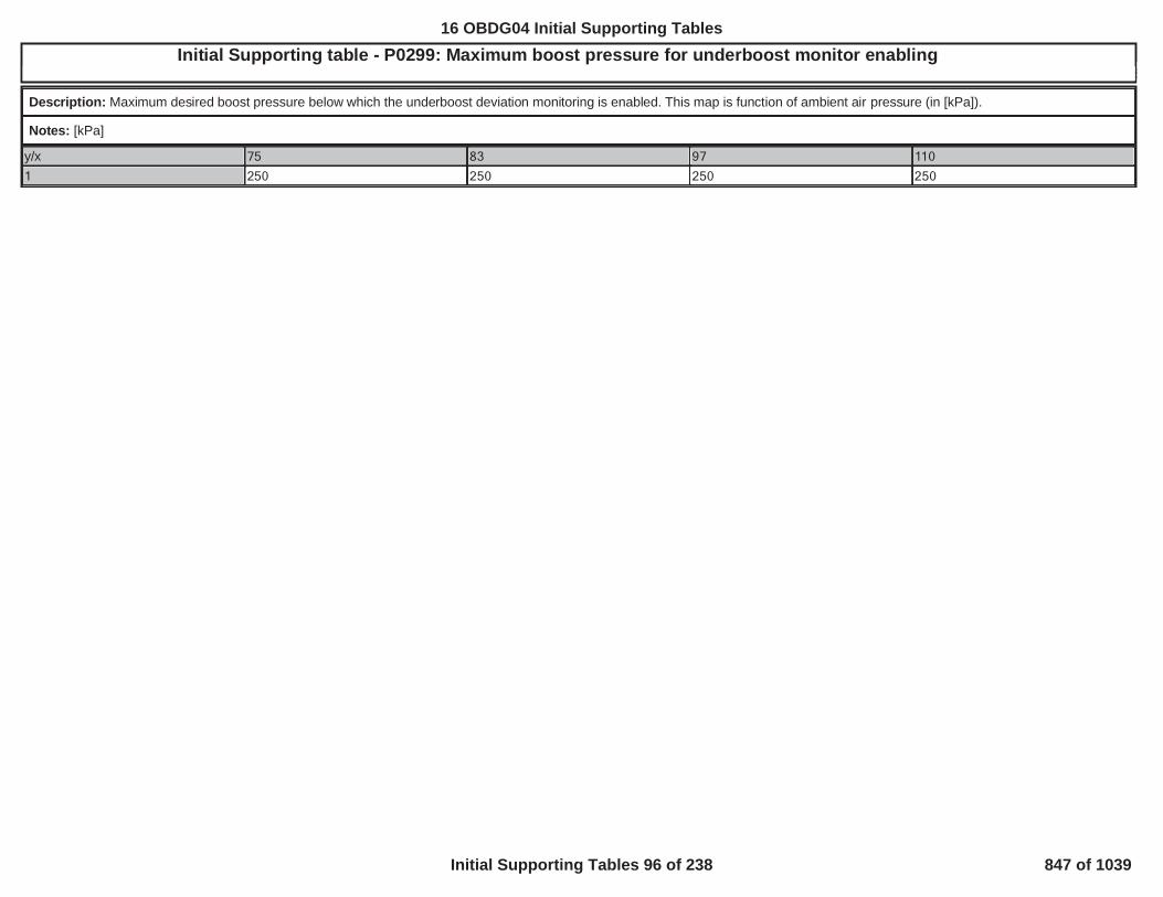
Initial Supporting table - P0299: Maximum boost pressure for underboost monitor enabling5
Description: Maximum desired boost pressure below which the underboost deviation monitoring is enabled. This map is function of ambient air pressure (in [kPa]).
Notes: [kPa]
y/x 75 83 97 110
1 250 250 250 250
848
16 OBDG04 Initial Supporting Tables
Initial Supporting Tables 96 of 238 847 of 1039

Initial Supporting table - P0299: Minimum boost pressure for underboost monitor enabling5
Description: Minimum desired boost pressure above which the underboost deviation monitoring is enabled. This map is function of ambient air pressure (in [kPa]).
Notes: [kPa]
y/x 75 83 97 110
1 170 170 170 170
849
16 OBDG04 Initial Supporting Tables
Initial Supporting Tables 97 of 238 848 of 1039

Initial Supporting table - P0299: Positive boost deviation threshold (throttle control active)5
Description: Boost pressure deviation threshold for the positive boost pressure control deviation monitor when the throttle control is active. It identifies an underboost faulty condition. It isfunction of engine speed (in [rpm]) and desired boost pressure (in [kPa]).
Notes: [kPa]
y/x 85 100 115 130 145 160 175 190 205 220 235 250 265 280 295750 47 47 47 47 47 47 47 47 47 47 47 47 47 37 371,000 42 42 42 42 42 42 42 42 42 42 42 42 42 42 421,250 42 42 37 37 37 37 37 37 37 32 32 32 32 32 321,500 42 42 37 37 37 37 37 37 37 32 32 32 32 32 321,750 42 42 37 37 37 37 37 37 37 30 30 30 30 30 302,000 42 42 37 37 32 32 30 30 30 30 30 30 30 30 302,250 42 42 37 37 32 32 30 30 30 30 30 30 30 30 302,500 42 42 37 37 32 32 30 30 30 30 30 30 30 30 303,000 37 37 37 37 37 37 37 37 37 37 37 37 37 47 574,200 47 47 37 37 37 37 37 37 37 37 37 47 57 67 67
850
16 OBDG04 Initial Supporting Tables
Initial Supporting Tables 98 of 238 849 of 1039

Initial Supporting table - P0299: Positive boost deviation threshold (throttle control not active)5
Description: Boost pressure deviation threshold for the positive boost pressure control deviation monitor when the throttle control is not active. It identifies an underboost faulty condition.It is function of engine speed (in [rpm]) and desired boost pressure (in [kPa]).
Notes: [kPa]
y/x 85 100 115 130 145 160 175 190 205 220 235 250 265 280 295750 42 42 42 42 42 42 42 42 42 42 42 42 42 42 421,000 42 42 42 42 42 42 42 42 42 42 42 42 42 42 421,250 42 42 37 37 37 37 37 37 37 32 32 32 32 32 321,500 42 42 37 37 37 37 37 37 37 32 32 32 32 32 321,750 42 42 37 37 37 37 37 37 37 30 30 30 30 30 302,000 42 42 37 37 32 32 30 30 30 30 30 30 30 30 302,250 42 42 37 37 32 32 30 30 30 30 30 30 30 30 302,500 42 42 37 37 32 32 30 30 30 30 30 30 30 30 303,000 42 42 37 37 32 32 32 32 32 32 32 32 32 32 324,200 42 42 37 37 35 35 35 35 35 35 35 35 35 35 35
851
16 OBDG04 Initial Supporting Tables
Initial Supporting Tables 99 of 238 850 of 1039

Initial Supporting table - P0299: Underboost monitor delay timer5
Description: Delay timer before enabling the underboost deviation monitoring once all entry conditions are fulfilled. This map is function of engine speed (in [rpm]).
Notes: [s]
y/x 750 1,000 1,250 1,500 1,750 2,000 2,250 2,500 3,000 4,200
1 2 2 2 2 2 2 2 2 2 2
852
16 OBDG04 Initial Supporting Tables
Initial Supporting Tables 100 of 238 851 of 1039

Initial Supporting table - P0400: EGR flow performance threshold (air flow tracking error)5
Description: Air mass flow threshold for OBDII EGR flow performance monitor when EGR controller is tracking a flow error. It is function of engine speed (in [rpm]) and total EGR flowrequest (in [mg]).
Notes: [mg]
y/x 1 2 3 4 5 6 7 8 9 10 11 12 13 14 15 161 1,000 1,000 1,000 1,000 1,000 1,000 1,000 1,000 1,000 1,000 1,000 1,000 1,000 1,000 1,000 1,0002 1,000 1,000 1,000 1,000 1,000 1,000 1,000 1,000 1,000 1,000 1,000 1,000 1,000 1,000 1,000 1,0003 1,000 1,000 1,000 1,000 1,000 1,000 1,000 1,000 1,000 1,000 1,000 1,000 1,000 1,000 1,000 1,0004 1,000 1,000 1,000 1,000 1,000 1,000 1,000 1,000 1,000 1,000 1,000 1,000 1,000 1,000 1,000 1,0005 1,000 1,000 1,000 1,000 1,000 1,000 1,000 1,000 1,000 1,000 1,000 1,000 1,000 1,000 1,000 1,0006 1,000 1,000 1,000 1,000 1,000 1,000 1,000 1,000 1,000 1,000 1,000 1,000 1,000 1,000 1,000 1,0007 1,000 1,000 1,000 1,000 1,000 1,000 1,000 1,000 1,000 1,000 1,000 1,000 1,000 1,000 1,000 1,0008 1,000 1,000 1,000 1,000 1,000 1,000 1,000 1,000 1,000 1,000 1,000 1,000 1,000 1,000 1,000 1,0009 1,000 1,000 1,000 1,000 1,000 1,000 1,000 1,000 1,000 1,000 1,000 1,000 1,000 1,000 1,000 1,00010 1,000 1,000 1,000 1,000 1,000 1,000 1,000 1,000 1,000 1,000 1,000 1,000 1,000 1,000 1,000 1,00011 1,000 1,000 1,000 1,000 1,000 1,000 1,000 1,000 1,000 1,000 1,000 1,000 1,000 1,000 1,000 1,00012 1,000 1,000 1,000 1,000 1,000 1,000 1,000 1,000 1,000 1,000 1,000 1,000 1,000 1,000 1,000 1,00013 1,000 1,000 1,000 1,000 1,000 1,000 1,000 1,000 1,000 1,000 1,000 1,000 1,000 1,000 1,000 1,00014 1,000 1,000 1,000 1,000 1,000 1,000 1,000 1,000 1,000 1,000 1,000 1,000 1,000 1,000 1,000 1,00015 1,000 1,000 1,000 1,000 1,000 1,000 1,000 1,000 1,000 1,000 1,000 1,000 1,000 1,000 1,000 1,000
853
16 OBDG04 Initial Supporting Tables
Initial Supporting Tables 101 of 238 852 of 1039

Initial Supporting table - P0400: EGR flow performance threshold (air mass tracking error)5
Description: Air mass flow threshold for OBDII EGR flow performance monitor when EGR controller is tracking a fresh air mass error. It is function of engine speed (in [rpm]) and desiredfresh air mass (in [mg]).
Notes: [mg]
y/x 1 2 3 4 5 6 7 8 9 10 11 12 13 14 15 161 1,000 1,000 1,000 1,000 1,000 1,000 1,000 1,000 1,000 1,000 1,000 1,000 1,000 1,000 1,000 1,0002 1,000 1,000 1,000 1,000 1,000 1,000 1,000 1,000 1,000 1,000 1,000 1,000 1,000 1,000 1,000 1,0003 1,000 1,000 1,000 1,000 1,000 1,000 1,000 1,000 1,000 1,000 1,000 1,000 1,000 1,000 1,000 1,0004 1,000 1,000 1,000 1,000 1,000 1,000 1,000 1,000 1,000 1,000 1,000 1,000 1,000 1,000 1,000 1,0005 1,000 1,000 1,000 1,000 1,000 1,000 1,000 1,000 1,000 1,000 1,000 1,000 1,000 1,000 1,000 1,0006 1,000 1,000 1,000 1,000 1,000 1,000 1,000 1,000 1,000 1,000 1,000 1,000 1,000 1,000 1,000 1,0007 1,000 1,000 1,000 1,000 1,000 1,000 1,000 1,000 1,000 1,000 1,000 1,000 1,000 1,000 1,000 1,0008 1,000 1,000 1,000 1,000 1,000 1,000 1,000 1,000 1,000 1,000 1,000 1,000 1,000 1,000 1,000 1,0009 1,000 1,000 1,000 1,000 1,000 1,000 1,000 1,000 1,000 1,000 1,000 1,000 1,000 1,000 1,000 1,00010 1,000 1,000 1,000 1,000 1,000 1,000 1,000 1,000 1,000 1,000 1,000 1,000 1,000 1,000 1,000 1,00011 1,000 1,000 1,000 1,000 1,000 1,000 1,000 1,000 1,000 1,000 1,000 1,000 1,000 1,000 1,000 1,00012 1,000 1,000 1,000 1,000 1,000 1,000 1,000 1,000 1,000 1,000 1,000 1,000 1,000 1,000 1,000 1,00013 1,000 1,000 1,000 1,000 1,000 1,000 1,000 1,000 1,000 1,000 1,000 1,000 1,000 1,000 1,000 1,00014 1,000 1,000 1,000 1,000 1,000 1,000 1,000 1,000 1,000 1,000 1,000 1,000 1,000 1,000 1,000 1,00015 1,000 1,000 1,000 1,000 1,000 1,000 1,000 1,000 1,000 1,000 1,000 1,000 1,000 1,000 1,000 1,000
854
16 OBDG04 Initial Supporting Tables
Initial Supporting Tables 102 of 238 853 of 1039

Initial Supporting table - P0401, P0402: EGR flow monitor enabling5
Description: Calibration map to choose if the excessive/insufficient EGR flow monitor is enabled or not for each combustion mode.
Notes: [boolean]
P0401, P0402: EGR flow monitor enabling - Part 1
y/x CeCMBR_e_Normal CeCMBR_e_DPF_HiO2 CeCMBR_e_DPF_LoO2 CeCMBR_e_C2 CeCMBR_e_LNT_DeNOx CeCMBR_e_LNT_DeSOx_Lean
1 1 0 0 0 0 0
P0401, P0402: EGR flow monitor enabling - Part 2
y/x CeCMBR_e_LNT_DeSOx_Rich
CeCMBR_e_C3 CeCMBR_e_SCR_Temp1 CeCMBR_e_SCR_Temp2 CeCMBR_e_DPF_PN CeCMBR_e_DPF_RichIdle
1 0 0 0 0 0 0
P0401, P0402: EGR flow monitor enabling - Part 3
y/x CeCMBR_e_DPF_EngPrtct_HiO2
CeCMBR_e_DPF_EngPrtct_LoO2
CeCMBR_e_LNT_EngPrtct
CeCMBR_e_SCR_Temp3 CeCMBR_e_FAD_IdleInjLrn
CeCMBR_e_HCS_DeHC_Drive
1 0 0 0 0 0 0
P0401, P0402: EGR flow monitor enabling - Part 4
y/x CeCMBR_e_HCS_DeHC_Park
CeCMBR_e_SCR_ServWarmUp
CeCMBR_e_SCR_ServCheck
CeCMBR_e_SCR_DeSOx
1 0 0 0 0
855
16 OBDG04 Initial Supporting Tables
Initial Supporting Tables 103 of 238 854 of 1039

Initial Supporting table - P0401: Insufficient EGR flow barometric correction (low level)5
Description: Air Temperature correction at low barometric level for OBDII insufficient EGR flow monitor. It is function of air temperature (in [°C]).
Notes: [-1, 1]
y/x -7 -5 0 5 10 15 20 25 30 35
1 1 1 1 1 1 1 1 1 1 1
856
16 OBDG04 Initial Supporting Tables
Initial Supporting Tables 104 of 238 855 of 1039

Initial Supporting table - P0401: Insufficient EGR flow barometric correction (mid level)5
Description: Air Temperature correction at mid barometric level for OBDII insufficient EGR flow monitor. It is function of air temperature (in [°C]).
Notes: [-1, 1]
y/x -7 -5 0 5 10 15 20 25 30 35
1 1 1 1 1 1 1 1 1 1 1
857
16 OBDG04 Initial Supporting Tables
Initial Supporting Tables 105 of 238 856 of 1039

Initial Supporting table - P0401: Insufficient EGR flow barometric correction (sea level)5
Description: Air Temperature correction at sea barometric level for OBDII insufficient EGR flow monitor. It is function of air temperature (in [°C]).
Notes: [-1,1]
y/x -7 -5 0 5 10 15 20 25 30 35
1 1 1 1 1 1 1 1 1 1 1
858
16 OBDG04 Initial Supporting Tables
Initial Supporting Tables 106 of 238 857 of 1039

Initial Supporting table - P0401: Insufficient EGR flow barometric table A (low level)5
Description: Barometric (low level) calibration table for defining a OBDII threshold for insufficient EGR flow deviation monitoring. It is function of engine speed (in [rpm]) and load (in[composite]), which can be either fuel air request or predicted torque request.
Notes: [mg]
y/x 730 1,250 1,500 1,750 2,000 2,500 3,000 4,200
0 0 0 0 0 0 0 0 0
5 0 0 0 0 0 0 0 0
15 0 0 0 0 0 0 0 0
25 0 0 0 0 0 0 0 0
30 0 0 0 0 0 0 0 0
45 0 0 0 0 0 0 0 0
50 0 0 0 0 0 0 0 0
55 0 0 0 0 0 0 0 0
60 0 0 0 0 0 0 0 0
859
16 OBDG04 Initial Supporting Tables
Initial Supporting Tables 107 of 238 858 of 1039

Initial Supporting table - P0401: Insufficient EGR flow barometric table A (mid level)5
Description: Barometric (mid level) calibration table for defining a OBDII threshold for insufficient EGR flow deviation monitoring. It is function of engine speed (in [rpm]) and load (in[composite]), which can be either fuel air request or predicted torque request.
Notes: [mg]
y/x 730 1,250 1,500 1,750 2,000 2,500 3,000 4,200
0 0 0 0 0 0 0 0 0
5 0 0 0 0 0 0 0 0
15 0 0 0 0 0 0 0 0
25 0 0 0 0 0 0 0 0
30 0 0 0 0 0 0 0 0
45 0 0 0 0 0 0 0 0
50 0 0 0 0 0 0 0 0
55 0 0 0 0 0 0 0 0
60 0 0 0 0 0 0 0 0
860
16 OBDG04 Initial Supporting Tables
Initial Supporting Tables 108 of 238 859 of 1039

Initial Supporting table - P0401: Insufficient EGR flow barometric table A (sea level)5
Description: Barometric (sea level) calibration table for defining a OBDII threshold for insufficient EGR flow deviation monitoring. It is function of engine speed (in [rpm]) and load (in[composite]), which can be either fuel air request or predicted torque request.
Notes: [mg]
y/x 730 1,250 1,500 1,750 2,000 2,500 3,000 4,200
0 0 0 0 0 0 0 0 0
5 0 0 0 0 0 0 0 0
15 0 0 0 0 0 0 0 0
25 0 0 0 0 0 0 0 0
30 0 0 0 0 0 0 0 0
45 0 0 0 0 0 0 0 0
50 0 0 0 0 0 0 0 0
55 0 0 0 0 0 0 0 0
60 0 0 0 0 0 0 0 0
861
16 OBDG04 Initial Supporting Tables
Initial Supporting Tables 109 of 238 860 of 1039

Initial Supporting table - P0401: Insufficient EGR flow barometric table B (low level)5
Description: Barometric (low level) calibration table for defining a OBDII threshold for insufficient EGR flow deviation monitoring. It is function of engine speed (in [rpm]) and load (in[composite]), which can be either fuel air request or predicted torque request.
Notes: [mg]
y/x 730 1,250 1,500 1,750 2,000 2,500 3,000 4,2000 -120 -120 -504 -504 -504 -504 -504 -5045 -160 -64 -64 -64 -64 -504 -504 -50415 -208 -64 -64 -64 -64 -504 -504 -50425 -248 -64 -64 -64 -64 -504 -504 -50430 -264 -64 -64 -64 -64 -504 -504 -50445 -296 -192 -152 -224 -504 -504 -504 -50450 -368 -208 -184 -152 -504 -504 -504 -50455 -432 -368 -368 -368 -504 -504 -504 -50460 -504 -504 -504 -504 -504 -504 -504 -504
862
16 OBDG04 Initial Supporting Tables
Initial Supporting Tables 110 of 238 861 of 1039

Initial Supporting table - P0401: Insufficient EGR flow barometric table B (mid level)5
Description: Barometric (mid level) calibration table for defining a OBDII threshold for insufficient EGR flow deviation monitoring. It is function of engine speed (in [rpm]) and load (in[composite]), which can be either fuel air request or predicted torque request.
Notes: [mg]
y/x 730 1,250 1,500 1,750 2,000 2,500 3,000 4,2000 -120 -120 -504 -504 -504 -504 -504 -5045 -160 -152 -152 -152 -152 -504 -504 -50415 -208 -152 -152 -152 -152 -504 -504 -50425 -248 -152 -152 -152 -152 -504 -504 -50430 -264 -224 -224 -200 -200 -504 -504 -50445 -296 -192 -152 -224 -504 -504 -504 -50450 -368 -208 -184 -152 -504 -504 -504 -50455 -432 -368 -368 -368 -504 -504 -504 -50460 -504 -504 -504 -504 -504 -504 -504 -504
863
16 OBDG04 Initial Supporting Tables
Initial Supporting Tables 111 of 238 862 of 1039

Initial Supporting table - P0401: Insufficient EGR flow barometric table B (sea level)5
Description: Barometric (sea level) calibration table for defining a OBDII threshold for insufficient EGR flow deviation monitoring. It is function of engine speed (in [rpm]) and load (in[composite]), which can be either fuel air request or predicted torque request.
Notes: [mg]
y/x 730 1,250 1,500 1,750 2,000 2,500 3,000 4,2000 -120 -120 -504 -504 -504 -504 -504 -5045 -160 -144 -152 -152 -200 -504 -504 -50415 -208 -152 -152 -152 -200 -504 -504 -50425 -248 -200 -176 -176 -200 -504 -504 -50430 -264 -224 -224 -200 -200 -504 -504 -50445 -296 -192 -152 -224 -504 -504 -504 -50450 -368 -208 -184 -152 -504 -504 -504 -50455 -432 -368 -368 -368 -504 -504 -504 -50460 -504 -504 -504 -504 -504 -504 -504 -504
864
16 OBDG04 Initial Supporting Tables
Initial Supporting Tables 112 of 238 863 of 1039

Initial Supporting table - P0401: Minimum desired EGR flow5
Description: Minimum desired EGR flow above which the insufficient EGR flow is enabled. It is function of barometric pressure (in [kPa]).
Notes: [mg]
y/x 70 74 81 100
1 252 252 276 300
865
16 OBDG04 Initial Supporting Tables
Initial Supporting Tables 113 of 238 864 of 1039

Initial Supporting table - P0402: Excessive EGR flow barometric correction (low level)5
Description: Air Temperature correction at low barometric level for OBDII excessive EGR flow monitor. It is function of air temperature (in [°C]).
Notes: [-1, 1]
y/x -7 -5 0 5 10 15 20 25 30 35
1 0 0 0 0 0 0 0 0 0 0
866
16 OBDG04 Initial Supporting Tables
Initial Supporting Tables 114 of 238 865 of 1039

Initial Supporting table - P0402: Excessive EGR flow barometric correction (mid level)5
Description: Air Temperature correction at mid barometric level for OBDII excessive EGR flow monitor. It is function of air temperature (in [°C]).
Notes: [-1, 1]
y/x -7 -5 0 5 10 15 20 25 30 35
1 0 0 0 0 0 0 0 0 0 0
867
16 OBDG04 Initial Supporting Tables
Initial Supporting Tables 115 of 238 866 of 1039

Initial Supporting table - P0402: Excessive EGR flow barometric correction (sea level)5
Description: Air Temperature correction at sea barometric level for OBDII excessive EGR flow monitor. It is function of air temperature (in [°C]).
Notes: [-1, 1]
y/x -7 -5 0 5 10 15 20 25 30 35
1 0 0 0 0 0 0 0 0 0 0
868
16 OBDG04 Initial Supporting Tables
Initial Supporting Tables 116 of 238 867 of 1039

Initial Supporting table - P0402: Excessive EGR flow barometric table A (low level)5
Description: Barometric (low level) calibration table for defining a OBDII threshold for excessive EGR flow deviation monitoring. It is function of engine speed (in [rpm]) and load (in[composite]), which can be either fuel air request or predicted torque request.
Notes: [mg]
y/x 600 1,000 1,500 1,750 2,000 2,500 3,000 4,200
0 0 0 0 0 0 0 0 0
10 0 0 0 0 0 0 0 0
20 0 0 0 0 0 0 0 0
35 0 0 0 0 0 0 0 0
45 0 0 0 0 0 0 0 0
65 0 0 0 0 0 0 0 0
80 0 0 0 0 0 0 0 0
100 0 0 0 0 0 0 0 0
120 0 0 0 0 0 0 0 0
869
16 OBDG04 Initial Supporting Tables
Initial Supporting Tables 117 of 238 868 of 1039

Initial Supporting table - P0402: Excessive EGR flow barometric table A (mid level)5
Description: Barometric (mid level) calibration table for defining a OBDII threshold for excessive EGR flow deviation monitoring. It is function of engine speed (in [rpm]) and load (in[composite]), which can be either fuel air request or predicted torque request.
Notes: [mg]
y/x 600 1,000 1,500 1,750 2,000 2,500 3,000 4,200
0 0 0 0 0 0 0 0 0
10 0 0 0 0 0 0 0 0
20 0 0 0 0 0 0 0 0
35 0 0 0 0 0 0 0 0
45 0 0 0 0 0 0 0 0
65 0 0 0 0 0 0 0 0
80 0 0 0 0 0 0 0 0
100 0 0 0 0 0 0 0 0
120 0 0 0 0 0 0 0 0
870
16 OBDG04 Initial Supporting Tables
Initial Supporting Tables 118 of 238 869 of 1039

Initial Supporting table - P0402: Excessive EGR flow barometric table A (sea level)5
Description: Barometric (sea level) calibration table for defining a OBDII threshold for excessive EGR flow deviation monitoring. It is function of engine speed (in [rpm]) and load (in[composite]), which can be either fuel air request or predicted torque request.
Notes: [mg]
y/x 600 1,000 1,500 1,750 2,000 2,500 3,000 4,200
0 0 0 0 0 0 0 0 0
10 0 0 0 0 0 0 0 0
20 0 0 0 0 0 0 0 0
35 0 0 0 0 0 0 0 0
45 0 0 0 0 0 0 0 0
65 0 0 0 0 0 0 0 0
80 0 0 0 0 0 0 0 0
100 0 0 0 0 0 0 0 0
120 0 0 0 0 0 0 0 0
871
16 OBDG04 Initial Supporting Tables
Initial Supporting Tables 119 of 238 870 of 1039

Initial Supporting table - P0402: Excessive EGR flow barometric table B (low level)5
Description: Barometric (low level) calibration table for defining a OBDII threshold for excessive EGR flow deviation monitoring. It is function of engine speed (in [rpm]) and load (in[composite]), which can be either fuel air request or predicted torque request.
Notes: [mg]
y/x 600 1,000 1,500 1,750 2,000 2,500 3,000 4,2000 120 120 120 120 120 208 296 50410 120 120 120 120 120 208 296 50420 152 152 152 152 152 232 312 50435 192 352 200 176 192 264 336 50445 224 352 200 176 224 288 352 50465 296 352 200 200 296 344 392 50480 368 368 368 368 368 400 432 504100 432 432 432 432 432 448 464 504120 504 504 504 504 504 504 504 504
872
16 OBDG04 Initial Supporting Tables
Initial Supporting Tables 120 of 238 871 of 1039

Initial Supporting table - P0402: Excessive EGR flow barometric table B (mid level)5
Description: Barometric (mid level) calibration table for defining a OBDII threshold for excessive EGR flow deviation monitoring. It is function of engine speed (in [rpm]) and load (in[composite]), which can be either fuel air request or predicted torque request.
Notes: [mg]
y/x 600 1,000 1,500 1,750 2,000 2,500 3,000 4,2000 120 120 120 120 120 208 296 50410 120 120 120 120 120 208 296 50420 152 152 152 152 152 232 312 50435 192 352 152 152 152 264 336 50445 224 352 144 144 144 288 352 50465 296 352 120 120 120 344 392 50480 368 368 200 200 200 400 432 504100 432 432 432 432 432 448 464 504120 504 504 504 504 504 504 504 504
873
16 OBDG04 Initial Supporting Tables
Initial Supporting Tables 121 of 238 872 of 1039

Initial Supporting table - P0402: Excessive EGR flow barometric table B (sea level)5
Description: Barometric (sea level) calibration table for defining a OBDII threshold for excessive EGR flow deviation monitoring. It is function of engine speed (in [rpm]) and load (in[composite]), which can be either fuel air request or predicted torque request.
Notes: [mg]
y/x 600 1,000 1,500 1,750 2,000 2,500 3,000 4,2000 120 120 120 120 120 208 296 50410 120 120 120 120 120 208 296 50420 152 152 152 152 152 232 312 50435 192 200 152 176 192 264 336 50445 224 200 152 176 192 288 352 50465 296 200 152 176 192 344 392 50480 368 368 368 368 368 400 432 504100 432 432 432 432 432 448 464 504120 504 504 504 504 504 504 504 504
874
16 OBDG04 Initial Supporting Tables
Initial Supporting Tables 122 of 238 873 of 1039

Initial Supporting table - P0402: Maximum desired EGR flow5
Description: Maximum desired EGR flow below which the excessive EGR flow is enabled. It is function of barometric pressure (in [kPa]).
Notes: [mg]
y/x 70 74 81 100
1 252 252 300 352
875
16 OBDG04 Initial Supporting Tables
Initial Supporting Tables 123 of 238 874 of 1039

Initial Supporting table - P140B, P140C: EGR slow response enabling5
Description: Calibration map for the enabling of EGR slow response monitoring, function of combustion mode.
Notes: [boolean]
P140B, P140C: EGR slow response enabling - Part 1
y/x CeCMBR_e_Normal CeCMBR_e_DPF_HiO2 CeCMBR_e_DPF_LoO2 CeCMBR_e_C2 CeCMBR_e_LNT_DeNOx CeCMBR_e_LNT_DeSOx_Lean
1 1 1 0 0 0 0
P140B, P140C: EGR slow response enabling - Part 2
y/x CeCMBR_e_LNT_DeSOx_Rich
CeCMBR_e_C3 CeCMBR_e_SCR_Temp1 CeCMBR_e_SCR_Temp2 CeCMBR_e_DPF_PN CeCMBR_e_DPF_RichIdle
1 0 0 0 0 0 0
P140B, P140C: EGR slow response enabling - Part 3
y/x CeCMBR_e_DPF_EngPrtct_HiO2
CeCMBR_e_DPF_EngPrtct_LoO2
CeCMBR_e_LNT_EngPrtct
CeCMBR_e_SCR_Temp3 CeCMBR_e_FAD_IdleInjLrn
CeCMBR_e_HCS_DeHC_Drive
1 0 0 0 0 0 0
P140B, P140C: EGR slow response enabling - Part 4
y/x CeCMBR_e_HCS_DeHC_Park
CeCMBR_e_SCR_ServWarmUp
CeCMBR_e_SCR_ServCheck
CeCMBR_e_SCR_DeSOx
1 0 0 0 0
876
16 OBDG04 Initial Supporting Tables
Initial Supporting Tables 124 of 238 875 of 1039

Initial Supporting table - P140B: Increasing EGR slow response threshold5
Description: Threshold for increasing EGR flow slow response monitoring. It is function of ambient air pressure (in [kPa]).
Notes: [%]
y/x 75 84 97
1 4 6 10
877
16 OBDG04 Initial Supporting Tables
Initial Supporting Tables 125 of 238 876 of 1039

Initial Supporting table - P140C: Decreasing EGR slow response threshold5
Description: Threshold for decreasing EGR flow slow response monitoring. It is function of ambient air pressure (in [kPa]).
Notes: [%]
y/x 75 84 97
1 3 5 8
878
16 OBDG04 Initial Supporting Tables
Initial Supporting Tables 126 of 238 877 of 1039

Initial Supporting table - P168A, P168B: Boost pressure slow response enabling5
Description: Calibration map for the enabling of boost pressure slow response monitoring, function of combustion mode.
Notes: [boolean]
P168A, P168B: Boost pressure slow response enabling - Part 1
y/x CeCMBR_e_Normal CeCMBR_e_DPF_HiO2 CeCMBR_e_DPF_LoO2 CeCMBR_e_C2 CeCMBR_e_LNT_DeNOx CeCMBR_e_LNT_DeSOx_Lean
1 0 0 0 0 0 0
P168A, P168B: Boost pressure slow response enabling - Part 2
y/x CeCMBR_e_LNT_DeSOx_Rich
CeCMBR_e_C3 CeCMBR_e_SCR_Temp1 CeCMBR_e_SCR_Temp2 CeCMBR_e_DPF_PN CeCMBR_e_DPF_RichIdle
1 0 0 0 0 0 0
P168A, P168B: Boost pressure slow response enabling - Part 3
y/x CeCMBR_e_DPF_EngPrtct_HiO2
CeCMBR_e_DPF_EngPrtct_LoO2
CeCMBR_e_LNT_EngPrtct
CeCMBR_e_SCR_Temp3 CeCMBR_e_FAD_IdleInjLrn
CeCMBR_e_HCS_DeHC_Drive
1 0 0 0 0 0 0
P168A, P168B: Boost pressure slow response enabling - Part 4
y/x CeCMBR_e_HCS_DeHC_Park
CeCMBR_e_SCR_ServWarmUp
CeCMBR_e_SCR_ServCheck
CeCMBR_e_SCR_DeSOx
1 0 0 0 0
16 OBDG04 Initial Supporting Tables
Initial Supporting Tables 127 of 238 878 of 1039

Initial Supporting table - P168A: Positive boost slow response threshold5
Description: Averaged cumulative boost pressure deviation threshold for the positive boost pressure slow response monitor. The map is function of ambient air pressure (in [kPa]).
Notes: [kPa]
y/x 75 83 97
1 29 29 29
880
16 OBDG04 Initial Supporting Tables
Initial Supporting Tables 128 of 238 879 of 1039

Initial Supporting table - P168B: Negative boost slow response threshold5
Description: Averaged cumulative boost pressure deviation threshold for the negative boost pressure slow response monitor. The map is function of ambient air pressure (in [kPa]).
Notes: [kPa]
y/x 75 83 97
1 10 10 10
881
16 OBDG04 Initial Supporting Tables
Initial Supporting Tables 129 of 238 880 of 1039

Initial Supporting table - P16F3_CB safety deadband threshold f(Fuel Rail Pressure)5
Description: Maximum allowable safety deadband on CB Energizing Time compensation (for each torque forming pulse) as a function of Fuel Rail Pressure.
Notes: P16F3, KtETMC_t_CB_ET_Max
y/x 16 28 39 51 62 74 85 97 108 120 131 143 154 166 177 189 2001 1,633 738 535 425 361 320 292 268 251 237 223 211 201 194 186 177 170
882
16 OBDG04 Initial Supporting Tables
Initial Supporting Tables 130 of 238 881 of 1039
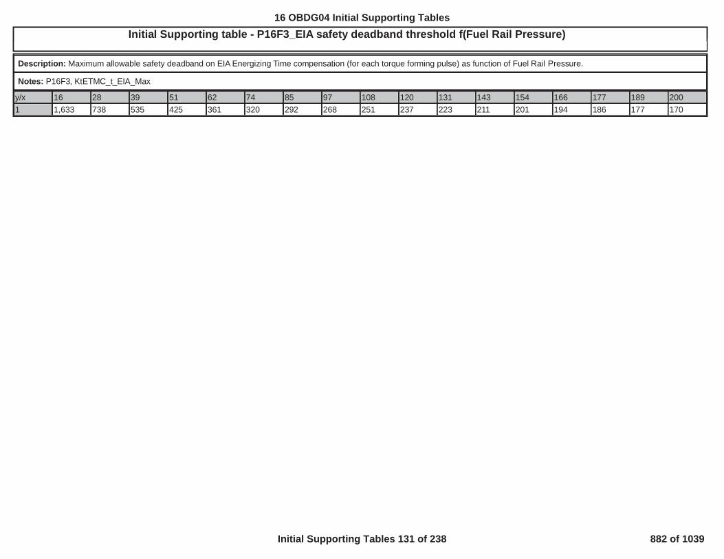
Initial Supporting table - P16F3_EIA safety deadband threshold f(Fuel Rail Pressure)5
Description: Maximum allowable safety deadband on EIA Energizing Time compensation (for each torque forming pulse) as function of Fuel Rail Pressure.
Notes: P16F3, KtETMC_t_EIA_Max
y/x 16 28 39 51 62 74 85 97 108 120 131 143 154 166 177 189 2001 1,633 738 535 425 361 320 292 268 251 237 223 211 201 194 186 177 170
883
16 OBDG04 Initial Supporting Tables
Initial Supporting Tables 131 of 238 882 of 1039

Initial Supporting table - P16F3_FTD safety deadband threshold f(Fuel Rail Pressure)5
Description: Maximum allowable safety deadband on FTD Energizing Time compensation as function of Fuel Rail Pressure.
Notes: P16F3, KtETMC_t_FTD_Max
y/x 16 28 39 51 62 74 85 97 108 120 131 143 154 166 177 189 2001 1,633 738 535 425 361 320 292 268 251 237 223 211 201 194 186 177 170
884
16 OBDG04 Initial Supporting Tables
Initial Supporting Tables 132 of 238 883 of 1039

Initial Supporting table - P16F3_Rail Pressure Wave Compensation f(Fuel Rail Pressure, Fuel Quantity)5
Description: Safety treshold for the Rail Pressure Wave Compensation on each torque forming pulse as a function of Fuel Rail Pressure and Fuel Quantity
Notes: P16F3, KtFULC_p_RPWC_RailPosDeltSfty
y/x 0 1 2 3 5 7 10 15 25 35 40 50
20 1 1 1 1 1 1 1 1 1 1 1 1
40 1 1 1 1 1 1 1 1 1 1 1 1
60 1 1 1 1 1 1 1 1 1 1 1 1
80 1 1 1 1 1 1 1 1 1 1 1 1
100 1 1 1 1 1 1 1 1 1 1 1 1
120 1 1 1 1 1 1 1 1 1 1 1 1
140 1 1 1 1 1 1 1 1 1 1 1 1
160 1 1 1 1 1 1 1 1 1 1 1 1
180 1 1 1 1 1 1 1 1 1 1 1 1
200 1 1 1 1 1 1 1 1 1 1 1 1
885
16 OBDG04 Initial Supporting Tables
Initial Supporting Tables 133 of 238 884 of 1039

Initial Supporting table - P16F3_Speed Control External Load f(Oil Temp, RPM)5
Description: Specifies the external load table for SPDR torque security as a function of engine oil temperature and engine RPM.
Notes: P16F3, KtSPDC_M_ExternalLoad
y/x -40 -20 -10 0 50 90530 358 315 290 264 222 215630 358 315 290 254 212 205730 355 312 287 240 193 186750 353 310 285 235 189 182800 348 305 280 222 180 173900 338 295 272 197 157 1501,000 321 287 268 187 147 1401,100 288 255 237 190 150 1441,200 258 225 208 192 153 1481,400 258 225 208 192 153 1481,600 169 136 119 103 64 592,000 -81 -85 -89 -92 -105 -1102,500 -89 -94 -98 -101 -115 -1213,000 -97 -102 -107 -110 -126 -1323,500 -105 -111 -116 -120 -136 -1434,000 -113 -119 -125 -129 -147 -1545,000 -113 -119 -125 -129 -147 -154
886
16 OBDG04 Initial Supporting Tables
Initial Supporting Tables 134 of 238 885 of 1039

Initial Supporting table - P16F3_SQA safety deadband threshold f(Fuel Rail Pressure)5
Description: Maximum allowable safety deadband on SQA Energizing Time compensation (for each torque forming pulse) as function of Fuel Rail Pressure.
Notes: P16F3, KtETMC_t_SQA_Max
y/x 16 33 49 66 83 100 116 133 150 167 183 2001 2,467 776 556 451 384 344 307 280 262 245 228 219
887
16 OBDG04 Initial Supporting Tables
Initial Supporting Tables 135 of 238 886 of 1039

Initial Supporting table - P16F3_TSC safety deadband threshold f(Fuel Rail Pressure)5
Description: Maximum allowable safety deadband on Energizing Time compensation for Temperature Specific Current (TSC) (for each torque forming pulse) as function of Fuel RailPressure
Notes: P16F3, KtETMC_t_TSC_Max
y/x 16 28 39 51 62 74 85 97 108 120 131 143 154 166 177 189 2001 1,633 738 535 425 361 320 292 268 251 237 223 211 201 194 186 177 170
888
16 OBDG04 Initial Supporting Tables
Initial Supporting Tables 136 of 238 887 of 1039

Initial Supporting table - P16F3_VCA safety max deadband threshold f(Fuel Rail Pressure)5
Description: Maximum allowable safety deadband on VCA energizing time correction as function of Fuel Rail Pressure.
Notes: P16F3, KtETMC_t_VCA_Max
y/x 16 28 39 51 62 74 85 97 108 120 131 143 154 166 177 189 2001 816 369 267 213 181 160 146 134 125 118 111 106 101 97 93 89 85
889
16 OBDG04 Initial Supporting Tables
Initial Supporting Tables 137 of 238 888 of 1039

Initial Supporting table - P16F3_VCA safety min deadband threshold f(Fuel Rail Pressure)5
Description: Minimum allowable safety deadband on VCA energizing time correction as function of Fuel Rail Pressure.
Notes: P16F3, KtETMC_t_VCA_Min
y/x 16 28 39 51 62 74 85 97 108 120 131 143 154 166 177 189 2001 -816 -369 -267 -213 -181 -160 -146 -134 -125 -118 -111 -106 -101 -97 -93 -89 -85
890
16 OBDG04 Initial Supporting Tables
Initial Supporting Tables 138 of 238 889 of 1039

Initial Supporting table - P2160 range change delay time5
Description: Delay time when a transmission range change or transfer case range change occures before the fail time can update. Thresholds are a function of transmission fliudtemperature. Table axis is transmission fliud temperature (DegC) and table output is delay time (seconds).
Notes:
y/x -40.00 0.00 40.00
1 5.00 5.00 5.00
891
16 OBDG04 Initial Supporting Tables
Initial Supporting Tables 139 of 238 890 of 1039

Initial Supporting table - P2161 range change delay time5
Description: Delay time when a transmission range change or transfer case range change occures before the fail time can update. Thresholds are a function of transmission fliudtemperature. Table axis is transmission fliud temperature (DegC) and table output is delay time (seconds).
Notes:
y/x -40.00 -20.00 40.00
1 5.00 5.00 5.00
892
16 OBDG04 Initial Supporting Tables
Initial Supporting Tables 140 of 238 891 of 1039

Initial Supporting table - P2263: Boost pressure system performance high threshold (throttle control active)5
Description: Boost pressure deviation threshold for boost pressure system performance monitor when the throttle control is active. It identifies an overboost faulty condition. It is function ofengine speed (in [rpm]) and desired boost pressure (in [kPa]).
Notes: [kPa]
y/x 100 150 175 200 225 250 275 300
1,500 -30 -30 -30 -25 -25 -25 -25 -25
2,000 -30 -30 -30 -25 -25 -25 -25 -25
2,500 -30 -30 -30 -25 -25 -25 -25 -25
3,000 -30 -30 -30 -25 -25 -25 -25 -25
3,500 -30 -30 -30 -25 -25 -25 -25 -25
4,000 -30 -30 -30 -25 -25 -25 -25 -25
4,500 -30 -30 -30 -25 -25 -25 -25 -25
893
16 OBDG04 Initial Supporting Tables
Initial Supporting Tables 141 of 238 892 of 1039

Initial Supporting table - P2263: Boost pressure system performance high threshold (throttle control not active)5
Description: Boost pressure deviation threshold for boost pressure system performance monitor when the throttle control is not active. It identifies an overboost faulty condition. It isfunction of engine speed (in [rpm]) and desired boost pressure (in [kPa]).
Notes: [kPa]
y/x 100 150 175 200 225 250 275 300
1,500 -40 -40 -40 -35 -35 -35 -35 -35
2,000 -40 -40 -40 -35 -35 -35 -35 -35
2,500 -40 -40 -40 -35 -35 -35 -35 -35
3,000 -40 -40 -40 -35 -35 -35 -35 -35
3,500 -40 -40 -40 -35 -35 -35 -35 -35
4,000 -40 -40 -40 -35 -35 -35 -35 -35
4,500 -40 -40 -40 -35 -35 -35 -35 -35
894
16 OBDG04 Initial Supporting Tables
Initial Supporting Tables 142 of 238 893 of 1039

Initial Supporting table - P2263: Boost pressure system performance low threshold (throttle control active)5
Description: Boost pressure deviation threshold for boost pressure system performance monitor when the throttle control is not active. It identifies an underboost faulty condition. It isfunction of engine speed (in [rpm]) and desired boost pressure (in [kPa]).
Notes: [kPa]
y/x 100 150 175 200 225 250 275 300
1,500 30 30 30 25 25 25 25 25
2,000 30 30 30 25 25 25 25 25
2,500 30 30 30 25 25 25 25 25
3,000 30 30 30 25 25 25 25 25
3,500 30 30 30 25 25 25 25 25
4,000 30 30 30 25 25 25 25 25
4,500 30 30 30 25 25 25 25 25
895
16 OBDG04 Initial Supporting Tables
Initial Supporting Tables 143 of 238 894 of 1039

Initial Supporting table - P2263: Boost pressure system performance low threshold (throttle control not active)5
Description: Boost pressure deviation threshold for boost pressure system performance monitor when the throttle control is not active. It identifies an underboost faulty condition. It isfunction of engine speed (in [rpm]) and desired boost pressure (in [kPa]).
Notes: [kPa]
y/x 100 150 175 200 225 250 275 300
1,500 40 40 40 35 35 35 35 35
2,000 40 40 40 35 35 35 35 35
2,500 40 40 40 35 35 35 35 35
3,000 40 40 40 35 35 35 35 35
3,500 40 40 40 35 35 35 35 35
4,000 40 40 40 35 35 35 35 35
4,500 40 40 40 35 35 35 35 35
896
16 OBDG04 Initial Supporting Tables
Initial Supporting Tables 144 of 238 895 of 1039

Initial Supporting table - P2263: Boost pressure system performance monitor delay timer5
Description: Delay timer before enabling the boost pressure system performance monitor once all entry conditions are fulfilled. This map is function of engine speed (in [rpm]).
Notes: [s]
y/x 1,500 2,000 2,500 3,000 3,500 4,000 4,500
1 2 2 1 1 1 1 1
16 OBDG04 Initial Supporting Tables
Initial Supporting Tables 145 of 238 896 of 1039

Initial Supporting table - P228B Pressure Regulator completely closed command5
Description: Command, in terms of pressure (MPa), to consider pressure regulator valve completely closed as function of rail pressure (MPa).
Notes:
y/x 0 100 190 250
1 30 30 30 30
898
16 OBDG04 Initial Supporting Tables
Initial Supporting Tables 146 of 238 897 of 1039

Initial Supporting table - P228C P228D Air ambient pressure calibrated as enabling condition (MU)5
Description: 0 = air ambient pressure is not considered as enabling condition, 1 = air ambient pressure is considered as enabling condition
Notes:
y/x 1
1 1
899
16 OBDG04 Initial Supporting Tables
Initial Supporting Tables 147 of 238 898 of 1039

Initial Supporting table - P228C P228D Air ambient temperature calibrated as enabling condition (MU)5
Description: 0 = air ambient temperature is not considered as enabling condition, 1 = air ambient temperature is considered as enabling condition
Notes:
y/x 1
1 1
900
16 OBDG04 Initial Supporting Tables
Initial Supporting Tables 148 of 238 899 of 1039

Initial Supporting table - P228C P228D Low fuel level calibrated as enabling condition (MU)5
Description: 0 = low fuel level is not considered as enabling condition, 1 = low fuel level is considered as enabling condition
Notes:
y/x 1
1 1
901
16 OBDG04 Initial Supporting Tables
Initial Supporting Tables 149 of 238 900 of 1039

Initial Supporting table - P228C Positive rail pressure deviation (MU)5
Description: Positive rail pressure deviation threshold (MPa) when metering unit is controlled in closed loop as function of engine speed (rpm).
Notes:
y/x 199 510 511 800 1,000 1,200 1,400 1,600 2,000 2,400 2,800 3,200 3,600 4,200 4,800 5,400
1 80 80 15 15 15 15 15 15 15 15 15 15 15 15 15 15
902
16 OBDG04 Initial Supporting Tables
Initial Supporting Tables 150 of 238 901 of 1039

Initial Supporting table - P228D Negative rail pressure deviation (MU)5
Description: Negative rail pressure deviation threshold (MPa) when metering unit is controlled in closed loop as function of engine speed (rpm).
Notes:
y/x 199 510 511 800 1,000 1,200 1,400 1,600 2,000 2,400 2,800 3,200 3,600 4,200 4,800 5,400
1 -80 -80 -15 -15 -15 -15 -15 -15 -15 -15 -15 -15 -15 -15 -15 -15
903
16 OBDG04 Initial Supporting Tables
Initial Supporting Tables 151 of 238 902 of 1039

Initial Supporting table - P2293 Maximum rail pressure with PR5
Description: Maximum rail pressure threshold (MPa) when pressure is governed by Pressure Regulator as function of engine speed (rpm).
Notes:
y/x 0 1,500 4,250 5,250
1 67 217 217 117
904
16 OBDG04 Initial Supporting Tables
Initial Supporting Tables 152 of 238 903 of 1039

Initial Supporting table - P229A P229B Air ambient pressure calibrated as enabling condition (PR)5
Description: 0 = air ambient pressure is not considered as enabling condition, 1 = air ambient pressure is considered as enabling condition
Notes:
y/x 1
1 1
905
16 OBDG04 Initial Supporting Tables
Initial Supporting Tables 153 of 238 904 of 1039
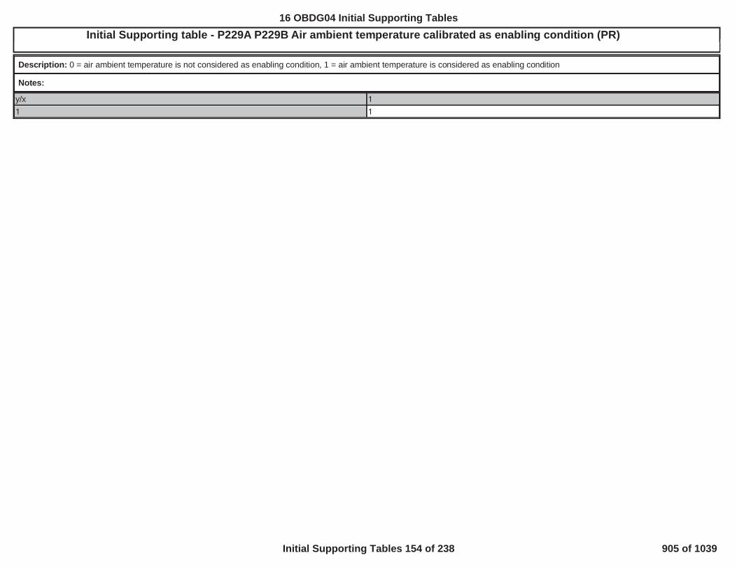
Initial Supporting table - P229A P229B Air ambient temperature calibrated as enabling condition (PR)5
Description: 0 = air ambient temperature is not considered as enabling condition, 1 = air ambient temperature is considered as enabling condition
Notes:
y/x 1
1 1
906
16 OBDG04 Initial Supporting Tables
Initial Supporting Tables 154 of 238 905 of 1039

Initial Supporting table - P229A P229B Low fuel level calibrated as enabling condition (PR)5
Description: 0 = low fuel level is not considered as enabling condition, 1 = low fuel level is considered as enabling condition
Notes:
y/x 1
1 1
907
16 OBDG04 Initial Supporting Tables
Initial Supporting Tables 155 of 238 906 of 1039

Initial Supporting table - P229A Positive rail pressure deviation (PR)5
Description: Positive rail pressure deviation threshold (MPa) when pressure regulator is controlled in closed loop as function of engine speed (rpm).
Notes:
y/x 199 510 511 800 1,000 1,200 1,400 1,600 2,000 2,400 2,800 3,200 3,600 4,200 4,800 5,400
1 80 80 15 15 15 15 15 15 15 15 15 15 15 15 15 15
908
16 OBDG04 Initial Supporting Tables
Initial Supporting Tables 156 of 238 907 of 1039

Initial Supporting table - P24A5: Gradient Temperature Threshold5
Description: EGR Cooler Bypass Stuck diagnosis gradient temperature threshold map to be applied at EGR Cooler Bypass Stuck diagnosis. It is function of the EGR valve total flow (in [g/s])
Notes: [°C]
y/x 0 1 2 3 4 6 8 10
1 0 0 1 1 2 2 2 2
909
16 OBDG04 Initial Supporting Tables
Initial Supporting Tables 157 of 238 908 of 1039

Initial Supporting table - P2598: Positive Position Tracking Error Threshold5
Description: Position tracking error above which the VGT vanes positive position control deviation can detect the vanes stuck in a position more closed than its target position. It is functionof ambient pressure (in [kPa]).
Notes: [%]
y/x 60 70 80 90 100 110
1 15 15 15 15 15 15
910
16 OBDG04 Initial Supporting Tables
Initial Supporting Tables 158 of 238 909 of 1039

Initial Supporting table - P2599: Negative Position Tracking Error Threshold5
Description: Position tracking error below which the VGT vanes negative position control deviation can detect the vanes stuck in a position more open than its target position. It is functionof ambient pressure (in [kPa]).
Notes: [%]
y/x 60 70 80 90 100 110
1 -15 -15 -15 -15 -15 -15
911
16 OBDG04 Initial Supporting Tables
Initial Supporting Tables 159 of 238 910 of 1039

Initial table -P279A P279B P279C Transfer Case Control Module Transfer Case Command State Rationality (weighting factor)
Description: KtFWDD_Cnt_SampleWeigthting: Calibration table that defines the weighting factor used in a sample of the measured transfer case ratio for full range diagnostics, based onvehicle speed and axle torque.
KnFWDD_v_TCaseRatioMarginSpdKnFWDD_M_TCaseRatioMarginTrq
Notes: KtFWDD_Cnt_SampleWeigthting
y/x 0.00 3.00 5.00 11.00 12.00 15.00 18.00 21.00 24.00
-200.00 0.0249 0.0249 0.0249 0.0249 0.0249 0.0249 0.0249 0.0249 0.0249
-150.00 0.0249 0.0249 0.0249 0.0249 0.0249 0.0249 0.0249 0.0249 0.0249
-100.00 0.0249 0.0249 0.0249 0.0249 0.0249 0.0249 0.0249 0.0249 0.0249
-50.00 0.0249 0.0249 0.0249 0.0249 0.0249 0.0249 0.0249 0.0249 0.0249
0.00 0.0249 0.0249 0.0249 0.0249 0.0249 0.0249 0.0249 0.0249 0.0249
50.00 0.0249 0.0249 0.0249 0.0249 0.0249 0.0249 0.0249 0.0249 0.0249
100.00 0.0249 0.0249 0.0249 0.0249 0.0249 0.0249 0.0249 0.0249 0.0249
150.00 0.0249 0.0249 0.0249 0.0249 0.0249 0.0249 0.0249 0.0249 0.0249
200.00 0.0249 0.0249 0.0249 0.0249 0.0249 0.0249 0.0249 0.0249 0.0249
912
16 OBDG04 Initial Supporting Tables
Initial Supporting Tables 160 of 238 911 of 1039

Initial Supporting table - P279A Transfer Case Control Module Transfer Case Command State Rationality (margin of error high)5
Description: LeFWDD_r_RatioHiBound_P279A = KeFWDD_r_TCaseHiRange + KtFWDD_r_TCaseHiRatioMargin
KnFWDD_v_TCaseRatioMarginSpdKnFWDD_M_TCaseRatioMarginTrq
Notes: LeFWDD_r_RatioHiBound_P279A
y/x 1.00 2.00 3.00 4.00 5.00 6.00 7.00 8.00 9.001.00 8.9999 8.9999 8.9999 1.3000 1.2000 1.1000 1.1000 1.1000 1.10002.00 8.9999 8.9999 8.9999 1.3000 1.2000 1.1000 1.1000 1.1000 1.10003.00 8.9999 8.9999 8.9999 1.3000 1.2000 1.1000 1.1000 1.1000 1.10004.00 8.9999 8.9999 8.9999 1.3000 1.2000 1.1000 1.1000 1.1000 1.10005.00 8.9999 8.9999 8.9999 1.3000 1.2000 1.1000 1.1000 1.1000 1.10006.00 8.9999 8.9999 8.9999 1.3000 1.2000 1.1000 1.1000 1.1000 1.10007.00 8.9999 8.9999 8.9999 1.3000 1.2000 1.1000 1.1000 1.1000 1.10008.00 8.9999 8.9999 8.9999 1.3000 1.2000 1.1000 1.1000 1.1000 1.10009.00 8.9999 8.9999 8.9999 1.3000 1.2000 1.1000 1.1000 1.1000 1.1000
913
16 OBDG04 Initial Supporting Tables
Initial Supporting Tables 161 of 238 912 of 1039

Initial Supporting table - P279A Transfer Case Control Module Transfer Case Command State Rationality (margin of error low)5
Description: LeFWDD_r_RatioLoBound_P279A = KeFWDD_r_TCaseHiRange - KtFWDD_r_TCaseHiRatioMargin
KnFWDD_v_TCaseRatioMarginSpdKnFWDD_M_TCaseRatioMarginTrq
Notes: LeFWDD_r_RatioLoBound_P279A
y/x 1.00 2.00 3.00 4.00 5.00 6.00 7.00 8.00 9.001.00 -6.9999 -6.9999 -6.9999 0.7000 0.8000 0.9000 0.9000 0.9000 0.90002.00 -6.9999 -6.9999 -6.9999 0.7000 0.8000 0.9000 0.9000 0.9000 0.90003.00 -6.9999 -6.9999 -6.9999 0.7000 0.8000 0.9000 0.9000 0.9000 0.90004.00 -6.9999 -6.9999 -6.9999 0.7000 0.8000 0.9000 0.9000 0.9000 0.90005.00 -6.9999 -6.9999 -6.9999 0.7000 0.8000 0.9000 0.9000 0.9000 0.90006.00 -6.9999 -6.9999 -6.9999 0.7000 0.8000 0.9000 0.9000 0.9000 0.90007.00 -6.9999 -6.9999 -6.9999 0.7000 0.8000 0.9000 0.9000 0.9000 0.90008.00 -6.9999 -6.9999 -6.9999 0.7000 0.8000 0.9000 0.9000 0.9000 0.90009.00 -6.9999 -6.9999 -6.9999 0.7000 0.8000 0.9000 0.9000 0.9000 0.9000
914
16 OBDG04 Initial Supporting Tables
Initial Supporting Tables 162 of 238 913 of 1039

Initial Supporting table - P279B Transfer Case Control Module Transfer Case Command State Rationality (margin of error high)5
Description: LeFWDD_r_RatioHiBound_P279B = KeFWDD_r_TCaseLoRange + KtFWDD_r_TCaseLoRatioMargin
KnFWDD_v_TCaseRatioMarginSpdKnFWDD_M_TCaseRatioMarginTrq
Notes: LeFWDD_r_RatioHiBound_P279B
y/x 1.00 2.00 3.00 4.00 5.00 6.00 7.00 8.00 9.001.00 10.7098 10.7098 10.7098 3.0100 2.9099 2.8099 2.8099 2.8099 2.80992.00 10.7098 10.7098 10.7098 3.0100 2.9099 2.8099 2.8099 2.8099 2.80993.00 10.7098 10.7098 10.7098 3.0100 2.9099 2.8099 2.8099 2.8099 2.80994.00 10.7098 10.7098 10.7098 3.0100 2.9099 2.8099 2.8099 2.8099 2.80995.00 10.7098 10.7098 10.7098 3.0100 2.9099 2.8099 2.8099 2.8099 2.80996.00 10.7098 10.7098 10.7098 3.0100 2.9099 2.8099 2.8099 2.8099 2.80997.00 10.7098 10.7098 10.7098 3.0100 2.9099 2.8099 2.8099 2.8099 2.80998.00 10.7098 10.7098 10.7098 3.0100 2.9099 2.8099 2.8099 2.8099 2.80999.00 10.7098 10.7098 10.7098 3.0100 2.9099 2.8099 2.8099 2.8099 2.8099
915
16 OBDG04 Initial Supporting Tables
Initial Supporting Tables 163 of 238 914 of 1039

Initial Supporting table - P279B Transfer Case Control Module Transfer Case Command State Rationality (margin of error low)5
Description: LeFWDD_r_RatioLoBound_P279B = KeFWDD_r_TCaseLoRange - KtFWDD_r_TCaseLoRatioMargin
KnFWDD_v_TCaseRatioMarginSpdKnFWDD_M_TCaseRatioMarginTrq
Notes: LeFWDD_r_RatioLoBound_P279B
y/x 1.00 2.00 3.00 4.00 5.00 6.00 7.00 8.00 9.001.00 -5.2899 -5.2899 -5.2899 2.4099 2.5100 2.6100 2.6100 2.6100 2.61002.00 -5.2899 -5.2899 -5.2899 2.4099 2.5100 2.6100 2.6100 2.6100 2.61003.00 -5.2899 -5.2899 -5.2899 2.4099 2.5100 2.6100 2.6100 2.6100 2.61004.00 -5.2899 -5.2899 -5.2899 2.4099 2.5100 2.6100 2.6100 2.6100 2.61005.00 -5.2899 -5.2899 -5.2899 2.4099 2.5100 2.6100 2.6100 2.6100 2.61006.00 -5.2899 -5.2899 -5.2899 2.4099 2.5100 2.6100 2.6100 2.6100 2.61007.00 -5.2899 -5.2899 -5.2899 2.4099 2.5100 2.6100 2.6100 2.6100 2.61008.00 -5.2899 -5.2899 -5.2899 2.4099 2.5100 2.6100 2.6100 2.6100 2.61009.00 -5.2899 -5.2899 -5.2899 2.4099 2.5100 2.6100 2.6100 2.6100 2.6100
16 OBDG04 Initial Supporting Tables
Initial Supporting Tables 164 of 238 915 of 1039

Initial Supporting table - P279C Transfer Case Control Module Transfer Case Command State Rationality (margin of error high 1)5
Description: LeFWDD_r_RatioHiBound1_P279C = KeFWDD_r_TCaseHiRange + KtFWDD_r_TCaseNeutRatioMargin
KnFWDD_v_TCaseRatioMarginSpdKnFWDD_M_TCaseRatioMarginTrq
Notes: LeFWDD_r_RatioHiBound1_P279C
y/x 1.00 2.00 3.00 4.00 5.00 6.00 7.00 8.00 9.001.00 8.9999 8.9999 8.9999 2.0000 1.1000 1.1000 1.1000 1.1000 1.10002.00 8.9999 8.9999 8.9999 2.0000 2.0000 2.0000 1.5000 1.5000 1.50003.00 8.9999 8.9999 8.9999 3.0000 3.0000 3.0000 2.0000 2.0000 2.00004.00 8.9999 8.9999 8.9999 5.0000 5.0000 5.0000 3.0000 3.0000 3.00005.00 8.9999 8.9999 8.9999 8.9999 8.9999 8.9999 8.9999 8.9999 8.99996.00 8.9999 8.9999 8.9999 5.0000 5.0000 5.0000 3.0000 3.0000 3.00007.00 8.9999 8.9999 8.9999 3.0000 3.0000 3.0000 2.0000 2.0000 2.00008.00 8.9999 8.9999 8.9999 2.0000 2.0000 2.0000 1.5000 1.5000 1.50009.00 8.9999 8.9999 8.9999 2.0000 1.1000 1.1000 1.1000 1.1000 1.1000
917
16 OBDG04 Initial Supporting Tables
Initial Supporting Tables 165 of 238 916 of 1039

Initial Supporting table - P279C Transfer Case Control Module Transfer Case Command State Rationality (margin of error high 2)5
Description: LeFWDD_r_RatioHiBound2_P279C = KeFWDD_r_TCaseLoRange + KtFWDD_r_TCaseNeutRatioMargin
KnFWDD_v_TCaseRatioMarginSpdKnFWDD_M_TCaseRatioMarginTrq
Notes: LeFWDD_r_RatioHiBound2_P279C
y/x 1.00 2.00 3.00 4.00 5.00 6.00 7.00 8.00 9.001.00 10.7098 10.7098 10.7098 3.7100 2.8099 2.8099 2.8099 2.8099 2.80992.00 10.7098 10.7098 10.7098 3.7100 3.7100 3.7100 3.2100 3.2100 3.21003.00 10.7098 10.7098 10.7098 4.7100 4.7100 4.7100 3.7100 3.7100 3.71004.00 10.7098 10.7098 10.7098 6.7100 6.7100 6.7100 4.7100 4.7100 4.71005.00 10.7098 10.7098 10.7098 10.7098 10.7098 10.7098 10.7098 10.7098 10.70986.00 10.7098 10.7098 10.7098 6.7100 6.7100 6.7100 4.7100 4.7100 4.71007.00 10.7098 10.7098 10.7098 4.7100 4.7100 4.7100 3.7100 3.7100 3.71008.00 10.7098 10.7098 10.7098 3.7100 3.7100 3.7100 3.2100 3.2100 3.21009.00 10.7098 10.7098 10.7098 3.7100 2.8099 2.8099 2.8099 2.8099 2.8099
918
16 OBDG04 Initial Supporting Tables
Initial Supporting Tables 166 of 238 917 of 1039

Initial Supporting table - P279C Transfer Case Control Module Transfer Case Command State Rationality (margin of error low 1)5
Description: LeFWDD_r_RatioLoBound1_P279C = KeFWDD_r_TCaseHiRange - KtFWDD_r_TCaseNeutRatioMargin
KnFWDD_v_TCaseRatioMarginSpdKnFWDD_M_TCaseRatioMarginTrq
Notes: LeFWDD_r_RatioLoBound1_P279C
y/x 1.00 2.00 3.00 4.00 5.00 6.00 7.00 8.00 9.001.00 -6.9999 -6.9999 -6.9999 0.0000 0.9000 0.9000 0.9000 0.9000 0.90002.00 -6.9999 -6.9999 -6.9999 0.0000 0.0000 0.0000 0.5000 0.5000 0.50003.00 -6.9999 -6.9999 -6.9999 -1.0000 -1.0000 -1.0000 0.0000 0.0000 0.00004.00 -6.9999 -6.9999 -6.9999 -3.0000 -3.0000 -3.0000 -1.0000 -1.0000 -1.00005.00 -6.9999 -6.9999 -6.9999 -6.9999 -6.9999 -6.9999 -6.9999 -6.9999 -6.99996.00 -6.9999 -6.9999 -6.9999 -3.0000 -3.0000 -3.0000 -1.0000 -1.0000 -1.00007.00 -6.9999 -6.9999 -6.9999 -1.0000 -1.0000 -1.0000 0.0000 0.0000 0.00008.00 -6.9999 -6.9999 -6.9999 0.0000 0.0000 0.0000 0.5000 0.5000 0.50009.00 -6.9999 -6.9999 -6.9999 0.0000 0.9000 0.9000 0.9000 0.9000 0.9000
919
16 OBDG04 Initial Supporting Tables
Initial Supporting Tables 167 of 238 918 of 1039

Initial Supporting table - P279C Transfer Case Control Module Transfer Case Command State Rationality (margin of error low 2)5
Description: LeFWDD_r_RatioLoBound2_P279C = KeFWDD_r_TCaseLoRange - KtFWDD_r_TCaseNeutRatioMargin
KnFWDD_v_TCaseRatioMarginSpdKnFWDD_M_TCaseRatioMarginTrq
Notes: LeFWDD_r_RatioLoBound2_P279C
y/x 1.00 2.00 3.00 4.00 5.00 6.00 7.00 8.00 9.001.00 -5.2899 -5.2899 -5.2899 1.7100 2.6100 2.6100 2.6100 2.6100 2.61002.00 -5.2899 -5.2899 -5.2899 1.7100 1.7100 1.7100 2.2100 2.2100 2.21003.00 -5.2899 -5.2899 -5.2899 0.7100 0.7100 0.7100 1.7100 1.7100 1.71004.00 -5.2899 -5.2899 -5.2899 -1.2900 -1.2900 -1.2900 0.7100 0.7100 0.71005.00 -5.2899 -5.2899 -5.2899 -5.2899 -5.2899 -5.2899 -5.2899 -5.2899 -5.28996.00 -5.2899 -5.2899 -5.2899 -1.2900 -1.2900 -1.2900 0.7100 0.7100 0.71007.00 -5.2899 -5.2899 -5.2899 0.7100 0.7100 0.7100 1.7100 1.7100 1.71008.00 -5.2899 -5.2899 -5.2899 1.7100 1.7100 1.7100 2.2100 2.2100 2.21009.00 -5.2899 -5.2899 -5.2899 1.7100 2.6100 2.6100 2.6100 2.6100 2.6100
920
16 OBDG04 Initial Supporting Tables
Initial Supporting Tables 168 of 238 919 of 1039

Initial Supporting table - Pair_SCD_Decel5
Description: Mulitplier to P0300_SCD_Decel to account for different pattern of Paired cylinder misfire. Multipliers are a function of engine rpm and % engine Load.
Notes: Used for P0300 - P0308, Cal Name: KtMSFD_K_dt_MEDRES_Opp
y/x 400 550 700 800 900 1,000 1,200 1,400 1,6002 5.00 5.00 5.00 5.00 5.00 5.00 5.00 5.00 5.008 5.00 5.00 5.00 5.00 5.00 5.00 5.00 5.00 5.0012 5.00 5.00 5.00 5.00 5.00 5.00 5.00 5.00 5.0016 5.00 5.00 5.00 5.00 5.00 5.00 5.00 5.00 5.0020 5.00 5.00 5.00 5.00 5.00 5.00 5.00 5.00 5.0024 5.00 5.00 5.00 5.00 5.00 5.00 5.00 5.00 5.0030 5.00 5.00 5.00 5.00 5.00 5.00 5.00 5.00 5.0060 5.00 5.00 5.00 5.00 5.00 5.00 5.00 5.00 5.00100 5.00 5.00 5.00 5.00 5.00 5.00 5.00 5.00 5.00
921
16 OBDG04 Initial Supporting Tables
Initial Supporting Tables 169 of 238 920 of 1039

Initial Supporting table - Pair_SCD_Jerk5
Description: Mulitplier to P0300_SCD_Jerk to account for different pattern of Paired cylinder misfire. Multipliers are a function of engine rpm and % engine Load.
Notes: Used for P0300 - P0308, Cal Name: KtMSFD_K_ddt_MEDRES_Opp
y/x 400 550 700 800 900 1,000 1,200 1,400 1,6002 5.00 5.00 5.00 5.00 5.00 5.00 5.00 5.00 5.008 5.00 5.00 5.00 5.00 5.00 5.00 5.00 5.00 5.0012 5.00 5.00 5.00 5.00 5.00 5.00 5.00 5.00 5.0016 5.00 5.00 5.00 5.00 5.00 5.00 5.00 5.00 5.0020 5.00 5.00 5.00 5.00 5.00 5.00 5.00 5.00 5.0024 5.00 5.00 5.00 5.00 5.00 5.00 5.00 5.00 5.0030 5.00 5.00 5.00 5.00 5.00 5.00 5.00 5.00 5.0060 5.00 5.00 5.00 5.00 5.00 5.00 5.00 5.00 5.00100 5.00 5.00 5.00 5.00 5.00 5.00 5.00 5.00 5.00
922
16 OBDG04 Initial Supporting Tables
Initial Supporting Tables 170 of 238 921 of 1039

Initial Supporting table - PairCylModeDecel5
Description: Mulitplier to Cyl Mode Deceleration to account for different pattern of Paired cylinder misfire. Multipliers are a function of engine rpm and % engine Load.
Notes: Used for P0300 - P0308, Cal Name: KtMSFD_K_dt_LORES_Opp
y/x 650 900 1,100 1,300 1,400 1,700 2,400 2,700 3,000 3,100 3,300 3,500 3,700 3,900 4,100 4,400 4,7002 0.60 0.60 0.60 0.60 0.51 0.36 0.44 0.60 0.60 0.59 0.60 0.60 0.59 0.60 0.61 0.59 0.588 0.60 0.67 0.60 0.60 0.48 0.36 0.44 0.57 0.60 0.60 0.60 0.60 0.54 0.59 0.57 0.58 0.5912 0.60 0.65 0.60 0.60 0.50 0.44 0.50 0.51 0.59 0.57 0.60 0.57 0.59 0.65 0.57 0.63 0.5916 0.60 0.60 0.54 0.54 0.51 0.43 0.45 0.45 0.52 0.56 0.59 0.53 0.59 0.67 0.54 0.66 0.6220 0.60 0.60 0.54 0.54 0.47 0.43 0.43 0.43 0.52 0.56 0.59 0.50 0.56 0.60 0.51 0.68 0.6324 0.60 0.60 0.60 0.53 0.48 0.41 0.41 0.43 0.52 0.55 0.60 0.48 0.56 0.57 0.50 0.65 0.6230 0.60 0.60 0.60 0.55 0.49 0.41 0.41 0.44 0.45 0.45 0.45 0.46 0.52 0.55 0.49 0.63 0.6060 0.60 0.60 0.60 0.60 0.60 0.34 0.34 0.39 0.45 0.45 0.45 0.40 0.48 0.45 0.45 0.56 0.57100 0.60 0.60 0.60 0.60 0.60 0.31 0.31 0.37 0.45 0.45 0.45 0.38 0.48 0.42 0.43 0.47 0.48
923
16 OBDG04 Initial Supporting Tables
Initial Supporting Tables 171 of 238 922 of 1039

Initial Supporting table - PairCylModeJerk5
Description: Mulitplier to P0300_CylModeJerk to account for different pattern of Paired cylinder misfire. Multipliers are a function of engine rpm and % engine Load.
Notes: Used for P0300 - P0308, Cal Name: KtMSFD_K_ddt_LORES_Opp
y/x 650 900 1,100 1,300 1,400 1,700 2,400 2,700 3,000 3,100 3,300 3,500 3,700 3,900 4,100 4,400 4,7002 1.14 1.00 0.88 0.80 0.71 0.67 0.79 1.00 1.00 1.00 1.00 0.84 0.74 1.00 0.97 1.00 1.008 1.14 1.10 0.87 0.80 0.67 0.63 0.71 0.80 1.00 1.00 1.00 0.78 0.78 1.00 0.88 1.00 1.0012 1.13 1.08 0.87 0.87 0.80 0.63 0.74 0.80 1.00 1.00 1.00 0.84 0.84 0.98 0.86 1.00 1.0016 1.13 1.08 1.00 0.99 0.89 0.85 0.85 0.91 1.00 1.00 1.00 0.79 0.83 0.93 0.83 1.00 1.0020 1.11 1.05 1.00 0.99 0.93 0.88 0.88 0.91 1.00 1.00 1.00 0.77 0.83 0.90 0.79 0.89 0.8824 1.10 1.02 1.00 1.00 0.95 0.88 0.88 0.95 1.00 1.00 1.00 0.75 0.83 0.87 0.78 0.85 0.8530 1.10 1.00 1.00 1.00 0.96 0.85 0.85 0.95 1.00 1.00 1.00 0.74 0.83 0.84 0.78 0.85 0.8460 1.05 1.00 1.00 1.00 0.98 0.91 0.91 0.97 1.00 1.00 1.00 0.71 0.82 0.77 0.73 0.58 0.59100 1.02 1.00 1.00 1.00 1.00 0.91 0.91 1.00 1.00 0.95 1.00 0.69 0.81 0.73 0.71 0.58 0.46
924
16 OBDG04 Initial Supporting Tables
Initial Supporting Tables 172 of 238 923 of 1039

Initial Supporting table - Pressure Control Configuration5
Description: CeFHPG_e_MU_And_PR_ModeSel = pressure control can be governed by both metering unit and pressure regulatorCeFHPG_e_MU = pressure control can be governed by metering unit onlyCeFHPG_e_PR = pressure control can be governed by pressure regulator only
Notes:
y/x 1
1 CeFHPG_e_MU_And_PR_ModeSel
925
16 OBDG04 Initial Supporting Tables
Initial Supporting Tables 173 of 238 924 of 1039

Initial Supporting table - Pressure Regulator Valve present5
Description: Define whether Pressure Regulator Valve is present (value equal to 1) in Fuel Injection System
Notes:
y/x 1
1 1
926
16 OBDG04 Initial Supporting Tables
Initial Supporting Tables 174 of 238 925 of 1039

Initial Supporting table - Random_SCD_Decel5
Description: Mulitplier to SCD_Decel to account for different pattern of light level misfire. Multipliers are a function of engine rpm and % engine Load.
Notes: Used for P0300 - P0308, Cal Name: KtMSFD_K_dt_MEDRES_Emiss
y/x 400 550 700 800 900 1,000 1,200 1,400 1,6002 1.20 1.20 1.20 1.20 1.20 1.20 1.20 1.20 1.208 1.20 1.20 1.20 1.20 1.20 1.20 1.20 1.20 1.2012 1.20 1.20 1.20 1.20 1.20 1.20 1.20 1.20 1.2016 1.20 1.20 1.20 1.20 1.20 1.20 1.20 1.20 1.2020 1.20 1.20 1.20 1.20 1.20 1.20 1.20 1.20 1.2024 1.20 1.20 1.20 1.20 1.20 1.20 1.20 1.20 1.2030 1.20 1.20 1.20 1.20 1.20 1.20 1.20 1.20 1.2060 1.20 1.20 1.20 1.20 1.20 1.20 1.20 1.20 1.20100 1.20 1.20 1.20 1.20 1.20 1.20 1.20 1.20 1.20
927
16 OBDG04 Initial Supporting Tables
Initial Supporting Tables 175 of 238 926 of 1039

Initial Supporting table - Random_SCD_Jerk5
Description: Mulitplier to Random_SCD_Jerk to account for different pattern of light level misfire. Multipliers are a function of engine rpm and % engine Load.
Notes: Used for P0300 - P0308, Cal Name: KtMSFD_K_ddt_MEDRES_Emiss
y/x 400 550 700 800 900 1,000 1,200 1,400 1,6002 1.20 1.20 1.20 1.20 1.20 1.20 1.20 1.20 1.208 1.20 1.20 1.20 1.20 1.20 1.20 1.20 1.20 1.2012 1.20 1.20 1.20 1.20 1.20 1.20 1.20 1.20 1.2016 1.20 1.20 1.20 1.20 1.20 1.20 1.20 1.20 1.2020 1.20 1.20 1.20 1.20 1.20 1.20 1.20 1.20 1.2024 1.20 1.20 1.20 1.20 1.20 1.20 1.20 1.20 1.2030 1.20 1.20 1.20 1.20 1.20 1.20 1.20 1.20 1.2060 1.20 1.20 1.20 1.20 1.20 1.20 1.20 1.20 1.20100 1.20 1.20 1.20 1.20 1.20 1.20 1.20 1.20 1.20
928
16 OBDG04 Initial Supporting Tables
Initial Supporting Tables 176 of 238 927 of 1039

Initial Supporting table - RandomAFM_Decl5
Description: Mulitplier to Cylinder_Decel while in Cylnder Deactivation mode to account for different pattern of light level misfire. Multipliers are a function of engine rpm and % engineLoad.
Notes: Used for P0300 - P0308, Cal Name: KtMSFD_K_dt_LORES_AFM_Emiss
y/x 800 1,000 1,200 1,600 2,000 2,400 2,600 3,000 3,500
5 8.00 8.00 8.00 8.00 8.00 8.00 8.00 8.00 8.00
10 8.00 8.00 8.00 8.00 8.00 8.00 8.00 8.00 8.00
20 8.00 8.00 8.00 8.00 8.00 8.00 8.00 8.00 8.00
30 8.00 8.00 8.00 8.00 8.00 8.00 8.00 8.00 8.00
40 8.00 8.00 8.00 8.00 8.00 8.00 8.00 8.00 8.00
50 8.00 8.00 8.00 8.00 8.00 8.00 8.00 8.00 8.00
60 8.00 8.00 8.00 8.00 8.00 8.00 8.00 8.00 8.00
80 8.00 8.00 8.00 8.00 8.00 8.00 8.00 8.00 8.00
100 8.00 8.00 8.00 8.00 8.00 8.00 8.00 8.00 8.00
929
16 OBDG04 Initial Supporting Tables
Initial Supporting Tables 177 of 238 928 of 1039

Initial Supporting table - RandomAFM_Jerk5
Description: Mulitplier to Cylinder_Jerk while in Cylnder Deactivation mode to account for different pattern of light level misfire. Multipliers are a function of engine rpm and % engine Load.
Notes: Used for P0300 - P0308, Cal Name: KtMSFD_K_ddt_LORES_AFM_Emiss
y/x 800 1,000 1,200 1,600 2,000 2,400 2,600 3,000 3,500
5 8.00 8.00 8.00 8.00 8.00 8.00 8.00 8.00 8.00
10 8.00 8.00 8.00 8.00 8.00 8.00 8.00 8.00 8.00
20 8.00 8.00 8.00 8.00 8.00 8.00 8.00 8.00 8.00
30 8.00 8.00 8.00 8.00 8.00 8.00 8.00 8.00 8.00
40 8.00 8.00 8.00 8.00 8.00 8.00 8.00 8.00 8.00
50 8.00 8.00 8.00 8.00 8.00 8.00 8.00 8.00 8.00
60 8.00 8.00 8.00 8.00 8.00 8.00 8.00 8.00 8.00
80 8.00 8.00 8.00 8.00 8.00 8.00 8.00 8.00 8.00
100 8.00 8.00 8.00 8.00 8.00 8.00 8.00 8.00 8.00
930
16 OBDG04 Initial Supporting Tables
Initial Supporting Tables 178 of 238 929 of 1039

Initial Supporting table - RandomCylModDecel5
Description: Multiplier to P0300_CylMode_Decel. account for different pattern of light level misfire. Multipliers are a function of engine rpm and % engine Load.
Notes: Used for P0300 - P0308. Cal Name: KtMSFD_K_dt_LORES_Emiss
y/x 650 900 1,100 1,300 1,400 1,700 2,400 2,700 3,000 3,100 3,300 3,500 3,700 3,900 4,100 4,400 4,7002 1.10 1.10 1.10 1.10 1.10 1.10 1.10 1.10 1.10 1.07 1.10 1.09 1.09 1.10 1.11 1.09 1.088 1.10 1.10 1.03 1.10 1.10 1.10 1.10 1.10 1.10 1.10 1.10 1.09 1.09 1.09 1.10 1.09 1.0912 1.10 1.10 1.10 1.10 1.00 1.00 1.10 1.10 1.10 1.10 1.10 1.10 1.06 1.10 1.00 1.09 1.0916 1.10 1.10 1.10 1.10 1.10 1.10 1.10 1.10 1.10 1.10 1.10 1.10 1.09 1.10 1.00 1.09 1.0920 1.10 1.10 1.10 1.10 1.10 1.10 1.10 1.10 1.10 1.10 1.10 1.10 1.10 1.10 1.08 1.10 1.0924 1.10 1.10 1.10 1.10 1.04 1.04 1.10 1.10 1.10 1.10 1.10 1.10 1.10 1.10 1.10 1.10 1.0930 1.10 1.10 1.10 1.10 1.04 1.04 1.10 1.10 1.10 1.10 1.10 1.10 1.10 1.10 1.10 1.11 1.0960 1.10 1.10 1.10 1.10 1.10 1.10 1.10 1.10 1.10 1.10 1.10 1.10 1.10 1.10 1.10 1.10 1.10100 1.10 1.10 1.10 1.10 1.10 1.10 1.10 1.10 1.10 1.10 1.10 1.10 1.10 1.10 1.10 1.10 1.10
931
16 OBDG04 Initial Supporting Tables
Initial Supporting Tables 179 of 238 930 of 1039

Initial Supporting table - RandomCylModJerk5
Description: Multiplier to P0300_CylMode_Jerk to account for different pattern of light level misfire. Multipliers are a function of engine rpm and % engine Load.
Notes: Used for P0300 - P0308, Cal Name: KtMSFD_K_ddt_LORES_Emiss
y/x 650 900 1,100 1,300 1,400 1,700 2,400 2,700 3,000 3,100 3,300 3,500 3,700 3,900 4,100 4,400 4,7002 1.10 1.10 1.04 1.10 1.00 1.00 1.00 1.10 1.09 1.10 1.09 1.03 1.09 1.10 1.11 1.09 1.088 1.10 1.10 1.04 1.10 1.00 1.00 1.00 1.10 1.09 1.10 1.03 1.00 1.09 1.10 1.10 1.11 1.0812 1.10 1.10 1.10 1.10 1.08 1.10 1.10 1.10 1.10 1.10 1.10 1.10 1.11 1.03 1.10 1.15 1.0916 1.10 1.10 1.10 1.10 1.10 1.10 1.10 1.10 1.10 1.10 1.10 1.10 1.08 1.03 1.09 1.17 1.0920 1.10 1.10 1.10 1.10 1.10 1.10 1.10 1.10 1.10 1.10 1.10 1.10 1.08 1.10 1.10 1.13 1.0924 1.10 1.10 1.10 1.10 1.10 1.10 1.10 1.10 1.10 1.10 1.10 1.10 1.10 1.10 1.10 1.11 1.0930 1.10 1.10 1.10 1.10 1.10 1.10 1.10 1.10 1.10 1.10 1.10 1.10 1.10 1.10 1.10 1.11 1.0960 1.10 1.10 1.10 1.10 1.10 1.10 1.10 1.10 1.10 1.10 1.10 1.10 1.10 1.10 1.10 1.10 1.10100 1.10 1.10 1.10 1.10 1.10 1.10 1.10 1.10 1.10 1.10 1.10 1.10 1.10 1.10 1.10 1.10 1.10
932
16 OBDG04 Initial Supporting Tables
Initial Supporting Tables 180 of 238 931 of 1039

Initial Supporting table - RandomRevModDecl5
Description: Mulitplier to P0300_RevMode_Decel to account for different pattern of light level misfire. Multipliers are a function of engine rpm and % engine Load.
Notes: Used for P0300 - P0308, Cal Name: KtMSFD_K_RevModeEmiss
y/x 3,000 3,500 4,000 4,500 5,000 5,500 6,000 7,000 8,000
2 5.00 5.00 5.00 5.00 5.00 5.00 5.00 5.00 5.00
8 5.00 5.00 5.00 5.00 5.00 5.00 5.00 5.00 5.00
12 5.00 5.00 5.00 5.00 5.00 5.00 5.00 5.00 5.00
16 5.00 5.00 5.00 5.00 5.00 5.00 5.00 5.00 5.00
20 5.00 5.00 5.00 5.00 5.00 5.00 5.00 5.00 5.00
24 5.00 5.00 5.00 5.00 5.00 5.00 5.00 5.00 5.00
30 5.00 5.00 5.00 5.00 5.00 5.00 5.00 5.00 5.00
60 5.00 5.00 5.00 5.00 5.00 5.00 5.00 5.00 5.00
100 5.00 5.00 5.00 5.00 5.00 5.00 5.00 5.00 5.00
933
16 OBDG04 Initial Supporting Tables
Initial Supporting Tables 181 of 238 932 of 1039

Initial Supporting table - RepetSnapDecayAdjst5
Description: If misfire is present in consecutive engine cycles, this multiplier is applied to the misfire jerk threshold and compared to a crankshaft snap value after the misfire has takenplace.. Table lookup as a function of engine rpm.
Notes: Used for P0300 - P0308, Cal Name:KtMSFD_K_dddt_PostCylCnscMsfr
y/x 700 900 1,200 1,600 2,000 2,400 2,800 4,000 6,5001 1.00 1.00 1.00 1.00 1.00 1.00 1.00 1.00 1.00
934
16 OBDG04 Initial Supporting Tables
Initial Supporting Tables 182 of 238 933 of 1039

Initial Supporting table - RevMode_Decel5
Description: Crankshaft decel threshold. Thresholds are a function of rpm and % engine Load.
Notes: Used for P0300-P0308. Cal Name: KtMISF_RevolutionMode
y/x 1,100 1,200 1,400 1,600 1,800 2,000 2,200 2,400 2,600 2,800 3,000 3,500 4,000 4,500 5,000 5,500 6,000 6,500 7,0003 32,767 32,767 32,767 32,767 32,767 32,767 32,767 32,767 32,767 32,767 32,767 32,767 32,767 32,767 32,767 32,767 32,767 32,767 32,7676 32,767 32,767 32,767 32,767 32,767 32,767 32,767 32,767 32,767 32,767 32,767 32,767 32,767 32,767 32,767 32,767 32,767 32,767 32,7678 32,767 32,767 32,767 32,767 32,767 32,767 32,767 32,767 32,767 32,767 32,767 32,767 32,767 32,767 32,767 32,767 32,767 32,767 32,76710 32,767 32,767 32,767 32,767 32,767 32,767 32,767 32,767 32,767 32,767 32,767 32,767 32,767 32,767 32,767 32,767 32,767 32,767 32,76712 32,767 32,767 32,767 32,767 32,767 32,767 32,767 32,767 32,767 32,767 32,767 32,767 32,767 32,767 32,767 32,767 32,767 32,767 32,76714 32,767 32,767 32,767 32,767 32,767 32,767 32,767 32,767 32,767 32,767 32,767 32,767 32,767 32,767 32,767 32,767 32,767 32,767 32,76716 32,767 32,767 32,767 32,767 32,767 32,767 32,767 32,767 32,767 32,767 32,767 32,767 32,767 32,767 32,767 32,767 32,767 32,767 32,76718 32,767 32,767 32,767 32,767 32,767 32,767 32,767 32,767 32,767 32,767 32,767 32,767 32,767 32,767 32,767 32,767 32,767 32,767 32,76720 32,767 32,767 32,767 32,767 32,767 32,767 32,767 32,767 32,767 32,767 32,767 32,767 32,767 32,767 32,767 32,767 32,767 32,767 32,76722 32,767 32,767 32,767 32,767 32,767 32,767 32,767 32,767 32,767 32,767 32,767 32,767 32,767 32,767 32,767 32,767 32,767 32,767 32,76724 32,767 32,767 32,767 32,767 32,767 32,767 32,767 32,767 32,767 32,767 32,767 32,767 32,767 32,767 32,767 32,767 32,767 32,767 32,76726 32,767 32,767 32,767 32,767 32,767 32,767 32,767 32,767 32,767 32,767 32,767 32,767 32,767 32,767 32,767 32,767 32,767 32,767 32,76730 32,767 32,767 32,767 32,767 32,767 32,767 32,767 32,767 32,767 32,767 32,767 32,767 32,767 32,767 32,767 32,767 32,767 32,767 32,76740 32,767 32,767 32,767 32,767 32,767 32,767 32,767 32,767 32,767 32,767 32,767 32,767 32,767 32,767 32,767 32,767 32,767 32,767 32,76760 32,767 32,767 32,767 32,767 32,767 32,767 32,767 32,767 32,767 32,767 32,767 32,767 32,767 32,767 32,767 32,767 32,767 32,767 32,76778 32,767 32,767 32,767 32,767 32,767 32,767 32,767 32,767 32,767 32,767 32,767 32,767 32,767 32,767 32,767 32,767 32,767 32,767 32,76797 32,767 32,767 32,767 32,767 32,767 32,767 32,767 32,767 32,767 32,767 32,767 32,767 32,767 32,767 32,767 32,767 32,767 32,767 32,767
935
16 OBDG04 Initial Supporting Tables
Initial Supporting Tables 183 of 238 934 of 1039

Initial Supporting table - Ring Filter5
Description: Driveline Ring FilterAfter a low level misfire, another misfire may not be detectable until driveline ringing ceases. If no ringing seen, stop filter early.
Notes: Used for P0300-P0308. Cal Name: KaMSFD_Cnt_RingFilter
y/x 0 1 2 3 4 5 6 7 8
1 5.00 5.00 5.00 5.00 5.00 5.00 5.00 5.00 5.00
936
16 OBDG04 Initial Supporting Tables
Initial Supporting Tables 184 of 238 935 of 1039

Initial Supporting table - SCD_Decel5
Description: Crankshaft decel threshold. SCD mode uses smaller windows near TDC. Thresholds are a function of rpm and % engine Load.
Notes: Used for P0300-P0308. Cal Name: KtMISF_dt_SCD_OffIdleMode
y/x 400 500 600 700 800 900 1,000 1,100 1,200 1,400 1,600 1,800 2,0003 32,767 32,767 32,767 32,767 32,767 32,767 32,767 32,767 32,767 32,767 32,767 32,767 32,7676 32,767 32,767 32,767 32,767 32,767 32,767 32,767 32,767 32,767 32,767 32,767 32,767 32,7678 32,767 32,767 32,767 32,767 32,767 32,767 32,767 32,767 32,767 32,767 32,767 32,767 32,76710 32,767 32,767 32,767 32,767 32,767 32,767 32,767 32,767 32,767 32,767 32,767 32,767 32,76712 32,767 32,767 32,767 32,767 32,767 32,767 32,767 32,767 32,767 32,767 32,767 32,767 32,76714 32,767 32,767 32,767 32,767 32,767 32,767 32,767 32,767 32,767 32,767 32,767 32,767 32,76716 32,767 32,767 32,767 32,767 32,767 32,767 32,767 32,767 32,767 32,767 32,767 32,767 32,76718 32,767 32,767 32,767 32,767 32,767 32,767 32,767 32,767 32,767 32,767 32,767 32,767 32,76720 32,767 32,767 32,767 32,767 32,767 32,767 32,767 32,767 32,767 32,767 32,767 32,767 32,76722 32,767 32,767 32,767 32,767 32,767 32,767 32,767 32,767 32,767 32,767 32,767 32,767 32,76724 32,767 32,767 32,767 32,767 32,767 32,767 32,767 32,767 32,767 32,767 32,767 32,767 32,76726 32,767 32,767 32,767 32,767 32,767 32,767 32,767 32,767 32,767 32,767 32,767 32,767 32,76730 32,767 32,767 32,767 32,767 32,767 32,767 32,767 32,767 32,767 32,767 32,767 32,767 32,76740 32,767 32,767 32,767 32,767 32,767 32,767 32,767 32,767 32,767 32,767 32,767 32,767 32,76760 32,767 32,767 32,767 32,767 32,767 32,767 32,767 32,767 32,767 32,767 32,767 32,767 32,76778 32,767 32,767 32,767 32,767 32,767 32,767 32,767 32,767 32,767 32,767 32,767 32,767 32,76797 32,767 32,767 32,767 32,767 32,767 32,767 32,767 32,767 32,767 32,767 32,767 32,767 32,767
937
16 OBDG04 Initial Supporting Tables
Initial Supporting Tables 185 of 238 936 of 1039

Initial Supporting table - SCD_Jerk5
Description: Crankshaft jerk threshold. SCD mode uses smaller windows near TDC. Thresholds are a function of rpm and % engine Load.
Notes: Used for P0300-P0308. Cal Name: KtMISF_ddt_SCD_OffIdleMode
y/x 400 500 600 700 800 900 1,000 1,100 1,200 1,400 1,600 1,800 2,0003 32,767 32,767 32,767 32,767 32,767 32,767 32,767 32,767 32,767 32,767 32,767 32,767 32,7676 32,767 32,767 32,767 32,767 32,767 32,767 32,767 32,767 32,767 32,767 32,767 32,767 32,7678 32,767 32,767 32,767 32,767 32,767 32,767 32,767 32,767 32,767 32,767 32,767 32,767 32,76710 32,767 32,767 32,767 32,767 32,767 32,767 32,767 32,767 32,767 32,767 32,767 32,767 32,76712 32,767 32,767 32,767 32,767 32,767 32,767 32,767 32,767 32,767 32,767 32,767 32,767 32,76714 32,767 32,767 32,767 32,767 32,767 32,767 32,767 32,767 32,767 32,767 32,767 32,767 32,76716 32,767 32,767 32,767 32,767 32,767 32,767 32,767 32,767 32,767 32,767 32,767 32,767 32,76718 32,767 32,767 32,767 32,767 32,767 32,767 32,767 32,767 32,767 32,767 32,767 32,767 32,76720 32,767 32,767 32,767 32,767 32,767 32,767 32,767 32,767 32,767 32,767 32,767 32,767 32,76722 32,767 32,767 32,767 32,767 32,767 32,767 32,767 32,767 32,767 32,767 32,767 32,767 32,76724 32,767 32,767 32,767 32,767 32,767 32,767 32,767 32,767 32,767 32,767 32,767 32,767 32,76726 32,767 32,767 32,767 32,767 32,767 32,767 32,767 32,767 32,767 32,767 32,767 32,767 32,76730 32,767 32,767 32,767 32,767 32,767 32,767 32,767 32,767 32,767 32,767 32,767 32,767 32,76740 32,767 32,767 32,767 32,767 32,767 32,767 32,767 32,767 32,767 32,767 32,767 32,767 32,76760 32,767 32,767 32,767 32,767 32,767 32,767 32,767 32,767 32,767 32,767 32,767 32,767 32,76778 32,767 32,767 32,767 32,767 32,767 32,767 32,767 32,767 32,767 32,767 32,767 32,767 32,76797 32,767 32,767 32,767 32,767 32,767 32,767 32,767 32,767 32,767 32,767 32,767 32,767 32,767
938
16 OBDG04 Initial Supporting Tables
Initial Supporting Tables 186 of 238 937 of 1039

Initial Supporting table - SnapDecayAfterMisfire5
Description: multiplier times the ddt_jerk value used used to detect misfire at that speed and load to see if size of disturbance has died down as expected of real misfire. Table lookup asa function of engine rpm and trans gear ratio.
Notes: Used for P0300 - P0308, Cal Name: KtMSFD_K_dddt_PostCylAft
y/x 700 900 1,200 1,600 2,000 2,400 2,800 4,000 6,5001 1.00 1.00 1.00 1.00 1.00 1.00 1.00 1.00 1.001 1.00 1.00 1.00 1.00 1.00 1.00 1.00 1.00 1.001 1.00 1.00 1.00 1.00 1.00 1.00 1.00 1.00 1.001 1.00 1.00 1.00 1.00 1.00 1.00 1.00 1.00 1.002 1.00 1.00 1.00 1.00 1.00 1.00 1.00 1.00 1.002 1.00 1.00 1.00 1.00 1.00 1.00 1.00 1.00 1.003 1.00 1.00 1.00 1.00 1.00 1.00 1.00 1.00 1.005 1.00 1.00 1.00 1.00 1.00 1.00 1.00 1.00 1.005 1.00 1.00 1.00 1.00 1.00 1.00 1.00 1.00 1.00
939
16 OBDG04 Initial Supporting Tables
Initial Supporting Tables 187 of 238 938 of 1039

Initial Supporting table - TOSSRoughRoadThres5
Description: Only used if Rough Road source = TOSS: dispersion value on Transmission Output Speed Sensor above which rough road is indicated present
Notes: Used for P0300-P0308. Cal Name: KtRRDI_a_RoughRoadThresh
y/x 600 800 1,000 1,200 1,400 1,600 1,800 2,000 2,200 2,400 2,600 2,800 3,000 3,500 4,000 4,500 5,000 5,500 6,000100 20.0 20.0 20.0 20.0 20.0 20.0 20.0 20.0 20.0 20.0 20.0 20.0 20.0 20.0 20.0 20.0 20.0 20.0 20.0200 20.0 20.0 20.0 20.0 20.0 20.0 20.0 20.0 20.0 20.0 20.0 20.0 20.0 20.0 20.0 20.0 20.0 20.0 20.0300 20.0 20.0 20.0 20.0 20.0 20.0 20.0 20.0 20.0 20.0 20.0 20.0 20.0 20.0 20.0 20.0 20.0 20.0 20.0400 20.0 20.0 20.0 20.0 20.0 20.0 20.0 20.0 20.0 20.0 20.0 20.0 20.0 20.0 20.0 20.0 20.0 20.0 20.0500 20.0 20.0 20.0 20.0 20.0 20.0 20.0 20.0 20.0 20.0 20.0 20.0 20.0 20.0 20.0 20.0 20.0 20.0 20.0600 20.0 20.0 20.0 20.0 20.0 20.0 20.0 20.0 20.0 20.0 20.0 20.0 20.0 20.0 20.0 20.0 20.0 20.0 20.0700 20.0 20.0 20.0 20.0 20.0 20.0 20.0 20.0 20.0 20.0 20.0 20.0 20.0 20.0 20.0 20.0 20.0 20.0 20.0800 20.0 20.0 20.0 20.0 20.0 20.0 20.0 20.0 20.0 20.0 20.0 20.0 20.0 20.0 20.0 20.0 20.0 20.0 20.0900 20.0 20.0 20.0 20.0 20.0 20.0 20.0 20.0 20.0 20.0 20.0 20.0 20.0 20.0 20.0 20.0 20.0 20.0 20.01,000 20.0 20.0 20.0 20.0 20.0 20.0 20.0 20.0 20.0 20.0 20.0 20.0 20.0 20.0 20.0 20.0 20.0 20.0 20.01,100 20.0 20.0 20.0 20.0 20.0 20.0 20.0 20.0 20.0 20.0 20.0 20.0 20.0 20.0 20.0 20.0 20.0 20.0 20.01,200 20.0 20.0 20.0 20.0 20.0 20.0 20.0 20.0 20.0 20.0 20.0 20.0 20.0 20.0 20.0 20.0 20.0 20.0 20.01,300 20.0 20.0 20.0 20.0 20.0 20.0 20.0 20.0 20.0 20.0 20.0 20.0 20.0 20.0 20.0 20.0 20.0 20.0 20.01,400 20.0 20.0 20.0 20.0 20.0 20.0 20.0 20.0 20.0 20.0 20.0 20.0 20.0 20.0 20.0 20.0 20.0 20.0 20.0
940
16 OBDG04 Initial Supporting Tables
Initial Supporting Tables 188 of 238 939 of 1039

Initial Supporting table - WaitToStart5
Description: Number of engine cycles to delay if diesel engine is cranked before wait to start lamp is extinguished. This lookup table determines the delay length by taking into account thecoolant temperature.
Notes: Used for P0300-P0308. Cal Name: KtMSFD_Cnt_GlowLampWarmupDly
y/x -20 -10 0 10 20 30 40 50 60
1 0 0 0 0 0 0 0 0 0
941
16 OBDG04 Initial Supporting Tables
Initial Supporting Tables 189 of 238 940 of 1039

Initial Supporting table - WSSRoughRoadThres5
Description: Only used if Wheel speed from ABS is used. If difference between wheel speed readings is larger than this limit, rough road is present
Notes: Used for P0300-P0308. Cal Name: KtRRDI_a_WhlSpdRoughRoadLim
y/x 0 12 24 36 48 60 72 85 97 109 121 133 145 157 169 181 1931 1.05 1.05 1.05 1.05 1.05 1.05 1.05 1.05 1.05 1.05 1.05 1.05 1.05 1.05 1.05 1.05 1.05
942
16 OBDG04 Initial Supporting Tables
Initial Supporting Tables 190 of 238 941 of 1039

Initial Supporting table - ZeroTorqueAFM5
Description: Zero torque engine load while in Active Fuel Management. %of Max Brake Torque along the Neutral rev line, as a function of RPM and Baro
Notes: Used for P0300-P0308. Cal Name: KtMSFD_ZeroTorqDoD
ZeroTorqueAFM - Part 1
y/x 580 650 730 800 900 1,000 1,100 1,200 1,400 1,600 1,800 2,000 2,20065 -5.00 -5.00 -5.00 -5.00 -5.00 -5.00 -5.00 -5.00 -5.00 -5.00 -5.00 -5.00 -5.0075 -5.00 -5.00 -5.00 -5.00 -5.00 -5.00 -5.00 -5.00 -5.00 -5.00 -5.00 -5.00 -5.0085 -5.00 -5.00 -5.00 -5.00 -5.00 -5.00 -5.00 -5.00 -5.00 -5.00 -5.00 -5.00 -5.0095 -5.00 -5.00 -5.00 -5.00 -5.00 -5.00 -5.00 -5.00 -5.00 -5.00 -5.00 -5.00 -5.00105 -5.00 -5.00 -5.00 -5.00 -5.00 -5.00 -5.00 -5.00 -5.00 -5.00 -5.00 -5.00 -5.00
ZeroTorqueAFM - Part 2
y/x 2,400 2,600 2,800 3,000 3,113 3,300 3,500 3,700 3,900 4,100 4,400 4,600 4,80065 -5.00 -5.00 -5.00 -5.00 -5.00 -5.00 -5.00 -5.00 -5.00 -5.00 -5.00 -5.00 -5.0075 -5.00 -5.00 -5.00 -5.00 -5.00 -5.00 -5.00 -5.00 -5.00 -5.00 -5.00 -5.00 -5.0085 -5.00 -5.00 -5.00 -5.00 -5.00 -5.00 -5.00 -5.00 -5.00 -5.00 -5.00 -5.00 -5.0095 -5.00 -5.00 -5.00 -5.00 -5.00 -5.00 -5.00 -5.00 -5.00 -5.00 -5.00 -5.00 -5.00105 -5.00 -5.00 -5.00 -5.00 -5.00 -5.00 -5.00 -5.00 -5.00 -5.00 -5.00 -5.00 -5.00
943
16 OBDG04 Initial Supporting Tables
Initial Supporting Tables 191 of 238 942 of 1039

Initial Supporting table - ZeroTorqueEngLoad5
Description: %of Max Brake Torque that represents Zero Brake torque along the Neutral rev line, as a function of RPM and Baro
Notes: Used for P0300-P0308. Cal Name: KtMISF_ZeroTorqSpd
ZeroTorqueEngLoad - Part 1
y/x 580 650 730 800 900 1,000 1,100 1,200 1,400 1,600 1,800 2,000 2,20065 -3.00 -3.10 -3.20 -3.30 -3.40 -3.50 -3.60 -3.70 -3.80 -3.90 -4.00 -4.10 -4.2075 -3.00 -3.10 -3.20 -3.30 -3.40 -3.50 -3.60 -3.70 -3.80 -3.90 -4.00 -4.10 -4.2085 -3.00 -3.10 -3.20 -3.30 -3.40 -3.50 -3.60 -3.70 -3.80 -3.90 -4.00 -4.10 -4.2095 -3.00 -3.10 -3.20 -3.30 -3.40 -3.50 -3.60 -3.70 -3.80 -3.90 -4.00 -4.10 -4.20105 -3.00 -3.10 -3.20 -3.30 -3.40 -3.50 -3.60 -3.70 -3.80 -3.90 -4.00 -4.10 -4.20
ZeroTorqueEngLoad - Part 2
y/x 2,400 2,600 2,800 3,000 3,113 3,300 3,500 3,700 3,900 4,100 4,400 4,600 4,80065 -4.30 -4.40 -4.50 -4.60 -5.00 -5.80 -6.40 -6.50 -5.80 -5.00 -4.00 -6.40 -6.5075 -4.30 -4.40 -4.50 -4.60 -5.00 -5.80 -6.40 -6.50 -5.80 -5.00 -4.00 -6.40 -6.5085 -4.30 -4.40 -4.50 -4.60 -5.00 -5.80 -6.40 -6.50 -5.80 -5.00 -4.00 -5.80 -5.0095 -4.30 -4.40 -4.50 -4.60 -5.00 -5.80 -6.40 -6.50 -5.80 -5.00 -4.00 -5.00 -5.00105 -4.30 -4.40 -4.50 -4.60 -5.00 -5.80 -6.40 -6.50 -5.80 -5.00 -4.00 -5.00 -5.00
944
16 OBDG04 Initial Supporting Tables
Initial Supporting Tables 192 of 238 943 of 1039

Initial Supporting table - P0071: OAT Performance Drive Equilibrium Engine Off5
Description: OAT Performance Diagnostic counter increment for determining OAT-IAT equilibrium for engine off (for hybrid applications)
Notes:
y/x 0.0 5.0 10.0 15.0 20.0 25.0 30.0 50.0 80.0
1.0 0.0 1.0 2.0 3.0 4.0 5.0 6.0 7.0 8.0
945
16 OBDG04 Initial Supporting Tables
Initial Supporting Tables 193 of 238 944 of 1039

Initial Supporting table - P0071: OAT Performance Drive Equilibrium Engine Running5
Description: OAT Performance Diagnostic counter increment for determining OAT-IAT equilibrium for engine running
Notes:
y/x 0.0 5.0 10.0 15.0 20.0 25.0 30.0 50.0 80.01.0 1.0 2.0 3.0 4.0 5.0 6.0 7.0 8.0 9.05.0 -5.0 -2.0 -1.0 0.0 1.0 2.0 3.0 4.0 5.010.0 -4.0 -1.0 0.0 0.0 1.0 2.0 3.0 4.0 5.020.0 -2.0 -1.0 0.0 0.0 1.0 2.0 3.0 4.0 5.030.0 -1.0 0.0 0.0 1.0 2.0 3.0 4.0 5.0 6.040.0 0.0 0.0 0.0 1.0 2.0 3.0 4.0 5.0 6.050.0 0.0 0.0 1.0 2.0 3.0 4.0 5.0 6.0 7.060.0 0.0 1.0 2.0 3.0 4.0 5.0 6.0 7.0 8.070.0 1.0 2.0 3.0 4.0 5.0 6.0 7.0 8.0 9.0
16 OBDG04 Initial Supporting Tables
Initial Supporting Tables 194 of 238 945 of 1039

Initial Supporting table - K_EffExhFlowCond5
Description: Enablement table, function of exhaust flow and SCR average temperature [boolean] for SCR NOx Catalyst Efficiency monitoring (P20EE)
Notes: x breakpoint is refered to SCR average temperature [°C]; y breakpoint is refered to exhaust mass flow [g/sec]
y/x 0 200 225 240 275 300 325 350 375 400 425 450 475 500 550
0 0 0 0 0 0 0 0 0 0 0 0 0 0 0 0
10 0 0 0 0 0 0 0 0 0 0 0 0 0 0 0
20 0 0 0 1 1 1 1 1 0 0 0 0 0 0 0
25 0 0 0 1 1 1 1 1 0 0 0 0 0 0 0
30 0 0 0 1 1 1 1 1 0 0 0 0 0 0 0
35 0 0 0 1 1 1 1 1 0 0 0 0 0 0 0
40 0 0 0 1 1 1 1 1 0 0 0 0 0 0 0
50 0 0 0 1 1 1 1 1 0 0 0 0 0 0 0
60 0 0 0 1 1 1 1 1 0 0 0 0 0 0 0
70 0 0 0 1 1 1 1 1 0 0 0 0 0 0 0
80 0 0 0 1 1 1 1 1 0 0 0 0 0 0 0
100 0 0 0 1 1 1 1 1 0 0 0 0 0 0 0
145 0 0 0 0 0 0 0 0 0 0 0 0 0 0 0
160 0 0 0 0 0 0 0 0 0 0 0 0 0 0 0
180 0 0 0 0 0 0 0 0 0 0 0 0 0 0 0
200 0 0 0 0 0 0 0 0 0 0 0 0 0 0 0
947
16 OBDG04 Initial Supporting Tables
Initial Supporting Tables 195 of 238 946 of 1039

Initial Supporting table - m_NH3_StrgDevErrMaxThrsh5
Description: Higher boundary of NH3 Storage Deviation Error [g] for SCR NOx Catalyst Efficiency monitoring (P20EE)
Notes: x breakpoint is refered to SCR average temperature [°C]
y/x 100 150 200 250 300 350 400 450
1 0 0 0 0 0 0 0 0
948
16 OBDG04 Initial Supporting Tables
Initial Supporting Tables 196 of 238 947 of 1039

Initial Supporting table - m_NH3_StrgDevErrMinThrsh5
Description: Lower boundary of NH3 Storage Deviation Error [g] for SCR NOx Catalyst Efficiency monitoring (P20EE)
Notes: x breakpoint is refered to SCR average temperature [°C]
y/x 100 150 200 250 300 350 400 450
1 0 0 0 0 0 0 0 0
949
16 OBDG04 Initial Supporting Tables
Initial Supporting Tables 197 of 238 948 of 1039

Initial Supporting table - m_NH3_StrgMaxThrsh5
Description: Higher boundary of estimated NH3 Storage [g] for SCR NOx Catalyst Efficiency monitoring (P20EE)
Notes: x breakpoint is refered to SCR average temperature [°C]
y/x 250 275 300 325 350 375 400 450
1 3 3 3 3 3 3 3 3
950
16 OBDG04 Initial Supporting Tables
Initial Supporting Tables 198 of 238 949 of 1039

Initial Supporting table - m_NH3_StrgMinThrsh5
Description: Lower boundary of estimated NH3 Storage [g] for SCR NOx Catalyst Efficiency monitoring (P20EE)
Notes: x breakpoint is refered to SCR average temperature [°C]
y/x 250 275 300 325 350 375 400 450
1 1 1 1 1 1 1 1 1
951
16 OBDG04 Initial Supporting Tables
Initial Supporting Tables 199 of 238 950 of 1039

Initial Supporting table - m_SlipNOxIntglThrsh5
Description: NOx integral threshold to enable Slip Condition based on SCR average Temperature [mg] for SCR NOx Catalyst Efficiency monitoring (P20EE)
Notes: x breakpoint is refered to SCR average temperature [°C]
y/x 250 300 350 425
1 500 500 500 500
952
16 OBDG04 Initial Supporting Tables
Initial Supporting Tables 200 of 238 951 of 1039

Initial Supporting table - P054E_IFM_MinFuelIdleC1_G5
Description: During Normal combustion mode, this error threshold map indicates the minimum fuel requested [mm3] in nominal condition and with transmission in gear. It’s function ofengine coolant temperature [°C] and engine speed [rpm]
Notes:
y/x 511.00 730.00 800.00 1,200.00 1,600.00-20.04 30.18 30.18 30.18 30.18 30.18-10.04 25.42 25.42 25.42 25.42 25.42-0.04 21.98 21.98 21.98 23.94 21.9819.96 19.75 19.75 19.75 19.75 19.7539.96 16.38 16.38 18.55 16.38 16.3869.96 13.01 13.01 13.42 13.01 13.01
953
16 OBDG04 Initial Supporting Tables
Initial Supporting Tables 201 of 238 952 of 1039

Initial Supporting table - P054E_IFM_MinFuelIdleC1_PN5
Description: During Normal combustion mode, this error threshold map indicates the minimum fuel requested [mm3] in nominal condition and with transmission in park and neutral. It’sfunction of engine coolant temperature [°C] and engine speed [rpm]
Notes:
y/x 511.00 730.00 800.00 1,200.00 1,600.00-20.04 16.33 16.33 16.33 16.33 16.33-10.04 14.86 14.86 14.86 14.86 14.86-0.04 10.78 10.78 10.78 10.78 10.7819.96 11.60 11.60 11.60 11.60 11.6039.96 7.58 7.58 7.58 7.58 7.5869.96 6.77 6.77 6.77 6.77 6.77
954
16 OBDG04 Initial Supporting Tables
Initial Supporting Tables 202 of 238 953 of 1039

Initial Supporting table - P054E_IFM_MinFuelIdleHC_G5
Description: During HC unloading combustion mode, this error threshold map indicates the minimum fuel requested [mm3] in nominal condition and with transmission in gear. It’s functionof engine coolant temperature [°C] and engine speed [rpm]
Notes:
y/x 511.00 730.00 800.00 1,200.00 1,600.00-20.04 30.18 30.18 30.18 30.18 30.18-10.04 25.42 25.42 25.42 25.42 25.42-0.04 21.98 21.98 21.98 23.94 21.9819.96 19.75 19.75 19.75 19.75 19.7539.96 16.38 16.38 18.55 16.38 16.3869.96 13.01 13.01 13.42 13.01 13.01
955
16 OBDG04 Initial Supporting Tables
Initial Supporting Tables 203 of 238 954 of 1039

Initial Supporting table - P054E_IFM_MinFuelIdleHC_PN5
Description: During HC unloading combustion mode, this error threshold map indicates the minimum fuel requested [mm3] in nominal condition and with transmission in park and neutral.It’s function of engine coolant temperature [°C] and engine speed [rpm]
Notes:
y/x 511.00 730.00 800.00 1,200.00 1,600.00-20.04 16.33 16.33 16.33 16.33 16.33-10.04 14.86 14.86 14.86 14.86 14.86-0.04 10.78 10.78 10.78 10.78 10.7819.96 11.60 11.60 11.60 11.60 11.6039.96 7.58 7.58 7.58 7.58 7.5869.96 6.77 6.77 6.77 6.77 6.77
956
16 OBDG04 Initial Supporting Tables
Initial Supporting Tables 204 of 238 955 of 1039

Initial Supporting table - P054E_IFM_MinFuelIdleT1_G5
Description: During SCR heating Mode 1 combustion mode, this error threshold map indicates the minimum fuel requested [mm3] in nominal condition and with transmission in gear. It’sfunction of engine coolant temperature [°C] and engine speed [rpm]
Notes:
y/x 511.00 730.00 800.00 1,200.00 1,600.00-20.04 30.18 30.18 30.18 30.18 30.18-10.04 25.42 25.42 25.42 25.42 25.42-0.04 21.98 21.98 21.98 23.94 21.9819.96 19.75 19.75 19.75 19.75 19.7539.96 16.38 16.38 18.55 16.38 16.3869.96 13.01 13.01 13.42 13.01 13.01
957
16 OBDG04 Initial Supporting Tables
Initial Supporting Tables 205 of 238 956 of 1039

Initial Supporting table - P054E_IFM_MinFuelIdleT1_PN5
Description: During SCR heating Mode 1 combustion mode, this error threshold map indicates the minimum fuel requested [mm3] in nominal condition and with transmission in park andneutral. It’s function of engine coolant temperature [°C] and engine speed [rpm]
Notes:
y/x 511.00 730.00 800.00 1,200.00 1,600.00-20.04 16.33 16.33 16.33 16.33 16.33-10.04 14.86 14.86 14.86 14.86 14.86-0.04 10.78 10.78 10.78 10.78 10.7819.96 11.60 11.60 11.60 11.60 11.6039.96 7.58 7.58 7.58 7.58 7.5869.96 6.77 6.77 6.77 6.77 6.77
958
16 OBDG04 Initial Supporting Tables
Initial Supporting Tables 206 of 238 957 of 1039

Initial Supporting table - P054E_IFM_MinFuelIdleT2_G5
Description: During SCR heating Mode 2 combustion mode, this error threshold map indicates the minimum fuel requested [mm3] in nominal condition and with transmission in gear. It’sfunction of engine coolant temperature [°C] and engine speed [rpm]
Notes:
y/x 511.00 730.00 800.00 1,200.00 1,600.00-20.04 30.18 30.18 30.18 30.18 30.18-10.04 25.42 25.42 25.42 25.42 25.42-0.04 21.98 21.98 21.98 23.94 21.9819.96 19.75 19.75 19.75 19.75 19.7539.96 16.38 16.38 18.55 16.38 16.3869.96 13.01 13.01 13.42 13.01 13.01
959
16 OBDG04 Initial Supporting Tables
Initial Supporting Tables 207 of 238 958 of 1039

Initial Supporting table - P054E_IFM_MinFuelIdleT2_PN5
Description: During SCR heating Mode 2 combustion mode, this error threshold map indicates the minimum fuel requested [mm3] in nominal condition and with transmission in park andneutral. It’s function of engine coolant temperature [°C] and engine speed [rpm]
Notes:
y/x 511.00 730.00 800.00 1,200.00 1,600.00-20.04 16.33 16.33 16.33 16.33 16.33-10.04 14.86 14.86 14.86 14.86 14.86-0.04 10.78 10.78 10.78 10.78 10.7819.96 11.60 11.60 11.60 11.60 11.6039.96 7.58 7.58 7.58 7.58 7.5869.96 6.77 6.77 6.77 6.77 6.77
960
16 OBDG04 Initial Supporting Tables
Initial Supporting Tables 208 of 238 959 of 1039

Initial Supporting table - P054E_IFM_MinFuelIdleT3_G5
Description: During SCR heating Mode 3 combustion mode, this error threshold map indicates the minimum fuel requested [mm3] in nominal condition and with transmission in gear. It’sfunction of engine coolant temperature [°C] and engine speed [rpm]
Notes:
y/x 511.00 730.00 800.00 1,200.00 1,600.00-20.04 30.18 30.18 30.18 30.18 30.18-10.04 25.42 25.42 25.42 25.42 25.42-0.04 21.98 21.98 21.98 23.94 21.9819.96 19.75 19.75 19.75 19.75 19.7539.96 16.38 16.38 18.55 16.38 16.3869.96 13.01 13.01 13.42 13.01 13.01
961
16 OBDG04 Initial Supporting Tables
Initial Supporting Tables 209 of 238 960 of 1039

Initial Supporting table - P054E_IFM_MinFuelIdleT3_PN5
Description: During SCR heating Mode 3 combustion mode, this error threshold map indicates the minimum fuel requested [mm3] in nominal condition and with transmission in park andneutral. It’s function of engine coolant temperature [°C] and engine speed [rpm]
Notes:
y/x 511.00 730.00 800.00 1,200.00 1,600.00-20.04 16.33 16.33 16.33 16.33 16.33-10.04 14.86 14.86 14.86 14.86 14.86-0.04 10.78 10.78 10.78 10.78 10.7819.96 11.60 11.60 11.60 11.60 11.6039.96 7.58 7.58 7.58 7.58 7.5869.96 6.77 6.77 6.77 6.77 6.77
962
16 OBDG04 Initial Supporting Tables
Initial Supporting Tables 210 of 238 961 of 1039

Initial Supporting table - P054F_IFM_CombModesEnbl5
Description: This calibration provides the capability to select in which combustion mode the Fuel Idle Monitoring shall be enabled.1 -> monitor enabled0 -> monitor disabled
Notes:
P054F_IFM_CombModesEnbl - Part 1
y/x CeCMBR_e_Normal CeCMBR_e_DPF_HiO2 CeCMBR_e_DPF_LoO2 CeCMBR_e_C2 CeCMBR_e_LNT_DeNOx CeCMBR_e_LNT_DeSOx_Lean
1 1 0 0 0 0 0
P054F_IFM_CombModesEnbl - Part 2
y/x CeCMBR_e_LNT_DeSOx_Rich
CeCMBR_e_C3 CeCMBR_e_SCR_Temp1 CeCMBR_e_SCR_Temp2 CeCMBR_e_DPF_PN CeCMBR_e_DPF_RichIdle
1 0 0 0 0 0 0
P054F_IFM_CombModesEnbl - Part 3
y/x CeCMBR_e_DPF_EngPrtct_HiO2
CeCMBR_e_DPF_EngPrtct_LoO2
CeCMBR_e_LNT_EngPrtct
CeCMBR_e_SCR_Temp3 CeCMBR_e_FAD_IdleInjLrn
CeCMBR_e_HCS_DeHC_Drive
1 0 0 0 0 0 1
P054F_IFM_CombModesEnbl - Part 4
y/x CeCMBR_e_HCS_DeHC_Park
CeCMBR_e_SCR_ServWarmUp
CeCMBR_e_SCR_ServCheck
CeCMBR_e_SCR_DeSOx
1 1 0 0 0
963
16 OBDG04 Initial Supporting Tables
Initial Supporting Tables 211 of 238 962 of 1039

Initial Supporting table - P054F_IFM_MaxFuelIdleC1_G5
Description: During Normal combustion mode, this error threshold map indicates the maximum fuel requested [mm3] in nominal condition and with transmission in gear. It’s function ofengine coolant temperature [°C] and engine speed [rpm]
Notes:
y/x 511.00 730.00 800.00 1,200.00 1,600.00-20.04 39.88 39.88 39.88 39.88 39.88-10.04 35.12 35.12 35.12 35.12 35.12-0.04 31.67 31.67 31.67 33.64 31.6719.96 29.45 29.45 29.45 29.45 29.4539.96 26.08 26.08 28.26 26.08 26.0869.96 22.70 22.70 23.13 22.70 22.70
964
16 OBDG04 Initial Supporting Tables
Initial Supporting Tables 212 of 238 963 of 1039

Initial Supporting table - P054F_IFM_MaxFuelIdleC1_PN5
Description: During Normal combustion mode, this error threshold map indicates the maximum fuel requested [mm3] in nominal condition and with transmission in park and neutral. It’sfunction of engine coolant temperature [°C] and engine speed [rpm]
Notes:
y/x 511.00 730.00 800.00 1,200.00 1,600.00-20.04 28.03 28.03 28.03 28.03 28.03-10.04 26.56 26.56 26.56 26.56 26.56-0.04 22.48 22.48 22.48 22.48 22.4819.96 23.30 23.30 23.30 23.30 23.3039.96 19.27 19.27 19.27 19.27 19.2769.96 18.48 18.48 18.48 18.48 18.48
965
16 OBDG04 Initial Supporting Tables
Initial Supporting Tables 213 of 238 964 of 1039

Initial Supporting table - P054F_IFM_MaxFuelIdleHC_G5
Description: During HC unloading combustion mode, this error threshold map indicates the maximum fuel requested [mm3] in nominal condition and with transmission in gear. It’s functionof engine coolant temperature [°C] and engine speed [rpm]
Notes:
y/x 511.00 730.00 800.00 1,200.00 1,600.00-20.04 39.88 39.88 39.88 39.88 39.88-10.04 35.12 35.12 35.12 35.12 35.12-0.04 31.67 31.67 31.67 33.64 31.6719.96 29.45 29.45 29.45 29.45 29.4539.96 26.08 26.08 28.26 26.08 26.0869.96 22.70 22.70 23.13 22.70 22.70
966
16 OBDG04 Initial Supporting Tables
Initial Supporting Tables 214 of 238 965 of 1039

Initial Supporting table - P054F_IFM_MaxFuelIdleHC_PN5
Description: During HC unloading combustion mode, this error threshold map indicates the maximum fuel requested [mm3] in nominal condition and with transmission in park and neutral.It’s function of engine coolant temperature [°C] and engine speed [rpm]
Notes:
y/x 511.00 730.00 800.00 1,200.00 1,600.00-20.04 28.03 28.03 28.03 28.03 28.03-10.04 26.56 26.56 26.56 26.56 26.56-0.04 22.48 22.48 22.48 22.48 22.4819.96 23.30 23.30 23.30 23.30 23.3039.96 19.27 19.27 19.27 19.27 19.2769.96 18.48 18.48 18.48 18.48 18.48
16 OBDG04 Initial Supporting Tables
Initial Supporting Tables 215 of 238 966 of 1039

Initial Supporting table - P054F_IFM_MaxFuelIdleT1_G5
Description: During SCR heating Mode 1 combustion mode, this error threshold map indicates the maximum fuel requested [mm3] in nominal condition and with transmission in gear. It’sfunction of engine coolant temperature [°C] and engine speed [rpm]
Notes:
y/x 511.00 730.00 800.00 1,200.00 1,600.00-20.04 39.88 39.88 39.88 39.88 39.88-10.04 35.12 35.12 35.12 35.12 35.12-0.04 31.67 31.67 31.67 33.64 31.6719.96 29.45 29.45 29.45 29.45 29.4539.96 26.08 26.08 28.26 26.08 26.0869.96 22.70 22.70 23.13 22.70 22.70
968
16 OBDG04 Initial Supporting Tables
Initial Supporting Tables 216 of 238 967 of 1039

Initial Supporting table - P054F_IFM_MaxFuelIdleT1_PN5
Description: During SCR heating Mode 1 combustion mode, this error threshold map indicates the maximum fuel requested [mm3] in nominal condition and with transmission in park andneutral. It’s function of engine coolant temperature [°C] and engine speed [rpm]
Notes:
y/x 511.00 730.00 800.00 1,200.00 1,600.00-20.04 28.03 28.03 28.03 28.03 28.03-10.04 26.56 26.56 26.56 26.56 26.56-0.04 22.48 22.48 22.48 22.48 22.4819.96 23.30 23.30 23.30 23.30 23.3039.96 19.27 19.27 19.27 19.27 19.2769.96 18.48 18.48 18.48 18.48 18.48
969
16 OBDG04 Initial Supporting Tables
Initial Supporting Tables 217 of 238 968 of 1039

Initial Supporting table - P054F_IFM_MaxFuelIdleT2_G5
Description: During SCR heating Mode 2 combustion mode, this error threshold map indicates the maximum fuel requested [mm3] in nominal condition and with transmission in gear. It’sfunction of engine coolant temperature [°C] and engine speed [rpm]
Notes:
y/x 511.00 730.00 800.00 1,200.00 1,600.00-20.04 39.88 39.88 39.88 39.88 39.88-10.04 35.12 35.12 35.12 35.12 35.12-0.04 31.67 31.67 31.67 33.64 31.6719.96 29.45 29.45 29.45 29.45 29.4539.96 26.08 26.08 28.26 26.08 26.0869.96 22.70 22.70 23.13 22.70 22.70
970
16 OBDG04 Initial Supporting Tables
Initial Supporting Tables 218 of 238 969 of 1039

Initial Supporting table - P054F_IFM_MaxFuelIdleT2_PN5
Description: During SCR heating Mode 2 combustion mode, this error threshold map indicates the maximum fuel requested [mm3] in nominal condition and with transmission in park andneutral. It’s function of engine coolant temperature [°C] and engine speed [rpm]
Notes:
y/x 511.00 730.00 800.00 1,200.00 1,600.00-20.04 28.03 28.03 28.03 28.03 28.03-10.04 26.56 26.56 26.56 26.56 26.56-0.04 22.48 22.48 22.48 22.48 22.4819.96 23.30 23.30 23.30 23.30 23.3039.96 19.27 19.27 19.27 19.27 19.2769.96 18.48 18.48 18.48 18.48 18.48
971
16 OBDG04 Initial Supporting Tables
Initial Supporting Tables 219 of 238 970 of 1039

Initial Supporting table - P054F_IFM_MaxFuelIdleT3_G5
Description: During SCR heating Mode 3 combustion mode, this error threshold map indicates the maximum fuel requested [mm3] in nominal condition and with transmission in gear. It’sfunction of engine coolant temperature [°C] and engine speed [rpm]
Notes:
y/x 511.00 730.00 800.00 1,200.00 1,600.00-20.04 39.88 39.88 39.88 39.88 39.88-10.04 35.12 35.12 35.12 35.12 35.12-0.04 31.67 31.67 31.67 33.64 31.6719.96 29.45 29.45 29.45 29.45 29.4539.96 26.08 26.08 28.26 26.08 26.0869.96 22.70 22.70 23.13 22.70 22.70
972
16 OBDG04 Initial Supporting Tables
Initial Supporting Tables 220 of 238 971 of 1039

Initial Supporting table - P054F_IFM_MaxFuelIdleT3_PN5
Description: During SCR heating Mode 3 combustion mode, this error threshold map indicates the maximum fuel requested [mm3] in nominal condition and with transmission in park andneutral. It’s function of engine coolant temperature [°C] and engine speed [rpm]
Notes:
y/x 511.00 730.00 800.00 1,200.00 1,600.00-20.04 28.03 28.03 28.03 28.03 28.03-10.04 26.56 26.56 26.56 26.56 26.56-0.04 22.48 22.48 22.48 22.48 22.4819.96 23.30 23.30 23.30 23.30 23.3039.96 19.27 19.27 19.27 19.27 19.2769.96 18.48 18.48 18.48 18.48 18.48
973
16 OBDG04 Initial Supporting Tables
Initial Supporting Tables 221 of 238 972 of 1039

Initial Supporting table - t_DerTempDsblTmr5
Description: Disabling timer based on the time derivative of SCR average temperature [sec] for SCR NOx Catalyst Efficiency monitoring (P20EE)
Notes: x breakpoint is refered to SCR average temperature time derivative [°C/sec]
y/x -10 -5 0 2 5 9 10 12
1 10 10 10 10 10 10 90 180
974
16 OBDG04 Initial Supporting Tables
Initial Supporting Tables 222 of 238 973 of 1039

Initial Supporting table - T_MaxTempGrad5
Description: Lower boundary of SCR temperature gradient (difference between SCR upstream and SCR downstream) [°C] for SCR NOx Catalyst Efficiency monitoring (P20EE)
Notes: x breakpoint is refered to SCR average temperature [°C]
y/x 100 150 200 250 300 350 400 450
1 35 35 35 35 35 35 35 35
975
16 OBDG04 Initial Supporting Tables
Initial Supporting Tables 223 of 238 974 of 1039

Initial Supporting table - T_MinTempGrad5
Description: Lower boundary of SCR temperature gradient (difference between SCR upstream and SCR downstream) [°C] for SCR NOx Catalyst Efficiency monitoring (P20EE)
Notes: x breakpoint is refered to SCR average temperature [°C]
y/x 100 150 200 250 300 350 400 450
1 -35 -35 -35 -35 -35 -35 -35 -35
16 OBDG04 Initial Supporting Tables
Initial Supporting Tables 224 of 238 975 of 1039

Initial Supporting table - t_NOxFlowIncDsblTmr5
Description: Debounce time to wait after the NOx flow enter in range [sec] for SCR NOx Catalyst Efficiency monitoring (P20EE)
Notes: x breakpoint is refered to NOx avarage flow [mg/sec]; y breakpoint is refered to time spent with NOx flow out of range [sec]
y/x 5 15 30 45 60 90 120
5 0 0 0 0 0 0 0
10 0 0 0 0 0 0 0
15 0 0 0 0 0 0 0
30 0 0 0 0 0 0 0
50 0 0 0 0 0 0 0
100 0 0 0 0 0 0 0
150 0 0 0 0 0 0 0
200 0 0 0 0 0 0 0
977
16 OBDG04 Initial Supporting Tables
Initial Supporting Tables 225 of 238 976 of 1039

Initial Supporting table - P0128_Maximum Accumulated Energy for Start-up ECT conditions - Alternate5
Description: KtECTR_E_CTR_WrmUpEnrgyLimTest1
Notes: Z axis is the cooling system energy failure threshold (kJ), X axis is ECT Temperature at Power up (° C), (Deluxe version)
y/x -40 -7 10 20 55 69 90
1 27,000 17,400 13,100 10,350 2,500 2,500 2,500
978
16 OBDG04 Initial Supporting Tables
Initial Supporting Tables 226 of 238 977 of 1039

Initial Supporting table - P0128_Maximum Accumulated Energy for Start-up ECT conditions - Primary5
Description: KtECTR_E_CTR_WrmUpEnrgyLimTest0
Notes: Z axis is the cooling system energy failure threshold (kJ), X axis is ECT Temperature at Power up (° C) , (Deluxe version)
y/x -40 -7 10 20 55 69 90
1 27,500 20,000 16,000 13,500 5,500 2,500 2,500
979
16 OBDG04 Initial Supporting Tables
Initial Supporting Tables 227 of 238 978 of 1039

Initial Supporting table - P0606_Last Seed Timeout f(Loop Time)5
Description: The max time for the Last Seed Timeout as a function of operating loop time sequence.
Notes: P0606, KaPISD_t_LastSeedTimeout[x]
y/x CePISR_e_6p25msSeq CePISR_e_12p5msSeq CePISR_e_25msSeq CePISR_e_LORES_C1 0.200 0.200 0.200 409.594
980
16 OBDG04 Initial Supporting Tables
Initial Supporting Tables 228 of 238 979 of 1039

Initial Supporting table - P0606_PSW Sequence Fail f(Loop Time)54
Description: Fail threshold for PSW per operating loop.
Notes: P0606, KaPISD_Cnt_SequenceFail[x]
y/x CePISR_e_6p25msSeq CePISR_e_12p5msSeq CePISR_e_25msSeq CePISR_e_LORES_C1 3 3 3 3
981
16 OBDG04 Initial Supporting Tables
Initial Supporting Tables 229 of 238 980 of 1039

Initial Supporting table - P0606_PSW Sequence Sample f(Loop Time)5
Description: Sample threshold for PSW per operating loop.
Notes: P0606, KaPISD_Cnt_SequenceSmpl[x]
y/x CePISR_e_6p25msSeq CePISR_e_12p5msSeq CePISR_e_25msSeq CePISR_e_LORES_C1 4 4 4 4
982
16 OBDG04 Initial Supporting Tables
Initial Supporting Tables 230 of 238 981 of 1039

Initial Supporting table - P1682_PT Relay Pull-in Run/Crank Voltage f(IAT)5
Description: The Run/Crank voltages required to pull in the PT relay as a function of induction air temperature.
Notes: P1682, KtEROR_U_PT_RelayPullInEnbl
y/x 23.00 85.00 95.00 105.00 125.00
1.00 7.00 8.70 9.00 9.20 10.00
983
16 OBDG04 Initial Supporting Tables
Initial Supporting Tables 231 of 238 982 of 1039

Initial Supporting table - P057B KtBRKI_K_CmpltTestPointWeight5
Description:
Notes:
y/x 0.000 0.050 0.080 0.250 0.350 0.450 0.550 0.750 1.000
1 0 1 1 1 1 1 1 1 1
984
16 OBDG04 Initial Supporting Tables
Initial Supporting Tables 232 of 238 983 of 1039

Initial Supporting table - P057B KtBRKI_K_FastTestPointWeight5
Description:
Notes:
y/x 0.000 0.050 0.080 0.250 0.350 0.450 0.550 0.750 1.000
1 0 1 1 1 1 1 1 1 1
985
16 OBDG04 Initial Supporting Tables
Initial Supporting Tables 233 of 238 984 of 1039
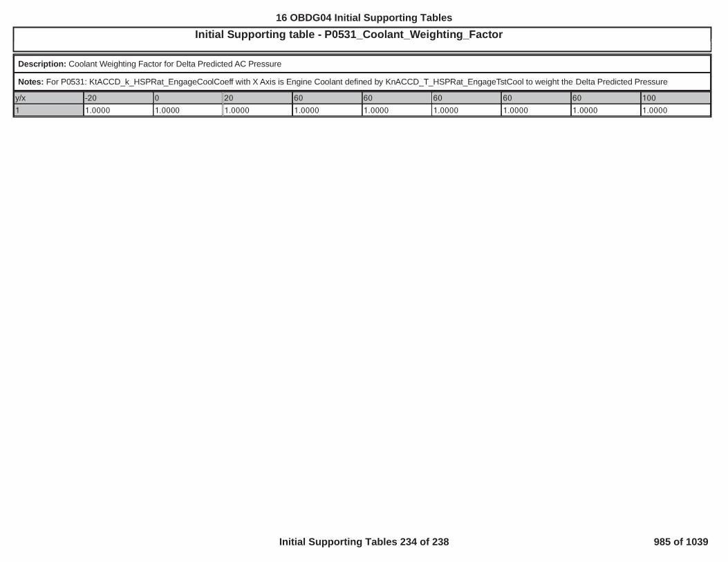
Initial Supporting table - P0531_Coolant_Weighting_Factor5
Description: Coolant Weighting Factor for Delta Predicted AC Pressure
Notes: For P0531: KtACCD_k_HSPRat_EngageCoolCoeff with X Axis is Engine Coolant defined by KnACCD_T_HSPRat_EngageTstCool to weight the Delta Predicted Pressure
y/x -20 0 20 60 60 60 60 60 100
1 1.0000 1.0000 1.0000 1.0000 1.0000 1.0000 1.0000 1.0000 1.0000
986
16 OBDG04 Initial Supporting Tables
Initial Supporting Tables 234 of 238 985 of 1039

Initial Supporting table - P0531_Delta_Predicted_ Pressure5
Description: AC High Side Pressure Sensor Sensor Engage Test Predicted Delta Pressure
Notes: For P0531: KtACCD_p_HSPR_DeltaPredicted with X Axis is defined by KnACCD_T_HSPRat_EngageTstAmb and Y Axis is defined by KnACCD_v_HSPRat_EngageTstVehSpd
y/x -20 0 20 60 60 60 60 60 100
0 0.00 5.00 20.00 50.00 50.00 50.00 50.00 50.00 100.00
5 0.00 5.00 20.00 50.00 50.00 50.00 50.00 50.00 100.00
20 0.00 5.00 20.00 50.00 50.00 50.00 50.00 50.00 100.00
50 0.00 5.00 20.00 50.00 50.00 50.00 50.00 50.00 100.00
50 0.00 5.00 20.00 50.00 50.00 50.00 50.00 50.00 100.00
50 0.00 5.00 20.00 50.00 50.00 50.00 50.00 50.00 100.00
50 0.00 5.00 20.00 50.00 50.00 50.00 50.00 50.00 100.00
50 0.00 5.00 20.00 50.00 50.00 50.00 50.00 50.00 100.00
100 0.00 5.00 20.00 50.00 50.00 50.00 50.00 50.00 100.00
987
16 OBDG04 Initial Supporting Tables
Initial Supporting Tables 235 of 238 986 of 1039

Initial Supporting table - P0531_Delta_Predicted_Quality_FactorTES 5
Description: Delta Predicted Qualtiy Factor for the Engage Test
Notes: For P0531: KtACCD_k_HSPR_QualFactor with X Axis is defined by KnACCD_T_HSPRat_EngageTstAmb and Y Axis is defined by KnACCD_v_HSPRat_EngageTstVehSpd
y/x -20 0 20 60 60 60 60 60 100
0 0.00999 0.04999 0.20000 0.50000 0.50000 0.50000 0.50000 0.50000 0.99998
5 0.00999 0.04999 0.20000 0.50000 0.50000 0.50000 0.50000 0.50000 0.99998
20 0.00999 0.04999 0.20000 0.50000 0.50000 0.50000 0.50000 0.50000 0.99998
50 0.00999 0.04999 0.20000 0.50000 0.50000 0.50000 0.50000 0.50000 0.99998
50 0.00999 0.04999 0.20000 0.50000 0.50000 0.50000 0.50000 0.50000 0.99998
50 0.00999 0.04999 0.20000 0.50000 0.50000 0.50000 0.50000 0.50000 0.99998
50 0.00999 0.04999 0.20000 0.50000 0.50000 0.50000 0.50000 0.50000 0.99998
50 0.00999 0.04999 0.20000 0.50000 0.50000 0.50000 0.50000 0.50000 0.99998
100 0.00999 0.04999 0.20000 0.50000 0.50000 0.50000 0.50000 0.50000 0.99998
988
16 OBDG04 Initial Supporting Tables
Initial Supporting Tables 236 of 238 987 of 1039

Initial Supporting table - P0531_FanSpeed_Weighting_Factor5
Description: FanSpeed Weighting Factor for Delta Predicted AC Pressure
Notes: For P0531: KtACCD_k_HSPRat_EngageFanCoeff with X Axis is Fan Speed as desfined by KnACCD_Pct_HSPRat_EngageTestFan to weight the Delta Predicted Pressure
y/x 0 5 20 50 50 50 50 50 100
1 1 1 1 1 1 1 1 1 1
989
16 OBDG04 Initial Supporting Tables
Initial Supporting Tables 237 of 238 988 of 1039

Initial Supporting table - P0606_Program Sequence Watch Enable f(Core, Loop Time)5
Description: The enabling flags for the program sequence watch as a function of processor core and operating loop time sequence.
Notes: P0606, KaPISD_b_ProgSeqWatchEnbl
y/x CeTSKR_e_CPU CeTSKR_e_CPU2 CeTSKR_e_CPU3 CeTSKR_e_CPU4CePISR_e_6p25msSeq 1 0 0 0
CePISR_e_12p5msSeq 1 0 0 0
CePISR_e_25msSeq 1 0 0 0
CePISR_e_LORES_C 1 0 0 0
990
16 OBDG04 Initial Supporting Tables
Initial Supporting Tables 238 of 238 989 of 1039

Bundle Name: 5VoltReferenceB_FAP0651Bundle Name: AAP_AAP2_SnsrStabFAP227EBundle Name: AAP_AAP5_SnsrCktFAP2228, P2229Bundle Name: AAP_AAP5_SnsrStabFAP2230Bundle Name: AAP_AmbientAirPresDfltdP2227, P2228, P2229, P2230, P00C7AAP_AmbientAirPresDfltd - Other Definitions:
Bundle Name: AAP_AmbPresSnsrTFTKOP2227, P2228, P2229, P2230, P00C7AAP_AmbPresSnsrTFTKO - Other Definitions:
Bundle Name: AAP_SnsrCktFANaturally aspirated: P2228, P2229. Turbocharged: P0237, P0238Bundle Name: AAP_SnsrCktFPNaturally aspirated: P2228, P2229. Turbocharged: P0237, P0238Bundle Name: AAP_SnsrFANaturally Aspirated: P2227, P2228, P2229, P2230. Turbocharged: P0237, P0238.Bundle Name: AAP2_SnsrCktFAP2228, P2229Bundle Name: AAP2_SnsrCktFPP2228, P2229Bundle Name: AAP2_SnsrFAP2227, P2228, P2229, P2230Bundle Name: AAP3_SnsrCktFAP222C, P222DBundle Name: AAP3_SnsrCktFPP222C, P222DBundle Name: AccCktLo_FAP2537Bundle Name: AcceleratorPedalFailureP2122, P2123, P2127, P2128, P2138, P0697, P06A3Bundle Name: ACCMLostCommU016B
16 OBDG04 Fault Bundle Definitions
Fault Bundle Definitions 1 of 50 990 of 1039

Bundle Name: ACFailedOnSDSee ACCM DocumentBundle Name: ACHighSidePressSnsrCktFAP0532, P0533Bundle Name: ACThrmlRefrigSpdVldSee ACCM DocumentBundle Name: AIC_AirCntrlShtOffAction
AIC_AirCntrlShtOffAction - Other Definitions:Enumerative that is set to CeAICR_e_CntrlActv (air control is in closed loop) if NONE of the following conditions are verified:
1. Air control is shut off due to an air system fault2. Engine mode is ready3. Engine mode is cranking4. HP EGR actuator, LP EGR actuator or Throttle actuator are NOT available5. Zero torque condition is active (for all combustion modes except for the Rich ones)6. EGR control request is maximum: TRUE if Air setpoint = [mg]1,800.007. Large injected fuel condition is active:
FALSE for SCR service check, C2, C3 DeSOx Rich, DeNOx combustion modes.For other combustion modes, it is TRUE if Fuel request is higher than a high threshold, with hysteresis: if the condition is TRUE, then it remains TRUE until the Fuel
request drops below a low threshold.
These thresholds depend on specific calibrations, related to different combustion modes (look at the variable VeAICR_e_CombMode), which are function of the engine speed:
o D1 and D3:� High: [mm^3]AIC_AirCntrlShtOffActn: Fuel High Threshold for D1 and D3� Low: [mm^3]AIC_AirCntrlShtOffActn: Fuel Low Threshold for D1 and D3
o D2 and D4:� High: [mm^3]AIC_AirCntrlShtOffActn: Fuel High Threshold for D2 and D4� Low: [mm^3]AIC_AirCntrlShtOffActn: Fuel Low Threshold for D2 and D4
o DeSOx Lean:� High: [mm^3]AIC_AirCntrlShtOffActn: Fuel High Threshold for L3� Low: [mm^3]AIC_AirCntrlShtOffActn: Fuel Low Threshold for L3
o SCR modes:� High: [mm^3]AIC_AirCntrlShtOffActn: Fuel High Threshold for SCR� Low: [mm^3]AIC_AirCntrlShtOffActn: Fuel Low Threshold for SCR
o All other modes:� High: [mm^3]AIC_AirCntrlShtOffActn:Fuel High Threshold for others� Low: [mm^3]AIC_AirCntrlShtOffActn: Fuel Low Threshold for others
8. Engine Coolant Temperature too high condition is active:FALSE for SCR service check, DeSOx Rich, DeNOx combustion modes.For other combustion modes, it is TRUE if Engine Coolant Temperature is higher than a high threshold, with hysteresis: if the condition is TRUE, then it remains TRUE until the
Engine Coolant Temperature drops below a low threshold.
These thresholds depend on specific calibrations, related to different combustion modes (look at the variable VeAICR_e_CombMode):
16 OBDG04 Fault Bundle Definitions
Fault Bundle Definitions 2 of 50 991 of 1039

o DPF and HCS modes:� High: [°C]117.00� Low: [°C]114.00
o DeSOx Lean:� High: [°C]117.00� Low: [°C]114.00
o C3:� High: [°C]117.00� Low: [°C]114.00
o SCR modes:� High: [°C]117.00� Low: [°C]114.00
o All other modes:� High: [°C]117.00� Low: [°C]114.00
9. Engine Coolant Temperature too low condition is active:If Engine coolant temperature is NOT higher than the global temperature threshold for OBDII market (OBD Coolant Enable Criteria==FALSE) ANDECT_TooLow==TRUE:This is FALSE for SCR service check, DeSOx Rich, DeNOx combustion modes.For other combustion modes, it is TRUE if Engine Coolant Temperature is lower than a low threshold, with hysteresis: if the condition is TRUE, then it remains TRUE until
the Engine Coolant Temperature goes above a high threshold.
These thresholds depend on specific calibrations, related to different combustion modes (look at the variable VeAICR_e_CombMode):
o DPF and HCS modes (thresholds depending on the Outside Air Temperature):� High: [°C]AIC_AirCntrlShtOffActn: ECT Too Low Hysteresis High Threshold for DPF� Low: [°C]AIC_AirCntrlShtOffActn: ECT Too Low Hysteresis Low Threshold for DPF
o DeSOx Lean:� High: [°C]13.00� Low: [°C]10.00
o C3:� High: [°C]13.00� Low: [°C]10.00
o SCR modes (thresholds depending on the Outside Air Temperature):� High: [°C]AIC_AirCntrlShtOffActn: ECT Too Low Hysteresis High Threshold for SCR� Low: [°C]AIC_AirCntrlShtOffActn: ECT Too Low Hysteresis Low Threshold for SCR
o All other modes (thresholds depending on the Outside Air Temperature):� High: [°C]AIC_AirCntrlShtOffActn: ECT Too Low Hysteresis High Threshold for others� Low: [°C]AIC_AirCntrlShtOffActn: ECT Too Low Hysteresis Low Threshold for others
10. Intake Air Temperature too high condition is active:FALSE for DeSOx Rich, DeNOx combustion modes.For other combustion modes, it is TRUE if Intake Air Temperature is higher than a high threshold, with hysteresis: if the condition is TRUE, then it remains TRUE until the
Intake Air Temperature drops below a low threshold.
These thresholds depend on specific calibrations, related to different combustion modes (look at the variable VeAICR_e_CombMode):
o DPF and HCS modes:
16 OBDG04 Fault Bundle Definitions
Fault Bundle Definitions 3 of 50 992 of 1039

� High: [°C]80.00� Low: [°C]70.00
o SCR service check mode:� High: [°C]80.00� Low: [°C]70.00
o DeSOx Lean:� High: [°C]80.00� Low: [°C]70.00
o SCR modes:� High: [°C]80.00� Low: [°C]70.00
o All other modes:� High: [°C]80.00� Low: [°C]70.00
11. Intake Air Temperature too low condition is active:FALSE for DeSOx Rich, DeNOx combustion modes.For other combustion modes, it is TRUE if Intake Air Temperature is lower than a low threshold, with hysteresis: if the condition is TRUE, then it remains TRUE until the
Intake Air Temperature goes above a high threshold.
These thresholds depend on specific calibrations, related to different combustion modes (look at the variable VeAICR_e_CombMode):
o DPF and HCS modes:� High: [°C]-40.00� Low: [°C]-43.00
o SCR service check mode:� High: [°C]-50.00� Low: [°C]-55.00
o DeSOx Lean:� High: [°C]-50.00� Low: [°C]-55.00
o SCR modes:� High: [°C]-50.00� Low: [°C]-55.00
o All other modes:� High: [°C]-50.00� Low: [°C]-55.00
12. Ambient pressure too low condition is active:FALSE for DPF and HCS, SCR service check, LNT (DeNOx, DeSOx Rich and DeSOx Lean) combustion modes.For other combustion modes, it is TRUE if Ambient Pressure is lower than a low threshold, with hysteresis: if the condition is TRUE, then it remains TRUE until the
Ambient Pressure goes above a high threshold.
These thresholds depend on specific calibrations, related to different combustion modes (look at the variable VeAICR_e_CombMode):
o SCR modes:� High: [kPa]72.00� Low: [kPa]70.00
o C3:
16 OBDG04 Fault Bundle Definitions
Fault Bundle Definitions 4 of 50 993 of 1039

� High: [kPa]72.00� Low: [kPa]70.00
o All other modes:� High: [kPa]72.00� Low: [kPa]70.00
13. Overlong idle condition is active:FALSE for DPF, SCR service check, LNT (DeNOx, DeSOx Rich and DeSOx Lean) combustion modes.For other combustion modes, it is TRUE if Engine Speed is lower than a threshold and this condition lasts for a calibrate-able t imer.
The threshold and the timer depend on specific calibrations, related to different combustion modes (look at the variable VeAICR_e_CombMode):
o SCR modes:� Threshold: [rpm]600.00� Timer: [s]409.59
o All other modes:� Threshold: [rpm]600.00� Timer: [s]409.59
14. MAF drift intrusive test is requested:TRUE if the following conditions (in AND) are satisfied:• MAF sensor rationality monitoring - intrusive airflow drift test is enabled (see the documentation related to P0101)• Engine is in idle: [rpm] < engine speed < [rpm]700.00 1,200.00
for a debouncing time > [s]1.00• Intake Manifold Pressure is steady state: |IntkPres – IntkPres_old| < [kPa]6.00• Intake Manifold Pressure is in range: [kPa] < IntkPres < [kPa]70.00 150.00
Conditions from 7 to 14 in AND with: Exhaust Gas Overtemperature NOT detected ( ==FALSE)EGT_ExhOverTemp
Conditions 8 and from 10 to 12 also in AND with (EOBD only): EGR intrusive test NOT enabledBundle Name: AIC_AirShtOffReq
AIC_AirShtOffReq - Other Definitions:, , , , ,AAP_AmbientAirPresDfltd AAP_AmbPresSnsrTFTKO ECT_Sensor_FA ECT_Sensor_TFTKO MnfdTempSensorFA
, , , , ,MnfdTempSensorTFTKO CrankSensor_FA CrankSensor_TFTKO LPE_TempSnsrFA LPE_TempSnsrTFTKO, , , ,MAF_MAF_SnsrCktFlt MAF_MAF_SnsrOfstFA MAF_MAF_SnsrOfstTFTKO MAF_MAF_SnsrPerfFA
, , , , ,MAF_MAF_SnsrPerfTFTKO MAP_EngOffPressFA MAP_EngOffPressTFTKO MAP_SensorFA MAP_SensorTFTKO, , , , ,CEB_ActrCktLoFlt EGR_IntkTempTooHiTFTKO EGR_PstnShtOffReq FUL_EGR_InjSysFA LPE_PstnShtOffReq
, , , , ,SWC_SwirlShtOffReq TPS_PstnShtOffReq AIC_BstHiFsftActv AIC_AirDvtnTFTKO DPF_FR_LoFA LPE_VlvOvrHtTFTKOBundle Name: AIC_BstCntrlCL
AIC_BstCntrlCL - Other Definitions:Boolean that is set to TRUE if the following conditions are satisfied (conditions in AND):
• Fuel request is higher than a “On” threshold, with hysteresis: if the condition is TRUE, then it remains TRUE until the Fuel request drops below a “Off” threshold.
16 OBDG04 Fault Bundle Definitions
Fault Bundle Definitions 5 of 50 994 of 1039

These thresholds depend on specific calibrations, related to different combustion modes (look at the variable VeAICR_e_CombMode), which are function of the enginespeed:
o C2 and C3:� On: [mm^3]AIC_BstCntrlCL: Fuel Request On Threshold for C2 and C3� Off: - [mm^3]AIC_BstCntrlCL: Fuel Request On Threshold for C2 and C3 7.00
o D1, D3 and HC unloading:� On: [mm^3]AIC_BstCntrlCL: Fuel Request On Threshold for D1 and D3� Off: - [mm^3]AIC_BstCntrlCL: Fuel Request On Threshold for D1 and D3 6.00
o D2 and D4:� On: [mm^3]AIC_BstCntrlCL: Fuel Request On Threshold for D2 and D4� Off: - [mm^3]AIC_BstCntrlCL: Fuel Request On Threshold for D2 and D4 7.00
o V3:� On: [mm^3]AIC_BstCntrlCL: Fuel Request On Threshold for V3� Off: - [mm^3]AIC_BstCntrlCL: Fuel Request On Threshold for V3 5.00
o S2:� On: [mm^3]AIC_BstCntrlCL: Fuel Request On Threshold for S2� Off: - [mm^3]AIC_BstCntrlCL: Fuel Request On Threshold for S2 5.00
o S3:� On: [mm^3]AIC_BstCntrlCL: Fuel Request On Threshold for S3� Off: - [mm^3]AIC_BstCntrlCL: Fuel Request On Threshold for S3 5.00
o Default:� On: [mm^3]AIC_BstCntrlCL: Fuel Request On Threshold for others� Off: - [mm^3]AIC_BstCntrlCL: Fuel Request On Threshold for others 5.00
• Turbo configuration is VGT and the VGT actuator is a DC motor, OR "Shared High Side driver driven closed"• Run Crank Ignition in range: Battery voltage > [V]11.00• Relay in range: Powertrain relay voltage > [V]11.00• No faults
Bundle Name: AIC_BstSysDiagDenomDsblP226BAIC_BstSysDiagDenomDsbl - Other Definitions:
, , , , , , , ,VGT_ActCktFA WGA_ActrCktFA MAP_SensorFA TPS_PstnDvtnFA AIC_DCMtrGenericPstnFA AAP_AmbientAirPresDfltd AIC_OAT_SignalFA ECT_Sensor_FA TPS_PstnSnsrFABundle Name: AIC_DCMtrGenericPstnFAP2564, P2565 , P16B0, P16B1, P16B2, P003A, P2598, P2599AIC_DCMtrGenericPstnFA - Other Definitions:
,VGT_PstnCntrlFA VGT_PstnSnsrFABundle Name: AIC_EGR_FlowDiagAirTempFA
AIC_EGR_FlowDiagAirTempFA - Other Definitions:, ,IAT_SensorFA MnfdTempSensorFA AIC_OAT_SignalFA
Bundle Name: AIC_GenericBstSysFltP0234, P0299, P2263, P226BAIC_GenericBstSysFlt - Other Definitions:
16 OBDG04 Fault Bundle Definitions
Fault Bundle Definitions 6 of 50 995 of 1039

, , , , , ,VGT_PstnSnsrFA VGT_PstnSnsrTFTKO VGT_PstnCntrlFA VGT_PstnCntrlTFTKO VGT_ActCktFA VGT_ActCktTFTKO, , , ,WGA_ActrCktFA WGA_ActrCktTFTKO MAP_SensorFA MAP_SensorTFTKO,TPS_PstnDvtnFA TPS_PstnDvtnTFTKO
Bundle Name: AIC_OAT_SignalFA
AIC_OAT_SignalFA - Other Definitions:, .OAT_OAT_SnsrNonEmissFA OAT_PtEstFiltFA
Bundle Name: AmbPresDfltdStatusBaro Sensor Present: P2227, P2228, P2229, P2230. No Baro Sensor Present: P0101, P0102, P0103, P0106, P0107, P0108, P0111, P0112, P0113, P0114, P0121, P0122, P0123,P012B, P012C, P012D, P0222,P0223, P1221
Bundle Name: AnyCamPhaser_FAP0010, P0011, P0013, P0014, P0020, P0021, P0023, P0024, P2088, P2089, P2090, P2091, P2092, P2093, P2094, P2095, P05CC, P05CD, P05CE, P05CF,
Bundle Name: AnyCamPhaser_TFTKOP0010, P0011, P0013, P0014, P0020, P0021, P0023, P0024, P2088, P2089, P2090, P2091, P2092, P2093, P2094, P2095, P05CC, P05CD, P05CE, P05CF,
Bundle Name: CamLctnExhFAP0017, P0019, P0365, P0366, P0390, P0391Bundle Name: CamLctnIntFAP0016, P0018, P0340, P0341, P0345, P0346Bundle Name: CamSensorAnyLctnTFTKOP0016, P0017, P0018, P0019, P0340, P0341, P0345, P0346, P0365, P0366, P0390, P0391Bundle Name: CAN_LostComm_FltN_BusB_NOxSnsr_AU029DBundle Name: CAN_LostComm_FltN_BusB_NOxSnsr_BU029EBundle Name: CAT_Cat2_SysEffLoB1_FAP0422Bundle Name: CAT_CatPresDropFlt
CAT_CatPresDropFlt - Other Definitions:|| ||EGT_SnsrCatUpFlt EXF_TotExhCatUpFlt EGP_PresCatDwnFlt
Bundle Name: CAT_CatSysEffLoB1_FAP0421Bundle Name: CAT_HC_Cat2_DwnFlt
CAT_HC_Cat2_DwnFlt - Other Definitions:|| || || || || || ||HCI_HC_dm_Cat2_UpFlt OXY_O2_Cat2_UpFlt EXF_TotExhCat2_UpFlt EGT_TempCat2_UpFlt EGP_PresCat2_UpFlt AmbientAirDefault VehicleSpeedSensor_FA
CAT_OutsideTempFA
16 OBDG04 Fault Bundle Definitions
Fault Bundle Definitions 7 of 50 996 of 1039

Bundle Name: CAT_OutsideTempFA
CAT_OutsideTempFA - Other Definitions:OAT_PtEstFiltFABundle Name: CAT_PM_Cat2_DwnVld
CAT_PM_Cat2_DwnVld - Other Definitions:SOT_PM_Cat2_UpVldBundle Name: CEB_ActrCktFAP245A , P245C, P245DCEB_ActrCktFA - Other Definitions:
Bundle Name: CEB_ActrCktLoFAP245CBundle Name: CET_DNSS_FAP142A, P1429, P040E, P040C, P040D, P040BBundle Name: CET_UPSS_FAP1427, P1428, P041C, P041D, P041E, P041BBundle Name: CET_UPSS_TFTKOP1427, P1428, P041C, P041D, P041E, P041BBundle Name: CIT_CAC_DwnCktFAP10D7, P10D6Bundle Name: CIT_CAC_DwnFAP10D6, P10D7, P10D8, P10D5Bundle Name: CIT_CAC_DwnSelfCorFAP10D8Bundle Name: CIT_CAC_UpCktFAP007D, P007CBundle Name: CIT_CAC_UpFAP007D, P007C, P007E, P007BBundle Name: CIT_CAC_UpSelfCorFAP007EBundle Name: ClchPstnSnsrPerf FAP0806Bundle Name: ClutchPstnSnsr FAP0806, P0807, P0808Bundle Name: ClutchPstnSnsrCktHi FAP0808Bundle Name: ClutchPstnSnsrCktLo FA
16 OBDG04 Fault Bundle Definitions
Fault Bundle Definitions 8 of 50 997 of 1039

P0807Bundle Name: ClutchPstnSnsrNotLearnedP080ABundle Name: CrankSensor_FAP0335, P0336Bundle Name: CrankSensor_TFTKOP0335, P0336Bundle Name: DPF_DPF_St
DPF_DPF_St - Other Definitions:DPF_DPF_St is equal to:- Soot Loading modes (no DPF regeration) if = 0DPF_EnblDPF- Regeneration modes if = 1DPF_EnblDPFBundle Name: DPF_EnblDPF
DPF_EnblDPF - Other Definitions:DPFR_EnblDPF = 1 if:- Combustion mode is DPF Regeneration modes.Bundle Name: DPF_FR_CalcDsbl
DPF_FR_CalcDsbl - Other Definitions:OR OR OREGT_SnsrDPF_UpFlt EGP_DiffPresSnsrFlt EXF_TotExhDPF_UpFlt AmbPresDfltdStatus
Bundle Name: DPF_LastRgnAvg
DPF_LastRgnAvg - Other Definitions:DPF_LastRgnAvg is calculated as the average distance between two completed regenerations.Bundle Name: DPF_ResistFlowCalcOff
DPF_ResistFlowCalcOff - Other Definitions:The Resistive flow calculation is disabled, DPF_ResistFlowCalcOff = 1, if one of those conditions is fulfilled for calibratable debouncing time [sec]:0.00- DPF Differential pressure sensor reading is below [KPa]1.00- Estimated exhaust gas volume flow rate is below [l/s]25.00- and are both = 1DPF_FR_CalcDsbl 0.00. Derivative of pressure drop across the DPF is above [KPa/sec]5.00- is belowDPF_LastRgnAvg -1.00- Fuel Request is outside the range identified by andDPF_ResistFlowDsblLo DPF_ResistFlowDsblHi- The regeneration is on going and with the DPF upstream tempearture greater than (with hysteresys )DPF_EffRgnHysHi DPF_EffRgnHysLoBundle Name: DPF_ResistFlowFltd
DPF_ResistFlowFltd - Other Definitions:It is the Filtered exhaust gas resistive flow, that indicates the amount of soot present inside in the DPF.The flow resistance depends on Pressure difference measured by exhaust pressure sensor(EGP) , between upstream and downstream DPF, and Exhaust Flow.
16 OBDG04 Fault Bundle Definitions
Fault Bundle Definitions 9 of 50 998 of 1039

The Filtered Flow Resistance is filtered by a low pass filter with a calibratable time constant in order to obtain the mean value for diagnostic purposes.
Bundle Name: DPF_TempDPF_DwnFlt
DPF_TempDPF_DwnFlt - Other Definitions:NOT(NOT AND NOT AND NOT AND NOT AND NOT AND NOTEGP_PresDPF_UpFlt EXF_TotExhDPF_UpFlt VehicleSpeedSensor_FA EGT_SnsrDPF_UpFlt OAT_PtEstFiltFA
AND NOT AND NOT )HCI_HC_dm_DPF_UpFlt EXM_EQR_ExhMnfdNotVld EGT_TempCat2_DwnFltBundle Name: ECT_Sensor_Ckt_FAP0117, P0118Bundle Name: ECT_Sensor_Ckt_FPP0117, P0118Bundle Name: ECT_Sensor_Ckt_TFTKOP0117, P0118Bundle Name: ECT_Sensor_DefaultDetectedP0116, P0117, P0118, P0119, P111EBundle Name: ECT_Sensor_FAP0116, P0117, P0118, P0119, P0128, P111EBundle Name: ECT_Sensor_Perf_FAP0116, P111EBundle Name: ECT_Sensor_TFTKOP0116, P0117, P0118, P0119, P0128, P111EECT_Sensor_TFTKO - Other Definitions:
Bundle Name: EGP_DiffPresOfstTFTKOP2452Bundle Name: EGP_DiffPresQckChgFltP2456Bundle Name: EGP_DiffPresSnsrCktFltP2454, P2455Bundle Name: EGP_DiffPresSnsrFltP2452, P2453, P2454, P2455, P2456Bundle Name: EGP_DiffPresSnsrRatFltP2453EGP_DiffPresSnsrRatFlt - Other Definitions:EGP_DiffPresSnsrFA and with EGP_DiffPresSnsrTFTKOBundle Name: EGP_DiffPresStkFltPresentP2453Bundle Name: EGP_PresCatDwnFlt
16 OBDG04 Fault Bundle Definitions
Fault Bundle Definitions 10 of 50 999 of 1039

EGP_PresCatDwnFlt - Other Definitions:,EGP_PresDEFMV_UpFlt EPM_PresPipe1_DropFlt
Bundle Name: EGP_PresCatUpFlt
EGP_PresCatUpFlt - Other Definitions:,CAT_CatPresDropFlt EGP_PresCatDwnFlt
Bundle Name: EGP_PresDPF_DwnFlt
EGP_PresDPF_DwnFlt - Other Definitions:in AND withAAP_AmbPresSnsrTFTKO AAP_AmbientAirPresDfltd
Bundle Name: EGP_PresDPF_UpFlt
EGP_PresDPF_UpFlt - Other Definitions:, , , ( in AND with )EGP_DiffPresSnsrFlt EXF_TotExhMufflerUpFlt EGT_SnsrDPF_DwnFlt AAP_AmbPresSnsrTFTKO AAP_AmbientAirPresDfltd
Bundle Name: EGP_PresHCI_UpFlt
EGP_PresHCI_UpFlt - Other Definitions:,EPM_PresPipe4_DropFlt EGP_PresCat2_UpFlt
Bundle Name: EGP_PresSCR_DwnFlt
EGP_PresSCR_DwnFlt - Other Definitions:,EPM_PresPipe3_DropFlt EGP_PresHCI_UpFlt
Bundle Name: EGP_PresSCR_UpFlt
EGP_PresSCR_UpFlt - Other Definitions:,SCR_SCR_PresDropFlt EGP_PresSCR_DwnFlt
Bundle Name: EGP_PresTurbDwnFlt
EGP_PresTurbDwnFlt - Other Definitions:,CAT_CatPresDropFlt EGP_PresCatDwnFlt
Bundle Name: EGR_MtrCurrLimTFTKOP140FBundle Name: EGR_PstnDvtnFAP042E, P042FBundle Name: EGR_PstnShtOffReqP0403, P0405, P0406, P042E, P042F, P049D, P0489, P0490, P1402, P1407, P140F, P1424Bundle Name: EGR_PstnShtOffReqFAP0403, P0405, P0406, P042E, P042F, P049D, P0489, P0490, P1402, P1407, P140F, P1424Bundle Name: EGR_PstnSnsrFAP0405, P0406, P049D
16 OBDG04 Fault Bundle Definitions
Fault Bundle Definitions 11 of 50 1000 of 1039

Bundle Name: EGR_PstnSnsrFltP0405, P0406, P049DBundle Name: EGR_VlvTempNotVld
EGR_VlvTempNotVld - Other Definitions:, , ,CET_DNSS_FA CET_DNSS_TFTKO CET_UPSS_FA CET_UPSS_TFTKO
Bundle Name: EGR_VlvTotFlowNomNotVldP0405, P0406, P049DEGR_VlvTotFlowNomNotVld - Other Definitions:
, , ,EGR_VlvTempNotVld MAP_SensorFA MAP_SensorTFTKO EXM_ExhMnfdPresNotVldBundle Name: EGR_VlvTotFlowNotValidP0405, P0406, P049DEGR_VlvTotFlowNotValid - Other Definitions:INM_IntkGapNotValidBundle Name: EGT_Avg
EGT_Avg - Other Definitions:Reference Temperature, EGT_Avg, at system start up is definited as:The reference temperature at system start-up is an average calculation done using all temperature sensors present in the system. The usage of each temperature in the average calculationshall be decided via calibration (one for each sensor) and only if the sensor is no faulty.The reference temperature shall be calculated only if all the following conditions are fulfilled:- System supplied but engine still not running ( also crack phase excluded). If after the crank phase the engine is not running but it is turned back to key on state the calculation shall bedisable for a calibratable time- Time from the last engine shutdown greater than a calibratable threshold( )28,800.00- At least four sensor are available for the reference temperature calculation- If after the crank phase the engine is not running but it is turned back to key on state the calculation shall be disable until the engine will run
The reference temperature shall be calculated as following:T_AvrKeyOn= (( T_i) - T_Max- T_Min) / (n-2)where:T_i : i-th system temperatureT_Max: Maximum temperature readT_Min: Minimum temperature readn: number of temperature sensors used for the reference temperature calculationBundle Name: EGT_DsblCL
EGT_DsblCL - Other Definitions:VeEGTC_e_DsblCL == CeEGTC_e_AllCondEnblCL (CLC Enabled) if:- Combustion Mode equal to one of allowed modes (DPF, DeSOx Lean)- Post Injection is enabled ( )FUL_PostEnbl- Post Injection shall be currently released or Post Release Check shall be disabled ( )0.00- If Post Release Check is enabled ( ) , Post Injection shall be enabled ( ) and it shall be currently released or not released for less than a calibratable debouncing time0.00 FUL_PostEnbl( ) while post injection open loop plus previous closed loop quantity are not below a minimum quantity .1.00 0.00- Fuel Request above calibratable range : Fuel Requested > with hysteresisEGT_FuelReqHysHiThrsh_DPF EGT_FuelReqHysLoThrsh_DPF
16 OBDG04 Fault Bundle Definitions
Fault Bundle Definitions 12 of 50 1001 of 1039

- Catalyst Down Temperature Sensor < [°C] AND with Post Injection Control PID > 0 [mm3]700.00- No Fault on Catalyst Down Temperature Sensor ( )EGT_SnsrCatDwnFltBundle Name: EGT_ExhGas1_CktTFTKOP0546, P0545Bundle Name: EGT_ExhGas1_FAP0546, P0545, P2081, P2080, P113BBundle Name: EGT_ExhGas1_TFTKOP0546, P0545, P2081, P2080, P113BBundle Name: EGT_ExhGas2_CktTFTKOP2033, P2032Bundle Name: EGT_ExhGas2_FAP2033, P2032, P2085, P2084, P113CBundle Name: EGT_ExhGas2_TFTKOP2033, P2032, P2085, P2084, P113CBundle Name: EGT_ExhGas3_CktTFTKOP242D, P242CBundle Name: EGT_ExhGas3_FAP242D, P242C, P242E, P242B, P113DBundle Name: EGT_ExhGas3_TFTKOP242D, P242C, P242E, P242B, P113DBundle Name: EGT_ExhGas4_CktTFTKOP2471, P2470Bundle Name: EGT_ExhGas4_FAP2471, P2470, P2472, P246F, P113EBundle Name: EGT_ExhGas4_TFTKOP2471, P2470, P2472, P246F, P113EBundle Name: EGT_ExhGas5_CktTFTKOP2482, P2481Bundle Name: EGT_ExhGas5_FAP2481, P2482, P2483, P2484, P113FBundle Name: EGT_ExhGas5_TFTKOP2481, P2482, P2483, P2484, P113FBundle Name: EGT_ExhOverTempP200C, P200EBundle Name: EGT_HC_CL_Enbl
EGT_HC_CL_Enbl - Other Definitions:EGT_HC_CL_Enbl = 1 if:- HC Control is enabled ( = 1)EGT_HC_ControlEnbl
16 OBDG04 Fault Bundle Definitions
Fault Bundle Definitions 13 of 50 1002 of 1039

- No Fault on DPF Up Temperature Sensor ( )EGT_SnsrDPF_UpFlt- DPF Up Temperature Sensor NOT above threshold KeEGTC_T_DPF_UpTempThrshDsblCL while HC Injection Control PID > 0Bundle Name: EGT_HC_ControlEnbl
EGT_HC_ControlEnbl - Other Definitions:EGT_HC_ControlEnbl = 1 if:- HC Injector is supported by exhaust layout ( )EXC_HCI_Enbl- Combustion Mode equal to one of allowed modes (DPF)- No Fault on HC Injector ( )HCI_GenericShtOffReq- HC Injector control enabled ( )HCI_HCI_CntrlEnblBundle Name: EGT_SnsrCat2_DwnFltP2470, P2471, P2472, P246F, P113EBundle Name: EGT_SnsrCatDwnFltP2033, P2032, P2085, P2084, P113CBundle Name: EGT_SnsrCatUpFltP0546, P0545, P2081, P2080, P113BBundle Name: EGT_SnsrDPF_DwnFltP2481, P2482, P2483, P2484, P113FBundle Name: EGT_SnsrDPF_DwnPresent
EGT_SnsrDPF_DwnPresent - Other Definitions:GetEGTR_b_SnsrDPF_DwnPresent= 1 if:- If = CeEXCR_C_UI_SCR_HCI_C_DPF andCeEXCR_e_C_UI_SCR_HCI_C_DPF
= CeEXCR_e_EGT5_DPF_DwnCeEXCR_e_EGT5_DPF_DwnBundle Name: EGT_SnsrDPF_UpFAP2470, P2471, P2472, P246F, P113EBundle Name: EGT_SnsrDPF_UpFltP2470, P2471, P2472, P246F, P113EBundle Name: EGT_SnsrDPF_UpTFTKOP2470, P2471, P2472, P246F, P113EBundle Name: EGT_SnsrTurbDwnFltP0546, P0545, P2081, P2080, P113BBundle Name: EGT_TempAvgVld
EGT_TempAvgVld - Other Definitions:If EGT_TempAvgVld indicates that the reference temperature calculation , , is on going.EGT_AvgBundle Name: EGT_TempCat2_DwnFltP2470, P2471, P2472, P246F, P113EBundle Name: EGT_TempCat2_UpFlt
16 OBDG04 Fault Bundle Definitions
Fault Bundle Definitions 14 of 50 1003 of 1039

EGT_TempCat2_UpFlt - Other Definitions:EPM_TempPipe4_DwnFltBundle Name: EGT_TempSCR_DwnFlt
EGT_TempSCR_DwnFlt - Other Definitions:SCR_TempSCR_DwnFltBundle Name: EGT_TempSCR_UpFlt
EGT_TempSCR_UpFlt - Other Definitions:EPM_TempPipe2_DwnFltBundle Name: EngineMisfireDetected_FAP0300, P0301, P0302, P0303, P0304, P0305, P0306, P0307, P0308Bundle Name: EngineModeNotRunTimer_FAP2610Bundle Name: EngineModeNotRunTimerErrorP2610Bundle Name: EnginePowerLimitedP0068, P00C8, P00C9, P00CA, P0090, P0091, P0092, P0122, P0123, P0191, P0192, P0193, P0222, P0223, P0601, P0604, P0606, P0697, P06A3, P06DB,P06D2, P06DE, P0A1D, P1104, P127A, P127C, P127D, P15F2, P160D, P160E, P1682, P16A0, P16A1, P16A2, P16A7, P16F3, P2100, P2101, P2102, P2103,P2122, P2123, P2127, P2128, P2135, P2138, P215B, P2176, P228C, P228D, U0073, U0074, U0293, U1817Bundle Name: EngineTorqueEstInaccurate
EngineTorqueEstInaccurate - Other Definitions:, ,FUL_GenericInjSysFlt FHP_RPS_Flt EngineMisfireDetected_FA
Bundle Name: EPM_TempPipe2_DwnFlt
EPM_TempPipe2_DwnFlt - Other Definitions:Fault flag related to temperature estimation at pipe outletBundle Name: EPM_TempPipe4_DwnFlt
EPM_TempPipe4_DwnFlt - Other Definitions:Fault flag related to temperature estimation at pipe outletBundle Name: EXC_HCI_Enbl
EXC_HCI_Enbl - Other Definitions:EXC_HCI_Enbl = 1 if:
== CeEXCR_e_C_UI_SCR_HCI_C_DPFCeEXCR_e_C_UI_SCR_HCI_C_DPFBundle Name: EXF_TotExhCat2_UpFlt
EXF_TotExhCat2_UpFlt - Other Definitions:
16 OBDG04 Fault Bundle Definitions
Fault Bundle Definitions 15 of 50 1004 of 1039

HCI_TotExh_dm_HCI_DwnFltBundle Name: EXF_TotExhCatUpFlt
EXF_TotExhCatUpFlt - Other Definitions:EXM_TurbFlowNotValidBundle Name: EXF_TotExhDEFMV_UpFlt
EXF_TotExhDEFMV_UpFlt - Other Definitions:EXM_TurbFlowNotValidBundle Name: EXF_TotExhDPF_UpFA
EXF_TotExhDPF_UpFA - Other Definitions:HCI_TotExh_dm_HCI_DwnFABundle Name: EXF_TotExhDPF_UpFlt
EXF_TotExhDPF_UpFlt - Other Definitions:HCI_TotExh_dm_HCI_DwnFltBundle Name: EXF_TotExhHC_InjUpFA
EXF_TotExhHC_InjUpFA - Other Definitions:SCR_TotExh_DEFMV_DwnFABundle Name: EXF_TotExhHC_InjUpFlt
EXF_TotExhHC_InjUpFlt - Other Definitions:SCR_TotExh_DEFMV_DwnFltBundle Name: EXF_TotExhMufflerUpFlt
EXF_TotExhMufflerUpFlt - Other Definitions:HCI_TotExh_dm_HCI_DwnFltBundle Name: EXF_TotExhSCR_UpFlt
EXF_TotExhSCR_UpFlt - Other Definitions:SCR_TotExh_DEFMV_DwnFltBundle Name: EXM_EQR_ExhMnfdNotVld
EXM_EQR_ExhMnfdNotVld - Other Definitions:, ,MAF_MAF_SnsrFA MAF_MAF_SnsrTFTKO FUL_GenericInjSysFlt
Bundle Name: EXM_ExhMnfdPresNotVld
EXM_ExhMnfdPresNotVld - Other Definitions:
16 OBDG04 Fault Bundle Definitions
Fault Bundle Definitions 16 of 50 1005 of 1039

, , , , , ,EXM_PM_TurbFlowNotVld EGT_SnsrTurbDwnFlt CET_UPSS_FA CET_UPSS_TFTKO EGP_PresTurbDwnFlt VGT_PstnSnsrFA VGT_PstnSnsrTFTKOBundle Name: EXM_HC_TurbFlowNotValid
EXM_HC_TurbFlowNotValid - Other Definitions:, , , , , , ,FUL_GenericInjSysFlt EXM_TurbFlowNotValid ECT_Sensor_FA ECT_Sensor_TFTKO OAT_PtEstFiltFA OAT_OAT_SnsrNonEmissFA OAT_OAT_SensorTFTKO
EXM_CylTotExhMassNotVldBundle Name: EXM_NOxMdl_ExhMnfdNotVld
EXM_NOxMdl_ExhMnfdNotVld - Other Definitions:, , , , , , ,INM_O2_IntkMnfdNotValid FHP_RPS_Flt EXM_EQR_ExhMnfdNotVld FUL_GenericInjSysFlt MnfdTempSensorFA MnfdTempSensorTFTKO AAP_AmbientAirPresDfltd, , , , , , ,AAP_AmbPresSnsrTFTKO HumidityFA HumidityTFTKO MAP_SensorFA MAP_SensorTFTKO EXM_ExhMnfdPresNotVld HumTempSnsrFA HumTempSnsrTFTKO
Bundle Name: EXM_O2_ExhMnfdNotValid
EXM_O2_ExhMnfdNotValid - Other Definitions:, ,FUL_GenericInjSysFlt INM_CylAirFlowNotValid EXM_CylTotExhMassNotVld
Bundle Name: EXM_PM_TurbFlowNotRlb
EXM_PM_TurbFlowNotRlb - Other Definitions:,OXY_eqr_TurbDwnNotRlb OXY_eqr_TurbDwnNotVld
Bundle Name: EXM_PM_TurbFlowNotVld
EXM_PM_TurbFlowNotVld - Other Definitions:, , , , , , ,FHP_RPS_Flt FUL_GenericInjSysFlt EXM_EQR_ExhMnfdNotVld INM_EGR_RateNotVld ECT_Sensor_FA ECT_Sensor_TFTKO OAT_OAT_SnsrNonEmissFA
, , , , , , , ,OAT_OAT_SensorTFTKO OAT_PtEstFiltFA IAT_SensorFA IAT_SensorTFTKO EXM_TurbFlowNotValid AIC_AirShtOffReq AIC_GenericBstSysFlt AAP_AmbientAirPresDfltdAAP_AmbPresSnsrTFTKOBundle Name: EXM_TurbFlowNotValid
EXM_TurbFlowNotValid - Other Definitions:, ,FUL_GenericInjSysFlt INM_CylTotFlowNotValid EGR_VlvTotFlowNotValid
Bundle Name: FAD_CB_CntrlType
FAD_CB_CntrlType - Other Definitions:CB Enabled Via Calibration [boolean]1.00
No active DTCs: FAD_CB_ShtOffReq
Fuel Injectors not disabled FUL_InjectorDisable
Comustion Mode = KaFADC_b_CB_EnblCMBR
No CB ShutOff Request for Max Authority Reached FAD_CB_MaxAutShutOff
No CB ShutOff Request for wind-up:
16 OBDG04 Fault Bundle Definitions
Fault Bundle Definitions 17 of 50 1006 of 1039

Corrections saturated on cylinders for [Cylinder firing event] (soft shut-off)5.00 255.00ORCorrection saturated on cylinders (hard shut-off)5.00
Engine is running
Cylinder balancing not disabled during SQL(Small Quantity Adjustment)/IIL(Idle Injection Learning) Learning
Delay samples from cranking elapsed = + [Cylinder Firing Events]20.00 16.00
In case of AWD:Enabled in AWD o 2WD, not enabled with low ratio gears.
Fuel Request > 5.00
AND
Fuel Request < KtFADC_V_CB_HiThrshFuelQnty
If Cylinder Balancing and CWA are linked in both low engine speed range AND high engine speed range :0.00 1.00
If CWA is not learnt:
CB Closed loop not active
If CWA learnt only in Low Engine speed range:
Engine speed > Desired Idle engine speed - [rpm]150.00
AND
Engine Speed < KaFADC_n_CB_EngRngThrsh2
If CWA learnt only in High Engine speed range:
Engine Speed > KaFADC_n_CB_EngRngThrsh2
AND
Engine Speed < KaFADC_n_CB_EngRngThrsh3
If CWA learnt on both high and low engine speed ranges:
Engine speed > Desired Idle engine speed - 150.00
AND
Engine Speed < KaFADC_n_CB_EngRngThrsh3
16 OBDG04 Fault Bundle Definitions
Fault Bundle Definitions 18 of 50 1007 of 1039
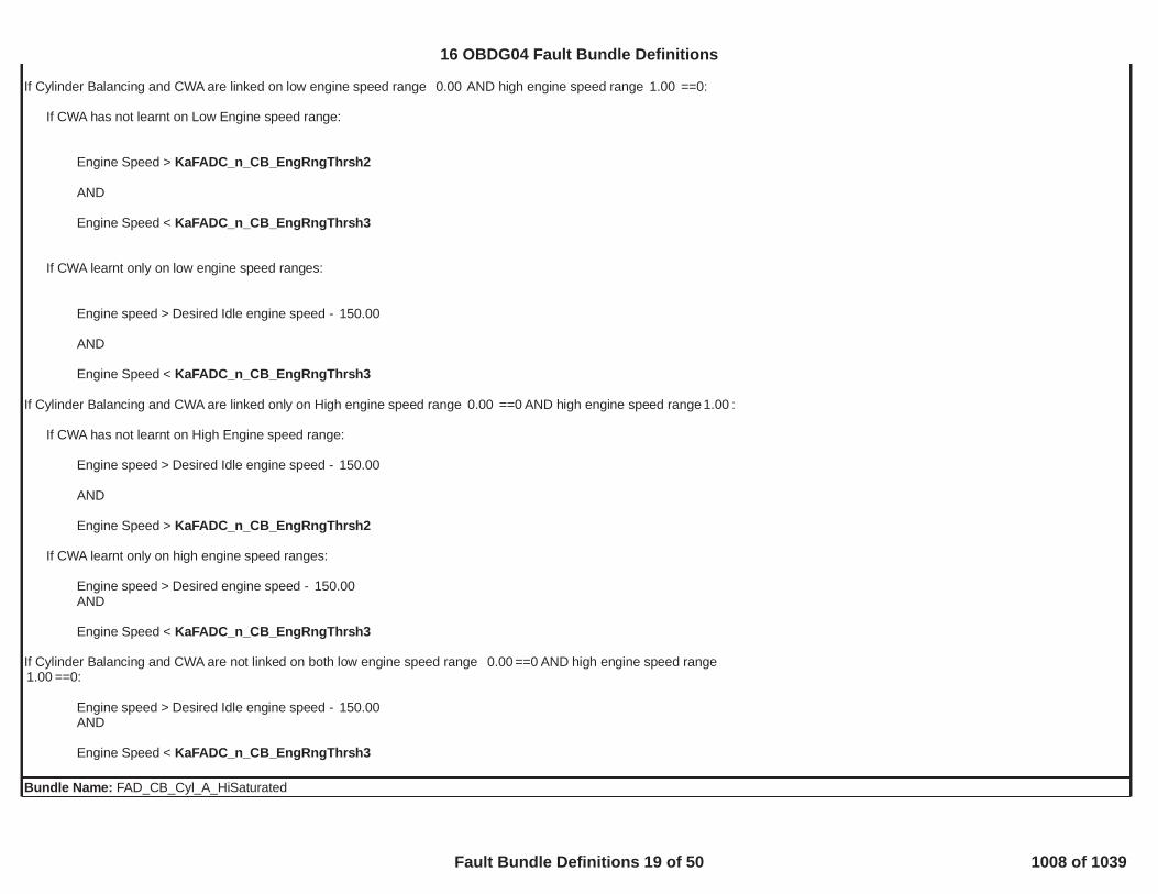
If Cylinder Balancing and CWA are linked on low engine speed range AND high engine speed range ==0:0.00 1.00
If CWA has not learnt on Low Engine speed range:
Engine Speed > KaFADC_n_CB_EngRngThrsh2
AND
Engine Speed < KaFADC_n_CB_EngRngThrsh3
If CWA learnt only on low engine speed ranges:
Engine speed > Desired Idle engine speed - 150.00
AND
Engine Speed < KaFADC_n_CB_EngRngThrsh3
If Cylinder Balancing and CWA are linked only on High engine speed range ==0 AND high engine speed range :0.00 1.00
If CWA has not learnt on High Engine speed range:
Engine speed > Desired Idle engine speed - 150.00
AND
Engine Speed > KaFADC_n_CB_EngRngThrsh2
If CWA learnt only on high engine speed ranges:
Engine speed > Desired engine speed - 150.00AND
Engine Speed < KaFADC_n_CB_EngRngThrsh3
If Cylinder Balancing and CWA are not linked on both low engine speed range ==0 AND high engine speed range0.00==0:1.00
Engine speed > Desired Idle engine speed - 150.00AND
Engine Speed < KaFADC_n_CB_EngRngThrsh3
Bundle Name: FAD_CB_Cyl_A_HiSaturated
16 OBDG04 Fault Bundle Definitions
Fault Bundle Definitions 19 of 50 1008 of 1039

FAD_CB_Cyl_A_HiSaturated - Other Definitions:If Combustion Mode == :KaFADC_b_CB_NormalCombModeCB Fuel Volume Correction applied on cylinder A > KtFADC_V_CB_CntrlLimHysteresis on positive CB Fuel Volume Correction= 0.20
If Combustion Mode != :KaFADC_b_CB_NormalCombModeCB Fuel Volume Correction applied on cylinder A > KtFADC_V_CB_CntrlLimRgntHysteresis on positive CB Fuel Volume Correction= 0.20Bundle Name: FAD_CB_Cyl_A_LoSaturated
FAD_CB_Cyl_A_LoSaturated - Other Definitions:If Combustion Mode == :KaFADC_b_CB_NormalCombModeCB Fuel Volume Correction applied on cylinder A <- KtFADC_V_CB_CntrlLimHysteresis on negative CB Fuel Volume Correction= 0.50
If Combustion Mode != :KaFADC_b_CB_NormalCombModeCB Fuel Volume Correction applied on cylinder A < -KtFADC_V_CB_CntrlLimRgntHysteresis on negative CB Fuel Volume Correction= 0.50Bundle Name: FAD_CB_Cyl_B_HiSaturated
FAD_CB_Cyl_B_HiSaturated - Other Definitions:If Combustion Mode == :KaFADC_b_CB_NormalCombModeCB Fuel Volume Correction applied on cylinder B > KtFADC_V_CB_CntrlLimHysteresis on positive CB Fuel Volume Correction= 0.20
If Combustion Mode != :KaFADC_b_CB_NormalCombModeCB Fuel Volume Correction applied on cylinder B > KtFADC_V_CB_CntrlLimRgntHysteresis on positive CB Fuel Volume Correction= 0.20Bundle Name: FAD_CB_Cyl_B_LoSaturated
FAD_CB_Cyl_B_LoSaturated - Other Definitions:If Combustion Mode == :KaFADC_b_CB_NormalCombModeCB Fuel Volume Correction applied on cylinder B <- KtFADC_V_CB_CntrlLimHysteresis on negative CB Fuel Volume Correction= 0.50
If Combustion Mode != :KaFADC_b_CB_NormalCombModeCB Fuel Volume Correction applied on cylinder B < -KtFADC_V_CB_CntrlLimRgntHysteresis on negative CB Fuel Volume Correction= 0.50Bundle Name: FAD_CB_Cyl_C_HiSaturated
FAD_CB_Cyl_C_HiSaturated - Other Definitions:If Combustion Mode == :KaFADC_b_CB_NormalCombModeCB Fuel Volume Correction applied on cylinder C > KtFADC_V_CB_CntrlLim
16 OBDG04 Fault Bundle Definitions
Fault Bundle Definitions 20 of 50 1009 of 1039

Hysteresis on positive CB Fuel Volume Correction= 0.20
If Combustion Mode != :KaFADC_b_CB_NormalCombModeCB Fuel Volume Correction applied on cylinder C > KtFADC_V_CB_CntrlLimRgntHysteresis on positive CB Fuel Volume Correction= 0.20Bundle Name: FAD_CB_Cyl_C_LoSaturated
FAD_CB_Cyl_C_LoSaturated - Other Definitions:If Combustion Mode == :KaFADC_b_CB_NormalCombModeCB Fuel Volume Correction applied on cylinder C <- KtFADC_V_CB_CntrlLimHysteresis on negative CB Fuel Volume Correction= 0.50
If Combustion Mode != :KaFADC_b_CB_NormalCombModeCB Fuel Volume Correction applied on cylinder C < -KtFADC_V_CB_CntrlLimRgntHysteresis on negative CB Fuel Volume Correction= 0.50Bundle Name: FAD_CB_Cyl_D_HiSaturated
FAD_CB_Cyl_D_HiSaturated - Other Definitions:If Combustion Mode == :KaFADC_b_CB_NormalCombModeCB Fuel Volume Correction applied on cylinder D > KtFADC_V_CB_CntrlLimHysteresis on positive CB Fuel Volume Correction= 0.20
If Combustion Mode != :KaFADC_b_CB_NormalCombModeCB Fuel Volume Correction applied on cylinder D > KtFADC_V_CB_CntrlLimRgntHysteresis on positive CB Fuel Volume Correction= 0.20Bundle Name: FAD_CB_Cyl_D_LoSaturated
FAD_CB_Cyl_D_LoSaturated - Other Definitions:If Combustion Mode == :KaFADC_b_CB_NormalCombModeCB Fuel Volume Correction applied on cylinder D <- KtFADC_V_CB_CntrlLimHysteresis on negative CB Fuel Volume Correction= 0.50
If Combustion Mode != :KaFADC_b_CB_NormalCombModeCB Fuel Volume Correction applied on cylinder D < -KtFADC_V_CB_CntrlLimRgntHysteresis on negative CB Fuel Volume Correction= 0.50Bundle Name: FAD_CB_InjStkFltP029C, P02A0, P02A4, P02A8Bundle Name: FAD_CB_MagnitudeChkFlt
FAD_CB_MagnitudeChkFlt - Other Definitions:XOY_SecurityFltBundle Name: FAD_CB_MaxAutShutOffP0263, P0266, P0269, P0272Bundle Name: FAD_CB_ShtOffReq
16 OBDG04 Fault Bundle Definitions
Fault Bundle Definitions 21 of 50 1010 of 1039

P029C, P02A0, P02A4, P02A8, P0263, P0266, P0269, P0272FAD_CB_ShtOffReq - Other Definitions:
, , , , , , ,FUL_GenericInjSysFlt FAD_CB_MagnitudeChkFlt FAD_CWA_RngShtOffReq FAD_EIA_RedntFlt FHP_HighPresSysFlt FHP_InjLeakage Transmission Estimated Gear ValidityCrankSensor_TFTKOBundle Name: FAD_CWA_RngShtOffReq
FAD_CWA_RngShtOffReq - Other Definitions:CrankSensor_TFTKOBundle Name: FAD_DFSA_EnblLrn
FAD_DFSA_EnblLrn - Other Definitions:Enabled by calibration: 1
Engine is running
FSA learning is not active: == FALSEFAD_FSA_EnblLrn
O2 sensor is fully operative: == FALSEOXY_eqr_TurbDwnNotRlb
Enabled in combustion mode: KaFADC_b_FSA_EnblCombMode
(OBD Coolant Enable Criteria == TRUEOREngine coolant temperature > [°C])45.00
Engine coolant temperature < [°C]117.00
Fuel temperature in range: > [°C]-10.00< [°C]90.00
Ambient air pressure > [kPa]67.00
Intake air temperature in range: > [°C]-7.00< [°C]78.00
No Post released
No After injection released when Boolean flag used to enable After injection check is FALSE: 0
Engine speed in range: > [rpm]700.00< [rpm]3,550.00
Equivalence Ratio in range: > [-]0.15< [-]0.85
Difference between fuel estimation and fuel injected quantity < [mm^3]64.00for a time > [s]0.00
16 OBDG04 Fault Bundle Definitions
Fault Bundle Definitions 22 of 50 1011 of 1039

Injected fuel quantity variation < [mm^3]0.17for a time > [s]0.50
Injected fuel quantity > [mm^3]2.10for a time > [s]2.00
Injected fuel quantity < [mm^3]KtFADC_V_FSA_MaxFuelFall
Engine speed variation < [rpm]KaFADC_n_DFSA_EngSpdThrshfor a time > [s]0.25
Intake air mass variation < [mg]3.00for a time > [s]0.25
No pending or confirmed DTCs: , ,FAD_FSA_LrnShtOffReq FAD_DFSA_LrnShtOffReq OXY_eqr_TurbDwn_FSA_NotVldBundle Name: FAD_DFSA_LrnShtOffReq
FAD_DFSA_LrnShtOffReq - Other Definitions:, ,EXM_TurbFlowNotValid EGP_PresTurbDwnFlt EGT_SnsrTurbDwnFlt
Bundle Name: FAD_EIA_DID_Written
FAD_EIA_DID_Written - Other Definitions:Set to TRUE if all EIA (End of line Injector Adjustment) codes have been successfully programmed via DID (DIDs $60-$64).Bundle Name: FAD_EIA_RedntFlt
FAD_EIA_RedntFlt - Other Definitions:XOY_SecurityFltBundle Name: FAD_FSA_EnblLrn
FAD_FSA_EnblLrn - Other Definitions:Enabled by calibration: 1
Engine is running
O2 sensor is fully operative: == FALSEOXY_eqr_TurbDwnNotRlb
Enabled in combustion mode: KaFADC_b_FSA_EnblCombMode
(OBD Coolant Enable Criteria == TRUEOREngine coolant temperature > [°C])45.00
Engine coolant temperature < [°C]117.00
Fuel temperature in range: > [°C]-10.00
16 OBDG04 Fault Bundle Definitions
Fault Bundle Definitions 23 of 50 1012 of 1039

< [°C]90.00
Ambient air pressure > [kPa]67.00
Intake air temperature in range: > [°C]-7.00< [°C]78.00
No Post released
No After injection released when Boolean flag used to enable After injection check is FALSE: 0
Engine speed in range: > [rpm]700.00< [rpm]3,550.00
Equivalence Ratio in range: > [-]0.15< [-]0.85
Difference between fuel estimation and fuel injected quantity < [mm^3]64.00for a time > [s]1.00
Injected fuel quantity variation < [mm^3]0.09for a time > [s]1.00
Injected fuel quantity > [mm^3]2.10for a time > [s]2.00
Injected fuel quantity < [mm^3]KtFADC_V_FSA_MaxFuelFall
Engine speed variation < [rpm]KaFADC_n_FSA_EngSpdThrshfor a time > [s]0.40
No pending or confirmed DTCs: ,FAD_FSA_LrnShtOffReq OXY_eqr_TurbDwn_FSA_NotVldBundle Name: FAD_FSA_LrnShtOffReq
FAD_FSA_LrnShtOffReq - Other Definitions:, ( AND ), ( AND ), , , ,CrankSensor_TFTKO ECT_Sensor_FA ECT_Sensor_TFTKO IAT_SensorFA IAT_SensorTFTKO FTS_FTS_CktFA FTS_FTS_PlFA AmbPresDfltdStatus, , ,FUL_GenericInjSysFlt FAD_CB_InjStkFlt FHP_InjLeakage
, ( AND )Transmission Gear Ratio Validity MAF_MAF_SnsrFA MAF_MAF_SnsrTFTKOBundle Name: FAD_FSA_NormRngCrtnValid
FAD_FSA_NormRngCrtnValid - Other Definitions:Not disabled by calibration: 0
No pending or confirmed DTCs: FAD_FSA_NormRngShtOffReq
Enabled in combustion mode = KaFADC_b_FSA_CombModeEnblRlsBundle Name: FAD_FSA_NormRngShtOffReq
16 OBDG04 Fault Bundle Definitions
Fault Bundle Definitions 24 of 50 1013 of 1039

FAD_FSA_NormRngShtOffReq - Other Definitions:, ( AND ), ( AND ),CrankSensor_TFTKO ECT_Sensor_FA ECT_Sensor_TFTKO IAT_SensorFA IAT_SensorTFTKO
, , ,FTS_FTS_CktFA FTS_FTS_PlFA AmbPresDfltdStatus FUL_GenericInjSysFltBundle Name: FAD_SQA_InjMgntEnbld
FAD_SQA_InjMgntEnbld - Other Definitions:XSQA Learning Enabled via calibration = 1.00ORSQC Enabled via calibration 1.00
Fuel Rail Discharge Request Not active FHP_FuelRailDischargeReq
Cumulative Fuel Request (Hot Chamber detection) >= [mm3]16,000.00Increased during fuel injection and decreased, based on intake manifold air flow, during diesel fuel cut-off condition.
Air actuators delay time during zero torque before enable SQA (air actuators ready) >= [s]0.50
No active DTCs:FAD_SQC_LrnShtOffReq
No Fuel Rail Setpoint limited due to fuel overtemperature FHP_SetPtLimByFuelTemp
No Fuel Injected FUL_FuelInjected
SQA rail pressure value steady state (SQA Rail Pressure Set Point +/- )KaFADC_p_SQA_LrnDeltconditions for time >= [s] (rail pressure steady-state conditions)0.20
Combustion mode = [Boolean]KaFADC_b_SQA_EnblCMBR
Engine coolant temperature > [°C] < AND < [°C]68.00 117.00Hysteresis on Engine coolant temperature = [°C]1.50
Fuel temperature > [°C]AND < [°C]0.00 70.00Hysteresis on Fuel temperature = [°C]1.00
CWA correction active in current and lower engine speed range.Checked only if SQA and CWA are linked via calibration = [boolean]0.00CWA learned in the following engine speed ranges KaFADC_b_SQC_CWA_EnblLink
Engine Speed < (Gear, Rail Pressure level) [rpm] AND > (Gear, Rail Pressure level) [rpm]KaFADC_n_SQC_HiThrsh KaFADC_n_SQC_LoThrshHysteresis on Engine Speed= [rpm]10.00
Driveline steady state condition: Time from last gear shift > [s]1.00
SQA noise check (rough road detection) not failed less than fail samples out of samples.3.00 15.00
Manifold Air Pressure (for Injection quantity and timing monitoring) < (Engine Speed) [kPa]KtFADD_p_XSQA_MAP_HiThrshHysteresis on Manifold Air Pressure Threshold (for Injection quantity and timing monitoring) = [kPa]2.00
16 OBDG04 Fault Bundle Definitions
Fault Bundle Definitions 25 of 50 1014 of 1039

ORManifold Air Pressure (for SQA Control) < (Engine Speed) [kPa]KtFADC_p_SQA_MAP_HiThrshHysteresis on Manifold Air Pressure Threshold (for SQA Control) = [kPa]2.00
No inhibit request during O2 increasing dynamic check:P013A is not in timer evaluation state (Checked only if SQA inhibit during test execution is enabled via calibration )1.00ANDP014C is not in timer evaluation state (Checked only if SQA inhibit during test execution is enabled via calibration )0.00See P013A and P014C for details.
Diesel Fuel Cut-off conditions fulfilled for time > [s]0.20ANDNo CWA, SDC or OPA learning active.
Gears: 3, 4, 5, 6
In case of automatic transmission:TCC status: Locked or Controlled slip
In case of AWD:Enabled in AWD o 2WD, not enabled with low ratio gears.Bundle Name: FAD_SQA_LrnET_Enbl
FAD_SQA_LrnET_Enbl - Other Definitions:FAD_SQA_InjMgntEnbldBundle Name: FAD_SQA_LrnPresEnbl
FAD_SQA_LrnPresEnbl - Other Definitions:XSQA Learning Enabled via calibration = 1.00
OR
SQC Enabled via calibration 1.00
Cumulative Fuel Request (Hot Chamber detection) >= [mm3]16,000.00Increased during fuel injection and decreased, based on intake manifold air flow, during diesel fuel cut-off condition.
No active DTCs: FAD_SQC_LrnShtOffReq
Combustion mode= [Boolean]KaFADC_b_SQA_EnblCMBR
Engine coolant temperature > [°C] < AND < [°C]68.00 117.00Hysteresis on Engine coolant temperature = [°C]1.50
Fuel temperature > [°C]AND < [°C]0.00 70.00Hysteresis on Fuel temperature = [°C]1.00
16 OBDG04 Fault Bundle Definitions
Fault Bundle Definitions 26 of 50 1015 of 1039

CWA correction active in current and lower engine speed range.Checked only if SQA and CWA are linked via calibration = [boolean]0.00CWA learned in the following engine speed ranges KaFADC_b_SQC_CWA_EnblLink
Engine Speed range < + [rpm] AND > [rpm]KaFADC_n_SQC_HiThrshDelt KaFADC_n_SQC_HiThrsh KaFADC_n_SQC_LoThrshHysteresis on Engine Speed= [rpm]10.00
Driveline steady state condition: Time from last gear shift > [s]1.00
Manifold Air Pressure (for Injection quantity and timing monitoring) < (Engine Speed) [kPa]KtFADD_p_XSQA_MAP_HiThrshHysteresis on Manifold Air Pressure Threshold (for Injection quantity and timing monitoring) = [kPa]2.00ORManifold Air Pressure (for SQA Control) < (Engine Speed) [kPa]KtFADC_p_SQA_MAP_HiThrshHysteresis on Manifold Air Pressure Threshold (for SQA Control) = [kPa]2.00
Diesel Fuel Cut-off conditions fulfilled for time > [s]0.20ANDNo CWA (Crank-Wheel Adaptation), SDC(Sensor Drift Compensation) or OPA(Oxygen Pressure Adaptation) learning active.
Gears: 3, 4, 5, 6
In case of automatic transmission:TCC status: Locked or Controlled slip
In case of AWD:Enabled in AWD o 2WD, not enabled with low ratio gears.Bundle Name: FAD_SQC_LrnShtOffReq
FAD_SQC_LrnShtOffReq - Other Definitions:, OR ,FAD_SQF_LrnShtOffReq FTS_FTS_CktFA FTS_FTS_PlFA FUL_InjLeakTempValid
Bundle Name: FAD_SQF_LrnShtOffReq
FAD_SQF_LrnShtOffReq - Other Definitions:, , , ,FAD_CWA_RngShtOffReq ClchPstnSnsrPerf FA ClutchPstnSnsr FA ClutchPstnSnsrCktLo FA, , , , , , , ,ClutchPstnSnsrNotLearned ClutchPstnSnsrCktHi FA CrankSensor_TFTKO SWC_SwirlShtOffReq EGR_PstnShtOffReq TPS_PstnDvtnFA FHP_InjLeakage LPE_PstnShtOffReq
, , , AND , AND ,FourWheelDriveLowStateInvalid FHP_HighPresSysFlt FUL_GenericInjSysFlt ECT_Sensor_TFTKO ECT_Sensor_FA IAT_SensorFA IAT_SensorTFTKOAND , AND , AND , ,MnfdTempSensorTFTKO MnfdTempSensorFA MAP_EngOffPressFA MAP_EngOffPressTFTKO MAP_SensorFA MAP_SensorTFTKO AmbPresDfltdStatus
Transmission Gear Ratio ValidityBundle Name: FAD_XSQA_LrnCondEnbl
FAD_XSQA_LrnCondEnbl - Other Definitions:XSQA Learning Enabled via calibration = 1.00
Fuel Rail Discharge Request Not active: FHP_FuelRailDischargeReq
Cumulative Fuel Request (Hot Chamber detection) >= [mm3]16,000.00
16 OBDG04 Fault Bundle Definitions
Fault Bundle Definitions 27 of 50 1016 of 1039

Increased during fuel injection and decreased, based on intake manifold air flow, during diesel fuel cut-off condition.
Air actuators delay time during zero torque before enable SQA (air actuators ready) >= [s]0.50
No active DTCs: FAD_SQC_LrnShtOffReq
No Fuel Rail Setpoint limited due to fuel overtemperature FHP_SetPtLimByFuelTemp
No Fuel Injected FUL_FuelInjected
SQA rail pressure value steady state (SQA Rail Pressure Set Point +/- )KaFADC_p_SQA_LrnDeltconditions for time >= [s] (rail pressure steady-state conditions)0.20
Combustion mode = [Boolean]KaFADC_b_SQA_EnblCMBR
Engine coolant temperature > [°C] < AND < [°C]68.00 117.00Hysteresis on Engine coolant temperature = [°C]1.50
Fuel temperature > [°C] AND < [°C]0.00 70.00Hysteresis on Fuel temperature = [°C]1.00
CWA correction active in current and lower engine speed range.Checked only if SQA and CWA are linked via calibration = [boolean]0.00CWA learned in the following engine speed ranges KaFADC_b_SQC_CWA_EnblLink
Engine Speed < (Gear, Rail Pressure level) [rpm] AND > (Gear, Rail Pressure level) [rpm]KaFADC_n_SQC_HiThrsh KaFADC_n_SQC_LoThrshHysteresis on Engine Speed= [rpm]10.00
Driveline steady condition: Time from last gear shift > [s].1.00
SQA noise check (rough road detection) not failed less than fail samples over samples.3.00 15.00
Manifold Air Pressure < [Engine Speed]KtFADD_p_XSQA_MAP_HiThrshHysteresis on Manifold Air Pressure Threshold = 2.00
No inhibit request during O2 increasing dynamic check:P013A is not in timer evaluation state (Checked only if SQA inhibit during test execution is enabled via calibration )1.00ANDP014C is not in timer evaluation state (Checked only if SQA inhibit during test execution is enabled via calibration )0.00See P013A and P014C for details.
Diesel Fuel Cut-off conditions fulfilled for time > [s]0.20ANDNo CWA (Crank-Wheel Adaptation), SDC (Sensor Drift Compensation) or OPA (Oxygen Pressure Adaptation) learning active.
Gears: 3, 4, 5, 6
In case of automatic transmission:TCC status: Locked or Controlled slip
16 OBDG04 Fault Bundle Definitions
Fault Bundle Definitions 28 of 50 1017 of 1039

In case of AWD:Enabled in AWD o 2WD, not enabled with low ratio gears.Bundle Name: FHP_EngineShutdownReqP0087FHP_EngineShutdownReq - Other Definitions:[ AND (P0092 OR P0090 OR P0191 OR P0194FHP_PR_CtrlModeInhb
OR P0089 OR P0193 OR P0192 OR P228A OR )]FHP_V5B_OutOfRangeFltOR [ AND (P2293 OR P228B)]FHP_MU_CtrlModeInhbBundle Name: FHP_FuelRailDischargeReq
FHP_FuelRailDischargeReq - Other Definitions:[ ( = CeFHPG_e_MU_ModeSel )Pressure Control Configuration
OR( = CeFHPG_e_MU_And_PR_ModeSel ANDPressure Control Configuration
= FALSE ANDFHP_MU_CtrlModeInhb= TRUE ) ]FHP_PR_CtrlModeInhb
AND( = TRUE ANDZeroTorq
= TRUE ANDFHP_PresOfstEngine is not required to shut off AND
= CeFULR_e_TstPhaseInit ANDFUL_IFT_StAt least one injection has been commanded since begin of driving cycle AND
= FALSE )FHP_ROD_InjActvBundle Name: FHP_HighPresSysFlt
FHP_HighPresSysFlt - Other Definitions:OR OR ORFHP_EngineShutdownReq FHP_RailPresRdctReq FHP_TorqRdctReq FHP_MU_CurrCktTFTKO
Bundle Name: FHP_InjLeakageP0087, P228B, P228AFHP_InjLeakage - Other Definitions:
Bundle Name: FHP_InjLeakageFAP0087, P228B, P228ABundle Name: FHP_MU_CtrlModeInhbP0191, P0192, P0193, P0194, P0089, P0090, P0091, P0092, P228A, P0089,FHP_MU_CtrlModeInhb - Other Definitions:[P228D AND NOT(P229B)] OR
= 0 ORMetering Unit Valve presentFHP_V5B_OutOfRangeFltBundle Name: FHP_MU_CurrCktTFTKOP163ABundle Name: FHP_MU_DrvrCloseTFTKO
16 OBDG04 Fault Bundle Definitions
Fault Bundle Definitions 29 of 50 1018 of 1039

P0091Bundle Name: FHP_MU_DrvrOpenTFTKOP0090, P0092Bundle Name: FHP_NoRailDischarge
FHP_NoRailDischarge - Other Definitions:If { [ ( Fuel temperature > °C) OR ] AND ( OR ) } then63.0 FTS_FTS_Flt ZeroTorqPrdtdActv ZeroTorq
( Rail pressure setpoint gradient MPa for at least * 6.25 ms )-1.00 100Else
( = FALSE AND = FALSE )ZeroTorqPrdtdActv ZeroTorqBundle Name: FHP_PR_CtrlModeInhbP2293, P229B, P2294, P2295, P2296FHP_PR_CtrlModeInhb - Other Definitions:[NOT(P228D) AND P229B] OR
= 0Pressure Regulator Valve presentBundle Name: FHP_PR_DrvrCloseTFTKOP2295Bundle Name: FHP_PR_DrvrOpenTFTKOP2294, P2296Bundle Name: FHP_PR_FuelTempLimEnbl
FHP_PR_FuelTempLimEnbl - Other Definitions:Rail pressure setpoint > Rail Pressure limitation for Pressure RegulatorBundle Name: FHP_PresGovnSelStRefer to RailPresCntrl section.Bundle Name: FHP_PresGovnStRefer to RailPresCntrl section.Bundle Name: FHP_PresOfst
FHP_PresOfst - Other Definitions:Rail pressure setpoint - Rail pressure < 0 MPa ANDABS(Rail pressure setpoint - Rail pressure) > MPa for * 6.25 ms4.0 20Bundle Name: FHP_PresStdySt
FHP_PresStdySt - Other Definitions:ABS(Rail pressure setpoint - Rail pressure) < MPa for * 6.25 ms2.9 65Bundle Name: FHP_RailPresRdctReqP1297, P228C, P229AFHP_RailPresRdctReq - Other Definitions:[ AND (P2293 OR P228D OR P229B OR P0092 OR P0090 OR P000F OR P0088 OR P0089 OR P228B)]FHP_PR_CtrlModeInhbOR
16 OBDG04 Fault Bundle Definitions
Fault Bundle Definitions 30 of 50 1019 of 1039

[ AND (P228D OR P0092 OR P0090 OR P0191 OR P0194 OR P0089 OR P0193 OR P0192 OR P228A OR )]FHP_MU_CtrlModeInhb FHP_V5B_OutOfRangeFltBundle Name: FHP_ROD_InjActv
FHP_ROD_InjActv - Other Definitions:FalseBundle Name: FHP_RPS_CktFAP0192, P0193Bundle Name: FHP_RPS_CktTFTKOP0192, P0193Bundle Name: FHP_RPS_FltP0191, P0192, P0193, P0194FHP_RPS_Flt - Other Definitions:FHP_V5B_OutOfRangeFltBundle Name: FHP_RPS_OfstTFTKOP0191Bundle Name: FHP_SetPtLimByFuelTemp
FHP_SetPtLimByFuelTemp - Other Definitions:Rail pressure setpoint > Rail Pressure Setpoint limitationBundle Name: FHP_TorqRdctReqP1297FHP_TorqRdctReq - Other Definitions:[ AND (P2293 OR P228D OR P229B OR P0092 OR P0090 OR P000F OR P0088 OR P0089 OR P228B)]FHP_PR_CtrlModeInhbOR
[ AND (P228D OR P229B OR P0092 OR P0090 OR P0191 OR P0194 OR P0089 OR P0193 OR P0192 OR OR P228A)]FHP_MU_CtrlModeInhb FHP_V5B_OutOfRangeFltBundle Name: FHP_V5B_OutOfRangeFlt
FHP_V5B_OutOfRangeFlt - Other Definitions:5VoltReferenceB_FABundle Name: FourWheelDriveLowStateInvalidP2771Bundle Name: FTS_FTS_CktFAP0182, P0183Bundle Name: FTS_FTS_Flt
FTS_FTS_Flt - Other Definitions:ORFTS_FTS_CktFA FTS_FTS_PlFA
Bundle Name: FTS_FTS_PlFAP0181Bundle Name: FTS_PlausRefSnsrFlt
16 OBDG04 Fault Bundle Definitions
Fault Bundle Definitions 31 of 50 1020 of 1039

FTS_PlausRefSnsrFlt - Other Definitions:if is equal to CeFTSR_e_ECT_Snsr;ECT_Sensor_FA P0181 Fuel Temperature Sensor Reference
if is equal to CeFTSR_e_IAT_Snsr;IAT_SensorFA P0181 Fuel Temperature Sensor Referenceif is equal to CeFTSR_e_IAT_2_Snsr;MnfdTempSensorFA P0181 Fuel Temperature Sensor Reference
if is equal to CeFTSR_e_MainCatTempSnsr.EGT_SnsrDPF_UpFA P0181 Fuel Temperature Sensor ReferenceBundle Name: FuelLevelDataFaultP0461, P0462, P0463, P2066, P2067, P2068FuelLevelDataFault - Other Definitions:AccCktLo_FABundle Name: FUL_BoostVoltTFTKOP062DBundle Name: FUL_CntrlrStTFTKOP062BBundle Name: FUL_CylDisable_CiEPSR_CylinderA
FUL_CylDisable_CiEPSR_CylinderA - Other Definitions:Injector 1 disabled by CPID $18 (AE 18 80 80) (Injector Disable Test strategy only active at Service)Bundle Name: FUL_CylDisable_CiEPSR_CylinderB
FUL_CylDisable_CiEPSR_CylinderB - Other Definitions:Injector 3 disabled by CPID $18 (AE 18 80 40) (Injector Disable Test strategy only active at Service)Bundle Name: FUL_CylDisable_CiEPSR_CylinderC
FUL_CylDisable_CiEPSR_CylinderC - Other Definitions:Injector 4 disabled by CPID $18 (AE 18 80 20) (Injector Disable Test strategy only active at Service)Bundle Name: FUL_CylDisable_CiEPSR_CylinderD
FUL_CylDisable_CiEPSR_CylinderD - Other Definitions:Injector 2 disabled by CPID $18 (AE 18 80 10) (Injector Disable Test strategy only active at Service)Bundle Name: FUL_CylInjCktTFTKO_CiEPSR_CylinderAP2147, P2148, P0261, P0262, P0201, P1248, P0271, P0270Bundle Name: FUL_CylInjCktTFTKO_CiEPSR_CylinderBP2150, P2151, P0267, P0268, P0203, P124A, P0264, P0265Bundle Name: FUL_CylInjCktTFTKO_CiEPSR_CylinderCP2147, P2148, P0270, P0271, P0204, P124B, P0261, P0262Bundle Name: FUL_CylInjCktTFTKO_CiEPSR_CylinderDP2150, P2151, P0264, P0265, P0202, P1249, P0267, P0268Bundle Name: FUL_FuelInjected
16 OBDG04 Fault Bundle Definitions
Fault Bundle Definitions 32 of 50 1021 of 1039

FUL_FuelInjected - Other Definitions:At least one Injection Pulse is requested by the application software (engine running and no cut off active)Bundle Name: FUL_FuelInjectedCyl_CiEPSR_CylinderA
FUL_FuelInjectedCyl_CiEPSR_CylinderA - Other Definitions:At least one Injection Pulse is requested by the application software for the cylinder 1 (engine running and no cut off active)Bundle Name: FUL_FuelInjectedCyl_CiEPSR_CylinderB
FUL_FuelInjectedCyl_CiEPSR_CylinderB - Other Definitions:At least one Injection Pulse is requested by the application software for the cylinder 3 (engine running and no cut off active)Bundle Name: FUL_FuelInjectedCyl_CiEPSR_CylinderC
FUL_FuelInjectedCyl_CiEPSR_CylinderC - Other Definitions:At least one Injection Pulse is requested by the application software for the cylinder 4 (engine running and no cut off active)Bundle Name: FUL_FuelInjectedCyl_CiEPSR_CylinderD
FUL_FuelInjectedCyl_CiEPSR_CylinderD - Other Definitions:At least one Injection Pulse is requested by the application software for the cylinder 2 (engine running and no cut off active)Bundle Name: FUL_GenericInjSysFAP2147, P2148, P2150, P2151, P0261, P0262, P0264, P0265, P0267, P0268, P0270, P0271, P0201, P0202, P0203, P0204, P1248, P1249, P124A, P124B,P062B, P062D, P0216, P126A, P02EE, P02EF, P02F0, P02F1, P020A, P020B, P020C, P020DBundle Name: FUL_GenericInjSysFltP2147, P2148, P2150, P2151, P0261, P0262, P0264, P0265, P0267, P0268, P0270, P0271, P0201, P0202, P0203, P0204, P1248, P1249, P124A, P124B,P062B, P062D, P0216, P126A, P02EE, P02EF, P02F0, P02F1, P020A, P020B, P020C, P020DBundle Name: FUL_IFT_St
FUL_IFT_St - Other Definitions:This interface can assume the following values when the CPID related to the Injetor Flow Test is triggered (AE 22 04)- CeFULR_e_TstPhaseInit: default status (CDIP not requested or abort reason evaluation in progress)- CeFULR_e_IFT_PresSetPtReq:- CeFULR_e_InjFlowPumpDisablePh1,- CeFULR_e_InjFlowPumpDisablePh2,- CeFULR_e_PostTstPhase,- CeFULR_e_InterTstPrd
Due to the fact that this CPID is not calibrated, the status of this interface is always CeFULR_e_TstPhaseInit.Bundle Name: FUL_InjCktTFTKOP2147, P2148, P2150, P2151, P0261, P0262, P0264, P0265, P0267, P0268, P0270, P0271, P0201, P0202, P0203, P0204, P1248, P1249, P124A, P124B,
Bundle Name: FUL_InjectorDisable
FUL_InjectorDisable - Other Definitions:
16 OBDG04 Fault Bundle Definitions
Fault Bundle Definitions 33 of 50 1022 of 1039

device control active (AE 18 80 XX)ANDXX refers to a valid cylinder (1 - 4)ANDIFT not active ( == CeFULR_e_TstPhaseInit)FUL_IFT_StANDdevice control timer > 0 sec
When the test is in progress, the injector is disabled for a fixed time (about 30s). The device control timer starts from this fixed time and it is decreased up to 0 s.Bundle Name: FUL_InjLeakInitNotValid
FUL_InjLeakInitNotValid - Other Definitions:This flag is TRUE when the following conditions are verified in AND:
engine synchronized, i.e.(GetEPSR_e_EngSyncState() == CeEPSR_EngineSync) ||
(GetEPSR_e_EngSyncState() == CeEPSR_BackupSync) || (GetEPSR_e_EngSyncState()== CeEPSR_e_VerifySync)
AND
( || )IAT_SensorTFTKO EngineModeNotRunTimerErrorBundle Name: FUL_InjLeakTempValid
FUL_InjLeakTempValid - Other Definitions:NOT( OR OR OR ORFUL_InjLeakInitNotValid ECT_Sensor_FA FTS_FTS_CktFA FTS_FTS_PlFA
OR )XOY_SecurityFlt_CeXOYR_e_FULR_FTD_RateLimFlt XOY_SecurityFlt_CeXOYR_e_ETMR_FTD_RedntCalcFltBundle Name: FUL_OutEnblCyl_CiEPSR_CylinderA
FUL_OutEnblCyl_CiEPSR_CylinderA - Other Definitions:|| || || || (Injection controller status reported by HWIO ~=0.00 FUL_CylInjCktTFTKO_CiEPSR_CylinderA FUL_PullInErrTFTKO_CeDFIR_e_Cyl1InjTmng FUL_CylDisable_CiEPSR_CylinderA
READY)Bundle Name: FUL_OutEnblCyl_CiEPSR_CylinderB
FUL_OutEnblCyl_CiEPSR_CylinderB - Other Definitions:|| || || || (Injection controller status reported by HWIO0.00 FUL_CylInjCktTFTKO_CiEPSR_CylinderB FUL_PullInErrTFTKO_CeDFIR_e_Cyl3InjTmng FUL_CylDisable_CiEPSR_CylinderB
~= READY)Bundle Name: FUL_OutEnblCyl_CiEPSR_CylinderC
FUL_OutEnblCyl_CiEPSR_CylinderC - Other Definitions:|| || || || (Injection controller status reported by HWIO0.00 FUL_CylInjCktTFTKO_CiEPSR_CylinderC FUL_PullInErrTFTKO_CeDFIR_e_Cyl4InjTmng FUL_CylDisable_CiEPSR_CylinderC
~= READY)Bundle Name: FUL_OutEnblCyl_CiEPSR_CylinderD
16 OBDG04 Fault Bundle Definitions
Fault Bundle Definitions 34 of 50 1023 of 1039

FUL_OutEnblCyl_CiEPSR_CylinderD - Other Definitions:|| || || || (Injection controller status reported by HWIO0.00 FUL_CylInjCktTFTKO_CiEPSR_CylinderD FUL_PullInErrTFTKO_CeDFIR_e_Cyl2InjTmng FUL_CylDisable_CiEPSR_CylinderD
~= READY)Bundle Name: FUL_PostEnbl
FUL_PostEnbl - Other Definitions:This flag is TRUE when the following conditions are verified in AND:
no combustion mode transition(i.e. GetCMBR_e_CombModeSec() == GetCMBR_e_CombMode())
AND
NOT( )HCI_DeHC_ExhInjDsbl
AND
(GetCMBR_e_CombModeSec() equal to one of the combustion modeCeCMBR_e_DPF_HiO2CeCMBR_e_DPF_LoO2CeCMBR_e_DPF_EngPrtct_HiO2CeCMBR_e_DPF_EngPrtct_LoO2CeCMBR_e_LNT_DeSOx_LeanCeCMBR_e_LNT_EngPrtctCeCMBR_e_DPF_PN )
AND
(
Temperature sensor > 150.00AND
== FALSE0.00
OR
Temperature sensor > 150.00AND
== TRUE0.00AND(post injection enebled during zero-torque condition for a continuous time <= [s])30.00POST injection timer is incemented only when the post injections are enabled during zero-torque condition ( == TRUE) with a delay time equal to secondsZeroTorqRefActv 0.50
for the transition from zero-torque condition off to on, and equal to seconds for the transition from zero-torque condition on to off5.00)
The temperature sensor to consider depends on the exhaust layout configuration.If == CeEXCR_e_C_UI_SCR_HCI_C_DPFCeEXCR_e_C_UI_SCR_HCI_C_DPF
16 OBDG04 Fault Bundle Definitions
Fault Bundle Definitions 35 of 50 1024 of 1039

Temperature sensor IS Catalyst 1 downstream temperature sensor (EGT2)else
Temperature sensor IS DPF up temperature sensorBundle Name: FUL_PullInErrTFTKO_CeDFIR_e_Cyl1InjTmngP020ABundle Name: FUL_PullInErrTFTKO_CeDFIR_e_Cyl2InjTmngP020BBundle Name: FUL_PullInErrTFTKO_CeDFIR_e_Cyl3InjTmngP020CBundle Name: FUL_PullInErrTFTKO_CeDFIR_e_Cyl4InjTmngP020DBundle Name: GLO_GlowPlugSplyVoltCktTFTKOP161EBundle Name: HCI_DeHC_BasicReq
HCI_DeHC_BasicReq - Other Definitions:Boolean flag indicating that DeHC is needed due to high HC storage in exhaust devices or due to not completed DeHC event.Bundle Name: HCI_DeHC_ExhInjDsbl
HCI_DeHC_ExhInjDsbl - Other Definitions:GetHCIR_b_DeHC_ExhInjDsbl =1 means that the actuators used to inject HC in the exhaust line (Post Injection and HC Injector) shall be disabled.GetHCIR_b_DeHC_ExhInjDsbl = 1 if one of those two sets of conditions is satisfied:- Combustion Mode equal to one of allowed modes (DPF), aftertreatment HC storage based request of DeHC, = 1 and none amongHCI_DeHC_BasicReq EXM_PM_TurbFlowNotVld(Exhaust Mass Flow Fault Flag), (O2 Exhaust Manifold Concentration Fault Flag) and (HC Exhaust Manifold Mass Flow Fault Flag) =EXM_O2_ExhMnfdNotValid EXM_HC_TurbFlowNotValid1.- Generic DeHC Park or DeHC Drive request is = 1, none of , and = 1 and no DeHC deactivation request forEXM_TurbFlowNotValid EXM_O2_ExhMnfdNotValid EXM_HC_TurbFlowNotValidtime or over temperature is present.Bundle Name: HCI_GenericShtOffReqP20CB, P20CD, P20CE, P2670HCI_GenericShtOffReq - Other Definitions:
Bundle Name: HCI_HC_dm_DPF_UpFlt
HCI_HC_dm_DPF_UpFlt - Other Definitions:CAT_HC_Cat2_DwnFltBundle Name: HCI_HC_dm_SCR_UpFlt
HCI_HC_dm_SCR_UpFlt - Other Definitions:EPM_HC_dm_Pipe2_DwnFltBundle Name: HCI_HCI_CntrlEnbl
16 OBDG04 Fault Bundle Definitions
Fault Bundle Definitions 36 of 50 1025 of 1039

HCI_HCI_CntrlEnbl - Other Definitions:GetHCIR_b_HCI_CntrlEnbl =1 when the control of HC Injector for regeneration purposes is enabled. GetHCIR_b_HCI_CntrlEnbl = 1 if:- Combustion Mode equal to one of allowed modes (DPF)- = 0HCI_GenericShtOffReq- = 1EXC_HCI_Enbl- = 0HCI_DeHC_ExhInjDsbl- Sensor DPF Up Temperature is higher than (with hysteresis threshold ) and = 0 or =1 and modelled DPF Up Temperature280.00 260.00 EGT_SnsrDPF_UpFlt EGT_SnsrDPF_UpFltrespects the same thresholds mentioned before.- modelled DOC 2 Up Temperature is higher than (with hysteresis threshold ) or = 1300.00 250.00 EGT_TempCat2_UpFlt- PT Relè Voltage is in the range between (with hysteresis threshold ) and (with hysteresis threshold )100,000.00 100,000.00 6.00 6.00- Differential Pressure Across HC Injector is higher than (with hysteresis threshold ) or = 1320.00 300.00 EGP_PresHCI_UpFlt- Estimated Exhaust Mass Flow Upstream HC Injector (low pass filtered with constant) is higher than (with hysteresis threshold ) and = 01.00 5.00 4.50 EXF_TotExhHC_InjUpFltBundle Name: HCI_HCI_RelRgn
HCI_HCI_RelRgn - Other Definitions:GetHCIR_b_HCI_RelRgn = 1 when the low level logic of HC Injector for Regeneration purpose is enabled that means if:- = 1HCI_HCI_CntrlEnbl- Requested HC Injector Quantity is higher than (with hysteresis threshold )2.00 1.00Bundle Name: HCI_InjReleaseSt
HCI_InjReleaseSt - Other Definitions:GetHCIR_b_InjReleaseSt = 1 if:- if = 1HCI_HCI_RelRgn- if the current 100 ms task allows the injection, according to injection frequency- if the requested HC quantity (equal to the currently requested quantity plus the integral of the quantity requested but not yet released) is greater than minimum quantity per task 67.00Bundle Name: HCI_TotExh_dm_HCI_DwnFA
HCI_TotExh_dm_HCI_DwnFA - Other Definitions:EXF_TotExhHC_InjUpFABundle Name: HCI_TotExh_dm_HCI_DwnFlt
HCI_TotExh_dm_HCI_DwnFlt - Other Definitions:EXF_TotExhHC_InjUpFltBundle Name: HumidityFAP0097, P0098, P00F4, P00F5, P2227, P2228, P2229, P2230Bundle Name: HumidityTFTKOP0097, P0098, P00F4, P00F5, P2227, P2228, P2229, P2230Bundle Name: HumTempSnsrCktFAP0097, P0098Bundle Name: HumTempSnsrFAP0096, P0097, P0098, P0099Bundle Name: HumTempSnsrTFTKO
16 OBDG04 Fault Bundle Definitions
Fault Bundle Definitions 37 of 50 1026 of 1039

P0096, P0097, P0098, P0099Bundle Name: IAT_SensorCircuitFAP0112, P0113Bundle Name: IAT_SensorFAP0111, P0112, P0113, P0114Bundle Name: IAT_SensorTFTKOP0111, P0112, P0113, P0114Bundle Name: INM_ComprAirFlowNotVld
INM_ComprAirFlowNotVld - Other Definitions:, ,MAF_MAF_SnsrFA MAF_MAF_SnsrTFTKO LPE_VlvAirFlowNotVld
Bundle Name: INM_CylTotFlowNomNotVld
INM_CylTotFlowNomNotVld - Other Definitions:, , , , , , , ,MAP_SensorFA MAP_EngOffPressFA MAP_SensorTFTKO MAP_EngOffPressTFTKO MnfdTempSensorFA MnfdTempSensorTFTKO ECT_Sensor_FA ECT_Sensor_TFTKO
,SWC_SwirlShtOffReq FUL_GenericInjSysFltBundle Name: INM_CylTotFlowNotValid
INM_CylTotFlowNotValid - Other Definitions:, ,INM_IntkGapNotValid EGR_PstnSnsrFlt LPE_PstnSnsrFlt
Bundle Name: INM_EGR_RateNotVld
INM_EGR_RateNotVld - Other Definitions:, ,INM_EGR_RateNotVld LPE_VlvTotFlowNotVld EGR_VlvTotFlowNotValid
Bundle Name: INM_IntkGapNotValid
INM_IntkGapNotValid - Other Definitions:, , ,MAF_MAF_SnsrFA MAF_MAF_SnsrTFTKO INM_CylTotFlowNomNotVld LPE_VlvTotFlowNomNotVld
Bundle Name: INM_O2_IntkMnfdNotValid
INM_O2_IntkMnfdNotValid - Other Definitions:, ,INM_CylTotFlowNotValid EGR_VlvTotFlowNotValid INM_ThrotAirFlowNotVld
Bundle Name: INM_ThrotAirFlowNotVld
INM_ThrotAirFlowNotVld - Other Definitions:INM_ComprAirFlowNotVldBundle Name: LowFuelConditionDiagnostic
LowFuelConditionDiagnostic - Other Definitions:Flag set to TRUE if the fuel level < % AND10.0
16 OBDG04 Fault Bundle Definitions
Fault Bundle Definitions 38 of 50 1027 of 1039

No Active DTCs: FuelLevelDataFault, P0462, P0463 for at least seconds30.0Bundle Name: LPE_PstnShtOffReqP044C, P044D, P045A, P045C, P045E, P045F, P045D, P049E, P1419, P141A, P141B, P141CLPE_PstnShtOffReq - Other Definitions:Stubbed to FALSE in OBDII MY16 applicationsBundle Name: LPE_PstnSnsrFltP044C, P044D, P049ELPE_PstnSnsrFlt - Other Definitions:Stubbed to FALSE in OBDII MY16 applicationsBundle Name: LPE_VlvTotFlowNomNotVld
LPE_VlvTotFlowNomNotVld - Other Definitions:Stubbed to FALSE in OBDII MY16 applicationsBundle Name: LPE_VlvTotFlowNotVld
LPE_VlvTotFlowNotVld - Other Definitions:Stubbed to FALSE in OBDII MY16 applicationsBundle Name: MAF_AirFlowEstdSS_NotVld
MAF_AirFlowEstdSS_NotVld - Other Definitions:, , , , , , , ,MAP_SensorFA MAP_SensorTFTKO MAP_EngOffPressFA MAP_EngOffPressTFTKO MnfdTempSensorFA MnfdTempSensorTFTKO ECT_Sensor_FA ECT_Sensor_TFTKO
,SWC_SwirlShtOffReq FUL_GenericInjSysFltBundle Name: MAF_MAF_SnsrCktOffstFAP0102, P0100, P0103Bundle Name: MAF_MAF_SnsrCktOffstTFKOP0102, P0100, P0103Bundle Name: MAF_MAF_SnsrFAP0100, P0101, P0102, P0103Bundle Name: MAF_MAF_SnsrTFTKOP0100, P0101, P0102, P0103Bundle Name: MAF_SensorFAP0101, P0102, P0103, P010B, P010C, P010DBundle Name: MAF_SensorTFTKOP0101, P0102, P0103, P010B, P010C, P010DBundle Name: MAP_EngOffPressFAP00C7Bundle Name: MAP_EngOffPressTFTKOP00C7Bundle Name: MAP_SensorCircuitFA
16 OBDG04 Fault Bundle Definitions
Fault Bundle Definitions 39 of 50 1028 of 1039

P0107, P0108Bundle Name: MAP_SensorCircuitFPP0107, P0108Bundle Name: MAP_SensorFAP0106, P0107, P0108Bundle Name: MAP_SensorTFTKOP0106, P0107, P0108Bundle Name: Maximum fuel flow deliverable by high pressure pumpRefer to RailPresCntrl section.Bundle Name: Metering Unit controlled in closed loopRefer to RailPresCntrl section.Bundle Name: MnfdTempSensorCktFATurbocharged or Supercharged, with Humidity sensor: P00EA, P00EB. Turbocharged or Supercharged, without Humidity sensor: P0097, P0098. Naturally Aspirated: P0112, P0113.Bundle Name: MnfdTempSensorFATurbocharged or Supercharged, with Humidity sensor: P00E9, P00EA, P00EB, P00EC. Turbocharged or Supercharged, without Humidity sensor: P0096, P0097, P0098, P0099.Naturally Aspirated: P0111, P0112, P0113, P0114.Bundle Name: MnfdTempSensorTFTKOTurbocharged or Supercharged, with Humidity sensor: P00E9, P00EA, P00EB, P00EC. Turbocharged or Supercharged, without Humidity sensor: P0096, P0097, P0098, P0099.Naturally Aspirated: P0111, P0112, P0113, P0114.Bundle Name: NOX_NOx_Rat_SCR_UpFlt
NOX_NOx_Rat_SCR_UpFlt - Other Definitions:EPM_NOx_Rat_Pipe2_DwnFltBundle Name: NOX_NOx_SnsrSCR_DwnFltU029E,NOX_NOx_SnsrSCR_DwnFlt - Other Definitions:NOX_Snsr2_NOx_FltBundle Name: NOX_NOx1_DecrDynChkFltP22FANOX_NOx1_DecrDynChkFlt - Other Definitions:
Bundle Name: NOX_NOx1_IncrDynChkFltP22F9Bundle Name: NOX_NOx1_NOxPlausFltP11CCBundle Name: NOX_NOx1_OutOfRngHiFltP2203Bundle Name: NOX_NOx1_OutOfRngLoFltP2202
16 OBDG04 Fault Bundle Definitions
Fault Bundle Definitions 40 of 50 1029 of 1039

Bundle Name: NOX_NOx1_StBitChkFltP11DBBundle Name: NOX_NOx2_DynChkFltP229FBundle Name: NOX_NOx2_OutOfRngHiFltP22A1Bundle Name: NOX_NOx2_OutOfRngLoFltP22A0Bundle Name: NOX_NOx2_StBitChkFltP11DCBundle Name: NOX_NOx2SelfDiagFltP22FEBundle Name: NOX_Snsr1_ElecFAP2205, P2209, P11DD, P2200, P220A, P115E, P115F, P1160, P116A, P116B, P116C, P116D, P116E, P116F, P1192, P1193, P1194, P2205, P2206, P2207,P2208, P2210, P2211, P11C5, P11C6, P119A, P119B, P119C
Bundle Name: NOX_Snsr1_FAP11CC, U029DNOX_Snsr1_FA - Other Definitions:NOX_Snsr1_ElecFABundle Name: NOX_Snsr1_FltStP2205, P2209, P11DD, P2200, P220A, P115E, P115F, P1160, P116A, P116B, P116C, P116D, P116E, P116F, P1192, P1193, P1194, P2205, P2206, P2207,P2208, P2210, P2211, P11C5, P11C6, P119A, P119B, P119C
Bundle Name: NOX_Snsr1_NotVldU029DNOX_Snsr1_NotVld - Other Definitions:
, ,NOX_Snsr1_FltSt NOX_NOx1_StBitChkFltBundle Name: NOX_Snsr1_NOx_Flt
NOX_Snsr1_NOx_Flt - Other Definitions:, , , , ,NOX_Snsr1_NotVld NOX_NOx1_NOxPlausFlt NOX_NOx2_OutOfRngLoFlt NOX_NOx2_OutOfRngHiFlt NOX_NOx1_DecrDynChkFlt NOX_NOx1_IncrDynChkFlt
Bundle Name: NOX_Snsr1_O2_NotRlb
NOX_Snsr1_O2_NotRlb - Other Definitions:NOx Sensor 1 supply in range > 10,8VNOx Sensor 1 dewpoint is reached = TRUE- < (sensor heater raw resistance - sensor heater target resistance) / sensor heater target resistence < +0.03 0.03Stability flag for NOx/Lambda = TRUEBundle Name: NOX_Snsr1_PresFlt
NOX_Snsr1_PresFlt - Other Definitions:
16 OBDG04 Fault Bundle Definitions
Fault Bundle Definitions 41 of 50 1030 of 1039

EGP_PresCatUpFltBundle Name: NOX_Snsr2_ElecFAP22A3, P22A7, P11DE, P229E, P220B, P11BE, P11BF, P11C0, P11D0, P11D1, P11D2, P11D8, P11D9, P11DA, P11FC, P11FD, P11FE, P22A3, P22A4, P22A5,P22A6, P22A8, P22A9, P11C7, P11C8, P119D, P119E, P119F
Bundle Name: NOX_Snsr2_FltStP22A3, P22A7, P11DE, P229E, P220B, P11BE, P11BF, P11C0, P11D0, P11D1, P11D2, P11D8, P11D9, P11DA, P11FC, P11FD, P11FE, P22A3, P22A4, P22A5,P22A6, P22A8, P22A9, P11C7, P11C8, P119D, P119E, P119F
Bundle Name: NOX_Snsr2_NotVldU029ENOX_Snsr2_NotVld - Other Definitions:
, ,NOX_Snsr2_FltSt NOX_NOx2_StBitChkFltBundle Name: NOX_Snsr2_NOx_Flt
NOX_Snsr2_NOx_Flt - Other Definitions:, , , ,NOX_Snsr2_NotVld NOX_NOx2_DynChkFlt NOX_NOx2_OutOfRngLoFlt NOX_NOx2_OutOfRngHiFlt NOX_NOx2SelfDiagFlt
Bundle Name: NOX_Snsr2_O2_NotRlb
NOX_Snsr2_O2_NotRlb - Other Definitions:NOx Sensor 2 supply in range > 10,8VNox Sensor 2 dewpoint is reached = TRUE- < (sensor heater raw resistance - sensor heater target resistance) / sensor heater target resistence < +0.03 0.03Stability flag for NOx/Lambda = TRUEBundle Name: NOX_Snsr2_PresFlt
NOX_Snsr2_PresFlt - Other Definitions:EGP_PresSCR_DwnFltBundle Name: OAT_OAT_SensorTFTKOP0071, P0072, P0073, P0074Bundle Name: OAT_OAT_SnsrNonEmissFAP0070, P0071Bundle Name: OAT_PtEstFiltFAECM OAT: P0071, P0072, P0073, P0074, EngModeNotRunTmErr, VehicleSpeedSensor_FA, IAT_SensorFA, ECT_Sensor_DefaultDetected, MAF_SensorFA. VIMC OAT: P0072,P0073, EngModeNotRunTmErr, VehicleSpeedSensor_FA, ECT_Sensor_DefaultDetected. IAT-Based OAT: VehicleSpeedSensor_FA, IAT_SensorFA, MAF_SensorFA. All other cases:EngModeNotRunTmErr, VehicleSpeedSensor_FA, IAT_SensorFA, ECT_Sensor_DefaultDetected.Bundle Name: OAT_PtEstRawFAECM OAT: P0071, P0072, P0073, P0074. VIMC OAT: P0071, P0072, P0073, EngModeNotRunTmErr, VehicleSpeedSensor_FA, ECT_Sensor_DefaultDetected. IAT-Based OAT:IAT_SensorFA. All other cases: IAT_SensorFA, ECT_Sensor_DefaultDetected.Bundle Name: OXY_eqr_TurbDwn_FSA_NotVld
OXY_eqr_TurbDwn_FSA_NotVld - Other Definitions:OXY_NOx1_eqr_FSA_NotVld
16 OBDG04 Fault Bundle Definitions
Fault Bundle Definitions 42 of 50 1031 of 1039

Bundle Name: OXY_eqr_TurbDwnNotRlb
OXY_eqr_TurbDwnNotRlb - Other Definitions:OXY_NOx1_O2_RawNotRlbBundle Name: OXY_eqr_TurbDwnNotVld
OXY_eqr_TurbDwnNotVld - Other Definitions:OXY_NOx1_EQR_NotVldBundle Name: OXY_NOx1_eqr_FSA_NotVld
OXY_NOx1_eqr_FSA_NotVld - Other Definitions:, , , , , ,NOX_Snsr1_NotVld NOX_Snsr1_PresFlt OXY_NOx1SignRngMinTFTKO OXY_NOx1SignRngMaxTFTKO OXY_NOx1ChkOvrrnTFTKO OXY_NOx1DecrDynTFTKO
OXY_NOx1IncrDynTFTKOBundle Name: OXY_NOx1_EQR_NotVld
OXY_NOx1_EQR_NotVld - Other Definitions:, , , ,NOX_Snsr1_NotVld NOX_Snsr1_PresFlt OXY_NOx1SignRngMinTFTKO OXY_NOx1SignRngMaxTFTKO
, , ,OXY_NOx1ChkOvrrnTFTKO OXY_NOx1ChkLoadTFTKO OXY_NOx1DecrDynTFTKO OXY_NOx1IncrDynTFTKOBundle Name: OXY_NOx1_O2_Flt
OXY_NOx1_O2_Flt - Other Definitions:, , , , , , ,NOX_Snsr1_NotVld NOX_Snsr1_PresFlt OXY_NOx1SignRngMinFlt OXY_NOx1SignRngMaxFlt OXY_NOx1ChkOvrrnFlt OXY_NOx1ChkLoadFlt OXY_NOx1DecrDynFlt
OXY_NOx1IncrDynFltBundle Name: OXY_NOx1_O2_RawNotRlb
OXY_NOx1_O2_RawNotRlb - Other Definitions:NOX_Snsr1_O2_NotRlbBundle Name: OXY_NOx1ChkLoadFltP2A00Bundle Name: OXY_NOx1ChkLoadTFTKOP2A00Bundle Name: OXY_NOx1ChkOvrrnFltP2297Bundle Name: OXY_NOx1ChkOvrrnTFTKOP2297Bundle Name: OXY_NOx1DecrDynFltP014DBundle Name: OXY_NOx1DecrDynTFTKOP014DBundle Name: OXY_NOx1IncrDynFlt
16 OBDG04 Fault Bundle Definitions
Fault Bundle Definitions 43 of 50 1032 of 1039

P014CBundle Name: OXY_NOx1IncrDynTFTKOP014CBundle Name: OXY_NOx1SignRngChkFlt
OXY_NOx1SignRngChkFlt - Other Definitions:,OXY_NOx1SignRngMaxFlt OXY_NOx1SignRngMinFlt
Bundle Name: OXY_NOx1SignRngMaxFltP2628Bundle Name: OXY_NOx1SignRngMaxTFTKOP2628Bundle Name: OXY_NOx1SignRngMinFltP2627Bundle Name: OXY_NOx1SignRngMinTFTKOP2627Bundle Name: OXY_NOx2_O2_RawNotRlb
OXY_NOx2_O2_RawNotRlb - Other Definitions:NOX_Snsr2_O2_NotRlbBundle Name: OXY_NOx2ChkFlt
OXY_NOx2ChkFlt - Other Definitions:,OXY_NOx2ChkLoadFlt OXY_NOx2ChkOvrrnFlt
Bundle Name: OXY_NOx2ChkLoadFltP2A01Bundle Name: OXY_NOx2ChkOvrrnFltP11B3Bundle Name: OXY_NOx2SignRngChkFlt
OXY_NOx2SignRngChkFlt - Other Definitions:,OXY_NOx2SignRngMaxFlt OXY_NOx2SignRngMinFlt
Bundle Name: OXY_NOx2SignRngMaxFltP22B7Bundle Name: OXY_NOx2SignRngMinFltP22B6Bundle Name: OXY_O2_NOx1_PresCmpNotRlb
OXY_O2_NOx1_PresCmpNotRlb - Other Definitions:OXY_NOx1_O2_RawNotRlb
16 OBDG04 Fault Bundle Definitions
Fault Bundle Definitions 44 of 50 1033 of 1039

Bundle Name: OXY_O2_NOx1_SDC_CrtdNotRlb
OXY_O2_NOx1_SDC_CrtdNotRlb - Other Definitions:OXY_O2_NOx1_PresCmpNotRlbBundle Name: OXY_O2_NOx1PlausMdlFlt
OXY_O2_NOx1PlausMdlFlt - Other Definitions:EXM_O2_ExhMnfdNotValidBundle Name: OXY_O2_NOx2_PresCmpNotRlb
OXY_O2_NOx2_PresCmpNotRlb - Other Definitions:OXY_NOx2_O2_RawNotRlbBundle Name: OXY_O2_NOx2_SDC_CrtdNotRlb
OXY_O2_NOx2_SDC_CrtdNotRlb - Other Definitions:OXY_O2_NOx2_PresCmpNotRlbBundle Name: OXY_O2_SCR_UpFlt
OXY_O2_SCR_UpFlt - Other Definitions:EPM_O2_Pipe2_DwnFltBundle Name: PowertrainRelayFaultP1682, P16A7, P16BCBundle Name: PowertrainRelayStateOn_FAP0685, P0686, P0687Bundle Name: Pressure Regulator controlled in closed loopRefer to RailPresCntrl section.Bundle Name: Rail pressure is governed by Metering UnitRefer to RailPresCntrl section.Rail pressure is governed by Metering Unit - Other Definitions:
Bundle Name: Rail pressure is governed by Pressure RegulatorRefer to RailPresCntrl section.Bundle Name: SBR_RlyFAP16D7, P16D8, P16D9Bundle Name: SCR_ChemicalMdlFlt
SCR_ChemicalMdlFlt - Other Definitions:EGP_PresSCR_UpFlt EGP_PresSCR_DwnFlt NOX_NOx_Rat_SCR_UpFlt NOX_Snsr1_NOx_Flt SCR_ThermalMdlFltBundle Name: SCR_DEF_PumpCmdFA
16 OBDG04 Fault Bundle Definitions
Fault Bundle Definitions 45 of 50 1034 of 1039

P1057, P1058, P1059Bundle Name: SCR_DEFLH_ElecFltStP20BF, P20C0, P20BDBundle Name: SCR_DEFLS_ElecFltStP203D, P203CBundle Name: SCR_DEFMV_FAP2047, P1049, P1048, P2049, P2048Bundle Name: SCR_DEFPM_FAP208A, P208C, P208D, P1040, P103F, P214E, P1056Bundle Name: SCR_DEFPS_FAP204D, P204C, P204BBundle Name: SCR_DEFTH_ElecFltStP20BB, P20BC, P20B9Bundle Name: SCR_DEFTH_FAP20BB, P20BC, P20B9, P1051Bundle Name: SCR_DEFTS_ElecFltStP205C, P205DBundle Name: SCR_DEFTS_FAP205D, P205C, P205BBundle Name: SCR_HC_SCR_DwnFlt
SCR_HC_SCR_DwnFlt - Other Definitions:EGP_PresSCR_UpFlt EGP_PresSCR_DwnFlt OXY_O2_SCR_UpFlt HCI_HC_dm_SCR_UpFlt SCR_ThermalMdlFltBundle Name: SCR_LineHeatSplyVoltFAP248CBundle Name: SCR_PmpRtrStlFAP105ABundle Name: SCR_PresGovDvtnHiFAP20E9Bundle Name: SCR_RDP_FltP2BAABundle Name: SCR_SCR_PresDropFlt
SCR_SCR_PresDropFlt - Other Definitions:EGT_TempSCR_UpFlt EXF_TotExhSCR_UpFlt EGP_PresSCR_DwnFltBundle Name: SCR_TankHeatSplyVoltFAP248ABundle Name: SCR_TempSCR_DwnFlt
16 OBDG04 Fault Bundle Definitions
Fault Bundle Definitions 46 of 50 1035 of 1039

SCR_TempSCR_DwnFlt - Other Definitions:SCR_ThermalMdlFltBundle Name: SCR_ThermalMdlFlt
SCR_ThermalMdlFlt - Other Definitions:EXF_TotExhSCR_UpFlt EGT_TempSCR_UpFlt OAT_OAT_SnsrNonEmissFA VehicleSpeedSensor_FA AmbPresDfltdStatusBundle Name: SCR_TipStuckFltStP202EBundle Name: SCR_TotExh_DEFMV_DwnFlt
SCR_TotExh_DEFMV_DwnFlt - Other Definitions:EXF_TotExhDEFMV_UpFltBundle Name: SOT_EleclFaultP24D0, P1474, P1475, P1476, P24B3, P24B5, P24B6, P24B0, P24B1, P1477, P1478, P142D, P142C, P142F, P142EBundle Name: SOT_ExhPresSootSnsrVld
SOT_ExhPresSootSnsrVld - Other Definitions:NOT( )EGP_PresDPF_DwnFltBundle Name: SOT_ExhTempSootSnsrVld
SOT_ExhTempSootSnsrVld - Other Definitions:IF ( NOT OR ) = 1EGT_SnsrDPF_DwnPresent EGT_SnsrDPF_DwnFlt
THEN ( NOT ( ) )EGT_SnsrDPF_DwnFlt
ELSE (True)
EGT_SnsrDPF_DwnFlt (if Temperature sensor Downstream DPF is not present or faulty)True (if Temperature sensor Downstream DPF is present or not faulty)Bundle Name: SOT_PM_DPF_UpVld
SOT_PM_DPF_UpVld - Other Definitions:CAT_PM_Cat2_DwnVldBundle Name: SOT_SootSnsrFltP24D0, P1474, P1475, P1476, P24B3, P24B5, P24B6, P24B0, P24B1, P1477, P1478, P142D, P142C, P142F, P142E, P24C7, P118B, P147B, P1479, P24B4,P1488, P142B, P1435, P1436, P24D1
Bundle Name: SOT_TotExhSootSnsrVld
SOT_TotExhSootSnsrVld - Other Definitions:
16 OBDG04 Fault Bundle Definitions
Fault Bundle Definitions 47 of 50 1036 of 1039

NOT( )EXF_TotExhDPF_UpFltBundle Name: SWC_SwirlShtOffReq
SWC_SwirlShtOffReq - Other Definitions:Stubbed to FALSE in OBDII MY16 applicationsBundle Name: THMR_AHV_FAP2681, P26A3, P26A6, P26A7, P26A9THMR_AHV_FA - Other Definitions:
Bundle Name: THMR_AWP_AuxPumpFAB269A, B269C, B269DBundle Name: THMR_RCT_Sensor_Ckt_FAP00B3, P00B4Bundle Name: THMR_SWP_Control_FAP261A, P261D, P261CBundle Name: THMR_SWP_FlowStuckOn_FAP261A, P261D, P261EBundle Name: THMR_SWP_NoFlow_FAP261B, P261CBundle Name: TPS_FAP0122, P0123, P0222, P0223, P16A0, P16A1, P16A2, P2135Bundle Name: TPS_MtrCurrLimTFTKOP02EBBundle Name: TPS_PstnDvtnFAP02E4, P02E5Bundle Name: TPS_PstnShtOffReqP02E4, P02E5, P02E8, P02E9, P122D, P16A0, P16A1, P16A2, P02E0, P02E2, P02E3, P02EB, P122B, P122C, P1425Bundle Name: TPS_PstnSnsrFAP02E8, P02E9, P122D, P16A0, P16A1, P16A2Bundle Name: TPS_SENT_OOR_FltP16A0, P16A1Bundle Name: TPS_SENT_PerfFltP16A2Bundle Name: Transmission Estimated Gear ValidityP0502, P0503, P0722, P0723, P077C, P077D, P0729, P0731, P0732, P0733, P0734, P0735, P0736, P076F, P18C4, P18C5, P18C6, P18C7, P18C8, P18C9,P18CA
Bundle Name: Transmission Gear Ratio ValidityP0716, P0717, P0722, P0723, P077C, P077D, P07BF, P07C0Bundle Name: Transmission Output Shaft Angular Velocity Validity
16 OBDG04 Fault Bundle Definitions
Fault Bundle Definitions 48 of 50 1037 of 1039

P0722, P0723, P077C, P077DBundle Name: TransmissionEngagedState_FAP1824, P182A, P182B, P182C, P182D, P182E, P182F, P1838, P1839, P1840, P1841, P18B5, P18B6, P18B7, P18B8, P18B9, P18BA, P18BB, P18BC, P18BD,P18BE, P18BF, P18C0, P18C1, P18C2, P18C3, P1915
Bundle Name: VehicleSpeedSensor_FAP0502, P0503, P0722, P0723Bundle Name: VGT_ActCktFAP0045, P0048, P169E, P169F, P16FABundle Name: VGT_PstnCntrlFAP2599, P2598Bundle Name: VGT_PstnSnsrFAP2564, P2565, P16B0, P16B1, P16B2, P003ABundle Name: VGT_PstnSnsrTFTKOP2564, P2565, P16B0, P16B1, P16B2, P003ABundle Name: VGT_SENT_OOR_FltP16B0, P16B1Bundle Name: VGT_SENT_PerfFltP16B2Bundle Name: WGA_ActrCktFA
WGA_ActrCktFA - Other Definitions:Stubbed to FALSE in OBDII MY16 applicationsBundle Name: XOY_SecurityFltP16F3XOY_SecurityFlt - Other Definitions:Latched security fault statusBundle Name: XOY_SecurityFlt_CeXOYR_e_ETMR_FTD_RedntCalcFltP16F3XOY_SecurityFlt_CeXOYR_e_ETMR_FTD_RedntCalcFlt - Other Definitions:Latched security fault status for case "Fuel Injector Backflow Temperature ET Compensation Redundant Fault"Bundle Name: XOY_SecurityFlt_CeXOYR_e_FULR_FTD_RateLimFltP16F3XOY_SecurityFlt_CeXOYR_e_FULR_FTD_RateLimFlt - Other Definitions:Latched security fault status for case "Fuel Injector Backflow Temperature Rate Limit Fault"Bundle Name: ZeroTorq
ZeroTorq - Other Definitions:see PID $62Bundle Name: ZeroTorqPrdtdActv
16 OBDG04 Fault Bundle Definitions
Fault Bundle Definitions 49 of 50 1038 of 1039

ZeroTorqPrdtdActv - Other Definitions:This fault bundle is based on RawIndicatetRequest (PID $245C) and other requestors (i.e. accelerator pedal)Bundle Name: ZeroTorqRefActv
ZeroTorqRefActv - Other Definitions:Flag indicating Zero Torque condition on the real torque request without anti-oscillation system.
16 OBDG04 Fault Bundle Definitions
Fault Bundle Definitions 50 of 50 1039 of 1039


![[DVK2] Bao Cao DTCS - Mach Kich SCR](https://img.dokumen.tips/doc/110x75/5571fa7449795991699241fb/dvk2-bao-cao-dtcs-mach-kich-scr.jpg)

