Embed Size (px)
Citation preview

Model # 4017
16˝ ELECTRIC CHAIN SAW
bit.ly/wenvideo
Your new tool has been engineered and manufactured to WEN’s highest standards for dependability, ease of operation, and operator safety. When properly cared for, this product will supply you years of rugged, trouble-free performance. Pay close attention to the rules for safe operation, warnings, and cautions. If you use your tool properly and for intended purpose, you will enjoy years of safe, reliable service.
IMPORTANT:
NEED HELP? CONTACT US!Have product questions? Need technical support?
Please feel free to contact us at:
WENPRODUCTS.COM
(M-F 8AM-5PM CST)

TABLE OF CONTENTS
Technical Data 2346781012131416
General Safety RulesSpecific Safety Rules For Chain SawsElectrical InformationKnow Your Chain SawsAssembly and AdjustmentsOperation
Exploded View and Parts ListTroubleshooting Guide
TECHNICAL DATA
Model Number:Motor:Saw Chain:Speed (no load):Oil Tank Capacity:Weight:
4017120 V, 60 Hz, 12A
16 inch, Oregon44.2 feet per second
3.4 ounces10 pounds
2
Maintenance
Warranty

3
GENERAL SAFETY RULES
Safety is a combination of common sense, staying alert and knowing how your item works. SAVE THESE SAFE-TY INSTRUCTIONS.
1. READ and become familiar with this entire instruction manual. LEARN the tool’s applications, limitations, and possible hazards.
2. AVOID DANGEROUS CONDITIONS. Do not use power tools in wet or damp areas or expose them to rain. Keep work areas well lit.
3. DO NOT use power tools in the presence of flammable liquids or gases. 4. ALWAYS keep your work area clean, uncluttered, and well lit. DO NOT work on floor surfaces that are slippery with sawdust or wax.
5. KEEP BYSTANDERS AT A SAFE DISTANCE from the work area, especially when the tool is operating. NEVER allow children or pets near the tool.
6. DO NOT FORCE THE TOOL to do a job for which it was not designed.
7. DRESS FOR SAFETY. Do not wear loose clothing, gloves, neckties, or jewelry (rings, watches, etc.) when op-erating the tool. Inappropriate clothing and items can get caught in moving parts and draw you in. ALWAYS wear non-slip footwear and tie back long hair.
8. WEAR A FACE MASK OR DUST MASK to fight the dust produced by sawing operations.
9. ALWAYS remove the power cord plug from the electrical outlet when making adjustments, changing parts, cleaning, or working on the tool.
10. KEEP GUARDS IN PLACE AND IN WORKING ORDER.
11. AVOID ACCIDENTAL START-UPS. Make sure the power switch is in the OFF position before plugging in the power cord.
12. REMOVE ADJUSTMENT TOOLS. Always make sure all adjustment tools are removed from the saw before turning it on.
13. NEVER LEAVE A RUNNING TOOL UNATTENDED. Turn the power switch to OFF. Do not leave the tool until it has come to a complete stop.
14. NEVER STAND ON A TOOL. Serious injury could result if the tool tips or is accidentally hit. DO NOT store anything above or near the tool.
WARNING: To avoid mistakes and serious injury, do not plug in your tool until the following steps have been read and understood.
WARNING: Dust generated from certain materials can be hazardous to your health. Always operate the tool in a well-ventilated area and provide for proper dust removal. Use dust collection systems whenever possible.

4
15. DO NOT OVERREACH. Keep proper footing and balance at all times. Wear oil-resistant rubber-soled foot-wear. Keep the floor clear of oil, scrap, and other debris.
16. MAINTAIN TOOLS PROPERLY. ALWAYS keep tools clean and in good working order. Follow instruc-tions for lubricating and changing accessories.
17. CHECK FOR DAMAGED PARTS. Check for alignment of moving parts, jamming, breakage, improper mounting, or any other conditions that may affect the tool’s operation. Any part that is damaged should be properly repaired or replaced before use.
18. DO NOT operate the tool if you are under the influence of drugs, alcohol, or medication that may affect your ability to properly use the tool.
19. USE SAFETY GOGGLES AT ALL TIMES that comply with ANSI Z87.1. Normal safety glasses only have impact resistant lenses and are not designed for safety. Wear a face or dust mask when working in a dusty environ-ment. Use ear protection such as plugs or muffs during extended periods of operation.
GENERAL SAFETY RULES
1. Keep all parts of the body away from the saw chain when the chain saw is operating. Before you start the chain saw, make sure the saw chain is not contacting anything.
2. Always hold the chain saw with your right hand on the rear handle and your left hand on the front handle. Hold-ing the chain saw in the opposite manner can result in an increased risk of serious injury to the user. 3. Only hold the power tool by the insulated gripping surfaces to avoid electric shock in case the saw chain contacts its own cord or hidden wiring. Saw chains contacting a live wire may make exposed metal parts of the power tool live and can give the operator an electric shock.
4. Keep the saw chain away from any cords or extension cables.
5. Wear safety glasses and hearing protection. Protective equipment for hands, legs, head and feet is also highly recommended. Protective clothing greatly reduces the risk of personal injury from loose debris or accidental contact with the saw chain.
6. Do not operate the chain saw while standing in a tree. Only operate the chain saw from a firm, level surface fixed on the ground. Always keep proper footing during operation. Slippery or unstable surfaces such as ladders may cause a loss of balance or control.
7. When cutting a limb that is under tension, be alert for spring back. When tension from wood fibers and branches is suddenly released, the limb may fly in unpredictable ways, possibly resulting in kickback and injury to the user.
SPECIFIC RULES FOR CHAIN SAWS
WARNING: Do not let comfort or familiarity with product (gained from repeated use) replace strict adherence to product safety rules. If you use this tool unsafely or incorrectly, you can suffer serious personal injury!

5
SPECIFIC RULES FOR CHAIN SAWS
8. Use extreme caution when cutting brush and saplings. The slender material may catch the saw chain, whipping towards you or pulling you off balance.
9. Carry the chain saw by the front handle with the chain saw switched off and away from your body. When trans-porting or storing the chain saw always protect the blade with a scabbard (blade cover).
10. Routinely lubricate, adjust chain tension, and check blades for dullness. Follow these instructions closely to minimize kickback and maximize the lifespan of the tool.
11. Keep handles dry, clean and free of oil and grease. Slippery handles increase the chances of losing control.
12. Only use this chain saw to cut wood. Do not cut plastic, masonry or other non-wood materials. Do not use this chain saw for anything other than its intended purpose. Let the saw work at its own pace.
REDUCING KICKBACK:
Kickback can occur when the tip of the guide bar touches an object or when the wood closes in and pinches the saw chain inside of the cut. Tip contact can kick the guide bar up and back towards the operator. Pinching the saw chain along the top of the guide bar can push the bar rapidly towards the operator. Either of these reactions may cause a loss in control of the chain saw, increasing the chances of serious personal injury. Do not rely on the safety devices built into the saw. Chain saw users should take as many precautions as possible to minimize on-site accidents. Kick-back is the result of tool misuse and/or incorrect operating procedures. These conditions can be minimized with the following steps:
1. Maintain a firm grip, with thumbs and fingers encircling the chain saw handles. Both hands should be on the saw with your body and arms in a position to resist kickback forces.
2. Do not overreach and do not cut above shoulder height. Keep the work area free from obstructions.
3. Only use replacement bars and chains specified by WEN. Replace dull blades as necessary.
4. Do not let the tip of the guide bar contact any surfaces.
5. Keep proper tension of your blade at all times. Check the tension at regular intervals. Unplug the tool before making any adjustments to the blade or the machine.
6. Cuts should only take place while the chain is moving at full speed. Do not turn the saw ON or OFF in the middle of a cut. Use extreme caution when re-entering a previous cut.
7. Cut one log at a time. Do not attempt plunge or bore cuts. Watch for shifting logs or other external forces that could close a cut and pinch the chain.
8. Make a precut on the opposite side of the log to avoid the blade from being pinched during operation as another safeguard against kickback.

CHECK with a licensed electrician or service personnel if you do not completely understand the grounding instruc-tions or whether the tool is properly grounded.
CAUTION: In all cases, make certain the outlet in question is properly grounded. If you are not sure, have a li-censed electrician check the outlet.
GUIDELINES FOR USING EXTENSION CORDS
Make sure your extension cord is in good condition. When using an extension cord, be sure to use one heavy enough to carry the current your product will draw. An undersized cord will cause a drop in line voltage resulting in loss of power and overheating. The table below shows the correct size to be used according to cord length and nameplate ampere rating. When in doubt, use a heavier cord. The smaller the gauge number, the heavier the cord.
Make sure your extension cord is properly wired and in good condition. Always replace a damaged extension cord or have it repaired by a qualified person before using it.
Protect your extension cords from sharp objects, excessive heat and damp/wet areas.
Use a separate electrical circuit for your tools. This circuit must not be less than a #12 wire and should be protected with a 15 A time-delayed fuse. Before connecting the motor to the power line, make sure the switch is in the OFF position and the electric current is rated the same as the current stamped on the motor nameplate. Running at a lower voltage will damage the motor.
AMPERAGEREQUIRED GAUGE FOR EXTENSION CORDS
25 ft. 50 ft. 100 ft. 150 ft.
12 A 16 gauge 16 gauge 14 gauge 10 gauge
ELECTRICAL INFORMATION
GROUNDING INSTRUCTIONS
IN THE EVENT OF A MALFUNCTION OR BREAKDOWN, grounding provides the path of least resistance for an electric current and reduces the risk of electric shock. This tool is equipped with an electric cord that has an equipment grounding conductor and a grounding plug. The plug MUST be plugged into a matching outlet that is properly installed and grounded in accordance with ALL local codes and ordinances.
DO NOT MODIFY THE PLUG PROVIDED. If it will not fit the outlet, have the proper outlet installed by a licensed electrician.
IMPROPER CONNECTION of the equipment grounding conductor can result in electric shock. The conduc-tor with the green insulation (with or without yellow stripes) is the equipment grounding conductor. If repair or replacement of the electric cord or plug is necessary, DO NOT connect the equipment grounding conductor to a live terminal.
6
WARNING: This tool is for indoor use only. Do not expose to rain or use in damp locations.

7
AMPERAGEREQUIRED GAUGE FOR EXTENSION CORDS
25 ft. 50 ft. 100 ft. 150 ft.
12 A 16 gauge 16 gauge 14 gauge 10 gauge
KNOW YOUR CHAIN SAW
1 2
3 46
8
5 7 9
10 11
121314
1234567891011121314
Power CableRear HandleSafety Button (not shown - opposite side of handle)Trigger SwitchOil CapSprocket CoverBar Adjustment Locking KnobFront HandleFront Hand GuardGuide BarSaw ChainChain Tensioning WheelOil Level IndicatorCable Strain Relief Notch

8
ASSEMBLY AND ADJUSTMENTS
WARNING: Always be sure that the tool is switched off and unplugged before adjusting, adding accessories, or checking a function on the tool.
ASSEMBLY OF GUIDE BAR AND SAW CHAIN1. Place the saw body on a firm and level surface.
2. Rotate the bar adjust locking knob counterclockwise (Fig-ure A - 1) to remove the cover from the saw’s body.
3. With the help of protective gloves, wrap the saw chain around the guide bar, making sure that the teeth are aimed in the direction of rotation. The chain should be properly set in the slot running along the entire outside edge of the guide bar.
4. Place the saw chain around the sprocket (Figure B - 1) while lining up the slot in the guide bar with the internal bolt (Figure B - 2) at the base of the saw and the chain tension-ing pin (Figure B - 3) in the guide bar’s pin hole. The chain tensioning pin may need adjustment to properly align with the hole in the guide bar. Use the chain tensioning wheel to adjust its location until it fits in the guide bar.
5. Turn the chain tensioning wheel to preliminarily tighten the guide bar enough that it stays in place. While holding the bar still, place the cover back onto the saw. Make sure the tab properly lines up with the slot on the body of the saw (Figure C). Lock the cover in place with the cover locking knob by turning it clockwise until it engages. Adjust tension (next).
Fig. A
Fig. B
Fig. C
1
12 3
TENSIONING THE CHAIN1. Check the chain tension by pulling the saw chain away from the guide bar. A properly tensioned chain should have roughly 1/8 inch (3 mm) of distance between itself and the bar guide (Fig. D).
2. If adjustments are needed, loosen the bar adjustment locking knob one full turn.
3. To adjust the saw chain tension, rotate the chain tensioning wheel (Fig. E). Rotating the wheel upwards increas-es the tension while rotating it downwards decreases tension. A properly tensioned chain should have no sag (Fig. F) and should only be able to be pulled 1/8 inch (3 mm) away from the guide bar of the saw.
4. Once the chain is properly tensioned, tighten the bar adjustment locking knob. Do not over-tension the chain: this will lead to excessive wear and reduces the life of both the bar and chain.
NOTE: The saw chain must be tensioned properly in order to ensure safe operation. The chain tension is opti-mal if the saw chain can be lifted 1/8 inch (3 mm) from the center of the guide bar. Since the saw chain heats up during operation, its length can therefore fluctuate. Check the chain tension every 10 minutes of operation and adjust as necessary, particularly for new saw chains. Slacken the saw chain after the work is completed since it shortens when cooling down. In doing so, you can elongate the chain’s life and prevent damage.

9
ASSEMBLY AND ADJUSTMENTS
Fig. D
Fig. E
Fig. F
REPLACING THE CHAIN1. Rotate the bar adjustment locking knob and remove the cover of the saw’s body (see Assembly of Guide Bar and Chain for more details - Page 8).
2. Lift the worn saw chain out of the fitted slot in the guide bar.
3. Place the new chain in this position, making sure the teeth are facing the correct direction and that the edge of the chain fits into the slot around the guide bar.
4. Replace the cover. Adjust tension before operating.
FILLING THE AUTO OIL SYSTEMThis chain saw features an auto-oiling system to keep the chain and guide bar properly lubricated. The oil level indica-tor shows the remaining oil in the chain saw. If the oil level decreases to below one quarter capacity, refill it with the proper bar and chain oil. To fill the oil reservoir:
1. Remove the oil cap. Fill the reservoir with bar and chain oil until the oil level has reached full capacity.
2. Put the oil cap back on. Make sure to check the oil level after every 10 minutes of use. Unplug the chain saw before checking oil levels or filling the oil reservoir.
USING THE CABLE STRAIN RELIEF NOTCHThe notch underneath the trigger switch helps to wrangle an extension cord to ensure that the saw does not become unplugged during operation. To use this notch:
1. Double the extension cord and loop it around the notch (Fig. H).
2. Gently pull on the cord to make sure that it is secure.
3. Plug the end of the chain saw’s power cord into the end of the extension cord.
Fig. G
Fig. H
WARNING - when handling saw chains, always wear protective gloves.
10
OPERATION
PREPARATIONBefore each use, check the following items to ensure safe working conditions.
CHAIN SAW: before beginning work, inspect the chain saw for damage to the housing, the extension cord, the saw chain and the guide bar. Never use an obviously damaged machine.
OIL TANK: check the fill level of the oil tank. Also check whether there is sufficient oil available while working. Never operate the saw if there is no oil or the oil level has dropped below the minimum oil level mark in order to prevent damage to the chain saw. On average, an oil filling is sufficient for approximately 10 minutes of cutting operation (depending the duration of pauses and the density of the workpiece).
SAW CHAIN: check the tension of the saw and the condition of the blades. The sharper the saw chain is, the easier and more manageable operations will be. The same applies to chain tension. Check the tension every 10 minutes of operation to maximize safety. New saw chains in particular are subject to changes due to the heat cre-ated by operation.
PROTECTIVE CLOTHING: make absolutely sure to wear the appropriate close-fitting protective clothing such as protective pants, gloves and safety shoes. Wear a safety helmet with integrated hearing protection and a face guard to provide protection against falling and recoiling branches.
SAFETY WARNINGS1. In order to ensure safe work, do not operate the saw above shoulder height.
2. Never stand below a branch that is being sawed.
3. Exercise caution when sawing both branches under tension or branches that are splintering.
4. Make sure to safe guard against the risk of injury from falling branches and flying wood projectiles.
5. If the machine is in operation, keep persons and animals away from the danger area.
6. The machine is not protected against electric shock when coming into contact with high-voltage lines. Maintain a minimum clearance of 30 feet from current-carrying power lines to avoid life-threatening electric shock.
7. When working on an incline, always stand above or to the side of the branch being sawed.
8. Allow the chain to cut for you. Keep the saw running at full speed for the entire duration of the cut.
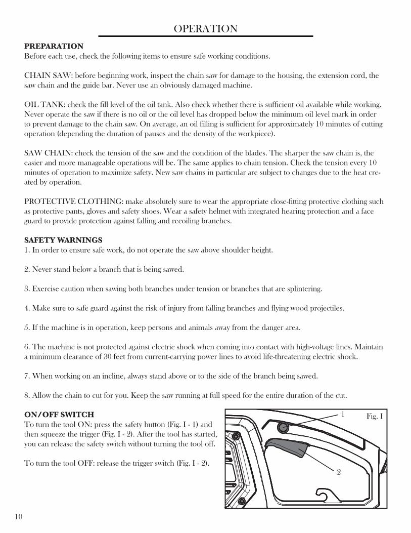
ON/OFF SWITCHTo turn the tool ON: press the safety button (Fig. I - 1) and then squeeze the trigger (Fig. I - 2). After the tool has started, you can release the safety switch without turning the tool off.
To turn the tool OFF: release the trigger switch (Fig. I - 2).
Fig. I1
2

11
OPERATION
SAWING TECHNIQUESSaw off the lower branches on the tree first. By doing so, it is easier for the cut branches to fall to the ground.
At the end of the cut, the weight of the saw suddenly increases for the user since it is no longer being supported by a branch. There is a risk of losing control of the saw, so make sure to stay alert during the entire sawing operation.
Only pull the saw out of a cut while the saw is running. By doing so, you prevent the chain from jamming in the wood.
Do not saw with the tip of the guide bar. Do not saw into the branch formations (where the tree branches out-wards). This will impede the tree’s ability to heal.
For sawing off smaller branches, place the stop face of the saw on the branch. This prevents unwanted movements of the saw at the beginning of the cut. While applying light pressure, guide the saw through the branch from top to bottom.
For sawing off larger branches, first make a relief cut. Saw through 1/3 of the branch diameter from the bottom to top using the top side of the guide bar. Then saw from top to bottom for the other 2/3 using the bottom side of the guide bar. Saw off longer branches in sections in order to maintain control over the location of impact.
PREVENTING KICKBACKThe term kickback refers to when the saw suddenly jumps up and back. This is usually caused by the workpiece coming into contact with the guide bar tip or the clamping of the saw chain.
A kickback generates an abrupt powerful force. The saw usually reacts in an uncontrolled manner, creating the possibility of injury to the user.
The danger of a kickback is greatest when attempting to cut near or with the guide bar tip. Always apply the saw as flatly as possible in order avoid a loss of control during operation.
WARNING: Do not cut down trees in high wind conditions. This can result in injury and should only be per-formed by a trained professional.
12
MAINTENANCECLEANINGRegularly clean the tensioning mechanisms by blowing compressed air onto it or by cleaning it with a brush. Do not use any tools for the cleaning.
Keep the oil away from the handle in order to ensure a secure hold.
Clean the machine as necessary with a damp cloth and a mild cleanser, if appropriate.
If the chain saw is not used for an extended period of time, remove the chain oil from the tank. Briefly place the chain and the guide bar in an oil bath and then wrap in oil paper to dry.
Always replace the protective cover for transport or storage of the chain saw. Secure the tool during transport to avoid damage or injuries. Unplug the power supply before cleaning. Never immerse the machine in water or other liquids. Store the chain saw in a safe and dry area away from children.
REPLACING THE SAW CHAIN AND GUIDE BARThe guide bar must be replaced if the groove of the guide is worn out or the spur wheel in the guide bar is dam-aged or worn out.
CHECKING THE AUTOMATIC CHAIN LUBRICATIONRegularly check the functionality of the automatic chain lubrication in order to prevent overheating and the subse-quent damage to the guide bar and saw chain associated with it. For this purpose, align the guide bar tip against a smooth surface (board, cut-in of a tree) and allow the chain saw to run. If an increasing amount of oil appears, the automatic chain lubrication functions properly.

13
TROUBLESHOOTING GUIDE
PROBLEM CAUSE SOLUTION
No power supply Check the power supply.
Defective outletTry a different source of power. Change as
necessary.
Damaged Extension cable Check cable and replace if necessary.
Safety button not pushed Push the safety button before pulling the trigger.
Chain too tight Adjust the chain tension.
Lubrication needed Check the oil levels and add oil as necessary.
Chain tension set incorrectly Adjust chain tension.
Chain tension set incorrectly Adjust chain tension.
Chain needs to be sharpened. Either sharpen or replace the chain.
Chain needs replacement. Replace the chain.
Chain installed backwards.Install the chain with the blades facing the
correct direction.Unit runs but does not cut.
Poor Cut Quality
Loose Chain
Overheating Chain/Bar
Saw does not operate properly

14
EXPLODED VIEW AND PARTS LIST
No. Part Number Part Description Qty
1 4017-001 Oil Tank Cap Assembly 11-1 4017-002 Cap Cover 11-2 4017-003 Oil Tank Cap 11-3 4017-004 Seal Ring 11-4 4017-005 Hanger 12 4017-006 The Oil Tank Opening Sealing Ring 13 4017-007 Oil Tank Assembly 1
3-1 4017-008 Valve 13-2 4017-009 Oil Tank 13-3 4017-010 Oil Box Joint Core Plug 13-4 4017-011 Sponge 13-5 4017-012 Oil Tank Delivery Connection 13-6 4017-013 Oil Tank Joint Rubber Sleeve 13-7 4017-014 Transparent Oil Hosing 14 4017-015 Power Line 15 4017-016 Cable Sheath 16 4017-017 Power Cable Screws 27 4017-018 Cable Clamp 18 4017-019 Connector 29 4017-020 Copper Strip 1
10 4017-021 Connecting Wire 111 4017-022 Connecting Wire 112 4017-023 Switch Spring 113 4017-024 Switch Button 114 4017-025 Anti Lock Button Spring 1
15 4017-026 Lock Button 1
16 4017-027 Plug Screw 1
17 4017-028 Microswitch 1
18 4017-029 Connecting Wire 1
19 4017-030 Hexagon Nut With Flange 1
20 4017-031 Motor Gear 1
21 4017-032 Motor Gear Bushing 1
22 4017-033 Motor Plate Screws 11
23 4017-034 Left Housing 1
24 4017-035 Rotor Subassembly 1
24-1 4017-036 Bearing 1
24-2 4017-037 Rotor 1
24-3 4017-038 Bearing 1
25 4017-039 Washer 1
26 4017-040 Stator Subassembly 1
26-1 4017-041 Stator Screw 2
26-2 4017-042 Spring Washer 2
26-3 4017-043 Flat Gasket 2
26-4 4017-044 Front Stator Housing 1
26-5 4017-045 Stator 1
26-6 4017-046 Motor Back 1
26-7 4017-047 Brush Mount 2
26-8 4017-048 Washer 2
No. Part Number Part Description Qty
26-9 4017-048 Hexagon Nut 227 4017-049 Brush 228 4017-050 Brush Cover 229 4017-051 Brush Cover Screws 430 4017-052 Motor Housing 131 4017-053 Brake Handle Screw 232 4017-054 Brake Washer 133 4017-055 Brake Handle 134 4017-056 Oil Pump Subassembly 1
34-1 4017-057 Worm Gear End 134-2 4017-058 Worm Gear 134-3 4017-059 Oil Pump 134-4 4017-060 Oil Pump Screws 135 4017-061 Transparent Oil Hosing 136 4017-062 Oil Nozzle 137 4017-063 Oring 238 4017-064 Output Shaft Subassembly 1
38-1 4017-065 Hex Lock Nut 138-2 4017-066 608Z Bearing 138-3 4017-067 Output Shaft Gear 138-4 4017-068 Output Shaft 138-5 4017-069 6900 Bearing 139 4017-070 Dust Shield 140 4017-071 Right Housing Sub Assembly 1
40-1 4017-072 Right Housing Plug 1
40-2 4017-073 Bumper Screws 2
40-3 4017-074 Clamp 1
40-4 4017-075 M8 Stud 1
40-5 4017-076 Right Housing 1
40-6 4017-077 Blade Adjustment Assembly 1
40-7 4017-078 Blade Adjustment Wheel 1
40-8 4017-079 Bumper 1
40-9 4017-080 Countersunk Bumper Screws 2
40-10 4017-081 Oil-Out Seal Ring 1
41 4017-082 Tensioning Spring 1
42 4017-083 Sprocket 1
43 4017-084 Chain Gear Baffle 1
44 4017-085 Clip 1
45 4017-086 Main Housing Screws 11
46 4017-087 Recessed Housing Screws 1
47 4017-088 Chain 1
48 4017-089 Bar 1
49 4017-090 Blade Adjustment Cover Assembly 1
49-1 4017-091 Knob 1
49-2 4017-092 Spindle 1
49-3 4017-093 Adjustment Cover 1
49-4 4017-094 End Cap Seal Ring 1
50 4017-095 Blade Cover 1

15
EXPLODED VIEW AND PARTS LIST

16
WEN Products is committed to building tools that are dependable for years. Our warranties are consistent with this commitment and our dedication to quality.
LIMITED WARRANTY OF WEN CONSUMER POWER TOOLS PRODUCTS FOR HOME USE
GREAT LAKES TECHNOLOGIES, LLC (“Seller”) warrants to the original purchaser only, that all WEN con-sumer power tools will be free from defects in material or workmanship for a period of two (2) years from date of purchase. Ninety days for all WEN products, if the tool is used for professional use.
SELLER’S SOLE OBLIGATION AND YOUR EXCLUSIVE REMEDY under this Limited Warranty and, to the extent permitted by law, any warranty or condition implied by law, shall be the repair or replacement of parts, without charge, which are defective in material or workmanship and which have not been misused, carelessly handled, or misrepaired by persons other than Seller or Authorized Service Center. To make a claim under this Limited Warranty, you must make sure to keep a copy of your proof of purchase that clearly defines the Date of Purchase (month and year) and the Place of Purchase. Place of purchase must be a direct vendor of Great Lakes Technologies, LLC. Third party vendors such as garage sales, pawn shops, resale shops, or any other secondhand merchant void the warranty included with this product. Contact [email protected] or 1-800-232-1195 to make arrangements for repairs and transportation.
When returning a product for warranty service, the shipping charges must be prepaid by the purchaser. The prod-uct must be shipped in its original container (or an equivalent), properly packed to withstand the hazards of ship-ment. The product must be fully insured with a copy of the warranty card and/or the proof of purchase enclosed. There must also be a description of the problem in order to help our repairs department diagnose and fix the issue. Repairs will be made and the product will be returned and shipped back to the purchaser at no charge.
THIS LIMITED WARRANTY DOES NOT APPLY TO ACCESSORY ITEMS THAT WEAR OUT FROM REGULAR USAGE OVER TIME INCLUDING BELTS, BRUSHES, BLADES, ETC. ANY IMPLIED WARRANTIES SHALL BE LIMITED IN DURATION TO TWO (2) YEARS FROM DATE OF PURCHASE. SOME STATES IN THE U.S., SOME CANADIAN PROVINCES DO NOT AL-LOW LIMITATIONS ON HOW LONG AN IMPLIED WARRANTY LASTS, SO THE ABOVE LIMITA-TION MAY NOT APPLY TO YOU.
IN NO EVENT SHALL SELLER BE LIABLE FOR ANY INCIDENTAL OR CONSEQUENTIAL DAM-AGES (INCLUDING BUT NOT LIMITED TO LIABILITY FOR LOSS OF PROFITS) ARISING FROM THE SALE OR USE OF THIS PRODUCT. SOME STATES IN THE U.S. AND SOME CANADIAN PROVINCES DO NOT ALLOW THE EXCLUSION OR LIMITATION OF INCIDENTAL OR CON-SEQUENTIAL DAMAGES, SO THE ABOVE LIMITATION OR EXCLUSION MAY NOT APPLY TO YOU.
THIS LIMITED WARRANTY GIVES YOU SPECIFIC LEGAL RIGHTS, AND YOU MAY ALSO HAVE OTHER RIGHTS WHICH VARY FROM STATE TO STATE IN THE U.S., PROVINCE TO PROVINCE IN CANADA AND FROM COUNTRY TO COUNTRY.
THIS LIMITED WARRANTY APPLIES ONLY TO PORTABLE ELECTRIC TOOLS, BENCH POW-ER TOOLS, OUTDOOR POWER EQUIPMENT AND PNEUMATIC TOOLS SOLD WITHIN THE UNITED STATES OF AMERICA, CANADA AND THE COMMONWEALTH OF PUERTO RICO. FOR WARRANTY COVERAGE WITHIN OTHER COUNTRIES, CONTACT THE WEN CUSTOMER SUP-PORT LINE.
LIMITED TWO YEARS WARRANTY