Embed Size (px)
Citation preview

Ste
el S
tructu
re C
ongre
ss,
Dubai, 1
6-1
8 N
ov.
2015
Dr Mohamed Elchalakani
Dubai Men’s College
UAE
Steel Structures Congress
16-18 November 2015
“CFRP Strengthening and Rehabilitation of
Corroded Steel Pipelines Under Combined
Bending and Bearing”

Ste
el S
tructu
re C
ongre
ss,
Dubai, 1
6-1
8 N
ov.
2015
Introduction
CFRP repair and strengthening of steel structures.
Types of Corrosion.
Traditional Methods of Repairs
Advantageous of using CFRP
Laboratory Testing
Cutting CFRP Sheets
Cleaning
Mixing Part A+B
Application to pipe surface
Test Results
Conclusions
Acknowledgment
Video ??
Introduction Testing Results Conclusions Acknowledgments

Ste
el S
tructu
re C
ongre
ss,
Dubai, 1
6-1
8 N
ov.
2015
Why Do We Need Repair and/or Strengthening
3
We need to strengthen or rehabilitate steel structures
because of:
1. Natural disasters (such as EQ.) or man-made
disasters such as road crashes
2. Environmental effects such as Corrosion
3. Increase in traffic demands or upgrades of existing
buildings.
Elchalakani, M. and Bambach M. (2007), Plastic Mechanism Analysis of CHS Stub Columns Strengthened
using CFRP, Journal of Structural Engineering, Melbourne University Press., Vol 7, 1-57.
Introduction Tests Results Design Acknowledgments

Ste
el S
tructu
re C
ongre
ss,
Dubai, 1
6-1
8 N
ov.
2015
4
Elchalakani, M. (2004), Design of Raw Mill Stack, New Preheater, New Raw Mill, Connell Wagner, Blue Circle
Cement, Waurn Ponds, Geelong, Victoria, Australia
Traditional Strengthening of Steel
Buildings, The Blue Circle
Southern Cement-Geelong,
Australia,
$100M Project
Introduction Tests Results Design Acknowledgments

Traditional Steel buildings Strengthening
Columns Strengthening
5
Ball Mill
Building
Welding Steel T-
stubs at mid-height
to increase the
Critical buckling
load

Traditional Strengthening Steel buildings
Floor and Walls Alterations - Beams and Braces
6
Adding New Steel Beams at new
cut-outs in the floor
Adding New Steel CHS Braces
at new cut-outs in the Side Walls
Adding New Steel CHS Braces
at new cut-outs in the Side Walls
Adding New Steel Beams at new
cut-outs in the floor

CFRP Strengthening of Steel Bridges
Modern Repair Work for Steel Structures
7

Rehabilitation of RHS using CFRP
Top, bottom and Web Surfaces-Rehabilitation
8
Original Section 5.0mm
thick. CFRP plates
location depends on the
available access.
Three levels of corrosion
at three different
locations:
a) 20% on Top, bottom
and web Plates
b) 40% on Top, bottom
and web Plates
c) 60% on Top, bottom
and web Plates
1.0 mm
1.0 mm
1.0 mm
1.0 mm
1.0 mm
20%40%
60%
5.0 mm

Test Results SME V-Wrap CFRP Strengthening of Box Girders
9
0
5
10
15
20
25
30
35
40
45
0 10 20 30 40 50 60 70 80
Load
(kN
)
Deflection (mm)
ST1-One Wrap
STT1-Two Wraps
S1-Bare
Plastic Compact Semi-compact Slender
1 Wrap 67.6 30.2 4.4 85.7
2 Wraps 98.6 34.0 13.3 185.7
0
20
40
60
80
100
120
140
160
180
200
% In
cre
ase
in
Str
en
gth
Deflection (mm)
Lo
ad
(kN
)
Elchalakani, M. and Fernando D. (2014), Repair and strengthening steel RHS beams strengthened with CFRP under 3-point bending,
Journal of Thin-Walled Structures, Elsevier, UK, Vol. 57, No 1, 58-71.

Strengthening Series-Failure Modes
Only the mid-span kink was observed
10
The failure modes observed
includes;
a) a ductile in-plane symmetric
collapse mode under large
bending deformation with the
top flange forming a deep
kink at mid-span associated
with web crippling) was
observed ;
b) The mixed mode where a
LTB mode formed together
with a deep mid-flange kink
and web crippling was not
observed
c) Pure LTB mode as Le/ry is
small was not observed

Rehabilitation Series-Failure Modes
Only the kink and mixed mode were observed
11
The failure modes observed
includes:
a) a ductile in-plane symmetric
collapse mode under large
bending deformation with the
top flange forming a deep kink
at mid-span associated with
web crippling); was observed
b) The mixed mode where a LTB
mode formed together with a
deep mid-flange kink and web
crippling for L=900 was
observed
c) Pure LTB mode as Le/ry is
small was not observed
Elchalakani, M. and Fernando D. (2014), Repair and strengthening steel RHS beams strengthened with CFRP under 3-point bending,
Journal of Thin-Walled Structures, Elsevier, UK, Vol. 57, No 1, 58-71.

CFRP Strengthening of I-beam Failure Modes
12
The failure modes observed
includes;
(a) a ductile in-plane
symmetric collapse mode
under large bending
deformation with the top
flange forming a deep kink
at mid-span associated with
web crippling (S1, S2, S3,
S6, SB1, SB2, SB3, STB1,
STB2, STB3 and STBW6);
(b) a mixed mode where a
LTB mode formed together
with a mild mid-flange kink
and web crippling (S5,
STBW5). Unfortunately,
(c) a pure LTB out-of-plane
lateral torsion buckling (
(S4, SB4, STB4),
Elchalakani, M. and Fernando D. (2012), Plastic Mechanism Analysis of unstiffened steel I-section beams strengthened with CFRP
under 3-point bending, Journal of Thin-Walled Structures, Elsevier, UK, Vol. 57, No 1, 58-71.

Corrosion Problem of Pipelines

Over 1.7 million km of Steel Pipelines, and Petroleum product
pipeline Worldwide

Corrosion has a huge economic and environmental impact on virtually all facets of the world’s infrastructure, from highways, bridges, and buildings to oil and gas, chemical processing, and water and wastewater systems. In addition to causing severe damage and threats to public safety, corrosion disrupts operations and requires extensive repair and replacement of failed assets. The annual cost of corrosion worldwide is estimated to exceed $1.8 trillion, which translates to 3 to 4% of the Gross Domestic Product (GDP) of industrialized countries. In the US, the annual cost of corrosion is estimated as $276B. The annual cost of corrosion to the Australian economy is estimated to be between $36B and $60B, whereas for the New Zealand economy the cost lies between $5.5B and $9.2B. Yet, governments and industries pay little attention to corrosion except in high-risk areas like aviation and maritime industries.
Economy loss due to corrosion

Result of interaction of the outer environment.
WATER
OXYGEN
(Exothermic reaction)
Formation of rust:
IRON OXIDE
The reaction between iron and oxygen in the presence of moisture or water.
Strong acid and oxidizing agents.
Corrosion

Types of corrosion
Local
corrosion is
the subject
of this paper

Uniform corrosion

External Patches
Traditional methods of repair
Welded sleeves
Bolted sleeves

24% cheaper than welded steel sleeve repairs
73% cheaper than replacing the damaged
section of the steel pipe
Short amount of time.
Undisrupted fluid transmission .
No Explosion potential.
Advantages of using CFRP Repair

Specimen Preparation

Carbon Fiber & Pipe Application
Carbon Fiber Sheet
V-Wrap™ C200

Uses Of Carbon Fiber
Aircraft…
Cars…
Bicycle and Motorcycle…
Buildings…
Steel Beams…
Steel Pipes…

Specimens Lc/D<3.0
24
Corrosion New ID thk tc Lc Lcfrp q CFRP Span Manufacturer Transvere Sheet Overlap Long Sheet Overlap
Level 21-Apr-14 mm mm mm mm Deg. mm
T5L0C0-01 5 0 0 0 0 0 900 SME V-Wrap C200 0 0 0 0
T5L0C0-02 5 0 0 0 0 0 900 SME V-Wrap C200 0 0 0 0
T5L0C0-03 5 0 0 0 0 0 600 SME V-Wrap C200 0 0 0 0
Corrosion Specimens ID thk tc Lc Lcfrp q CFRP Span Manufacturer Transverse Sheet Overlap Long Sheet Overlap
T4L1C0-0 4 1 100 0 360 0 900 SME V-Wrap C200 0 0 0 0
T4L1C2-1T1L 4 1 100 300 360 1L1T 900 SME V-Wrap C200 450 x 300 150 450 x 300 150
T4L1C2-2T2L 4 1 100 300 360 2L2T 900 SME V-Wrap C200 750 x 300 150 600 x 300 0
T4L2C0-0 4 1 200 0 360 0 900 SME V-Wrap C200 0 0 0 0
T4L2C4-1T1L 4 1 200 400 360 1L1T 900 SME V-Wrap C200 450 x 400 150 450 x 400 150
T4L2C4-2T2L 4 1 200 400 360 2L2T 900 SME V-Wrap C200 750 x 400 150 600 x 400 0
T4L3C0-0 4 1 300 0 360 0 900 0 0 0 0 0
Corrosion Specimens ID thk tc Lc Lcfrp q CFRP Span Manufacturer Transverse Sheet Overlap Long Sheet Overlap
T3L1C0-0 3 2 100 0 360 0 900 SME V-Wrap C200 0 0 0 0
T3L1C2-1T1L 3 2 100 300 360 1L1T 900 SME V-Wrap C200 450 x 300 150 450 x 300 150
T3L1C2-1T1L-SIKA 3 2 100 300 360 1L1T 900 SIKA 300C Wrap 450 x 300 150 450 x 300 150
T3L2C0-0 3 2 200 0 360 0 900 SME V-Wrap C200 0 0 0 0
T3L2C4-1T1L 3 2 200 400 360 1L1T 900 SME V-Wrap C200 450 x 400 150 450 x 400 150
T3L2C4-1T1L-SIKA 3 2 200 400 360 1L1T 900 SIKA 300C Wrap 450 x 400 150 450 x 400 150
T3L3C0-0 3 2 300 0 360 0 900 0 0 0 0 0
Corrosion Specimens ID thk tc Lc Lcfrp q CFRP Span Manufacturer Transverse Sheet Overlap Long Sheet Overlap
T2L1C0-0 2 3 100 0 360 0 900 SME V-Wrap C200 0 0 0 0
T2L1C2-1T1L 2 3 100 300 360 1L1T 900 SME V-Wrap C200 450 x 300 150 450 x 300 150
T2L1C2-1T1L-SIKA 2 3 100 300 360 1L1T 900 SIKA 300C Wrap 450 x 300 150 450 x 300 150
T2L2C0-0 2 3 200 0 360 0 900 SME V-Wrap C200 0 0 0 0
T2L2C4-1T1L 2 3 200 400 360 1L1T 900 SME V-Wrap C200 450 x 400 150 450 x 400 150
T24L2C4-1T1L-SIKA 2 3 200 400 360 1T1L 900 SIKA 300C Wrap 450 x 400 150 450 x 400 150
T2L3C0-0 2 3 300 0 360 0 900 SIKA 300C Wrap 0 0 0 0
Corrosion Specimens ID thk tc Lc Lcfrp q CFRP Span Manufacturer Transverse Sheet Overlap Long Sheet Overlap
T1L1C0-0 1 4 100 0 360 0 900 SME V-Wrap C200 0 0 0 0
T1L1C2-1T1L 1 4 100 300 360 1L1T 900 SME V-Wrap C200 450 x 300 150 450 x 300 150
T1L1C2-2T2L 1 4 100 300 360 2L2T 900 SME V-Wrap C200 750 x 300 150 600 x 300 0
T1L2C0-0 1 4 200 0 360 0 900 SME V-Wrap C200 0 0 0 0
T1L2C4-1T1L 1 4 200 400 360 1L1T 900 SME V-Wrap C200 450 x 400 150 450 x 400 150
T1L2C4-2T2L 1 4 200 400 360 2L2T 900 SME V-Wrap C200 750 x 400 150 600 x 400 0
T1L3C0-0 1 4 300 0 360 0 900 0 0 0 0 0
0%
20%
40%
60%
80%
Lcfrp
Lc
span

Specimens Lc/D=8.0
25
Corrosion New ID thk tc Lc Lcfrp q CFRP Span Manufacturer Transvere Sheet Overlap Long Sheet Overlap Application
21-Apr-14 mm mm mm mm Deg. mm
ST4L8C8-0 4 1 800 0 360 0 900 SME V-Wrap C200 0 0 0 0 0
ST4L8C8-2T2L 4 1 800 800 360 2L2T 900 SME V-Wrap C200
1 x 750 x 600 +
1 x 350 x 750 150 600 x 800 0 2L2T
ST4L8C8-4T4L 4 1 800 800 360 4L4T 900 SME V-Wrap C200
2 x 750 x 600 +
2 x 350 x 750 150 2 x 600 x 800 0 2L2T2L2T
Corrosion Specimens ID thk tc Lc Lcfrp q CFRP Span Manufacturer Transverse Sheet Overlap Long Sheet Overlap
ST3L8C8-0 3 2 800 0 360 0 900 SME V-Wrap C200 0 0 0 0 0
ST3L8C8-2T2L 3 2 800 800 360 2L2T 900 SME V-Wrap C200
1 x 750 x 600 +
1 x 350 x 750 150 600 x 800 0 2L2T
ST3L8C8-4T4L 3 2 800 800 360 4L4T 900 SME V-Wrap C200
2 x 750 x 600 +
2 x 350 x 750 150 2 x 600 x 800 0 2L2T2L2T
Corrosion Specimens ID thk tc Lc Lcfrp q CFRP Span Manufacturer Transverse Sheet Overlap Long Sheet Overlap Overlap
ST2L8C8-0 2 3 800 0 360 0 900 SME V-Wrap C200 0 0 0 0 0
ST2L8C8-2T2L 2 3 800 800 360 2L2T 900 SME V-Wrap C200
1 x 750 x 600 +
1 x 350 x 750 150 600 x 800 0 2L2T
ST2L8C8-4T4L 2 3 800 800 360 4L4T 900 SME V-Wrap C200
2 x 750 x 600 +
2 x 350 x 750 150 2 x 600 x 800 0 2L2T2L2T
Corrosion Specimens ID thk tc Lc Lcfrp q CFRP Span Manufacturer Transverse Sheet Overlap Long Sheet Overlap Overlap
ST1L8C8-0 1 4 800 0 360 0 900 SME V-Wrap C200 0 0 0 0 0
ST1L8C8-2T2L 1 4 800 800 360 2L2T 900 SME V-Wrap C200
1 x 750 x 600 +
1 x 350 x 750 150 600 x 800 0 2L2T
ST1L8C8-4T4L 1 4 800 800 360 4L4T 900 SME V-Wrap C200
2 x 750 x 600 +
2 x 350 x 750 150 2 x 600 x 800 0 2L2T2L2T
20%
40%
60%
80%
Lcfrp
Lc
span

The total number of specimens is 43

The total number of specimens is 43
250 kN Max Load
Loading Ram
Load Cell
Test specimen
Span (L)
Saddle Supports
102 mm Diameter
1000 mm
D0
A
A
Loading Rod
40 mm diameter
Lc
Lcfrp
CFRP Wraps with length Lcfrp
cover the corroded section of
length Lc along the pipe
D
CFRP
t f
t s

One-Column Format
Slide 28
Mechanical Properties of CFRP
Manufacturer Sika Plates
CarboDur S
Sika Sikadur
330 Sheets
Structural Tech
C180 V-Wrap E
-Mo
du
lue
s
Mean Value 165,000 N/mm2 230,000 N/mm2 227,000 N/mm2
Min Value > 160,000
N/mm2
> 230,000
N/mm2
> 227,000
N/mm2
5% Fractile Value 162,000 N/mm2 230,000 N/mm2 227,000 N/mm2
95% Fractile Value 180,000 N/mm2 230,000 N/mm2 227,000 N/mm2
Te
ns
ile
Str
en
gth
Mean Value 3,100 N/mm2 3,500 N/mm2 4,000 N/mm2
Min Value > 2,800 N/mm2 > 3,500 N/mm2 4,000 N/mm2
5% Fractile Value 3,000 N/mm2 3,500 N/mm2 4,000 N/mm2
95% Fractile Value 3,600 N/mm2 3,500 N/mm2 4,000 N/mm2
Stain at Break* (Min Value) > 1.70% > 1.5% > 1.70%
Thickness (mm) 1.2 0.13 0.28

CFRP Plates and Mild Steel Tensile Properties
ICIMART14,
AUS, 4-6 March
2014
29
2800
Stress ( MPa )
Strain (%)
1.7 %
Ef=160 Gpa
CFRP CarboDur
S1012
Steel grade S275
275
20 %
Es=200 Gpa

Prepare Carbon Fiber
Cutting Measurement

Pipe Application…
Cleaning
• Sanding
• Grinding
Adhesive Mixing
• Part A
• Part B
Carbon Saturated
• Saturated
• Transverse& Longitudinal
1 2 3

Cleaning

Cleaning
Sanding

Cleaning
Grinding

Adhesive Mixing
Mixing Part A

Adhesive Mixing
Mixing Part B
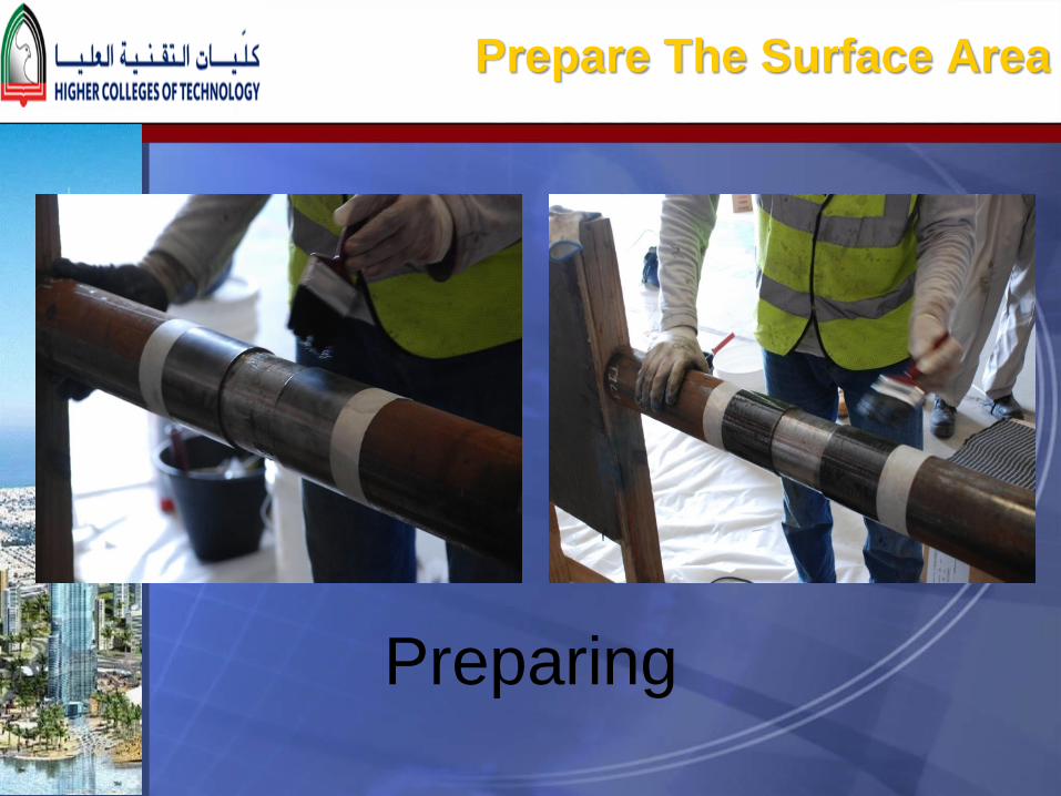
Prepare The Surface Area
Preparing
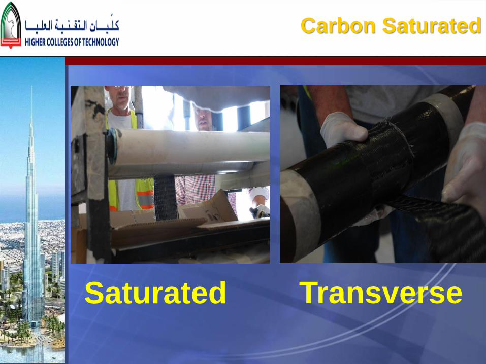
Carbon Saturated
Saturated Transverse


Carbon Saturated
Longitudinal Saturated


Why Transverse & Longitude Direction?

2. Laboratory Testing

Test Set up
44

Failure Modes
CFRP System
Fibre Fracture
Local Buckling
Intermediate Plate Debonding
Steel Pipe
Steel Fracture
Local Buckling
45

3. Test Results

Specimens after Testing

Gain in Strength due to CFRP
0
50
100
150
200
250
300
0% 20% 40% 60% 80% 100%
% In
cre
ase
in L
oad
Cap
acit
y
% All around 360 Deg Thickness Corrosin
20% Corrosion-Rehabilitation
40% Corrosion-Rehabilitation
60% Corrosion-Rehabilitation
80% Corrosion-Rehabilitation

Structural Technology wrapping System Provided
higher strength
0
10
20
30
40
50
60
70
80
90
100
0% 20% 40% 60% 80% 100%
% In
cre
ase
in L
oad
Cap
acit
y
% All around 360 Deg Thickness Corrosin
40% Corrosion-Rehabilitation
60% Corrosion-Rehabilitation
SIKA (70%, 86%)
Structural(60%, 93%)
SIKA(31%, 49%)
Structural(35%, 62%)

Effect of the corrosion length (Lc) on the normalised strength (%Pu/Pu,control)
0
20
40
60
80
100
120
0 50 100 150 200 250 300
% (P
u/Pu
,con
trol
)
Corrosion Length (Lc) mm
0% corrosion 20% Corrosion 40% corrosion
60% Corrosion 80% Corrosion

Load-deflection Curves
0
10
20
30
40
50
60
70
80
0 50 100 150 200 250
Lo
ad
(k
N)
Deflection (mm)
T4L2C0-0
T4L1C2-1T1L
T4L1C2-2T2L
T5L0C0-01
Bare steel No fracture
2T2L
1T1L
control
( a ) 20% corrosion (b) 40% corrosion
0
10
20
30
40
50
60
70
80
0 50 100 150 200 250
Lo
ad
(k
N)
Deflection (mm)
T3L1C0-0
T3L1C2-1T1L-SIKA
T3L1C2-1T1L
T5L0C0-01
Bare steel No fracture
1T1L - SIKA
1T1L -Structural
control - local buckling
20% Corrosion 40% Corrosion

Load-deflection Curves
( a ) 20% corrosion (b) 40% corrosion
60% Corrosion 80% Corrosion
0
10
20
30
40
50
60
70
80
0 50 100 150 200 250
Loa
d (
kN
)
Deflection (mm)
T2L1C2-1T1L-SIKA
T2L1C2-1T1L
T2L1C0-0
T5L0C0-01
local buckling
Bare steel fracture
1T1L - StructuralNo fibre rupture1T1L fibre
rupture - SIKA
controlLocal buckling
0
10
20
30
40
50
60
70
80
0 50 100 150 200 250
Lo
ad
(k
N)
Deflection (mm)
T1L1C0-0
T1L1C2-1T1L
T1L1C2-2T2L
T5L0C0-01
Bare steel fracture
2T2L
1T1L
Control

Design Method for Repair System Under Combined Bending and Bearing
0
0.2
0.4
0.6
0.8
1
1.2
0 0.2 0.4 0.6 0.8 1 1.2
Mu/
Mpc
Pu/Rbyc
CHS-Bare Steel Tests
CHS+CFRP Composite Repair Tests
Hou etal [40]-CHS Bearing Tests
Equation 10 - Lower bound for bare CHS
Equation 11 - Lower bound for CHS+CFRP
1.0u u
byc pc
P M
R M
for bare CHS where D0/ts = 1642 and Lc/D0 = 3.0 (10)
1.2u u
byc pc
P M
R M
for repaired CHS using CFRP where D0/ts = 1642 and Lc/D0 = 3.0 (11)

Conclusions
The results showed that the combined flexural and bearing strength of the
repaired steel pipelines can be significantly increased by adhesively bonding
CFRP.
The percent increase in strength was mostly affected by the corrosion level
where the maximum gain was 434% which was obtained for the most severe
80% corrosion in the wall thickness. The average increase in the load
carrying capacity was 97% and 169% for the rehabilitation and strengthening
series, respectively.
The stiffness and capacity of the un-corroded control specimen was fully
restored for the repaired specimens with 20% corrosion in the wall. However,
for higher levels of corrosion of 40% to 80% such stiffness and capacity were
not fully restored. Thus adding more CFRP sheets in the circumferential and
longitudinal directions may restore the un-corroded stiffness and capacity for
40% to 80% corrosion.
Design equations based on the bare and composite section properties were
derived to predict the strength of bare and repaired CHS using CFRP under
combined bending and bearing.

Ste
el S
tructu
re C
ongre
ss,
Dubai, 1
6-1
8 N
ov.
2015
Introduction Testing Results Design Acknowledgments
The author would like to thank Dr. Tarek Alkhrdaji and Mr Christian Hill
of “Structural Technologies” for providing the CFRP sheets and for the
kind support for our ongoing research.
The assistance and support of Sika staff in particular Mr Rob Bonnici
and Eng Imad is greatly appreciated.
Also, thanks are given to Eng. Yousef Al Sharhan and Mr Humaid
Saeed Al-Merri the head of Transport division at Dubai Municipality for
assisting the students in welding the specimens.
The author would like to thank Eng Ali Elian and Eng Hwa albastaki at
Dubai Municipality Central Laboratory for assisting the students in
testing the specimens
The author would like to thank the following students of Dubai Men’s
College for performing the experiments: Waleed Albloushi, Yahya
Almulla, Mohammed Abudulla, Mohamed Darwish, Ahmed Ahli, Fah
Saleh, Ali Mohamed, Ebrahim Mohammed, Salim Almarzogi, Mohamed
Salim, Syed Alhashmi.

Ste
el S
tructu
re C
ongre
ss,
Dubai, 1
6-1
8 N
ov.
2015
Introduction Testing Results Design Video