Embed Size (px)
Citation preview

1.5HP 220V VARIABLE SPEED IN GROUND POOL PUMP
SAVE THIS MANUAL: KEEP THIS MANUAL FOR SAFETY WARNINGS, PRECAUTIONS, ASSEMBLY, OPERATING, INSPECTION, MAINTENANCE AND CLEANING PROCEDURES. WRITE THE PRODUCT’S SERIAL NUMBER ON THE BACK OF THE MANUAL NEAR THE ASSEMBLY DIAGRAM (OR MONTH
AND YEAR OF PURCHASE IF PRODUCT HAS NO NUMBER).
OWNER’S MANUAL AND SAFETY INSTRUCTIONS
ITEM: 75021
FOR QUESTIONS PLEASE CALL OUR CUSTOMER SUPPORT: (909) 628 0880 MON-FRI 9AM TO 3PM PST
IMPORTANT SAFETY INFORMATION
GENERAL SAFETY WARNINGSRead all safety warnings and instructions. Failure to follow the warnings and instructions may result in electric shock, fire and/or serious injury. Save all warnings and instructions for future reference.
SAFETY
The warnings, precautions, and instructions discussed in this instruction manual cannot cover all possible conditions and situations that may occur. It must be understood by the operator that common sense and caution are factors which cannot be built into this product, but must be supplied by the operator. Read carefully and understand all ASSEMBLY AND OPERATION INSTRUCTIONS before operating. Failure to follow the safety rules and other basic safety precautions may result in serious personal injury.
1
Read and understand all instructions. Failure to follow all instructions may result in serious injuryor property damage.DO NOT allow persons to operate or assemble the product until they have read this manual andhave developed a thorough understanding of how it works.
DO NOT modify this product in any way. Unauthorized modification may impair the function and/orsafety and could affect the life of the product. There are specific applications for which the productwas designed.
Use the right tool for the job. DO NOT attempt to force small equipment to do the work of largerindustrial equipment. There are certain applications for which this equipment was designed. Thisproduct will be safer and do a better job at the capacity for which it was intended. DO NOT usethis equipment for a purpose for which it was not intended.
Keep children and bystanders away from the work area while operating the tool. DO NOT allowchildren to handle the product.
This pump is intended for use on permanently installed swimming pools and may also be used with hot tubs and spas if so marked. DO NOT use with storable pools. A permanently installed pool is constructed in or on the ground or in a building such that it cannot be readily disassembled for storage. A storable pool is constructed so that it is capable of being readily disassembled for storage and reassembled to its original integrity.
Though this product is designed for outdoor use, it is strongly advised to protect the electrical components from the weather. Select a well-drained area, one that will not flood when it rains. It requires free circulation of air for cooling. DO NOT install in a damp or non-ventilated location.Pool and spa components have a finite life. All components should be inspected frequently and replaced at least every five years, or if found to be damaged, broken, cracked, missing, or not securely attached.
Hazardous voltage can shock, burn, or cause death. To reduce the risk of electric shock, DO NOT use an extension cord to connect unit to electric supply. Provide a properly located outlet. It is required that licensed electricians do all electrical wiring. All electrical wiring MUST be in conformance with applicable local and national codes and regulations. Before working on pump or motor, disconnect motor wiring.

IMPORTANT SAFETY INFORMATION
2
To reduce the risk of electric shock replace damaged cord immediately. DO NOT bury cord. Locate cord to prevent abuse from lawn mowers, hedge trimmers and other equipment.
Risk of Electric Shock. Connect only to a branch circuit protected by a ground-fault circuit-interrupter (GFCI). Contact only to a electrician if you cannot verify that the receptacles is protected by a GFCI.
Failure to bond pump to pool structure will increase risk for electrocution and could result in injury or death. To reduce the risk of electric shock, see installation instructions and consult a professional electrician on how to bond pump. Also, contact a licensed electrician for information on local electrical codes for bonding requirements.
Use a solid copper conductor, size 8 or larger. Run a continuous wire from external bonding lug to reinforcing rod or mesh. Connect a No. 8 AWG (8.4 mm2) solid copper bonding wire to the pressure wire connector provided on the motor housing and to all metal parts of swimming pool, spa, or hot tub, and to all electrical equipment, metal piping (except gas piping), and conduit within 5 ft. (1.5m) of inside walls of swimming pool, spa, or hot tub. IMPORTANT - Reference NEC codes for all wiring standards including, but not limited to, grounding, bonding and other general wiring procedures. NOTE - The National Electrical Code (NEC) permits use of a cord with a maximum 3 ft. (1 m) length. If your pump is equipped with a cord complying with the NEC
DO NOT install within an outer enclosure or beneath the skirt of a hot tub or spa.
Suction Entrapment Hazard: Suction in suction outlets and/or suction outlet covers, which are damaged, broken, cracked, missing or unsecured cause severe injury and/or death due to the following entrapment hazards:Hair Entrapment- Hair can become entangled in suction outlet cover.Limb Entrapment- A limb inserted into an opening of a suction outlet sump or suction outlet cover that is damaged, broken, cracked, missing, or not securely attached can result in a mechanical bind or swelling of the limb.Body Suction Entrapment- A pressure applied to a large portion of the body or limbs can result in an entrapment.Evisceration/ Disembowelment- A negative pressure applied directly to the intestines through an unprotected suction outlet sump or suction outlet cover which is damaged, broken, cracked, missing, or unsecured can result in evisceration/disembowelment.Mechanical Entrapment- There is potential for jewelry, swimsuits, hair decorations, fingers, toes, or knuckles to be caught in an opening of a suction outlet cover resulting in mechanical entrapment.
To Reduce the risk of Entrapment Hazards: When outlets are small enough to be blocked by a person, a minimum of two functioning suction outlets per pump must be installed. Suction outlets in the same plane (i.e. floor or wall), must be installed a minimum of three feet (3’) [0.91 meter] apart, as measured from near point to near point.- Dual suction fittings shall be placed in such locations and distances to avoid “dual blockage” by a user.- Dual suction fittings shall not be located on seating areas or on the backrest for such seating areas.- The maximum system flow rate shall not exceed the values shown in the “Pipe Sizing Chart” found at this manual.- Never use pool or spa if any suction outlet component is damaged, broken, cracked, missing, or not securely attached.- Replace damaged, broken, cracked, missing, or not securely attached suction outlet components immediately.- Installation of a vacuum release or vent system, which relieves entrapping suction, is recommended.
Pump MUST be permanently connected to circuit. If other lights or appliances are also on the same circuit, be sure to add their amp loads before calculating wire and circuit breaker sizes. Use the load circuit breaker as the Master On-Off switch.
3
IMPORTANT SAFETY INFORMATION
Hazardous Pressure: Pool and spa water circulation systems operate under hazardous pressure during start-up, normal operation, and after pump shut-off. Stand clear of circulation system equipment during pump start-up. Failure to follow safety and operation instructions could result in violent separation of the pump housing and cover due to pressure in the system, which could cause property damage, severe personal injury, or death. Before servicing pool and spa water circulation system, all system and pump controls must be in off position and filter manual air relief valve must be in open position. Before starting system pump, all system valves must be set in a position to allow system water to return back to the pool. DO NOT change filter control valve position while system pump is running. Before starting system pump, fully open filter manual air relief valve. DO NOT close filter manual air relief valve until a steady stream of water (not air or air and water) is discharged. All suction and discharge valves MUST be OPEN when starting the circulation system. Failure to do so could result in severe personal injury and/or property damage.Separation Hazard: Failure to follow safety and operation instructions could result in violent separation of pump components. Strainer cover must be properly secured to pump housing with strainer cover lock ring. Before servicing pool and spa circulation system, all system and pump controls must be in off position and filter manual air relief valve must be in open position. DO NOT operate pool and spa circulation system if a system component is not assembled properly, damaged, or missing. DO NOT operate pool and spa circulation system unless filter air relief valve body is in locked position in filter upper body. All suction and discharge valves MUST be OPEN when starting the circulation system. Failure to do so could result in severe personal injury and/or property damage. NEVER operate or test the circulation system at more than 40 PSI.
Fire and Burn Hazard: Motors operate at high temperatures and if they are not properly isolated from any flammable structures or foreign debris they can cause fires, which may cause severe personal injury or death. It is also necessary to allow the motor to cool for at least 20 minutes prior to maintenance to minimize the risk for burns.This product should be installed and serviced only by a qualified professional.If pump is being pressure tested (40 PSI MAXIMUM), be sure pressure has been released, using the filter manual air relief valve, before removing strainer cover.
NEVER run pump dry. Running pump dry may damage seals, causing leakage, flooding, and voids warranty. Fill strainer housing with water before starting motor.Match supply voltage to motor nameplate voltage. Insure that the electrical supply available agrees with the motor’s voltage, phase, and cycle, and that the wire size is adequate for the (KW) rating and distance from the power source.
All suction and discharge valves MUST be OPEN, as well as filter air relief valve (if available) on filter, when starting the circulating pump system. Failure to do so could result in severe personal injury.
To avoid dangerous or fatal electrical shock hazard, turn OFF power to motor before draining pump. Failure to disconnect power may result in serious personal injury or death.
Install, ground, bond, and wire motor in accordance with local or national electrical code requirements.Permanently ground motor. Use green ground terminal provided under motor canopy or access place; use size and type wire required by code. Connect motor ground terminal to electrical service ground.Bond motor to pool structure. Bonding will connect all metal parts within and around the pool with a continuous wire. Bonding reduces the risk of a current passing between bonded metal objects, which could potentially cause electrical shock if grounded or shorted. Reference NEC codes for all wiring standards including, but not limited to, grounding, bonding and general wiring procedures.
Fittings restrict flow. For better efficiency, use the fewest possible fittings (but at least two suction outlets). Avoid fittings that could cause an air trap. Pool and spa fittings MUST conform to the International Association of Plumbing and Mechanical Officials (IAPMO) standards. Use a non-entrapping suction fitting in pool (multiple drains) or double suction (skimmer and main drain).
4
DIAGRAM AND SPECIFICATIONS
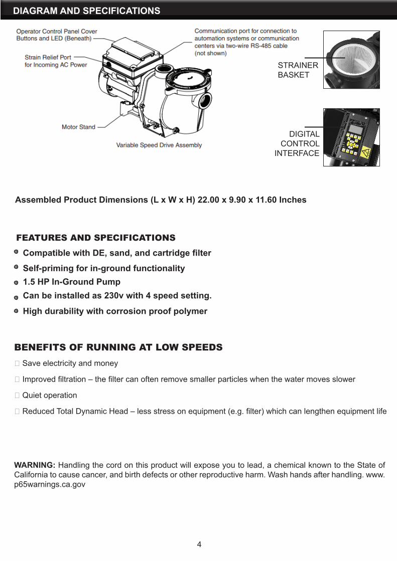
FEATURES AND SPECIFICATIONSCompatible with DE, sand, and cartridge filter
Assembled Product Dimensions (L x W x H) 22.00 x 9.90 x 11.60 Inches
Self-priming for in-ground functionality1.5 HP In-Ground PumpCan be installed as 230v with 4 speed setting.
High durability with corrosion proof polymer
WARNING: Handling the cord on this product will expose you to lead, a chemical known to the State of California to cause cancer, and birth defects or other reproductive harm. Wash hands after handling. www.p65warnings.ca.gov
BENEFITS OF RUNNING AT LOW SPEEDS Save electricity and money
Improved filtration – the filter can often remove smaller particles when the water moves slower
Quiet operation
Reduced Total Dynamic Head – less stress on equipment (e.g. filter) which can lengthen equipment life
STRAINER BASKET
DIGITAL CONTROL
INTERFACE

DIGITAL CONTROL INTERFACE
5
6
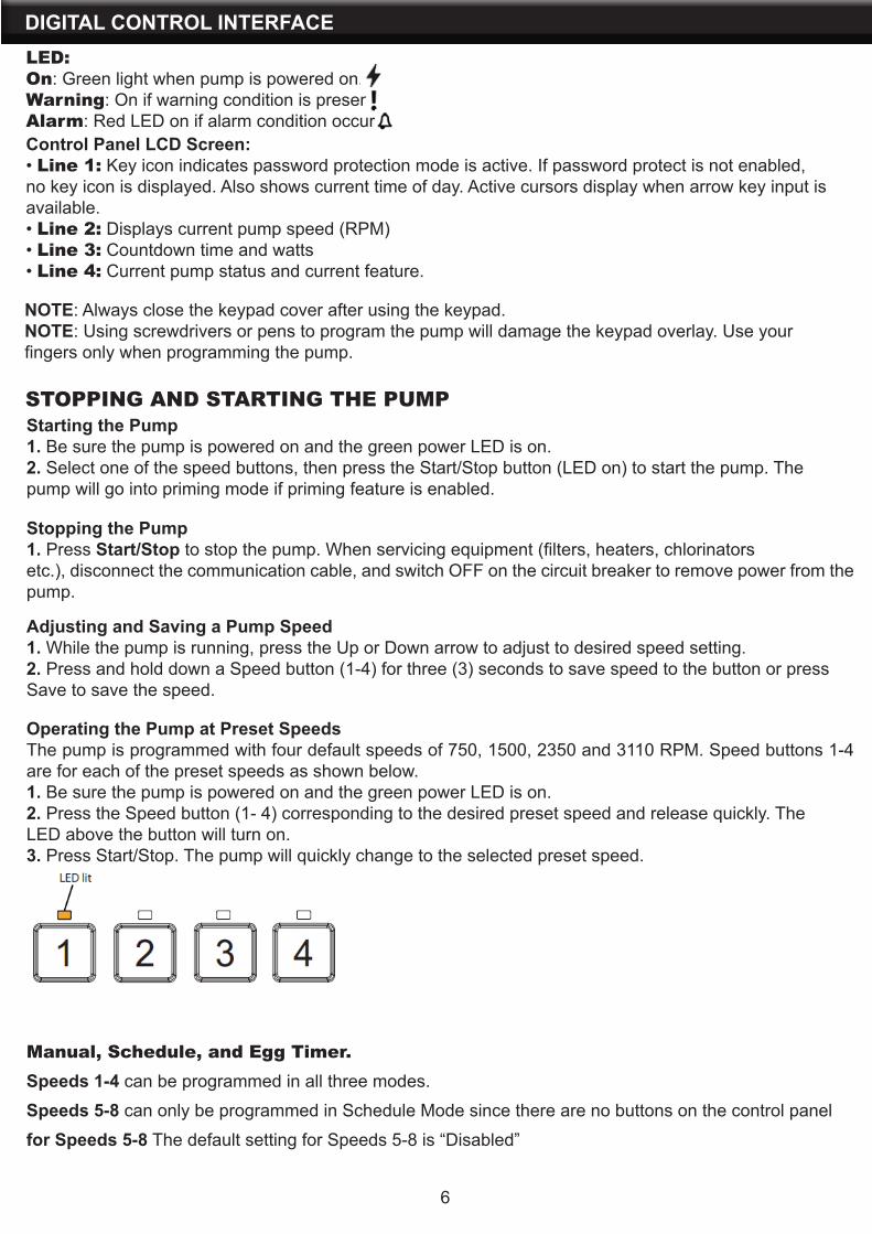
DIGITAL CONTROL INTERFACELED:On: Green light when pump is powered on.Warning: On if warning condition is present.Alarm: Red LED on if alarm condition occurs.Control Panel LCD Screen:• Line 1: Key icon indicates password protection mode is active. If password protect is not enabled, no key icon is displayed. Also shows current time of day. Active cursors display when arrow key input is available.• Line 2: Displays current pump speed (RPM)• Line 3: Countdown time and watts• Line 4: Current pump status and current feature.
NOTE: Always close the keypad cover after using the keypad. NOTE: Using screwdrivers or pens to program the pump will damage the keypad overlay. Use yourfingers only when programming the pump.
STOPPING AND STARTING THE PUMPStarting the Pump1. Be sure the pump is powered on and the green power LED is on.2. Select one of the speed buttons, then press the Start/Stop button (LED on) to start the pump. Thepump will go into priming mode if priming feature is enabled.
Stopping the Pump1. Press Start/Stop to stop the pump. When servicing equipment (filters, heaters, chlorinatorsetc.), disconnect the communication cable, and switch OFF on the circuit breaker to remove power from the pump.
Adjusting and Saving a Pump Speed1. While the pump is running, press the Up or Down arrow to adjust to desired speed setting.2. Press and hold down a Speed button (1-4) for three (3) seconds to save speed to the button or pressSave to save the speed.
Operating the Pump at Preset SpeedsThe pump is programmed with four default speeds of 750, 1500, 2350 and 3110 RPM. Speed buttons 1-4 are for each of the preset speeds as shown below.1. Be sure the pump is powered on and the green power LED is on.2. Press the Speed button (1- 4) corresponding to the desired preset speed and release quickly. TheLED above the button will turn on.3. Press Start/Stop. The pump will quickly change to the selected preset speed.
Manual, Schedule, and Egg Timer.Speeds 1-4 can be programmed in all three modes.
Speeds 5-8 can only be programmed in Schedule Mode since there are no buttons on the control panel
for Speeds 5-8 The default setting for Speeds 5-8 is “Disabled”
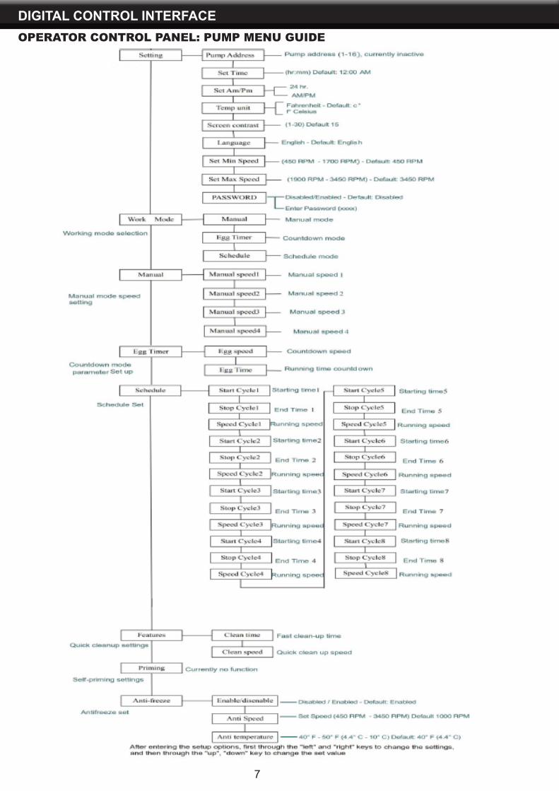
DIGITAL CONTROL INTERFACEOPERATOR CONTROL PANEL: PUMP MENU GUIDE
7

8
DIGITAL CONTROL INTERFACE
SET DATE AND TIMEThe time controls all scheduled times, functions, and programmed cycles and stores the correct time for upto 96 hours after power is turned off. Reset if the power is off longer than 96 hours.1. Check that the green power LED is on.2. Press Menu.3. Press Select to select “Settings”.4. Use the Up or Down arrows to scroll to “Date and Time” and press Select.5. Press Select again and use Up or Down arrows to set the date.6. Press Enter to save user input and return to “Date and Time.”7. Use the Up or Down arrows to scroll to “Time” and press Select.8. Use the Up or Down arrows to scroll to set the time. Note: To set AM/PM or a 24 hour clock see the nextsection “Set AM/PM or 24 Hour Clock.”9. Press Enter to save. To cancel any changes, press Escape to exit without saving.10. Press Escape to exit.
SET AM/PM OR 24 HOUR CLOCKTo change the time from a 12 hour clock (AM/PM) to a 24 hour clock:1. Press Menu.2. Press Select to select “Settings”.3. Use the Up or Down arrows to scroll to “Date and Time” and press Select.4. Use the Up or Down arrows to scroll to “AM/PM” and press Select.5. Use the Up or Down arrows to scroll to choose between 24 hr. and AM/PM.6. Press Enter to save. To cancel any changes, press Escape to exit without saving.7. Press Escape to exit.
SET MINIMUM SPEED (RPM)The minimum pump speed can be set from 450 RPM to 1700 RPM. The default setting is 450 RPM.1. Check that the green power LED is on.2. Press Menu.3. Press Select to select “Settings”.4. Use the Up or Down arrows to scroll to “Min/Max”.5. Use the Up or Down arrows to scroll to “Set Min Spd”.6. Press Select to change the setting. The cursor will appear in the first number column (ones).7. Press the Up or Down arrows to change the minimum speed setting from 450 to 1700 RPM.8. Press Enter to save. To cancel, press Escape to exit edit mode without saving.9. Press Escape to exit.
PUMP ADDRESSThis setting is reserved for connecting pump via the port to an automation system. No function at present.
SET SCREEN CONTRASTThe default setting for the LCD screen is 15. Screen contrast levels can be adjusted from 0 to 30 units forlow or high lighting conditions. Note: Changes to the contrast setting do not update instantaneously.Changes to this setting must be saved before the contrast level changes.1. Check that the green power LED is on.2. Press Menu.3. Press Select to select “Settings”.4. Use the Up or Down arrow to scroll to “Device” and press Select.5. Use the Up or Down arrow to scroll to “Contrast Level.”6. Press Select. Screen will show current contrast setting number. Use Up or Down to change number.7. Press Escape to save. To cancel any changes, press Escape to exit without saving.8. Press the Escape button to exit.

1. Check that the green power LED is on.2. Press Menu. Press Select to select “Settings”.3. Use the Up or Down arrow to scroll to “Device”.4. Press Select.5. Press Up or Down arrow to scroll to “Password”. The default setting is “Disabled”.6. Press Select.7. Press Up or Down arrow to change the setting to “Enabled”. Press Enter to save.8. Press the Down arrow. “Password Timeout” will be displayed. The factory default time is 1 minute. Thismeans the Variable Speed Pump will go into Password Protection mode 1 minute after the last controlpanel key is pressed.9. Press Select to change time setting from 1 minute to 6 hours and press Enter to save.10. Press the Down arrow and then press Select on “Enter Password” to change the setting.11. Press the Left or Right arrows to move cursor and press the Up or Down arrow to change thepassword number to desired setting.12. Press Enter to save. To cancel any changes, press Escape to exit without saving.
DIGITAL CONTROL INTERFACE
9
SET CONTROL PANEL LANGUAGETo access the language menu:1. Check that the green power LED is on.2. Press Menu and press Select to select “Settings”.3. Use the Up or Down arrows and scroll to “Device” and press Select.4. Use the Up or Down arrows to scroll to “Select Language and press Select.5. Use the Up or Down arrows to choose the desired language.6. Press Enter to select the control panel language. To cancel any changes, press Escape to exitwithout saving.7. Press Escape to exit.
SET TEMPERATURE UNITThe default setting is Fahrenheit (°F). The pump can be set to either Celsius (°C) or Fahrenheit (°F).1. Check that the green power LED is on.2. Press Menu.3. Press Select to select “Settings”.4. Use the Up or Down arrows to scroll to “Device” menu item. Press Select.5. Use Up or Down arrows to scroll to “Temperature Units” and press Select.6. Use Up or Down arrows to choose Celsius (°C) or Fahrenheit (°F).7. Press Enter to save. To cancel any changes, press Escape to exit without saving.8. Press Escape to exit.
SET CONTROL PANEL LANGUAGEPassword ProtectionThe default setting for password protection is disabled. When this feature is enabled, the pump display will prompt for the password before allowing access to the control panel and buttons. The entered password is any combination of four (4) digits.• The pump can always be stopped by pressing Start/ Stop, even when password protection is enabled.• Password protection cannot be turned back on with Start/Stop while running in manual mode.• Pressing Start/Stop when the pump is off will return it back to the Running Cycles Mode and run atthe next scheduled run time. If the present time is within the scheduled run time, the pump will run the scheduled speed.• All functions including programming are disabled in Password Protection Mode.• Screen will read “Enter Password” if any button other than the Start/Stop button is pressed• Key icon displayed in the upper left side of the screen when Password Protection is on.
SETTING PASSWORD

DIGITAL CONTROL INTERFACE
10
Entering Password1. Press any button (besides the speed button) to prompt the screen for a password.2. To enter password, use the “Speed” button to input the number 1-4 and then press the Enter button toconfirm.
PUMP OPERATING MODESThe Variable Speed Pump can be programmed in three different modes: Manual, Schedule, and Egg Timer.Speeds 1-4 can be programmed in all three modes. Speeds 5-8 can only be programmed in Schedulemode since there are no buttons on the control panel for Speeds 5-8. The default setting for Speeds 5-8 is“Disabled”.
MANUALAssigns a speed to one of the four Speed buttons on the control panel. This mode can only be used forspeeds 1-4. To operate in Manual mode, press one of the four speed buttons and then press the Start/Stopbutton. The pump will run the assigned speed for that speed button.
EGG TIMERMenu - Setting - Egg timer, egg timer speed is displayed, use the or arrow button to move the cursor, anduse the arrow button to change the number. The range of the speed is 450RPM-3450RPM. Press Enter tosave settings. Press Select, egg timer time is displayed, use the arrow button to set time. The time range is00:01-19:59.
SCHEDULEProgram speeds 1-8 start and stop at a specific time during a 24 hour period. Speeds programmed inSchedule mode will override any manually selected speed (Schedule program preset in factory, can bechanged manually).
SET SPEEDS IN MANUAL MODE (SPEEDS 1-4 ONLY)1. Press Menu.2. Use Up or Down arrows to scroll to “Manual”, then press Select.3. Use Up or Down arrows to find the speed (1-4) you wish to program, then press Select.4. Press Slect, access manual speed setting change, Use Left or Right arrow button to change thecursor highlight the number which will be changed. And use Up or Down arrow button to change thenumbers.5. Press Enter to save the new speed setting.
DIGITAL CONTROL INTERFACE
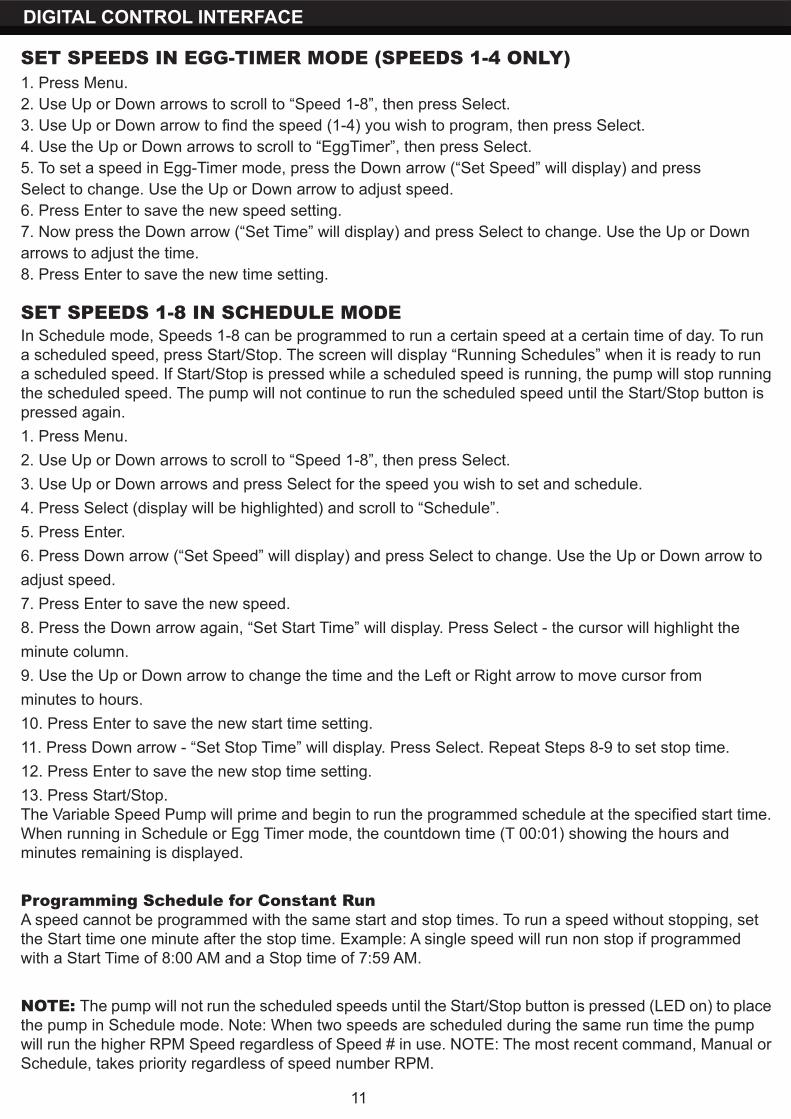
SET SPEEDS IN EGG-TIMER MODE (SPEEDS 1-4 ONLY)1. Press Menu.2. Use Up or Down arrows to scroll to “Speed 1-8”, then press Select.3. Use Up or Down arrow to find the speed (1-4) you wish to program, then press Select.4. Use the Up or Down arrows to scroll to “EggTimer”, then press Select.5. To set a speed in Egg-Timer mode, press the Down arrow (“Set Speed” will display) and pressSelect to change. Use the Up or Down arrow to adjust speed.6. Press Enter to save the new speed setting.7. Now press the Down arrow (“Set Time” will display) and press Select to change. Use the Up or Downarrows to adjust the time.8. Press Enter to save the new time setting.
SET SPEEDS 1-8 IN SCHEDULE MODE In Schedule mode, Speeds 1-8 can be programmed to run a certain speed at a certain time of day. To runa scheduled speed, press Start/Stop. The screen will display “Running Schedules” when it is ready to runa scheduled speed. If Start/Stop is pressed while a scheduled speed is running, the pump will stop runningthe scheduled speed. The pump will not continue to run the scheduled speed until the Start/Stop button ispressed again.1. Press Menu.2. Use Up or Down arrows to scroll to “Speed 1-8”, then press Select.3. Use Up or Down arrows and press Select for the speed you wish to set and schedule.4. Press Select (display will be highlighted) and scroll to “Schedule”.5. Press Enter.6. Press Down arrow (“Set Speed” will display) and press Select to change. Use the Up or Down arrow toadjust speed.7. Press Enter to save the new speed.8. Press the Down arrow again, “Set Start Time” will display. Press Select - the cursor will highlight theminute column.9. Use the Up or Down arrow to change the time and the Left or Right arrow to move cursor fromminutes to hours.10. Press Enter to save the new start time setting.11. Press Down arrow - “Set Stop Time” will display. Press Select. Repeat Steps 8-9 to set stop time.12. Press Enter to save the new stop time setting.13. Press Start/Stop.The Variable Speed Pump will prime and begin to run the programmed schedule at the specified start time.When running in Schedule or Egg Timer mode, the countdown time (T 00:01) showing the hours andminutes remaining is displayed.
Programming Schedule for Constant RunA speed cannot be programmed with the same start and stop times. To run a speed without stopping, setthe Start time one minute after the stop time. Example: A single speed will run non stop if programmedwith a Start Time of 8:00 AM and a Stop time of 7:59 AM.
NOTE: The pump will not run the scheduled speeds until the Start/Stop button is pressed (LED on) to placethe pump in Schedule mode. Note: When two speeds are scheduled during the same run time the pumpwill run the higher RPM Speed regardless of Speed # in use. NOTE: The most recent command, Manual orSchedule, takes priority regardless of speed number RPM.
11
DIGITAL CONTROL INTERFACE
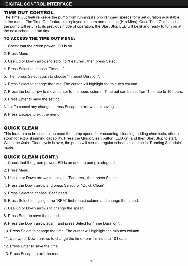
TIME OUT CONTROLThe Time Out feature keeps the pump from running it’s programmed speeds for a set duration adjustable in the menu. The Time Out feature is displayed in hours and minutes (Hrs:Mins). Once Time Out is inished, the pump will return to its previous mode of operation, the Start/Stop LED will be lit and ready to turn on at the next scheduled run time.
TO ACCESS THE TIME OUT MENU:
1. Check that the green power LED is on.
2. Press Menu.
3. Use Up or Down arrows to scroll to “Features”, then press Select.
4. Press Select to choose “Timeout”.
5. Then press Select again to choose “Timeout Duration”.
6. Press Select to change the time. The cursor will highlight the minutes column.
7. Press the Left arrow to move cursor to the hours column. Time out can be set from 1 minute to 10 hours.
8. Press Enter to save the setting.
Note: To cancel any changes, press Escape to exit without saving.
9. Press Escape to exit the menu.
12
QUICK CLEANThis feature can be used to increase the pump speed for vacuuming, cleaning, adding chemicals, after astorm for extra skimming capability. Press the Quick Clean button (LED on) and then Start/Stop to start.When the Quick Clean cycle is over, the pump will resume regular schedules and be in “Running Schedule”mode.
QUICK CLEAN (CONT.)1. Check that the green power LED is on and the pump is stopped.
2. Press Menu.
3. Use Up or Down arrows to scroll to “Features”, then press Select.
4. Press the Down arrow and press Select for “Quick Clean”.
5. Press Select to choose “Set Speed”.
6. Press Select to highlight the “RPM” first (ones) column and change the speed.
7. Use Up or Down arrows to change the speed.
8. Press Enter to save the speed.
9. Press the Down arrow again, and press Select for “Time Duration”.
10. Press Select to change the time. The cursor will highlight the minutes column.
11. Use Up or Down arrows to change the time from 1 minute to 10 hours.
12. Press Enter to save the time.
13. Press Escape to exit the menu.
INSTALLATION
13
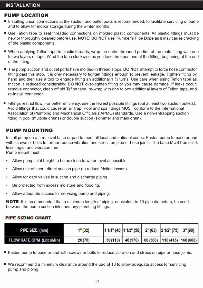
PUMP LOCATIONInstalling union connections at the suction and outlet ports is recommended, to facilitate servicing of pump and to allow for indoor storage during the winter months.
Use Teflon tape to seal threaded connections on molded plastic components. All plastic fittings must be new or thoroughly cleaned before use. NOTE: DO NOT use Plumber’s Pipe Dope as it may cause cracking of the plastic components.
When applying Teflon tape to plastic threads, wrap the entire threaded portion of the male fitting with one to two layers of tape. Wind the tape clockwise as you face the open end of the fitting, beginning at the end of the fitting.
The pump suction and outlet ports have molded-in thread stops. DO NOT attempt to force hose connector fitting past this stop. It is only necessary to tighten fittings enough to prevent leakage. Tighten fitting by hand and then use a tool to engage fitting an additional 1 ½ turns. Use care when using Teflon tape as friction is reduced considerably; DO NOT over-tighten fitting or you may cause damage. If leaks occur, remove connector, clean off old Teflon tape, re-wrap with one to two additional layers of Teflon tape, and re-install connector.
Fittings restrict flow. For better efficiency, use the fewest possible fittings (but at least two suction outlets).Avoid fittings that could cause an air trap. Pool and spa fittings MUST conform to the InternationalAssociation of Plumbing and Mechanical Officials (IAPMO) standards. Use a non-entrapping suctionfitting in pool (multiple drains) or double suction (skimmer and main drain).
PUMP MOUNTINGInstall pump on a firm, level base or pad to meet all local and national codes. Fasten pump to base or padwith screws or bolts to further reduce vibration and stress on pipe or hose joints. The base MUST be solid,level, rigid, and vibration free.Pump mount must:
• Allow pump inlet height to be as close to water level aspossible.
• Allow use of short, direct suction pipe (to reduce friction losses).
• Allow for gate valves in suction and discharge piping.
• Be protected from excess moisture and flooding.
• Allow adequate access for servicing pump and piping.
NOTE: It is recommended that a minimum length of piping, equivalent to 10 pipe diameters, be usedbetween the pump suction inlet and any plumbing fittings.
Fasten pump to base or pad with screws or bolts to reduce vibration and stress on pipe or hose joints.
We recommend a minimum clearance around the pad of 18 to allow adequate access for servicingpump and piping.
INSTALLATION
14
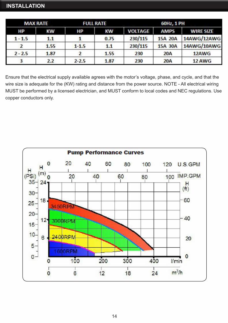
Ensure that the electrical supply available agrees with the motor’s voltage, phase, and cycle, and that thewire size is adequate for the (KW) rating and distance from the power source. NOTE - All electrical wiringMUST be performed by a licensed electrician, and MUST conform to local codes and NEC regulations. Usecopper conductors only.
INSTALLATION
15
Risk of Electric Shock. All electrical wiring MUST be in conformance with applicable local codes, regulations, and the National Electric Code (NEC). All electrical wiring should be performed by a qualified professional. Hazardous voltage can shock, burn, and cause death or serious property damage. To reduce the risk of electric shock, DO NOT use an extension cord to connect unit to electric supply. Provide a properly located electrical receptacle. Before working on any electrical equipment, turn off power supply to the equipment. To reduce the risk of electric shock replace damaged wiring immediately. DO NOT ground to a gas supply line.
The electrical equipment must be connected only to a supply circuit that is protected by a ground-faultcircuit-interrupter (GFCI). Such a GFCI should be provided by the installer and should be tested on a routine basis. To test the GFCI, push the test button. The GFCI should interrupt power. Push reset button. Power should be restored. If the GFCI fails to operate in this manner, the GFCI is defective. If the GFCI interrupts power to the electrical equipment without the test button being pushed, a ground current is flowing, indicating the possibility of an electrical shock. DO NOT use this electrical equipment. Disconnect the electrical equipment and have the problem corrected by a qualified service representative before using. Insure that the electrical supply available agrees with the motor’s voltage, phase, and cycle, and that the wire size is adequate for the KW rating and distance from the power source.
Voltage at motor MUST NOT be more than 10% above or below motor name plate rated voltage, or motor may overheat, causing overload tripping and reduced component life. If voltage is less than 90% or more than 110% of rated voltage when motor is running at full load, consult power company.
Failure to bond all electrical equipment to pool structure will increase risk for electrocution and could result in injury or death. To reduce the risk of electric shock, see installation instructions and consult a professional electrician on how to bond all electrical equipment. Also, contact a licensed electrician forinformation on local electrical codes for bonding requirements.
Pump MUST be permanently connected to circuit. If other lights or appliances are also on the same circuit, be sure to add their amp loads before calculating wire and circuit breaker sizes. Use the load circuit breaker as the Master On-Off switch.
Install a Ground Fault Circuit Interrupter (GFCI) in circuit; it will sense a short-circuit to ground and disconnect power before it becomes dangerous to pool users. For size of GFCI required and test procedures for GFCI, see manufacturer’s instructions. In case of a power outage, check GFCI for tripping, which will prevent normal pump operation. Reset if necessary.
NOTE: If you do not use conduit when wiring motor, be sure to seal wire opening on end of motor to prevent dirt, bugs, etc., from entering.
OPERATION
16
PRIOR TO START-UPNOTE: It is necessary to perform a pressure test prior to initial use to ensure pump is functioning properly.The following criteria should be maintained for this test:1. Have a professional perform this test.2. Ensure all pump and system components are sealed properly to prevent leaks.3. Remove any trapped air in the system by fully opening filter manual air relief valve until a steady streamof water is discharged.4. Allow no more than 40 psi (276 kPa) at a water temperature no higher than 100° F (38° C).5. Run pressure test for no longer than 24 hours. Immediately inspect all parts to verify they are intact and
Fill strainer housing with water to suction pipe level. NEVER OPERATE THE PUMP WITHOUT WATER. Water acts as a coolant and lubricant for the mechanical shaft seal.
NEVER run pump dry. Running pump dry may damage seals, causing leakage, flooding, and voids warranty. Fill strainer housing with water before starting motor.
DO NOT add chemicals to pool/spa system directly in front of pump suction. Adding undiluted chemicals may damage pump and voids warranty.
Before removing strainer cover:1. STOP PUMP before proceeding.2. CLOSE VALVES in suction and outlet pipes.3. RELEASE ALL PRESSURE from pump and piping system using filter manual air relief valve.
WARNING: If pump is being pressure tested (40 PSI MAXIMUM), be sure pressure has been released, using the filter manual air relief valve, before removing strainer cover.
PRIMING THE PUMPCAUTION: All suction and discharge valves MUST be OPEN, as well as filter air relief valve (if available)on filter, when starting the circulating pump system. Failure to do so could result in severe personal injury.
• Release all pressure from filter, pump, and piping system. See filter owner’s manual.• If water source is higher than the pump, pump will prime itself when suction and outlet valves are opened.• If water source is lower than the pump, unscrew and remove strainer cover; fill strainer housing with water.• Clean and lubricate strainer cover O-ring with “Jack’s 327” each time it is removed. Inspect O-ring and• re-install on strainer cover.• Replace strainer cover on strainer housing; turn clockwise to tighten cover.
NOTE: Tighten strainer cover by hand only (no wrenches).
Turn on power and wait for pump to prime, which may take up to five (5) minutes. Priming time will dependon vertical length of suction lift and horizontal length of suction pipe. If pump does NOT prime within fiveminutes, stop motor and determine cause. Be sure all suction and discharge valves are open when pumpis running. See Troubleshooting Guide.
NOTE: Wait five (5) seconds before re-starting pump. Failure to do so may cause reverse rotation of motor and consequent serious pump damage. Close filter manual air relief valve after pump is primed.
17
OPERATION
PUMP WINTERIZATION STORAGEELECTRICAL HAZARD: To avoid dangerous or fatal electrical shock hazard, turn OFF power to motor before draining pump. Drain all water from pump and piping when expecting freezing temperatures or when storing pump.
1. Drain water level below all inlets to the pool.
2. Remove drain plug from bottom of strainer body.
3. Disconnect pump from base.
4. Once the pump is drained of water, re-install the strainer lid and strainer plug.
5. Store pump in a dry enclosure. Keep motor dry and covered during storage. To avoid condensation/corrosion problems. DO NOT cover or wrap pump with plastic film or bags.
1. Securely mount pump to base.2. Install all intake and output fittings and piping.3. Refill pool to proper water level.4. Prime pump according to instructions.
START-UP FOR WINTERIZED EQUIPMENT
SHAFT SEAL CHANGE INSTRUCTIONSOnly qualified personnel should attempt rotary seal replacement. Risk of Electric Shock Failure to turn off power can cause serious or fatal electrical shock hazard. Disconnect all electrical power service to pump before beginning shaft seal replacement.
Exercise extreme care in handling both the rotating and the stationary sections of the two-part replacement seal. Foreign matter or improper handling will easily scratch the graphite and ceramic sealing surfaces.
Clean strainer basket regularly. DO NOT strike basket to clean. Inspect strainer cover gasket regularly and replace as necessary.
Pumps have self-lubricating motor bearings and shaft seals. No lubrication is necessary.
Keep motor clean. Insure air vents are free from obstruction to avoid damage. DO NOT use water to hose off motor.
Occasionally, shaft seals must be replaced, due to wear or damage. Replace with genuine Hayward seal assembly kit.
MAINTENANCE
EXPLOSION HAZARD: Purging the system with compressed air can cause components to explode, with risk of severe injury or death to anyone nearby. Use only a low pressure (below 5 PSI), high volume blower when air purging the pump, filter, or piping.
Allowing the pump to freeze will void the warranty.
DO NOT use anti-freeze solutions (except propylene glycol) in your pool/spa system. Propylene glycol is non-toxic and will not damage plastic system components; other anti-freezes are highly toxic and may damage plastic components in the system. Gravity drain system as far as possible.
OPERATION
1. Shut off water flow to pump by closing appropriate valves or by plugging both the skimmer outlet port and return port to pool. Disconnect piping or hoses from the motor/pump assembly.
2. Remove the strainer by disengaging and removing the strainer cover. Remove the basket. Lift up on strainer ‘C’ clip and remove. Finally, slide strainer housing forward and remove.
3. Unscrew screws and remove pump cover, exposing the impeller.
4. Remove the canopy or the shaft cover plate from the end of motor opposite the impeller.
5. Hold the motor shaft securely by either inserting a screwdriver in slot at end of shaft or by using an open-end wrench to engage the flat surfaces provided near end of motor shaft. Rotate the impeller in a counter-clockwise direction and remove it from the motor shaft.
6. Note how the steel spring section of the old seal is positioned on impeller hub and remove it by pulling from the impeller.
7. Loosen motor through bolts from the back of motor and remove pump housing/shroudfrom the front of the motor.
8. Remove the ceramic stationary portion of the old seal by pressing the white ceramic seatout of the pump housing recess. If assembly is tight, tap lightly from the “motor” side.
9. Clean and lubricate the impeller stem and the pump housing recess with a dilute solution of non-granulated liquid type soap. Do not use petroleum or silicone lubricants as these can contribute to seal leakage.
10. Press the new rotating portion of the seal assembly onto the impeller stem with the polished black graphite surface facing away from the impeller.
11. Carefully press the stationary ceramic portion of the seal into the recess of the pumphousing/shroud, with the polished flat surface facing out.
12. Carefully insert the motor shaft through the pump housing/shroud and align with white ceramic stationary seal assembly in place and secure the motor to pump housing/shroud with motor through bolts. Be sure motor base and pump discharge port are positioned properly. Alternately tighten the motor through bolts until the pump housing is secure. Make certain motor shaft turns freely before proceeding.
13. Screw the impeller (clockwise) with the rotating portion of seal in place onto the motor shaft. Handtighten the impeller in place.
14. Clean (replace if necessary) the O-ring and replace on pump cover. Assemble the pumpcover to the pump housing/ shroud with the screws. Tighten screws alternately and evenly.
15. Re-assemble strainer by sliding strainer housing onto pump cover. Install strainer ‘C’ clip by pushing clip down onto grooved pump cover coupling. Insert basket and fasten strainer cover.
16. Reconnect pump to the piping or hoses provided. Open all valves and make sure that the pump strainer housing is full of water before restarting the pump.
SHAFT SEAL CHANGE INSTRUCTIONS
18
TROUBLESHOOTING
ALERTS AND WARNINGS
The Variable Speed Pump displays all alarms and warnings on the control panel display. When an alarm or warning condition exists, the corresponding light will be lit on the display. All control panel buttons are disabled until the alarm or warning is acknowledged with the Reset button. Pressing the Reset button will clear the alarm once the fault condition has been resolved.
NOTE: The pump will not start if the impeller is rotating.
POWER OUT/OFFThe incoming supply voltage is less than 170 VAC. The drive faults to protect itself from over current. The drive contains capacitors that keep it powered up long enough to save the current run parameters. If power is restored during this process, approximately 20 seconds, the drive will not restart until completed.
OVERHEATIf the drive temperature gets above 54.4° C (130° F) the pump will slowly reduce speed until the over temperature condition clears.
OVER CURRENTIndicated that the drive is overloaded or the motor has an electrical problem. The drive will restart 20 seconds after the over current condition clears.
OVER VOLTAGEIndicates excessive supply voltage or an external water source is causing the pump and motor to rotate thereby generating an excessive voltage on the drives internal DC buss. The drive will restart 20 seconds after the over voltage condition clears.
INTERNAL ERRORIndicates that the self-monitoring motor control software has encountered an error. Clear the alarm and restart the pump.
19
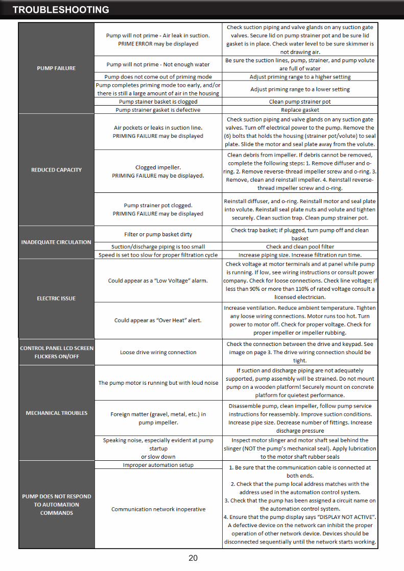
TROUBLESHOOTING
20
21
MAINTENANCE
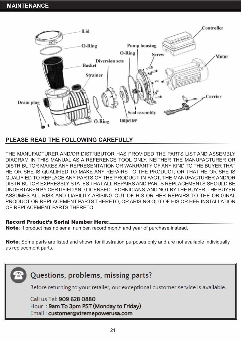
THE MANUFACTURER AND/OR DISTRIBUTOR HAS PROVIDED THE PARTS LIST AND ASSEMBLY DIAGRAM IN THIS MANUAL AS A REFERENCE TOOL ONLY. NEITHER THE MANUFACTURER OR DISTRIBUTOR MAKES ANY REPRESENTATION OR WARRANTY OF ANY KIND TO THE BUYER THAT HE OR SHE IS QUALIFIED TO MAKE ANY REPAIRS TO THE PRODUCT, OR THAT HE OR SHE IS QUALIFIED TO REPLACE ANY PARTS OF THE PRODUCT. IN FACT, THE MANUFACTURER AND/OR DISTRIBUTOR EXPRESSLY STATES THAT ALL REPAIRS AND PARTS REPLACEMENTS SHOULD BE UNDERTAKEN BY CERTIFIED AND LICENSED TECHNICIANS, AND NOT BY THE BUYER. THE BUYER ASSUMES ALL RISK AND LIABILITY ARISING OUT OF HIS OR HER REPAIRS TO THE ORIGINAL PRODUCT OR REPLACEMENT PARTS THERETO, OR ARISING OUT OF HIS OR HER INSTALLATION OF REPLACEMENT PARTS THERETO.
Record Product’s Serial Number Here:Note: If product has no serial number, record month and year of purchase instead.
Note: Some parts are listed and shown for illustration purposes only and are not available individually as replacement parts.
PLEASE READ THE FOLLOWING CAREFULLY