Embed Size (px)
DESCRIPTION
15800 DWDM System Technical Specs
Citation preview

Corporate HeadquartersCisco Systems, Inc.170 West Tasman DriveSan Jose, CA 95134-1706 USAhttp://www.cisco.comTel: 408 526-4000
800 553-NETS (6387)Fax: 408 526-4100
Cisco ONS 15800 DWDM System Technical Specifications ManualHardware Release 1.6
April 2002
Text Part Number: 78-13141-03

THE SPECIFICATIONS AND INFORMATION REGARDING THE PRODUCTS IN THIS MANUAL ARE SUBJECT TO CHANGE WITHOUT NOTICE. ALL STATEMENTS, INFORMATION, AND RECOMMENDATIONS IN THIS MANUAL ARE BELIEVED TO BE ACCURATE BUT ARE PRESENTED WITHOUT WARRANTY OF ANY KIND, EXPRESS OR IMPLIED. USERS MUST TAKE FULL RESPONSIBILITY FOR THEIR APPLICATION OF ANY PRODUCTS.
THE SOFTWARE LICENSE AND LIMITED WARRANTY FOR THE ACCOMPANYING PRODUCT ARE SET FORTH IN THE INFORMATION PACKET THAT SHIPPED WITH THE PRODUCT AND ARE INCORPORATED HEREIN BY THIS REFERENCE. IF YOU ARE UNABLE TO LOCATE THE SOFTWARE LICENSE OR LIMITED WARRANTY, CONTACT YOUR CISCO REPRESENTATIVE FOR A COPY.
Modifications to this product not authorized by Cisco Systems, Inc. could void the FCC approval and negate your authority to operate the product.
The Cisco implementation of TCP header compression is an adaptation of a program developed by the University of California, Berkeley (UCB) as part of UCB’s public domain version of the UNIX operating system. All rights reserved. Copyright © 1981, Regents of the University of California.
NOTWITHSTANDING ANY OTHER WARRANTY HEREIN, ALL DOCUMENT FILES AND SOFTWARE OF THESE SUPPLIERS ARE PROVIDED “AS IS” WITH ALL FAULTS. CISCO AND THE ABOVE-NAMED SUPPLIERS DISCLAIM ALL WARRANTIES, EXPRESSED OR IMPLIED, INCLUDING, WITHOUT LIMITATION, THOSE OF MERCHANTABILITY, FITNESS FOR A PARTICULAR PURPOSE AND NONINFRINGEMENT OR ARISING FROM A COURSE OF DEALING, USAGE, OR TRADE PRACTICE.
IN NO EVENT SHALL CISCO OR ITS SUPPLIERS BE LIABLE FOR ANY INDIRECT, SPECIAL, CONSEQUENTIAL, OR INCIDENTAL DAMAGES, INCLUDING, WITHOUT LIMITATION, LOST PROFITS OR LOSS OR DAMAGE TO DATA ARISING OUT OF THE USE OR INABILITY TO USE THIS MANUAL, EVEN IF CISCO OR ITS SUPPLIERS HAVE BEEN ADVISED OF THE POSSIBILITY OF SUCH DAMAGES.
AccessPath, AtmDirector, Browse with Me, CCDA, CCDE, CCDP, CCIE, CCNA, CCNP, CCSI, CD-PAC, CiscoLink, the Cisco NetWorks logo, the Cisco Powered Network logo, Cisco Systems Networking Academy, the Cisco Systems Networking Academy logo, Fast Step, Follow Me Browsing, FormShare, FrameShare, GigaStack, IGX, Internet Quotient, IP/VC, iQ Breakthrough, iQ Expertise, iQ FastTrack, the iQ Logo, iQ Net Readiness Scorecard, MGX, the Networkers logo, Packet, RateMUX, ScriptBuilder, ScriptShare, SlideCast, SMARTnet, TransPath, Unity, Voice LAN, Wavelength Router, and WebViewer are trademarks of Cisco Systems, Inc.; Changing the Way We Work, Live, Play, and Learn, Discover All That’s Possible, and Empowering the Internet Generation, are service marks of Cisco Systems, Inc.; and Aironet, ASIST, BPX, Catalyst, Cisco, the Cisco Certified Internetwork Expert logo, Cisco IOS, the Cisco IOS logo, Cisco Systems, Cisco Systems Capital, the Cisco Systems logo, Enterprise/Solver, EtherChannel, EtherSwitch, FastHub, FastSwitch, IOS, IP/TV, LightStream, MICA, Network Registrar, PIX, Post-Routing, Pre-Routing, Registrar, StrataView Plus, Stratm, SwitchProbe, TeleRouter, and VCO are registered trademarks of Cisco Systems, Inc. and/or its affiliates in the U.S. and certain other countries.
All other brands, names, or trademarks mentioned in this document or Web site are the property of their respective owners. The use of the word partner does not imply a partnership relationship between Cisco and any other company. (0104R)
Cisco ONS 15800 DWDM System Technical Specifications ManualCopyright © 2002, Cisco Systems, Inc.All rights reserved.

iiiCisco ONS 15800 DWDM System Technical Specifications Manual
78-13141-03
C O N T E N T S
Preface xiii
Safety Summary xiii
General Safety Precautions xiii
Electrical Safety Precautions xiii
Optical Safety Precautions xiv
Laser Safety Features xv
ESD Precautions xvi
Safety Symbols and Labels xvi
Area Warning Sign xvi
Electrical Safety Labels xvii
Front and Back Door Safety Labels xvii
Subrack Safety Labels xviii
Module Safety Labels xix
Conventions xx
Documentation InfoSet Structure xxi
Obtaining Documentation xxii
World Wide Web xxii
Ordering Documentation xxii
Documentation Feedback xxii
Obtaining Technical Assistance xxiii
Cisco.com xxiii
Technical Assistance Center xxiii
Contacting TAC by Telephone xxiv
Contacting TAC Using the Cisco TAC Website xxiv
C H A P T E R 1 Introduction 1-1
Purpose of This Publication 1-1
Manual Structure 1-1
References 1-1
Applicable Standards 1-1
Additional ONS 15800 System Information 1-2
Related Standards About Wavelength Division Multiplexing 1-3
Revision History 1-4

Contents
ivCisco ONS 15800 DWDM System Technical Specifications Manual
78-13141-03
C H A P T E R 2 System Performance 2-1
Performance Characteristics 2-1
Band Separation Principle 2-1
Channel Allocations and Span Budgets 2-1
Blue-Band Channel Allocation 2-2
Red-Band Channel Allocation 2-2
Span Budgets 2-3
Channel Counts and Span Budgets for 2.5-Gbps Operation 2-3
Channel Counts and Span Budgets for 10-Gbps Operation 2-5
C H A P T E R 3 Module Specifications 3-1
Active Modules 3-1
Line Extender Module–Externally Modulated–B1 Monitoring 3-3
Line Extender Module–Externally Modulated–Forward Error Correction 3-4
Line Extender Module–10 Gbps–B1 Monitoring 3-5
Line Extender Module–10 Gbps High Output Power–B1 Monitoring Module 3-6
Line Extender Module–10 Gbps–Forward Error Correction 3-7
Receive Transponder–Directly Modulated–B1 Monitoring Module 3-8
Receive Transponder–Directly Modulated– Forward Error Correction Module 3-9
Receive Transponder–10 Gbps–B1 Monitoring Module 3-10
Receive Transponder–10 Gbps–Forward Error Correction Module 3-11
Wavelength Converter Module–Externally Modulated–B1 Monitoring 3-12
Wavelength Converter Module–Externally Modulated– Forward Error Correction 3-14
Wavelength Converter Module–10 Gbps–B1 Monitoring 3-15
Wavelength Converter Module–10 Gbps High Output Power–B1 Monitoring 3-16
Wavelength Converter Module–10 Gbps–Forward Error Correction 3-17
Add Drop Amplifier Module 3-18
Blue-band Booster Amplifier Module 3-19
Blue-band Booster Amplifier–10 Gbps Module 3-20
Pre-Line Amplifier Module 3-22
Red-band Booster Amplifier Module 3-23
Red-band Booster Amplifier–10 Gbps Module 3-24
Transmit Power Amplifier–Blue Band Module 3-26
Transmit Power Amplifier–Red Band Module 3-27
Optical Add/Drop Multiplexer Module 3-29
8-channel Wavelength Demultiplexer–Blue Band Module 3-30
24-channel Wavelength Demultiplexer–Red Band Module 3-31
24-channel Wavelength Demultiplexer–Low Loss–Red Band Module 3-31
Common Modules 3-32

Contents
vCisco ONS 15800 DWDM System Technical Specifications Manual
78-13141-03
Battery Management Module 3-33
Control and Monitoring Processor Modules 3-34
Subrack Common Functions Module 3-34
External Orderwire Interface Module 3-35
Input/Output Card Module 3-36
Line Service Modem Module 3-36
Router Bridge Unit Module 3-37
Passive Modules 3-38
1-channel Pass-through Module 3-38
8-channel Wavelength Multiplexer–Blue Band Module 3-38
24-channel Wavelength Multiplexer–Red Band Module 3-39
Dispersion Compensating Unit Module 3-40
Optical Service Channel–Pass-Through Module 3-41
Auxiliary Components 3-41
Gain-Flattening Filter–Red Band 3-41
C H A P T E R 4 Supervision and Alarms 4-1
Supervisory Modules 4-1
Control and Monitoring Processor Module 4-1
Subrack Common Functions Module 4-1
Performance Management 4-2
Local Craft Interface 4-3
Housekeeping Alarm Management 4-3
Module Alarms 4-3
C H A P T E R 5 Engineering Specifications 5-1
Mechanical 5-1
Physical Layout 5-1
Optical Subrack 5-3
Optical Subrack–Multiplexer 5-3
Optical Subrack–Dispersion Compensating Unit 5-4
Module Insertion 5-4
Dimensions 5-4
Electrical 5-5
Power Supply 5-5
Grounding 5-5
Power Consumption 5-5
Environmental 5-5

Contents
viCisco ONS 15800 DWDM System Technical Specifications Manual
78-13141-03
Reliability 5-6
Optical 5-7
Optical Connectors 5-8
Optical Safety and Protection 5-8
Safety 5-8
Electromagnetic Compatibility 5-9
Access 5-9
Marking 5-9
F I G U R E S
viiCisco ONS 15800 DWDM System Technical Specifications Manual
78-13141-03
Figure 1 Cisco ONS 15800/15801 System Startup Warning xv
Figure 2 Sample Laser-Controlled Area Warning Sign xvi
Figure 3 Electrical Energy Hazard Symbol xvii
Figure 4 Attention Symbol xvii
Figure 5 Danger Label on Front and Back Doors of Cisco ONS 15800 Subracks xvii
Figure 6 Danger Label on Front and Back Doors of Cisco ONS 15801 Subracks xviii
Figure 7 ONS 15800 System Backplane Safety Label xviii
Figure 8 ONS 15801 System Backplane Safety Label xviii
Figure 9 Backplane Aperture Laser Safety Label xix
Figure 2-1 Transmission Window Bands 2-1
Figure 5-1 Sample Bay Configuration of Modules in Subracks 5-2
Figure 5-2 OSR-W Subrack Physical Layout 5-3
Figure 5-3 OSR-MUX Subrack Physical Layout 5-4
Figure 5-4 OSR-DCU Subrack Physical Layout 5-4

Figures
viiiCisco ONS 15800 DWDM System Technical Specifications Manual
78-13141-03
T A B L E S
ixCisco ONS 15800 DWDM System Technical Specifications Manual
78-13141-03
Table 2-1 Allocation of Blue Band Channels 2-2
Table 2-2 Allocation of Red Band Channels 2-2
Table 3-3 LEM-EM-Mxx Module Electrical Characteristics 3-4
Table 3-4 LEM-EM-Mxx Module Mechanical Characteristics 3-4
Table 3-6 LEM-EM-Fxx Module Electrical Characteristics 3-5
Table 3-7 LEM-EM-Fxx Module Mechanical Characteristics 3-5
Table 3-9 LEM-10G-Mxx Module Electrical Characteristics 3-6
Table 3-10 LEM-10G-Mxx Module Mechanical Characteristics 3-6
Table 3-12 LEM-10H-Mxx Module Electrical Characteristics 3-7
Table 3-13 LEM-10H-Mxx Module Mechanical Characteristics 3-7
Table 3-15 LEM-10G-Fxx Module Electrical Characteristics 3-8
Table 3-16 LEM-10G-Fxx Module Mechanical Characteristics 3-8
Table 3-18 RXT-DM-M Module Electrical Characteristics 3-9
Table 3-19 RXT-DM-M Module Mechanical Characteristics 3-9
Table 3-21 RXT-DM-F Module Electrical Characteristics 3-10
Table 3-22 RXT-DM-F Module Mechanical Characteristics 3-10
Table 3-24 RXT-10G-M Module Electrical Characteristics 3-11
Table 3-25 RXT-10G-M Module Mechanical Characteristics 3-11
Table 3-27 RXT-10G-F Module Electrical Characteristics 3-12
Table 3-28 RXT-10G-F Module Mechanical Characteristics 3-12
Table 3-30 WCM-EM-Mxx Module Electrical Characteristics 3-13
Table 3-31 WCM-EM-Mxx Module Mechanical Characteristics 3-13
Table 3-33 WCM-EM-Fxx Module Electrical Characteristics 3-14
Table 3-34 WCM-EM-Fxx Module Mechanical Characteristics 3-14
Table 3-36 WCM-10G-Mxx Module Electrical Characteristics 3-15
Table 3-37 WCM-10G-Mxx Module Mechanical Characteristics 3-15
Table 3-39 WCM-10H-Mxx Module Electrical Characteristics 3-16
Table 3-40 WCM-10H-Mxx Module Mechanical Characteristics 3-17
Table 3-42 WCM-10G-Fxx Module Electrical Characteristics 3-17
Table 3-43 WCM-10G-Fxx Module Mechanical Characteristics 3-18
Table 3-45 ADA Module Electrical Characteristics 3-19

Tables
xCisco ONS 15800 DWDM System Technical Specifications Manual
78-13141-03
Table 3-46 ADA Module Mechanical Characteristics 3-19
Table 3-48 BBA Module Electrical Characteristics 3-20
Table 3-49 BBA Module Mechanical Characteristics 3-20
Table 3-51 BBA-10G Module Electrical Characteristics 3-21
Table 3-52 BBA-10G Module Mechanical Characteristics 3-21
Table 3-54 PRE-L Module Electrical Characteristics 3-22
Table 3-55 PRE-L Module Mechanical Characteristics 3-23
Table 3-57 RBA Module Electrical Characteristics 3-24
Table 3-58 RBA Module Mechanical Characteristics 3-24
Table 3-60 RBA-10G Module Electrical Characteristics 3-25
Table 3-61 RBA-10G Module Mechanical Characteristics 3-25
Table 3-63 TPA-B Module Electrical Characteristics 3-27
Table 3-64 TPA-B Module Mechanical Characteristics 3-27
Table 3-66 TPA-R Module Electrical Characteristics 3-28
Table 3-67 TPA-R Module Mechanical Characteristics 3-28
Table 3-69 OADM-P4 Module Electrical Characteristics 3-29
Table 3-70 OADM-P4 Module Mechanical Characteristics 3-29
Table 3-72 8WD-B Module Electrical Characteristics 3-30
Table 3-73 8WD-B Module Mechanical Characteristics 3-30
Table 3-75 24WD-R Module Electrical Characteristics 3-31
Table 3-76 24WD-R Module Mechanical Characteristics 3-31
Table 3-78 24WD-LLR Module Electrical Characteristics 3-32
Table 3-79 24WD-LLR Module Mechanical Characteristics 3-32
Table 3-80 Common Modules 3-33
Table 3-82 BAT Module Mechanical Characteristics 3-34
Table 3-83 CMP-W and CMP-W-2E Module Electrical Characteristics 3-34
Table 3-84 CMP-W and CMP-W-2E Module Mechanical Characteristics 3-34
Table 3-85 SCF Module Electrical Characteristics 3-35
Table 3-86 SCF Module Mechanical Characteristics 3-35
Table 3-87 EOI-W Module Electrical Characteristics 3-35
Table 3-88 EOI-W Module Mechanical Characteristics 3-35
Table 3-89 EOI-W Interface Specifications 3-36
Table 3-90 IOC-W Module Electrical Characteristics 3-36
Table 3-91 IOC-W Module Mechanical Characteristics 3-36
Table 3-93 LSM-W Module Electrical Characteristics 3-37

Tables
xiCisco ONS 15800 DWDM System Technical Specifications Manual
78-13141-03
Table 3-94 LSM-W Module Mechanical Characteristics 3-37
Table 3-95 RBU Module Electrical Characteristics 3-37
Table 3-96 RBU Module Mechanical Characteristics 3-38
Table 3-97 1PT-W Module Optical Characteristics 3-38
Table 3-98 1PT-W Module Mechanical Characteristics 3-38
Table 3-100 8WM-B Module Mechanical Characteristics 3-39
Table 3-102 24WM-R Module Mechanical Characteristics 3-40
Table 3-103 DCU-B and DCU-R Module Operating Wavelengths 3-40
Table 3-104 DCU-B and DCU-R Module Variation Over Operating Temperature Range 3-40
Table 3-105 DCU-B and DCU-R Module Mechanical Characteristics 3-40
Table 3-106 OSC-PT-W Module Mechanical Characteristics 3-41
Table 4-1 Performance Management Parameters 4-2
Table 4-3 8WD-B Module Digital Alarms 4-4
Table 4-5 24WD-LLR Module Digital Alarms 4-4
Table 4-7 24WD-R Module Digital Alarms 4-5
Table 4-10 BBA Module Digital Alarms 4-6
Table 4-12 BBA-10G Module Digital Alarms 4-8
Table 4-13 EOI-W Module Digital Alarm 4-8
Table 4-14 IOC-W Module Analog Alarms 4-8
Table 4-15 IOC-W Module Digital Alarms 4-8
Table 4-17 LEM-EM-Mxx Module Digital Alarms 4-9
Table 4-19 LEM-EM-Fxx Module Digital Alarms 4-10
Table 4-21 LEM-10G-Mxx Module Digital Alarms 4-11
Table 4-23 LEM-10H-Mxx Module Digital Alarms 4-11
Table 4-25 LEM-10G-Fxx Module Digital Alarms 4-12
Table 4-27 LSM-W Module Digital Alarms 4-13
Table 4-29 OADM-P4 Module Digital Alarms 4-14
Table 4-30 OSU-W Module Default Parameter Settings 4-14
Table 4-32 PRE-L Module Digital Alarms 4-15
Table 4-34 RBA Module Digital Alarms 4-16
Table 4-36 RBA-10G Module Digital Alarms 4-18
Table 4-37 RBU Module Control 4-18
Table 4-39 RXT-DM-M Module Digital Alarms 4-19
Table 4-41 RXT-DM-F Module Digital Alarms 4-20
Table 4-43 RXT-10G-M Module Digital Alarms 4-20

Tables
xiiCisco ONS 15800 DWDM System Technical Specifications Manual
78-13141-03
Table 4-45 RXT-10G-F Module Digital Alarms 4-21
Table 4-47 TPA-B Module Digital Alarms 4-23
Table 4-49 TPA-R Module Digital Alarms 4-24
Table 4-51 WCM-EM-Mxx Module Digital Alarms 4-25
Table 4-53 WCM-EM-Fxx Module Digital Alarms 4-26
Table 4-55 WCM-10G-Mxx Module Digital Alarms 4-27
Table 4-57 WCM-10H-Mxx Module Digital Alarms 4-27
Table 4-59 WCM-10G-Fxx Module Digital Alarms 4-28
Table 5-2 ONS 15800 Ground Characteristics 5-5
Table 5-3 ONS 15800 System Environmental Characteristics 5-6
Table 5-4 Reliability Data for ONS 15800 Modules 5-6

xiiiCisco ONS 15800 DWDM System Technical Specifications Manual
78-13141-03
Preface
This section provides the following information:
• Safety Summary—Safety precautions and safety labeling for the Cisco ONS 15800/15801 system
• Conventions—Writing conventions used throughout the documentation InfoSet
• Documentation InfoSet Structure—Description of the documents contained in the InfoSet
• Obtaining Documentation—Information on how to obtain product documentation
• Obtaining Technical Assistance—Information on how to obtain technical assistance
Safety SummaryThis section covers safety considerations to ensure safe operation of the Cisco ONS 15800/15801 system. Personnel should not perform any procedures in this manual unless they understand all safety precautions, practices, and warnings for the system equipment.
General Safety PrecautionsThe following general safety precautions are not related to any specific procedures and do not appear elsewhere in this publication. These are recommended precautions that personnel must understand and apply during installation, testing, and use of the Cisco ONS 15800/15801 system.
• Know and understand electrical safety, wiring, and connection practices.
• Be familiar with modern methods of resuscitation. This information can be obtained from the Red Cross or its local equivalent. This knowledge is imperative for personnel working with or near equipment with voltage levels capable of causing injury or death.
Electrical Safety PrecautionsThe following electrical safety precautions, procedures, and rules are required when working on the Cisco ONS 15800/15801 system:
• The Cisco ONS 15800/15801 system must be connected to a power supply that never exceeds voltage limits.
• The Cisco ONS 15800/15801 system power must be supplied by a power supply system with reinforced insulation.
xivCisco ONS 15800 DWDM System Technical Specifications Manual
78-13141-03
PrefaceSafety Summary
• The Cisco ONS 15800/15801 system must be installed and used in a controlled access location. Access must be limited to service personnel and users that have been instructed about the reasons for the controlled access and any precautions that must be taken.
• Touching electrical connectors or other exposed electrical circuitry inside the system subracks can cause injury to personnel.
• All doors must be closed and locked when the equipment is switched ON.
• A disconnection device (fuse) must be present on the power supply line. The power supply line fuse must be removed before wiring.
• The power supply line fuse must be removed before disconnecting the earth ground for maintenance or installation purposes.
• Do not touch anything inside the subrack or introduce anything into the subrack (except modules) when it is turned ON. If module removal is necessary, replace the empty slot with a blank panel immediately.
• All Cisco ONS 15800/15801 system electrical interfaces are intended to be connected to local devices, that is, devices in the same room or in the same building as the ONS 15800/15801 system (not in unprotected environments).
Optical Safety PrecautionsThe following optical safety precautions, procedures, and rules are required when working on the Cisco ONS 15800/15801 system:
• Terminate all fiber outputs properly before connecting fiber inputs.
• Disconnect the fiber input connector before disconnecting the fiber output connector. Ensure that the fiber output is safely terminated before reconnecting the fiber input.
• Handle glass fiber with care. It is subject to breakage if mishandled. Permanent equipment damage can result from using broken fiber.
• Protect skin from exposed glass fiber. It can penetrate the skin.
• Limit personnel having access to light-wave transmission systems. These personnel are to be authorized and properly trained if access to laser emission is required.
• Limit the use of laser test equipment to authorized, trained personnel during installation and service. This precaution includes using the optical loss test set and the optical time domain reflectometer equipment.
• Exclude all unauthorized personnel from the immediate laser radiation area during service and installation when there is a possibility that the system may become energized. Consider the immediate service area to be a temporary laser-controlled area.
• Cisco laser equipment functions in the 1550-nm window, which is considered invisible radiation. Personnel cannot see the laser light being emitted by a fiber, a pigtail, or a bulkhead connector. Use appropriate eye protection during fiber optic system installation or maintenance whenever there is potential for laser exposure, as recommended by health and safety procedures. Observe this precaution, appropriate to the class of equipment, whether warning labels have or have not been posted.
• Eye protection must meet a wavelength specification of 800 to 1800 nm and have an optical density greater than two. Protective glasses such as the Laser-Gard Green CO2 (LGE Spectacle, LGS Goggle, LGW wraparound, or LGF Full-View) or an equivalent type of covering equipment is recommended.

xvCisco ONS 15800 DWDM System Technical Specifications Manual
78-13141-03
PrefaceSafety Summary
Laser Safety FeaturesWhen a fiber break or cut occurs in the Cisco ONS 15800/15801 system, the automatic laser shutdown feature activates. An optical safety circuit reduces optical power to a safer level in the direction toward the fiber break. This optical power is reduced to a Class I hazard within one second of break detection. At the Class I level, the system is considered safe. Once the system reaches the output power shutdown condition triggered by the automatic laser shutdown, the optical system signal can be manually restarted.
Caution When restarting the system manually, such as after an automatic laser shutdown, avoid using an optical power level capable of causing any potential hazard until the line disruption has been eliminated. The output power must be maintained under the Class IIIa upper limit.
A software code is required to turn on the laser in the manual startup procedure. In accordance with safety rules, a dialog box like the one in Figure 1 appears with warning messages about laser radiation.
Figure 1 Cisco ONS 15800/15801 System Startup Warning
When the system is manually restarted after broken fiber is repaired:
• The manual startup turns the units on in a reduced class (I or IIIa).
• The safety override operates at a reduced power level for installation and maintenance.
• Optical power increases to the maximum only if the line continuity is verified from the system interlocking procedure.
Protections against accidental exposure to dangerous optical radiation during the startup procedure include:
• The required startup software code
• The interlocks provided by optical connectors
• The automatic laser shutdown feature
• Proper training for personnel with access to restricted locations
COMMAND EXECUTIONWILL ACTIVATE
LASER RADIATION
AVOID EXPOSURE TO BEAM
Execute Cancel
6427
8

xviCisco ONS 15800 DWDM System Technical Specifications Manual
78-13141-03
PrefaceSafety Summary
ESD PrecautionsSome Cisco ONS 15800/15801 components are classified as Class 0 ESD-sensitive devices. Follow these rules when handling ESD-sensitive devices:
• Assume that all solid-state electronic devices are ESD-sensitive.
• Use a grounded wrist strap (or equivalent equipment) while working with ESD-sensitive devices.
• Transport, store, and handle ESD-sensitive devices in static-safe environments.
Safety Symbols and LabelsCisco ONS 15800/15801 equipment is clearly labeled with warnings about the equipment radiation level. All warning labels must be read and understood by personnel before working with the equipment. Cisco ONS 15800/15801 systems transmitting 10-Gbps channels operate with higher optical power than systems transmitting 2.5-Gbps channels. The warning labels differ for these transmission speeds and power levels.
Area Warning Sign
Signs explaining the existence of a potential laser hazard should be posted prominently at the entrance to the service area and in the vicinity of the installation area where laser-furnished fiber optic equipment is installed, in accordance with IEC 60825. Since the service area is a temporary laser-controlled area, these signs should signal that access is limited to authorized personnel. A sample sign is illustrated in Figure 2. The symbol for a laser hazard is to be prominently displayed at the top of this sign.
Figure 2 Sample Laser-Controlled Area Warning Sign
Controlled Laser AreaAccess by unauthorized staff is not permitted.
Protective eyeglasses must be worn in this area.
6428
3

xviiCisco ONS 15800 DWDM System Technical Specifications Manual
78-13141-03
PrefaceSafety Summary
Electrical Safety Labels
The Cisco ONS 15800/15801 equipment is labeled with hazard symbols to alert personnel to electrical hazards. Additionally, the Cisco ONS 15800/15801 equipment is labeled with attention symbols to alert personnel to potential hazards.
The electrical energy hazard symbol alerts personnel to electrical hazards within the Cisco ONS 15800/15801 system equipment. The potential for electrical hazards exists when equipment doors are open, when power supply cables are disconnected, and when a module is removed and replaced. The electrical energy hazard symbol is illustrated in Figure 3.
Figure 3 Electrical Energy Hazard Symbol
The attention symbol label alerts personnel to exercise caution while working on the Cisco ONS 15800/15801 system. The attention symbol is illustrated in Figure 4.
Figure 4 Attention Symbol
Front and Back Door Safety Labels
The doors of the Cisco ONS 15800/15801 system subracks are labeled with laser radiation warnings. The front and back doors of subracks have danger labels similar to the ones shown in Figures 5 and 6.
Figure 5 Danger Label on Front and Back Doors of Cisco ONS 15800 Subracks
6428
764
288
INVISIBLE LASER RADIATIONAVOID DIRECT EXPOSURE TO BEAM
Maximum output power 50 mWWavelength range 1280-1605 nm
Avoid exposure - invisible laser radiation isemitted from optical connectors
This product conforms to all applicablestandards under 21 CFR 1040.10
WARNINGFOLLOW INSTRUCTIONS OF TECHNICAL MANUAL
DO NOT DISCONNECT OUTPUT WHEN LASER IS ONDO NOT SWITCH ON LASER UNLESS OUTPUT IS CONNECTED
CLASS IIIb LASER PRODUCT
268

xviiiCisco ONS 15800 DWDM System Technical Specifications Manual
78-13141-03
PrefaceSafety Summary
Figure 6 Danger Label on Front and Back Doors of Cisco ONS 15801 Subracks
Subrack Safety Labels
The backplanes of the Cisco ONS 15800/15801 subracks are also labeled to warn against exposure to laser radiation. The backplanes have danger labels similar to the ones shown in Figures 7 and 8.
Figure 7 ONS 15800 System Backplane Safety Label
Figure 8 ONS 15801 System Backplane Safety Label
6428
5
INVISIBLE LASER RADIATIONAVOID DIRECT EXPOSURE TO BEAM
Maximum output power 50 mWWavelength range 1280-1605 nm
CLASS IIIb LASER PRODUCT
Avoid exposure - invisible laser radiation isemitted from optical connectors
This product conforms to all applicablestandards under 21 CFR 1040.10
WARNINGFOLLOW INSTRUCTIONS OF TECHNICAL MANUAL
DO NOT DISCONNECT OUTPUT WHEN LASER IS ONDO NOT SWITCH ON LASER
UNLESS OUTPUT IS CONNECTED
6427
6
INVISIBLE LASER RADIATIONDO NOT STARE INTO BEAM OR VIEW
DIRECTLY WITH OPTICAL INSTRUMENTSHAZARD LEVEL 3A
Maximum output power 50 mW - Wavelength range 1460-1605 nmThis product has been labeled
in accordance with IEC publication 60825-2 1995
WARNINGDO NOT DISCONNECT OUTPUT WHEN LASER IS ON
DO NOT SWITCH ON LASER UNLESS OUTPUT IS CONNECTED
6428
6
xixCisco ONS 15800 DWDM System Technical Specifications Manual
78-13141-03
PrefaceSafety Summary
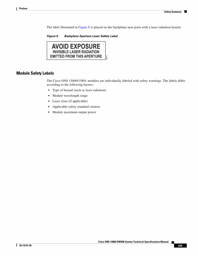
The label illustrated in Figure 9 is placed on the backplane near ports with a laser radiation hazard.
Figure 9 Backplane Aperture Laser Safety Label
Module Safety Labels
The Cisco ONS 15800/15801 modules are individually labeled with safety warnings. The labels differ according to the following factors:
• Type of hazard (such as laser radiation)
• Module wavelength range
• Laser class (if applicable)
• Applicable safety standard citation
• Module maximum output power
6427
7
AVOID EXPOSUREINVISIBLE LASER RADIATION
EMITTED FROM THIS APERTURE

xxCisco ONS 15800 DWDM System Technical Specifications Manual
78-13141-03
PrefaceConventions
ConventionsThis publication uses the following conventions:
Warning Means danger. The user is in a situation that could cause bodily injury. Before working on any equipment, be aware of the hazards involved with electrical circuitry and optical lasers and be familiar with standard practices for preventing accidents.
Caution Means reader be careful. In this situation, the user might do something that could result in equipment damage or loss of data.
Note Means reader take note. Notes contain helpful suggestions or references to material not covered in the manual.
Convention Application
boldface Commands and keywords.
italic Command input that is supplied by the user.
[ ] Keywords or arguments that appear within square brackets are optional.
{ x | x | x } A choice of keywords (represented by x) appears in braces separated by vertical bars. The user must select one.
Ctrl The control key. For example, where hold down the Control key while pressing the D key. Ctrl + D is written.
screen font Examples of information displayed on the screen.
boldface screen font Examples of information that the user must enter.
< > Command parameters that must be replaced by module-specific codes.

xxiCisco ONS 15800 DWDM System Technical Specifications Manual
78-13141-03
PrefaceDocumentation InfoSet Structure
Documentation InfoSet StructureCisco Optical Networking System 15800 and 15801 Series DWDM Documentation InfoSet contains the following manual types:
• System Descriptions—Provides an overview of operation, engineering, administration, maintenance, performance, system-level technical specifications, supervision tools, and craft terminal software associated with the system.
• System Technical Specifications—Summarizes system-level and module-level technical specifications, including supervision, analog and digital alarm threshold settings, engineering specifications, and system performance.
• Common Platform Installation Manuals—Provides procedures for installing and configuring components common to all systems. Also includes safety, unpacking and storage, equipment and site verification, power and grounding, and post-installation procedures.
• Installation, Setup, and Test Manuals—Provides procedures for installing, setting up, and testing standard hardware and software components within a system. Also includes safety, unpacking and storage, equipment and site verification, power and grounding, and post-installation procedures.
• System Configuration Manuals—Descriptions and detailed illustrations of standard system configurations.
• Module Handbooks—Each handbook provides functional descriptions, technical specifications, and system relationship information for a single hardware module. Each handbook also provides installation, removal, and configuration procedures associated with the module.
• Message Manual—Provides a reference guide for software commands and responses between software and firmware during setup, polling, and reporting on the system.
• Software Installation Manuals—Each manual provides installation and removal information for a specific software application.
• Software Administrator Manuals—Each manual describes the operation, security implementation, and management of a software product at a system administrator access level.

xxiiCisco ONS 15800 DWDM System Technical Specifications Manual
78-13141-03
PrefaceObtaining Documentation
Obtaining DocumentationThe following sections provide sources for obtaining documentation from Cisco Systems.
World Wide WebYou can access the most current Cisco documentation on the World Wide Web at the following sites:
• http://www.cisco.com
• http://www-china.cisco.com
• http://www-europe.cisco.com
Ordering DocumentationCisco Optical Networking System documentation is available in a CD-ROM package that is available in the following ways:
• Registered Cisco Direct Customers can order Cisco Product documentation from the Networking Products MarketPlace:
http://www.cisco.com/cgi-bin/order/order_root.pl
• Registered Cisco.com users can order the Documentation CD-ROM through the online Subscription Store:
http://www.cisco.com/go/subscription
• Nonregistered Cisco.com users can order documentation through a local account representative by calling Cisco corporate headquarters (California, USA) at 408 526-7208 or, in North America, by calling 800 553-NETS(6387).
Documentation FeedbackIf you are reading Cisco product documentation on the World Wide Web, you can submit technical comments electronically. Click Feedback in the toolbar and select Documentation. After you complete the form, click Submit to send it to Cisco.
You can e-mail your comments to [email protected].
We appreciate your comments.

xxiiiCisco ONS 15800 DWDM System Technical Specifications Manual
78-13141-03
PrefaceObtaining Technical Assistance
Obtaining Technical AssistanceCisco provides Cisco.com as a starting point for all technical assistance. Customers and partners can obtain documentation, troubleshooting tips, and sample configurations from online tools. For Cisco.com registered users, additional troubleshooting tools are available from the TAC website.
Cisco.comCisco.com is the foundation of a suite of interactive, networked services that provides immediate, open access to Cisco information and resources at anytime, from anywhere in the world. This highly integrated Internet application is a powerful, easy-to-use tool for doing business with Cisco.
Cisco.com provides a broad range of features and services to help customers and partners streamline business processes and improve productivity. Through Cisco.com, you can find information about Cisco and our networking solutions, services, and programs. In addition, you can resolve technical issues with online technical support, download and test software packages, and order Cisco learning materials and merchandise. Valuable online skill assessment, training, and certification programs are also available.
Customers and partners can self-register on Cisco.com to obtain additional personalized information and services. Registered users can order products, check on the status of an order, access technical support, and view benefits specific to their relationships with Cisco.
To access Cisco.com, go to the following website:
http://www.cisco.com
To register for Cisco.com, go to the following website:
http://www.cisco.com/register/
Technical Assistance CenterThe Cisco Technical assistance Center (TAC) website is available to all customers who need technical assistance with a Cisco product or technology that is under warranty or covered by a maintenance contract.
Technical assistance and customer service for Cisco ONG products are available from these sources:
• Optical Networking Group (ONG) TAC in the United States: 1-877-323-7368
• Europe, Middle East, and Asia (EMEA) ONG TAC: +32 2704 5601
• Customer Service in the United States and Canada: 1-800-553-NETS (1-800-553-6387)
• Customer Service in all other countries: 1-408-526-7208
• Customer Service global e-mail: [email protected]

xxivCisco ONS 15800 DWDM System Technical Specifications Manual
78-13141-03
PrefaceObtaining Technical Assistance
Contacting TAC by Telephone
If you have a priority level 1 (P1) or priority level 2 (P2) problem, contact TAC by telephone and immediately open a case.
P1 and P2 level problems are defined as follows:
• P1—Production network is down, causing a critical impact to business operations if service is not restored quickly. No workaround is available.
• P2—Production network is severely degraded, affecting significant aspects of business operations. No workaround is available.
Contacting TAC Using the Cisco TAC Website
Use the Cisco TAC website to find answers to priority level 3 (P3) or priority level 4 (P4) problems:
http://www.cisco.com/tac
P3 and P4 level problems are defined as follows:
• P3—Network performance is degraded. Network functionality is noticeably impaired, but most business operations continue.
• P4—Information or assistance about Cisco product capabilities, product installation, or basic product configuration is needed.
If the technical issue cannot be resolved by using the TAC online resources, Cisco.com registered users can open a case online by using the TAC Case Open tool at the following website:
http://www.cisco.com/tac/caseopen
C H A P T E R
1-1Cisco ONS 15800 DWDM System Technical Specifications Manual
78-13141-03
1Introduction
This chapter contains information about the structure and standards for the Cisco ONS 15800 DWDM System Technical Specifications Manual.
Purpose of This PublicationThis manual is used to design networks containing the ONS 15800 dense wavelength division multiplexing (DWDM) system. It is used during the design, test, validation, and verification phases.
Manual StructureThe manual is organized into five chapters:
• Chapter 1, “Introduction,” introduces the manual, shows its structure, lists applicable standards, and specifies revision history.
• Chapter 2, “System Performance,” contains information about the ONS 15800 system operation and capabilities.
• Chapter 3, “Module Specifications.” contains optical, electrical, and mechanical module specifications.
• Chapter 4, “Supervision and Alarms,” contains supervision information and module alarm data.
• Chapter 5, “Engineering Specifications,” contains physical layout, system environmental and reliability data, and electrical specifications.
ReferencesONS 15800 system design, construction, and performance adhere to the standards in the section “Applicable Standards”. Other ONS 15800 system references are listed in the section “Additional ONS 15800 System Information”. Standards related to wavelength division multiplexing, but not cited in this manual, are listed in the section “Related Standards About Wavelength Division Multiplexing”.
Applicable StandardsThis manual contains references to the following standards:

1-2Cisco ONS 15800 DWDM System Technical Specifications Manual
78-13141-03
Chapter 1 IntroductionReferences
• 21 CFR 1040.10
• ANSI T1.1-5.03-1994
• British Telecom HRD4
• British Telecom HRD5
• CISPR 22 (paragraph 4)
• EIA/TIA-232
• EIA/TIA-422
• EIA/TIA-485
• FCC Part 15
• IEC 60825-2
• IEEE 8802.3
• ITU-T G.652
• ITU-T G.653
• ITU-T G.655
• ITU-T G.692
• ITU-T G.704
• ITU-T G.706
• ITU-T G.784
• ITU-T G.826
• ITU-T G.957
• ITU-T V.11
• ITU-T X.21
• NF-EN 55022 (paragraph 3)
• Telcordia GR-63-CORE (sections 4.1–4.7)
• Telcordia GR-1089-CORE (sections 2, 3, 4, 7, and 9)
• Telcordia GR-253-CORE
• Telcordia TR NWT-001089
• UL 1950
Additional ONS 15800 System InformationThe following manuals and standards provide more information about the ONS 15800 system:
• Cisco ONS 15800 DWDM System Description Manual
• Cisco ONS 15800 DWDM System Installation, Setup, and Test Manual
• Cisco ONS 15800 module handbooks (for each ONS 15800 system module)
• Cisco Photonics Local Terminal Software Administrator Manual for the ONS 15800/15801 System
• TL1 Software Message Manual for the Cisco ONS 15800/15801 System
1-3Cisco ONS 15800 DWDM System Technical Specifications Manual
78-13141-03
Chapter 1 IntroductionReferences
Related Standards About Wavelength Division MultiplexingThe following standards relate to DWDM and the ONS 15800 system, but are not directly cited in this manual:
• ANSI T1.119 1994
• ANSI T1.119.01 1995
• ANSI T1.204 1993
• ANSI T1.208 1993
• ANSI T1.210 1993
• ANSI T1.214b 1995
• ANSI T1.215 1994
• ANSI T1.224 1992
• ANSI T1.227 1995
• ANSI T1.229 1992
• ANSI T1.229a 1995
• ANSI T1.233 1993
• ANSI T1.240 1996
• ANSI T1.243 1995
• ANSI T1.245 1995
• ANSI T1.247 1995
• ANSI T1.252 1996
• ANSI T1.254 1997
• IEC 1291-1
• IEC 1291-4
• ITU-T G.661
• ITU-T G.662
• ITU-T G.663
• ITU-T G.664
• ITU-T G.671
• ITU-T G.681
• ITU-T G.691
• ITU-T G.958
• ITU-T M. 2120
• ITU-T M.3010
• ITU-T M.3100
• ITU-T Q.811
• ITU-T Q.812
• ITU-T Q.821

1-4Cisco ONS 15800 DWDM System Technical Specifications Manual
78-13141-03
Chapter 1 IntroductionRevision History
• ITU-T Q.822
• ITU-T X.700
• ITU-T X.721
• ITU-T X.735
• ITU-T-SG13-Opt-Arch
• ITU-T-SG15-OFA-WDM
• ITU-T-SG4-TMN
• Telcordia GR-1312-CORE
• Telcordia GR-2918-CORE
• Telcordia GR-499-CORE
• Telcordia GR-831-CORE
• Telcordia GR-833-CORE
Revision History
(Re)Issue or Rev Description Date Reason
01 February 2002 Original Issue

C H A P T E R
2-1Cisco ONS 15800 DWDM System Technical Specifications Manual
78-13141-03
2System Performance
This chapter presents the general system performance specifications for the ONS 15800 dense wavelength division multiplexing (DWDM) system.
Performance CharacteristicsThis section covers the general performance characteristics of the ONS 15800 system, including the band separation principle, channel allocations, and configurations.
Band Separation PrincipleONS 15800 system channel population typically begins with the 24 red-band channels and then utilizes the 8 blue-band channels. The various channels are spaced 100 GHz apart and can carry traffic at a single line speed (2.5 Gbps or 10 Gbps). A total of 32 channels can carry traffic on a single fiber pair.
The ONS 15800 system is based on transmission band separation. Channels are grouped as bands according to their wavelength in the 1550-nm transmission window. The lower wavelengths from 1529 nm to 1535 nm are called the blue band. The middle wavelengths from 1542 nm to 1561 nm are called the red band. The upper wavelengths are the infrared band. (Figure 2-1).
Figure 2-1 Transmission Window Bands
Band-specific multiplexers and demultiplexers are used in the system to give greater modularity and scalability. The bands are amplified separately to narrow and flatten each region, so equalization and tilt effects are greatly reduced. The results make the best use of the optical amplifier spectrum characteristics.
Channel Allocations and Span BudgetsThe ONS 15800 system model allocates and numbers channels spaced at 100-GHz intervals. Blue-band channel allocations are listed in Table 2-1. Red-band channel allocations are listed in Table 2-2.
Blue band Red band Infrared band
1530 nm 1540 nm 1550 nm 1560 nm 1570 nm 1580 nm 1590 nm 1600 nm
6492
2
2-2Cisco ONS 15800 DWDM System Technical Specifications Manual
78-13141-03
Chapter 2 System PerformancePerformance Characteristics
Blue-Band Channel Allocation
The ONS 15800 system can contain up to 8 blue-band channels (Table 2-1). These are designated as channels 01 to 08.
Red-Band Channel Allocation
The ONS 15800 system can contain up to 24 red-band channels (Table 2-2). These are designated as channels 09 to 32.
Table 2-1 Allocation of Blue Band Channels
Channel Number Nominal (THz) Channel (nm)
01 196.0 1529.55
02 195.9 1530.33
03 195.8 1531.12
04 195.7 1531.90
05 195.6 1532.68
06 195.5 1533.47
07 195.4 1534.25
08 195.3 1535.04
Table 2-2 Allocation of Red Band Channels
Channel Number Nominal (THz) Channel (nm)
09 194.4 1542.14
10 194.3 1542.94
11 194.2 1543.73
12 194.1 1544.53
13 194.0 1545.32
14 193.9 1546.12
15 193.8 1546.92
16 193.7 1547.72
17 193.6 1548.51
18 193.5 1549.32
19 193.4 1550.12
20 193.3 1550.92
21 193.2 1551.72
22 193.1 1552.52
23 193.0 1553.33
24 192.9 1554.13
25 192.8 1554.94
26 192.7 1555.75
2-3Cisco ONS 15800 DWDM System Technical Specifications Manual
78-13141-03
Chapter 2 System PerformanceSpan Budgets
Span BudgetsThe ONS 15800 system can be configured to carry 2.5-Gbps traffic, 10-Gbps traffic, or both speeds simultaneously. The channel count at each speed varies by fiber type. This section addresses channel counts and span budgets for 2.5-Gbps operations, then addresses those for 10-Gbps operations.
Note Minimum span loss is 14 dB without forward error correction (FEC) and with in-band FEC (IB-FEC). With out-of-band FEC (OOB-FEC) minimum span loss is 17 dB.
Note Receive Transponder modules can be placed between the ONS 15800 system equipment and the synchronous optical network/synchronous digital hierarchy (SONET/SDH) equipment, or between the ONS 15800 system equipment and the Internet protocol (IP) or asynchronous transfer mode (ATM) equipment. The Receive Transponder modules retime, reshape, and regenerate the signal into a fully compliant SONET short-reach/SDH intraoffice interface.
Channel Counts and Span Budgets for 2.5-Gbps OperationThe span budgets for 2.5-Gbps operation are defined for end-of-life (EOL) conditions. They are based on the following reference points indicated in ITU-T G.692:
• Main path interface at the receiver (MPI-R)
• Main path interface at the transmitter (MPI-S)
• Reference point on the optical fiber just before the input optical connector (R')
• Reference point just after the line output optical connector (S’)
Table 2-4 shows the channel counts and maximum span budgets by fiber type for 2.5-Gbps operation without forward error correction (FEC). Table 2-5 shows the channel counts and maximum span budgets by fiber type for 2.5-Gbps operation with out-of-band forward error correction (OOB-FEC). The values are also valid with optical line terminal equipment (OLTE), in compliance with ITU-T G.957 recommendations. The table indicates whether Receive Transponder (RXT) modules are needed to retime, reshape, and regenerate the signals.
27 192.6 1556.55
28 192.5 1557.36
29 192.4 1558.17
30 192.3 1558.98
31 192.2 1559.79
32 192.1 1560.61
Table 2-2 Allocation of Red Band Channels (continued)
Channel Number Nominal (THz) Channel (nm)

2-4Cisco ONS 15800 DWDM System Technical Specifications Manual
78-13141-03
Chapter 2 System PerformanceSpan Budgets
Table 2-3 TChannel Counts and Section Span Budgets by Fiber Type for 2.5-Gbps Operation without FEC
Fiber Channel Count and Allocation RXT1
Used
1. Receive Transponder (RXT) modules
Spans Unit
1 2 3 4 5 6 7
SMF2
2. ITU-T G.652
83
3. Rows with 8 and 16 channels are intended for systems that will not be upgraded to use more channels.
Red band: all channels 09 to 16 Yes 374
4. The span budget is limited by the optical service channel (OSC) power budget and is guaranteed after verifying fiber attenuation at 1480 nm.
34 32 31 30 29 27 dB
26 Blue band: channels 01, 04 to 08Red band: channels 09 to 12 and channels 17 to 32
35 32 30 29 28 27 25 dB
32 Blue band: all channels 01 to 08Red band: all channels 09 to 32
32 29 27 26 25 24 22 dB
SMF2, 5
5. The span budgets are subject to interoperability testing with OLTE.
20 Blue band: channels 01, 06 to 08Red band: channels 09 to 12and channels 21 to 32
No 35 32 30 29 28 27 25 dB
26 Blue band: channels 01, 04 to 08Red band: channels 09 to 12and channels 17 to 32
32 29 27 26 25 24 22 dB
32 Blue band: all channels 01 to 08Red band: all channels 09 to 32
29 26 24 23 22 21 19 dB
DS6, 7
6. ITU-T G.653
7. The particular channels used with this fiber do not affect allocation or span budget.
12 Blue band: 4 channelsRed band: 8 channels
N/A 32 29 27 26 25 24 23 dB
LS8, 7
8. ITU-T G.655
22 Blue band: 8 channelsRed band: 14 channels
Yes 32 29 27 26 25 24 23 dB
32 Blue band: 8 channelsRed band: 24 channels
29 26 24 23 22 21 20 dB
TWF7, 8, 9
9. TWF = TrueWave fiber (TWC = TrueWave classic, TW+ = TrueWave +, and TW-RS = TrueWave reduced slope)
28 Blue band: 4 channelsRed band: 24 channels
Yes 32 29 27 26 25 24 23 dB
TWF8, 7, 9 24 Blue band: 4 channelsRed band: 20 channels
No 32 29 27 26 25 24 23 dB
28 Blue band: 4 channelsRed band: 24 channels
29 26 24 23 22 21 20 dB
E-LEAF8 32 Blue band: 8 channelsRed band: 24 channels
Yes 32 29 27 26 25 24 23 dB
E-LEAF8, 10
10. E-LEAF = large effective area fiber
26 Blue band: 6 channelsRed band: 20 channels
No 32 29 27 26 25 24 23 dB
32 Blue band: 8 channelsRed band: 24 channels
29 26 24 23 22 21 20 dB

2-5Cisco ONS 15800 DWDM System Technical Specifications Manual
78-13141-03
Chapter 2 System PerformanceSpan Budgets
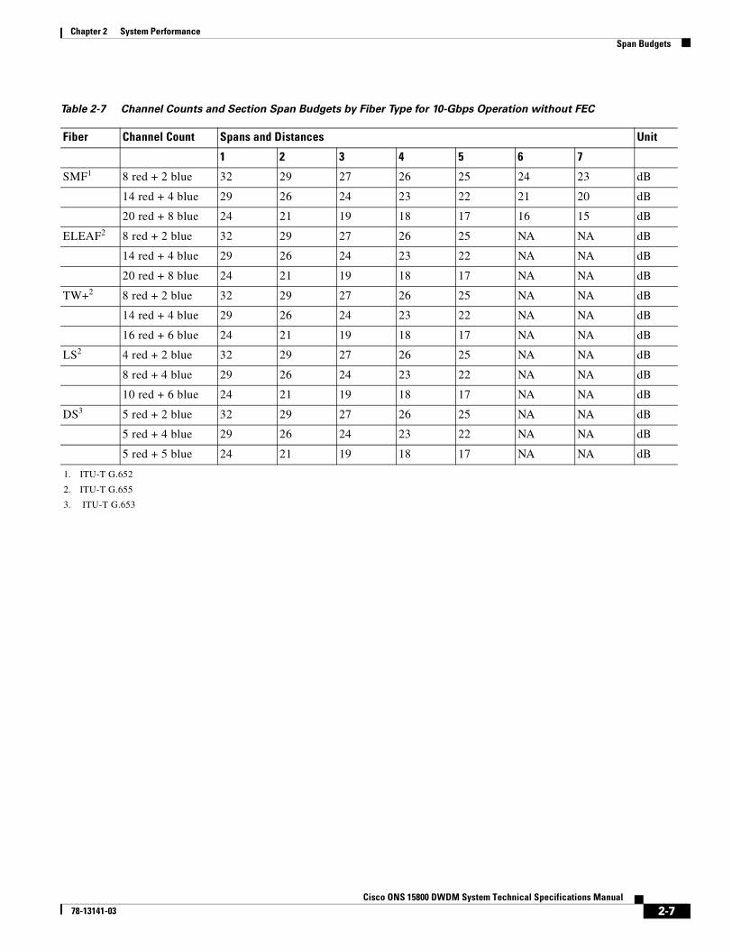
Channel Counts and Span Budgets for 10-Gbps OperationTable 2-5 shows the channel counts and maximum span budgets for 10-Gbps operation with In-Band Forward Error Correction (IB FEC). Table 2-6 shows the channel counts and maximum span budgets for 10-Gbps operation with OB FEC. Table 2-7 shows the channel counts and maximum span budgets for 10-Gbps operation without FEC. Span budgets (without OB FEC) factor in the use of Receive Transponder–10 Gbps–B1 Monitoring (RXT-10G-M) modules to retime, reshape, and regenerate signals.
Table 2-4 Channel Counts and Section Span Budgets by Fiber Type for 2.5-Gbps Operation with OB FEC
Fiber Channel Count and Allocation Spans and Distances Unit
1 2 3 4 5 6 7 8 9 10
SMF1
1. TU-T G.652
32 Blue band: 8 channelsRed band: 24 channels
38 352
2. Maximum span should be limited to 33 dB by the LSM (Line Service Modem).
33 323
3. Maximum span should be limited to 30 dB by the LSM.
313 30 29 28 27 26 dB
E-LEAF4
4. ITU-T G.655
32 Blue band: 8 channelsRed band: 24 channels
38 352 33 323 313 30 29 28 27 26 dB
TW-RS2 32 Blue band: 8 channelsRed band: 24 channels
37 342 32 313 30 29 28 27 26 25 dB
Teralight 32 Blue band: 8 channelsRed band: 24 channels
37 342 32 313 30 29 28 27 26 25 dB
DS5
5. ITU-T G.653
10 Blue band: 5 channelsRed band: 5 channels
37 342 32 313 30 28 26 25 NA NA dB
Table 2-5 Channel Counts and Section Span Budgets by Fiber Type for 10-Gbps Operation with IB FEC
Fiber Channel Count Spans and Distances Unit
1 2 3 4 5 6 7
SMF1 12 red + 4 blue2 32 29 27 26 25 24 23 dB
16 red + 6 blue4 29 26 24 23 22 21 20 dB
24 red + 8 blue 24 21 19 18 17 16 15 dB
ELEAF3 12 red + 4 blue 32 29 27 26 25 NA NA dB
16 red + 6 blue 29 26 24 23 22 NA NA dB
24 red + 8 blue 24 21 19 18 17 NA NA dB
TWC3 9 red + 4 blue 32 29 27 26 25 NA NA dB
14 red + 4 blue 29 26 24 23 22 NA NA dB
16 red + 4 blue 24 21 19 18 17 NA NA dB
TW+3 12 red + 4 blue 32 29 27 26 25 NA NA dB
16 red + 6 blue 29 26 24 23 22 NA NA dB

2-6Cisco ONS 15800 DWDM System Technical Specifications Manual
78-13141-03
Chapter 2 System PerformanceSpan Budgets
TW-RS3 12 red + 4 blue 32 29 27 26 25 NA NA dB
16 red + 6 blue 29 26 24 23 22 NA NA dB
24 red + 8 blue 24 21 19 18 17 NA NA dB
LS3 6 red + 4 blue 32 29 27 26 25 NA NA dB
10 red + 6 blue 29 26 24 23 22 NA NA dB
12 red + 8 blue 24 21 19 18 17 NA NA dB
DS4 8 red + 4 blue 32 29 27 26 25 NA NA dB
1. ITU-T G.652
2. For span lengths greater than 65 Km the blue band has the following limitations: – maximum of 4 channels for the 5 x 22 dB family budget– maximum of 2 channels for the 5 x 25 dB family budget
3. ITU-T G.655
4. ITU-T G.653
Table 2-6 Channel Counts and Section Span Budgets by Fiber Type for 10-Gbps Operation with OB FEC
Fiber Channel Count and Allocation Spans and Distances Unit
1 2 3 4 5 6 7 8 9 10
SMF1
1. ITU-T G.652
32 Blue band: 8 channelsRed band: 24 channels
32 30 28 27 26 25 24 23 22 21 dB
E-LEAF2
2. ITU-T G.655
32 Blue band: 8 channelsRed band: 24 channels
35 32 31 30 29 28 26 24 NA NA dB
TW-RS2 32 Blue band: 8 channelsRed band: 24 channels
35 32 31 30 29 28 26 25 22 21 dB
Teralight 32 Blue band: 8 channelsRed band: 24 channels
35 32 31 30 29 28 26 25 24 23 dB
TWC2 30 Blue band: 6 channelsRed band: 24 channels
33 29 27 26 25 NA NA NA NA NA dB
TW+2 32 Blue band: 8 channelsRed band: 24 channels
34 31 29 28 27 NA NA NA NA NA dB
LS2 32 Blue band: 8 channelsRed band: 24 channels
28 25 23 22 21 NA NA NA NA NA dB
28 Blue band: 8 channelsRed band: 20 channels
34 30 28 26 25 NA NA NA NA NA dB
DS3
3. ITU-T G.653
10 Blue band: 5 channelsRed band: 5 channels
35 32 30 28 27 NA NA NA NA NA dB
Table 2-5 Channel Counts and Section Span Budgets by Fiber Type for 10-Gbps Operation with IB FEC
2-7Cisco ONS 15800 DWDM System Technical Specifications Manual
78-13141-03
Chapter 2 System PerformanceSpan Budgets
Table 2-7 Channel Counts and Section Span Budgets by Fiber Type for 10-Gbps Operation without FEC
Fiber Channel Count Spans and Distances Unit
1 2 3 4 5 6 7
SMF1
1. ITU-T G.652
8 red + 2 blue 32 29 27 26 25 24 23 dB
14 red + 4 blue 29 26 24 23 22 21 20 dB
20 red + 8 blue 24 21 19 18 17 16 15 dB
ELEAF2
2. ITU-T G.655
8 red + 2 blue 32 29 27 26 25 NA NA dB
14 red + 4 blue 29 26 24 23 22 NA NA dB
20 red + 8 blue 24 21 19 18 17 NA NA dB
TW+2 8 red + 2 blue 32 29 27 26 25 NA NA dB
14 red + 4 blue 29 26 24 23 22 NA NA dB
16 red + 6 blue 24 21 19 18 17 NA NA dB
LS2 4 red + 2 blue 32 29 27 26 25 NA NA dB
8 red + 4 blue 29 26 24 23 22 NA NA dB
10 red + 6 blue 24 21 19 18 17 NA NA dB
DS3
3. ITU-T G.653
5 red + 2 blue 32 29 27 26 25 NA NA dB
5 red + 4 blue 29 26 24 23 22 NA NA dB
5 red + 5 blue 24 21 19 18 17 NA NA dB

2-8Cisco ONS 15800 DWDM System Technical Specifications Manual
78-13141-03
Chapter 2 System PerformanceSpan Budgets

C H A P T E R
3-1Cisco ONS 15800 DWDM System Technical Specifications Manual
78-13141-03
3Module Specifications
The ONS 15800 system uses four site types. Each site uses specific types of modules:
• Terminal sites—These sites transmit and receive signals. They contain a transmit section (wavelength converters, multiplexers, and transmit power amplifiers) and a receive section (pre-line amplifiers, booster amplifiers, demultiplexers, and optional receive transponders).
• Optical line amplification sites—These sites amplify signals in two stages through pre-line amplifiers and booster optical amplifiers.
• Optical add/drop multiplexing sites—These sites can perform red-band or blue-band full add/drop demultiplexing, or partial add/drop demultiplexing only in the red band.
• Regeneration sites—These sites use transponder modules to retime, reshape, and regenerate (3R) the signal along the line if the overall transmission exceeds the limit given by the span attenuation or dispersion budgets.
The sites are described in the Cisco ONS 15800 DWDM System Description Manual.
Each ONS 15800 site is composed of racks of optical subracks that hold these modules:
• Optical Subracks–Dispersion Compensating Unit (OSR-DCU) for Dispersion Compensating Unit modules
• Optical Subracks–Multiplexer (OSR-MUX) for multiplexer modules
• Optical Subracks (OSR-W) for all other modules.
The modules in each subrack are specific to the site function and configuration.
ONS 15800 modules can be active-optical, passive-optical, or they can have other system functions. Active modules perform an active function to the signal—such as amplifying or shaping—and are powered from the subrack. Passive modules do not perform an active function to the signal and do not receive power from the subrack. Other modules perform power, supervision, or communication functions.
Active ModulesThe ONS 15800 system active modules function as transponders, amplifiers, add/drop multiplexers, or demultiplexers. They have power supplied from the backplane. Transponders operate primarily according to the laser source temperature. Optical amplifiers operate primarily according to pump laser temperature. Demultiplexers and optical add/drop multiplexers operate according to temperature. The classifications, operating parameters, and modules in the active-optical category are shown in Table 3-1.

3-2Cisco ONS 15800 DWDM System Technical Specifications Manual
78-13141-03
Chapter 3 Module SpecificationsActive Modules
Table 3-1 Active Optical Module Operating Parameters
Type Operating Parameters ModuleWhere Shown
Transponders Input modulation, present or absentOutput modulation, present or absentInput power levelOutput power levelLaser source temperatureLaser source bias currentLaser source power
Line Extender Module–Externally Modulated–B1 Monitoring (LEM-EM-Mxx)
Table 3-2
Line Extender Module–Externally Modulated–Forward Error Correction (LEM-EM-Fxx)
Table 3-5
Line Extender Module–10 Gbps–B1 Monitoring (LEM-10G-Mxx)
Table 3-8
Line Extender Module–10 Gbps High output power–B1 Monitoring (LEM-10H-Mxx)
Table 3-10
Line Extender Module–10 Gbps–Forward Error Correction (LEM-10G-Fxx)
Table 3-14
Receive Transponder–Directly Modulated–B1 Monitoring (RXT-DM-M) module
Table 3-17
Receive Transponder–Directly Modulated– Forward Error Correction (RXT-DM-F) module
Table 3-20
Receive Transponder–10 Gbps–B1 Monitoring (RXT-10G-M) module
Table 3-23
Receive Transponder–10 Gbps–Forward Error Correction (RXT-10G-Fxx) module
Table 3-26
Wavelength Converter Module–Externally Modulated–B1 Monitoring (WCM-EM-Mxx)
Table 3-29
Wavelength Converter Module–Externally Modulated–Forward Error Correction (WCM-EM-Fxx)
Table 3-32
Wavelength Converter Module–10 Gbps–B1 Monitoring (WCM-10G-Mxx)
Table 3-35
Wavelength Converter Module–10 Gbps High output power–B1 Monitoring (WCM-10H-Mxx)
Table 3-38
Wavelength Converter Module–10 Gbps–Forward Error Correction (WCM-10G-Fxx)
Table 3-41
Optical amplifiers Input power levelOutput power levelPump laser temperaturePump laser bias currentPump laser power
Add Drop Amplifier (ADA) module Table 3-44
Blue-band Booster Amplifier (BBA) module Table 3-47
Blue-band Booster Amplifier–10 Gbps (BBA-10G) module Table 3-50
Pre-Line Amplifier (PRE-L) module Table 3-53
Red-band Booster Amplifier (RBA) module Table 3-56
Red-band Booster Amplifier–10 Gbps (RBA-10G) module Table 3-59
Transmit Power Amplifier–Blue band (TPA-B) module Table 3-62
Transmit Power Amplifier–Red band (TPA-R) module Table 3-65
Optical add/drop multiplexer
Temperature Optical Add/Drop Multiplexer (OADM-P4) module Table 3-68

3-3Cisco ONS 15800 DWDM System Technical Specifications Manual
78-13141-03
Chapter 3 Module SpecificationsActive Modules
Line Extender Module–Externally Modulated–B1 MonitoringA Line Extender Module–Externally Modulated–B1 Monitoring (LEM-EM-Mxx) is used to pass channels through 2.5-Gbps partial or full optical add/drop multiplexing sites and to extend transmission distances in 2.5-Gbps regeneration sites. LEM-EM-Mxx modules can be used to cascade up to 15 links when overall distance exceeds span attenuation or dispersion budget limits. LEM-EM-Mxx modules are located in the Optical Subrack (OSR-W). Optical characteristics of the LEM-EM-Mxx module are shown in Table 3-2. Electrical characteristics are shown in Table 3-3. Mechanical characteristics are shown in Table 3-4.
Demultiplexers Temperature 8-channel Wavelength Demultiplexer–Blue band (8WD-B) module
Table 3-71
24-channel Wavelength Demultiplexer–Red band (24WD-R) module
Table 3-74
24-channel Wavelength Demultiplexer–Low Loss–Red band (24WD-LLR) module
Table 3-77
Table 3-1 Active Optical Module Operating Parameters (continued)
Type Operating Parameters ModuleWhere Shown
Table 3-2 LEM-EM-Mxx Module Optical Characteristics
Item Condition Min. Max. Unit
Optical Input Parameters
Receiver input sensitivity BER1 ≤ 10–13
OSNR2 = 13.5 dB at 0.5 nm resolution bandwidthSpecified temperature range
–25 –10 dBm
Maximum input optical power Maximum rating — –7 dBm
Optical Output Parameters
Output power — –0.5 +0.5 dBm
Output power at monitoring port — –15 –11 dBm
Optical return loss Front-panel SC connectors 28 — dB
Optical return loss Backplane E-2000 connector 40 — dB
Jitter Characteristics
Jitter transfer or tolerance ITU-T3 G.958 (ANSI4 T1.105.03-1994) Comply — —1BER = bit error rate2OSNR = optical signal to noise ratio3ITU-T = International Telecommunication Union4ANSI = American National Standards Institute

3-4Cisco ONS 15800 DWDM System Technical Specifications Manual
78-13141-03
Chapter 3 Module SpecificationsActive Modules
Line Extender Module–Externally Modulated–Forward Error CorrectionA Line Extender Module–Externally Modulated–Forward Error Correction (LEM-EM-Fxx) is used at regeneration sites. The module provides forward error correction (FEC) decoding for error correction, performance monitoring, and FEC encoding capabilities. LEM-EM-Fxx modules are located in the Optical Subrack (OSR-W). Optical characteristics of the LEM-EM-Fxx module are shown in Table 3-5. Electrical characteristics are shown in Table 3-6. Mechanical characteristics are shown in Table 3-7.
Table 3-3 LEM-EM-Mxx Module Electrical Characteristics
Item Characteristics
Power consumption 22 W maximum
Input voltage –48 VDC
Table 3-4 LEM-EM-Mxx Module Mechanical Characteristics
Item Characteristics
Height 403.00 mm (15.87 in.)
Width 30.45 mm (1.20 in.)
Depth 220.00 mm (8.66 in.)
Weight 1.60 kg (3.53 lb)
Table 3-5 LEM-EM-Fxx Module Optical Characteristics
Item Condition Min. Max. Unit
Optical Input Parameters
Input wavelength range — 1520 1605 nm
Receiver input sensitivity BER ≤ 10-13
OSNR = ≥ 8.5 dB at 0.2 nm resolution bandwidthSpecified temperature range
–25 –10 dBm
Maximum input optical power Maximum rating 0 dBm
Optical return loss — 30 — dB
Optical Output Parameters
Output power 25°C (77°F) –5 +2 dBm
Optical return loss 25°C (77°F) 40 — dB
Jitter Characteristics
Jitter transfer ITU-T GR.253 (ANSI T1.105.03-1994) Comply — —

3-5Cisco ONS 15800 DWDM System Technical Specifications Manual
78-13141-03
Chapter 3 Module SpecificationsActive Modules
Line Extender Module–10 Gbps–B1 MonitoringA Line Extender Module–10 Gbps–B1 Monitoring (LEM-10G-Mxx) is used at 10-Gbps regeneration sites. It is a retime, reshape, and regenerate (3R) signal regenerator used to extend the maximum length of a link. LEM-10G-Mxx modules are located in the OSR-W subrack. Optical characteristics of the module are shown in Table 3-8. Electrical characteristics are shown in Table 3-9. Mechanical characteristics are shown in Table 3-10.
Table 3-6 LEM-EM-Fxx Module Electrical Characteristics
Item Characteristics
Power consumption 25 W maximum, 22 W typical
Input voltage –48 VDC
Table 3-7 LEM-EM-Fxx Module Mechanical Characteristics
Item Characteristics
Height 403.00 mm (15.87 in.)
Width 30.45 mm (1.20 in.)
Depth 220.00 mm (8.66 in.)
Weight 1.60 kg (3.53 lb)
Table 3-8 LEM-10G-Mxx Module Optical Characteristics
Item Condition Min. Max. Unit
Optical Input Parameters
Receiver input sensitivity BER ≤ 10-13
ONSR = 16 dB at 0.5 nm resolution bandwidth Negligible PMD1; NRZ2 input formatT = 25°C
–11 –1 dBm
BER ≤ 10-11
ONSR = 15 dB at 0.5 nm resolution bandwidth Negligible PMD1; NRZ input formatT = 25°C
–11 –1 dBm
Maximum input optical power Maximum rating — +10 dBm
Accepted input bit rate NRZ2 9.95328 — Gbps
Optical Output Parameters
Output optical power, OUT3 25°C (77°F) –0.5 +0.5 dBm
Output optical power, OUT 0–50°C (32–122°F) –1.5 +1.5 dBm
Output optical power, MON4 25°C (77°F) –13.5 –12.5 dBm
Back-to-back power penalty — — 1 dB
Input optical return loss SC connector 27 — dB
Output optical return loss E-2000 connector — 40 dB

3-6Cisco ONS 15800 DWDM System Technical Specifications Manual
78-13141-03
Chapter 3 Module SpecificationsActive Modules
Line Extender Module–10 Gbps High Output Power–B1 Monitoring ModuleThe Line Extender Module–10 Gbps High output power–B1 Monitoring (LEM-10H-Mxx) is a retime, reshape, and regenerate (3R) signal regenerator used at 10-Gbps regeneration sites to extend the maximum length of a link. The module is located in the OSR-W subrack. Optical characteristics of the module are shown in Table 3-11. Electrical characteristics are shown in Table 3-12. Mechanical characteristics are shown in Table 3-13.
Jitter Characteristics
Jitter peak-to-peak — — 27 ps1PMD = polarization mode dispersion2NRZ = nonreturn to zero3OUT = output port4MON = monitor port
Table 3-9 LEM-10G-Mxx Module Electrical Characteristics
Item Characteristics
Power consumption 45 W maximum
Input voltage –48 VDC
Table 3-10 LEM-10G-Mxx Module Mechanical Characteristics
Item Characteristics
Height 403.00 mm (15.87 in.)
Width 60.90 mm (2.40 in.)
Depth 220.00 mm (8.66 in.)
Weight 2.30 Kg (5.07 lb)
Table 3-8 LEM-10G-Mxx Module Optical Characteristics (continued)
Item Condition Min. Max. Unit
Table 3-11 LEM-10H-Mxx Module Optical Characteristics
Item Conditions Min. Max. Unit
Optical Input Parameters
Receiver input sensitivity BER ≤ 10-13
OSNR = 16 dB at 0.5 nm resolution bandwidthNegligible PMDNRZ input format Over all temperature ranges
–11 –1 dBm
Maximum input optical power Maximum rating — +10 dBm
Accepted input bit rate NRZ 9.95328 — Gbps
3-7Cisco ONS 15800 DWDM System Technical Specifications Manual
78-13141-03
Chapter 3 Module SpecificationsActive Modules
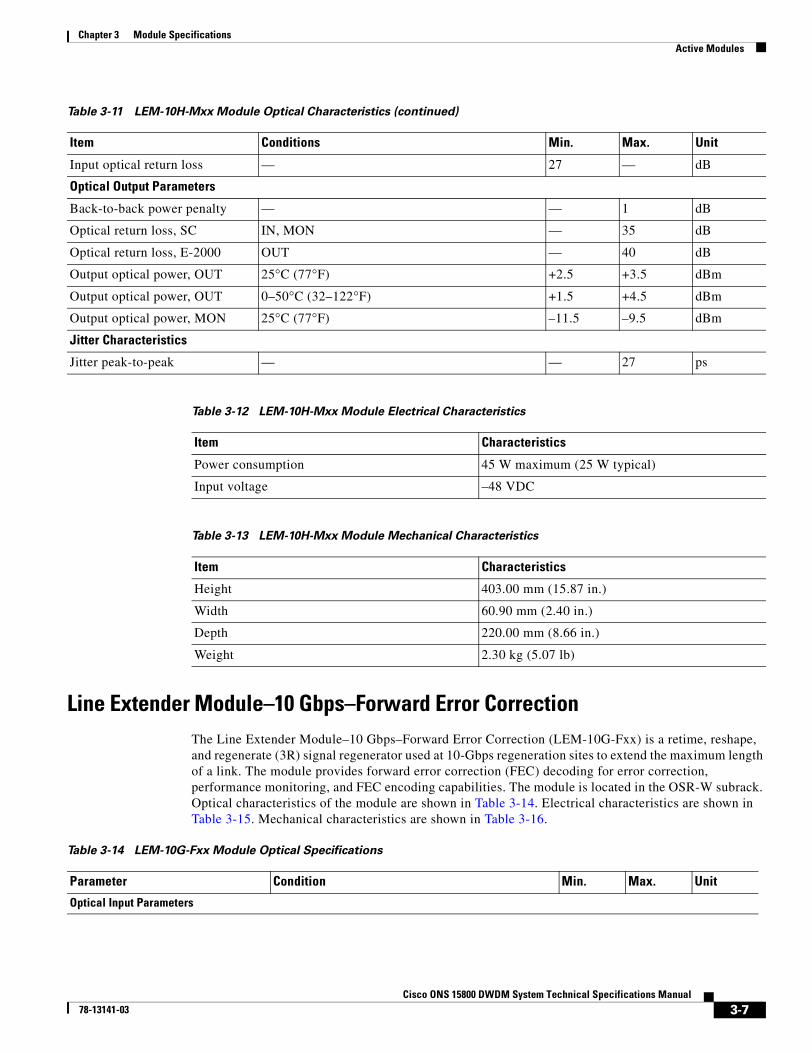
Line Extender Module–10 Gbps–Forward Error CorrectionThe Line Extender Module–10 Gbps–Forward Error Correction (LEM-10G-Fxx) is a retime, reshape, and regenerate (3R) signal regenerator used at 10-Gbps regeneration sites to extend the maximum length of a link. The module provides forward error correction (FEC) decoding for error correction, performance monitoring, and FEC encoding capabilities. The module is located in the OSR-W subrack. Optical characteristics of the module are shown in Table 3-14. Electrical characteristics are shown in Table 3-15. Mechanical characteristics are shown in Table 3-16.
Input optical return loss — 27 — dB
Optical Output Parameters
Back-to-back power penalty — — 1 dB
Optical return loss, SC IN, MON — 35 dB
Optical return loss, E-2000 OUT — 40 dB
Output optical power, OUT 25°C (77°F) +2.5 +3.5 dBm
Output optical power, OUT 0–50°C (32–122°F) +1.5 +4.5 dBm
Output optical power, MON 25°C (77°F) –11.5 –9.5 dBm
Jitter Characteristics
Jitter peak-to-peak — — 27 ps
Table 3-12 LEM-10H-Mxx Module Electrical Characteristics
Item Characteristics
Power consumption 45 W maximum (25 W typical)
Input voltage –48 VDC
Table 3-13 LEM-10H-Mxx Module Mechanical Characteristics
Item Characteristics
Height 403.00 mm (15.87 in.)
Width 60.90 mm (2.40 in.)
Depth 220.00 mm (8.66 in.)
Weight 2.30 kg (5.07 lb)
Table 3-11 LEM-10H-Mxx Module Optical Characteristics (continued)
Item Conditions Min. Max. Unit
Table 3-14 LEM-10G-Fxx Module Optical Specifications
Parameter Condition Min. Max. Unit
Optical Input Parameters

3-8Cisco ONS 15800 DWDM System Technical Specifications Manual
78-13141-03
Chapter 3 Module SpecificationsActive Modules
Receive Transponder–Directly Modulated–B1 Monitoring ModuleThe Receive Transponder–Directly Modulated–B1 Monitoring (RXT-DM-M) module is used in 2.5-Gbps receive-direction terminal sites and in optical add/drop multiplexing sites to retime, reshape, and regenerate low-input demultiplexed channels. The channels are transmitted to short-reach SONET or intraoffice SDH client equipment. The interface is compliant with Telcordia GR-253 and ITU-T G.957 SONET and SDH physical interface specifications. These modules are located in the OSR-W subrack. Optical characteristics of the module are shown in Table 3-17. Electrical characteristics are shown in Table 3-18. Mechanical characteristics are shown in Table 3-19.
Receiver input sensitivity BER <= 10-13
OSNR => 8 dB at 0.5 nm resolution bandwidthNegligible PMDNRZ input format
–11 –1 dBm
Max. input optical power Maximum rating — 10 dBm
Optical Output Parameters
Back-to-back power penalty — — 1 dB
Input optical return loss — 27 — dB
Optical return loss, E-2000 OUT 70 — dB
Max. output optical power, OUT 0° to 50°C (32° to 122°F) 1.5 2.5 dBm
Min. output optical power, OUT 0° to 50°C (32° to 122°F) –5.5 –4.5 dBm
Table 3-15 LEM-10G-Fxx Module Electrical Characteristics
Item Characteristics
Power consumption 36 W maximum
Input voltage –48 VDC
Table 3-16 LEM-10G-Fxx Module Mechanical Characteristics
Item Characteristics
Height 403.00 mm (15.87 in.)
Width 60.90 mm (2.40 in.)
Depth 220.00 mm (8.66 in.)
Weight 2.30 kg (5.07 lb)
Table 3-14 LEM-10G-Fxx Module Optical Specifications

3-9Cisco ONS 15800 DWDM System Technical Specifications Manual
78-13141-03
Chapter 3 Module SpecificationsActive Modules
Receive Transponder–Directly Modulated– Forward Error Correction ModuleThe Receive Transponder–Directly Modulated–Forward Error Correction (RXT-DM-F) module is used in 2.5-Gbps receive-direction terminal sites and optical add/drop multiplexing sites to retime, reshape, and regenerate low-input demultiplexed channels. The module provides forward error correction (FEC) decoding for error correction and performance monitoring capabilities. The channels are transmitted to short-reach SONET or intraoffice SDH client equipment. The interface is compliant with Telcordia GR-253 and ITU-T G.957 SONET and SDH physical interface specifications. These modules are located in the OSR-W subrack. Optical characteristics of the module are shown in Table 3-20. Electrical characteristics are shown in Table 3-21. Mechanical characteristics are shown in Table 3-22.
Table 3-17 RXT-DM-M Module Optical Characteristics
Item Condition Min. Max. Unit
Optical Input Parameters
Receiver input sensitivity BER ≤ 10-13
OSNR = 13.5 dB at 0.2 nm resolution bandwidthNegligible PMDNRZ input format.Specified temperature range
–25 –10 dBm
Maximum input optical power Maximum rating — –7 dBm
Input optical return loss — 28 — dB
Optical Output Parameters
Output wavelength range — 1266 1360 nm
Total output power 0 to 50°C (32 to 122°F) –8 –3 dBm
Output optical return loss Front panel SC connectors 30 — dB
Monitor output optical power 25°C (77°F) –22 –15 dBm
Jitter Characteristics
Jitter tolerance ITU-T G.958 A-mask (ANSI T1.105.03-1994) — Comply —
Table 3-18 RXT-DM-M Module Electrical Characteristics
Item Characteristics
Power consumption 15 W maximum
Input voltage –48 VDC
Table 3-19 RXT-DM-M Module Mechanical Characteristics
Item Characteristics
Height 403.00 mm (15.87 in.)
Width 30.45 mm (1.20 in.)
Depth 220.00 mm (8.66 in.)
Weight 1.48 kg (3.26 lb)

3-10Cisco ONS 15800 DWDM System Technical Specifications Manual
78-13141-03
Chapter 3 Module SpecificationsActive Modules
Receive Transponder–10 Gbps–B1 Monitoring ModuleThe Receive Transponder–10 Gbps–B1 Monitoring (RXT-10G-M) module is used in 10-Gbps receive-direction terminal sites and optical add/drop multiplexing sites to retime, reshape, and regenerate low-input demultiplexed channels. The channels are transmitted to short-reach SONET or intraoffice SDH client equipment. The modules are located in the OSR-W subrack. Optical characteristics of the module are shown in Table 3-23. Electrical characteristics are shown in Table 3-24. Mechanical characteristics are shown in Table 3-25.
Table 3-20 RXT-DM-F Module Optical Characteristics
Item Condition Min. Max. Unit
Optical Input Parameters
Input wavelength range — 1520 1605 nm
Receiver input sensitivity BER ≤ 10-5
OSNR = 8.5 dB at 0.2 nm resolution bandwidth–25 –10 dBm
Maximum input optical power Maximum rating — 0 dBm
Input optical return loss — 30 — dB
Optical Output Parameters
Output wavelength range — 1266 1360 nm
Total output power 0 to 50°C (32 to 122°F) –10 –3 dBm
Output optical return loss 25°C (77°F) 40 — dB
Jitter Characteristics
Jitter transfer ITU-T GR.253 (ANSI T1.105.03-1994) — Comply —
Table 3-21 RXT-DM-F Module Electrical Characteristics
Item Characteristics
Power consumption 22 W maximum, 17 W typical
Input voltage –48 VDC
Table 3-22 RXT-DM-F Module Mechanical Characteristics
Item Characteristics
Height 403.00 mm (15.87 in.)
Width 30.45 mm (1.20 in.)
Depth 220.00 mm (8.66 in.)
Weight 1.48 kg (3.26 lb)

3-11Cisco ONS 15800 DWDM System Technical Specifications Manual
78-13141-03
Chapter 3 Module SpecificationsActive Modules
Receive Transponder–10 Gbps–Forward Error Correction ModuleThe Receive Transponder–10 Gbps–Forward Error Correction (RXT-10G-F) module is used in 10-Gbps receive-direction terminal sites and optical add/drop multiplexing sites to retime, reshape, and regenerate low-input demultiplexed channels. The module provides forward error correction (FEC)
Table 3-23 RXT-10G-M Module Optical Characteristics
Item Condition Min. Max. Unit
Optical Input Parameters
Input wavelength range — 1528 1602 nm
Receiver input sensitivity BER ≤ 10-13
OSNR = 16 dB at 0.5 nm resolution bandwidthnegligible PMD; NRZ input formatOver all temperature ranges
–11 –1 dBm
Maximum input optical power Maximum rating — +10 dBm
Input optical return loss IN, MON 27 — dB
Accepted input bit rate NRZ 9.95328 — Gbps
Optical Output Parameters
Output optical power, OUT 25°C (77°F) –0.5 +0.5 dBm
Output optical power, OUT 0 to 50°C (32 to 122°F) –1.5 +1.5 dBm
Output optical power, MON 25°C (77°F) –13.5 –12.5 dBm
Back-to-back power penalty — 1 dB
Output optical return loss OUT 40 — dB
Output wavelength range 0 to 50°C (32 to 122°F) 1528 1565 nm
Jitter Characteristics
Jitter peak-to-peak — — 30 ρs
Table 3-24 RXT-10G-M Module Electrical Characteristics
Item Characteristics
Power consumption 45 W maximum
Input voltage –48 VDC
Table 3-25 RXT-10G-M Module Mechanical Characteristics
Item Characteristics
Height 403.00 mm (15.87 in.)
Width 60.90 mm (2.40 in.)
Depth 220.00 mm (8.66 in.)
Weight 2.30 kg (5.07 lb)

3-12Cisco ONS 15800 DWDM System Technical Specifications Manual
78-13141-03
Chapter 3 Module SpecificationsActive Modules
decoding for error correction, performance monitoring, and FEC encoding capabilities. The channels are transmitted to short-reach SONET or intraoffice SDH client equipment. The modules are located in the OSR-W subrack. Optical characteristics of the module are shown in Table 3-26. Electrical characteristics are shown in Table 3-27. Mechanical characteristics are shown in Table 3-28.
Wavelength Converter Module–Externally Modulated–B1 MonitoringThe Wavelength Converter Module–Externally Modulated–B1 Monitoring (WCM-EM-Mxx) is used at 2.5-Gbps transmit-direction terminal sites and optical add/drop multiplexing sites to retime, reshape, and regenerate SONET and SDH signals for transmission in the ONS 15800 system. The module is compliant with SONET and SDH physical interface specifications, including Telcordia GR-253 and ITU-T G.957. WCM-EM-Mxx modules are located in the OSR-W subrack. The xx in the module
Table 3-26 RXT-10G-F Module Optical Specifications
Parameter Condition Min. Max. Unit
Optical Input Parameters
Receiver input sensitivity BER<= 10-13
OSNR => 8 dB at 0.5 nm resolution bandwidthNegligible PMDNRZ input format
–11 –1 dBm
Max. input optical power Maximum rating — +10 dBm
Optical Output Parameters
Back-to-back power penalty — — 1 dB
Input optical return loss — 27 — dB
Optical return loss, E-2000 OUT 70 — dB
Max. output optical power, OUT 0° to 50°C (32° to 122°F) +1.5 +2.5 dBm
Min. output optical power, OUT 0° to 50°C (32° to 122°F) –5.5 –4.5 dBm
Table 3-27 RXT-10G-F Module Electrical Characteristics
Item Characteristics
Power consumption 50 W maximum, 40 W typical
Input voltage –48 VDC
Table 3-28 RXT-10G-F Module Mechanical Characteristics
Item Characteristics
Height 403.00 mm (15.87 in.)
Width 60.90 mm (2.40 in.)
Depth 220.00 mm (8.66 in.)
Weight 2.30 kg (5.07 lb)

3-13Cisco ONS 15800 DWDM System Technical Specifications Manual
78-13141-03
Chapter 3 Module SpecificationsActive Modules
designation represents the channel number associated with the module. Optical characteristics of the module are shown in Table 3-29. Electrical characteristics are shown in Table 3-30. Mechanical characteristics are shown in Table 3-31.
Table 3-29 WCM-EM-Mxx Module Optical Characteristics
Item Condition Min. Max. Unit
Optical Input Parameters
Input wavelength range — 1266 1580 nm
Maximum input optical power Maximum rating +4 dBm
Total input power BER ≤ 10–13
IN–L1–18 –8 dBm
BER ≤ 10–13
IN–H2–9 +3 dBm
Input optical return loss — 28 — dB
Optical Output Parameters
Total output power 25°C (77°F) term –0.2 +0.2 dBm
Output power at monitoring port 25°C (77°F) term –15 –11 dBm
Output optical return loss Backplane E-2000 connectors 40 — dB
Back-to-back power penalty — — 1 dB
Jitter Characteristics
Jitter tolerance ITU-T G.958 A-mask (ANSI T1.105.03-1994) — 27 ps1L = input low2H = input high
Table 3-30 WCM-EM-Mxx Module Electrical Characteristics
Item Characteristics
Power consumption 22 W maximum
Input voltage –48 VDC
Table 3-31 WCM-EM-Mxx Module Mechanical Characteristics
Item Characteristics
Height 403.00 mm (15.87 in.)
Width 30.45 mm (1.20 in.)
Depth 220.00 mm (8.66 in.)
Weight 1.26 kg (2.78 lb)

3-14Cisco ONS 15800 DWDM System Technical Specifications Manual
78-13141-03
Chapter 3 Module SpecificationsActive Modules
Wavelength Converter Module–Externally Modulated– Forward Error Correction
The Wavelength Converter Module–Externally Modulated–Forward Error Correction (WCM-EM-Fxx) is used at 2.5-Gbps transmit-direction terminal sites and optical add/drop multiplexing sites to retime, reshape, and regenerate SONET and SDH signals for transmission in the ONS 15800 system. The module provides forward error correction (FEC) encoding capabilities for error correction and performance monitoring. The module is compliant with SONET and SDH physical interface specifications, including Telcordia GR-253 and ITU-T G.957. WCM-EM-Mxx modules are located in the OSR-W subrack. Optical characteristics of the module are shown in Table 3-32. Electrical characteristics are shown in Table 3-33. Mechanical characteristics are shown in Table 3-34.
Table 3-32 WCM-EM-Fxx Module Optical Characteristics
Item Condition Min. Max. Unit
Optical Input Parameters
Input wavelength range — 1266 1580 nm
Maximum input optical power Maximum rating 0 dBm
Receiver input sensitivity BER ≤ 10-13
No input optical noise0–50°C (32–122°F)
–28 –9 dBm
Input optical return loss — 30 — dB
Optical Output Parameters
Total output power 25°C (77°F) –5 +2 dBm
Output optical return loss 25°C (77°F) 40 dB
Jitter Characteristics
Jitter transfer ITU-T GR.253 (ANSI T1.105.03-1994) — — —
Table 3-33 WCM-EM-Fxx Module Electrical Characteristics
Item Characteristics
Power consumption 25 W maximum, 21 W typical
Input voltage –48 VDC
Table 3-34 WCM-EM-Fxx Module Mechanical Characteristics
Item Characteristics
Height 403.00 mm (15.87 in.)
Width 30.45 mm (1.20 in.)
Depth 220.00 mm (8.66 in.)
Weight 1.26 kg (2.78 lb)

3-15Cisco ONS 15800 DWDM System Technical Specifications Manual
78-13141-03
Chapter 3 Module SpecificationsActive Modules
Wavelength Converter Module–10 Gbps–B1 MonitoringThe Wavelength Converter Module–10 Gbps–B1 Monitoring (WCM-10G-Mxx) is used at 10-Gbps transmit-direction terminal sites and optical add/drop multiplexing sites to retime, reshape, and regenerate SONET and SDH signals for transmission in the ONS 15800 system. WCM-10G-Mxx modules are located in the OSR-W subrack. The module monitors the B1 byte. Optical characteristics of the module are shown in Table 3-35. Electrical characteristics are shown in Table 3-36. Mechanical characteristics are shown in Table 3-37.
Table 3-35 WCM-10G-Mxx Module Optical Characteristics
Item Condition Min. Max. Unit
Optical Input Parameters
Receiver input sensitivity BER ≤ 10-13
OSNR > 30 dB at 0.5 nm resolution bandwidthnegligible PMD; NRZ input format
–11 — dBm
Maximum input optical power BER ≤ 10-13
OSNR > 30 dB at 0.5 nm resolution bandwidthnegligible PMD; NRZ input format
— 0 dBm
Maximum input optical power Maximum rating — +10 dBm
Accepted input bit rate — 9.95328 — Gbps
Input wavelength range — 1528 1602 nm
Input optical return loss — 27 — dB
Optical Output Parameters
Output optical power, OUT 25°C (77°F) –0.5 +0.5 dBm
Output optical power, OUT 0 to 50°C (32 to 122°F) –1.5 +1.5 dBm
Output optical power, MON 25°C (77°F) –13.5 –12.5 dBm
Back-to-back power penalty — — 1 dB
Jitter Characteristics
Jitter peak-to-peak — — 27 ps
Table 3-36 WCM-10G-Mxx Module Electrical Characteristics
Item Characteristics
Power consumption 45 W maximum, 25 W typical
Input voltage –48 VDC
Table 3-37 WCM-10G-Mxx Module Mechanical Characteristics
Item Characteristics
Height 403.00 mm (15.87 in.)
Width 60.90 mm (2.40 in.)

3-16Cisco ONS 15800 DWDM System Technical Specifications Manual
78-13141-03
Chapter 3 Module SpecificationsActive Modules
Wavelength Converter Module–10 Gbps High Output Power–B1 MonitoringThe Wavelength Converter Module–10 Gbps High output power–B1 Monitoring (WCM-10H-Mxx) is a retiming, reshaping, and regeneration module that converts SONET or SDH signals received from OLTE to specific wavelengths that are transmitted through the ONS 15800 system. The module is used at 10-Gbps transmit-direction terminal sites and 10-Gbps optical add/drop multiplexing sites with full blue-band demultiplexing. Optical characteristics of the module are shown in Table 3-38. Electrical characteristics are shown in Table 3-39. Mechanical characteristics are shown in Table 3-40.
Depth 220.00 mm (8.66 in.)
Weight 2.1 kg (4.63 lb)
Table 3-37 WCM-10G-Mxx Module Mechanical Characteristics (continued)
Item Characteristics
Table 3-38 WCM-10H-Mxx Module Optical Characteristics
Item Condition Min. Max. Unit
Optical Input Parameters
Receiver input sensitivity BER ≤ 10-13
OSNR > 30 dB at 0.5 nm resolution bandwidthNegligible PMDNRZ input format
–11 0 dBm
Maximum input optical power Maximum rating — +10 dBm
Input optical return loss — 27 — dB
Accepted input bit rate — 9.95328 — Gbps
Optical Output Parameters
Back-to-back power penalty — — 1 dB
Output optical power, OUT 25°C (77°F) +2.5 +3.5 dBm
Output optical power, OUT 0 to 50°C (32 to 122°F) +1.5 +4.5 dBm
Output optical power, MON 25° C (77°F) –10.5 –9.5 dBm
Jitter Characteristics
Jitter peak-to-peak — — 27 ρs
Table 3-39 WCM-10H-Mxx Module Electrical Characteristics
Item Characteristics
Power consumption 45 W maximum (25 W typical)
Input voltage –48 VDC

3-17Cisco ONS 15800 DWDM System Technical Specifications Manual
78-13141-03
Chapter 3 Module SpecificationsActive Modules
Wavelength Converter Module–10 Gbps–Forward Error CorrectionThe Wavelength Converter Module–10 Gbps–Forward Error Correction (WCM-10G-Fxx) is a retiming, reshaping, and regeneration module that convert SONET or SDH signals received from OLTE to specific wavelengths that are transmitted through the ONS 15800 system. The module provides forward error correction (FEC) encoding capabilities for error correction and performance monitoring. It is used at 10-Gbps transmit-direction terminal sites and 10-Gbps optical add/drop multiplexing sites. Optical characteristics of the module are shown in Table 3-41. Electrical characteristics are shown in Table 3-42. Mechanical characteristics are shown in Table 3-43.
Table 3-40 WCM-10H-Mxx Module Mechanical Characteristics
Item Characteristics
Height 403.00 mm (15.87 in.)
Width 60.40 mm (2.38 in.)
Depth 220.00 mm (8.66 in.)
Weight 2.30 kg (5.07 lb)
Table 3-41 WCM-10G-Fxx Module Optical Characteristics
Item Condition Min. Max. Unit
Optical Input Parameters
Receiver input sensitivity BER ≤ 10-13
OSNR > 30 dB at 0.5 nm resolution bandwidthNegligible PMDNRZ input format
–12 — dBm
Receiver input sensitivity
(specified for compliance with ITU-T G.691 and Telcordia 1377)
BER ≤ 10-12
OSNR > 30 dB at 0.5 nm resolution bandwidthNegligible PMDNRZ input format
–14 — dBm
Maximum input optical power Maximum rating — +10 dBm
Input optical return loss — 27 — dB
Accepted input bit rate ± 15 ppm 9.95328 — Gbps
Optical Output Parameters
Back-to-back power penalty — — 1 dB
Maximum output optical power 0 to 50°C (32 to 122°F) +1.5 +2.5 dBm
Minimum output optical power 0 to 50°C (32 to 122°F) –5.5 –4.5 dBm
Table 3-42 WCM-10G-Fxx Module Electrical Characteristics
Item Characteristics
Power consumption 36 W maximum
Input voltage –48 VDC

3-18Cisco ONS 15800 DWDM System Technical Specifications Manual
78-13141-03
Chapter 3 Module SpecificationsActive Modules
Add Drop Amplifier ModuleThe Add Drop Amplifier (ADA) module is used in conjunction with Optical Add/Drop Multiplexer–Passive–4 Channel (OADM-P4) modules at 2.5-Gbps and 10-Gbps partially demultiplexed optical add/drop multiplexing sites. The module equalizes inserted and regenerated channels to the level of the line channels. The ADA module is located in the OSR-W subrack. Optical characteristics of the ADA module are shown in Table 3-44. Electrical characteristics are shown in Table 3-45. Mechanical characteristics are shown in Table 3-46.
Table 3-43 WCM-10G-Fxx Module Mechanical Characteristics
Item Characteristics
Height 403.00 mm (15.87 in.)
Width 60.40 mm (2.38 in.)
Depth 220.00 mm (8.66 in.)
Weight 2.30 kg (5.07 lb)
Table 3-44 ADA Module Optical Characteristics
Item Condition Min. Max. Unit
Optical Input Parameters
Operating wavelength range — 1529 1561 nm
Input power range With number of channels ranging from 1–4 –13 +1 dBm
Optical Output Parameters
Output power range (ipump = imax) λ = 1529–1561 nmPin = 0 dBm, T = 25°C (77°F)
14 15 dBm
Output power range (all conditions)
λ = 1529–1561 nmPin = 0 dBm, T=25°C (77°F)
0 15 dBm
Amplifier Parameters
Number of 980-nm pump lasers — — 2 –
Gain flatness — — 2 dB
Remnant pump power Any port — –20 dBm
Backward ASE1 power Pin = Pmax — –20 dBm
Polarization-dependent gain — — 0.3 dB
Noise figure Pin = –20 dBm, λ = all ranges — 7 dB
Output power stability All temperature ranges (short term) — 0.2 dB
Optical return loss Front panel SC connectors 40 — dB1ASE = amplified spontaneous emission

3-19Cisco ONS 15800 DWDM System Technical Specifications Manual
78-13141-03
Chapter 3 Module SpecificationsActive Modules
Blue-band Booster Amplifier ModuleThe Blue-band Booster Amplifier (BBA) module is a one-stage amplifier used to amplify the blue-band signal and compensate for budget loss. The BBA module is located in the OSR-W subrack. Optical characteristics of the BBA module are shown in Table 3-47. Electrical characteristics are shown in Table 3-48. Mechanical characteristics are shown in Table 3-49.
Table 3-45 ADA Module Electrical Characteristics
Item Characteristics
Power consumption 20 W maximum
Input voltage –48 VDC
Table 3-46 ADA Module Mechanical Characteristics
Item Characteristics
Height 403.00 mm (15.87 in.)
Width 30.45 mm (1.20 in.)
Depth 220.00 mm (8.66 in.)
Weight 1.8 kg (3.97 lb)
Table 3-47 BBA Module Optical Characteristics
Item Condition Min. Max. Unit
General Operating Parameters
Operating wavelength range — 1529 1536 nm
Total input power 1–16 channels –14 +6 dBm
Total output power Pin = all rangesT = 25°C (77°F)λ = 1529–1536 nm
+11 +16 dBm
Output power at monitoring port Pin = all rangesT = 25°C (77°F)λ = 1529–1536 nm
–14 –5 dBm
Low Output Power Class
Output power range Pin = 1–4 channel rangeT = 25°C (77°F)λ = 1529–1536 nm
+11 +13 dBm
Mid Output Power Class
Output power range Pin = 2–6 channel rangeT = 25°C (77°F)λ = 1529–1536 nm
+13 +15 dBm
High Output Power Class

3-20Cisco ONS 15800 DWDM System Technical Specifications Manual
78-13141-03
Chapter 3 Module SpecificationsActive Modules
Blue-band Booster Amplifier–10 Gbps ModuleThe Blue-band Booster Amplifier–10 Gbps (BBA-10G) module is used to boost the power level of the blue-band signal. The BBA-10G module is located in the OSR-W subrack. Optical characteristics of the module are shown in Table 3-50. Electrical characteristics are shown in Table 3-51. Mechanical characteristics are shown in Table 3-52.
Output power range Pin = 4–16 channel rangeT = 25°C (77°F)λ = 1529–1536 nm
+14.5 +16 dBm
General Performance Parameters
Remnant pump power Pin = +1 dBm; λ = 1532 nm — –20 dBm
Reverse direct isolation Pin = +1 dBm; λ = 1532 nm 30 — dB
Backward ASE power Pin = +1 dBm; λ = 1532 nm — –20 dBm
Output power stability All temperature ranges (short term) — 0.2 dB
Polarization-dependent gain — — 0.3 dB
Gain flatness Pin = +1 dBm — 2 dB
Optical return loss Front-panel SC connectors 40 — dB
Optical return loss Backplane E-2000 connectors 40 — dB
Table 3-48 BBA Module Electrical Characteristics
Item Characteristics
Power consumption 15 W maximum
Input voltage –48 VDC
Table 3-49 BBA Module Mechanical Characteristics
Item Characteristics
Height 403.00 mm (15.87 in.)
Width 30.45 mm (1.20 in.)
Depth 220.00 mm (8.66 in.)
Weight 1.8 kg (3.97 lb)
Table 3-47 BBA Module Optical Characteristics (continued)
Item Condition Min. Max. Unit
Table 3-50 BBA-10G Module Optical Characteristics
Item Condition Min. Max. Unit
General Operating Parameters
Operating wavelength range Pin = all ranges 1529 1536 nm

3-21Cisco ONS 15800 DWDM System Technical Specifications Manual
78-13141-03
Chapter 3 Module SpecificationsActive Modules
Total input power 1–16 channels –14 +6 dBm
Total output power Pin = all ranges; T = 25°C (77°F)Ppump = all rangesλ = 1529–1536 nm
+2 +16.5 dBm
Output power range with Ppump = Pmax (full power mode)
Pin = –5.5 dBm +14.5 +16.5 dBm
Minimum output power with Ppump = Pmin
Pin = all ranges; T = 25°C (77°F)Ppump = Pminλ = 1529–1536 nm
— +5 dBm
Output power at monitoring port Pin = all ranges — –4.5 dBm
Monitor port splitting ratio with respect to output port
Pin = all ranges 21 25 dB
General Performance Parameters
Remnant pump power Any port — –20 dBm
Reverse direct isolation Pin = 6 dBm; λ = 1532 nm 30 — dB
Backward ASE power Pin = 6 dBm; λ = 1532 nm — –20 dBm
Output power stability All temperature ranges (short-term) — 0.2 dB
Polarization-dependent gain — — 0.3 dB
Noise figure Pin = –3 dBm, λ = 1532 nm — 8 dB
Gain flatness Pin = 6 dBm, λ from channel 01–08 — 2 dB
Optical return loss Front-panel SC connectors — 35 dB
Optical return loss Backplane E-2000 connectors — 40 dB
Table 3-51 BBA-10G Module Electrical Characteristics
Item Characteristics
Power consumption 20 W maximum
Input voltage –48 VDC
Table 3-52 BBA-10G Module Mechanical Characteristics
Item Characteristics
Height 403.00 mm (15.87 in.)
Width 30.45 mm (1.20 in.)
Depth 220.00 mm (8.66 in.)
Weight 1.80 kg (3.97 lb)
Table 3-50 BBA-10G Module Optical Characteristics (continued)
Item Condition Min. Max. Unit

3-22Cisco ONS 15800 DWDM System Technical Specifications Manual
78-13141-03
Chapter 3 Module SpecificationsActive Modules
Pre-Line Amplifier ModuleThe Pre-Line Amplifier (PRE-L) module receives a signal from the line. The module preamplifies it and separates the red, the blue at the output with an interferential filter. It also extracts the optical service channel (OSC) and sends the output to the LSM-W module. The PRE-L module is located in the OSR-W subrack. Optical characteristics of the PRE-L module are shown in Table 3-53. Electrical characteristics are shown in Table 3-54. Mechanical characteristics are shown in Table 3-55.
Table 3-53 PRE-L Module Optical Characteristics
Item Condition Min. Max. Unit
General Operating Parameters
Total input power All configurations4 dB of span tolerance
–26.5 +4 dBm
Output power range (blue band) Pin = all ranges; T = 25°C (77°F)λ = 1529–1536 nm
–16 +10 dBm
Output power range (red band) Pin = all ranges; T = 25°C (77°F)λ = 1542–1561 nm
–4 +13 dBm
Output power at monitor (blue) port
Pin = all ranges –41 –11 dBm
Output power at monitor (red) port
Pin = all ranges –29 –8 dBm
General Performance Parameters
Output power stability Peak-to-peak — 0.2 dB
Remnant pump power Any port — –20 dBm
Reverse direction isolation PinBlue = –10 dBm; λ = 1532 nmPinRed = –8 dBm; λ = 1550 nm
30 — dB
Backward ASE power PinBlue = –10 dBm; λ = 1532 nmPinRed = –8 dBm; λ = 1550 nm
— –20 dBm
Polarization-dependent gain — — 0.3 dB
Gain flatness (blue band) PinRed = –8 dBm; λ = 1550 nmPinBlue = –10 dBm; λ: channels 01–08
— 2 dB
Gain flatness (red band) PinBlue = –10 dBm; λ = 1532 nmPinRed = –8 dBm; λ: channels 09–32
— 2 dB
Optical return loss Front-panel SC connectors 40 — dB
Optical return loss Backplane E-2000 connectors 40 — dB
Table 3-54 PRE-L Module Electrical Characteristics
Item Characteristics
Power consumption 15 W
Input voltage –48 VDC

3-23Cisco ONS 15800 DWDM System Technical Specifications Manual
78-13141-03
Chapter 3 Module SpecificationsActive Modules
Red-band Booster Amplifier ModuleThe Red-band Booster Amplifier (RBA) module boosts the red-band signal and combines it with the blue-band signal and the optical service channel (OSC) before transmission to the line. At optical line amplification sites and optical add/drop multiplexing sites, the RBA module combines all blue-band and red-band signals. The RBA module is located in the optical subrack (OSR-W). Optical characteristics of the module are shown in Table 3-56. Electrical characteristics are shown in Table 3-57. Mechanical characteristics are shown in Table 3-58.
Table 3-55 PRE-L Module Mechanical Characteristics
Item Characteristics
Height 403.00 mm (15.87 in.)
Width 30.45 mm (1.20 in.)
Depth 220.00 mm (8.66 in.)
Weight 1.8 kg (3.97 lb)
Table 3-56 RBA Module Optical Characteristics
Item Condition Min. Max. Unit
General Operating Parameters
Operating wavelength range — 1542 1602 nm
Input power range 1–48 channels –10 +9 dBm
Output power range Pin = all rangesT = 25°C (77°F)λ = 1542–1561 nm
+10 +18 dBm
Optical Output Parameters
Total output power (blue band only after band combiner)
Pin = all rangesT = 25°C (77°F)λ = 1529–1536 nm
+7.5 +15.5 dBm
Total output power (all bands combined)
Pin = all ranges — +22 dBm
Output power at monitoring port Pin = all ranges — +3 dBm
Low Output Power Class
Output power range Pin = 1–4 channel rangeT = 25°C (77°F)λ = 1542–1561 nm
+10 +12 dBm
Mid Output Power Class
Output power range Pin = 5–10 channel rangeT = 25°C (77°F)λ = 1542–1561 nm
+13 +15 dBm
High Output Power Class

3-24Cisco ONS 15800 DWDM System Technical Specifications Manual
78-13141-03
Chapter 3 Module SpecificationsActive Modules
Red-band Booster Amplifier–10 Gbps ModuleThe Red-band Booster Amplifier–10 Gbps (RBA-10G) module is used in 10-Gbps receive-direction terminal sites and regeneration sites to boost the red-band signal before it is demultiplexed. The module is located in the OSR-W subrack. Optical characteristics of the module are shown in Table 3-59. Electrical characteristics are shown in Table 3-60. Mechanical characteristics are shown in Table 3-61.
Output power range Pin = 11–48 channel rangeT = 25°C (77°F)λ = 1542–1561 nm
+16 +17.5 dBm
General Performance Parameters
Remnant pump power Any port –20 dBm
Reverse direction isolation Pin = 9 dBm; λ = 1550 nm 30 — dB
Backward ASE power Pin = 9 dBm; λ = 1550 nm — –20 dBm
Output power stability Peak-to-peak — 0.2 dB
Polarization-dependent gain — — 0.3 dB
Gain flatness Pin = 9 dBm; channels 09–32 — 2 dB
Noise figure Pin = 4 dBm; λ = 1550 nm — 8 dB
Optical return loss Front-panel SC connectors 40 — dB
Optical return loss Backplane E-2000 connectors 40 — dB
Table 3-57 RBA Module Electrical Characteristics
Item Characteristics
Power consumption 20 W
Input voltage –48 VDC
Table 3-58 RBA Module Mechanical Characteristics
Item Characteristics
Height 403.00 mm (15.87 in.)
Width 30.45 mm (1.20 in.)
Depth 220.00 mm (8.66 in.)
Weight 1.8 kg (3.97 lb)
Table 3-56 RBA Module Optical Characteristics (continued)
Item Condition Min. Max. Unit

3-25Cisco ONS 15800 DWDM System Technical Specifications Manual
78-13141-03
Chapter 3 Module SpecificationsActive Modules
Table 3-59 RBA-10G Module Optical Characteristics
Item Condition Min. Max. Unit
General Operating Parameters
Operating wavelength range Pin = all ranges 1542 1561 nm
Input power range 1–48 channels –10 +9 dBm
Output power range Pin = all ranges; T = 25°C (77°F); Ppump = all ranges;λ = 1542–1561 nm
+8 +19.5 dBm
Output power with Ppump = Pmax (full power mode)
Pin = +1 dBm: 48 channels +17.5 +19.5 dBm
Minimum output power with Ppump = Pmin
Pin = all ranges; T = 25°C (77°F); Ppump = all ranges;λ = 1542–1561 nm
— +11 dBm
Output power at monitoring port Pin = all ranges — +0.5 dBm
Monitor port splitting ratio with respect to output
Pin = all ranges 19 21 dB
General Performance Parameters
Remnant pump power Any port — –20 dBm
Reverse direction isolation Pin = 9 dBm; λ = 1550 nm 30 — dB
Backward ASE power Pin = 9 dBm; λ = 1550 nm — –20 dBm
Output power stability Peak-to-peak — 0.2 dB
Polarization-dependent gain — — 0.3 dB
Gain flatness Pin = 9 dBm; channels 09–32 — 2 dB
Noise figure Pin = 4 dBm; λ = 1550 nm — 9 dB
Optical return loss Front-panel SC connectors 35 — dB
Optical return loss Backplane E-2000 connectors 40 — dB
Table 3-60 RBA-10G Module Electrical Characteristics
Item Characteristics
Power consumption 20 W
Input voltage –48 VDC
Table 3-61 RBA-10G Module Mechanical Characteristics
Item Characteristics
Height 403.00 mm (15.87 in.)
Width 30.45 mm (1.20 in.)
Depth 220.00 mm (8.66 in.)
Weight 1.8 kg (3.97 lb)

3-26Cisco ONS 15800 DWDM System Technical Specifications Manual
78-13141-03
Chapter 3 Module SpecificationsActive Modules
Transmit Power Amplifier–Blue Band ModuleThe Transmit Power Amplifier–Blue band (TPA-B) module is used to uniformly amplify the multiplexed blue-band channels. The module is located in the OSR-W subrack. Optical characteristics of the module are shown in Table 3-62. Electrical characteristics are shown in Table 3-63. Mechanical characteristics are shown in Table 3-64.
Table 3-62 TPA-B Module Optical Characteristics
Item Condition Min. Max. Unit
General Operating Parameters
Operating wavelength range — 1529 1536 nm
Total input power 1–16 channels –17.5 –0.5 dBm
Total output power Pin = all rangesT = 25°C (77°F)λ = 1529–1536 nm
+11 +16.5 dBm
Output power at monitoring port Pin = all rangesT = 25°C (77°F)λ = 1529–1536 nm
–14 –4.5 dBm
Low Output Power Class
Input power range 1–4 channels –17.5 –3.5 dBm
Output power range Pin = 1–4 channel rangeT = 25°C (77°F)λ = 1529–1536 nm
+11 +13 dBm
Mid Output Power Class
Input power range 2–6 channels –14.5 –1.5 dBm
Output power range Pin = 2–6 channel rangeT = 25°C (77°F)λ = 1529–1536 nm
+13 +15 dBm
High Output Power Class
Input power range 4–16 channels –11.5 –0.5 dBm
Output power range Pin = 4–16 channel rangeT = 25°C (77°F)λ = 1529–1536 nm
+14.5 +16.5 dBm
General Performance Parameters
Output power stability All temperature ranges(short-term)
— 0.2 dB
Polarization-dependent gain — — 0.3 dB
Gain flatness Pin = –1.5 dBm; channels 01–08 — 2 dB
Reverse direct isolation Pin = –1.5 dBm; λ = 1532 nm 30 — dB
Noise figure Pin = –1.5 dBm; λ = 1532 nm — 8 dB
Optical return loss Front-panel SC connectors 40 — dB
Optical return loss Backplane E-2000 connectors 40 — dB

3-27Cisco ONS 15800 DWDM System Technical Specifications Manual
78-13141-03
Chapter 3 Module SpecificationsActive Modules
Transmit Power Amplifier–Red Band ModuleThe Transmit Power Amplifier–Red band (TPA-R) module is used to uniformly amplify multiplexed red-band channels and combine them with blue-band channels. The module is located in the OSR-W subrack. Optical characteristics of the module are shown in Table 3-65. Electrical characteristics are shown in Table 3-66. Mechanical characteristics are shown in Table 3-67.
Table 3-63 TPA-B Module Electrical Characteristics
Item Characteristics
Power consumption 20 W
Input voltage –48 VDC
Table 3-64 TPA-B Module Mechanical Characteristics
Item Characteristics
Height 403.00 mm (15.87 in.)
Width 30.45 mm (1.20 in.)
Depth 220.00 mm (8.66 in.)
Weight 1.8 kg (3.97 lb)
Table 3-65 TPA-R Module Optical Characteristics
Item Condition Min. Max. Unit
General Operating Parameters
Operating wavelength range — 1542 1602 nm
Input power range 1–48 channels –27.5 –5.5 dBm
Output power range Pin = all rangesT = 25°C (77°F)λ = 1542–1561 nm
+10 +17.5 dBm
Optical Output Parameters
Total output power (blue band only after band combiner)
Pin = all rangesT = 25°C (77°F)λ = 1529–1536 nm
+7.5 +16 dBm
Total output power (all bands combined)
Pin = all ranges — +22 dBm
Output power at monitoring port Pin = all ranges — +3 dBm
Low Output Power Class
Input power range 1–4 channels –27.5 –13 dBm
Output power range Pin = 1–4 channel rangeT = 25°C (77°F)λ = 1542–1561 nm
+10 +12 dBm
Mid Output Power Class
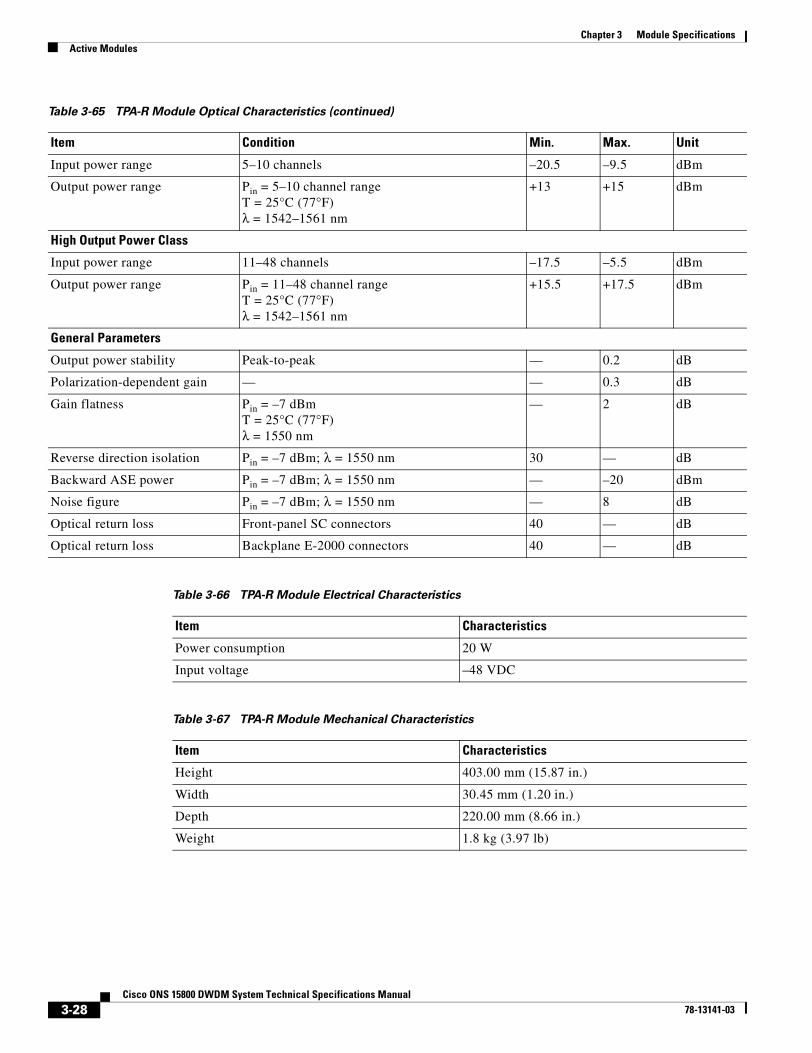
3-28Cisco ONS 15800 DWDM System Technical Specifications Manual
78-13141-03
Chapter 3 Module SpecificationsActive Modules
Input power range 5–10 channels –20.5 –9.5 dBm
Output power range Pin = 5–10 channel rangeT = 25°C (77°F)λ = 1542–1561 nm
+13 +15 dBm
High Output Power Class
Input power range 11–48 channels –17.5 –5.5 dBm
Output power range Pin = 11–48 channel rangeT = 25°C (77°F)λ = 1542–1561 nm
+15.5 +17.5 dBm
General Parameters
Output power stability Peak-to-peak — 0.2 dB
Polarization-dependent gain — — 0.3 dB
Gain flatness Pin = –7 dBmT = 25°C (77°F)λ = 1550 nm
— 2 dB
Reverse direction isolation Pin = –7 dBm; λ = 1550 nm 30 — dB
Backward ASE power Pin = –7 dBm; λ = 1550 nm — –20 dBm
Noise figure Pin = –7 dBm; λ = 1550 nm — 8 dB
Optical return loss Front-panel SC connectors 40 — dB
Optical return loss Backplane E-2000 connectors 40 — dB
Table 3-66 TPA-R Module Electrical Characteristics
Item Characteristics
Power consumption 20 W
Input voltage –48 VDC
Table 3-67 TPA-R Module Mechanical Characteristics
Item Characteristics
Height 403.00 mm (15.87 in.)
Width 30.45 mm (1.20 in.)
Depth 220.00 mm (8.66 in.)
Weight 1.8 kg (3.97 lb)
Table 3-65 TPA-R Module Optical Characteristics (continued)
Item Condition Min. Max. Unit

3-29Cisco ONS 15800 DWDM System Technical Specifications Manual
78-13141-03
Chapter 3 Module SpecificationsActive Modules
Optical Add/Drop Multiplexer ModuleOADM-P4 modules are used at 2.5-Gbps and 10-Gbps optical add/drop multiplexing sites for partial red-band demultiplexing. The last two characters of the module description designate the specific channels added and dropped. The OADM-P4 module is located in the OSR-W subrack. Optical characteristics of the module, including the specific channels added or dropped, are shown in Table 3-68. Electrical characteristics are shown in Table 3-69. Mechanical characteristics are shown in Table 3-70.
Table 3-68 OADM-P4 Module Optical Characteristics
Item Condition Min. Nom. Max. Unit
Module Parameters
OADM-P4-R1 add/drop frequencies
Channel 09Channel 11Channel 13Channel 15
— 1542.141543.731545.321546.92
— nm
OADM-P4-R3 add/drop frequencies
Channel 17Channel 19Channel 21Channel 23
— 1548.511550.121551.721553.33
— —
Transiting channel insertion loss OADM-P4-R1 and R3 4 — 7.5 dB
Dropped-channel insertion loss In drop path 6 — 10 dB
Insertion section insertion loss OADM-P4-R1 and R3 — — 7.5 dB
General Parameters
Dropped-channel bandwidth at -0.5 dB
— 0.3 — — nm
Adjacent crosstalk of dropped channels
— 25 — — dB
In-line suppression of dropped channels
— 25 — — dB
Optical return loss Input ports 40 — — dB
Table 3-69 OADM-P4 Module Electrical Characteristics
Item Characteristics
Power consumption 20 W maximum
Input voltage –48 VDC
Table 3-70 OADM-P4 Module Mechanical Characteristics
Item Characteristics
Height 403.00 mm (15.87 in.)
Width 30.45 mm (1.20 in.)
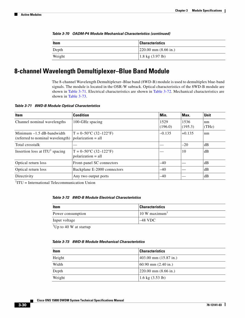
3-30Cisco ONS 15800 DWDM System Technical Specifications Manual
78-13141-03
Chapter 3 Module SpecificationsActive Modules
8-channel Wavelength Demultiplexer–Blue Band ModuleThe 8-channel Wavelength Demultiplexer–Blue band (8WD-B) module is used to demultiplex blue-band signals. The module is located in the OSR-W subrack. Optical characteristics of the 8WD-B module are shown in Table 3-71. Electrical characteristics are shown in Table 3-72. Mechanical characteristics are shown in Table 3-73.
Depth 220.00 mm (8.66 in.)
Weight 1.8 kg (3.97 lb)
Table 3-70 OADM-P4 Module Mechanical Characteristics (continued)
Item Characteristics
Table 3-71 8WD-B Module Optical Characteristics
Item Condition Min. Max. Unit
Channel nominal wavelengths 100-GHz spacing 1529(196.0)
1536(195.3)
nm(THz)
Minimum –1.5 dB-bandwidth (referred to nominal wavelength)
T = 0–50°C (32–122°F)polarization = all
–0.135 +0.135 nm
Total crosstalk — — –20 dB
Insertion loss at ITU1 spacing T = 0–50°C (32–122°F)polarization = all
— 10 dB
Optical return loss Front-panel SC connectors –40 — dB
Optical return loss Backplane E-2000 connectors –40 — dB
Directivity Any two output ports –40 — dB1ITU = International Telecommunication Union
Table 3-72 8WD-B Module Electrical Characteristics
Item Characteristics
Power consumption 10 W maximum1
Input voltage –48 VDC1Up to 40 W at startup
Table 3-73 8WD-B Module Mechanical Characteristics
Item Characteristics
Height 403.00 mm (15.87 in.)
Width 60.90 mm (2.40 in.)
Depth 220.00 mm (8.66 in.)
Weight 1.6 kg (3.53 lb)

3-31Cisco ONS 15800 DWDM System Technical Specifications Manual
78-13141-03
Chapter 3 Module SpecificationsActive Modules
24-channel Wavelength Demultiplexer–Red Band ModuleThe 24-channel Wavelength Demultiplexer–Red band (24WD-R) module is used to demultiplex red-band signals. The module is located in the OSR-W subrack. Optical characteristics of the module are shown in Table 3-74. Electrical characteristics are shown in Table 3-75. Mechanical characteristics are shown in Table 3-76.
24-channel Wavelength Demultiplexer–Low Loss–Red Band ModuleThe 24-channel Wavelength Demultiplexer–Low Loss–Red band (24WD-LLR) module is used to demultiplex 10-Gbps red-band signals module is located in the OSR-W subrack. Optical characteristics of the 24WD-LLR module are shown in Table 3-77. Electrical characteristics are shown in Table 3-78. Mechanical characteristics are shown in Table 3-79.
Table 3-74 24WD-R Module Optical Characteristics
Item Condition Min. Max. Unit
Channel nominal wavelengths 100-GHz spacing 1542.14(194.4)
1560.61(192.1)
nm(THz)
Minimum –1.5 dB-bandwidth (referred to nominal wavelength)
T = 0–50°C (32–122°F)polarization = all
–0.135 +0.135 nm
Total crosstalk — — –20 dB
Insertion loss at ITU spacing T = 0–50°C (32–122°F)polarization = all
— 13 dB
Optical return loss Front-panel SC connectors –40 — dB
Optical return loss Backplane E-2000 connector –40 — dB
Directivity Any 2 output ports –40 — dB
Table 3-75 24WD-R Module Electrical Characteristics
Item Characteristics
Power consumption 10 W maximum1
Input voltage –48 VDC1Up to 40 W at startup
Table 3-76 24WD-R Module Mechanical Characteristics
Item Characteristics
Height 403.00 mm (15.87 in.)
Width 91.35 mm (3.60 in.)
Depth 220.00 mm (8.66 in.)
Weight 2.40 kg (5.29 lb)

3-32Cisco ONS 15800 DWDM System Technical Specifications Manual
78-13141-03
Chapter 3 Module SpecificationsCommon Modules
Common ModulesThis section covers modules in the ONS 15800 system that handle power, supervision, and communications. The modules and the sections explaining them are referenced in Table 3-80.
Table 3-77 24WD-LLR Module Optical Characteristics
Item Condition Min. Max. Unit
Channel nominal wavelengths 100-GHz spacing 1542.14(194.4)
1561(192.05)
nm(THz)
Minimum –1.5 dB-bandwidth (referred to nominal wavelength)
T = 5–40°C (41–104°F)polarization = all
–0.120 +0.120 nm
Total crosstalk — — –20 dB
Insertion loss at ITU spacing T = 5–40°C (41–104°F)polarization = all
— 9 dB
Optical return loss Front-panel SC connectors –40 — dB
Optical return loss Backplane E-2000 connectors –40 — dB
Maximum PDL 1.5 dB BW 1.5 dB
Directivity Any two output ports –40 dB
Operating Temperature Range — 0 50 °C
Storage Temperature Range — –20 80 °C
Table 3-78 24WD-LLR Module Electrical Characteristics
Item Characteristics
Power consumption 10 W maximum1
Input voltage –48 VDC1Up to 40 W at startup
Table 3-79 24WD-LLR Module Mechanical Characteristics
Item Characteristics
Height 403.00 mm (15.87 in.)
Width 91.35 mm (3.60 in.)
Depth 220.00 mm (8.66 in.)
Weight 2.4 kg (5.29 lb)

3-33Cisco ONS 15800 DWDM System Technical Specifications Manual
78-13141-03
Chapter 3 Module SpecificationsCommon Modules
Battery Management ModuleThe Battery Management (BAT) module powers each OSR-W subrack at each site. It is a line conditioner and filter composed of three independent units:
• One frame (BATFRM), which is the mechanical structure inserted in the subrack. It holds two line conditioner and filter units (BATMOD).
• Two independently extractable BATMODs, each managing one of two independent external 48–VDC power supplies (BAT1 and BAT2)
The BAT module shares slot 17 in the OSR-W with the SCF module. Electrical characteristics of an individual BATMOD are shown inTable 3-81. BAT module mechanical characteristics are shown in Table 3-82.
Table 3-80 Common Modules
Type Module Where Shown
Power Battery Management (BAT) module Table 3-81
Control Control and Monitoring Processor (CMP-W) module Table 3-83
Control and Monitoring Processor (CMP-W-2E) module
Table 3-83
Subrack Common Functions (SCF) module Table 3-85
Communications External Orderwire Interface (EOI-W) module Table 3-87
Input/Output Card (IOC-W) module Table 3-90
Line Service Modem (LSM-W) module Table 3-92
Router Bridge Unit (RBU) module Table 3-95
Table 3-81 BAT Module Electrical Characteristics (for Each BATMOD Unit)
Item Condition Min. Max. Unit
Input voltage — –75 –36 VDC
Input voltage Polarity inversion — 200 VDC
Input absolute overvoltage On subbat unit — > 91 VDC
Output voltage — –58 –40 VDC
Output current No load or full load 0 15 ADC
Output power — — 450 W
Electrical isolation Between input or output voltages and mechanical ground
500 1500 VDC
Input overvoltage protection Subbat turns off –75 –80 VDC
Voltage restored BATMOD turns back on Input voltage < –75 to –80 VDC ±1 VDC
EMI specifications — NF EN 55022 paragraph 3CISPR 22 paragraph 4 Telcordia TR-NWT-001089
Filter attenuation (at 300 KHz) — 30 ±2 — dB

3-34Cisco ONS 15800 DWDM System Technical Specifications Manual
78-13141-03
Chapter 3 Module SpecificationsCommon Modules
Control and Monitoring Processor ModulesThe CMP-W and CMP-W-2E modules monitor and relay commands to ONS 15800 modules. They also provide an interface to supervisory software such as Cisco Photonics Local Terminal, the local craft interface software, Cisco Transport Manager (CTM), network management software, or other element management software. The CMP-W-2E has two Ethernet ports. Electrical characteristics of the modules are shown in Table 3-83. Mechanical characteristics are shown in Table 3-84.
Subrack Common Functions ModuleEach OSR-W subrack is equipped with a Subrack Common Functions (SCF) module, which shares slot 17 with the BAT module. The SCF module performs these functions:
• Powers and monitors fans
• Monitors BAT1 and BAT2 external power supplies
• Monitors the filtered power supplied to the internal power bus
• Manages the internal CBUS extension
• Summarizes the alarm status of the OSR-W subrack through LEDs
• Tests all LEDs on all modules in the OSR-W through a push-button interface
Table 3-82 BAT Module Mechanical Characteristics
Item Characteristics
Height 135.00 mm (5.31 in.)
Width 30.20 mm (1.18 in.)
Depth 220.00 mm (8.66 in.)
Weight 1.50 kg (3.31 lb)
Table 3-83 CMP-W and CMP-W-2E Module Electrical Characteristics
Item Characteristics
Power consumption (CMP-W) 36 W maximum
Power consumption (CMP-W-2E) 25 W maximum
Input voltage –48 VDC
Table 3-84 CMP-W and CMP-W-2E Module Mechanical Characteristics
Item Characteristics
Height 403.00 mm (15.87 in.)
Width (CMP-W) 30.45 mm (1.20 in.)
Width (CMP-W-2E) 30.2 mm (1.19 in.)
Depth 220.00 mm (8.66 in.)
Weight 1.0 kg (2.20 lb)

3-35Cisco ONS 15800 DWDM System Technical Specifications Manual
78-13141-03
Chapter 3 Module SpecificationsCommon Modules
Electrical characteristics of the SCF module are shown in Table 3-85. Mechanical characteristics are shown in Table 3-86.
External Orderwire Interface ModuleThe External Orderwire Interface (EOI-W) module provides an isolated interface between the Line Service Modem (LSM-W) and an external orderwire terminal. When deployed, the EOI-W module is located in the OSR-W subrack. Electrical characteristics of the module are shown in Table 3-87. Mechanical characteristics are shown in Table 3-88. Interface specifications are shown in Table 3-89.
Table 3-85 SCF Module Electrical Characteristics
Item Characteristics
Power consumption 5 W + 25 W1 maximum
Input voltage –48 VDC1 Due to the fans dissipation
Table 3-86 SCF Module Mechanical Characteristics
Item Characteristics
Height 268.00 mm (10.55 in.)
Width 30.45 mm (1.20 in.)
Depth 220.00 mm (8.66 in.)
Weight 0.50 kg (1.10 lb)
Table 3-87 EOI-W Module Electrical Characteristics
Item Characteristics
Power consumption 15 W maximum
Input voltage –48 VDC
Table 3-88 EOI-W Module Mechanical Characteristics
Item Characteristics
Height 403.00 mm (15.87 in.)
Width 30.45 mm (1.20 in.)
Depth 220.00 mm (8.66 in.)
Weight 1.28 kg (2.82 lb)

3-36Cisco ONS 15800 DWDM System Technical Specifications Manual
78-13141-03
Chapter 3 Module SpecificationsCommon Modules
Input/Output Card ModuleThe Input/Output Card (IOC-W) module protects NEs by reporting indications from externally sensed equipment and housekeeping alarms. The IOC-W module also enables remote control of isolated optical line amplification sites. When deployed, the IOC-W module is located in the OSR-W subrack. Electrical characteristics of the module are shown in Table 3-90. Mechanical characteristics are shown in Table 3-91.
Line Service Modem ModuleThe Line Service Modem (LSM-W) module is a bidirectional optical modem operating at 2.048 Mbps. It carries telemetry, supervision, and user-defined information, as well as orderwire communication in both directions over the OSC. Optical characteristics of the module are shown in Table 3-92. Electrical characteristics are shown in Table 3-93. Mechanical characteristics are shown in Table 3-94.
Table 3-89 EOI-W Interface Specifications
Module Interface Description
Front panel interface EIA/TIA-232 (RS-232)
Back panel interface EIA/TIA-232 (RS-232)
Ethernet interface Ethernet 10/100 Base-T controller
PC interface Type II and Type III
Table 3-90 IOC-W Module Electrical Characteristics
Item Characteristics
Power consumption 10 W maximum
Input voltage –48 VDC
Table 3-91 IOC-W Module Mechanical Characteristics
Item Characteristics
Height 403.00 mm (15.87 in.)
Width 30.45 mm (1.20 in.)
Depth 220.00 mm (8.66 in.)
Weight 1.28 kg (2.82 lb)
Table 3-92 LSM-W Module Optical Characteristics
Item Nom. Unit
OSC wavelength 1480 ±10 nm
OSC line bit rate 2.048 Mbps
OSC line interface ITU-T G.704 or ITU-T G.706 —
OSC line coding CMI1 —

3-37Cisco ONS 15800 DWDM System Technical Specifications Manual
78-13141-03
Chapter 3 Module SpecificationsCommon Modules
Router Bridge Unit ModuleWhen two ONS 15800 system routes are used redundantly in the system, a break in the OSC can be self-healed by the use of Router Bridge Unit (RBU) modules located at each end of the link (two terminal sites). Electrical characteristics of the module are shown in Table 3-95. Mechanical characteristics are shown in Table 3-96.
Telemetry LAN2 (28 x 64 Kbps) IEEE3 8802.3, 10Base2 (BNC4) —
E1/E2 orderwire (2 x 64 Kbps5) ANSI EIA/TIA-422 (RS-422) and ITU-T V.11 (counter directional clock, transmit side; co-directional clock, receive side)
—
F1 user channel (1 x 64 Kbps) ANSI EIA/TIA-422 (RS-422), ITU-T V.11, and ITU-T X.21 (counter directional clock, transmit side; co-directional clock, receive side)
—
Synchronization (1 x 64 Kbps) ANSI EIA/TIA-422 (RS-422), ITU-T V.11, and ITU-T X.21 (counter directional clock, transmit side; co-directional clock, receive side)
—
1CMI = coding method identifier2LAN = local area network3IEEE = Institute of Electrical and Electronics Engineers4BNC = British naval connector5Kbps = kilobits per second
Table 3-93 LSM-W Module Electrical Characteristics
Item Characteristics
Power consumption 33 W maximum
Input voltage –48 VDC
Table 3-94 LSM-W Module Mechanical Characteristics
Item Characteristics
Height 403.00 mm (15.87 in.)
Width 60.90 mm (1.20 in.)
Depth 220.00 mm (8.66 in.)
Weight 1.4 kg (3.09 lb)
Table 3-92 LSM-W Module Optical Characteristics (continued)
Item Nom. Unit
Table 3-95 RBU Module Electrical Characteristics
Item Characteristics
Power consumption 26 W maximum
Input voltage –48 VDC

3-38Cisco ONS 15800 DWDM System Technical Specifications Manual
78-13141-03
Chapter 3 Module SpecificationsPassive Modules
Passive ModulesThe passive modules in this section are different from active modules, because they do not have power connectors on their interfaces with the ONS 15800 system subracks. The passive modules of the system work with channels in specific bands.
1-channel Pass-through ModuleThe 1-channel Pass-through (1PT-W) module provides passive, direct connectivity for one input optical signal from the front face of the ONS 15800 platform into the cabling backbone of the ONS 15800 backplane without requiring equipment to be rewired. Optical characteristics of the module are shown in Table 3-97. Mechanical characteristics are shown in Table 3-98.
8-channel Wavelength Multiplexer–Blue Band ModuleThe 8-channel Wavelength Multiplexer–Blue band (8WM-B) module is used to multiplex the blue-band signals before amplification in the TPA-B module. The 8WM-B module is located in the Optical Multiplexer (OSR-MUX) subrack. Optical characteristics of the module are shown in Table 3-99. Mechanical characteristics of the module are shown in Table 3-100.
Table 3-96 RBU Module Mechanical Characteristics
Item Characteristics
Height 403.00 mm (15.87 in.)
Width 60.90 mm (1.20 in.)
Depth 220.00 mm (8.66 in.)
Table 3-97 1PT-W Module Optical Characteristics
Item Min. Max. Unit
Insertion loss 0.4 0.8 dB
Reflectance 40 dB
Table 3-98 1PT-W Module Mechanical Characteristics
Item Characteristics
Height 403.00 mm (15.87 in.)
Width 30.45 mm (1.20 in.)
Depth 220.00 mm (8.66 in.)
Weight 1.60 kg (3.53 lb)
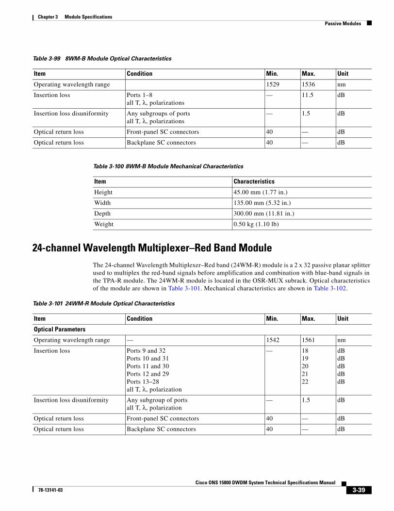
3-39Cisco ONS 15800 DWDM System Technical Specifications Manual
78-13141-03
Chapter 3 Module SpecificationsPassive Modules
24-channel Wavelength Multiplexer–Red Band ModuleThe 24-channel Wavelength Multiplexer–Red band (24WM-R) module is a 2 x 32 passive planar splitter used to multiplex the red-band signals before amplification and combination with blue-band signals in the TPA-R module. The 24WM-R module is located in the OSR-MUX subrack. Optical characteristics of the module are shown in Table 3-101. Mechanical characteristics are shown in Table 3-102.
Table 3-99 8WM-B Module Optical Characteristics
Item Condition Min. Max. Unit
Operating wavelength range 1529 1536 nm
Insertion loss Ports 1–8all T, λ, polarizations
— 11.5 dB
Insertion loss disuniformity Any subgroups of portsall T, λ, polarizations
— 1.5 dB
Optical return loss Front-panel SC connectors 40 — dB
Optical return loss Backplane SC connectors 40 — dB
Table 3-100 8WM-B Module Mechanical Characteristics
Item Characteristics
Height 45.00 mm (1.77 in.)
Width 135.00 mm (5.32 in.)
Depth 300.00 mm (11.81 in.)
Weight 0.50 kg (1.10 lb)
Table 3-101 24WM-R Module Optical Characteristics
Item Condition Min. Max. Unit
Optical Parameters
Operating wavelength range — 1542 1561 nm
Insertion loss Ports 9 and 32Ports 10 and 31Ports 11 and 30Ports 12 and 29Ports 13–28all T, λ, polarization
— 1819202122
dBdBdBdBdB
Insertion loss disuniformity Any subgroup of portsall T, λ, polarization
— 1.5 dB
Optical return loss Front-panel SC connectors 40 — dB
Optical return loss Backplane SC connectors 40 — dB

3-40Cisco ONS 15800 DWDM System Technical Specifications Manual
78-13141-03
Chapter 3 Module SpecificationsPassive Modules
Dispersion Compensating Unit ModuleDispersion Compensating Unit–Blue band (DCU-B) and Dispersion Compensating Unit–Red band (DCU-R) modules compensate for chromatic dispersion effects. A positive DCU module compensates for negative dispersion effects and a negative DCU module compensates for positive dispersion effects. DCU modules are mounted in Dispersion Compensating Unit Optical Subracks (OSR-DCU). Operating wavelengths of the DCU modules are shown in Table 3-103. DCU module compensation parameters are shown in Table 3-104. Mechanical characteristics are shown in Table 3-105.
Table 3-102 24WM-R Module Mechanical Characteristics
Item Characteristics
Height 45.00 mm (1.77 in.)
Width 265.00 mm (10.43 in.)
Depth 300.00 mm (11.81 in.)
Weight 1.00 kg (2.20 lb)
Table 3-103 DCU-B and DCU-R Module Operating Wavelengths
Band Range (nm) Reference (nm) Effect
Blue 1529–1536 1531.9 Positive or negative as needed
Red 1542–1561 1555.8 Positive or negative as needed
Table 3-104 DCU-B and DCU-R Module Variation Over Operating Temperature Range
Parameter Negative Compensation Positive Compensation
Dispersion value < ±1% < 4%
Dispersion slope ≤ 2% ±13%
Insertion loss ≤ 0.5 dB ≤ 0.5 dB
PMD < 10% < 10%
Table 3-105 DCU-B and DCU-R Module Mechanical Characteristics
Item Characteristics
Height 44.00 mm (1.73 in.)
Width 267.50 mm (10.53 in.)
Depth 291.00 mm (11.46 in.)
Weight Minimum 2.20 kg (4.85 lb); maximum 3.50 kg (7.72 lb)

3-41Cisco ONS 15800 DWDM System Technical Specifications Manual
78-13141-03
Chapter 3 Module SpecificationsAuxiliary Components
Optical Service Channel–Pass-Through ModuleThe Optical Service Channel–Pass-Through (OSC-PT-W) module provides passive Ethernet bus termination points. It is used instead of the RBU module when it is not required to perform OSC traffic bridging. Mechanical characteristics are shown in Table 3-106.
Auxiliary ComponentsAuxiliary components are not placed in subracks.
Gain-Flattening Filter–Red BandThe Gain-Flattening Filter–Red band (GFF-R) is used in all site types depending on span budget and fiber type. The module adjusts gain tilt between sites to bring the gain tilt within specifications. Optical characteristics are listed in Table 3-107.
Table 3-106 OSC-PT-W Module Mechanical Characteristics
Item Characteristics
Height 360.00 mm (14.18 in.)
Width 30.00 mm (1.18 in.)
Depth 220.00 mm (8.66 in.)
Weight 1.2 kg (2.64 lb)
Table 3-107 GFF-R Module Optical Characteristics
Item Condition Min. Max. Unit
Operating wavelength range — 1542 1562 nm
Minimum input loss value at 1542 nm — 1.5 dB
PMD — — 0.1 ps
PDL1 — — 0.1 dB
Maximum back-reflection Any port; other port terminated — –55 dB1PDL = polarization-dependent loss

3-42Cisco ONS 15800 DWDM System Technical Specifications Manual
78-13141-03
Chapter 3 Module SpecificationsAuxiliary Components

C H A P T E R
4-1Cisco ONS 15800 DWDM System Technical Specifications Manual
78-13141-03
4Supervision and Alarms
This chapter describes the supervisory modules and functions of the ONS 15800 system. It lists the alarm values for each system module.
Supervisory Modules
Note Although one network element generally corresponds to one site, one location may contain two or more NEs– if the location has a protected architecture or if it is a network interconnection point.
Network elements (NE) are supervised and administered by the Control and Monitoring Processor (CMP-W and CMP-W-2E) module, the heart of the ONS 15800 management system. In addition to controlling all of the optical and common modules at the site, the CMP module collects information about module status, alarms, parameters, and actions on one internal control bus. Each ONS 15800 NE contains at least one CMP module. The CMP module is described in the next section.
The Subrack Common Functions (SCF) module monitors subracks. Each ONS 15800 NE contains at least one SCF module. SCF modules are described after the Control and Monitoring Processor module.
Control and Monitoring Processor ModuleThe CMP module controls all optical and common modules in its NE; collects module status, alarms, parameters, and actions on one internal control bus; and provides this information through these interfaces:
• A serial EIA/TIA-232 (RS-232) port where the local craft terminal (Cisco Photonics Local Terminal software) can be connected (F interface)
• An Ethernet bus that connects to a local terminal (Cisco Photonics Local Terminal software via an Ethernet interface)
Subrack Common Functions ModuleThe Optical Subrack (OSR-W) is supervised and administered through the SCF module. All OSR-W subracks are equipped with an SCF module, which shares slot 17 with the Battery Management (BAT) module. The SCF performs these functions:
• Powers and monitors the fans

4-2Cisco ONS 15800 DWDM System Technical Specifications Manual
78-13141-03
Chapter 4 Supervision and AlarmsPerformance Management
• Manages BAT module (BAT1 and BAT2) external power supplies
• Monitors the filtered power supplied to the internal power bus
• Manages the internal control bus extension
• Summarizes the alarm status of the OSR-W subrack through LEDs
• Tests all LEDs on all modules through a push-button interface
Performance ManagementThe transponder modules that monitor the B1 byte of the SONET or synchronous digital hierarchy (SDH) frame provide performance monitoring for the ONS 15800 system. In addition some modules include forward error correction (FEC) to detect and correct errors on the dense wavelength division multiplexing (DWDM) channels. These performance-monitoring modules follow:
• Line Extender Module–Externally Modulated–B1 Monitoring (LEM-EM-Mxx)
• Line Extender Module–10 Gbps–B1 Monitoring (LEM-10G-Mxx)
• Line Extender Module–10 Gbps High-Output Power–B1 Monitoring (LEM-10H-Mxx)
• Receive Transponder–Directly Modulated–B1 Monitoring (RXT-DM-M) module
• Receive Transponder–Directly Modulated–Forward Error Correction (RXT-DM-F) module
• Receive Transponder–10 Gbps–B1 Monitoring (RXT-10G-M) module
• Receive Transponder–10 Gbps–Forward Error Correction (RXT-10G-F) module
• Wavelength Converter Module–Externally Modulated–B1 Monitoring (WCM-EM-Mxx)
• Wavelength Converter Module–Externally Modulated–Forward Error Correction (WCM-EM-Fxx)
• Wavelength Converter Module–10 Gbps–B1 Monitoring (WCM-10G-Mxx)
• Wavelength Converter Module–10 Gbps High-Output Power–B1 Monitoring (WCM-10H-Mxx)
• Wavelength Converter Module–10 Gbps–Forward Error Correction (WCM-10G-Fxx)
Measurement of NE operating performance can be activated, stopped, and scheduled in user-defined intervals. Intervals can be set in increments of minutes (valid values are 15-to-1440 in multiples of 15), hours (valid values are 1-to-24), or days (valid values are 1-to-31) as specified by ITU-T G.826 and ITU-T G.784. Performance statistics are stored in an embedded database as a performance report and managed through an installed network management agent. Performance management parameters monitored by these modules are listed in Table 4-1.
The following FEC transponder modules do not monitor the B1 byte of the SONET or SDH frame but do provide FEC performance monitoring for the ONS 15800 system:
• Line Extender Module–Externally Modulated–Forward Error Correction (LEM-EM-Fxx)
Table 4-1 Performance Management Parameters
Parameter Description
ES Errored seconds
SES Severely errored seconds
BBE Background block errors
UAS Unavailable seconds

4-3Cisco ONS 15800 DWDM System Technical Specifications Manual
78-13141-03
Chapter 4 Supervision and AlarmsLocal Craft Interface
• Line Extender Module–10 Gbps–Forward Error Correction (LEM-10G-Fxx)
Local Craft InterfaceThe Cisco Photonics Local Terminal software is designed to supervise and maintain the ONS 15800 system. Cisco Photonics Local Terminal software is implemented on a personal computer and can be connected to any site of the ONS 15800 system through a local EIA/TIA 232 (RS-232) serial interface or an Ethernet interface. When the software is connected through the EIA/TIA-232 interface, only the local site is visible. When the software is connected through an Ethernet interface, diagnostic functions can be performed on all linked sites. The main features of Cisco Photonics Local Terminal software follow:
• Local supervision of a site, including element-by-element monitoring of fault reports and alarm status, NE parameter configuration, and element-by-element system performance supervision
• Remote supervision of sites linked to the local site
• Easy-to-use Windows-based graphical user interface (GUI)
• PC-based platform
Housekeeping Alarm ManagementHousekeeping alarms in the ONS 15800 system are managed and reported by the Input/Output Card (IOC-W) module. The IOC-W module reports indications from externally sensed conditions. The conditions include DC power problems, fire, flood, and open bay doors. For more information about the IOC-W module, see Chapter 3, “Module Specifications.”
Module AlarmsAlarm data for ONS 15800 system modules that have associated alarms are listed in Table 4-2 through Table 4-59. For more information about these modules, see Chapter 3, “Module Specifications.”
Table 4-2 8WD-B Module Analog Alarms
Item Name Unit Type Criteria Threshold Value Unit Severity
Operating temperature T °C Degrade Low Top – 3 °C Minor
T °C Degrade Low Top – 15 °C Major
T °C Degrade High Top + 15 °C Major
T °C Degrade High Top + 3 °C Minor
T °C (°F) Fail Low –50 (–58) °C (°F) Critical
T °C (°F) Fail High +120 (+248) °C (°F) Critical
Input power InpPwr1 dBm Degrade Low TBD µW (dBm) Minor
InpPwr1 dBm Fail Low –34 µW (dBm) Critical
InpPwr1 dBm Degrade High TBD µW (dBm) Minor

4-4Cisco ONS 15800 DWDM System Technical Specifications Manual
78-13141-03
Chapter 4 Supervision and AlarmsModule Alarms
Table 4-3 8WD-B Module Digital Alarms
Item Name Set Point Reference Threshold Severity
POW_IN POW_In Low Digital input High Critical
IPO_OUT IPO_Out High Digital output (PBUS) Low Critical
Safety disabled Safety disabled False Digital flag True Warning
Table 4-4 24WD-LLR Module Analog Alarms
Item Name Unit Type Criteria Threshold Value Unit Severity
Operating temperature T °C Degrade Low Top – 3 °C Minor
T °C Degrade Low Top – 15 °C Major
T °C Degrade High Top + 15 °C Major
T °C Degrade High Top + 3 °C Minor
T °C (°F) Fail Low –50 (–58) °C (°F) Critical
T °C (°F) Fail High +120 (+248) °C (°F) Critical
Table 4-5 24WD-LLR Module Digital Alarms
Item Name Set Point Reference Threshold Severity
POW_IN Pow_In Low Digital input High Critical
IPO_OUT IPO_Out High Digital output (PBUS) Low Critical
Safety disabled Safety disabled False Digital flag True Warning
Table 4-6 24WD-R Module Analog Alarms
Item Name Unit Type Criteria Threshold Value Unit Severity
Operating temperature T °C Degrade Low Top – 3 °C Minor
T °C Degrade Low Top – 15 °C Major
T °C Degrade High Top + 15 °C Major
T °C Degrade High Top + 3 °C Minor
T °C (°F) Fail Low –50 (–58) °C (°F) Critical
T °C (°F) Fail High +120 (+248) °C (°F) Critical
Input power InpPwr1 dBm Degrade Low –34 µW Minor
InpPwr1 dBm Fail Low TBD µW Critical
InpPwr1 dBm Degrade High TBD µW Minor

4-5Cisco ONS 15800 DWDM System Technical Specifications Manual
78-13141-03
Chapter 4 Supervision and AlarmsModule Alarms
Table 4-7 24WD-R Module Digital Alarms
Item Name Set Point Reference Threshold Severity
POW_IN Pow_In Low Digital input High Critical
IPO_OUT IPO_Out High Digital output (PBUS) Low Critical
Safety disabled Safety disabled False Digital flag True Warning
Table 4-8 ADA Module Analog Alarms
Item Name
MorC1
Set Point(Controlled Items) Alarm
Value Unit Type Criteria Threshold Value Unit Severity
Laser1operatingtemp.
LasTemp1 C 25 (77) °C (°F) Degrade Low 22 (71.6) °C (°F) Minor
LasTemp1 C 25 (77) °C (°F) Degrade High 28 (82.4) °C (°F) Minor
Laser2operatingtemp.
LasTemp2 C 25 (77) °C (°F) Degrade Low 22 (71.6) °C (°F) Minor
LasTemp2 C 25 (77) °C (°F) Degrade High 28 (82.4) °C (°F) Minor
Laser 1current
LasCur1 M I_op mA Degrade High I_op * 1.1 mA Minor
LasCur1 M I_op mA Fail High 290 mA Major
LasCur1 M I_op mA Fail Low 10 mA Major
Laser 2current
LasCur2 M I_op mA Degrade High I_op * 1.1 mA Minor
LasCur2 M I_op mA Fail High 290 mA Major
LasCur2 M I_op mA Fail Low 10 mA Major
Laser 1power
LasPow1 M 90 mW Degrade Low P_op * 0.8 mW Minor
LasPow1 M 90 mW Fail Low 5 mW Critical
Laser 2power
LasPow2 M 90 mW Degrade Low P_op * 0.8 mW Minor
LasPow2 M 90 mW Fail Low 5 mW Critical
Inputpower 1
InpPwr1 M – dBm Degrade Low 31.62 µW Minor
InpPwr1 M – dBm Fail Low 10 µW Critical
Inputpower 2
InpPwr2 M – dBm Degrade Low 31.62 µW Minor
InpPwr2 M – dBm Fail Low 10 µW Critical
Outputpower 1
OutPwr1 C – dBm Degrade Low 1 mW Minor
OutPwr1 C – dBm Fail Low 0.250 mW Critical
Outputpower 2
OutPwr2 C – dBm Degrade Low 1 mW Minor
OutPwr2 C – dBm Fail Low 0.250 mW Critical1Monitored or controlled

4-6Cisco ONS 15800 DWDM System Technical Specifications Manual
78-13141-03
Chapter 4 Supervision and AlarmsModule Alarms
Table 4-9 BBA Module Analog Alarms
Item Name
MorC1
Set Point (Controlled Items) Alarm
Value Unit Ref. Type Criteria T2 Value Unit Severity
Inputpower
InpPwr1 M – dBm – Degrade Low 50 (–13) µW (dBm) Minor
InpPwr1 M – dBm – Fail Low 39.8 (–14) µW (dBm) Critical
InpPwr1 M – dBm – Degrade High 4467 (6.5) µW (dBm) Minor
Outputpower
OutPwr1 M 33.5 (15.25) mW (dBm) High class Degrade Low 0.7 * WP mW Minor
OutPwr1 M 25.12 (14) mW (dBm) Mid class Fail Low 6.31 mW Critical
OutPwr1 M 15.85 (12) mW (dBm) Low class Degrade High 1.42 * WP mW Minor
Laserpower
LasPow1 C 903 Mw High class Degrade Low P_op * 0.9 mW Minor
LasPow1 C 80 mW Mid class Fail Low 10 mW Critical
Las Pow1 C 50 mW Low class Degrade High P_op * 1.1 mW Minor
Lasercurrent
LasCur1 M I_op mA Operatingcurrenthigh class
Degrade High I_op * 1.1 mA Minor
LasCur1 M I_op mA Operatingcurrenthigh class
Fail High 290 mA Major
LasCur1 M I_op mA Operatingcurrenthigh class
Degrade Low 25 mA Minor
Laseroperatingtemp.
LasTemp1 C 25 (77) °C (°F) – Degrade Low 22 (71.6) °C (°F) Minor
LasTemp1 C 25 (77) °C (°F) – Degrade High 28 (82.4) °C (°F) Minor
1Monitored or controlled2Threshold3Variable according to laser type
Table 4-10 BBA Module Digital Alarms
Item Name Alarm Type
Shutdown relay RelLasOff1 Monitored
Laser status LasStat1 Monitored
Site location Site Monitored

4-7Cisco ONS 15800 DWDM System Technical Specifications Manual
78-13141-03
Chapter 4 Supervision and AlarmsModule Alarms
Table 4-11 BBA-10G Module Analog Alarms
Item Name
MorC1
Set Point (Controlled Items) Alarm
Value Unit Ref. Type Criteria T2 Value Unit Severity
Inputpower
InpPwr1 M – dBm – Degrade Low 35 (–14.5) µW (dBm) Minor
InpPwr1 M – dBm – Fail Low 20 (–17) µW (dBm) Critical
InpPwr1 M – dBm – Degrade High 4467 (6.5) µW (dBm) Minor
Outputpower
OutPwr1 M 33.5 (15.25) mW (dBm) High class Degrade Low 0.66 * WP mW Minor
OutPwr1 M 25.12 (14) mW (dBm) Mid class Fail Low 6.31 mW Critical
OutPwr1 M 15.85 (12) mW (dBm) Low class Degrade High 1.5 * WP mW Minor
Laser 1power
LasPow1 C 75 mW All powerclasses
Degrade Low P_op * 0.9 mW Minor
LasPow1 C 75 mW All powerclasses
Fail Low 10 mW Critical
LasPow1 C 75 mW All powerclasses
Degrade High P_op * 1.1 mW Minor
Laser 2power
LasPow2 C 90 mW High classWP
Degrade Low P_op * 0.9 mW Minor
LasPow2 C 60 mW Mid classWP
Fail Low 10 mW Critical
LasPow2 C 32.5 mW Low classWP
Degrade High P_op * 1.1 mW Minor
Laser 1current
LasCur1 M I_op mA Operatingcurrenthigh class
Degrade High I_op * 1.15 mA Minor
LasCur1 M I_op mA Operatingcurrenthigh class
Fail High 290 mA Major
LasCur1 M I_op mA Operatingcurrenthigh class
Degrade Low 25 mA Minor
Laser 2current
LasCur2 M I_op mA Operatingcurrenthigh class
Degrade High I_op * 1.15 mA Minor
LasCur2 M I_op mA Operatingcurrenthigh class
Fail High 290 mA Major
LasCur2 M I_op mA Operatingcurrenthigh class
Degrade Low 25 mA Minor
Laser1operatingtemp.
LasTemp1 C 25 (77) °C (°F) – Degrade Low 22 (71.6) °C (°F) Minor
LasTemp1 C 25 (77) °C (°F) – Degrade High 28 (82.4) °C (°F) Minor

4-8Cisco ONS 15800 DWDM System Technical Specifications Manual
78-13141-03
Chapter 4 Supervision and AlarmsModule Alarms
Laser2operatingtemp.
LasTemp2 C 25 (77) °C (°F) – Degrade Low 22 (71.6) °C (°F) Minor
LasTemp2 C 25 (77) °C (°F) – Degrade High 28 (82.4) °C (°F) Minor
1Monitored or controlled2Threshold3Variable according to laser type
Table 4-12 BBA-10G Module Digital Alarms
Item Name Alarm Type
Shutdown relay RelLasOff1 Monitored
Laser status LasStat1 Monitored
Site location Site Monitored
Table 4-13 EOI-W Module Digital Alarm
Item Name Alarm Type
Set Point(Controlled Items) Alarm
Value Threshold Severity
Isolated power status IsoPowMon1 Monitored Off On Minor
Table 4-14 IOC-W Module Analog Alarms
Item Name Alarm Type Severity
Generic analog input (8) GenAnIn 1–8 Controlled Not defined
Table 4-15 IOC-W Module Digital Alarms
Item Name Alarm Type Severity
Generic digital output (20) GenDigOut 1–20 Controlled Not defined
Generic digital input (32) GenDigIn 1–32 Controlled Not defined
Table 4-11 BBA-10G Module Analog Alarms (continued)
Item Name
MorC1
Set Point (Controlled Items) Alarm
Value Unit Ref. Type Criteria T2 Value Unit Severity

4-9Cisco ONS 15800 DWDM System Technical Specifications Manual
78-13141-03
Chapter 4 Supervision and AlarmsModule Alarms
Table 4-16 LEM-EM-Mxx Module Analog Alarms
Item Name
MorC1
Set Point(Controlled Items) Alarm
Value Unit Type Criteria Threshold Value Unit Severity
Lasertemp.
LasTemp1 C T_op °C Fail Low T_op–2 °C Major
LasTemp1 C T_op °C Fail High T_op + 2 °C Major
Lasercurrent
LasCurr1 C I_op mA Degrade High I_op * 1.2 mA Minor
LasCurr1 C I_op mA Fail High I_op * 1.4 = 140 ma mA Major
Laserpower
LasPow1 C P_op mW Degrade Low P_op * 0.8 mW Minor
LasPow1 C P_op mW Degrade High P_op * 1.2 mW Minor
Outputpower
OutPwr1 M (1) 0 mW (dBm) Degrade Low 0.79 (–1) mW (dBm) Minor
OutPwr1 M (1) 0 mW (dBm) Degrade High 1.26 (1) mW (dBm) Minor
Inputpower
InpPwr1 M – – Fail Low 0.0025 (–29) mW (dBm) Major
InpPwr1 M – – Fail High 0.2 (–7) mW (dBm) Major1Monitored or controlled
Table 4-17 LEM-EM-Mxx Module Digital Alarms
Item Name Alarm TypeSet PointValue
AlarmValue Severity
Loss of signal LosStatus1 Controlled Off On Major
Output modulation fail ModoutStat1 Controlled On Off Major
Input modulation fail ModinStat1 Controlled On Off Major
IPO in IpoinStat1 Controlled – – Not defined
IPO out IpooutStat1 Controlled – – Not defined
OPIN OpinStat Controlled – – Not defined
PinLow PinlowStat1 Controlled Off On Major
Shutdown relay RelLasOff1 Monitored – – –
Table 4-18 LEM-EM-Fxx Module Analog Alarms
Item Name
MorC1
Set Point(Controlled Items) Alarm
Value Unit Type Criteria Threshold Value Unit Severity
Lasertemp.
LasTemp1 C T_op °C Fail Low T_op–2 °C Major
LasTemp1 C T_op °C Fail High T_op + 2 °C Major
Lasercurrent
LasCurr1 M I_op mA Degrade High I_op * 1.2 mA Minor
LasCurr1 M I_op mA Fail High I_op * 1.4 = 140 ma mA Major
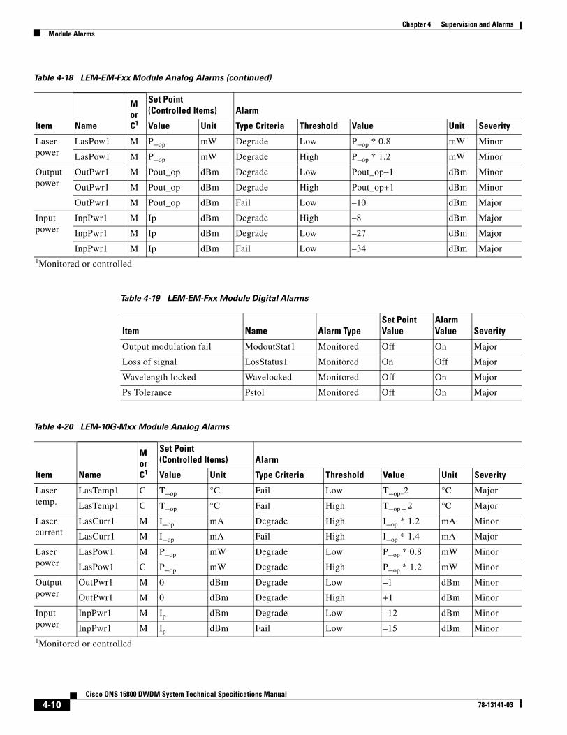
4-10Cisco ONS 15800 DWDM System Technical Specifications Manual
78-13141-03
Chapter 4 Supervision and AlarmsModule Alarms
Laserpower
LasPow1 M P_op mW Degrade Low P_op * 0.8 mW Minor
LasPow1 M P_op mW Degrade High P_op * 1.2 mW Minor
Outputpower
OutPwr1 M Pout_op dBm Degrade Low Pout_op–1 dBm Minor
OutPwr1 M Pout_op dBm Degrade High Pout_op+1 dBm Minor
OutPwr1 M Pout_op dBm Fail Low –10 dBm Major
Inputpower
InpPwr1 M Ip dBm Degrade High –8 dBm Major
InpPwr1 M Ip dBm Degrade Low –27 dBm Major
InpPwr1 M Ip dBm Fail Low –34 dBm Major1Monitored or controlled
Table 4-19 LEM-EM-Fxx Module Digital Alarms
Item Name Alarm TypeSet PointValue
AlarmValue Severity
Output modulation fail ModoutStat1 Monitored Off On Major
Loss of signal LosStatus1 Monitored On Off Major
Wavelength locked Wavelocked Monitored Off On Major
Ps Tolerance Pstol Monitored Off On Major
Table 4-20 LEM-10G-Mxx Module Analog Alarms
Item Name
MorC1
Set Point (Controlled Items) Alarm
Value Unit Type Criteria Threshold Value Unit Severity
Lasertemp.
LasTemp1 C T_op °C Fail Low T_op–2 °C Major
LasTemp1 C T_op °C Fail High T_op + 2 °C Major
Lasercurrent
LasCurr1 M I_op mA Degrade High I_op * 1.2 mA Minor
LasCurr1 M I_op mA Fail High I_op * 1.4 mA Major
Laserpower
LasPow1 M P_op mW Degrade Low P_op * 0.8 mW Minor
LasPow1 C P_op mW Degrade High P_op * 1.2 mW Minor
Outputpower
OutPwr1 M 0 dBm Degrade Low –1 dBm Minor
OutPwr1 M 0 dBm Degrade High +1 dBm Minor
Inputpower
InpPwr1 M Ip dBm Degrade Low –12 dBm Minor
InpPwr1 M Ip dBm Fail Low –15 dBm Minor1Monitored or controlled
Table 4-18 LEM-EM-Fxx Module Analog Alarms (continued)
Item Name
MorC1
Set Point(Controlled Items) Alarm
Value Unit Type Criteria Threshold Value Unit Severity

4-11Cisco ONS 15800 DWDM System Technical Specifications Manual
78-13141-03
Chapter 4 Supervision and AlarmsModule Alarms
Table 4-21 LEM-10G-Mxx Module Digital Alarms
Item Name Alarm TypeSet PointValue
AlarmValue Severity
Output modulation fail ModoutStat1 Monitored On Off Major
IPO in IpoinStat1 Monitored On Off Major
IPO out IpooutStat1 Monitored On Off Major
OPIN OpinStat Monitored Off On Major
Loss of signal Los Status Monitored On On Major
pinlow Pinlowstat1 Monitored Off On Major
Table 4-22 LEM-10H-Mxx Module Analog Alarms
Item Name
MorC1
Set Point (Controlled Items) Alarm
Value Unit Type Criteria Threshold Value Unit Severity
Lasertemp.
LasTemp1 C T_op °C Fail Low T_op–2 °C Major
LasTemp1 C T_op °C Fail High T_op + 2 °C Major
Lasercurrent
LasCurr1 M I_op mA Degrade High I_op * 1.2 mA Minor
LasCurr1 M I_op mA Fail High I_op * 1.4 mA Major
Laserpower
LasPow1 M P_op mW Degrade Low P_op * 0.8 mW Minor
LasPow1 M P_op mW Degrade High P_op * 1.2 mW Minor
Outputpower
OutPwr1 M 0 dBm Degrade Low 1.58(2)
mW(dBm)
Minor
OutPwr1 M 0 dBm Degrade High 2.51(4)
mw(dBm)
Minor
Inputpower
InpPwr1 M Ip dBm Degrade Low –12 dBm Minor
InpPwr1 M Ip dBm Fail Low –15 dBm Major1Monitored or controlled
Table 4-23 LEM-10H-Mxx Module Digital Alarms
Item Name Alarm TypeSet PointValue
AlarmValue Severity
Output modulation fail ModoutStat1 Monitored On Off Major
IPO in IpoinStat1 Monitored On Off Major
IPO out IpooutStat1 Monitored On Off Major
OPIN OpinStat Monitored Off On Major
Loss of signal Los Status Monitored On On Major
pinlow Pinlowstat1 Monitored Off On Major

4-12Cisco ONS 15800 DWDM System Technical Specifications Manual
78-13141-03
Chapter 4 Supervision and AlarmsModule Alarms
Table 4-24 LEM-10G-Fxx Module Analog Alarms
Item Name
MorC1
Set Point (Controlled Items) Alarm
Value Unit Type Criteria Threshold Value Unit Severity
Lasertemp.
LasTemp1 C T_op °C Fail Low T_op–2 °C Major
LasTemp1 C T_op °C Fail High T_op + 2 °C Major
Lasercurrent
LasCurr1 M I_op mA Degrade High I_op * 1.2 mA Minor
LasCurr1 M I_op mA Fail High I_op * 1.4 mA Major
Laserpower
LasPow1 M P_op mW Degrade Low P_op * 0.8 mW Minor
LasPow1 M P_op mW Degrade High P_op * 1.2 mW Minor
Outputpower
OutPwr1 M Pout_op dBm Degrade Low Pout_op –1 dBm Minor
OutPwr1 M Pout_op dBm Degrade High Pout_op +1 dBm Minor
OutPwr1 M Pout_op dBm Fail Low –10 dBm Major
Inputpower
InpPwr1 M Ip dBm Degrade High 0 dBm Minor
InpPwr1 M Ip dBm Degrade Low –12 dBm Minor
InpPwr1 M Ip dBm Fail Low –15 dBm Major1Monitored or controlled
Table 4-25 LEM-10G-Fxx Module Digital Alarms
Item Name Alarm TypeSet PointValue
AlarmValue Severity
Output modulation fail ModoutStat1 Monitored On Off Major
Loss of signal Los Status Monitored On Off Major
Wavelength locked WaveLocked Monitored On Off Major
OPIN OpinStat Monitored Off On Major
PsTolerance Pstolerance Monitored On Off Major
Table 4-26 LSM-W Module Analog Alarms
Item Name
MorC1
Set Point(Controlled Items) Alarm
Value Unit Type Criteria Threshold Value Unit Severity
East laserpower
ElasOutPwr1 C 5 mW Degrade Low 4 mW Minor
ElasOutPwr1 C 5 mW Degrade High 6 mW Minor
West laserpower
WlasOutPwr2 C 5 mW Degrade Low 4 mW Minor
WlasOutPwr2 C 5 mW Degrade High 6 mW Minor
East lasercurrent
ElasCurr1 C Iop mA Low Low EI_min mA Minor
ElasCurr1 C Iop mA High High EI_max mA Major

4-13Cisco ONS 15800 DWDM System Technical Specifications Manual
78-13141-03
Chapter 4 Supervision and AlarmsModule Alarms
West laserpower
WlasCurr2 C Iop mA Low Low WI_min mA Minor
WlasCurr2 C Iop mA High High WI_max mA Major
East lasertemp.
ElasTemp1 C 25 (77) °C (°F) Low Low ET_op – 2 °C (°F) Minor
ElasTemp1 c 25 (77) °C (°F) High High ET_op + 2 °C (°F) Minor
West lasertemp.
WlasTemp2 C 25 (77) °C (°F) Low Low WT_op – 2 °C (°F) Minor
WlasTemp2 C 25 (77) °C (°F) High High WT_op + 2 °C (°F) Minor1Monitored or controlled
Table 4-27 LSM-W Module Digital Alarms
Item Name Alarm TypeSet PointValue
AlarmValue Severity
East transmit master Emst Controlled Off On Warning
West transmit master WMst Controlled Off On Warning
East transmit remote al. ind. EraiTx Controlled Off On Warning
West transmit remote al. ind. WraiTx Controlled Off On Warning
East transmit aux. pattern EauxPTx Controlled Off On Warning
West transmit aux. pattern WauxPTx Controlled Off On Warning
East receive remote al. ind. EraiRx Controlled Off On Warning
West receive remote al. ind. WraiRx Controlled Off On Warning
East receive aux. pattern EauxPRx Controlled Off On Warning
West receive aux. pattern WauxPRx Controlled Off On Warning
East receive loss of frame alignment ElfaRx Controlled Off On Warning
West receive loss of frame alignment WlfaRx Controlled Off On Minor
East receive loss of signal ElosRx Controlled Off On Minor
West receive loss of signal WlosRx Controlled Off On Minor
East receive idle EidleRx Controlled Off On Minor
West receive idle WidleRx Controlled Off On Minor
Inconsistent config. CfgFail Controlled Off On Warning
DPRAM fail DprFail Controlled Off On Major
Table 4-26 LSM-W Module Analog Alarms (continued)
Item Name
MorC1
Set Point(Controlled Items) Alarm
Value Unit Type Criteria Threshold Value Unit Severity

4-14Cisco ONS 15800 DWDM System Technical Specifications Manual
78-13141-03
Chapter 4 Supervision and AlarmsModule Alarms
Table 4-28 OADM-P4 Module Analog Alarms
Item Name
MorC1
Set Point(Controlled Items) Alarm
Value Unit Type Criteria Threshold Value Unit Severity
OADM-P4-R1
BGF2 operatingtemp.
BGF2 C 25 (77) °C (°F) Degrade Low 24 (75.2) °C (°F) Minor
C 25 (77) °C (°F) Degrade High 26 (78.8) °C (°F) Minor
OADM-P4-R3
BGF2 operatingtemp.
BGF2 C 25 (77) °C (°F) Degrade Low 24 (75.2) °C (°F) Minor
C 25 (77) °C (°F) Degrade High 26 (78.8) °C (°F) Minor1Monitored or controlled
Table 4-29 OADM-P4 Module Digital Alarms
Item Name Alarm Type
Shutdown relay RelLasOff1 Monitored
Table 4-30 OSU-W Module Default Parameter Settings
Parameter State Setting
Enabling external line (Eel) Disable 1
Unit operating mode (Uom) AUTO 1
Unit forced state (Ufs) Working 0
Revertive (Rev) ON 1
Operating optical window Transmit side (WvlTx) 1550 nm 0
Operating optical window Receive side (WvlRx) 1550 nm 0
Hold-off time for internal Working line (HotW) 0 ms 0
Hold-off time for internal Protection line (HotP) 0 ms 0
Threshold PhotoDiode Working line input power (ThPDW)
–15 dBm 0.0316
Threshold PhotoDiode Protect line input power (ThPDP)
–15 dBm 0.0316
Switch insertion loss, Receive side threshold (Sil_Rx) 4 dB (0.399 in linear) 0.399
Power input, Transmit gain (Pin_Tx) 1 1
Power input Working Receive Transponder gain (PinW_RXT)
1 1
Power input Protection Receive Transponder gain (PinP_RXT)
1 1
Power output Receive gain (Pout_RX) 1 1
Number of the channel Protected (N_ch_P) 0 0
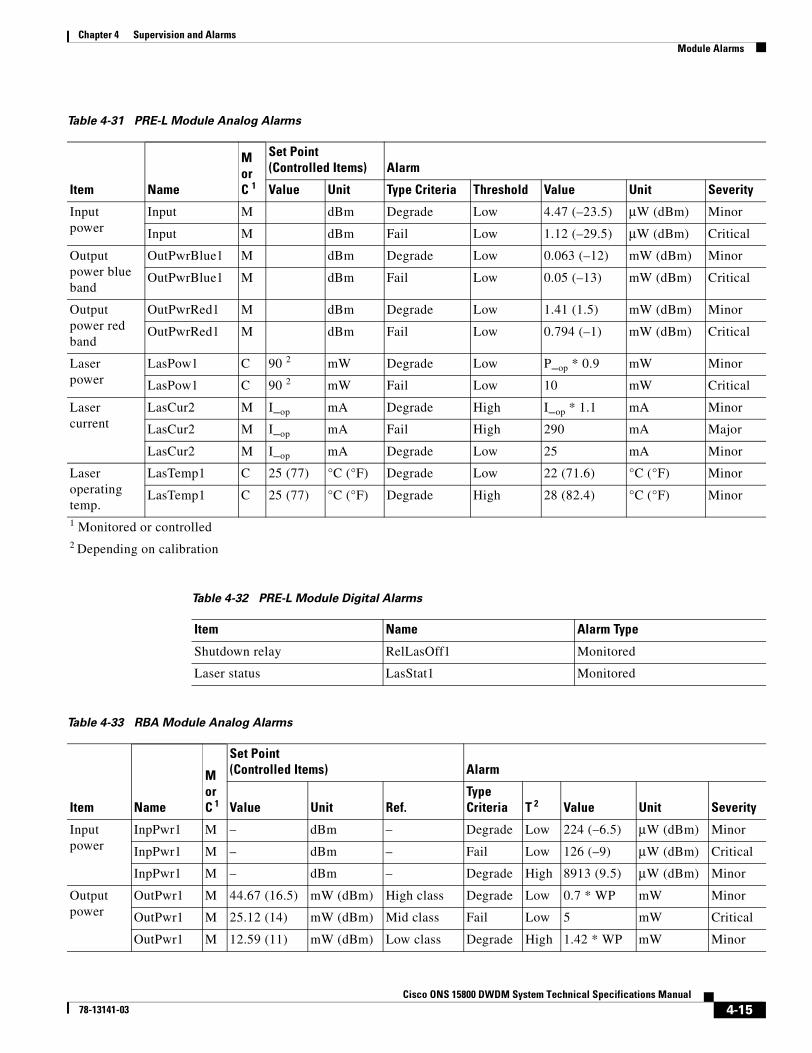
4-15Cisco ONS 15800 DWDM System Technical Specifications Manual
78-13141-03
Chapter 4 Supervision and AlarmsModule Alarms
Table 4-31 PRE-L Module Analog Alarms
Item Name
MorC 1
Set Point(Controlled Items) Alarm
Value Unit Type Criteria Threshold Value Unit Severity
Inputpower
Input M dBm Degrade Low 4.47 (–23.5) µW (dBm) Minor
Input M dBm Fail Low 1.12 (–29.5) µW (dBm) Critical
Outputpower blueband
OutPwrBlue1 M dBm Degrade Low 0.063 (–12) mW (dBm) Minor
OutPwrBlue1 M dBm Fail Low 0.05 (–13) mW (dBm) Critical
Outputpower redband
OutPwrRed1 M dBm Degrade Low 1.41 (1.5) mW (dBm) Minor
OutPwrRed1 M dBm Fail Low 0.794 (–1) mW (dBm) Critical
Laserpower
LasPow1 C 90 2 mW Degrade Low P_op * 0.9 mW Minor
LasPow1 C 90 2 mW Fail Low 10 mW Critical
Lasercurrent
LasCur2 M I_op mA Degrade High I_op * 1.1 mA Minor
LasCur2 M I_op mA Fail High 290 mA Major
LasCur2 M I_op mA Degrade Low 25 mA Minor
Laseroperatingtemp.
LasTemp1 C 25 (77) °C (°F) Degrade Low 22 (71.6) °C (°F) Minor
LasTemp1 C 25 (77) °C (°F) Degrade High 28 (82.4) °C (°F) Minor
1 Monitored or controlled2 Depending on calibration
Table 4-32 PRE-L Module Digital Alarms
Item Name Alarm Type
Shutdown relay RelLasOff1 Monitored
Laser status LasStat1 Monitored
Table 4-33 RBA Module Analog Alarms
Item Name
MorC 1
Set Point(Controlled Items) Alarm
Value Unit Ref.TypeCriteria T 2 Value Unit Severity
Inputpower
InpPwr1 M – dBm – Degrade Low 224 (–6.5) µW (dBm) Minor
InpPwr1 M – dBm – Fail Low 126 (–9) µW (dBm) Critical
InpPwr1 M – dBm – Degrade High 8913 (9.5) µW (dBm) Minor
Outputpower
OutPwr1 M 44.67 (16.5) mW (dBm) High class Degrade Low 0.7 * WP mW Minor
OutPwr1 M 25.12 (14) mW (dBm) Mid class Fail Low 5 mW Critical
OutPwr1 M 12.59 (11) mW (dBm) Low class Degrade High 1.42 * WP mW Minor

4-16Cisco ONS 15800 DWDM System Technical Specifications Manual
78-13141-03
Chapter 4 Supervision and AlarmsModule Alarms
Laser 1power
LasPow1 C 110 mW High class Degrade Low P_op * 0.9 mW Minor
LasPow1 C 55 mW Mid class Fail Low 10 mW Critical
LasPow1 C 28 mW Low class Degrade High P_op *1.1 mW Minor
Laser 2power
LasPow2 C 110 mW High class Degrade Low P_op * 0.95 mW Minor
LasPow2 C 55 mW Mid class Fail Low 10 mW Critical
LasPow2 C 25 mW Low class Degrade High P_op *1.1 mW Minor
Laser 1current
LasCur1 M I_op mA Operatingcurrent highclass
Degrade High I_op * 1.1 mA Minor
LasCur1 M I_op mA Operatingcurrent highclass
Fail High 290 mA Major
LasCur1 M I_op mA Operatingcurrent highclass
Degrade Low 25 mA Minor
Laser 2current
LasCur2 M I_op mA Operatingcurrent highclass
Degrade High I_op * 1.1 mA Minor
LasCur2 M I_op mA Operatingcurrent highclass
Fail High 290 mA Major
LasCur2 M I_op mA Operatingcurrent highclass
Degrade Low 25 mA Minor
Laser1operatingtemp.
LasTemp1 C 25 (77) °C (°F) – Degrade Low 22 (71.6) °C (°F) Minor
LasTemp1 C 25 (77) °C (°F) – Degrade High 28 (82.4) °C (°F) Minor
Laser2operatingtemp.
LasTemp2 C 25 (77) °C (°F) – Degrade Low 22 (71.6) °C (°F) Minor
LasTemp2 C 25 (77) °C (°F) – Degrade High 28 (82.4) °C (°F) Minor
1 Monitored or controlled2 Threshold
Table 4-34 RBA Module Digital Alarms
Item Name Alarm Type
Shutdown relay RelLasOff1 Monitored
Table 4-33 RBA Module Analog Alarms (continued)
Item Name
MorC 1
Set Point(Controlled Items) Alarm
Value Unit Ref.TypeCriteria T 2 Value Unit Severity

4-17Cisco ONS 15800 DWDM System Technical Specifications Manual
78-13141-03
Chapter 4 Supervision and AlarmsModule Alarms
Laser status LasStat1 Monitored
Site location Site Monitored
Table 4-35 RBA-10G Module Analog Alarms
Item Name
MorC2
Set Point(Controlled Items) Alarm
Value Unit Ref.TypeCriteria Threshold Value Unit Severity
Inputpower
InpPwr1 M – – – Degrade Low 224 (–6.5) µW (dBm) Minor
InpPwr1 – – – – Degrade High 8913 (9.5) µW (dBm) Minor
InpPwr1 – – – – Fail Low 126 (–9) µW (dBm) Critical
Outputpower
OutPwr1 M 44.67 (16.5) mW (dBm) High class Degrade Low 0.66 * WP mW Minor
OutPwr1 M 25.12 (14) mW (dBm) Mid class Fail Low 5 (7) mW (dBm) Critical
OutPwr1 M 12.59 (11) mW (dBm) Low class Degrade High 1.5 * WP mW Minor
Laser 1power
LasPow1 C 110 mW High class Degrade Low P_op * 0.9 mW Minor
LasPow1 C 55 mW Mid class Fail Low 10 mW Critical
LasPow1 C 28 mW Low class Degrade High P_op * 1.1 mW Minor
Laser 2power
LasPow2 C 110 mW High class Degrade Low P_op * 0.9 mW Minor
LasPow2 C 55 mW Mid class Fail Low 10 mW Critical
LasPow2 C 28 mW Low class Degrade High P_op * 1.1 mW Minor
Laser 1current
LasCur1 M I_op mA Operatingcurrenthigh class
Degrade High I_op * 1.1 mA Minor
LasCur1 M I_op mA Operatingcurrenthigh class
Degrade Low 25 mA Minor
LasCur1 M I_op mA Operatingcurrenthigh class
Fail High 290 mA Major
Laser 2current
LasCur2 M I_op mA Operatingcurrenthigh class
Degrade High I_op * 1.1 mA Minor
LasCur2 M I_op mA Operatingcurrenthigh class
Degrade Low 25 mA Minor
LasCur2 M I_op mA Operatingcurrenthigh class
Fail High 290 mA Major
Table 4-34 RBA Module Digital Alarms (continued)
Item Name Alarm Type

4-18Cisco ONS 15800 DWDM System Technical Specifications Manual
78-13141-03
Chapter 4 Supervision and AlarmsModule Alarms
Laser2operatingtemp.
LasTemp2 C 25 (77) °C (°F) – Degrade Low 22 (71.6) °C (°F) Minor
LasTemp2 C 25 (77) °C (°F) – Degrade High 28 (82.4) °C (°F) Minor
1Monitored or controlled
Table 4-36 RBA-10G Module Digital Alarms
Item Name
MorC1
Set Point(Controlled Items) Alarm
Value UnitTypeCriteria Threshold Value Unit Severity
Powermonitor
PowerMon1 M 25 (77) °C (°F) Degrade Low 22 (71.6) °C (°F) Minor
PowerMon1 M 25 (77) °C (°F) Degrade High 28 (82.4) °C (°F) Minor
Shut-downrelay
RelLasOff1 M – – – – – – v
Laserstatus
LasStat1 M – – v – – – –
Sitelocation
Site M – – – – – – –
1Monitored or controlled
Table 4-37 RBU Module Control
Item Name Alarm Type Value
Input power InpPwr1 Monitored Off
Table 4-38 RXT-DM-M Module Analog Alarms
Item Name
MorC 1
Set Point(Controlled Items) Alarm
Value UnitTypeCriteria Threshold Value Unit Severity
Lasertemperature
LasTemp1 C T_op °C Fail Low T_op – 2 °C Major
LasTemp1 C T_op °C Fail High T_op + 2 °C Major
Lasercurrent
LasCurr1 C I_op mA Degrade High I_op * 1.2 mA Minor
LasCurr1 C I_op mA Fail High I_op * 1.4 =140 mA mA Major
Table 4-35 RBA-10G Module Analog Alarms (continued)
Item Name
MorC2
Set Point(Controlled Items) Alarm
Value Unit Ref.TypeCriteria Threshold Value Unit Severity

4-19Cisco ONS 15800 DWDM System Technical Specifications Manual
78-13141-03
Chapter 4 Supervision and AlarmsModule Alarms
Laserpower
LasPwr1 C P_op mW Degrade Low P_op * 0.8 mW Minor
LasPwr1 C P_op mW Degrade High P_op * 1.2 mW Minor
Outputpower
OutPwr1 M 1 (0) mW (dBm) Degrade Low 0.79 (–1) mW (dBm) Minor
OutPwr1 M 1 (0) mW (dBm) Degrade High 1.26 (1) mW (dBm) Minor
Inputpower
InpPwr1 M – mW (dBm) Fail Low 0.0025 (–29) mW(dBm)
Major
InpPwr1 M – mW (dBm) Fail High 0.2 (–7) mW (dBm) Major1 Monitored or controlled
Table 4-39 RXT-DM-M Module Digital Alarms
Item Name Alarm Type Set Point Value Alarm Value Severity
Loss of signal LosStatus1 Controlled Off On Major
Output modulation fail ModoutStat1 Controlled On Off Major
Input modulation fail ModinStat1 Controlled On Off Major
IPO in IpoinStat1 Controlled — — Not defined
IPO out IpooutStat1 Controlled — — Not defined
OPIN OpinStat Controlled — — Not defined
Pinlow PinlowStat1 Controlled Off On Major
Shutdown relay RelLasOff1 Monitored — — —
Table 4-40 RXT-DM-F Module Analog Alarms
Item Name
MorC 1
Set Point(Controlled Items) Alarm
Value Unit Type Criteria Threshold Value Unit Severity
Lasercurrent
LasCurr1 M I_op mA Degrade High I_op * 1.2 mA Minor
LasCurr1 M I_op mA Fail High I_op * 1.4 mA Major
Laserpower
LasPwr1 M P_op mW Degrade Low P_op * 0.32 mW Minor
LasPwr1 M P_op mW Degrade High P_op * 2.5 mW Minor
Outputpower
OutPwr1 M Pout_op dBm Degrade Low –11 dBm Minor
OutPwr1 M Pout_op dBm Degrade High –2 dBm Minor
OutPwr1 M Pout_op dBm Fail Low –15 dBm Major
Table 4-38 RXT-DM-M Module Analog Alarms (continued)
Item Name
MorC 1
Set Point(Controlled Items) Alarm
Value UnitTypeCriteria Threshold Value Unit Severity

4-20Cisco ONS 15800 DWDM System Technical Specifications Manual
78-13141-03
Chapter 4 Supervision and AlarmsModule Alarms
Inputpower
InpPwr1 M Ip dBm Degrade High –8 dBm Major
InpPwr1 M Ip dBm Degrade Low –27 dBm Major
InpPwr1 M Ip dBm Fail Low –34 dBm Major1 Monitored or controlled
Table 4-41 RXT-DM-F Module Digital Alarms
Item Name Alarm Type Set Point Value Alarm Value Severity
Loss of signal LosStatus1 Monitored On Off Major
PsTolerance Pstol Monitored Off On Major
Table 4-42 RXT-10G-M Module Analog Alarms
Item Name
MorC 1
Set Point(Controlled Items) Alarm
Value Unit Type Criteria Threshold Value Unit Severity
Laseroperatingtemp.
LasTemp1 C T_op °C Fail Low T_op – 2 °C Major
LasTemp1 C T_op °C Fail High T_op + 2 °C Major
Lasercurrent
LasCurr1 M I_op mA Degrade High I_op * 1.2 mA Minor
LasCurr1 M I_op mA Fail High I_op * 1.4 mA Major
Laserpower
LasPwr1 M P_op mW Degrade Low P_op * 0.8 mW Minor
LasPwr1 M P_op mW Degrade High P_op * 1.2 mW Minor
Outputpower
OutPwr1 M 1 (0) mW (dBm) Degrade Low 0.79 (–1) mW (dBm) Minor
OutPwr1 M 1 (0) mW (dBm) Degrade High 1.26 (1) mW (dBm) Minor
Inputpower
InpPwr1 M Ip dBm Degrade Low –12 dBm Minor
InpPwr1 M Ip dBm Fail Low –15 dBm Major1 Monitored or controlled
Table 4-43 RXT-10G-M Module Digital Alarms
Item Name Alarm Type Set Point Value Alarm Value Severity
Output modulation fail ModoutStat1 Monitored On Off Major
Ipoin IpoinStat1 Monitored On Off Major
Ipoout IpooutStat1 Monitored On Off Major
Opin OpinStat Monitored Off On Major
Table 4-40 RXT-DM-F Module Analog Alarms (continued)
Item Name
MorC 1
Set Point(Controlled Items) Alarm
Value Unit Type Criteria Threshold Value Unit Severity

4-21Cisco ONS 15800 DWDM System Technical Specifications Manual
78-13141-03
Chapter 4 Supervision and AlarmsModule Alarms
Loss of signal LosStat Monitored Off On Major
Pinlow PinlowStat1 Monitored Off On Major
Table 4-44 RXT-10G-F Module Analog Alarms
Item Name
MorC 1
Set Point(Controlled Items) Alarm
Value Unit Type Criteria Threshold Value Unit Severity
Lasercurrent
LasCurr1 M I_op mA Degrade High I_op * 1.2 mA Minor
LasCurr1 M I_op mA Fail High I_op * 1.4 mA Major
Laserpower
LasPwr1 M P_op mW Degrade Low P_op * 0.8 mW Minor
LasPwr1 M P_op mW Degrade High P_op * 1.2 mW Minor
Outputpower
OutPwr1 M Pout_op dBm Degrade Low –1 dBm Minor
OutPwr1 M Pout_op dBm Degrade High +1 dBm Minor
OutPwr1 M Pout_op dBm Fail Low –10 dBm Major
Inputpower
InpPwr1 M Ip dBm Degrade High 0 dBm Minor
InpPwr1 M Ip dBm Degrade Low –10 dBm Minor
InpPwr1 M Ip dBm Fail Low TBD dBm Major1 Monitored or controlled
Table 4-45 RXT-10G-F Module Digital Alarms
Item Name Alarm Type Set Point Value Alarm Value Severity
Output modulation fail ModoutStat1 Monitored On Off Major
Loss of signal LosStat Monitored On Off Major
Opin OpinStat Monitored Off On Major
PsTolerance Pstolerance stat Monitored On Off Major
Table 4-43 RXT-10G-M Module Digital Alarms (continued)
Item Name Alarm Type Set Point Value Alarm Value Severity

4-22Cisco ONS 15800 DWDM System Technical Specifications Manual
78-13141-03
Chapter 4 Supervision and AlarmsModule Alarms
Table 4-46 TPA-B Module Analog Alarms
Item Name
MorC 1
Set Point(Controlled Items) Alarm
Value Unit Ref.TypeCriteria T 2 Value Unit Severity
Inputpower
InpPwr1 M – dBm – Degrade Low 15.8(–18)
µW (dBm) Minor
InpPwr1 M – dBm – Fail Low 8.91(–20.5)
µW (dBm) Critical
InpPwr1 M – dBm – Degrade High 1000(0)
µW (dBm) Minor
Outputpower
OutPwr1 M 33.50 (15.25) mW (dBm) High class Degrade Low 0.66 * WP mW Minor
OutPwr1 M 25.12 (14) mW (dBm) Mid class Fail Low 6.31 mW Critical
OutPwr1 M 15.85 (12) mW (dBm) Low class Degrade High 1.5 * WP mW Minor
Laser 1power
LasPow1 C 75 mW All powerclasses
Degrade Low P_op * 0.90 mW Minor
LasPow1 C 75 mW All powerclasses
Fail Low 10 mW Critical
LasPow1 C 75 mW All powerclasses
Degrade High P_op * 1.1 mW Minor
Laser 2power
LasPow2 C 90 3 mW High class Degrade Low P_op * 0.90 mW Minor
LasPow2 C 60 mW Mid class Fail Low 10 mW Critical
LasPow2 C 32.5 mW Low class Degrade High P_op * 1.1 mW Minor
Laser 1current
LasCur1 M I_op mA Operatingcurrent highclass
Degrade High I_op * 1.15 mA Minor
LasCur1 M I_op mA Operatingcurrent highclass
Fail High 290 mA Major
LasCur1 M I_op mA Operatingcurrent highclass
Degrade Low 25 mA Minor
Laser 2current
LasCur2 M I_op mA Operatingcurrent highclass
Degrade High I_op * 1.1 mA Minor
LasCur2 M I_op mA Operatingcurrent highclass
Fail High 290 mA Major
LasCur2 M I_op mA Operatingcurrent highclass
Degrade Low 25 mA Minor
Laser1operatingtemp.
LasTemp1 C 25 (77) °C (°F) Degrade Low 22 (71.6) °C (°F) Minor
LasTemp1 C 25 (77) °C (°F) Degrade High 28 (82.4) °C (°F) Minor

4-23Cisco ONS 15800 DWDM System Technical Specifications Manual
78-13141-03
Chapter 4 Supervision and AlarmsModule Alarms
Laser2operatingtemp.
LasTemp2 C 25 (77) °C (°F) Degrade Low 22 (71.6) °C (°F) Minor
LasTemp2 C 25 (77) °C (°F) Degrade High 28 (82.4) °C (°F) Minor
1 Monitored or controlled2 Threshold3 Variable according to laser type
Table 4-47 TPA-B Module Digital Alarms
Item Name Alarm Type
Shutdown relay RelLasOff1 Monitored
Laser status LasStat1 Monitored
Site location Site Monitored
Table 4-48 TPA-R Module Analog Alarms
Item Name
MorC 1
Set Point(Controlled Items) Alarm
Value Unit Ref.TypeCriteria T 2 Value Unit Severity
Inputpower
InpPwr1 M — dBm — Degrade Low 1.58 (–28) µW (dBm) Minor
InpPwr1 M — dBm — Fail Low 0.89 (–30.5) µW (dBm) Critical
InpPwr1 M — dBm — Degrade High 316 (–5) µW (dBm) Minor
Outputpower
OutPwr1 M 42.17 (16.25) mW (dBm) High class Degrade Low 0.66 * WP mW Minor
OutPwr1 M 25.12 (14) mW (dBm) Mid class Fail Low 5 mW Critical
OutPwr1 M 12.59 (11) mW (dBm) Low class Degrade High 1.5 * WP mW Minor
Laser 1power
LasPow1 C 75 mW All powerclasses
Degrade Low P_op * 0.90 mW Minor
LasPow1 C 75 mW All powerclasses
Fail Low 10 mW Critical
LasPow1 C 75 mW All powerclasses
Degrade High P_op * 1.1 mW Minor
Laser 2power
LasPow2 C 120 mW High class Degrade Low P_op * 0.90 mW Minor
LasPow2 C 70 mW Mid class Fail Low 10 mW Critical
LasPow2 C 40 mW Low class Degrade High P_op * 1.1 mW Minor
Table 4-46 TPA-B Module Analog Alarms (continued)
Item Name
MorC 1
Set Point(Controlled Items) Alarm
Value Unit Ref.TypeCriteria T 2 Value Unit Severity
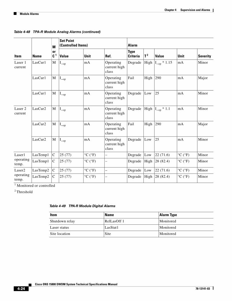
4-24Cisco ONS 15800 DWDM System Technical Specifications Manual
78-13141-03
Chapter 4 Supervision and AlarmsModule Alarms
Laser 1current
LasCur1 M I_op mA Operatingcurrent highclass
Degrade High I_op * 1.15 mA Minor
LasCur1 M I_op mA Operatingcurrent highclass
Fail High 290 mA Major
LasCur1 M I_op mA Operatingcurrent highclass
Degrade Low 25 mA Minor
Laser 2current
LasCur2 M I_op mA Operatingcurrent highclass
Degrade High I_op * 1.1 mA Minor
LasCur2 M I_op mA Operatingcurrent highclass
Fail High 290 mA Major
LasCur2 M I_op mA Operatingcurrent highclass
Degrade Low 25 mA Minor
Laser1operatingtemp.
LasTemp1 C 25 (77) °C (°F) – Degrade Low 22 (71.6) °C (°F) Minor
LasTemp1 C 25 (77) °C (°F) – Degrade High 28 (82.4) °C (°F) Minor
Laser2operatingtemp.
LasTemp2 C 25 (77) °C (°F) – Degrade Low 22 (71.6) °C (°F) Minor
LasTemp2 C 25 (77) °C (°F) – Degrade High 28 (82.4) °C (°F) Minor
1 Monitored or controlled2 Threshold
Table 4-49 TPA-R Module Digital Alarms
Item Name Alarm Type
Shutdown relay RelLasOff 1 Monitored
Laser status LasStat1 Monitored
Site location Site Monitored
Table 4-48 TPA-R Module Analog Alarms (continued)
Item Name
MorC 1
Set Point(Controlled Items) Alarm
Value Unit Ref.TypeCriteria T 2 Value Unit Severity

4-25Cisco ONS 15800 DWDM System Technical Specifications Manual
78-13141-03
Chapter 4 Supervision and AlarmsModule Alarms
Table 4-50 WCM-EM-Mxx Module Analog Alarms
Item Name
MorC1
Set Point(Controlled Items) Alarm
Value UnitTypeCriteria Threshold Value Unit Severity
Lasertemp.
LasTemp1 C T_op °C Fail Low T_op–2 °C Major
LasTemp1 C T_op °C Fail High T_op + 2 °C Major
Lasercurrent
LasCurr1 C I_op mA Degrade High I_op * 1.2 mA Minor
LasCurr1 C I_op mA Fail High I_op * 1.4 =140 mA mA Major
Laserpower
LasPwr1 C P_op mW Degrade Low P_op * 0.8 mW Minor
LasPwr1 C P_op mW Degrade High P_op * 1.2 mW Minor
Outputpower
OutPwr1 M 1 (0) mW (dBm) Degrade Low 0.79 (–1) mW (dBm) Minor
OutPwr1 M 1 (0) mW (dBm) Degrade High 1.26 (1) mW (dBm) Minor
Inputpower
InpPwr1 M – – Fail Low 0.012 (–19.2) mW (dBm) Major
InpPwr1 M — – Fail High 2.5 (3.98) mW (dBm) Major1 Monitored or controlled
Table 4-51 WCM-EM-Mxx Module Digital Alarms
Item Name Alarm Type Set Point Value Alarm Value Severity
Loss of signal LosStatus1 Controlled Off On Major
Output modulation fail ModoutStat1 Controlled On Off Major
Input modulation fail ModinStat1 Controlled On Off Major
IPO in IpoinStat1 Controlled — — Not defined
IPO out IpooutStat1 Controlled — — Not defined
OPIN OpinStat Controlled — — Not defined
Pinlow PinlowStat1 Controlled Off On Major
Shutdown relay RelLasOff1 Monitored — — —
Table 4-52 WCM-EM-Fxx Module Analog Alarms
Item Name
MorC1
Set Point(Controlled Items) Alarm
Value Unit Type, Criteria Threshold Value Unit Severity
Lasertemp.
LasTemp1 C T_op °C Fail Low T_op–2 °C Major
LasTemp1 C T_op °C Fail High T_op + 2 °C Major
Lasercurrent
LasCurr1 M I_op mA Degrade High I_op * 1.2 mA Minor
LasCurr1 M I_op mA Fail High I_op * 1.4 mA Major

4-26Cisco ONS 15800 DWDM System Technical Specifications Manual
78-13141-03
Chapter 4 Supervision and AlarmsModule Alarms
Laserpower
LasPwr1 M P_op mW Degrade Low P_op * 0.8 mW Minor
LasPwr1 M P_op mW Degrade High P_op * 1.2 mW Minor
Outputpower
OutPwr1 M Pout_op dBm Degrade Low Pout_op –1 dBm Minor
OutPwr1 M Pout_op dBm Degrade High Pout_op +1 dBm Minor
OutPwr1 M Pout_op dBm Fail Low –10 dBm Minor
Inputpower
InpPwr1 M Ip dBm Degrade High –7 dBm Major
InpPwr1 M Ip dBm Degrade Low –30 dBm Major
InpPwr1 M Ip dBm Fail Low –34 dBm Major1 Monitored or controlled
Table 4-53 WCM-EM-Fxx Module Digital Alarms
Item Name Alarm Type Set Point Value Alarm Value Severity
Output modulation fail ModoutStat1 Monitored Off On Major
Loss of signal LosStatus1 Monitored On Off Major
Wavelength locked Wavelocked Monitored Off On Major
PsTolerance Pstol Monitored Off On Major
Table 4-54 WCM-10G-Mxx Module Analog Alarms
Item Name
MorC1
Set Point(Controlled Items) Alarm
Value Unit Type Criteria Threshold Value Unit Severity
Laser temp. LasTemp1 C T_op °C Fail Low T_op–2 °C Major
LasTemp1 C T_op °C Fail High T_op + 2 °C Major
Lasercurrent
LasCurr1 M I_op mA Degrade High I_op * 1.2 mA Minor
LasCurr1 M I_op mA Fail High I_op * 1.4 mA Major
Laserpower
LasPwr1 M P_op mW Degrade Low P_op * 0.8 mW Minor
LasPwr1 M P_op mW Degrade High P_op * 1.1 mW Minor
Outputpower
OutPwr1 M 0 mW (dBm) Degrade Low 0.79(–1) mW (dBm) Minor
OutPwr1 M 0 mW (dBm) Degrade High 1.26 (1) mW (dBm) Minor
Inputpower
InpPwr1 M Ip dBm Degrade Low –12 dBm Minor
InpPwr1 M Ip dBm Fail Low –15 dBm Major1 Monitored or controlled
Table 4-52 WCM-EM-Fxx Module Analog Alarms (continued)
Item Name
MorC1
Set Point(Controlled Items) Alarm
Value Unit Type, Criteria Threshold Value Unit Severity
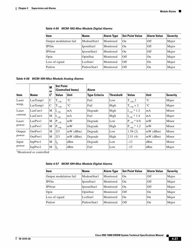
4-27Cisco ONS 15800 DWDM System Technical Specifications Manual
78-13141-03
Chapter 4 Supervision and AlarmsModule Alarms
Table 4-55 WCM-10G-Mxx Module Digital Alarms
Item Name Alarm Type Set Point Value Alarm Value Severity
Output modulation fail ModoutStat1 Monitored On Off Major
IPOin IpoinStat1 Monitored On Off Major
IPOout IpooutStat1 Monitored On Off Major
Opin OpinStat Monitored Off On Major
Loss of signal LosStat1 Monitored Off On Major
Pinlow PinlowStat1 Monitored Off On Major
Table 4-56 WCM-10H-Mxx Module Analog Alarms
Item Name
MorC1
Set Point(Controlled Items) Alarm
Value Unit Type Criteria Threshold Value Unit Severity
Lasertemp.
LasTemp1 C T_op °C Fail Low T_op–2 °C Major
LasTemp1 C T_op °C Fail High T_op + 2 °C Major
Lasercurrent
LasCurr1 M I_op mA Degrade High I_op * 1.2 mA Minor
LasCurr1 M I_op mA Fail High I_op * 1.4 mA Major
Laserpower
LasPwr1 M P_op mW Degrade Low P_op * 0.8 mW Minor
LasPwr1 M P_op mW Degrade High P_op * 1.2 mW Minor
Outputpower
OutPwr1 M 2/3 mW (dBm) Degrade Low 1.58 (2) mW (dBm) Minor
OutPwr1 M 2/3 mW (dBm) Degrade High 2.51 (4) mW (dBm) Minor
Inputpower
InpPwr1 M Ip dBm Degrade Low –12 dBm Minor
InpPwr1 M Ip dBm Fail Low –15 dBm Major1Monitored or controlled
Table 4-57 WCM-10H-Mxx Module Digital Alarms
Item Name Alarm Type Set Point Value Alarm Value Severity
Output modulation fail ModoutStat1 Monitored On Off Major
IPOin IpoinStat1 Monitored On Off Major
IPOout IpooutStat1 Monitored On Off Major
Opin OpinStat Monitored Off On Major
Loss of signal LosStat1 Monitored On On Major
Pinlow PinlowStat1 Monitored Off On Major
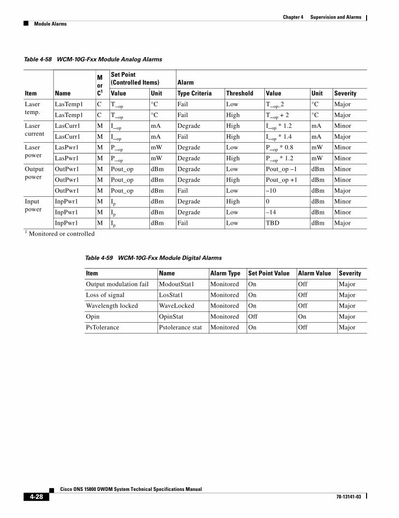
4-28Cisco ONS 15800 DWDM System Technical Specifications Manual
78-13141-03
Chapter 4 Supervision and AlarmsModule Alarms
Table 4-58 WCM-10G-Fxx Module Analog Alarms
Item Name
MorC1
Set Point(Controlled Items) Alarm
Value Unit Type Criteria Threshold Value Unit Severity
Lasertemp.
LasTemp1 C T_op °C Fail Low T_op–2 °C Major
LasTemp1 C T_op °C Fail High T_op + 2 °C Major
Lasercurrent
LasCurr1 M I_op mA Degrade High I_op * 1.2 mA Minor
LasCurr1 M I_op mA Fail High I_op * 1.4 mA Major
Laserpower
LasPwr1 M P_op mW Degrade Low P_op * 0.8 mW Minor
LasPwr1 M P_op mW Degrade High P_op * 1.2 mW Minor
Outputpower
OutPwr1 M Pout_op dBm Degrade Low Pout_op –1 dBm Minor
OutPwr1 M Pout_op dBm Degrade High Pout_op +1 dBm Minor
OutPwr1 M Pout_op dBm Fail Low –10 dBm Major
Inputpower
InpPwr1 M Ip dBm Degrade High 0 dBm Minor
InpPwr1 M Ip dBm Degrade Low –14 dBm Minor
InpPwr1 M Ip dBm Fail Low TBD dBm Major1 Monitored or controlled
Table 4-59 WCM-10G-Fxx Module Digital Alarms
Item Name Alarm Type Set Point Value Alarm Value Severity
Output modulation fail ModoutStat1 Monitored On Off Major
Loss of signal LosStat1 Monitored On Off Major
Wavelength locked WaveLocked Monitored On Off Major
Opin OpinStat Monitored Off On Major
PsTolerance Pstolerance stat Monitored On Off Major
C H A P T E R
5-1Cisco ONS 15800 DWDM System Technical Specifications Manual
78-13141-03
5Engineering Specifications
This chapter covers the mechanical, electrical, environmental, reliability, optical, safety, access, and marking specifications of the ONS 15800 system. Additional information about modules is in Chapter 3, “Module Specifications.”
MechanicalThis section contains mechanical descriptions of the ONS 15800 system: Physical Layout, Optical Subrack, Module Insertion, and Dimensions.
Physical LayoutEvery site of the ONS 15800 system consists of one or more bays. Each bay contains at least one subrack and is configured according to site requirements. ONS 15800 modules are installed in the subracks and share power, signal, and monitoring information over the subrack interface. A sample bay configuration is shown in Figure 5-1.

5-2Cisco ONS 15800 DWDM System Technical Specifications Manual
78-13141-03
Chapter 5 Engineering SpecificationsMechanical
Figure 5-1 Sample Bay Configuration of Modules in Subracks
The example in Figure 5-1, a terminal site, contains three optical subracks that house optical modules. The figure also contains one Optical Subrack–Multiplexer (OSR-MUX) to house passive multiplexer modules. Dispersion Compensating Unit–Blue band (DCU-B) and Dispersion Compensating Unit–Red band (DCU-R) modules are not used in this example. If they are needed in the site configuration, they are installed separately in an Optical Subrack–Dispersion Compensating Unit (OSR-DCU) as shown in Figure 5-4.
TP
A-R
TP
A-B
PR
E-L
24W
D-R
C06
-W
EO
I-W
LSM
-W
CM
P-W
or
CM
P-W
-2E BA
T
WC
M-0
9 WCM-11
RX
T
WCM-11
8WM-B 24WM-R
C06
-W
IOC
-WS
CF
BA
TS
CF
SC
F
WC
M-1
0W
CM
-11
WC
M-1
2W
CM
-13
WC
M-1
4W
CM
-15
WC
M-1
6W
CM
-17
WC
M-1
8W
CM
-19
WC
M-2
0W
CM
-21
WC
M-2
2W
CM
-23
WC
M-2
4
RX
TR
XT
RX
TR
XT
RX
TR
XT
RX
TR
XT
RX
TR
XT
RX
TR
XT
RX
TR
XT
RX
TB
AT
SC
F
8WD
-B
C06
-W
6492
5
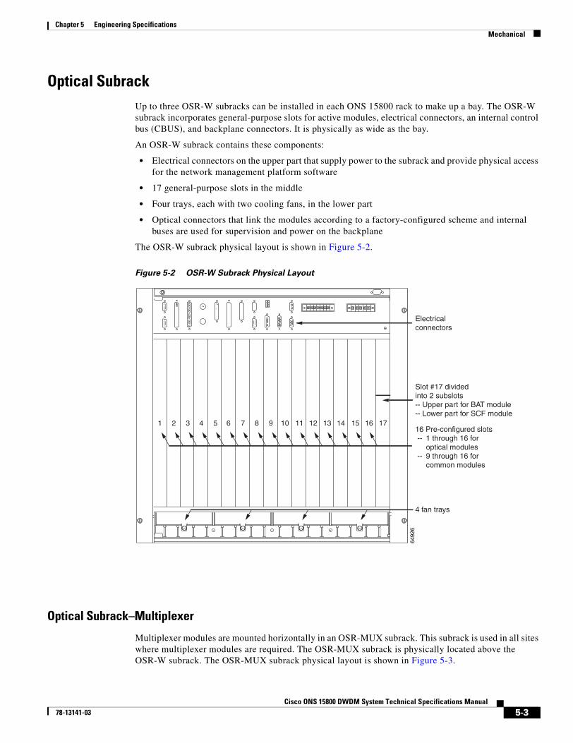
5-3Cisco ONS 15800 DWDM System Technical Specifications Manual
78-13141-03
Chapter 5 Engineering SpecificationsMechanical
Optical SubrackUp to three OSR-W subracks can be installed in each ONS 15800 rack to make up a bay. The OSR-W subrack incorporates general-purpose slots for active modules, electrical connectors, an internal control bus (CBUS), and backplane connectors. It is physically as wide as the bay.
An OSR-W subrack contains these components:
• Electrical connectors on the upper part that supply power to the subrack and provide physical access for the network management platform software
• 17 general-purpose slots in the middle
• Four trays, each with two cooling fans, in the lower part
• Optical connectors that link the modules according to a factory-configured scheme and internal buses are used for supervision and power on the backplane
The OSR-W subrack physical layout is shown in Figure 5-2.
Figure 5-2 OSR-W Subrack Physical Layout
Optical Subrack–Multiplexer
Multiplexer modules are mounted horizontally in an OSR-MUX subrack. This subrack is used in all sites where multiplexer modules are required. The OSR-MUX subrack is physically located above the OSR-W subrack. The OSR-MUX subrack physical layout is shown in Figure 5-3.
1 2 3 4 5 6 7 8 9 10 11 12 13 14 15 16 17
12
34
56
Electricalconnectors
Slot #17 divided into 2 subslots-- Upper part for BAT module-- Lower part for SCF module
16 Pre-configured slots -- 1 through 16 for
optical modules -- 9 through 16 for
common modules
4 fan trays
6492
6

5-4Cisco ONS 15800 DWDM System Technical Specifications Manual
78-13141-03
Chapter 5 Engineering SpecificationsMechanical
Figure 5-3 OSR-MUX Subrack Physical Layout
In this example, the three slots accommodate one 24-Channel Wavelength Multiplexer–Red band (24WM-R) and at least one (possibly two) 8-Channel Wavelength Multiplexer–Blue band (8WM-B) modules. The OSR-MUX subrack has no backplane, so optical fiber connections are made directly to the back of the modules using SC connectors.
Optical Subrack–Dispersion Compensating Unit
Dispersion Compensating Unit modules are mounted horizontally in an OSR-DCU subrack, shown in Figure 5-4.
Figure 5-4 OSR-DCU Subrack Physical Layout
Each OSR-DCU subrack accommodates two DCU modules. The subrack has no backplane, so the input and output connections are made directly to the back of the DCU modules with E-2000 connectors.
Module InsertionEach module is positioned in its subrack by using extractor handles mounted on the module. It is secured in place with thumbscrews. When a module is fully inserted in a subrack, it automatically engages the backplane electrical connectors.
DimensionsModule dimensions are listed in Chapter 3, “Module Specifications.” Subrack dimensions are listed in Table 5-1.
2 slots for 8WM-B 1 slot for 24WM-R
8WM-B 24WM-R8WM-B
6492
7
DCUDCU
2 slots for DCU modules
6492
4
Table 5-1 ONS 15800 Subrack Dimensions
Subrack Height Width1 Depth Weight
OSR-W subrack 577 mm (22.72 in.) 592 mm (23.31 in.) 370 mm (14.57 in.) 14.00 kg (30.86 lb)
OSR-MUX subrack 45 mm (1.77 in.) 592 mm (23.31 in.) 370 mm (14.57 in.) 2.30 kg (5.07 lb)

5-5Cisco ONS 15800 DWDM System Technical Specifications Manual
78-13141-03
Chapter 5 Engineering SpecificationsElectrical
ElectricalThis section covers ONS 15800 system power management and grounding.
Power SupplyEach OSR-W subrack is equipped with a BAT module that provides power to the system. This module conditions and filters line power. It contains the following independent units:
• One frame (BATFRM), the mechanical framing structure inserted in the OSR-W subrack
• Two sub-bat units (BATMOD), each mounted into and extractable from the BATFRM
The filtered output of the two BATMOD modules is paralleled together on the BATFRM to provide redundant and independent 48-VDC power supplies (BAT1 and BAT2). The electrical characteristics of the BATMOD units are shown with the BAT module specifications in Chapter 3, “Module Specifications.”
GroundingTable 5-2 lists the grounds provided on the ONS 15800 system.
Power ConsumptionThe maximum power consumption for each module from the station DC supply is shown in Chapter 3, “Module Specifications.”
EnvironmentalTable 5-3 shows environmental characteristics for the ONS 15800 system.
OSR-DCU subrack 45 mm (1.77 in.) 592 mm (23.31 in.) 370 mm (14.57 in.) 4.20 Kg (9.26 lb)1Width between mounting holes
Table 5-1 ONS 15800 Subrack Dimensions (continued)
Subrack Height Width1 Depth Weight
Table 5-2 ONS 15800 Ground Characteristics
Ground Characteristics
GROUND (7-pole strip) This is the ground termination of all separate grounds in the subrack. It is the only point in the subrack for interconnection of grounds.
POWER (5-pole strip) This is the power and ground connector. It provides power and alternate grounding for the system.

5-6Cisco ONS 15800 DWDM System Technical Specifications Manual
78-13141-03
Chapter 5 Engineering SpecificationsReliability
ReliabilityONS 15800 system reliability predictions are based on the Part Stress Count Analysis according to the British Telecom HRD4 model (Handbook of Reliability Data, Issue 4, 1987). For devices that are hard to classify or where HRD4 data is not appropriate, the failure rates are derived from the following sources:
• The model in the Spring 1993 issue of HRD5 issued in conjunction with Italtel and Centre National d'Etudes des Telecommunications (CNET)
• The 1990 Telcordia guide
• Manufacturer reliability reports
Table 5-4 shows ONS 15800 module data as rated in mean time between failures (MTBF) and failures in time (FITs).
Table 5-3 ONS 15800 System Environmental Characteristics
Item Min. Max. Unit
Normal Operations:
Operating temperature range 5°C (40°F) 40°C(104°F) °C (°F)
Operating relative humidity range 5% 85% %
Short Term Operations (less than 96 hours continuously):
Operating temperature range –5°C (22°F) 50°C(122°F) °C (°F)
Operating relative humidity range 5% 95% %
Storage and Transportation (with equipment packaged):
Temperature range –40°C (–40°F) 70°C (158°F) °C (°F)
Relative humidity range 5% 95% %
Table 5-4 Reliability Data for ONS 15800 Modules
Module MTBF (years) FIT
1-Channel Pass-Through (1PT-W) module
To be determined To be determined
24WD-LLR module 26 4393
24WD-R module 28 4103
24WM-R module 69 1650
8WD-B module 36 3113
8WM-B module 163 698
ADA module 26.5 4308
BAT module 252 453
BBA module 30 3800
BBA-10G module 26.9 4249
CMP-W module 32.6 3500

5-7Cisco ONS 15800 DWDM System Technical Specifications Manual
78-13141-03
Chapter 5 Engineering SpecificationsOptical
OpticalThis section addresses ONS 15800 system optical connectors and safety.
CMP-W-2E module 32.6 3500
DCU-B module 570.8 200
DCU-R module 570.8 200
EOI-W module 61.7 1850
IOC-W module 98 1169
LEM-10G-Fxx module 16 7134
LEM-10G-Mxx module 19.7 5800
LEM-10H-Mxx module 18 6237
LEM-EM-Fxx module 16 7148
LEM-EM-Mxx module 21.3 5352
LSM-W module 18.6 6128
OADM-P4-R1 module 25.6 4461
OADM-P4-R3 module 25.6 4461
PRE-L module 27.1 4210
RBA module 25.1 4549
RBA-10G module 26.9 4249
RBU module 42 2720
RXT-10G-F module 17 6734
RXT-10G-M module 19.7 5800
RXT-DM-F module 25 4554
RXT-DM-M module 21.7 5252
SCF module 52.9 2157
TPA-B module 26.9 4249
TPA-R module 24.5 4661
WCM-10G-Fxx module 16 7134
WCM-10G-Mxx module 13.3 8600
WCM-10H-Mxx module 18 6237
WCM-EM-Fxx module 16 7148
WCM-EM-Mxx module 21.3 5352
Table 5-4 Reliability Data for ONS 15800 Modules (continued)
Module MTBF (years) FIT
5-8Cisco ONS 15800 DWDM System Technical Specifications Manual
78-13141-03
Chapter 5 Engineering SpecificationsSafety
Optical ConnectorsModule front fiber connectors are SC connectors. All fiber connectors are angled downward as a safety measure. The connectors have mechanical shutters to protect personnel against exposure to potentially harmful laser light.
Module connectors to the backplane are Diamond E-2000 connectors. These fiber optic connectors have automatic closures to permit easy mating and demating.
Optical Safety and ProtectionThe ONS 15800 system complies with the requirements and specific guidance of 21cfr1040.10 regarding the safety features of communication systems that employ optical signals. 21cfr1040.10 classifies these types of communication systems using the following classes:
• Hazard level—The potential hazard at any accessible location within an optical fiber communication system. It is based upon the level of optical radiation that could become accessible in reasonably foreseeable circumstances.
• Location access—The location where the system is installed (regarding system accessibility by qualified or unqualified people).
The maximum optical power available in the ONS 15800 system is about 120 mW in the 1260-nm to 1605-nm wavelength range, which corresponds to Laser Class IIIb standards. Access to the location containing Class IIIb products must be restricted to qualified and properly trained people. To prevent Class IIIb hazards, the ONS 15800 system provides an automatic power reduction function. In less than one second, the system radiation is decreased to Class IIIa levels when the fiber is disrupted or the cable is disconnected. This reduction is in line with IEC-60825. In addition, all ONS 15800 optical amplifiers incorporate an automatic safety shutdown mechanism that turns off the laser when the signal is lost. This feature can be overridden manually for testing and repair.
SafetyThe ONS 15800 system is compliant with IEC-60825 automatic shutdown and safety labeling requirements. The system is also compliant with UL 1950. The system conforms to the applicable Network Equipment-Building System (NEBS) Level 3 criteria in Telcordia GR-63, Issue 1, and GR-1089, Issue 2, as follows:
Note The ONS 15800 system NEBS Level 3 compliance does not include the External Orderwire Interface module (EOI-W).
GR-1089:
• Section 2—Electrostatic Discharge
• Section 3—Electromagnetic Interference
• Section 4—Lightning and AC Power Fault
• Section 7—Electrical Safety
• Section 9—Bonding and Grounding

5-9Cisco ONS 15800 DWDM System Technical Specifications Manual
78-13141-03
Chapter 5 Engineering SpecificationsElectromagnetic Compatibility
GR-63:
• Section 4.1—Thermal
• Section 4.2—Fire Resistance
• Section 4.3—Handling and Transportation
• Section 4.4—Earthquake, Office Vibration, and Transportation Vibration
• Section 4.5—Airborne Contaminants
• Section 4.6 and 4.7—Acoustics/Illumination
Electromagnetic CompatibilityThe ONS 15800 system is compliant with GR-1089 (Section 3) and FCC Part 15 specifications for electromagnetic compatibility.
AccessONS 15800 equipment is designed for front and rear access. Optical fiber patch cords are connected to the amplifier module front panels. Electrical connections are made on the front of the backplane in the space above the system modules. Test points, switches, and LED indicators are located on the front panels of appropriate modules. However, when it is installed, ONS 15800 equipment needs two feet (approximately 600 mm) of clearance in front for module installation and two feet (approximately 600 mm) of clearance behind for fiber management and fan filter maintenance.
MarkingAll ONS 15800 equipment containing a laser source is classified according to the optical signal emitted. The ONS 15800 equipment is labeled according to American National Standards Institute (ANSI) code requirements. Labels contain such things as hazard symbols and warnings.

5-10Cisco ONS 15800 DWDM System Technical Specifications Manual
78-13141-03
Chapter 5 Engineering SpecificationsMarking