Embed Size (px)
Citation preview

15.11.2017

K-PPR-G-TK-ENG/15.11.2017

4
Kalde is leading pipes and fittings manufactoring company with over 40 years experience in designing and innovating highest
quality products and integrated solutions for its customers globally.
The company is located in Istanbul, Turkey, where two continents, Asia and Europe meet.
Our strategic location with respect to Europe, Asia and Africa gives us unique advantages to serve our business partners
and clients with our reliable supply chain capabilities and to compete successfully in global markets. We already export our
products to more than 40 countries all around the world including Germany, Hungary, Romania, Austria, Greece, Bulgaria,
Russia, Ukraine, Egypt, Syria, Lebanon...
Kalde has 300,000 square meters open storage area and 100,000 square meters production area complete with design,
product development and quality control facilities.
We manufacture a broad line of products covering PP pipes, PP fittings, Al-pex - PE-rt pipes, screw fittings, press fittings,
PE-x pipes, manifolds and radiators. We also have several internationally accredited certifications from respectable master
institutes like SKZ-Germany and AENOR-Spain. Furthermore, our management quality is certified by ISO 9001:2008.
We pride ourselves on our high quality products and best business practices...
Our vision is to deliver an expanding range of highest quality products and solutions to our customers through continuous
research and innovation. We aim to develop long-term partnerships with our customers and suppliers.
We create integrated solutions through teamwork within the company as well as working closely with customers and partners.
Through dedicated, market-focused business teams with 2000 professional staff and strong management team, we drive
responsive solutions and deliver value to our business partners and customers worldwide.
That‘s why Kalde is the “First Choice” of hundreds of customers globally.
Kalde Value Proposition
Kalde was founded in 1977 by four young engineers who were dedicated to provide the best service to their customers.
That spirit is still alive today and remains the focus of our missions.
Kalde’s Success is a Result of Many Factors.• High quality products.
• Use of best practices.
• Products that meet your unique requirements.
• Products that are proven.
• Total client satisfaction.
• Long-term successful relationships with each client.
• A committed team of 2000 people.
Why Kalde?

5
Kalde PP-r Tubes and Fittings for Hot & Cold Water and Heating Installation Systems ........... 6
• Applied Norms ..............................................................................................................................................6
• Raw material: Polypropylene Random Copolimer (PP-r) ..........................................................................7
• Thermal Expansion in PP-r Tubes ..............................................................................................................10
• Hydrostatic Pressure Performance ............................................................................................................12
• Chemical Resistance ....................................................................................................................................13
• Polypropylene Tubes with Aluminum Foil .................................................................................................16
• Thermal Expansion in PP-r Tubes with Aluminum Foil ............................................................................18
• Polypropylene Pipes with Fiberglass .........................................................................................................19
• Thermal Expansion in Polypropylene Pipes with Fiberglass ..................................................................21
• Mounting and Installation ...........................................................................................................................22
• Removing Expansions from Installation ....................................................................................................23
• Calculation of Elongation ...........................................................................................................................24
• Support Intervals ..........................................................................................................................................25
• Welding Technique ....................................................................................................................................26
• Insulation of Pipes ........................................................................................................................................28
• Protection of Hot Water System Against Heat Loss .................................................................................29
• Thermal Insulation of Warm Water Pipes ..................................................................................................29
• Calculation Of Economic Pipe Insulation Material Thickness.................................................................30
• Several Thermal Insulation Materials and Their Properties .....................................................................30
• Pressure Losses ............................................................................................................................................31
• Pressure loss in straight pipes ....................................................................................................................31
• Pipe Laying ...................................................................................................................................................32
• Test Procedure ..............................................................................................................................................32
• Points to Pay Attention to When Installing Polypropylene Pipes and Fittings ......................................32
PP-r Products .......................................................................................................................... 33
• Polypropylene Tubes ...................................................................................................................................34
• Polypropylene Fittings .................................................................................................................................37
• Accessories ...................................................................................................................................................55
• Kalde Warranty ............................................................................................................................................57
Contents

6
• Applied Norms
DIN 8077 Polypropylene (PP) pipes’ dimensions
DIN 8078 Polypropylene (PP) pipes’ general quality requirements and testing
DIN 16962 Pipe joints and elements for polypropylene (PP) pressure pipelines,
(6-9) types 1 and 2; injection moulded elbows for socket-welding, dimensions
DIN 16962 Pipe joints and components of polypropylene (PP) for pipes under pressure, -
Part 5: General quality requirements, testing
DIN 1988 Drinking water line installation
DIN 4109 Sound insulation in building construction
DVS 2207 Welding regulations for plastic pipes
(11)
DVS 2208.1 Machines and devices for welding thermoplastic pipes
DIN 10226-1 Pipe threads where pressure tight joints are made on the thereads –
Part 1: Taper external threads and paralel internal threads
- Dimension, tolerances and designation
DIN 16928 Pipe connections and components - Pipes of thermoplastic materials;
pipe joints, elements for pipes, laying; general directions
EN ISO 15874 Plastics piping systems for hot and cold water installations – polypropylene;
Part 1: General, Part 2: Pipe, Part 3: Fittings, Part 5: Fitnes for purpose of the systems,
Part 7: Guidance for the assessment of conformity
Kalde PP-r Tubes and Fittings for Hot & Cold Water and Heating Installation Systems

7
Properties Testing Methods Unit Values
Tensile stres at yield (23 °C)
At 50 mm/min ISO 527-1,-2N/mm2 24
Tensile strain at yield At 50 mm/min % 10
Flexural modulus at 23 °C ISO 527 N/ mm2 800
Charpy impact strength (notched)
at 23 °C
at 0 °CISO 179/1eA
kJ/ m2
kJ/ m2
22
4,5
Charpy impact strength (unnotched) (0 C °) ISO 179 Joule No break
Hardness (shore D) ISO 868 60
• Raw Material: Polypropylene Random Copolimer (PP-r)
Polypropylene Random Copolimer (PP-r) is widely used in hot water, floor- and radiator heating systems as well as in industrial
liquid distribution systems. Most commonly, this material can be found in drinking water installations.
Kalde pipes are produced using solely PP-r. PP-r has several advantages over other materials: long duration, better flexibility,
high resistance to pressure and heat, high molecular weight, low MFR, high acoustic and thermal insulation.
PP-r is suitable for DIN 8078 and EN ISO 15874-1 standards.
The metal inserts used in the polypropylene fittings increase the reliability of the products. Kalde’s experience in brass fittings
for more than 35 years results in high quality fittings with very reliable metal inserts.
Physical and Thermal Properties
Mechanical Properties
Properties Testing Methods Unit Values
Density, at 23 °C ISO 1183 g/cm3 0,9
Melt flow index (MFI) 230 °C/2, 16 kg ISO 1133 g/10 min 0,3
Thermal conductivity at 23 °C DIN 52612-1 W/m.K 0,23
Coefficient of linear expansion K-1
average between 0 °C up to 110 °CDIN 53712 K-1 1,5 x10⁻⁴
Surface Resistance (ohm) DIN IEC 60093 Ω >1012
Deflection temperature under load
1,8 N/mm2
0,45 N/mm2ISO 75A-1, -2
ISO 75B-1, -2
°C
°C
49
70
VICAT softening point
(1 kg)
(5 kg)
ASTM D 1525
ISO 306
DIN 53460
°C
°C
130
70
Melting point DSC °C 146
OIT (oxydation induction time 200 °C ) EN 728 (≥20) >25
8
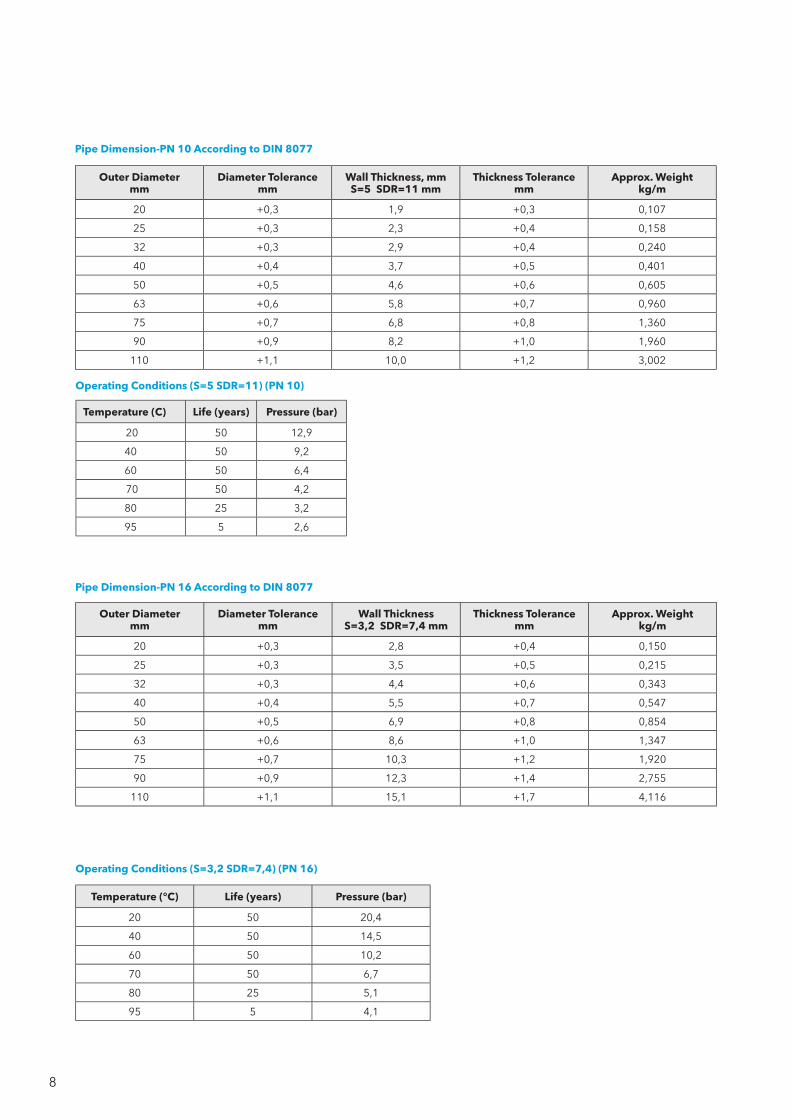
Operating Conditions (S=3,2 SDR=7,4) (PN 16)
Temperature ( °C) Life (years) Pressure (bar)
20 50 20,4
40 50 14,5
60 50 10,2
70 50 6,7
80 25 5,1
95 5 4,1
Temperature (C ) Life (years) Pressure (bar)
20 50 12,9
40 50 9,2
60 50 6,4
70 50 4,2
80 25 3,2
95 5 2,6
Operating Conditions (S=5 SDR=11) (PN 10)
Outer Diameter mm
Diameter Tolerance mm
Wall Thickness, mm S=5 SDR=11 mm
Thickness Tolerance mm
Approx. Weight kg/m
20 +0,3 1,9 +0,3 0,107
25 +0,3 2,3 +0,4 0,158
32 +0,3 2,9 +0,4 0,240
40 +0,4 3,7 +0,5 0,401
50 +0,5 4,6 +0,6 0,605
63 +0,6 5,8 +0,7 0,960
75 +0,7 6,8 +0,8 1,360
90 +0,9 8,2 +1,0 1,960
110 +1,1 10,0 +1,2 3,002
Pipe Dimension-PN 10 According to DIN 8077
Pipe Dimension-PN 16 According to DIN 8077
Outer Diameter mm
Diameter Tolerance mm
Wall Thickness S=3,2 SDR=7,4 mm
Thickness Tolerance mm
Approx. Weight kg/m
20 +0,3 2,8 +0,4 0,150
25 +0,3 3,5 +0,5 0,215
32 +0,3 4,4 +0,6 0,343
40 +0,4 5,5 +0,7 0,547
50 +0,5 6,9 +0,8 0,854
63 +0,6 8,6 +1,0 1,347
75 +0,7 10,3 +1,2 1,920
90 +0,9 12,3 +1,4 2,755
110 +1,1 15,1 +1,7 4,116
9
Nominal Diameter
(Ød) mmWall Thickness (s)
mmThickness
Tolerance mm
20 4,1 +0,6
25 5,1 +0,7
32 6,5 +0,8
40 8,1 +1,0
50 10,1 +1,2
63 12,7 +1,4
75 15,1 +1,7
90 18,1 +2,0
110 22,1 +2,3
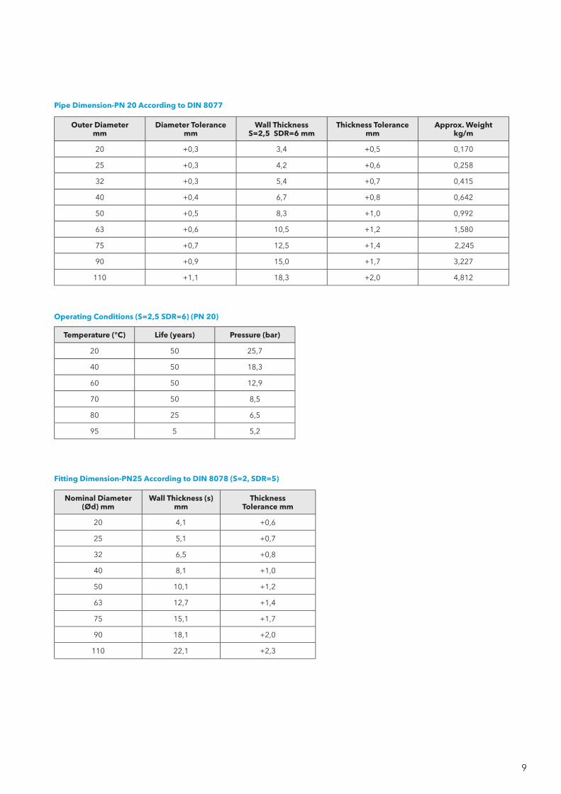
Fitting Dimension-PN25 According to DIN 8078 (S=2, SDR=5)
Outer Diameter mm
Diameter Tolerance mm
Wall Thickness S=2,5 SDR=6 mm
Thickness Tolerance mm
Approx. Weight kg/m
20 +0,3 3,4 +0,5 0,170
25 +0,3 4,2 +0,6 0,258
32 +0,3 5,4 +0,7 0,415
40 +0,4 6,7 +0,8 0,642
50 +0,5 8,3 +1,0 0,992
63 +0,6 10,5 +1,2 1,580
75 +0,7 12,5 +1,4 2,245
90 +0,9 15,0 +1,7 3,227
110 +1,1 18,3 +2,0 4,812
Pipe Dimension-PN 20 According to DIN 8077
Operating Conditions (S=2,5 SDR=6) (PN 20)
Temperature (°C ) Life (years) Pressure (bar)
20 50 25,7
40 50 18,3
60 50 12,9
70 50 8,5
80 25 6,5
95 5 5,2

10
• Thermal Expansion in PP-r Tubes
Pipe length
(M)
Temperature variation ∆T in K
1 5 10 20 30 40 50 60 70 80
Linear expansion ∆L (mm)
1.0 0.15 0.75 1.50 3.00 4.50 6.00 7.50 9.00 10.50 12.00
2.0 0.30 1.50 3.00 6.00 9.00 12.00 15.00 18.00 21.00 24.00
3.0 0.45 2.25 4.50 9.00 13.50 18.00 22.50 27.00 31.50 36.00
4.0 0.60 3.00 6.00 12.00 18.00 24.00 30.00 36.00 42.00 48.00
5.0 0.75 3.75 7.50 15.00 22.50 30.00 37.50 45.00 52.50 60.00
6.0 0.90 4.50 9.00 18.00 27.00 36.00 45.00 54.00 63.00 72.00
7.0 1.05 5.25 10.50 21.00 31.50 42.00 52.50 63.00 73.50 84.00
8.0 1.20 6.00 12.00 24.00 36.00 48.00 60.00 72.00 84.00 96.00
9.0 1.35 6.75 13.50 27.00 40.50 54.00 67.50 81.00 94.50 108.00
10.0 1.50 7.50 15.00 30.00 45.00 60.00 75.00 90.00 105.00 120.00
Note: When the water temperature circulating in the pipe is higher than the environmental temperature, the result will be an elongation. But if the water temperature circulating in the pipe is lower than the environmental temperature, the result will be a shortage.
Thermal Expansion of the Kalde PP-r Pipe
l
The polypropylene pipes have an expansion coefficient that is much higher than the metal pipes. It is critical to take this
characteristic into consideration during installations.
Calculation of thermal expansion is as follows: ∆L = L * ∆T * l
where
∆T = The difference between environmental temperature and water temperature in Kelvin degrees (K) or Celsius (°C).
∆L = Variation of length in mm.
L = Initial length of the pipe in m.
l = Coefficient of linear thermal expansion. The value of l is 1,5 * 10-4 (K-1) for PP-r tubes.

11
• Operating Life According to DIN 8077 (SF=1.5 PP-r 80)
Temperature
°C
OperationLife
(Year)
Series (S)
20 16 12,5 8,3 5 3,2 2,5 2
Standard Dimention Rate (SDR)
41
PN2,5
33
PN3,2
26
PN4
17,6
PN6
11
PN10
7,4
PN16
6
PN20
5
PN25
Pressure (bar)
20
1 5 10 25 50100
3,73,53,43,33,23,1
4,74,44,34,14,03,9
5,95,65,45,25,15,0
9,08,48,27,97,77,5
15,014,113,713,212,912,5
23,722,321,721,020,419,9
29,928,127,426,425,725,0
37,735,434,533,332,431,5
30
1 5 10 25 50100
3,23,02,92,82,72,6
4,03,73,63,53,43,3
5,04,74,64,44,34,2
7,67,27,06,76,56,3
12,711,911,611,210,910,6
20,218,918,417,717,216,8
25,423,823,222,321,721,1
32,030,029,228,127,426,6
40
1 5 10 25 50100
2,72,52,42,32,32,2
3,43,23,12,92,92,8
4,34,03,93,73,63,5
6,56,05,95,65,55,3
10,810,19,89,49,28,9
17,116,015,515,014,514,1
21,620,219,618,818,317,8
27,225,424,723,723,122,4
50
1 5 10 25 50100
2,32,12,02,01,91,8
2,82,72,62,52,42,3
3,63,43,33,13,02,9
5,55,14,94,74,64,5
9,18,58,27,97,77,5
14,513,513,112,612,211,8
18,217,016,515,915,414,9
23,021,420,820,019,418,8
60
1 5 10 25 50
1,91,81,71,61,6
2,42,22,22,12,0
3,02,82,72,62,5
4,64,34,14,03,8
7,77,16,96,66,4
12,211,311,010,510,2
15,414,313,913,312,9
19,418,017,516,716,2
70
15
102550
1,61,51,41,21,0
2,01,91,81,51,3
2,52,42,32,01,7
3,93,63,53,02,5
6,56,05,85,04,2
10,39,59,28,06,7
12,912,011,610,08,5
16,315,114,612,710,7
80
1 5 10 25
1,31,21,00,8
1,71,51,21,0
2,11,91,61,2
3,22,92,41,9
5,44,84,03,2
8,67,66,45,1
10,89,68,16,5
13,712,110,28,1
95 1 5
(10)1
0,90,6
(0,5)
1,20,8
(0,6)
1,51,0
(0,8)
2,31,5
(1,3)
3,82,6
(2,2)
6,14,1
(3,4)
7,65,2
(4,3)
9,66,5
(5,5)

12
Hydrostatic pressure is calculated according to the below formula:
P = Internal pressure, MPa.
de = Outside diameter of the pipe, mm.
emin = Minimum wall thickness of the pipe, mm.
s = Hydrostatic stress, MPa.
1MPa = 10 bar = 14.5 Psi.
P=2 *emin *s
de-emin
• Hydrostatic Pressure Performance

13
Sample:
Usage time of the pipe : 50 years
Operating temperature : 20°C
Outside diameter of pipe : Ø32
Wall thickness of pipe : 5,4 mm
Hydrostatic stress : 9.5 MPa
Maksimum operating pressure
P = (20 x 5,4 x 9,5) / (32 - 5,4)
P = 1026 / 26,6
P = 38,57 bar
This result shows the maximum resistance in a certain time, in order to find the maximum pressure,
the value the maximum resistance should be divided by safety factor (for example, Kalde pipe safety factor is SF:1,5)
Pmax = Pmax / SF
Pmax = 38,57 / 1.5
Pmax = 25,7 bar (see page 9)
• Chemical Resistance
Polypropylene has a very high chemical resistance as a polymer.
The following table lists the chemical resistance of PP-r pipe and fittings according to ISO 10358.
Since chemical resistance depends on factors such as chemical composition, concentration and
temperature, the table below gives chemical resistance for three different temperatures and
different concentrations.
The below abbreviations are used in the table:
W.s. water solution
S.s. saturated solution
R resistant
L limited resistant
NR nonresistant
- insufficient information
Compatibilities reported on the table are valid for PP-r not submitted to mechanical stresses.
Application class
Design temperature,
TD °C
Time at TD years
Tmax °C
Time at Tmax years
Tmal °C
Time at Tmal h
Typical field of application
1 60 49 80 1 95 100 Hot water supply (60°C)
2 70 49 80 1 95 100 Hot water supply (70°C)
Classification of Service Conditions

14
Chemical Resistance of Polypropylene, at 20, 60 and 100°C (ISO 10358)
Chemical or Product ConcentrationTemperature °C
20 60 100
Acetic acid Up to 40 % R R -
Acetic acid 50 % R R L
Acetic acid, glacial > 96 % S L NR
Acetic anhydride 100 % R - -
Acetone 100 % R R -
Aceptophenone 100 % R L -
Acrylonitrile 100 % R - -
Air R R R
Allyl alcohol 100 % R R -
Almond oil R - -
Alum W.s R R -
Ammonia, aqueous S.s R R -
Ammonia, dry gas 100 % R - -
Ammonia, liquid 100 % R - -
Ammonium acetate S.s R R -
Ammonium chloride S.s R R -
Ammonium fluoride Up to 20% R R -
Ammonium hydrogen carbonate S.s R R -
Ammonium metaphosphate S.s R R R
Ammonium nitrate S.s R R R
Ammonium persulphate S.s R R -
Ammonium phosphate S.s R - -
Ammonium sulphate S.s R R R
Ammonium sulphide S.s R R -
Amyl acetate 100 % L - -
Amyl alcohol 100 % R R R
Aniline 100 % R R -
Apple juice R - -
Aqua regia HCI/HNO3=3/1 NR NR NR
Barium bromide S.s R R R
Barium carbonate S.s R R R
Barium chloride S.s R R R
Barium hydroxide S.s R R R
Barium sulphide S.s R R R
Beer R R -
Benzene 100 % L NR NR
Benzoic acid S.s R R -
Benzyl alcohol 100 % R L -
Borax W.s R R -
Boric acid S.s R - -
Boron trifluoride S.s R - -
Bormine, gas 100 % NR NR NR
Bromine, liquid 100 % NR NR NR
Butane, gas 100 % R - -
Butyl acetate 100 % L NR NR
Butyl glycol 100 % R - -
Butyl phenols S.s R - -
Butyl phthalate 100 % R L L
Calcium carbonate S.s R R R
Calcium chlorate S.s R R -
Calcium chloride S.s R R R
Calcium hydroxide S.s R R R
Calcium hypochlorite W.s R - -
Calcium nitrate S.s R R -
Camphor oil NR NR NR
Carbon dioxide, dry gas R R -
Carbon dioxide, wet gas R R -
Carbon disulphide 100 % R NR NR
Carbon monoxide, gas R R -
Chemical or Product ConcentrationTemperature °C
20 60 100
Carbon tetrachloride 100 % NR NR NR
Caustic soda Up to 50% R L L
Chlorine, aqueous S.s R L -
Chlorine, dry gas 100 % NR NR NR
Chloroacetic acid W.s R - -
Chloroform 100% L NR NR
Chlorosulphonic acid 100% NR NR NR
Chrome alum W.s R R -
Chromic acid Up to 40% R L NS
Citric acid S.s R R R
Coconut oil R - -
Copper (ll) chloride S.s R R -
Copper (ll) nitrate S.s R R R
Copper (ll) S.s R R -
Corn oil R L -
Cottonseed oil R R -
Cresol Greater than 90% R - -
Cyclohexane 100% R - -
Cyclohexanol 100% R L -
Cyclohexanone 100% L NR NR
Decalin (decahydronaphthalene) 100% NR NR NR
Dextrin W.s R R -
Dextrose W.s R R R
Dibutyl phthalate 100% R L NR
Dichloroacetic acid 100% L - -
Dichloroethylene (A and B) 100% L - -
Diethanolamine 100% R - -
Diethyl ether 100% R L -
Diethylene glycol 100% R R -
Diglycolic acid S.s R - -
Diisooctyl 100% R L -
Dimethyl amine, gas R - -
Dimethyl formamide 100% R R -
Dioctyl phthalate 100% L L -
Dioxane 100% L L -
Distilled water 100% R R R
Ethanolamine 100% R - -
Ethyl acetate 100% L NR NR
Ferric chloride S.s R R R
Formaldehyde 40 % R - -
Formic acid 10 % R R L
Formic acid 85 % R NR NR
Formic acid, anhydrous 100 % R L L
Fructose W.s R R R
Fruit juice R R R
Gasoline, petrol (aliphatic hydrocar-bons)
NR NR NR
Gelatine R R -
Glucose 20 % R R R
Glycerine 100 % R R R
Glycolic acid 30 % R - -
Heptane 100 % L NR NR
Hexane 100 % R L -
Hydrobromic acid Up to 48 % R L NR
Hydrochloric acid Up to 20 % R R R
Hydrochloric acid 30 % R L L
Hydrofluoric acid w.s R - -
Hydrofluoric acid 40 % R - -
Hydrogen 100 % R - -

15
Chemical Resistance of Polypropylene, at 20, 60 and 100°C (ISO 10358)
Chemical or Product ConcentrationTemperature °C
20 60 100
Hydrofluoric acid w.s R - -
Hydrofluoric acid 40 % R - -
Hydrogen 100 % R - -
Hydrogen chloride, dry gas 100 % R R -
Hydrogen peroxide Up to 10 % R - -
Hydrogen peroxide Up to 30 % R L -
Hydrogen sulphide, dry gas 100 % R R -
Iodine, in alcohol R - -
Isopropyl alcohol 100 % R R R
Isopropyl ether 100 % L - -
Lanoline R L -
Linseed oil R R R
Magnesium carbonate S.s R R R
Magmesium cloride S.s R R -
Magnesium hydroxide S.s R R -
Magnesium sulphate S.s R R -
Maleic acid S.s R R -
Mercury (ll) chloride S.s R R -
Mercury (ll) cyanide S.s R R -
Mercury (l) nitrate W.s R R -
Mercury 100 % R R -
Methyl acetate 100 % R R -
Methyl alcohol 5 % R L L
Methyl amine Up to 32 % R - -
Methyl bromide 100 % NR NR
Methyl ethyl ketone 100 % R - -
Methylene chloride 100 % L NR NR
Milk R R R
Monochloroacetic acid >85 % R R -
Oleic acid 100 % R L -
Oleum (sulphuric acid with 60 % of SO3) R L -
Olive oil R R L
Oxalic acid w.s R L NR
Paraffin oil (FL65) R L NR
Peanut oil R R -
Peppermint oil R - -
Perchloric acid (2N) 20% R - -
Petroleum ether (ligroin) L L -
Phenol 5% R R -
Phenol 90% R - -
Phosphine, gas R R -
Phosphoric acid Up.to 85% R R R
Phosphorus oxychloride 100% L - -
Picric acid S.s R - -
Potassium borate S.s R R -
Potassium fluride S.s R R -
Potassium hydroxide Up to 50% R R R
Ptassium iodide S.s R - -
Potassium nitrate S.s R R -
Potassium pechlorate 10% R R -
Potassium permanganate (2 N) 30% R - -
Potassium persulphate S.s R R -
Potassium sulphate S.s R R -
Propane, gas 100% R - -
Propionic acid >50% R - -
Pyridine 100% L - -
Chemical or Product ConcentrationTemperature °C
20 60 100
Seaweter R R R
Silicon oil R R R
Sodium benzoate 35% R L -
Sodium bicarbonate S.s R R R
Sodium carbonate Up to 50% R R L
Sodium chlorate S.s R R -
Sodium chloride S.s R R -
Sodium chlorite 2% R L NR
Sodium chlorite 20% R L NR
Sodium dichromate S.s R R R
Sodium hydrogen carbonate S.s R R R
Sodium hydrogen sulphate S.s R R -
Sodium hydrogen sulphite S.s R - -
Sodium hydroxide 1% R R R
Sodium hydroxide From 10 to 60 % R R R
Sodium hypochlorite 5% R R -
Sodium hypochlorite 10%-15% R - -
Sodium hypochlorite 20% R L -
Sodium metaphosphate W.s R - -
Sodium nitrate S.s R R -
Sodium perorate S.s R R -
Sodium phisohate (neutral) R R R
Sodium silicate W.s R R -
Sodium sulphate S.s R R -
Sodium sulphide S.s R - -
Sodium sulphite 40% R R R
Sodium thiosulphate (hypo) S.s R - -
Soybean oil R L -
Succinic acid S.s R R -
Sulphuric acid Up to 10% R R R
Sulphuric dioxide, dry or wet 10% R R -
Sulphur acid From 10 to 30 % R R -
Sulphuric acid 50 % R L L
Sulphuric acid 96 % R L NR
Sulphuric acid 98 % L NR NR
Sulphurous acid Up to 30 % R - -
Tartaric acid S.s R R -
Tetrahydrofuran 100 % L NR NR
Tetralin 100 % NR NR NR
Thiophene 100 % R L -
Tin(IV) chloride W.s R R -
Tin (II) chloride S.s R R -
Toluene 100 % L NR NR
Trichloroacetic acid Up to 50 % R R -
Trichloroethylene 100 % NR NR NR
Triethanolamine W.s R - -
Turpentine NR NR NR
Urea S.s R R -
Vinegar R R -
Water brackish, mineral, potable R R R
Whiskey R R -
Wines R R -
Xylene 100% NR NR NR
Yeast W.s R R R
Zinc chloride Sat.w.s R R -
Zinc chloride S.s R R -

16
• Polypropylene Tubes with Aluminum Foil
This pipe consists of three layers: the pipe and the coat are made of PP-r with an aluminum foil inbetween. The foil is
attached with wrapping welding and by using a special PP film to establish the mechanical connection between the
aluminum foil and the PP-layer.
Characteristics
- Hygenic
- Resistance to chemicals
- High resistance to pressure and heat
- Low heat loss
- Low pressure loss due to the smoothness
- Low thermal expansion
- Easy forming, installation and application
- Oxygen impermeability
• UV Rays Resistance (Stabilizers)
All materials absorb sunlight radiation. This allows them to heat sunlight. Sunlight ultraviolet radiation causes the degradation
of plastics The absorbed UV light, cleaves the weak chemical bonds or molecular chains of the polymer material. This leads to
shorter chains, which in turn causes the plastic material to become more brittle. This process is called, photo degradation, and
it leads to loss of mechanical properties and discoloration, cracking, fading, and chalking. In other words photo degradation
leads to weathering of plastics.
Therefore, carbon black stabilizers used to prevent degradation of plastic materials. Carbon black (CB) stabilizers are added to
the plastic before molding and extrusion. The stabilizers absorb or screen out the damaging UV light and transform the energy
of the rays, the UV light, which is dissipated harmlessly throughout the product.
• Oxygen Impermeability
Oxygen penetration reduces the system life by corroding the radiator and the heater device. Oxygen diffusion from the
air is one of the most common ways of oxygen penetrating into the system. Plastic pipes do not prevent this diffusion. The
aluminum foil increases the life of the radiator and the heater by acting as a barrier.
17
Inner Pipe Aluminum Outer Pipe Outside layer
Outer Diameter, mm Wall Thickness, mm Thickness (micron) Outer Diameter, mm Thickness, mm
20 2,8 150 21,8 0,5
25 3,5 150 26,8 0,5
32 4,4 150 33,8 0,5
40 5,5 150 41,8 0,5
50 6,9 150 51,8 0,5
63 8,6 150 64,8 0,5
75 10,3 150 76,8 0,5
90 12,3 150 91,8 0,5
110 15,1 150 111,8 0,5
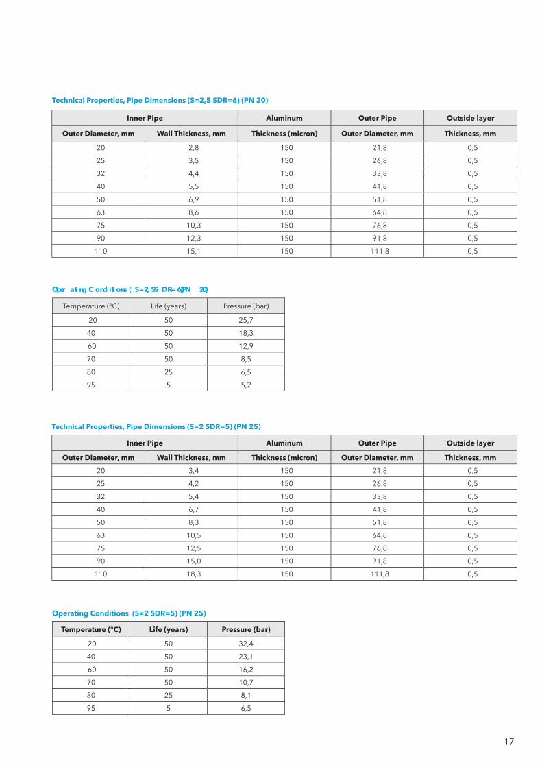
Technical Properties, Pipe Dimensions (S=2,5 SDR=6) (PN 20)
Technical Properties, Pipe Dimensions (S=2 SDR=5) (PN 25)
Inner Pipe Aluminum Outer Pipe Outside layer
Outer Diameter, mm Wall Thickness, mm Thickness (micron) Outer Diameter, mm Thickness, mm
20 3,4 150 21,8 0,5
25 4,2 150 26,8 0,5
32 5,4 150 33,8 0,5
40 6,7 150 41,8 0,5
50 8,3 150 51,8 0,5
63 10,5 150 64,8 0,5
75 12,5 150 76,8 0,5
90 15,0 150 91,8 0,5
110 18,3 150 111,8 0,5
Operating Conditions (S=2 SDR=5) (PN 25)
Temperature (°C ) Life (years) Pressure (bar)
20 50 32,4
40 50 23,1
60 50 16,2
70 50 10,7
80 25 8,1
95 5 6,5
Oper ati ng C ond iti ons ( S=2, 5 S DR= 6) (PN 20)
Temperature (°C ) Life (years) Pressure (bar)
20 50 25,7
40 50 18,3
60 50 12,9
70 50 8,5
80 25 6,5
95 5 5,2
18
Pipe length
(m)
Temperature variation ∆T in K
1 5 10 20 30 40 50 60 70 80
Linear expansion ∆L (mm)
1.0 0,03 0,15 0.30 0.60 0.90 1.20 1.50 1.80 2.10 2.40
2.0 0,06 0,30 0.60 1.20 1.80 2.40 3.00 3.60 4.20 4.80
3.0 0,09 0,45 0.90 1.80 2.70 3.60 4.50 5.40 6.30 7.20
4.0 0,12 0,60 1.20 2.40 3.60 4.80 6.00 7.20 8.40 9.60
5.0 0,15 0,75 1.50 3.00 4.50 6.00 7.50 9.00 10.50 12.00
6.0 0,18 0,90 1.80 3.60 5.40 7.20 9.00 10.80 12.80 14.40
7.0 0,21 1,05 2.10 4.20 6.43 8.40 10.50 12.60 14.70 16.80
8.0 0,24 1,20 2.40 4.80 7.20 9.60 12.00 14.40 16.80 19.20
9.0 0,27 1,35 2.70 5.40 8.10 10.80 13.50 16.20 18.90 21.60
10.0 0,30 1,50 3.00 6.00 9.00 12.00 15.00 18.00 21.00 24.00
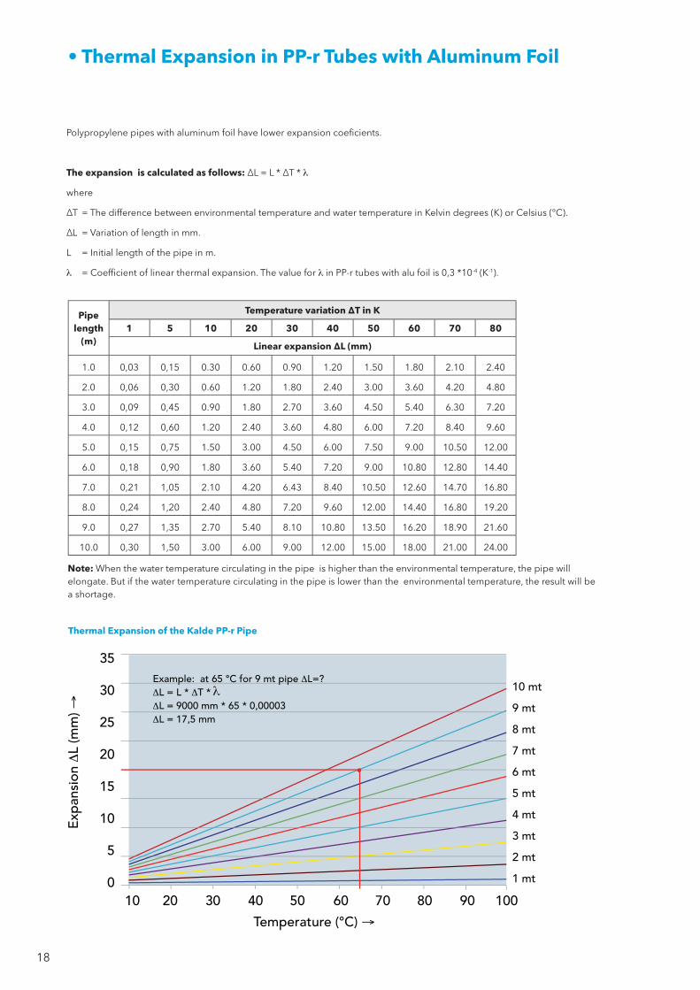
• Thermal Expansion in PP-r Tubes with Aluminum Foil
Note: When the water temperature circulating in the pipe is higher than the environmental temperature, the pipe will elongate. But if the water temperature circulating in the pipe is lower than the environmental temperature, the result will be a shortage.
Thermal Expansion of the Kalde PP-r Pipe
l
Polypropylene pipes with aluminum foil have lower expansion coeficients.
The expansion is calculated as follows: ∆L = L * ∆T * l
where
∆T = The difference between environmental temperature and water temperature in Kelvin degrees (K) or Celsius (°C).
∆L = Variation of length in mm.
L = Initial length of the pipe in m.
l = Coefficient of linear thermal expansion. The value for lin PP-r tubes with alu foil is 0,3 *10-4 (K-1).

19
• Polypropylene Pipes with Fiberglass
Expansion Comparison Between PP Pipes with Fiberglass and Standard Pipe
This pipe consists of three layers: the pipe and the coat are made of PP-r with a fiberglas-mixed PP-r inbetween.
Characteristics
- Hygenic.
- Resistance to chemicals.
- High resistance to pressure and heat.
- Low heat loss.
- Low pressure loss due to the smoothness.
- Low thermal expansion.
- Expansion: 0.035 mm/mK.
- Lighter than standard PP-r pipes.
- The heat conductivity is less than alu-foiled PP-r pipes and same as PP-r standard pipes.
- Higher discharge related to the bigger inner diameter.
Advantages
- %75 less expansion than standard PP-r pipes.
- No need to shave the pipe for welding.
- Lower costs, you use less brackets due to less expansion.
- More resistance despite smaller wall thickness.
- %20 more flow than standard pipes.
- Same or lower heat conductivity in comparison to standard PP-r and aluminum foiled pipes.
- Easy welding and mounting.
20
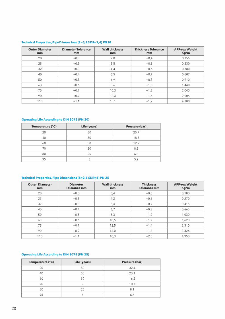
Technical Properties, Pipe Dimensions (S=2,5 SDR=6) PN 25
Outer Diameter mm
DiameterTolerance mm
Wall thickness mm
ThicknessTolerance mm
APP-rox WeightKg/m
20 +0,3 3,4 +0,5 0,180
25 +0,3 4,2 +0,6 0.270
32 +0,3 5,4 +0,7 0.415
40 +0,4 6,7 +0,8 0,665
50 +0,5 8,3 +1,0 1,030
63 +0,6 10,5 +1,2 1,620
75 +0,7 12,5 +1,4 2,310
90 +0,9 15,0 +1,6 3,326
110 +1,1 18,3 +2,0 4,950
Operating Life According to DIN 8078 (PN 25)
Temperature (°C) Life (years) Pressure (bar)
20 50 32,4
40 50 23,1
60 50 16,2
70 50 10,7
80 25 8,1
95 5 6,5
Outer Diameter mm
Diameter Tolerance mm
Wall thickness mm
Thickness Tolerancemm
APP-rox WeightKg/m
20 +0,3 2,8 +0,4 0,155
25 +0,3 3,5 +0,5 0,230
32 +0,3 4,4 +0,6 0,380
40 +0,4 5.5 +0,7 0,607
50 +0,5 6.9 +0,8 0,910
63 +0,6 8.6 +1,0 1,440
75 +0,7 10.3 +1,2 2,040
90 +0,9 12.3 +1,4 2,905
110 +1,1 15.1 +1,7 4,380
Technical Proper ties, Pipe D imens ions (S =3,2 S DR=7,4) PN 20
Operating Life According to DIN 8078 (PN 20)
Temperature (°C ) Life (years) Pressure (bar)
20 50 25,7
40 50 18,3
60 50 12,9
70 50 8,5
80 25 6,5
95 5 5,2
21
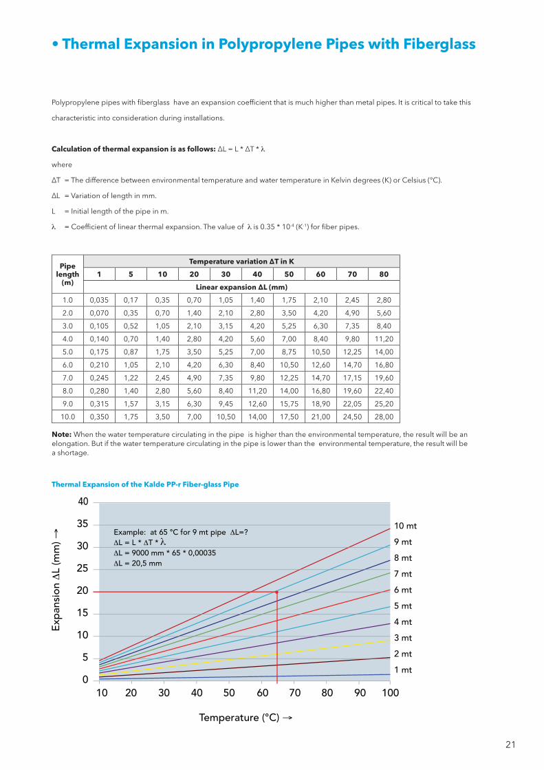
• Thermal Expansion in Polypropylene Pipes with Fiberglass
Pipe length
(m)
Temperature variation ∆T in K
1 5 10 20 30 40 50 60 70 80
Linear expansion ∆L (mm)
1.0 0,035 0,17 0,35 0,70 1,05 1,40 1,75 2,10 2,45 2,80
2.0 0,070 0,35 0,70 1,40 2,10 2,80 3,50 4,20 4,90 5,60
3.0 0,105 0,52 1,05 2,10 3,15 4,20 5,25 6,30 7,35 8,40
4.0 0,140 0,70 1,40 2,80 4,20 5,60 7,00 8,40 9,80 11,20
5.0 0,175 0,87 1,75 3,50 5,25 7,00 8,75 10,50 12,25 14,00
6.0 0,210 1,05 2,10 4,20 6,30 8,40 10,50 12,60 14,70 16,80
7.0 0,245 1,22 2,45 4,90 7,35 9,80 12,25 14,70 17,15 19,60
8.0 0,280 1,40 2,80 5,60 8,40 11,20 14,00 16,80 19,60 22,40
9.0 0,315 1,57 3,15 6,30 9,45 12,60 15,75 18,90 22,05 25,20
10.0 0,350 1,75 3,50 7,00 10,50 14,00 17,50 21,00 24,50 28,00
Note: When the water temperature circulating in the pipe is higher than the environmental temperature, the result will be an elongation. But if the water temperature circulating in the pipe is lower than the environmental temperature, the result will be a shortage.
Thermal Expansion of the Kalde PP-r Fiber-glass Pipe
l
Polypropylene pipes with fiberglass have an expansion coefficient that is much higher than metal pipes. It is critical to take this
characteristic into consideration during installations.
Calculation of thermal expansion is as follows: ∆L = L * ∆T *l
where
∆T = The difference between environmental temperature and water temperature in Kelvin degrees (K) or Celsius (°C).
∆L = Variation of length in mm.
L = Initial length of the pipe in m.
l = Coefficient of linear thermal expansion. The value of l is 0.35 * 10-4 (K-1) for fiber pipes.

22
• Mounting and Installation
Linear Expansion DL (mm)
Leng
th o
f the
ben
din
g p
art (
mt)
Thermal Tensions
Piping systems are used to convey gas and fluids in a broad area with various pressure and temperatures. Piping materials go
through size changes due to changes in temperature, external forces, time-dependent effects (fatigue and relaxation), changes
in internal structure, humidity value and some other reasons. When considering pipe systems, the most important elements
that require taking measures are temperature and external forces as well as the weight of pipe itself, weight of fluid being
conveyed, operating temperature, and internal and external pressure.
Thermal tensions result from static points blocking the pipe motion in all directions and preventing pipe’s
angular movement, and the sliding support that hinders the same in two directions.
A piping system should be designed so as to have the longest service life against its intended use, the lowest business and
investment cost, and to work in the safest way. This can be ensured by making a thermal tension analysis of the installation.
Therefore, thermal tensions must be taken into the same consideration from the basic household installation to those with the
highest pressure and temperature values.
Amount of thermal tension in piping is determined upon temperature difference in the pipeline, pipe length and material
characteristics. Amount of thermal tension of PP-r pipe can be determined using the thermal expansion diagram below.

23
Figure - 4 Calculation Distance of Bending Part
Fixed Point
Sliding Point
Omega Fixed Point U Bend Compensator
L L L L
Fixed Point Fixed PointSliding Point Belows MetalCompensator
L L
FP = Fixed PointSP = Slinding Point
∆LFP FP
FP
SP
X min
SP∆L ∆L ∆L
Ls
L
∆L
FP
FP
SP Ls
∆L
FP = Fixed PointSP = Slinding Point
Figure - 2 Metal compansator
Figure - 3 U Part (Calculation Distance of Bending Part )
Figure - 1 Omega and U part
• Removing Expansions from Installation
Omega and (U) Elements
Omega and U parts designed for use in hot pipes. As an alternative, metal (belows) compansation also can used instead of
the omega and U parts.. these parts, are used to get extensions in straight pipelines. these components, application forms
and calculations of the system are given below.
Use some shape:

24
2. The calculation of the bending length
d = 63 mm
∆L = 72 mm
C = 15
Ls = c x d x ∆L
Ls = 15 x 63 x 72 = 1010 mm
• Calculation of Elongation
Pipe out diamter,
mm
Linear Expansion ∆L (mm)
20 30 40 50 60 70 80
Length of the bending part in (m)
Ø20 0.30 0.36 0.42 0.47 0.51 0.56 0.60
Ø25 0.33 0.41 0.47 0.53 0.58 0.62 0.67
Ø32 0.37 0.46 0.53 0.60 0.65 0.70 0.75
Ø40 0.42 0.52 0.60 0.67 0.73 0.79 0.84
Ø50 0.47 0.58 0.67 0.75 0.82 0.88 0.94
Ø63 0.53 0.65 0.75 0.84 0.90 0.99 1.06
Ø75 0.58 0.71 0.82 0.91 1.00 1.08 1.16
Ø90 0.63 0.78 0.90 1.00 1.10 1.19 1.27
Ø110 0.70 0.86 0.99 1.11 1.21 1.31 1.40
Kalde Length of the Bending Part
Example
1.Calculation of elongation
Temperature difference between cold water and environment
Input
l = 0.15 mm/m-K
L = 12 meter
∆T = 40 ºC
Required
∆L = l x ∆T x L
∆L = 0.15 x 40 x 12 = 72 mm
Length of the bending part is calculated with the following formula.
Ls = c x d x ∆L.
Ls = Lenght of the bending part mm.
d = Outer dimater of the Kalde pipe mm.
∆L = Variation of length mm.
C = 15 (material based constant of Kalde pipe).
FP = Fixed Point.
MP = Moving Point.

25
• Support Intervals
Kalde PP-r Pipe SDR:6 – SDR:7.4 (PN20 – PN16)
Temperature
∆T (K)
Pipe diameter d (mm)
20 25 32 40 50 63 75 90 110
Support intervals in cm
20 60 70 90 100 120 140 150 160 180
30 60 70 90 100 120 140 150 160 180
40 60 70 80 90 110 130 140 150 170
50 60 70 80 90 110 130 140 150 170
60 50 60 70 80 100 110 120 140 160
70 50 60 70 80 90 100 110 120 140
Kalde Foil Pipe SDR:6 – SDR:7.4 (PN25 – PN20)
Temperature
∆T (K)
Pipe diameter d (mm)
20 25 32 40 50 63 75 90 110
Support intervals in cm
20 110 120 140 160 180 200 210 220 240
30 110 120 140 160 180 200 210 220 230
40 110 120 130 150 170 190 200 210 220
50 110 120 130 150 170 190 200 210 210
60 100 110 120 140 160 180 190 200 200
70 90 100 110 130 150 170 180 190 200
Kalde PP-r Pipe SDR:11 (PN10) (Temperature of Medium:20°C)
Temperature
∆T (K)
Pipe diameter d (mm)
20 25 32 40 50 63 75 90 110
Support intervals in cm
20 60 70 90 100 120 140 150 160 180
Kalde Fiberglas Pipe SDR:6 – SDR:7.4 (PN25 – PN20)
Temperature ∆T
Pipe diameter d (mm)
20 25 32 40 50 63 75 90 110
Support intervals in cm
20 90 100 110 120 140 160 170 180 200
30 90 100 110 120 140 160 170 180 200
40 80 90 100 110 130 150 160 170 180
50 80 90 100 110 130 150 160 170 180
60 70 80 90 100 120 140 150 160 170
70 70 80 90 100 120 120 140 150 160

26
Outer Diameter (mm) HeatingSecs
JoiningSecs Cooling Time (minutes) Welding length
mm
20 7 4 2 16
25 7 4 3 18
32 8 6 4 20
40 12 6 4 22
50 18 6 5 26
63 24 8 6 29
75 30 10 8 32
90 40 11 8 38
110 50 12 8 42
Diameter (Ø), mm E, mm
20 15
25 17
32 19
40 22
50 24
63 28
75 32
90 38
110 42
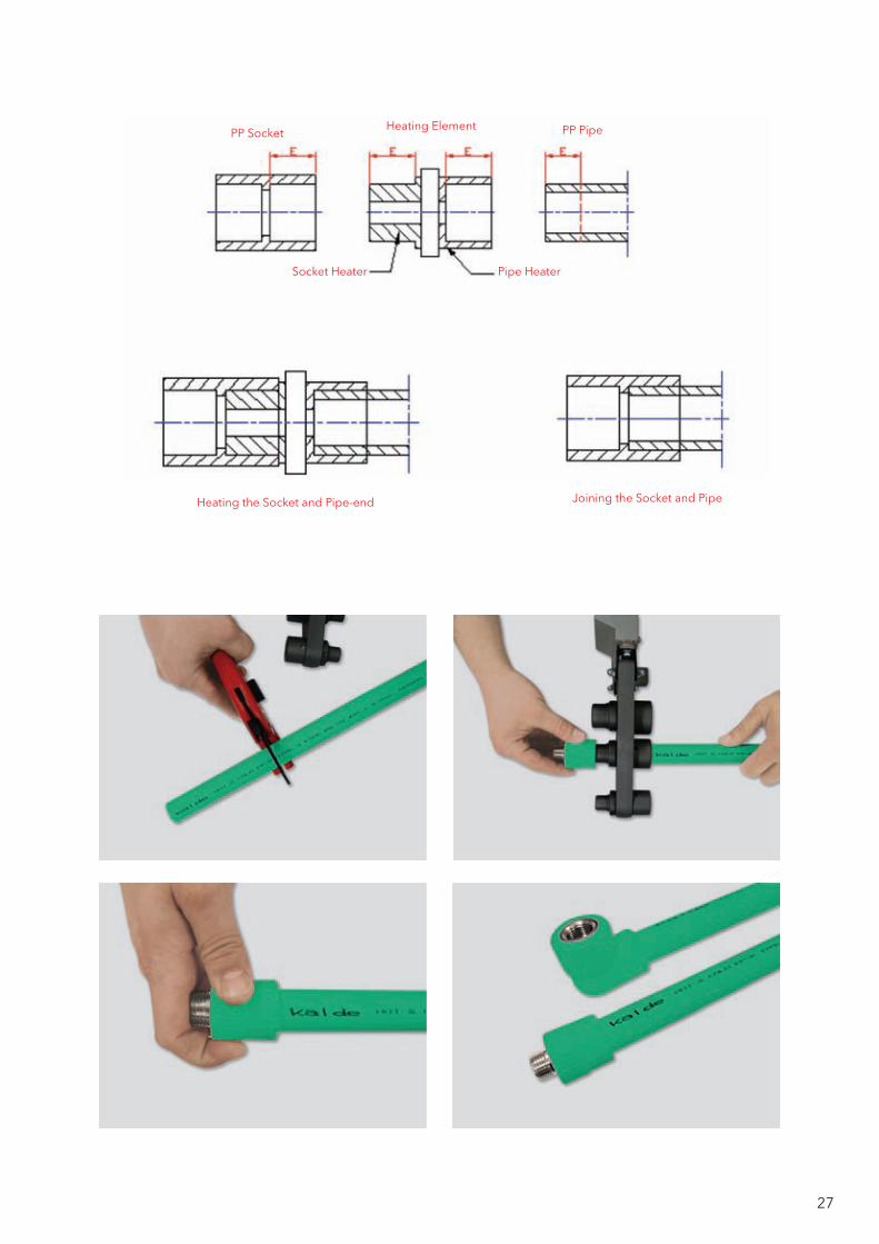
• Welding Technique (DVS 2208)
Welding takes only a few seconds. The quality of an installation depends on the tightness, stability and lifetime of its connections.
When the welded joint cools down, it can be fully loaded. PPR pipes and fittings, combined with socket welding. This operation
is done with welding machines. Surfaces to be welded must be clean.
Welding sequence:
• According to the size of pipes and fittings welding part (Teflon coated) mounted welding machine, welding parts is
heated until it reaches the temperature (260 ° C ± 10).
• To be welded pipe, pipe cutting scissors cut perpendicular to the axis of the pipe, (outer foil pipes, after cutting proses
the on surface of the pipe aluminum foil must shaved with shave aparatus.)
• Pipe welding distance is marked. (see Chart of welding)
• Pipes and fittings, gently inserted into welding parts.
• A certain period of the welding machine the heated pipe and fitting, getting out from welding parts, and are combined
with each other. (see Chart of welding)
27
Heating the Socket and Pipe-end
Socket Heater
PP Socket PP PipeHeating Element
Pipe Heater
Joining the Socket and Pipe
28
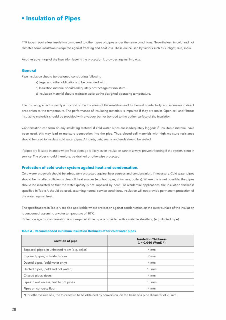
• Insulation of Pipes
Location of pipe Insulation Thicknessl= 0,040 W/mK *)
Exposed pipes, in unheated room (e.g. cellar) 4 mm
Exposed pipes, in heated room 9 mm
Ducted pipes, (cold water only) 4 mm
Ducted pipes, (cold and hot water ) 13 mm
Chased pipes, risers 4 mm
Pipes in wall recess, next to hot pipes 13 mm
Pipes on concrete floor 4 mm
*) for other values of l, the thickness is to be obtained by conversion, on the basis of a pipe diameter of 20 mm.
Table A - Recommended minimum insulation thickness of for cold water pipes
PPR tubes require less insulation compared to other types of pipes under the same conditions. Nevertheless, in cold and hot
climates some insulation is required against freezing and heat loss. These are caused by factors such as sunlight, rain, snow.
Another advantage of the insulation layer is the protection it provides against impacts.
GeneralPipe insulation should be designed considering following:
a) Legal and other obligations to be complied with.
b) Insulation material should adequately protect against moisture.
c) Insulation material should maintain water at the designed operating temperature.
The insulating effect is mainly a function of the thickness of the insulation and its thermal conductivity, and increases in direct
proportion to the temperature. The performance of insulating materials is impaired if they are moist. Open-cell and fibrous
insulating materials should be provided with a vapour barrier bonded to the outher surface of the insulation.
Condensation can form on any insulating material if cold water pipes are inadequately lagged; if unsuitable material have
been used, this may lead to moisture penetration into the pipe. Thus, closed-cell materials with high moisture resistance
should be used to insulate cold water pipes. All joints, cuts, seams and ends should be sealed.
İf pipes are located in areas where frost damage is likely, even insulation cannot always prevent freezing if the system is not in
service. The pipes should therefore, be drained or otherwise protected.
Protection of cold water system against heat and condensation.Cold water pipework should be adequately protected against heat sources and condensation, if necessary. Cold water pipes
should be installed sufficiently clear off heat sources (e.g. hot pipes, chimneys, boilers). Where this is not possible, the pipes
should be insulated so that the water quality is not impaired by heat. For residential applications, the insulation thickness
specified in Table A should be used, assuming normal service conditions. Insulation will not provide permanent protection of
the water against heat.
The specifications in Table A are also applicable where protection against condensation on the outer surface of the insulation
is concerned, assuming a water temperature of 10°C.
Protection against condensation is not required if the pipe is provided with a suitable sheathing (e.g. ducted pipe).

29
• Protection of Hot Water Pipes Against Heat Loss
• Thermal Insulation of Warm Water Pipes
The decree for energy saving thermal protection and energy saving technique for buildings shall be considered. Decree for
energy saving (EnEV-in Germany) regulates the thermal insulation of pipes and fittings.
Line Type of Pipe / Fitting Minimum Thickness of insulation refered to thermal conductivity of l=0.035 W/mK
1 Inner diameter up to 22 mm 20 mm
2 Inner diameter more than 22 mm up to 35 mm 30 mm
3 Inner diameter more than 35 mm up to 100 mm Same as inner diameter
4 Inner diameter more than 100 mm 100 mm
Table B - Minimum Thickness of Insulation Warm Water Pipes
Insulation Thickness
Pipe O uter Diameter
Available Thickness Acc.to 2 HAVOl = 0.035 W/mK
Insulation Thickness in Kalde Pipesl = 0.035 W/mK
20x3,4 mm 20 mm 20 mm
25x4,2 mm 20 mm 20 mm
32x5,4 mm 20 mm 20 mm
40x6,7 mm 30 mm 30 mm
50x8,3 mm 30 mm 30 mm
63x10,5 mm 42 mm 42 mm
75x12,5 mm 50 mm 50 mm
90x15,0mm 60 mm 60 mm
110x18,3mm 73,4 mm 73,4 mm
The minimum requirements specified in the Heizungsanlagen-Verordnung (heating system regulation) shall be complied with
for restricting the heat loss of hot pipes, including circulation pipes.

30
• Calculation Of Economic Pipe Insulation Material Thickness
Economic Insulation Thickness Chart
Iso
latio
n Th
ickn
ess,
mm
Pip
e D
iam
eter
, mm
110 mm
75 mm
63 mm
40 mm
20 mm
260
200
160
120
100
80
60
50
40
30
25
0,5 1,0 2 3 5 10 20 50 100 150
Factor F = P * (Ti - Td) * n * l·10-5
Optimum values of the thickness of the pipe insulation material is shown in chart of economic insulation thickness.
Such F factor
P = Heat energy costs (€ / kWh) in Euro, n = Annual operating time (hours / year) l = Thermal conductivity coefficient of insulation material (W / mk) Ti = Fluid temperature, ° C Td = The ambient temperature, ° C
F = P * (Ti - Td) * n * l·10-5
F = 30 x (80-20) x 8000 x 0.035 x 10-5
F = 5.04Looking at the economic insulation
thickness chart (below), only the insulation thickness of 50 mm.
Example
Pipe diameter: 75mm The temperature of water in the pipe: 80 ° C, Ambient temperature: 20 ° C Heat energy cost: 30 € / kWh,Line, annual working hours: 8000hInsulation material, thermal conductivity coefficient: 0.035 w / mk In this case, what is the economic pipe insulation thickness?
• Several Thermal Insulation Materials and Their Properties
Materials User’s Location Temperature Range Coefficient of Thermal Conductivity
Glass woolHeating systems, pipes are used to provide heat and sound insulation.
(-20°C) – (+250°C) 20°C de 0,039w/mk
Polyethylene foam Central heating, cooling, air-conditioning systems (-80°C) – (+95°C) 10°C de 0,033w/mk 40°C de 0,040w/mk
Elostrometrik polyolefin
Central heating, cooling, ventilation, heat pump systems
(-80°C) – (+95°C) 10°C de 0,033w/mk 40°C de 0,038w/mk
Polyurethane foam Cooling tanks (-100°C) – (+90°C) 20°C de 0,022w/mk
31
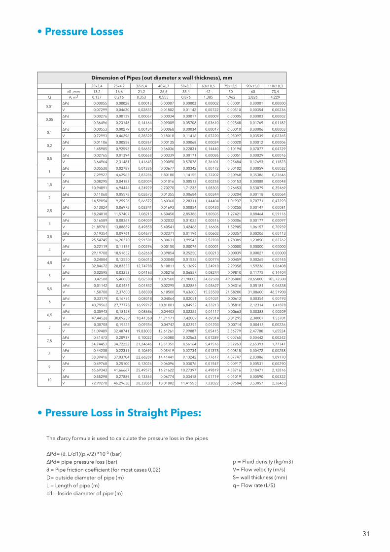
• Pressure Losses
• Pressure Loss in Straight Pipes:
The d’arcy formula is used to calculate the pressure loss in the pipes
ΔPd= (∂. L/d1)(p.v/2) *10-5 (bar)
ΔPd= pipe pressure loss (bar)
∂ = Pipe friction coefficient (for most cases 0,02)
D= outside diameter of pipe (m)
L = Length of pipe (m)
d1= Inside diameter of pipe (m)
p = Fluid density (kg/m3)
V= Flow velocity (m/s)
S= wall thickness (mm)
q= Flow rate (L/S)
Dimension of Pipes (out diameter x wall thickness), mm20x3,4 25x4,2 32x5,4 40x6,7 50x8,3 63x10,5 75x12,5 90x15,0 110x18,3
d1, mm 13,2 16,6 21,2 26,6 33,4 42 50 60 73,4
Q A, m2 0,137 0,216 0,353 0,555 0,876 1,385 1,962 2,826 4,229
0,01 ∆Pd 0,00055 0,00028 0,00013 0,00007 0,00003 0,00002 0,00001 0,00001 0,00000
V 0,07299 0,04630 0,02833 0,01802 0,01142 0,00722 0,00510 0,00354 0,00236
0,05 ∆Pd 0,00276 0,00139 0,00067 0,00034 0,00017 0,00009 0,00005 0,00003 0,00002
V 0,36496 0,23148 0,14164 0,09009 0,05708 0,03610 0,02548 0,01769 0,01182
0,1 ∆Pd 0,00553 0,00279 0,00134 0,00068 0,00034 0,00017 0,00010 0,00006 0,00003
V 0,72993 0,46296 0,28329 0,18018 0,11416 0,07220 0,05097 0,03539 0,02365
0,2 ∆Pd 0,01106 0,00558 0,00267 0,00135 0,00068 0,00034 0,00020 0,00012 0,00006
V 1,45985 0,92593 0,56657 0,36036 0,22831 0,14440 0,10194 0,07077 0,04729
0,5 ∆Pd 0,02765 0,01394 0,00668 0,00339 0,00171 0,00086 0,00051 0,00029 0,00016
V 3,64964 2,31481 1,41643 0,90090 0,57078 0,36101 0,25484 0,17693 0,11823
1∆Pd 0,05530 0,02789 0,01336 0,00677 0,00342 0,00172 0,00102 0,00059 0,00032
V 7,29927 4,62963 2,83286 1,80180 1,14155 0,72202 0,50968 0,35386 0,23646
1,5 ∆Pd 0,08295 0,04183 0,02004 0,01016 0,00513 0,00258 0,00153 0,00088 0,00048
V 10,94891 6,94444 4,24929 2,70270 1,71233 1,08303 0,76453 0,53079 0,35469
2∆Pd 0,11060 0,05578 0,02673 0,01355 0,00684 0,00344 0,00204 0,00118 0,00064
V 14,59854 9,25926 5,66572 3,60360 2,28311 1,44404 1,01937 0,70771 0,47293
2,5 ∆Pd 0,13824 0,06972 0,03341 0,01693 0,00854 0,00430 0,00255 0,00147 0,00081
V 18,24818 11,57407 7,08215 4,50450 2,85388 1,80505 1,27421 0,88464 0,59116
3∆Pd 0,16589 0,08367 0,04009 0,02032 0,01025 0,00516 0,00306 0,00177 0,00097
V 21,89781 13,88889 8,49858 5,40541 3,42466 2,16606 1,52905 1,06157 0,70939
3,5 ∆Pd 0,19354 0,09761 0,04677 0,02371 0,01196 0,00602 0,00357 0,00206 0,00113
V 25,54745 16,20370 9,91501 6,30631 3,99543 2,52708 1,78389 1,23850 0,82762
4∆Pd 0,22119 0,11156 0,00296 0,00150 0,00076 0,00001 0,00000 0,00000 0,00000
V 29,19708 18,51852 0,62660 0,39854 0,25250 0,00213 0,00039 0,00027 0,00000
4,5 ∆Pd 0,24884 0,12550 0,06013 0,03048 0,01538 0,00774 0,00459 0,00265 0,00145
V 32,84672 20,83333 12,74788 8,10811 5,13699 3,24910 2,29358 1,59236 1,06408
5∆Pd 0,02595 0,03253 0,04163 0,05216 0,06557 0,08244 0,09810 0,11775 0,14404
V 3,42500 5,40000 8,82500 13,87500 21,90000 34,62500 49,05000 70,65000 105,72500
5,5 ∆Pd 0,01142 0,01431 0,01832 0,02295 0,02885 0,03627 0,04316 0,05181 0,06338
V 1,50700 2,37600 3,88300 6,10500 9,63600 15,23500 21,58200 31,08600 46,51900
6∆Pd 0,33179 0,16734 0,08018 0,04064 0,02051 0,01031 0,00612 0,00354 0,00193
V 43,79562 27,77778 16,99717 10,81081 6,84932 4,33213 3,05810 2,12314 1,41878
6,5 ∆Pd 0,35943 0,18128 0,08686 0,04403 0,02222 0,01117 0,00663 0,00383 0,00209
V 47,44526 30,09259 18,41360 11,71171 7,42009 4,69314 3,31295 2,30007 1,53701
7∆Pd 0,38708 0,19523 0,09354 0,04742 0,02392 0,01203 0,00714 0,00413 0,00226
V 51,09489 32,40741 19,83003 12,61261 7,99087 5,05415 3,56779 2,47700 1,65524
7,5 ∆Pd 0,41473 0,20917 0,10022 0,05080 0,02563 0,01289 0,00765 0,00442 0,00242
V 54,74453 34,72222 21,24646 13,51351 8,56164 5,41516 3,82263 2,65393 1,77347
8∆Pd 0,44238 0,22311 0,10690 0,05419 0,02734 0,01375 0,00815 0,00472 0,00258
V 58,39416 37,03704 22,66289 14,41441 9,13242 5,77617 4,07747 2,83086 1,89170
9∆Pd 0,49768 0,25100 0,12026 0,06096 0,03076 0,01547 0,00917 0,00531 0,00290
V 65,69343 41,66667 25,49575 16,21622 10,27397 6,49819 4,58716 3,18471 2,12816
10∆Pd 0,55298 0,27889 0,13363 0,06774 0,03418 0,01719 0,01019 0,00590 0,00322
V 72,99270 46,29630 28,32861 18,01802 11,41553 7,22022 5,09684 3,53857 2,36463

32
• Pipe Laying
Pipes in the ground should be isolated against thermal insulation and corrosion.
Penetration of moisture and water through the pipes underground and insulation material should be avoided.
Water in buried service pipes may be polluted by waste water. Thus, where the distance between drinking and waste water
pipes does not exceed 1 m, the former shall not be laid deeper than the latter. The minimum clear distance between drinking
water pipes and other pipes shall be 0.2 m. Where this distance cannot be maintained, protective measures (e.g. enclosing
pipe in a duct) shall be taken.
Pipes embedded in a building element (e.g. wall or floor) shall be suitably wrapped or coated so as to ensure that the pipe and
building element are not in direct contact.
• Test Procedure (DIN 1988-2)
The finished installation shall be filtered and vacuumed in order to be filled with water to start testing.
Pressure testing shall be carried out in two stages, the first stage being sufficient for smaller sections of the system (e.g. for
testing supply and branch pipes in wet rooms).
a) For the first stage, a test pressure equal to the permissible working pressure plus 5 bar shall be produced twice
within 30 minutes at 10-minute intervals. Than it shall be checked whether, over a further period of 30 minutes,
the pressure has dropped by more than 0,6 bar (with a rate of 0.1 bar per minute) and leakage has occurred.
b) The second stage shall follow the first stage without interval and shall last two hours. Then, it shall be checked
whether the pressure has dropped by more than 0.2 bar and the pipework shows any signs of leakage.
• Points to Pay Attention to When Installing Polypropylene Pipes and Fittings
• Do not expose the pipes and fittings to the sun. Protect the pipes against hard and sharp objects. Do not use defective
pipes for installation.
• Bend the pipes with hot air. Never use fire when heating the pipes.
• The pipes and the fittings to be installed should be clean.
• Cut the pipes, perpendicular to the axis of pipe with a proper scissor, do not use other sharp objects that can cause im-
purity in the pipes.
• Mark the welding length on the pipe before welding.
• information about the welding process (heating time, standby time, cooling time, etc.) take the manufacturer’s catalog.
• Protect polypropylene pipe and fittings where water may freze. expansion due to freezing water inside the pipe may
damage it.
• After shaving the aluminum layer make sure that there is no aluminum parts on the welding surface, otherwise it will cause
leakage.
• Cold weather weakens the resistance of polypropylene against hit and it becomes fragile. Protect the pipes against hit
when there is a risk of freezing.
• To prevent leaks in your installation use teflon tapes with the threaded fittings.
• All PP fittings and pipes are available in white/grey/green.
• Nominal pressure: PN25 for fittings.
• Packaging quantities are subject to change without notice.

PP-r Products

34
Polypropylene Tubes
PN-10 Polypropylene Tube
Code D (mm) m/bundle
3201-tbe-200010 20 100
3201-tbe-250010 25 80
3201-tbe-320010 32 40
3201-tbe-400010 40 32
3201-tbe-500010 50 20
3201-tbe-630010 63 16
3201-tbe-750010 75 12
3201-tbe-900010 90 8
3201-tbe-110010 110 4
3201-tbe-125010 125
PN-16 Polypropylene Tube
Code D (mm) m/bundle
3201-tbe-200016 20 100
3201-tbe-250016 25 80
3201-tbe-320016 32 40
3201-tbe-400016 40 32
3201-tbe-500016 50 20
3201-tbe-630016 63 16
3201-tbe-750016 75 12
3201-tbe-900016 90 8
3201-tbe-110016 110 4
3201-tbe-125016 125
PN-20 Polypropylene Tube
Code D (mm) m/bundle
3201-tbe-200000 20 100
3201-tbe-250000 25 80
3201-tbe-320000 32 40
3201-tbe-400000 40 32
3201-tbe-500000 50 20
3201-tbe-630000 63 16
3201-tbe-750000 75 12
3201-tbe-900000 90 8
3201-tbe-110000 110 4
3201-tbe-125000 125
*Our several pipes could be produced on demand also with ultraviolet resistance black layer.

35
Polypropylene Tubes
PN-16 Polypropylene Tube with Fiberglass - Orangepipe
Code D (mm) m/bundle
3201-tfr-200016 20 100
3201-tfr-250016 25 80
3201-tfr-320016 32 40
3201-tfr-400016 40 32
3201-tfr-500016 50 20
3201-tfr-630016 63 16
3201-tfr-750016 75 12
3201-tfr-900016 90 8
3201-tfr-110016 110 4
3201-tfr-125016 125 4
PN-20 Polypropylene Tube with Fiberglass - Orangepipe
Code D (mm) m/bundle
3201-tfr-200020 20 100
3201-tfr-250020 25 80
3201-tfr-320020 32 40
3201-tfr-400020 40 32
3201-tfr-500020 50 20
3201-tfr-630020 63 16
3201-tfr-750020 75 12
3201-tfr-900020 90 8
3201-tfr-110020 110 4
3201-tfr-125020 125 4
PN-25 Polypropylene Tube with Fiberglass - Orangepipe
Code D (mm) m/bundle
3201-tfr-200000 20 100
3201-tfr-250000 25 80
3201-tfr-320000 32 40
3201-tfr-400000 40 32
3201-tfr-500000 50 20
3201-tfr-630000 63 16
3201-tfr-750000 75 12
3201-tfr-900000 90 8
3201-tfr-110000 110 4
3201-tfr-125000 125 4
*Our several pipes could be produced on demand also with ultraviolet resistance black layer.

36
PN-25 Polypropylene Tube - Supperpipe
Code D (mm) m/bundle
3201-tmf-200000 20 100
3201-tmf-250000 25 80
3201-tmf-320000 32 40
3201-tmf-400000 40 32
3201-tmf-500000 50 20
3201-tmf-630000 63 16
PN-25 Polypropylene Tube with Alu Oxi - SupperOXI
Code D (mm) m/bundle
3201-tox-200000 20 100
3201-tox-250000 25 80
3201-tox-320000 32 40
3201-tox-400000 40 32
3201-tox-500000 50 20
3201-tox-630000 63 16
PP Bridge
Code D (mm) Pcs/Box
3201-twc-200000 20 125
3201-twc-250000 25 75
3201-twc-320000 32 30
3201-twc-400002 40 25
PP C - Bridge
Code D (mm) Pcs/Box
3201-twc-200001 20 250
3201-twc-250001 25 125
3201-twc-320001 32 60
Polypropylene Tubes
*Our several pipes could be produced on demand also with ultraviolet resistance black layer.

37
Polypropylene Fittings
Elbow 45°
Code Size Pcs/Box
3211-elb-200045 20 500
3211-elb-250045 25 300
3211-elb-320045 32 175
3211-elb-400045 40 90
3211-elb-500045 50 50
3211-elb-630045 63 25
3211-elb-750045 75 12
3211-elb-900045 90 12
3211-elb-110045 110 6
Elbow 90°
Code Size Pcs/Box
3211-elb-200000 20 500
3211-elb-250000 25 300
3211-elb-320000 32 140
3211-elb-400000 40 70
3211-elb-500000 50 36
3211-elb-630000 63 20
3211-elb-750000 75 16
3211-elb-900000 90 6
3211-elb-110000 110 4
Tail Elbow 45°
Code Size Pcs/Box
3211-elt-200045 20 400
3211-elt-250045 25 250
Tail Elbow 90°
Code Size Pcs/Box
3211-elt-200000 20 400
3211-elt-250000 25 250

38
Polypropylene Fittings
Inegal Tee
Code Size Pcs/Box
3211-tio-202520 20 x 25 x 20 200
3211-tio-252020 25 x 20 x 20 200
3211-tio-252025 25 x 20 x 25 240
3211-tio-252520 25 x 25 x 20 200
3211-tio-253225 25 x 32 x 25 110
3211-tio-322020 32 x 20 x 20 130
3211-tio-322025 32 x 20 x 25 125
3211-tio-322032 32 x 20 x 32 115
3211-tio-322520 32 x 25 x 20 125
3211-tio-322525 32 x 25 x 25 120
3211-tio-322532 32 x 25 x 32 115
3211-tio-323225 32 x 32 x 25 100
3211-tio-402040 40 x 20 x 40 75
3211-tio-402540 40 x 25 x 40 75
3211-tio-403240 40 x 32 x 40 60
3211-tio-502050 50 x 20 x 50 40
3211-tio-502550 50 x 25 x 50 40
3211-tio-503250 50 x 32 x 50 30
3211-tio-504050 50 x 40 x 50 30
3211-tio-632063 63 x 20 x 63 24
3211-tio-632563 63 x 25 x 63 24
3211-tio-633263 63 x 32 x 63 24
3211-tio-634063 63 x 40 x 63 20
3211-tio-635063 63 x 50 x 63 20
3211-tio-752075 75 x 20 x 75 12
3211-tio-752575 75 x 25 x 75 12
3211-tio-753275 75 x 32 x 75 12
3211-tio-754075 75 x 40 x 75 12
3211-tio-755075 75 x 50 x 75 12
3211-tio-756375 75 x 63 x 75 12
3211-tio-906390 90 x 63 x 90 6
3211-tio-115011 110 x 50 x 110 3
3211-tio-116311 110 x 63 x 110 3

39
Polypropylene Fittings
Tee
Code Size Pcs/Box
3211-teo-200000 20 300
3211-teo-250000 25 200
3211-teo-320000 32 100
3211-teo-400000 40 50
3211-teo-500000 50 30
3211-teo-630000 63 16
3211-teo-750000 75 12
3211-teo-900000 90 4
3211-teo-110000 110 2
Coupling
Code Size Pcs/Box
3211-muf-200000 20 600
3211-muf-250000 25 400
3211-muf-320000 32 200
3211-muf-400000 40 130
3211-muf-500000 50 75
3211-muf-630000 63 45
3211-muf-750000 75 28
3211-muf-900000 90 20
3211-muf-110000 110 10
Reducing Female Coupling
Code Size Pcs/Box
3211-rdf-252000 25 x 20 400
3211-rdf-322000 32 x 20 250
3211-rdf-322500 32 x 25 250
3211-rdf-402000 40 x 20 150
3211-rdf-402500 40 x 25 150

40
Polypropylene Fittings
Reducing Coupling
Code Size Pcs/Box
3211-rdc-252000 25 x 20 700
3211-rdc-322000 32 x 20 500
3211-rdc-322500 32 x 25 400
3211-rdc-402000 40 x 20 300
3211-rdc-402500 40 x 25 300
3211-rdc-403200 40 x 32 200
3211-rdc-502000 50 x 20 175
3211-rdc-502500 50 x 25 175
3211-rdc-503200 50 x 32 125
3211-rdc-504000 50 x 40 100
3211-rdc-632000 63 x 20 90
3211-rdc-632500 63 x 25 90
3211-rdc-633200 63 x 32 80
3211-rdc-634000 63 x 40 70
3211-rdc-635000 63 x 50 56
3211-rdc-752000 75 x 20 60
3211-rdc-752500 75 x 25 60
3211-rdc-753200 75 x 32 55
3211-rdc-754000 75 x 40 55
3211-rdc-755000 75 x 50 50
3211-rdc-756300 75 x 63 36
3211-rdc-905000 90 x 50 36
3211-rdc-906300 90 x 63 36
3211-rdc-907500 90 x 75 24
3211-rdc-110630 110 x 63 16
3211-rdc-110750 110 x 75 16
3211-rdc-110900 110 x 90 16
41
Polypropylene Fittings
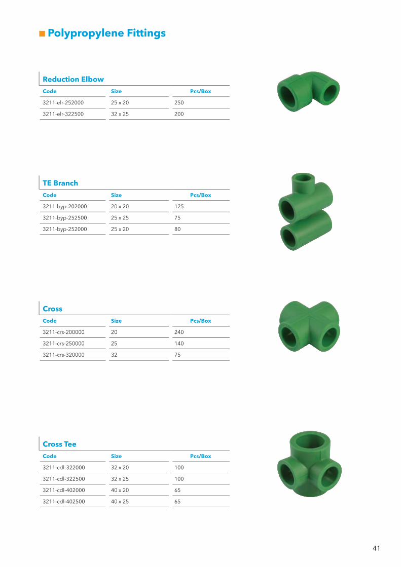
Reduction Elbow
Code Size Pcs/Box
3211-elr-252000 25 x 20 250
3211-elr-322500 32 x 25 200
TE Branch
Code Size Pcs/Box
3211-byp-202000 20 x 20 125
3211-byp-252500 25 x 25 75
3211-byp-252000 25 x 20 80
Cross
Code Size Pcs/Box
3211-crs-200000 20 240
3211-crs-250000 25 140
3211-crs-320000 32 75
Cross Tee
Code Size Pcs/Box
3211-cdl-322000 32 x 20 100
3211-cdl-322500 32 x 25 100
3211-cdl-402000 40 x 20 65
3211-cdl-402500 40 x 25 65

42
Polypropylene Fittings
Wallplate Elbow Female
Code Size Ambalaj Miktarı
3221-bat-200b01 20 x 1/2” 110
3221-bat-250b01 25 x 1/2” 90
Wallplate Elbow Male
Code Size Pcs/Box
3221-btm-200b00 20 x 1/2” 100
Wallplate Elbow - Female - Long
Code Size Pcs/Box
3221-btl-200b00 20 x 1/2” 75
Wallplate Elbow Double
Code Size Pcs/Box
3221-btt-200b00 20 x 1/2” 60
3221-btt-250b00 25 x 1/2” 50

43
Polypropylene Fittings
Special Wallplate Elbow - Double
Code Size Pcs/Box
3221-bat-200b04 20 x 1/2” 40
3221-bat-250b04 25 x 1/2” 40
Special Wallplate Elbow - Double Grilled
Code Size Pcs/Box
3221-bat-200b05 20 x 1/2” 50
3221-bat-250b05 25 x 1/2” 45
Female Elbow
Code Size Pcs/Box
3221-efo-200b00 20 x 1/2” 160
3221-efo-200c00 20 x 3/4” 130
3221-efo-250b00 25 x 1/2” 120
3221-efo-250c00 25 x 3/4” 100
3221-efo-320c00 32 x 3/4” 60
3221-efo-320b00 32 x 1/2” 60
3221-efo-321000 32 x 1” 56
3221-efo-401a06 40 x 1 1/4” 28

44
Polypropylene Fittings
Male Elbow
Code Size Pcs/Box
3221-emo-200b00 20 x 1/2” 150
3221-emo-200c00 20 x 3/4” 110
3221-emo-250b00 25 x 1/2” 110
3221-emo-250c00 25 x 3/4” 100
3221-emo-320c00 32 x 3/4” 60
3221-emo-320b00 32 x 1/2” 60
3221-emo-321000 32 x 1” 50
3221-emo-401a06 40 x 1 1/4” 24
Female Tee
Code Size Pcs/Box
3221-tfo-200b20 20 x 1/2” x 20 125
3221-tfo-200c20 20 x 3/4” x 20 100
3221-tfo-250b25 25 x 1/2” x 25 100
3221-tfo-250c25 25 x 3/4” x 25 80
3221-tfo-320c32 32 x 3/4” x 32 45
3221-tfo-320b32 32 x 1/2” x 32 45
3221-tfo-321032 32 x 1” x 32 40
3221-tfo-401a40 40 x 1 1/4” x 40 20
Male Tee
Code Size Pcs/Box
3221-tmo-200b20 20 x 1/2” x 20 120
3221-tmo-200c20 20 x 3/4” x 20 90
3221-tmo-250b25 25 x 1/2” x 25 100
3221-tmo-250c25 25 x 3/4” x 25 80
3221-tmo-320c32 32 x 3/4” x 32 45
3221-tmo-320b32 32 x 1/2” x 32 45
3221-tmo-321032 32 x 1” x 32 40
3221-tmo-401a40 40 x 1 1/4” x 40 18

45
Polypropylene Fittings
Female Nipple
Code Size Pcs/Box
3221-nfo-200b00 20 x 1/2” 200
3221-nfo-200c00 20 x 3/4” 180
3221-nfo-250b00 25 x 1/2” 200
3221-nfo-250c00 25 x 3/4” 150
3221-nfo-320b00 32 x 1/2” 110
3221-nfo-320c00 32 x 3/4” 110
3221-nfo-321000 32 x 1” 90
Male Nipple
Code Size Pcs/Box
3221-nmo-200b00 20 x 1/2” 200
3221-nmo-200c00 20 x 3/4” 150
3221-nmo-250b00 25 x 1/2” 180
3221-nmo-250c00 25 x 3/4” 140
3221-nmo-320b00 32 x 1/2” 100
3221-nmo-320c00 32 x 3/4” 100
3221-nmo-321000 32 x 1” 90
Female Nipple for PE-X Connection
Code Size Pcs/Box
3221-nfo-200b16 20 x 16 180
Male Nipple for PE-X Connection
Code Size Pcs/Box
3221-nmt-200b16 20 x 16 250
Male Tail Nipple
Code Size Pcs/Box
3221-nmo-200b01 20 x 1/2” 100
3221-nmo-250c01 25 x 3/4” 80
46
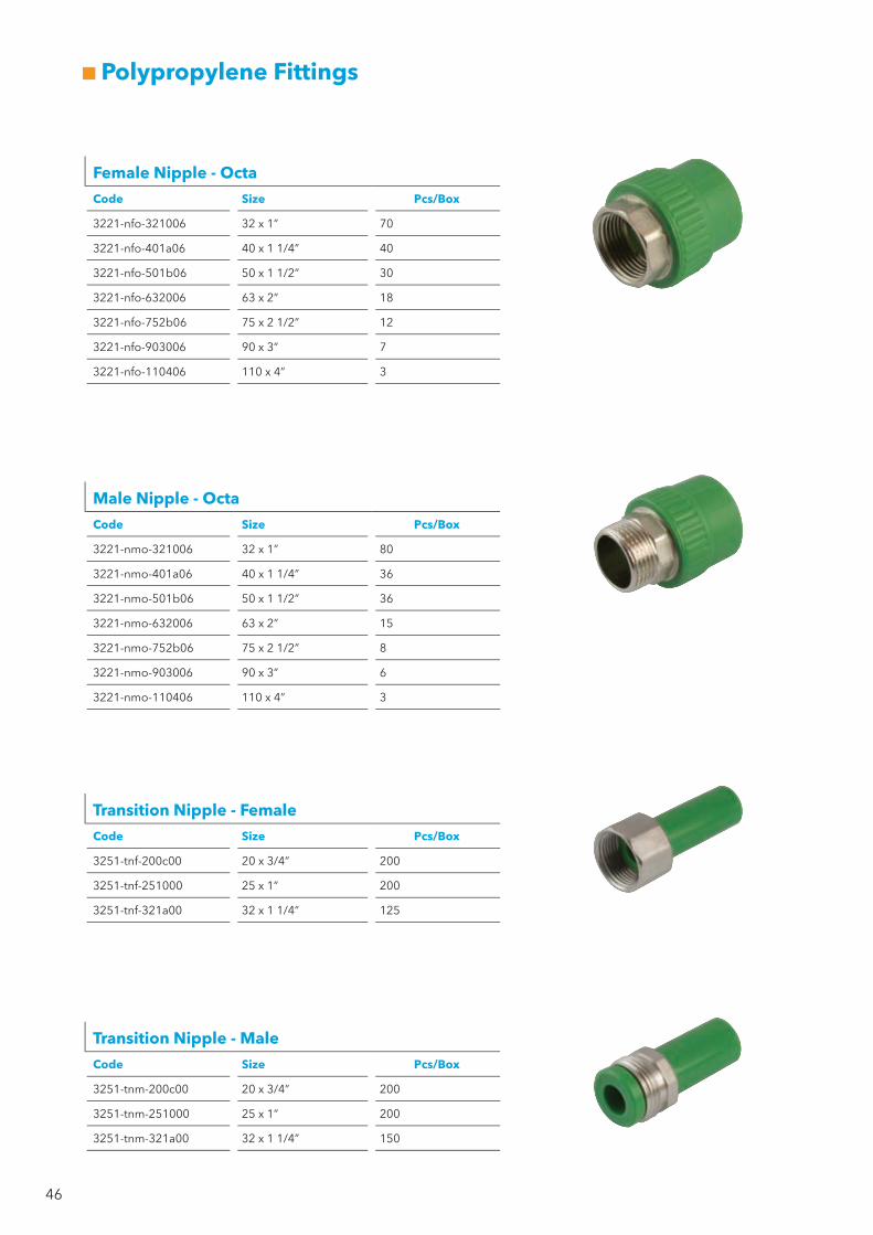
Polypropylene Fittings
Female Nipple - Octa
Code Size Pcs/Box
3221-nfo-321006 32 x 1” 70
3221-nfo-401a06 40 x 1 1/4” 40
3221-nfo-501b06 50 x 1 1/2” 30
3221-nfo-632006 63 x 2” 18
3221-nfo-752b06 75 x 2 1/2” 12
3221-nfo-903006 90 x 3” 7
3221-nfo-110406 110 x 4” 3
Male Nipple - Octa
Code Size Pcs/Box
3221-nmo-321006 32 x 1” 80
3221-nmo-401a06 40 x 1 1/4” 36
3221-nmo-501b06 50 x 1 1/2” 36
3221-nmo-632006 63 x 2” 15
3221-nmo-752b06 75 x 2 1/2” 8
3221-nmo-903006 90 x 3” 6
3221-nmo-110406 110 x 4” 3
Transition Nipple - Female
Code Size Pcs/Box
3251-tnf-200c00 20 x 3/4” 200
3251-tnf-251000 25 x 1” 200
3251-tnf-321a00 32 x 1 1/4” 125
Transition Nipple - Male
Code Size Pcs/Box
3251-tnm-200c00 20 x 3/4” 200
3251-tnm-251000 25 x 1” 200
3251-tnm-321a00 32 x 1 1/4” 150

47
New by
Polypropylene Fittings
Elbow with Loose Nut
Code Size Pcs/Box
3221-tue-200b00 20 x 1/2” 180
3221-tue-200c00 20 x 3/4” 150
3221-tue-250c00 25 x 3/4” 120
3221-tue-251000 25 x 1” 80
3221-tue-321000 32 x 1” 50
3221-tue-321a00 32 x 1 1/4” 40
Nipple with Loose Nut
Code Size Pcs/Box
3221-tun-200b00 20 x 1/2” 210
3221-tun-200c00 20 x 3/4” 210
3221-tun-250c00 25 x 3/4” 150
3221-tun-251000 25 x 1” 80
3221-tun-321000 32 x 1” 80
3221-tun-321a00 32 x 1 1/4” 80
Tee with Loose Nut
Code Size Pcs/Box
3221-tut-200b00 20 x 1/2” x 20 150
3221-tut-200c00 20 x 3/4” x 20 60
3221-tut-250c00 25 x 3/4” x 25 60
3221-tut-251000 25 x 1” x 25 60
3221-tut-321000 32 x 1” x 32 40
3221-tut-321a00 32 x 1 1/4” x 32 30
Check Valve
Code Size Pcs/Box
3221-cvl-0b0000 20 100
3221-cvl-0c0000 25 60

48
Polypropylene Fittings
Filter - Female/Female
Code Size Pcs/Box
3221-flt-200001 20 100
3221-flt-250001 25 60
3221-flt-320001 32 30
Filter - Male/Female
Code Size Pcs/Box
3221-flt-200000 20 100
3221-flt-250000 25 60
3221-flt-320000 32 30
Filter - Sealed Female / Eco
Code Size Pcs/Box
3221-fls-200003 20 100
3221-fls-250003 25 60
Filter - Sealed Male / Eco
Code Size Pcs/Box
3221-fls-200002 20 120
3221-fls-250002 25 75

49
New by
Polypropylene Valves
Ball Valve
Code Size Pcs/Box
3241-vlb-200003 20 60
3241-vlb-250003 25 50
3241-vlb-320003 32 25
3241-vlb-400003 40 15
3241-vlb-500003 50 10
3241-vlb-630003 63 6
3241-vlb-750003 75 5
Ball Valve - Long
Code Size Pcs/Box
3241-vlb-200002 20 40
3241-vlb-250002 25 30
Ball Valve with Female Nipple
Code Size Pcs/Box
3241-vlb-200b04 20 x 1/2” 55
3241-vlb-250c04 25 x 3/4” 45
3241-vlb-321004 32 x 1” 20
Ball Valve with Male Nipple
Code Size Pcs/Box
3241-vlb-200b05 20 x 1/2” 50
3241-vlb-250c05 25 x 3/4” 40
3241-vlb-321005 32 x 1” 20

50
Only by
Polypropylene Valves
Mini Ball Valve - Buterfly
Code Size Pcs/Box
3241-vlm-200001 20 120
3241-vlm-200002 20 120
3241-vlm-250001 25 80
3241-vlm-250002 25 80
3241-vlm-320001 32 40
3241-vlm-320002 32 40
Femail Ball Valve - Hexagonal
Code Size Pcs/Box
3241-vlb-321104 32 × 1” 20
Mini Ball Valve
Code Size Pcs/Box
3241-vlm-200000 20 100
3241-vlm-250000 25 75
3241-vlm-320000 32 35
51
Polypropylene Valves
Only by
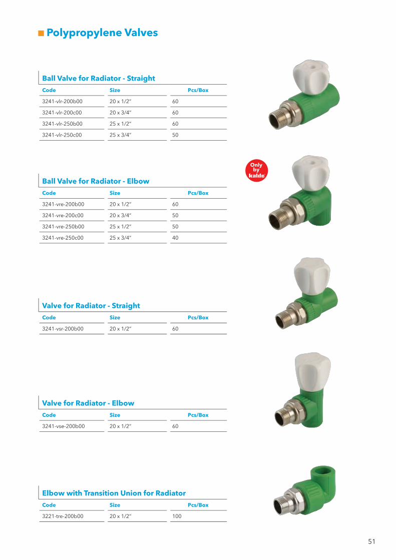
Ball Valve for Radiator - Straight
Code Size Pcs/Box
3241-vlr-200b00 20 x 1/2” 60
3241-vlr-200c00 20 x 3/4” 60
3241-vlr-250b00 25 x 1/2” 60
3241-vlr-250c00 25 x 3/4” 50
Ball Valve for Radiator - Elbow
Code Size Pcs/Box
3241-vre-200b00 20 x 1/2” 60
3241-vre-200c00 20 x 3/4” 50
3241-vre-250b00 25 x 1/2” 50
3241-vre-250c00 25 x 3/4” 40
Valve for Radiator - Straight
Code Size Pcs/Box
3241-vsr-200b00 20 x 1/2” 60
Valve for Radiator - Elbow
Code Size Pcs/Box
3241-vse-200b00 20 x 1/2” 60
Elbow with Transition Union for Radiator
Code Size Pcs/Box
3221-tre-200b00 20 x 1/2” 100
52
Polypropylene Valves
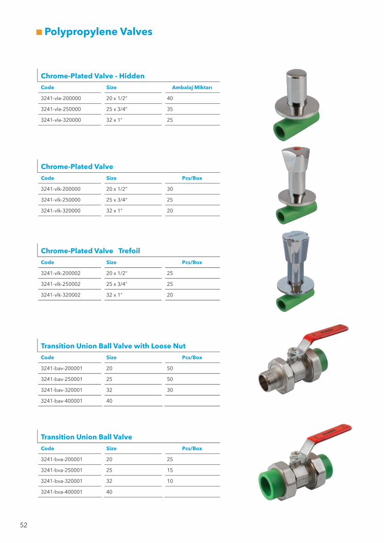
Chrome-Plated Valve
Code Size Pcs/Box
3241-vlk-200000 20 x 1/2” 30
3241-vlk-250000 25 x 3/4” 25
3241-vlk-320000 32 x 1” 20
Chrome-Plated Valve Trefoil
Code Size Pcs/Box
3241-vlk-200002 20 x 1/2" 25
3241-vlk-250002 25 x 3/4" 25
3241-vlk-320002 32 x 1" 20
Chrome-Plated Valve - Hidden
Code Size Ambalaj Miktarı
3241-vle-200000 20 x 1/2” 40
3241-vle-250000 25 x 3/4” 35
3241-vle-320000 32 x 1” 25
Transition Union Ball Valve with Loose Nut
Code Size Pcs/Box
3241-bav-200001 20 50
3241-bav-250001 25 50
3241-bav-320001 32 30
3241-bav-400001 40
Transition Union Ball Valve
Code Size Pcs/Box
3241-bva-200001 20 25
3241-bva-250001 25 15
3241-bva-320001 32 10
3241-bva-400001 40

53
Ball Valve with Single Transtion Union
Code Ölçü / Çap / mm. Pcs/Box
3241-vlb-200006 20 45
3241-vlb-250006 25 35
3241-vlb-320006 32 25
Ball Valve with Double Transtion Union
Code Size Pcs/Box
3241-vlb-200005 20 40
3241-vlb-250005 25 30
3241-vlb-320005 32 20
3241-vlb-400005 40 10
3241-vlb-500005 50 6
Only by
Polypropylene Valves
PP Manifold
Code Size Pcs/Box
931-set-1400220 2 Ağızlı 9
931-set-1400320 3 Ağızlı 6
931-set-1400420 4 Ağızlı 5
931-set-1400520 5 Ağızlı 4
931-set-1400620 6 Ağızlı 3
931-set-1400720 7 Ağızlı 3
931-set-1400820 8 Ağızlı 3
Valve
Code Size Pcs/Box
3241-vlf-200000 20 40
3241-vlf-250000 25 30
3241-vlf-320000 32 20
3241-vlf-400000 40 20
Valve - Laundry
Code Size Pcs/Box
3243-vlc-0b0c00 1/2” x 3/4” 45

54
Polypropylene Fittings
Transition Union - Female
Code Size Pcs/Box
3271-tuf-200b00 20 x 1/2” 200
3271-tuf-250c00 25 x 3/4” 120
3271-tuf-321000 32 x 1” 80
3271-tuf-401a00 40 x 1 1/4” 50
Transition Union - Male
Code Size Pcs/Box
3271-tum-200b00 20 x 1/2” 200
3271-tum-250c00 25 x 3/4” 120
3271-tum-321000 32 x 1” 80
3271-tum-401a00 40 x 1 1/4” 40
3251-tuf-200c00 20 x 3/4” 200
3251-tuf-250b00 25 x 1/2” 120
3251-tuf-251000 25 x 1” 120
3251-tuf-321a00 32 x 1 1/4” 80
3251-tuf-320c00 32 x 3/4” 100
3251-tuf-501b00 50 x 1 1/2” 36
3251-tuf-632000 63 x 2” 14
3251-tuf-752b00 75 x 2 1/2” 12
3251-tuf-903000 90 x 3” 6
3251-tuf-110400 110 x 4” 3
3251-tum-200c00 20 x 3/4” 200
3251-tum-250b00 25 x 1/2” 100
3251-tum-251000 25 x 1” 100
3251-tum-321a00 32 x 1 1/4” 70
3251-tum-320c00 32 x 3/4” 80
3251-tum-501b00 50 x 1 1/2” 30
3251-tum-632000 63 x 2” 14
3251-tum-752b00 75 x 2 1/2” 8
3251-tum-903000 90 x 3” 5
3251-tum-110400 110 x 4” 3

55
Polypropylene Fittings
Coupling with Loose Nut
Code Size Pcs/Box
3251 -mft- 200000 20 150
3251 -mft- 250000 25 90
3251 -mft- 320000 32 60
Flange Set
Code Size Pcs/Box
3221-sls-500000 50 25
3221-sls-630000 63 15
3221-sls-750000 75 10
3221-sls-900000 90 10
3221-sls-110000 110 6
56
Accessories
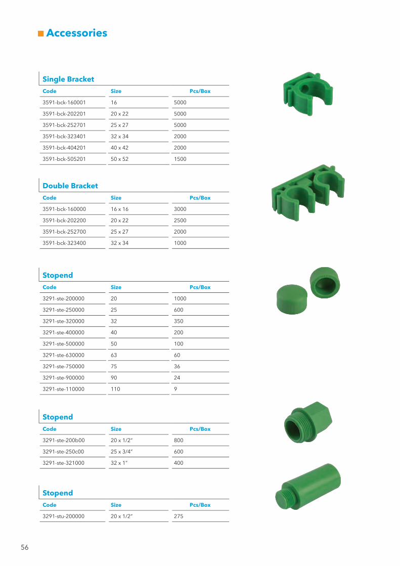
Single Bracket
Code Size Pcs/Box
3591-bck-160001 16 5000
3591-bck-202201 20 x 22 5000
3591-bck-252701 25 x 27 5000
3591-bck-323401 32 x 34 2000
3591-bck-404201 40 x 42 2000
3591-bck-505201 50 x 52 1500
Double Bracket
Code Size Pcs/Box
3591-bck-160000 16 x 16 3000
3591-bck-202200 20 x 22 2500
3591-bck-252700 25 x 27 2000
3591-bck-323400 32 x 34 1000
Stopend
Code Size Pcs/Box
3291-ste-200000 20 1000
3291-ste-250000 25 600
3291-ste-320000 32 350
3291-ste-400000 40 200
3291-ste-500000 50 100
3291-ste-630000 63 60
3291-ste-750000 75 36
3291-ste-900000 90 24
3291-ste-110000 110 9
Stopend
Code Size Pcs/Box
3291-ste-200b00 20 x 1/2” 800
3291-ste-250c00 25 x 3/4” 600
3291-ste-321000 32 x 1” 400
Stopend
Code Size Pcs/Box
3291-stu-200000 20 x 1/2” 275

57
Accessories
Scissors
Code Size Pcs/Box
3592-sss-000002 16 / 42 100
3592-sss-000003 16 / 42 Otomatik 50
Welding Machine
Code Size Pcs/Box
3292-wmh-000001 Standart
3292-wmh-000000 2006 Model 5
Welding Apparatus
Code Size Pcs/Box
3292-die-200000 20 1
3292-die-250000 25 1
3292-die-320000 32 1
3292-die-400000 40 1
3292-die-500000 50 1
3292-die-630000 63 1
3292-die-750000 75 1
3292-die-900000 90 1
3292-die-110000 110 1
Tube Sharpener
Code Size Pcs/Box
3292-shv-202500 20 x 25
3292-shv-324000 32 x 40
3292-shv-506300 50 x 63
3292-shv-759000 75 x 90
58
Kalde Klima Orta Basinc ve Valf Sanayii A.S.’s (“Kalde”) Products are manufactured according to international standards and they particularly conform to the DIN norms. This Limited Warranty provides that, subject to the following limitations, each Kalde Product will be free from defects in material and workmanship and will conform to Kalde's specification for the particular Product. Your exclusive remedy for any defective Product is limited to the repair or replacement of the defective Product within fifty (50) years from the date of purchase. If Kalde is unable to repair or replace, as applicable, a defective Product which is covered by this Limited Warranty, Kalde shall, within a reasonable time refund the purchase price of the Product.
This Limited Warranty covers only those defects that arise as a result of normal use, Kalde shall not be liable for any defects that are caused by the neglect, abuse, misuse or mistreatment by anyone or any entity other than Kalde, including but not limited to, improper installation or testing, user’s flawed designs or specifications, unsatisfactory applications, use in conjunction with incompatible materials, contact with aggressive chemical agents, freezing or overheating of liquids in the product and any other neglect or misuse. This Limited Warranty shall be void if the Product fails to function properly as a result of any force majeure (i.e. earthquakes, flood, fire etc.) This Limited Warranty also specifically excludes failure or damage caused by fire stopping materials, tread sealants, plasticized vinyl products or damage caused by the fault or negligence of anyone other than Kalde, or defects that are caused by any Products that have been altered or modified in any way by a person or entity other than Kalde. Products must be used in accordance with standards, regulations and the applicable standards, failure to adhere to these standards shall void this Limited Warranty. Kalde shall have sole and absolute authority to decide whether the Product is covered under the Limited Warranty.
Kalde shall have a reasonable time to repair or replace a defective Product, after determining that a defective Product exists. Kalde's replacement Product under its Limited Warranty will be manufactured from new and serviceable used parts. Kalde's warranty applies to repaired or replaced Products for the balance of the applicable period of the original warranty or ninety days from the date of shipment of a repaired or replaced Product, whichever is longer. For warranty application the end-user must present the purchase invoice.
Kalde's entire liability for any defective Product shall in no event exceed the purchase price for the defective Product. There are no warranties which extend beyond the face of Kalde’s Limited Warranty. Kalde specifically disclaims all other warranties, express or implied, regarding the Products, including any implied warranties of merchantability, fitness for a particular purpose or satisfactory quality. In no event shall Kade or its third party suppliers be liable for direct, indirect, special, collateral, punitive, incidental or consequential damages, No claim or suit or action shall be brought against Kalde more than one year after the related cause of action has occurred. The foregoing liability limitations are essential elements of this Limited Warranty. No course of dealing or trade usage or course of performance shall be relevant to explain or supplement any term in this Limited Warranty. No addition to or modification of any provision of This Limited Warranty shall be binding upon Kalde unless made in writing and signed by Kalde Klima Orta Basınç ve Valf Sanayii A.Ş. This Limited Warranty shall be governed by and construed under the law of Republic of Turkey, without regard to the conflict of law principles thereof. All disputes arising out of or relating to this Limited Warranty shall be adjudicated at Istanbul Merkez Mahkemeleri, Turkey. Kalde doesn’t provide any warranty to Products sold to U.S. and Canada.
NOTE: Kalde carries a Products Liability Insurance Policy from ERGO AŞ. that provides for EURO 2,000,000 per year to cover any third-party legal liability. For insurance application the internationally approved procedures are required. This Products Liability Insurance Policy does not include the damage claims made in connection with the (direct or indirect) sales made to countries that have been placed an embargo by USA or EU countries (including the OFAC countries). Kalde keeps the right to ask for any supplementary document necessary to approve damage indemnity.
15.1
1.20
17 /
İsta
nbul
-Pro
mat


![Manufactoring Instructions - kutschera-ets.comkutschera-ets.com/files/PDF/Manufactoring Instructions.pdfGeneral tolerances In accordance with DIN ISO 2768-1 Length [mm] Turned and](https://img.dokumen.tips/doc/110x75/5e6bcf50a311b472a74ad19e/manufactoring-instructions-kutschera-etscomkutschera-etscomfilespdfmanufactoring.jpg)