Embed Size (px)
Citation preview

University of Rhode Island University of Rhode Island
DigitalCommons@URI DigitalCommons@URI
PHY 204: Elementary Physics II -- Lecture Notes PHY 204: Elementary Physics II (2021)
10-14-2020
15. Electric current and current density. Resistivity, resistance, and 15. Electric current and current density. Resistivity, resistance, and
resistor resistor
Gerhard Müller University of Rhode Island, [email protected]
Robert Coyne University of Rhode Island, [email protected]
Follow this and additional works at: https://digitalcommons.uri.edu/phy204-lecturenotes
Recommended Citation Recommended Citation Müller, Gerhard and Coyne, Robert, "15. Electric current and current density. Resistivity, resistance, and resistor" (2020). PHY 204: Elementary Physics II -- Lecture Notes. Paper 15. https://digitalcommons.uri.edu/phy204-lecturenotes/15https://digitalcommons.uri.edu/phy204-lecturenotes/15
This Course Material is brought to you for free and open access by the PHY 204: Elementary Physics II (2021) at DigitalCommons@URI. It has been accepted for inclusion in PHY 204: Elementary Physics II -- Lecture Notes by an authorized administrator of DigitalCommons@URI. For more information, please contact [email protected].
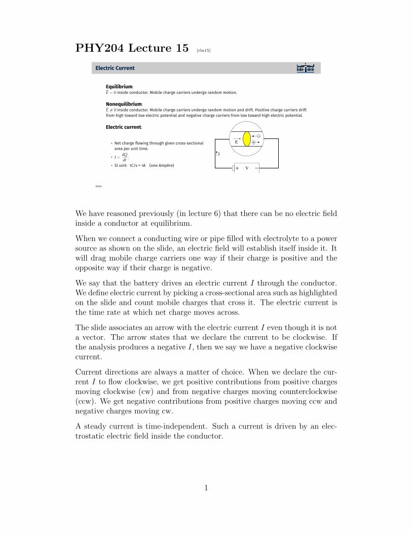
PHY204 Lecture 15 [rln15]
Electric Current
Equilibrium:~E = 0 inside conductor. Mobile charge carriers undergo random motion.
Nonequilibrium:~E 6= 0 inside conductor. Mobile charge carriers undergo random motion and drift. Positive charge carriers driftfrom high toward low electric potential and negative charge carriers from low toward high electric potential.
Electric current:
• Net charge flowing through given cross-sectionalarea per unit time.
• I =dQdt
.
• SI unit: 1C/s = 1A (one Ampere)
+
−
+ −
I
V
E
tsl131
We have reasoned previously (in lecture 6) that there can be no electric fieldinside a conductor at equilibrium.
When we connect a conducting wire or pipe filled with electrolyte to a powersource as shown on the slide, an electric field will establish itself inside it. Itwill drag mobile charge carriers one way if their charge is positive and theopposite way if their charge is negative.
We say that the battery drives an electric current I through the conductor.We define electric current by picking a cross-sectional area such as highlightedon the slide and count mobile charges that cross it. The electric current isthe time rate at which net charge moves across.
The slide associates an arrow with the electric current I even though it is nota vector. The arrow states that we declare the current to be clockwise. Ifthe analysis produces a negative I, then we say we have a negative clockwisecurrent.
Current directions are always a matter of choice. When we declare the cur-rent I to flow clockwise, we get positive contributions from positive chargesmoving clockwise (cw) and from negative charges moving counterclockwise(ccw). We get negative contributions from positive charges moving ccw andnegative charges moving cw.
A steady current is time-independent. Such a current is driven by an elec-trostatic electric field inside the conductor.
1

Current and Current DensityConsider drift of Na+ and Cl− ions in a plastic pipe filled with salt water.
• v1 > 0, v2 < 0: drift velocities [m/s]• q1 > 0, q2 < 0: charge on ions [C]• n1, n2: number of charge carriers per unit volume [m−3]
+
−Cl
AE
v2−
q2
Na+
v1
1q
• Net charge flowing through area A in time dt: dQ = n1q1v1Adt + n2q2v2Adt [C]
• Electric current through area A: I ≡ dQdt
= A(n1q1v1 + n2q2v2) [A]
• Current density:~J = n1q1~v1 + n2q2~v2 [A/m2]
• Current equals flux of current density: I =∫~J · d~A [A]
tsl132
Here we use an electrolyte for a more quantitative discussion of electric cur-rent. Unlike in a metallic conductor, where only negative charge carriers(electrons) are mobile, here we have positively charged sodium ions and neg-atively charged chlorine ions that are both mobile.
The current density ~J is a vector quantity constructed from the velocity vec-tors of the charge carriers as shown. Each type of charge carrier contributesone term. Both terms are vectors pointing to the right even though the Na+
and Cl− ions drift in opposite direction. Multiplying the vector ~v2, whichpoints to the left, with the negative charge q2, produces a vector q2~v2 pointingto the right.
The current I is the flux of the current density ~J through the cross-sectionalsurface area A. Associated with the surface is an area vector ~A, perpendicularto the plane of the surface. We have chosen the area vector to point to theright. This choice declares that I flows from left to right.
We can determine the current directly from the net charge dQ flowing fromleft to right across the surface in time dt as shown on the slide. Av1dt(|Av2dt|) is the volume that contains all positive (negative) charge carriersthat make it through the surface from left to right (right to left) in time dt.
In a metallic conductor, e.g. a copper wire, the expressions for current I andcurrent density ~J only have their second terms, representing electrons driftingfrom right to left. The vector ~J would point to the right nevertheless and,given our choice of area vector ~A, we will have a positive current I flowingfrom left to right.
2

Current Direction
positive charge carriers negative charge carriers
positive current I flowing toward left in both cases
negative current I flowing toward right in both cases
tsl451
Here we wish to drive home two key insights gained on the previous page.The three vectors represent drift velocity ~vd of mobile charge carriers, electricfield ~E, and current density ~J .
(i) Charge carriers do not necessarily move in the direction of the currentdensity. In the case of positive charge carriers (shown on the left), the vectors
~vd and ~J are parallel. However, the two vectors are antiparallel in the caseof negative charge carriers (shown on the right).
Positive and negative charge carriers are in contact with the same electricfield ~E. However, they experience an electric force ~F = q ~E in oppositedirections.
(ii) The direction of current I (not a vector) is a matter of choice. Recallthat current is the flux of current density through a cross-sectional surface,which is an open surface:
I =
∫~J · d ~A.
We have learned earlier (in lecture 4) that for opens surfaces the direction ofarea vectors is a matter of choice.
Choosing an area vector ~A pointing to the left (right) for the situations shownon the slide, means declaring left (right) to be the direction of I. When weadopt the first (second) choice, the current I comes out to positive (negative).
3

Resistance and Resistivity
• Resistor: device (material object with two terminals)• Resistance: attribute of device• Resistivity: attribute of conducting material
A voltage V provided by some source is applied to the terminals of a resistor and a current I is observedflowing through the resistor.
• Resistance: R =VI
[1Ω=1V/A] (1 Ohm)
The current density~J in a resistor depends on the local electric field ~E and on the resistivity ρ of the resistormaterial.
• Resistivity: ρ =EJ
[1V/m1A/m2 = 1Ωm
]
• Conductivity: σ =1ρ
[1(Ωm)−1]
• Vector relations: ~E = ρ~J, ~J = σ~E
tsl134
We must not confuse the similarly sounding terms listed at the top of theslide. In this lecture, we focus on how the terms are related, specifically howattributes of conducting materials are related to functions of devices. Thenext three lectures (lectures 16, 17, and 18) will then all be on how devicesfunction in circuits.
On the material level, we work with the quantities ~J (current density), ~E(electric field), ρ (resistivity), and σ (conductivity).
On the device level, we use different quantities: V (voltage), I (current), andR (resistance).
4

Resistivity of Materials
• α =(ρ − ρ20)/ρ20
tC − 20C• α: temperature coefficient
at 20C in K−1
• ρ: resistivity near 20C• ρ20: resistivity at 20C• tC: temperature in C
tsl139
The list of materials is naturally divided into three groups with their resis-tivity ρ orders of magnitude apart.
The first group of nine are conductors, the second group of two are semicon-ductors, and the remaining five are insulators.
In general, the resistivity of a material varies with temperature. The tem-perature coefficient α gives a measure for how much ρ changes per degree ofdeviation from room temperature.
In metallic conductors, the resistivity typically increases with temperature.Here the cause of resistivity are scattering events between the mobile elec-trons and the localized ions. The amplitudes of lattice vibrations, whichincrease with temperature, enhance the scattering probabilities.
In semiconductors, by contrast, the resistivity decreases with temperature.Here, the mobility of charge carriers is of a different kind. No electrons havethe mobility of conduction electrons. All electrons are bound, but some areloosely bound, such that they can hop from atom to atom when pulled by theforce of an electric field. The hopping is enhanced by the lattice vibrations,as if thermal energy shakes them loose.
5

Ohm’s Law
V = RI with R = const
satisfied violated
tsl452
The main point of this slide is for us to appreciate the distinction betweena linear and a nonlinear device, specifically, a device that obeys Ohm’s lawand one that does not.
The resistor (shown on the left) and the capacitor (not shown) are lineardevices. The diode (shown on the right) is a nonlinear device.
The linear relation, V = RI, between voltage and current is shown in thediagram on the left. It represents Ohm’s law. Likewise, characteristic of acapacitor is the linear relation, Q = CV , between charge and voltage.
The diode permits large currents in the forward direction when driven byvoltages V > 0, but almost no current when driven in the opposite directionby voltages V < 0. This is illustrated in the diagram on the right. Thecurrent-voltage characteristic is nonlinear.
Diodes are realized in vacuum tubes and in semiconductor devices.
6

Calculating the Resistance of a Wire
Uniform cross section• Length of wire: L
• Area of cross section: A
• Resistivity of material: ρ
• Current density: J =Eρ
[A/m2]
• Current: I = JA [A]
• Voltage: V = EL [V]
• Resistance: R ≡ VI=
ρLA
[Ω]
Variable cross section• Cross-sectional profile: A(x)
• Resistance of slice: dR =ρdx
A(x)
• Resistance of wire: R = ρ∫ L
0
dxA(x)
dx
x
x L
A
tsl136
In lecture 12 we calculated the capacitance for capacitors of different designs.Here we calculate the resistance of resistors, starting with the most commonshape: a wire of some length and cross-sectional area, made of a particularconducting material.
The itemized list on the left spells out how we assemble the various ingre-dients using relations introduced earlier into an expression for resistance,defined as R = V/I.
Resistance means resistance to current at given voltage. It increases if theresistor is made longer or thinner or if a material of higher resistivity is used.
When the resistor has a variable cross section, as shown on the right, wegeneralize this result by employing it in a creative way. We anticipate aresult derived later (in the context of resistor circuits) that the resistance ofresistors connected in series is the sum of individual resistances.
In the present context, we divide the wire of variable cross section into in-finitesimal slices. They are connected in series. We add up the resistancesof all slices, for which we use the result from the left side with L replaced bydx and with the constant cross-sectional area A replaced by a function A(x).This amounts to performing n integral as shown.
The same scheme can be used if we have a wire with variable resistivity ρ(x).
7

Radial Current in Coaxial Cable
dR =ρdrA
, A = 2πrL
R =ρ
2πL
∫ b
a
drr
=ρ
2πLln
ba
tsl453
Consider a coaxial cable with an inner and an outer layer of materials withlow resistivity ρL. They are separated by a layer of a material with muchhigher resistivity ρH.
A coaxial cable in use typically has the two highly conducting layers atdifferent electric potential with currents moving in opposite directions alongthe cable.
Here we are interested in the current that leaks through the more resistivelayer in radial direction. For that purpose we need to calculate the resistanceof a cylindrical shell of length L with terminals at radii a and b.
We adopt the method introduced on the previous page. Instead of thin flatslices we have thin cylindrical shells. Each shell has resistance dR as shown.They are connected in series again. We can add their resistances via anintegral.
For a radial current in a coaxial cable, the resistance R⊥ is inversely pro-portional to the length L length, whereas for a current along the cable theresistance R‖ is proportional L. Leakage prevention requires that R⊥ is highcompared to R‖.
8

Electric Current Application (1)
A steady current I is flowing through a wire from left to right. The wire first doubles its diameter and thensplits into two wires of the original diameter. Both branches on the right carry the same current.
2cm 4cm
2cm
2cm
I1
I2
I3
I4
Rank the current densities J1, J2, J3 = J4 in the three segments.
tsl133
The point of this slide is to sharpen our understanding of current and currentdensity.
Here we have a wire of uniform resistivity that first gets wider and thensplits into to branches of equal width. How do the current I and the currentdensity J change from position 1 on the left to position 2 in the middle andpositions 3,4 on the right?
The current is steady. No charge accumulates anywhere. Therefore, thecurrent does not change between positions 1 and 2. Between positions 2 and3,4 it splits into two equal part:
I2 = I1, I3 = I4 =1
2I2.
Given that the cross-sectional area quadruples between positions 1 and 2, weconclude that the current density (current per unit area) decreases by a factorfour. Between positions 2 and 3,4 the total cross-sectional area decreases tohalf its value for the same total current. This implies that the current densitydoubles:
J2 =1
2J1, J3 = J4 = 2J2.
9

Electric Current Application (3)
Consider three wires made of the same material.
Wire 1 of length 2m and diameter 2mm has a resistance 18Ω.
(a) What resistance does wire 2 of length 4m and diameter 4mm have?(b) How long is wire 3 of diameter 6mm with a resistance of 18Ω?
tsl147
The only resource we need for this exercise is the familiar expression for theresistance of a wire: R = ρL/A.
For wire 1 we write,
R1 =ρL1
A1
= 18Ω.
For wire 2 with twice the length and twice the diameter we write,
L2 = 2L1, A2 = 4A1 ⇒ R2 =ρ(2L1)
4A1
=1
2R1 = 9Ω.
For wire 3 with three times the diameter of wire 1 and equal resistance, wewrite,
A3 = 9A1, R3 =ρL3
9A1
=ρL1
A1
= 18Ω ⇒ L3 = 9L1 = 18m.
10

Electric Current Application (2)
Two wires are formed into
(a) an equilateral triangle,(b) a regular pentagon.
A voltage between points 1 and 2 produces a current of 12mA along the shorter path.
12mA
12mA
(a)(b)
1 2
1 2
What is the current along the longer path in each case?
tsl137
This is the quiz for lecture 15.
11


