Embed Size (px)
Citation preview
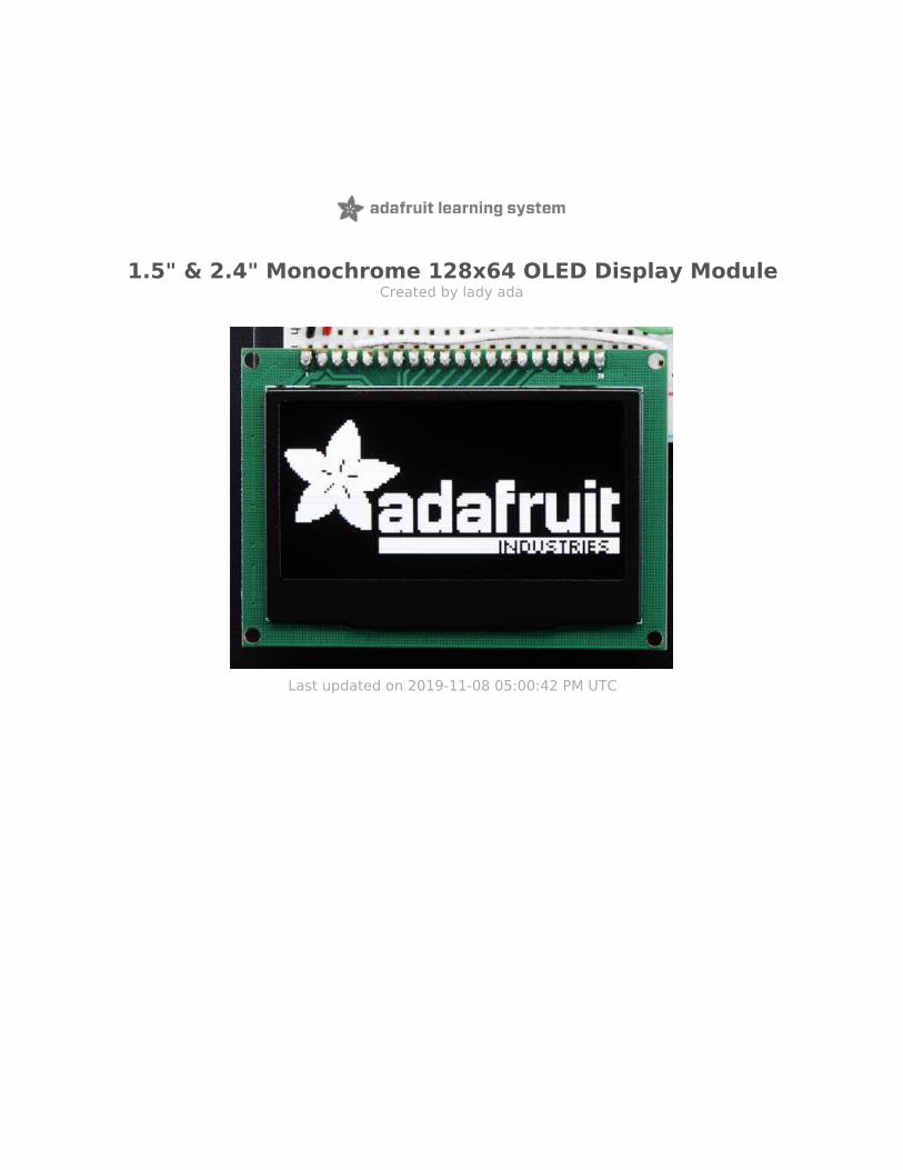
1.5" & 2.4" Monochrome 128x64 OLED Display ModuleCreated by lady ada
Last updated on 2019-11-08 05:00:42 PM UTC

Overview
If you've been diggin' our monochome OLEDs (https://adafru.it/eau) but need something bigger, this display will delightyou! These displays are 1.5" and 2.4" diagonal, and very readable due to the high contrast of an OLED display. Thisdisplay is made of 128x64 individual white OLED pixels, each one turned on or off by the controller chip. Because thedisplay makes its own light, no backlight is required. This reduces the power required to run the OLED and is why thedisplay has such high contrast; we really like this graphic display for its crispness!
© Adafruit Industries https://learn.adafruit.com/1-5-and-2-1-monochrome-128x64-oled-display-module Page 3 of 22

The driver chip, SSD1305 can communicate in three ways: 8-bit, I2C or SPI. Personally we think SPI is the way to go,only 4 or 5 wires are required and its very fast. The OLED itself requires a 3.3V power supply and 3.3V logic levels forcommunication. We include a breadboard-friendly level shifter that can convert 3V or 5V down to 3V, so it can be usedwith 5V-logic devices like Arduino.
The power requirements depend a little on how much of the display is lit but on average the display uses about 50mAfrom the 3.3V supply. Built into the OLED driver is a simple switch-cap charge pump that turns 3.3V into a high voltagedrive for the OLEDs.
Each order comes with one assembled OLED module with a nice bezel and 4 mounting holes. The display is 3V logic& power so we include a HC4050 level shifter. We also toss in a 220uF capacitor, as we noticed an Arduino may needa little more capacitance on the 3.3V power supply for this big display! This display does not come with headerattached but we do toss in a stick of header you can solder on. Also, the display may come in 8-bit mode. You canchange modes from 8-bit to SPI or I2C with a little soldering, check out the Assembly page for how to do so.
© Adafruit Industries https://learn.adafruit.com/1-5-and-2-1-monochrome-128x64-oled-display-module Page 4 of 22

Getting started is easy! We have a detailed tutorial and example code in the form of an Arduino library for text andgraphics. You'll need a microcontroller with more than 512 bytes of RAM since the display must be buffered. The librarycan print text, bitmaps, pixels, rectangles, circles and lines. It uses 512 bytes of RAM since it needs to buffer the entiredisplay but its very fast! The code is simple to adapt to any other microcontroller.
© Adafruit Industries https://learn.adafruit.com/1-5-and-2-1-monochrome-128x64-oled-display-module Page 5 of 22

Pinouts
The pins on these modules are not well marked, but the one on left is #1 and the pins increment in order until the oneon the very right, #20
Power Pins
Pin #1 is power and signal GroundPin #2 is 3V Power In - provide 3V with 50-75mA current capabilityPin #3 is not used, do not connect to anything
Signal Pins
Pin #4 is DC - the data/command pin. This is a 3V logic level input pin and is used for both SPI and 8-bitconnectionsPin #5 is WR - the 8-bit write pin. This is a 3V logic level input pin and is used for 8-bit connections. Do notconnect if using SPI/I2CPin #6 is RD - the 8-bit read pin. This is a 3V logic level input pin and is used for 8-bit connections. Do notconnect if using SPI/I2CPin #7 is Data0 - this pin is the SPI Clock pin, I2C Clock pin and the 8-bit data bit 0 pin. This is a 3V logic levelinput pin when used with I2C/SPI, and an input/output when used in 8-bit.Pin #8 is Data1 - this pin is the SPI Data In pin, I2C Data pin and the 8-bit data bit 1 pin. This is a 3V logic levelinput pin when used with I2C/SPI, and an input/output when used in 8-bit.Pins #9-14 are Data2-7 - Used for 8-bit mode. These is a 3V input/output when used in 8-bit. Do not connect ifusing SPI or I2CPin #15 is CS - the chip select pin. This is a 3V logic level input pin and is used for both SPI and 8-bit connectionsPin #16 is RESET - the reset pin. This is a 3V logic level input pin and is used for I2C, SPI and 8-bit connections
Remaining Pins
Pins #17-19 are not connected, do not usePin #20 is the 'frame ground' pin and is connected to the metal case around the OLED, you can connect to
© Adafruit Industries https://learn.adafruit.com/1-5-and-2-1-monochrome-128x64-oled-display-module Page 6 of 22

ground or leave floating.
© Adafruit Industries https://learn.adafruit.com/1-5-and-2-1-monochrome-128x64-oled-display-module Page 7 of 22

Assembly
Changing "modes"
These modules can be used in SPI or 8-Bit mode. Somewhat annoyingly, the only way to switch modes is todesolder/solder jumpers on the back of the modules.
SPI Mode
This is the mode you likely want to be in. Your module may have come with this setting by default.
On the 1.5" OLED module: Make sure the R12 and R10 resistors are soldered in and the R11 and R9 spots are blank
On the 2.4" OLED module: Make sure the R19 and R21 resistors are soldered in and the R18 and R20 spots are blank
I2C mode
On the 1.5" OLED module: Make sure the R12 and R9 resistors are soldered in and the R11 and R10 spots are blank
© Adafruit Industries https://learn.adafruit.com/1-5-and-2-1-monochrome-128x64-oled-display-module Page 8 of 22

On the 2.4" OLED module: Make sure the R18 and R21 resistors are soldered in and the R19 and R20 spots are blank
8-Bit "6800" mode
This mode uses 8 pins + 4 or 5 control pins. We dont have support code for it but you could modify the library if youlike to add it. Check the datasheet for more details!
On the 1.5" OLED module: Make sure the R11 and R10 resistors are soldered in and the R12 and R9 spots are blank
On the 2.4" OLED module: Make sure the R19 and R20 resistors are soldered in and the R18 and R21 spots are blank
© Adafruit Industries https://learn.adafruit.com/1-5-and-2-1-monochrome-128x64-oled-display-module Page 9 of 22

Wiring &Test
We will demonstrate using this display with an Arduino UNO compatible. If you are using a 3V logic device you canskip the level shifter and connect direct from the microcontroller to display. You can also use another kind of levelshifter if you like.
Any microcontroller with I2C + 1 pin or 4 or 5 pins can be used, but we recommend testing it out with an UNO beforeyou try a different processor.
SPI Wiring
Since this is a SPI-capable display, we can use hardware or 'software' SPI. To make wiring identical on all Arduinos,we'll begin with 'software' SPI. The following pins should be used:
Connect Pin #1 to common power/data ground line (black wires)Connect Pin #2 to the 3V power supply on your Arduino. (red wires)Skip pin #3
Don't forget you have to set the display to SPI mode, see the Assembly step on how to do that!�
© Adafruit Industries https://learn.adafruit.com/1-5-and-2-1-monochrome-128x64-oled-display-module Page 10 of 22

Connect Pin #4 (DC) to digital #8 via the level shifter (white wires) any pin can be used laterConnect Pin #7 (SCLK) to digital #13 via the level shifter (blue wires) any pin can be used laterConnect Pin #8 (DIN) to digital #11 via the level shifter (green wires) any pin can be used laterSkip pins #9-14Connect Pin #15 (CS) to digital #10 via the level shifter (yellow wires) any pin can be used laterConnect Pin #16 (RST) to digital #9 via the level shifter (orange wires) any pin can be used later
Later on, once we get it working, we can adjust the library to use hardware SPI if you desire, or change the pins to anyothers.
Level Shifter Wiring
You will also want to power the HC4050 level shifter by connecting pin #1 to 3V (the red wire) and pin #8 to ground(the black wire)
3.3V Capacitor
We also include a 220uF capacitor with your order because we noticed that the 3V line can fluctuate a lot whenpowered via an Arduino's 3.3V regulator. We really recommend installing it. Clip the leads on this capacitor andconnect the negatve pin to GND and the positive pin to 3V
Download Adafruit_SSD1305 library
To begin reading sensor data, you will need to download Adafruit_SSD1305 (https://adafru.it/fLd) from our githubrepository. You can do that by visiting the github repo and manually downloading or, easier, just click this button todownload the zip
https://adafru.it/fLe
https://adafru.it/fLe
Rename the uncompressed folder Adafruit_SSD1305 and check that the Adafruit_SSD1305 folder containsAdafruit_SSD1305.cpp and Adafruit_SSD1305.h
Place the Adafruit_SSD1305 library folder your arduinosketchfolder/libraries/ folder. You may need to create thelibraries subfolder if its your first library. Restart the IDE.
We also have a great tutorial on Arduino library installation at: http://learn.adafruit.com/adafruit-all-about-arduino-libraries-install-use (https://adafru.it/aYM)
Installing Adafruit_GFX
You'll also need to download the 'underlying' graphics support library that does all the lines, text, rectangle drawing foryou. You can grab it from https://github.com/adafruit/Adafruit-GFX-Library (https://adafru.it/yCb)
Or click on the button below and follow the same instructions you did for the Adafruit_SSD1305 library. Uncompressand rename the folder to Adafruit_GFX (contains Adafruit_GFX.cpp and .h). Then place them inside your Arduinolibraries folder and restart the Arduino IDE. If this is all unfamiliar, we have a tutorial introducing Arduino libraryconcepts and installation (https://adafru.it/aYM).
https://adafru.it/cBB
https://adafru.it/cBB
© Adafruit Industries https://learn.adafruit.com/1-5-and-2-1-monochrome-128x64-oled-display-module Page 11 of 22

Restart the IDE!
Adjust display size
Before you compile and run the demo, you'll need to make sure you have the library configured to the right size. Openup the Adafruit_SSD1305.h file in your ArduinoSketchFolder/libraries/Adafruit_SSD1305 folder and look for the linesthat have:
#define SSD1305_128_32//#define SSD1305_128_64
If you are running a 128x32 display, leave the second line commented
If you are running a 128x64 size display, comment the first line and uncomment the second one. Then save the file
Running the Demo
After restarting the Arduino software, you should see a new example folder called Adafruit_SSD1305 and inside, anexample called ssd1305test
Now upload the sketch to your Arduino. That's pretty much it! You should see immediate update of the display.
If nothing shows up at all, make sure you have your wiring correct, we have a diagram above you can use. Also, checkthat you converted the module to "SPI" mode (see the Assembly) step on how to do that
Changing Pins
Now that you have it working, there's a few things you can do to change around the pins.
If you're using Hardware SPI, the CLOCK and MOSI pins are 'fixed' and cant be changed. But you can change to
© Adafruit Industries https://learn.adafruit.com/1-5-and-2-1-monochrome-128x64-oled-display-module Page 12 of 22

software SPI, which is a bit slower, and that lets you pick any pins you like. Find these lines:
// If using software SPI, define CLK and MOSI#define OLED_CLK 13#define OLED_MOSI 11
// These are neede for both hardware & softare SPI#define OLED_CS 10#define OLED_RESET 9#define OLED_DC 8
Change those to whatever you like!
Using Hardware SPI
If you want a little more speed, you can 'upgrade' to Hardware SPI. Its a bit faster, maybe 2x faster to draw but requiresyou to use the hardware SPI pins.
SPI CLK connects to SPI clock. On Arduino Uno/Duemilanove/328-based, thats Digital 13. On Mega's, its Digital52 and on Leonardo/Due its ICSP-3 (See SPI Connections for more details (https://adafru.it/d5h))SPI DATA IN connects to SPI MOSI. On Arduino Uno/Duemilanove/328-based, thats Digital 11. On Mega's, itsDigital 51 and on Leonardo/Due its ICSP-4 (See SPI Connections for more details (https://adafru.it/d5h))
To enable hardware SPI, look for these lines:
// this is software SPI, slower but any pinsAdafruit_SSD1305 display(OLED_MOSI, OLED_CLK, OLED_DC, OLED_RESET, OLED_CS);
// this is for hardware SPI, fast! but fixed oubs//Adafruit_SSD1305 display(OLED_DC, OLED_RESET, OLED_CS);
Comment out the top line and uncomment the bottom line
I2C Wiring
It is also possible to use the display in I2C mode. Its a little slower but uses way fewer pins.
© Adafruit Industries https://learn.adafruit.com/1-5-and-2-1-monochrome-128x64-oled-display-module Page 13 of 22

For I2C you will need to use the hardware I2C pins on your Arduino or microcontroller. The following pins should beused:
Connect Pin #1 to common power/data ground line (black wires)Connect Pin #2 to the 3V power supply on your Arduino. (red wires)Skip pin #3Connect Pin #4 (DC & I2C Addr0) to ground (black wire) to set the I2C address to 0x3C. If this is tied to 3.3V, itwill set the I2C address to 0x3DConnect Pin #7 (SCL) to Arduino SCL (green wire)Connect 10K resistor from SCL to 3.3VConnect Pin #8 (SDA) to Arduino SDA (blue wire)Connect 10K resistor from SDA to 3.3VConnect Pin #9 (SDA2) to Pin #8 (small blue wire)Skip pins #9-15Connect Pin #16 (RST) to digital #9 by using a resistive divider as shown, two resistors from 1K to 10K both thesame value can be used. Any pin can be used later
While its ideal to use level shifters on the I2C pins, you can sorta get away with this on an arduino, because the I2Cpins are open collector and there are very weak pullups on those two lines. If using with other I2C devices, we suggestusing a 3V-logic arduino or an I2C-safe shifter. (http://adafru.it/757)
Later on, once we get it working, we can adjust the library to use hardware SPI if you desire, or change the pins to any
Don't forget you have to set the display to I2C mode, see the Assembly step on how to do that!�Unless you are using a Metro 328 you will need to add I2C pullups on SDA and SCL! Use two 10K (or so) resistors, each one connected from SDA & SCL to 3.3V�
© Adafruit Industries https://learn.adafruit.com/1-5-and-2-1-monochrome-128x64-oled-display-module Page 14 of 22

others.
3.3V Capacitor
We also include a 220uF capacitor with your order because we noticed that the 3V line can fluctuate a lot whenpowered via an Arduino's 3.3V regulator. We really recommend installing it. Clip the leads on this capacitor andconnect the negatve pin to GND and the positive pin to 3V
I2C code changes
In the test code, change the top area where you define the protocol used by commenting out the software andhardware SPI and uncommenting the I2C version
// software SPI//Adafruit_SSD1305 display(OLED_MOSI, OLED_CLK, OLED_DC, OLED_RESET, OLED_CS);// hardware SPI//Adafruit_SSD1305 display(OLED_DC, OLED_RESET, OLED_CS);// I2CAdafruit_SSD1305 display(OLED_RESET);
Everything else about the display is identical to SPI mode.
By default we use I2C address 0x3C which is what we get by connecting DC/A0 to ground. If you tie that pin to 3.3Vinstead, the address will be 0x3D and all you have to do is call display.begin(0x3D) to initialize with that address.
© Adafruit Industries https://learn.adafruit.com/1-5-and-2-1-monochrome-128x64-oled-display-module Page 15 of 22

Using Adafruit GFX
The Adafruit_GFX library for Arduino provides a common syntax and set of graphics functions for all of our TFT, LCDand OLED displays. This allows Arduino sketches to easily be adapted between display types with minimal fuss…andany new features, performance improvements and bug fixes will immediately apply across our complete offering ofdisplays.
The GFX library is what lets you draw points, lines, rectangles, round-rects, triangles, text, etc.
Check out our detailed tutorial here http://learn.adafruit.com/adafruit-gfx-graphics-library (https://adafru.it/aPx) It coversthe latest and greatest of the GFX library!
https://adafru.it/jc1
https://adafru.it/jc1
Since this is a 'buffered' display, dont forget to call the "display()" object function whenever you want to update the OLED. The entire display is drawn in one data burst, so this way you can put down a bunch of graphics and display it all at once.
�
© Adafruit Industries https://learn.adafruit.com/1-5-and-2-1-monochrome-128x64-oled-display-module Page 16 of 22

�
F.A.Q.
How come sometimes I see banding or dim areas on the OLED?
These OLEDs are passively drawn, which means that each line is lit at once. These displays are fairly inexpensiveand simple, but as a tradeoff the built in boost converter has to drive all the OLED pixels at once. If you have a linewith almost all the pixels lit it wont be as bright as a line with only 50% or less lit up.
© Adafruit Industries https://learn.adafruit.com/1-5-and-2-1-monochrome-128x64-oled-display-module Page 17 of 22

� The display works, because I can see the splash screen, but when I draw to the display nothingappears!
Don't forget you must call .display() to actually write the display data to the display. Unlike many of our TFTs, theentire display must be written at once so you should print all your text and draw all your squares, then call display()
© Adafruit Industries https://learn.adafruit.com/1-5-and-2-1-monochrome-128x64-oled-display-module Page 18 of 22

� How do I get rid of the splash screen?
Open up Adafruit_SSD1305.cpp in the libraries/Adafruit_SSD1305 folder and find these lines
© Adafruit Industries https://learn.adafruit.com/1-5-and-2-1-monochrome-128x64-oled-display-module Page 19 of 22

static uint8_t buffer[SSD1305_LCDHEIGHT * SSD1305_LCDWIDTH / 8] = {0x00, 0x00, 0x00, 0x00, 0x00, 0x00, 0x00, 0x00, 0x00, 0x00, 0x00, 0x00, 0x00, 0x00, 0x00, 0x00,....0x00, 0x01, 0x00, 0x01, 0x00, 0x00, 0x00, 0x01, 0x00, 0x00, 0x00, 0x01, 0x01, 0x01, 0x01, 0x01};
and delete everything after static uint8_t buffer[SSD1305_LCDHEIGHT * SSD1305_LCDWIDTH / 8] = {and before };
© Adafruit Industries https://learn.adafruit.com/1-5-and-2-1-monochrome-128x64-oled-display-module Page 20 of 22

Downloads
Datasheets
Datasheet for the SSD1305, the passive OLED driver chip in the modules. (https://adafru.it/fLg) This is the chip inthe module that converts I2C/SPI/8-bit commands to OLED control signalsDiagram for 2.42" OLED submodule (https://adafru.it/Cge)Datasheet for the 2.42" OLED display (https://adafru.it/jbY)Diagram for 1.54 OLED submodule (https://adafru.it/jbZ)Datasheet for the 1.54" OLED display (https://adafru.it/Cgf)
Dimentional details for the 1.5" OLED module (dont have one yet for the 2.4" OLED)
© Adafruit Industries https://learn.adafruit.com/1-5-and-2-1-monochrome-128x64-oled-display-module Page 21 of 22

© Adafruit Industries Last Updated: 2019-11-08 05:00:42 PM UTC Page 22 of 22