Embed Size (px)
Citation preview

Part.No..14481.Rev..Awww.insinkerator.com/foodservice
Please.be.certain.that.the.person.who.installs.or.uses.this.appliance.carefully.reads.and.understands.the.Safety.Instructions.contained.in.this.manual.
The.Danger.signal.indicates.an.immediately.hazardous.situation.which,.if.not.avoided,.will result.in.death.or.serious.injury.
The.Warning.signal.alerts.you.to.potential.hazards.or.unsafe.practices.which,.if.not.avoided,.could result.in.severe.personal.injury.or.death.
The.Caution.signal.alerts.you.to.hazards.of.unsafe.practices.which,.if.not.avoided,.may.result.in.minor.personal.injury.or.property.damage.

3
Warranty...........................................................................................................4
Introduction/Typical Installation. Introduction.......................................................................................4. Typical.Installation.............................................................................4
Waste Xpress Features...................................................................................5
WX-101A Control Features/Mounting Control Center. Introduction.......................................................................................6. Typical.Installation.............................................................................6
Installing Disposer..........................................................................................7
InSinkErator Mounting Assemblies. Standard.Mounting...........................................................................8. Special.Mounting..............................................................................8
Installing Waste Xpress. Waste.Xpress.Diagrams....................................................................9. Installing.Waste.Xpress.................................................................. .10. Electrical.Connections................................................................... .10
Plumbing Connections. Waste.Inlet.Line.............................................................................. .11.. Reverse.Auger.Screen.................................................................... .11. Change.Waste.Inlet........................................................................ .11. Waste.Outlet.Line........................................................................... .12. Plumbing.Connections................................................................... .12. Water.Supply.Connection.............................................................. .12. Routing.Water.Flow........................................................................ .12
Electrical Connections................................................................................ .13
Operating Instructions. Pre-Operating................................................................................. .14. Operating.Instruction...................................................................... .15. Operating.Waste.Xpress.System................................................... .16. Operational.Tips............................................................................. .16
Cleaning Instruction.................................................................................... .17
Troubleshooting. System.Troubleshooting................................................................. .18. Disposer.Troubleshooting...............................................................21. Waste.Xpress.Troubleshooting........................................................22
Wiring Diagrams. Model.No..WX-101A-3.(208/230V,.3.phase)....................................24. Model.No..WX-101A-4.(380/460V,.3.phase)....................................26
Motor Wiring Diagram..................................................................................28
Table of Contents

Introduction/Typical Installation
4
INTRODUCTIONThe.InSinkErator®.Waste.Xpress®.is.a.Foodservicekitchen.waste.reduction.system.that.utilizes.a.standardFoodservice.disposer.in.line.with.the.Waste.Xpress..dewatering.system..The.kitchen.waste.is.ground.through.the.disposer.then.transferred.to.the.Waste.Xpress.where.it.is.compressed..After.the.waste.is..compressed,.the.liquids.are.sent.down.the.drain.line.and.the.solid.waste.exiting.the.Waste.Xpress.is.85%.less.in.volume.(see.Figure.1.for.typical.installation).
Important.–.These.installation.instructions.are.forthe.benefit.of.the.installing.contractor..InSinkEratorand/or.InSinkErator.Factory.Authorized.ServiceCenters.do.not.make.original.installations..For.technicalinformation.not.covered.in.these.instructions,contact.the.supplier,.an.InSinkErator.Field.SalesRepresentative,.or.InSinkErator.Foodservice.Salesand.Service.at.1-800-845-8345.
TYPICAL INSTALLATIONA.typical.Waste.Xpress.installation.incorporates.thefollowing.connections.(see.Figure.1):
•.Waste.Xpress
•.Disposer
•.Control.Center
•.Syphon.breaker
•.Solenoid.valves.(2)
•.Water.shut.off.valve
•.Bowl.or.trough
•.Flow.control.valve
•.Cold.water.(sink.or.trough)
•.Hot.water.(Waste.Xpress)
Figure 1. Typical Installation
WASTE XPRESS SYSTEM LIMITED WARRANTY
The.InSinkErator®.Waste.Xpress®,.disposer.and.control.centers.are.warranted.against.defects.in.material.and.workmanship.for.one.year.from.the.date.of.installation..The.warranty.includes.parts.and.labor,.provided.an..InSinkErator.Factory.Authorized.Service.Center.performs.the.service..This.warranty.does.not.apply.if.the.failure..is.due.to:.faulty.or.improper.electrical.installation,.faulty.or.improper.plumbing.installation,.product.abuse.or..misuse,.accidental.damage,.clogged.drain.lines,.improperly.sized.unit.(as.specified.by.InSinkErator).
Warranty
Flow Control Valve
Disposer
Sink Bowl
Syphon Breaker
Cold Water Solenoid Hot Water Solenoid Waste Xpress
Shut Off Valve(supplied by others)
WX-101A Controller
10 max(3.1 m max)
1-1/2" min(38.1 mm
min)1" min
(25.4 mm min)
5
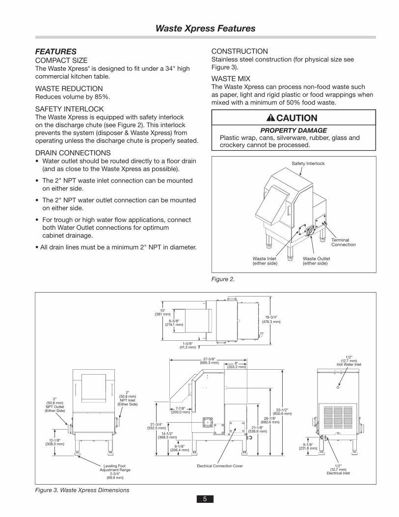
FEATURESCOMPACT.SIZEThe.Waste.Xpress®.is.designed.to.fit.under.a.34".highcommercial.kitchen.table.
WASTE.REDUCTIONReduces.volume.by.85%.
SAFETY.INTERLOCKThe.Waste.Xpress.is.equipped.with.safety.interlock..on.the.discharge.chute.(see.Figure.2)..This.interlock..prevents.the.system.(disposer.&.Waste.Xpress).from.operating.unless.the.discharge.chute.is.properly.seated.
DRAIN.CONNECTIONS•..Water.outlet.should.be.routed.directly.to.a.floor.drain. (and.as.close.to.the.Waste.Xpress.as.possible).
•..The.2".NPT.waste.inlet.connection.can.be.mounted. on.either.side.
•..The.2".NPT.water.outlet.connection.can.be.mounted. on.either.side.
•..For.trough.or.high.water.flow.applications,.connect... both.Water.Outlet.connections.for.optimum... cabinet.drainage.
•.All.drain.lines.must.be.a.minimum.2".NPT.in.diameter.
PROPERTY DAMAGEPlastic.wrap,.cans,.silverware,.rubber,.glass.and.crockery.cannot.be.processed.
Safety Interlock
Water Outlet(either side)Waste Inlet
Terminal Connection
Figure 2.
21-3/4"(552.5 mm) 21-1/8"
(536.6 mm)
26-7/8"(682.6 mm)
33-1/2"(850.9 mm)
8"(203.2 mm)
27-3/8"(695.3 mm)
7-7/8"(200.0 mm)
Electrical Connection Cover
14-1/2"(368.3 mm)
8-1/8"(206.4 mm)
15"(381 mm)
18-3/4"(476.3 mm)
1-5/8"(41.3 mm)
9-1/8"(231.8 mm)
1/2"(12.7 mm)
Electrical Inlet
1/2"(12.7 mm)
Hot Water Inlet
12-1/8"(308.0 mm)
2"(50.8 mm)NPT Outlet(Either Side)
2"(50.8 mm)NPT Inlet
(Either Side)
Leveling Foot Adjustment Range
2-3/4"(69.9 mm)
8-5/8"(219.1 mm)
Figure 3. Waste Xpress Dimensions
CONSTRUCTIONStainless.steel.construction.(for.physical.size.see..Figure.3).
WASTE.MIXThe.Waste.Xpress.can.process.non-food.waste.suchas.paper,.light.and.rigid.plastic.or.food.wrappings.whenmixed.with.a.minimum.of.50%.food.waste.
Waste Xpress Features
Waste.Inlet(either.side)
Waste.Outlet(either.side)
TerminalConnection
Safety.Interlock

6
The.WX-101A.Control.Center.is.UL®.approved.for.use.with.InSinkErator.Waste.Xpress.food.waste.reduction.systems..The.control.center.operates.the.disposer.and.Waste.Xpress..Its.main.functions.are:
•.To.start.and.stop.the.disposer/Waste.Xpress.system.
•.To.reverse.the.direction.of.the.disposer.motor... automatically.upon.restart.
•.To.start.the.water.flow.to.the.disposer.
•.To.allow.water.flow.for.several.minutes.to.flush.the... drain.line.after.the.disposer.is.turned.off.
Model Part No. Voltage Phase
WX-101A-3 14479B 208/230V 3
WX-101A-4 14479C 380/460V 3
FEATURESSINGLE.BUTTON.OPERATIONDisposer.and.Waste.Xpress.are.controlled.by.simpleON/OFF.button.operation.
AUTOMATIC.REVERSEThe.disposer.motor.will.reverse.its.direction.of..rotation.automatically.upon.restart..To.avoid.motor..damage,.a.delay.feature.prevents.reversing.until..the.post.flush.is.complete.
WATER.SHUTOFF.DELAY.(POST.FLUSH)After.the.motor.is.turned.off,.the.water.continues.toflow.for.up.to.10.minutes..The.length.of.this.post.flushis.controlled.by.the.water.shutoff.delay.timer..The.postflush.helps.ensure.that.ground.food.waste.is.flushedout.of.the.drain.line.
AUTOMATIC.TIMED.DISPOSER.SHUTOFFThis.water.saving.feature.allows.the.system.to.run.for10.minutes.before.it.automatically.shuts.off.and.mustbe.manually.restarted.
LINE.DISCONNECT.SWITCHThe.switch.on.the.front.panel.of.the.control.centerdisconnects.the.line.voltage..It.interlocks.with.the.frontcover.so.that.the.cover.cannot.be.opened.unless.theswitch.is.in.the.off.position.
LOW.VOLTAGE.CONTROLControl.operates.on.a.24.V.solid.state.control.circuit.
ENCLOSUREStainless.steel.NEMA.4.construction.
WX.TIMER.HOT.WATER.SPRAY.ADJUSTABLEFactory.set.for.2.minutes.off.10.second.on.controls.hot.water.spray.for.cleaning.of.screen.
Table 1. Electrical Specifications
WX-101A Control Features/Mounting Control Center
15-1/8"(384.2 mm) 14"
(355.6 mm)
15-3/4"(400.1 mm)
9-7/8"(250.8 mm)
8-1/4"(209.6 mm)
5-1/4"(133.4 mm)
5-5/16"(134.9 mm)6-3/4"
(171.5 mm)
1" (25.4 mm)
MOUNTING THE CONTROL CENTERUse.the.flanges.at.the.back.of.the.control.center..enclosure.and.only.mount.panel.in.the.upright.vertical.position.(door.hinge.is.on.the.left)..See.Figure.4.
Locate.control.center.within.sight.of.disposer.per..local.codes.
If.box.is.mounted.to.the.sink.table,.recess.the.box.so.that.the.buttons.do.not.extend.beyond.the.table’s.edge.(see.Figure.4).
Figure 4. Control Center Dimensions
ELECTRICAL SHOCK.•.Ensure.that.Waste.Xpress.voltage.and.phase.
match.that.of.the.electrical.supply,.control.center..&.disposer..Check.nameplate.for.specification.
.•.Electrical.connections.should.be.made.by.a..qualified.electrician.and.should.comply.with.all..local.codes.
.•.Turn.off.electrical.supply.to.Waste.Xpress,..control.center.&.disposer.before.attempting.to.work.on.it..Test.with.a.volt.meter.or.circuit.tester..to.ensure.that.power.is.off.
.•.Do.not.operate.unit.with.panels.removed.
.•.All.components.(disposer,.WX,.control.center..and.solenoids).must.be.carefully.and.permanently.grounded.
.•.A.properly.fused.disconnect.must.be.installed.at.Waste.Xpress,.control.center.&.disposer.electrical.supply.source.
.•.Use.only.NEMA.4.watertight.electrical.connectors.when.connecting.to.junction.box.

7
PERSONAL INJURY.•.For.safe.operation,.The.minimum.required.distance. from.the.table.top.or.trough.to.the.mounting.flange.
is.6.inches.for.standard.body.disposers..(as.specified.by.UL)..See.Figure.5.
.•.Moving.shredder.parts.may.cause.serious.injury.if.a.hopper.or.cone.is.not.properly.installed.
DISPOSER.MOUNTINGThe.disposer.can.be.mounted.to.the.sink.or.troughusing.a.standard.InSinkErator.mount.or.an..InSinkErator.mounting.adaptor.
NOTE: The InSinkErator #5 Sink Flange can not beused with the Waste Xpress system.
NOTE: InSinkErator must approve attachment to anon-InSinkErator sink.
PROPERTY DAMAGETo.avoid.excess.vibration,.InSinkErator.recommends.a.minimum.countertop.thickness..of.16.gage.stainless.steel.
6" min.(152.4 mm min.)
Figure 5.
CLEAN.THE.DRAIN.LINEWith.a.drain.line.auger,.clear.away.all.hardened.wastematerial.in.the.horizontal.drainpipe.running.from.thedrain.trap.to.the.main.waste.line.
Installing Disposer

8
STANDARD MOUNTING ASSEMBLY1..Place.mounting.flange.(1).over.the.existing.collar. adaptor.connection.lip.or.sink.bowl.flange.(this.may. require.some.force).
2..Push.the.mounting.flange.up.out.of.the.way.and.fit. the.groove.in.the.mounting.gasket.(2).onto.the... connection.lip..Make.sure.the.gasket.is.fully.seated... on.the.flange.
3..Push.the.mounting.flange.down.over.the.mounting. gasket,.fitting.the.threaded.mounting.flange.fasteners. into.the.recesses.in.the.top.of.the.mounting.gasket.
4..From.the.bottom,.insert.two.screws.through.opposite. sides.of.the.flat.gasket.(3).and.mounting.flange,.into. the.threaded.fasteners.in.the.existing.flange..The. flat.gasket.is.used.only.in.the.#6.mounting.assembly.. The.screws.should.protrude.about.1/4".below.the. mounting.gasket.
5..Position.the.disposer.beneath.the.mounting.gasket. and.raise.it.to.engage.the.two.protruding.screws.in. the.disposer.body.flange.keyhole.slots..Secure.the. remaining.screws.and.position.the.disposer.correctly. for.the.plumbing.connections..If.disposer.legs.are. included,.adjust.the.legs.to.support.the.disposer.
SPECIAL INSINKERATOR MOUNTING ASSEMBLIESWhen.installing.an.InSinkErator.Foodservice.disposer.to.a.non-InSinkErator.sink.bowl,.a.special.mounting.adaptor.kit.is.required..The.special.mountings.are.described.in.the.Mounting.Adaptor.Selection.Guide.(for.more.information,.call.1-800-845-8345.or.go.to.www.insinkerator.com)..Figures.8-10.show.examples.of.non-InSinkErator.style.sinks..(Mounting.instructions.are.included.in.each.special.mounting.adaptor.kit.)
Figure 7: Inward Flange Figure 8: Straight FlangeFigure 6: Outward Flange
#6 Collar Adaptor
(1) Mounting Flange
(2) Mounting Gasket
(3) Flat Gasket
Disposer Body Flange
1/4” Screw
#7 Collar Adaptor
(1) Mounting Flange
(2) Mounting Gasket
1/4” Screw
Disposer Body Flange
Figure 7: Inward Flange Figure 8: Straight FlangeFigure 6: Outward Flange
#6 Collar Adaptor
(1) Mounting Flange
(2) Mounting Gasket
(3) Flat Gasket
Disposer Body Flange
1/4” Screw
#7 Collar Adaptor
(1) Mounting Flange
(2) Mounting Gasket
1/4” Screw
Disposer Body Flange
Figure 7: Inward Flange Figure 8: Straight FlangeFigure 6: Outward Flange
#6 Collar Adaptor
(1) Mounting Flange
(2) Mounting Gasket
(3) Flat Gasket
Disposer Body Flange
1/4” Screw
#7 Collar Adaptor
(1) Mounting Flange
(2) Mounting Gasket
1/4” Screw
Disposer Body Flange
Figure 6. #6 Mounting Assembly Figure 7. #7 or Sink Bowl Mounting Assembly
Figure 8. Outward Flange Figure 9. Inward Flange Figure 10. Straight Flange
InSinkErator Mounting Assemblies

9
Figure 12. Typical Installation Diagram
45˚ bend shown(max of 4 can be used)
3"(76.2 mm)
1-1/2"(38.1 mm)
Installing the Waste Xpress
Flow Control Valve
Disposer
Sink Bowl
Syphon Breaker
Cold Water Solenoid Hot Water Solenoid Waste Xpress
Shut Off Valve(supplied by others)
WX-101A Controller
10 max(3.1 m max)
1-1/2" min(38.1 mm
min)1" min
(25.4 mm min)
Figure 11. Top View

10
ELECTRICAL SHOCK.•.Ensure.that.Waste.Xpress.voltage.and.phase.
match.that.of.the.electrical.supply,.control.center.&..disposer..Check.nameplate.for.specification.
.•.Electrical.connections.should.be.made.by.a..qualified.electrician.and.should.comply.with.all..local.codes.
.•.Turn.off.electrical.supply.to.Waste.Xpress,..control.center.&.disposer.before.attempting.to.work.on.it..Test.with.a.volt.meter.or.circuit.tester..to.ensure.that.power.is.off.
.•.Do.not.operate.unit.with.panels.removed.
.•.All.components.(disposer,.WX,.control.center..and.solenoids).must.be.carefully.and.permanently.grounded.
.•.A.properly.fused.disconnect.must.be.installed.at.Waste.Xpress,.control.center.&.disposer.electrical.supply.source.
.•.Use.only.NEMA.4.watertight.electrical.connectors.when.connecting.to.junction.box.
WASTE XPRESS LOCATIONNOTE: Prior to installing the Waste Xpress thedisposer and control center should be installed asspecified within this manual.
•.Position.Waste.Xpress.within.10.feet.of.the.disposeroutlet.flange..A.maximum.of.four.(4).90º.elbows.canbe.used.between.the.disposer.and.Waste.Xpress..
. (prefer.45º.elbow).
•.Level.Waste.Xpress.by.turning.the.legs.in.or.out. with.a.wrench..Place.a.level.on.top.of.the.unit.
ELECTRICAL CONNECTIONSThe.Waste.Xpress.system.requires.power.only.to.the.control.center..The.control.center.powers.the.disposer.and.Waste.Xpress.
1....Remove.retaining.screw.and.disposer..electrical.cover.
2....Open.control.center.cover.by.loosening.locking.clamps.securing.it.
3....Remove.terminal.cover.from.Waste.Xpress..(see.Figure.13).
4....Connect.incoming.power.line.to.electrical.door..disconnect.switch.in.WX-101A.
5....Connect.disposer.motor.leads.to.terminal..block.locations.
6....Connect.cold.water.solenoid.to.appropriate.terminals.4.and.13..Connect.hot.water.solenoid.to.terminal.18.and.7.
7....Connect.wire.bundle.between.WX-101A.and..Waste.Xpress.unit.as.detailed.in.wiring.diagram..Door.interlock.connections.are.#3.and.#95..Replace.terminal.cover.
8....Wire.per.local.electrical.codes.and.install..using.NEMA.4.watertight.electrical.connectors..(not.supplied).
9... Install.disposer.terminal.box.cover.and.secure.with.retaining.screw.
10..Secure.WX-101A.cover.with.locking.clamps.
ELECTRICAL SHOCKDo.not.pinch.or.damage.the.electrical.wires.when.installing.the.terminal.box.
WX Terminal
WX-101A Terminal
Voltage
WX.Auger.Motor.3.Phase
T1,.T2,.T3 To T1,.T2,.T3 Line
WX.Magnetic..Interlock
3,.95 To 3,.95 24V
Cold.Water.Solenoid.(Disposer)
4,.13 24V
Hot.Water.Solenoid.(WX.Spray)
7,.18 24V
Disposer To See.Diagrams Line
Installing the Waste Xpress
TerminalCover
CaptiveFasteners
Waste.InletWaste.Outlet
AugerScreen
Figure 13.
Figure 14. Cover Removed

11
WASTE INLET LINEConnect.the.disposer.outlet.flange.as.close.as..possible.and.with.as.few.as.possible.90°.elbows.to..the.Waste.Xpress.inlet.
NOTE: The maximum allowable distance between thedisposer outlet flange and the Waste Xpress inlet is 10 feet with a maximum of four (4) 90° elbows.
1..Connect.the.disposer.outlet.to.the.Waste.Xpress... inlet.using.2".NPT.plumbing..3.HP.will.require.3"... outlet.adapter..The.run.between.the.disposer.and... Waste.Xpress.should.have.1/4".slope.per.foot.and... must.comply.with.all.local.codes.
NOTE: All horizontal runs should be as short as possible (not to exceed 10 ft.), with an approximate fall of 1/4" per foot.
TO REVERSE AUGER SCREEN:A..Holding.both.handles.remove.discharge.chute..
of.the.Waste.Xpress.by.tilting.it.upward..(see.Figure.13).
B..Remove.auger-bearing.bracket.by.sliding.the.twocaptive.fasteners.inward.and.then.pullbracket.upward.(see.Figure.14).
C..Lift.auger.and.screen.up.and.then.out..(see.Figure.14).
D..Remove.auger.from.screen.by.lifting.up..(see.Figure.15).
E..Remove.four.nuts.and.washers.holding.the.top..portion.of.the.auger.screen.to.the.bottom.portion..(see.Figure.16).
F..Rotate.bottom.portion.of.the.auger.screen.180°.and.secure.to.top.portion.with.four.nuts.and..washers.(see.Figure.17).
TO CHANGE WASTE INLET SIDE ON WASTE XPRESS:
A..Remove.four.screws.holding.inlet.fitting.and..gasket.in.position.(see.Figure.18).
B..Remove.four.screws.holding.the.cap.and.gasket.in.position.(see.Figure.18).
C..Install.gaskets,.cap.and.inlet.fitting.on.reverse.side.and.secure.with.appropriate.screws.
Figure 15.
Figure 16.
Figure 17.
Plumbing Connections
Nuts.&..Washer.(4)
AugerScreen
Inlet
Figure 18.
Waste.Outlet
Waste.Inlet
PROPERTY DAMAGEWater.connections.must.comply.with.all.local.plumbing.codes.

12
PROPERTY DAMAGESystem.has.hot.water.spray.that.must.be..connected..Fresh.water.connection.to.the..Waste.Xpress.must.be.hot.water.only..Failure..to.use.hot.water.may.clog.system.and.result..in.malfunction.
WASTE OUTLET LINE Connect.a.2".drain.line.to.the.Waste.Xpress.waste..outlet.as.specified.per.local.codes.(see.Figure.18..for.water.outlet.location).
InSinkErator.recommends.that.the.water.outlet..empties.into.a.floor.drain.
If.the.water.outlet.connection.on.the.Waste.Xpressneeds.to.be.switched.to.the.other.side,.complete..the.following:
•.Remove.the.four.screws.holding.the.cap.and.gasket.in.position.(see.Figure.18).
•.Install.gasket,.cap.and.inlet.fitting.on.reverse.side..and.secure.with.appropriate.screws.
NOTE: The Waste Xpress system should not be plumbed directly into a small inside grease trap. The unit can be plumbed through a large exterior grease trap.
WATER SUPPLY CONNECTIONSWhen.connecting.the.incoming.water.supply.to.thedisposer,.sink.bowl.and.Waste.Xpress,.use.as.fewelbows.and.tees.as.possible.
All.cold.water.line.fittings.are.1/2".NPT.except.thesink.bowl.nozzles.which.are.1/2".compression...Use.1/2".compression.fitting.to.connect.hot.water..to.Waste.Xpress.
Install.the.flow.control.valve,.water.solenoid.valve,and.syphon.breaker.according.to.the.direction.of.thearrows.marked.on.each.valve.body.
NOTE: In-line hot and cold shutoff valves are recommended close to the Waste Xpress system for ease of service.
ROUTING WATER FLOWConnect.cold.water.only.to.disposer,.bowl,.or.trough.
Connect.hot.water.only.to.Waste.Xpress.for.hot.waterspray.nozzles.
In.a.trough.system,.route.all.water.flow.to.the.end.ofthe.trough.to.flush.food.waste.
Figure 19. Typical Installation Diagram
PLUMBING CONNECTIONSThe.syphon.breaker.is.supplied.with.all.Waste.Xpress.systems.(packed.separately).
Syphon.breaker.must.be.installed.above.the.sink.floodplane.per local plumbing codes..Check.direction.of.water.flow.arrows.
The.solenoid.valve.is.supplied.with.a.24.V.coil.
•.The.flow.control.valve.regulates.all.cold.water.flowing. into.the.disposer.and.Waste.Xpress..This.conserves... water.and.prevents.overloading.
Plumbing Connections
Flow Control Valve
Disposer
Sink Bowl
Syphon Breaker
Cold Water Solenoid Hot Water Solenoid Waste Xpress
Shut Off Valve(supplied by others)
WX-101A Controller
10 max(3.1 m max)
1-1/2" min(38.1 mm
min)1" min
(25.4 mm min)

13
PROPERTY DAMAGE.•.Ensure.that.control.center.voltage.and.phase. match.the.disposer.motor.and.electrical.supply.... Check.nameplates.on.disposer.and.control... center.for.voltage.and.phase.specifications.
.•.Refer.to.the.control.center.wiring.diagrams.in..
. this.manual.for.correct.connection.
.•.Use.NEMA.4.watertight.electrical.connectors..
. (not.supplied).when.making.electrical.connections..
. to.the.control.center.
ELECTRICAL SHOCK.•.Turn.off.all.electrical.supply.to.the.disposer.before.
attempting.any.work.on.it..Use.a.voltmeter.or..circuit.tester.to.ensure.that.power.is.off.
.•.All.Installation.work.must.conform.to.local..plumbing.and.electrical.codes.
.•.All.components.(disposer,.WX,.control.center..and.solenoids).must.be.carefully.and.permanently.grounded.
.•.A.properly.fused.disconnect.must.be.installed.at.the.electrical.supply.source.for.the.control.center.
.•.The.control.center’s.door.disconnect.must.be.in.the..off.position.before.the.panel.door.can.be.opened..Power.is.still.present.at.the.disconnect.until.power.is.turned.off.at.the.electrical.supply.source.
LINE.VOLTAGEConnect.the.incoming.line.power.to.the.electrical.disconnect.switch.and.connect.the.disposer.motor.to.labeled.terminal.blocks.in.the.control.center..Use.the.appropriate.voltage.and.phase.wiring.diagram(s).in.the.Wiring.Diagram.section.at.the.end.of.this.manual..A.wiring.diagram.is.also.located.on.the.inside.door.of.the.control.center..Wire.the.disposer.motor.for.correct.voltage.using.the.connection.diagram.inside.the.motor.terminal.box.
LOW.VOLTAGEThe.WX-101A.control.center.uses.low.voltage.(24.V)..to.operate.contactor.coils,.solid.state.control.circuit,.push.buttons,.and.solenoid.valves..Red.wires.denote..a.24.V.circuit.
COLD.WATER.SOLENOID.VALVEOne.24.V.cold.water.solenoid.valve.is.supplied.with.control.centers..Connect.solenoid.valve.to.terminals.4.and.13..Supplied.flow.control.valve.is.to.be.connected.to.cold.water.line.
Wire.per.local.electrical.code.using.NEMA.4.water-tightelectrical.connections.
HOT.WATER.SOLENOID.VALVEOne.24.V.hot.water.solenoid.valve.is.supplied.with..control.centers..Connect.solenoid.valve.to.terminals.7.and.18..No.flow.control.valve.is.to.be.used.on.hot.water.line..Use.1/2".compression.fitting.to.connect.hot.water.line.to.Waste.Xpress.
PERSONAL INJURYDisconnect.electricity.at.line.disconnect.switch.before.servicing.system.
Electrical Connections

14
PRE-OPERATION TESTBefore.operating.the.Waste.Xpress.complete..the.following.steps.to.ensure.the.unit.has.been..properly.installed.
1....Ensure.plumbing.and.electrical.connections..are.secure.
2....Turn.on.incoming.cold.water.supply.to.disposer..and.hot.water.supply.to.the.Waste.Xpress.
3....Check.to.make.sure.auger.and.screen.are.seated.on.auger.drive.hub,.positioned.correctly,.and.fasteners.on.upper.bearing.bracket.are.installed.and.engaged.correctly.prior.to.starting.
4....Ensure.that.the.discharge.chute.is.fitted.securely..in.position.
5....Turn.on.incoming.power.to.disposer.and..Waste.Xpress..
NOTE: Use of the electrical door disconnect knob on the WX-101A control panel will result in a 30 second delay before the system can be restarted. You must wait 30 seconds after reactivation of the line disconnect switch before system will restart.
6....Push.start.button.on.the.control.center..(see.Figure.20)..The.WX-101A.and.disposer.will.run.and.cold.water.will.flow.into.the.disposer.
7....Observe.auger.rotation.by.looking.up.into.discharge.chute;.auger.should.rotate.clockwise.(when.viewed.from.above)..See.Figure.21.
NOTE: If auger rotates counter-clockwise, turn off main power supply, wait 60 seconds, then restart. If auger continues to rotate counter-clockwise (when viewed from above), unit must be re-wired. Turn off main power. On three phase Waste Xpress interchange leads L1 and L2. Restart.
8....Make.sure.cold.water.is.flowing.into.disposer.
9....Make.sure.hot.water.to.Waste.Xpress.spray.nozzles.is.cycling..Factory.set.cycle.is.10.seconds.on.and..2.minutes.off.
10..Press.stop.button.to.stop.disposer.and..Waste.Xpress..Steam.from.chute.should.be.evident.
11..Restart.system.and.remove.front.cover/discharge.chute..Waste.Xpress.and.disposer.should.turn..off.automatically.if.interlock.switch.is.functioning..properly..Water.will.continue.to.flow.into.disposer.
12..Replace.front.cover/discharge.chute.and..restart.system.
Operating Instructions
ELECTRICAL SHOCK. Turn.off.electrical.supply.to.Waste.Xpress,.control.
center.and.disposer.before.attempting.to.work.on.it..Test.with.a.volt.meter.or.circuit.tester.to.insure.that.power.is.off.
Figure 20.
Figure 21.
Rotation.of.Auger
Start Stop
PERSONAL INJURYIf.system.does.not.shut.down.when.front..cover/discharge.chute.is.removed,.interlock.may.not.be.wired.correctly..See.Troubleshooting.section.for.corrective.action.

15
TO.START1..Check.to.ensure.disposer.is.free.of.foreign.objects.
2..Ensure.power.is.on.
3..Push.start.button..Disposer.and.Waste.Xpress.will.run.and.water.will.flow.into.disposer
TO.STOP1..Push.stop.button..System.will.stop.
2..Water.may.continue.to.flow.into.disposer.for.up.to..10.minutes,.per.the.time.set.on.the.water.shutoff.delay.timer..This.post-flush.clears.the.drain.lines..of.food.waste.
WATER.SHUTOFF.DELAY.ADJUSTMENTThis.water.shutoff.delay.is.adjustable.from.30.seconds.to.10.minutes.(see.Figure.23)..Set.water.shutoff.delay.for.at.least.2.minutes.on.trough.systems.
PERSONAL INJURYTo.adjust.the.water.shutoff.delay,.disconnect.the.electrical.power.to.the.control.panel.and.open.the.control.center.door.
Locate.the.water.shutoff.delay.at.the.top.of.the.printedcircuit.board.in.the.WX-101A.(see.Figure.22)..Set.the.dipswitches.for.the.desired.water.shut.off.delay..Use.theguide.printed.on.the.circuit.board.to.set.minutes.of.delay.(also.see.Figure.23)..The.dip.switches.should.be.moved.to.match.the.filled.in.areas.of.the.guide.
NOTE: Line disconnect should not be turned off between usage.
AUTOMATIC.TIMED.DISPOSER.SHUTOFFThis.water.saving.feature.allows.the.system.to.run.for..10.minutes.before.it.automatically.shuts.off.and.must..be.manually.restarted.
NOTE: This feature is set in the manual position atthe factory. To activate the automatic timed systemshutoff, disconnect the electric power to the controlcenter, then open the control center door. Locate theDip Switch Module at the top of the circuit board (seeFigure 22). Move the #5 dip switch from MANUAL toAUTOMATIC. The system now automatically shuts off10 minutes after it starts.
30 Second Delay: Dip Switches 1, 2, 3, pushed down, Switch 4 pushed up.
10 Minute Delay: Dip Switches 1, 3, 4 pushed up position, Switch 2 pushed down
2 3 41
MANUAL
AUTOMATIC
2 3 41
MANUAL
AUTOMATIC
30 Second Delay: Dip Switches 1, 2, 3, pushed down, Switch 4 pushed up.
10 Minute Delay: Dip Switches 1, 3, 4 pushed up position, Switch 2 pushed down
2 3 41
MANUAL
AUTOMATIC
2 3 41
MANUAL
AUTOMATIC
Figure 22.
Figure 23. Time Delay Setting Examples
Operating Instructions

16
OPERATING WASTE XPRESS SYSTEM1..Make.sure.there.are.no.foreign.objects.in.disposer.
grind.chamber..Do.not.pre-load.disposer.with.food.waste.prior.to.starting.
2..Place.10.gallon.waste.bin.under.discharge.chute.
3..Push.start.button.on.control.center..Waste.Xpress.and.disposer.will.run.and.water.will.flow.into.disposer.
4..Feed.food.waste.into.disposer.in.a.steady,..continuous.flow..Waste.will.exit.discharge.chute..and.drop.into.waste.bin.
NOTE: Once all waste has been fed into disposer, allow approximately 2 minutes for system to clear. This will allow system to flush itself prior to system shutdown.
5..Press.Stop.button.to.stop.system.
PROPERTY DAMAGEDo.not.insert:.string,.metal,.glass,.cans,.silverware,dishes,.cloth.napkins.or.large.quantities.of.grease.or.oil.into.the.disposer.
PERSONAL INJURYDo.not.dispose.of.hot.liquids.such.as.grease,.oiland.syrup.into.disposer.
OPERATIONAL TIPS•.Ensure.a.steady.stream.of.cold.water.runs.into.the.
disposer.while.it.is.operating.
•.Do.not.overload.the.disposer.or.turn.it.off.with.foodwaste.inside.the.grind.chamber.(run.the.disposerand.water.for.three.minutes.after.the.final.load.toflush.away.all.food.waste).
•.Clean.auger.and.auger.screen,.bearing.bracket,.and.discharge.chute.daily.by.running.through.dishwasher.
Figure 24.
Operating Instructions
StopStart

17
PERSONAL INJURYWait.until.auger.paddles.stop.before.cleaning.Waste.Xpress.
1....Press.stop.button.on.control.center.to.stop.system.(disposer.&.Waste.Xpress).
2....Holding.both.handles.remove.discharge.chute.by..tilting.it.upward.(see.Figure.25).
3....Remove.auger-bearing.bracket.by.sliding.the.two.captive.fasteners.inward.and.then.pull.bracket..upward.(see.Figure.26.and.27).
4....Lift.auger.and.screen.up.and.then.out..(see.Figure.26).
5....Remove.auger.from.screen.by.lifting.it.up.and.out.(see.Figure.28).
6....Rinse.auger,.screen,.auger.compartment.and..discharge.chute..Auger,.screen.and.discharge..chute.are.dishwasher.safe.and.should.be.washed.daily..Flush.inlet.and.outlet.with.a.fresh.water..supply.to.keep.the.drain.lines.clean.
7....Install.auger.into.screen.then.place.screen..over.drive.
8....Ensure.that.the.auger.drops.into.position.
9....Secure.bearing.bracket.with.captive.fasteners.
10..Install.discharge.chute.by.placing.bottom,.front..portion.in.first.and.then.tilting.back.and.downward.
Figure 25.
Figure 26.
Figure 27. Bearing Bracket
Figure 28.
Cleaning Instructions
DischargeChute
Auger.Screen
CaptiveFasteners

18
ELECTRICAL SHOCK•.Disconnect.power.before.servicing.
•.Do.not.bypass.interlock.switch.
PERSONAL INJURYWait.until.auger.paddles.stop.before.servicing.Waste.Xpress.
Troubleshooting.for.problems.other.than.what.is.listed.below.should.be.performed.by.a.qualified.service.person..Troubleshooting.performed.by.untrained.personnel.could.result.in.electrical.shock.or.damage.to.the.Waste.Xpress,.disposer.and/or.Control.Center.
PROBLEM POSSIBLE CAUSE SOLUTION
The.Waste.Xpress,.disposer.and.water.do.not.turn.on.
•. Electrical.supply.turned.off.
•. Fuse.blown.or.circuit.breaker.. tripped.at.power.supply.
•. Discharge.chute.of.Waste.Xpress... not.seated.properly.
•. Waste.blocking.safety.interlock.
•. Control.circuit.fuse.(FNA2).blown.
•. 24.V.power.from.control.center.. not.present.
•. Line.Disconnect.switch.on.control... not.in.the."on".position..
•. Line.Disconnect.switch.on.control... is.defective.
•. Start.switch.on.control.center... is.defective.
•. Stop.switch.on.control.center... is.defective.
•. Dip.switch.settings.on.circuit.board... in.control.center.may.not.be.to.. specification.
•. Turn.on.electrical.supply.
•. Replace.fuse.or.reset.circuit.breaker..
•. Reinstall.chute.to.ensure.proper.fit..
•. Remove.waste.from.safety.interlock.
•. Replace.fuse.
•. Call.for.service.
.•. Turn.to."on".position..Wait.15-20.seconds.. before.attempting.at.starting.system.to... allow.control.to.perform."self.test."
•. Call.for.service..
•. Call.for.service..
•. Call.for.service..
•. Call.for.service.
The.disposer.will.not.start.or.stops.while.grinding,.but.the.Waste.Xpress.and.water.operate.properly.
•. The.disposer.overload... protector.tripped....
•. The.disposer.jammed.
•. Press.stop.button.on.control.center.and... press.red.reset.button.on.disposer.... Note: Button should be depressed until it "clicks." You may need to let disposer cool down before setting.
•. Press.stop.button.on.control.center.and... follow.direction.for.dejamming... (supplied.with.disposer).
The.Waste.Xpress,.disposer.and..water.appear.to.run.however..no.solid.waste.is.ejected.from..the.discharge.chute.of.the..Waste.Xpress.
•. Auger.is.not.sufficiently.primed.with... waste.after.cleaning.
•. Insufficient.waste.in.waste.line.
•. Auger.screen.is.not.orientated... correctly.(discharge.pan.opening.is... facing.back.wall.of.cabinet.-.all... waste.is.falling.into.cabinet.and... exiting.unit.via.drain).
•. Auger.turning.in.wrong.direction.
•. Allow.unit.to.run.longer.to.prime.itself..
•. Waste.will.exit.when.more.waste.is.added.
•. Reverse.auger.screen.orientation.180°... Pan.opening.must.face.front.of.machine.. and.screen.intake.must.fit.over.waste.inlet... on.side.of.cabinet..
•. Three.phase.-.switch.leads.L1.and.L2.
SYSTEM TROUBLESHOOTING
Troubleshooting

19
PROBLEM POSSIBLE CAUSE SOLUTION
Water.backs.up.into.disposer..(does.not.drain).
•. The.auger.and.screen.plugged.
•. Auger.not.turning..
•. Plumbing.line.between.disposer.and... Waste.Xpress.clogged.
•. Remove.plug.
•. Ensure.that.auger.is.seated.properly.and... that.auger.belt.in.place..Check.motor.
•. Remove.clog.
Waste.Xpress,.disposer.and.water.will.start.when."start".button.is.pushed.but.shuts.down.when.start.button.is.released.
•. Insufficient.time.allowed.after.Line... Disconnect.switch.on.control.center... is.turned.to.the."on".position.
•. 24.V.power.from.control.center... (control.circuit).is.low.or.not.present.
•. Mechanical.interlock.on.disposer... reversing.contactors.is.defective.
•. Allow.15-20.seconds.prior.to.attempting... system.start.up.(at.start.switch).after... turning.Line.Disconnect.switch.to.the... "on".position.
•. Call.for.service..
•. Call.for.service.
Waste.Xpress.stops.unexpectedly. •. Discharge.chute.misaligned..
•. Fuse.blown.or.circuit.breaker.tripped... at.power.source.
•. 24V.power.from.control.center... (control.circuit).is.low.or.not.present.
•. Operation.mode.on.circuit.board.in... control.center.is.set.for.10.minute.. automatic.shutdown.
•. Stop.button.on.control.center.has... been.pushed.
•. Line.Disconnect.switch.has.been.. turned.to."off".position.
•. Reinstall.discharge.chute.to.ensure... proper.fit.
•. Replace.fuse.or.reset.circuit.breaker..
•. Call.for.service..
•. Call.for.service...
•. Push.start.button.on.control.center..
•. Turn.to."on".position..Wait.15-20.seconds.. before.attempting.at.starting.system.to.. allow.control.to.perform."self.test"... Note: Line Disconnect switch is only intended for use in the event of control center servicing.
Water.exits.Waste.Xpress.at.front.of.cabinet.
•. Drain.line.has.clog.
•. High.water.level.
•. Clear.drain.
•. Add.second.waste.outlet.drain.connect.from.. Waste.Xpress.cabinet.to.sewer.connection... (recommended.for.trough.applications).
•. Verify.system.has.5.gpm.flow.control.and.. shut.off.valve.installed..Install.if.missing.
Waste.Xpress.does.not.run,..but.disposer.and.water.run.
•. Contactor.defective.
•. Waste.Xpress.overload.will.not.reset.
•. Auger.motor.defective.
•. Call.for.service.
•. Call.for.service.
•. Call.for.service.
SYSTEM TROUBLESHOOTING
Troubleshooting

20
PROBLEM POSSIBLE CAUSE SOLUTION
No.water.spraying.onto..auger.screen.
•. Solenoid.valve.clogged.
•. Water.turned.off.
•. Solenoid.valve.defective.
•. Spray.nozzles.clogged.
•. Timer.defective.
•. Timer.not.set.properly.
•. Solenoid.valve.installed.incorrectly.
•. Remove.clog.
•. Turn.on.water.
•. Call.for.service.
•. Replace.nozzles.
•. Call.for.service.
•. Call.for.service.
•. Reinstall.solenoid.valve.so.arrow.is.pointing.. in.correct.direction.
Water.flows.continuously.before.controls.are.turned.on.
•. Solenoid.valve.is.stuck.open.
•. Solenoid.valve.installed.incorrectly...
•. Solenoid.valve.is.wired.incorrectly.
•. Timer.is.defective.
•. Timer.is.not.set.properly.
•. Solenoid.valve.is.defective.
•. Post.flush.setting.in.control.center... is.not.correct.
•. Call.for.service.
•. Reinstall.the.water.solenoid.valve.with.the... arrow.on.the.valve.pointing.in.the.direction... of.the.water.flow.
•. Call.for.service.
•. Call.for.service.
•. Call.for.service.
•. Replace.solenoid.valve.
•. Call.for.service.
Overload.protector.trips.frequently. •. Disposer.is.overloaded.with... food.waste.
•. Do.not.overload.disposer.with.excessive... amounts.of.food.waste.
Cold.water.shuts.off.when.Waste.Xpress.shuts.off.
•. System.being.shut.down.using.Line.. Disconnect.switch.on.control.center.
•. Post.Flush.settings.on.circuit.board.in.. control.center.are.not.to.specification.
•. Use.stop.and.start.push.buttons..Line... Disconnect.switch.is.only.de-activated.. when.system.maintenance.is.required.
•. Call.for.service.
SYSTEM TROUBLESHOOTING
Troubleshooting

21
Troubleshooting
PROBLEM CAUSE SOLUTION
Disposer.motor.will.not.start.and.water.does.not.flow.
•. No.incoming.line.power.
•. Line.disconnect.switch.is.not.on...
•. Line.disconnect.switch.has.been... reactivated.and.30-second.delay... has.not.yet.expired.
•. Line.Disconnect.switch.on.control... is.defective.
•. Start.switch.on.control... is.defective.
•. Stop.switch.on.control... is.defective.
•. Dip.switch.settings.on.circuit... board.in.control.center.may.not.be.. to.specification.
•. Control.circuit.fuse.FNA2.is.blown.
•. 24.V.power.from.control.center... (control.circuit).is.low.or.not.present.
•. Turn.line.power.on.
•. Turn.line.disconnect.to."on".position..Wait... 15-20.seconds.before.attempting.to.start... system.to.allow.control.to.perform."self.test."
•. Wait.30.seconds.and.try.starting.again...
•. Call.for.service..
•. Call.for.service..
•. Call.for.service..
•. Call.for.service...
•. Replace.fuse.
•. Call.for.service.
Disposer.does.not.reverse.direction. •. Control.center.has.been.reactivated... before.post-flush.delay.has.expired.
•. Wait.until.post-flush.is.complete.and... try.again.
Disposer.motor.stops.while.grinding.but.water.continues.to.flow.
•. Control.center.wired.for... automatic.shut-off....
•. Disposer.is.jammed..
•. Disposer.motor.overload.protector... has.tripped.
•. Press.start.button..If.disposer.runs.for... 10.minutes.then.shuts.off,.the.automatic... shutoff.is.active..If.the.manual.setting.is... desired,.change.indicated.in.the... feature.section.
•. Press.stop.button.and.follow.directions.for... dejamming.in.disposer.installation.manual.
•. Press.stop.button..Locate.red.reset.button... on.front.of.disposer.electrical.cover.... Press.to.reset..If.motor.had.been.running,... wait.five.minutes.for.the.motor.and.overload... to.cool.down.
Disposer.will.not.start.but..water.flows.
•. Overload.protector.on.the.disposer... may.have.tripped.
•. Disposer.is.jammed.
•. Press.stop.button..Locate.red.reset.button... on.front.of.disposer.electrical.cover..Press... to.reset..If.motor.had.been.running,.wait... five.minutes.for.the.motor.and.overload.to... cool.down.
•. Press.stop.button.and.follow.directions... for.dejamming.that.were.supplied.with... the.disposer.
Water.flows.constantly.before.start.button.is.pushed.
•. Water.solenoid.valve.is... installed.backward.
•. Water.flow.should.be.in.the.direction.of.the... arrow.on.valve.
Overload.trips.frequently. •. Disposer.overloaded. •. Do.not.overload.disposer.with.excess... amounts.of.garbage.and.water.
DISPOSER TROUBLESHOOTING

22
PROBLEM POSSIBLE CAUSE SOLUTION
Auger.runs.in.counterclockwise.(CCW).direction.
•. Power.to.auger.motor.reversed. •. Reverse.motor.leads.to.auger.motor.or... switch.L1.and.L2.connections.on.Waste... Xpress.terminal.block..Auger.must.run.in... clockwise.direction.
Unit.does.not.shut.off.with.cover.off.of.Waste.Xpress.unit.
•. Waste.Xpress.Interlock.not... operating.properly.
•. Check.interlock.switch.#3.and.#95... connections.on.WX-101A.to.Waste.Xpress.
•. Call.for.service.
Hot.water.spray.is.cold. •. Incorrectly.plumbed.
•. No.hot.water.
•. Connect.solenoid.on.Waste.Xpress.unit.to... hot.water.source.
•. Ensure.hot.water.heater/source... is.functioning.
Hot.water.spray.does.not.work. •. Incorrectly.wired. •. Check.connections.on.WX-101A.#7.to.. WX.#18.
Auger.reverses.direction.on..each.re-start.
•. Waste.Xpress.unit.auger.motor... has.been.wired.into.disposer... motor.circuit.
•. Re-wire.as.shown.in.instructions.
Waste.Xpress.unit.will.not.start. •. Incorrect.wiring.
•. Misaligned.Interlock.switch.on.chute.
•. Safety.interlock.switch.is.defective.
•. Check.wiring.
•. Check.chute.for.tight.fit.
•. Call.for.service.
Water.shuts.off.when.unit.shuts.off. •. Improper.dip.switch.setting... (circuit.board).
•. Refer.to.Page.16.to.refer.to.dip.switch... setting.instructions.
Repetitive."hammering".sound.coming.from.Waste.Xpress.unit.while.running.–.no.waste.exiting..unit.at.discharge.chute.
•. Auger.has.become.plugged.–.system... has.either.been."batch.fed".or.auger.. drive.system.has.failed..Waste.buildup.. causing.auger.to.malfunction.–.not... engaging.with.auger.drive.correctly.
•. Shut.system.down.and.clean.unit.... Determine.cause.of.plug.
Waste.line.clogs.between.disposer.and.Waste.Xpress.unit.
•. System.is.being."batch.fed."..
•. System.is.being.shut.down... prematurely.-.not.being.allowed.to... properly.clear.itself.of.waste.
•. Auger.and.screen.not.being.cleaned... properly..Waste.build.up.has.hardened.. and.created.a.clog.over.time.
•. Auger.is.running.in.wrong.rotation.
•. Lack.of.cold.water.flowing... through.system.
•. Waste.mix.has.a.high.fiberous... content.(stringy.food.waste... and/or.cardboard).
•. Feed.waste.at.a.moderate.and.even.rate.–... do.not.attempt.to.process.high.volume.all... at.one.time.
•. Allow.system.to.run.3-5.minutes.before... shutting.the.sytem.down.to.clear.itself..
•. Disassemble.and.clean.the.Waste.Xpress... unit.a.minimum.of.once.per.day..
•. Call.for.service.
•. Increase.water.flow.to.5.gpm..
•. Card.board.cannot.be.processed..Fiberous... food.waste.should.be.balanced.into.the... waste.mix.with.other.food.waste.products
WASTE XPRESS TROUBLESHOOTING
Troubleshooting

23
PROBLEM POSSIBLE CAUSE SOLUTION
Waste.Xpress.unit.is.extremely.wet. •. Excessive.moisture.in.waste.being... processed.or.high.volume.of.liquids... being.processed.through.system..
.
•. No.flow.control.valve.in.cold.water... line.–.full.line.flow.from.source.being... directed.to.system.
•. Slow.down.feed.rate.of.waste.to.disposer... while.processing..
•. Do.not.process.large.volumes.of.watery... waste.by.itself.-.balance.waste.mix.with... other.types.of.food.waste.and/or.disposables
•. Call.for.service.
Water.(non-vapor).exiting.discharge.chute.while.system.is.running.
•. High.grease.content.in.waste.mix.... Build-up.on.screen.is.not.being... cleaned.sufficiently.and.is.causing... a."chimney".to.form..Hot.water... spray.cycle."on".time.is.insufficient... to.keep.screen.clean.affecting... water.drainage.
•. Call.for.service.
Processed.waste.is.draining.from.cabinet.at.outlet.to.sewer.–.no.waste.exiting.Waste.Xpress.unit.at.discharge.chute.
•. Auger.is.running.in.wrong.rotation.
•. Auger.screen.pan.is.facing.back... of.machine.–.processed.waste... falling.into.base.of.cabinet.and... exiting.at.outlet.
•. Call.for.service.
•. Reverse.auger.screen.(see.Cleaning... Instructions.section.on.page.17).
WASTE XPRESS TROUBLESHOOTING
If.the.Waste.Xpress.remains.inoperative.after.following.this.troubleshooting.guide,.contact.InSinkErator’s.service.department.at.1-800-845-8345.for.the.location.of.the.nearest.approved.service.agency.
Troubleshooting

24
PROPERTY DAMAGE.•.Ensure.that.the.control.center.voltage.and.phase.
match.the.disposer.motor.and.electrical.supply..Check.nameplates.on.disposers.and.control..centers.for.voltage.and.phase.specification.
.•.The.disposer.motor.wiring.connection.is.shown.in.the.disposer.terminal.box.
120 V1-phase
1/2 to 2 HP
208/230 V3-phase
Call Toll Free 1-800-845-8345 for the nearest InSinkErator Authorized Service Agency or to reach Technical Support.
ELECTRICAL SHOCK.•.Turn.off.the.electrical.supply.to.the.disposer.before.
attempting.any.work.on.it..Use.a.voltmeter.or..circuit.tester.to.ensure.that.power.is.off.
.•.Installation.must.conform.to.local.electrical.codes.
.•.All.components.(disposer,.WX,.control.center..and.solenoids).must.be.carefully.and.permanently.grounded.
.•.A.properly.fused.disconnect.must.be.installed.at.the.electrical.supply.source.for.the.control.center.
Waste Xpress 208/230V, 3Phase System Wiring Diagram

25
WX101A-3 208/230V 3Phase Electrical Connections

26
PROPERTY DAMAGE.•.Ensure.that.the.control.center.voltage.and.phase.
match.the.disposer.motor.and.electrical.supply..Check.nameplates.on.disposers.and.control..centers.for.voltage.and.phase.specification.
.•.The.disposer.motor.wiring.connection.is.shown.in.the.disposer.terminal.box.
120 V1-phase
1/2 to 2 HP
380/460 V3-phase
Call Toll Free 1-800-845-8345 for the nearest InSinkErator Authorized Service Agency or to reach Technical Support.
ELECTRICAL SHOCK.•.Turn.off.the.electrical.supply.to.the.disposer.before.
attempting.any.work.on.it..Use.a.voltmeter.or..circuit.tester.to.ensure.that.power.is.off.
.•.Installation.must.conform.to.local.electrical.codes.
.•.All.components.(disposer,.WX,.control.center..and.solenoids).must.be.carefully.and.permanently.grounded.
.•.A.properly.fused.disconnect.must.be.installed.at.the.electrical.supply.source.for.the.control.center.
Waste Xpress 380/460V, 3Phase System Wiring Diagram

27
WX101A-4 380/460V 3Phase Electrical Connections

28
Figure 29. 208-230 volt - 3 Phase 460 volt - 3 Phase
Motor Wiring Diagram