Embed Size (px)
Citation preview

Power and Energy Management Solutions Selection Guide
1400, 1402, 1403, 1404, 1405, 1407, 1412, 1796, 9307
www.klinkmann.com

2 Power and Energy Management Selection Guide
System Selection Checklist
Use the following Checklist as a guide to completing your own system specification. Skip any sections that do not apply.
✔ Step See
1 Powermonitor 3000
• functionality base on M4, M5, M6 and M8 features
• determine communication cables needed
page 3
2 MiniPowermonitor
• determine level of metering needed
• select M610 or M620
page 14
3 Powermonitor II
• select 1403
• select 1403 communication card
• select 1403 display module
page 19
4 Powermonitor page 30
5 PowerPad Portable Powermonitor page 33
6 Line Synchronization Module (LSM) page 36
7 Combination Generator Control Module page 38
8 Power Management Software
• Select RSPower32, RSPowerPlus or RSEnergyMetrix,
page 43

Power and Energy Management Selection Guide 3
Powermonitor 3000
Overview The Powermonitor 3000 is uniquely designed and developed to meet the needs of producers and consumers of electric power. The Powermonitor 3000 is a microprocessor-based monitoring and control device well suited for a variety of applications.
Use of voltage, current, status inputs, and relay connections allows the Powermonitor 3000 to provide monitoring and control information. This data is useful in substations, distribution centers, electrical control panels, and motor control centers.
Each Master Module comes standard with RS-485 DF1 half-duplex and Modbus RTU communication protocols and the ability to accept one additional communication option. Additional communications can be added at the factory including:
• RS-232 DF1• Remote I/O• DeviceNet• Ethernet• ControlNet
The Display Module, an optional input/output device, can be used to set up and configure the Master Module for operation. This is accomplished through the Display Module’s front panel that includes four tactile operator buttons and a highly visible LED display. Device power and all communications between the Display Module and Master Module are through a shielded, 4 twisted-pair cable. The Display Module is easily mounted into a typical instrument panel analog meter cutout.
Step 1 - Select: Powermonitor 3000
• functionality base on M4, M5, M6 and M8 features
• determine communication cables needed

4 Power and Energy Management Selection Guide
The Powermonitor 3000 has four versions, the M4, M5, M6, and the M8. The M4 unit provides basic metering including frequency, voltage, current, and power. It also provides calculated information such as energy consumption, power factor, and total harmonic distortion. The unit also has onboard logging capability that can store data, record the min and max of each parameter, and keep an event log. The M5 offers M4 functionality with flash upgrade capabilities to higher levels. The M6 unit contains all of this functionality in addition to power quality features such as, extensive waveform capture and storage and spectral analysis up to the 41st harmonic. The M8 adds more sophisticated power quality tools, greater speeds, accuracy and captures sub-cycle transients as well as harmonic analysis up to the 63rd harmonic.
Selection Comparison The Powermonitor 3000 is available in four basic models, designated M4, M5, M6 and M8. Each model offers specific functionality as indicated in the table below. The M5 model offers M4 functionality and can be field-upgraded to an M6 or M8 model for an additional charge.
Conformity to Standards Approvals
UL 508; CUL certified (compliant with CSA C22.2 No. 14
UL Listed, CUL Certified (compliant with CSA C22.2 No. 14
ANSI/IEEE C37.90.1-1989 UL Listed
NEMA 4X Indoor (1404 Display Module CE Compliant
EN 61010-1
EN 50081-2
EN 50082-2
ANSI C12.16 Class 1 AccuracyANSI C12.20 Class 0.5 Accuracy (Class 0.2 Accuracy is also available)
EN 61036 Class 1 AccuracyEN 60687 Class 0.5 Accuracy (Class 0.2 Accuracy is also available)
Product Features of Powermonitor 3000 Module
M4 M5 M6 M8 Master Module Features
• • • • Voltage, current, power measurements and display
• • • • Compatible with PLC-5, SLC 500, and ControlLogix
• • • • Compatible with RSLinx, RSPower32, RSEnergyMetrix and RSView32
• • • • Output control via control relays or PLC
• • • • Demo mode for training
• • • • 10 user configurable setpoints
• • • • Discrete condition monitoring via status inputs
• • • • Electronic KYZ pulse output
• • • • Form C ANSI C37.90-1989 rated relay for direct breaker tripping
• • • • Time stamped data logging of system measurements and events
• • • • Configurable trend log, up to 45,000 records deep
• • • • Event log 50 records deep
• • • • Firmware upgrades without removing module

Power and Energy Management Selection Guide 5
• • • • Total harmonic distortion (THD) and Crest Factor
• • • • Automatic network-based time synchronization via SNTP (for Ethernet Series B)
• • • • Daylight Savings Time (Master Module FRN 2.5x)
• • • ANSI C12.20 Class 0.5 revenue metering accuracy(1)
• • • EN60687 Class 0.5 revenue metering accuracy(1)
• • • Canadian Revenue Meter specification accuracy
• • • Field upgradeable to M6 or M8 (extra cost option)
• • 10 additional setpoints with more options
• • Event Log an additional 50 records deep
• • User configurable oscillography up to 400 cycles @ 60 Hz
• • TIF, K-factor and IEEE-519 Pass/Fail
• • Sag and swell detection with oscillogram capture
• • Load factor log 12 records (months) deep
• • Calculates amplitude and % distortion for harmonics 1 to 41
• Calculates amplitude and % distortion for harmonics 1 to 63
• Sub-cycle transient capture and metering
• Event Log with user comment entry
• Transducer and Energy Meter modes with improved update rate
(1) Class 0.2 revenue metering accuracy available as an extra-cost option.
Product Features of Powermonitor 3000 Module
M4 M5 M6 M8 Master Module Features

6 Power and Energy Management Selection Guide
Product Selection
120/240 Volt Power Supply: 1404-M4
Description Catalog Number
Powermonitor 3000 Display Module 1404-DM
RS-485 (DF-1) 1404-M405A-000
RS-485 and RS-232 (DF-1) 1404-M405A-232
RS-485 (DF-1) and DeviceNet 1404-M405A-DNT
RS-485 (DF-1) and Remote I/O 1404-M405A-RIO
RS-485 (DF-1) and Ethernet 1404-M405A-ENT
RS-485 (DF-1) and ControlNet 1404-M405A-CNT
120/240 Volt Power Supply: 1404-M5
Description Catalog Number
RS-485 (DF-1) 1404-M505A-000
RS-485 and RS-232 (DF-1) 1404-M505A-232
RS-485 (DF-1) and DeviceNet 1404-M505A-DNT
RS-485 (DF-1) and Remote I/O 1404-M505A-RIO
RS-485 (DF-1) and Ethernet 1404-M505A-ENT
RS-485 (DF-1) and ControlNet 1404-M505A-CNT
120/240 Volt Power Supply: 1404-M6
Description Catalog Number
RS-485 (DF-1) 1404-M605A-000
RS-485 and RS-232 (DF-1) 1404-M605A-232
RS-485 (DF-1) and DeviceNet 1404-M605A-DNT
RS-485 (DF-1) and Remote I/O 1404-M605A-RIO
RS-485 (DF-1) and Ethernet 1404-M605A-ENT
RS-485 (DF-1) and ControlNet 1404-M605A-CNT
120/240 Volt Power Supply: 1404-M8
Description Catalog Number
RS-485 (DF-1) 1404-M805A-000
RS-485 and RS-232 (DF-1) 1404-M805A-232
RS-485 (DF-1) and DeviceNet 1404-M805A-DNT
RS-485 (DF-1) and Remote I/O 1404-M805A-RIO
RS-485 (DF-1) and Ethernet 1404-M805A-ENT
RS-485 (DF-1) and ControlNet 1404-M805A-CNT

Power and Energy Management Selection Guide 7
24 Volt Power Supply: 1404-M4
Description Catalog Number
Powermonitor 3000 Display Module 1404-DM
RS-485 (DF-1) 1404-M405B-000
RS-485 and RS-232 (DF-1) 1404-M405B-232
RS-485 (DF-1) and DeviceNet 1404-M405B-DNT
RS-485 (DF-1) and Remote I/O 1404-M405B-RIO
RS-485 (DF-1) and Ethernet 1404-M405B-ENT
RS-485 (DF-1) and ControlNet 1404-M405B-CNT
24 Volt Power Supply: 1404-M5
Description Catalog Number
RS-485 (DF-1) 1404-M505B-000
RS-485 and RS-232 (DF-1) 1404-M505B-232
RS-485 (DF-1) and DeviceNet 1404-M505B-DNT
RS-485 (DF-1) and Remote I/O 1404-M505B-RIO
RS-485 (DF-1) and Ethernet 1404-M505B-ENT
RS-485 (DF-1) and ControlNet 1404-M505B-CNT
24 Volt Power Supply: 1404-M6
Description Catalog Number
RS-485 (DF-1) 1404-M605B-000
RS-485 and RS-232 (DF-1) 1404-M605B-232
RS-485 (DF-1) and DeviceNet 1404-M605B-DNT
RS-485 (DF-1) and Remote I/O 1404-M605B-RIO
RS-485 (DF-1) and Ethernet 1404-M605B-ENT
RS-485 (DF-1) and ControlNet 1404-M605B-CNT
24 Volt Power Supply: 1404-M8
Description Catalog Number
RS-485 (DF-1) 1404-M805B-000
RS-485 and RS-232 (DF-1) 1404-M805B-232
RS-485 (DF-1) and DeviceNet 1404-M805B-DNT
RS-485 (DF-1) and Remote I/O 1404-M805B-RIO
RS-485 (DF-1) and Ethernet 1404-M805B-ENT
RS-485 (DF-1) and ControlNet 1404-M805B-CNT

8 Power and Energy Management Selection Guide
120/240 Volt Power Supply: 1404-M5 (Revenue metering compliance to ANSI C12.20 andEN 60687 Class 0.2 Accuracy)
Description Catalog Number
RS-485 (DF-1) 1404-M505A-000-02
RS-485 and RS-232 (DF-1) 1404-M505A-232-02
RS-485 (DF-1) and DeviceNet 1404-M505A-DNT-02
RS-485 (DF-1) and Remote I/O 1404-M505A-RIO-02
RS-485 (DF-1) and Ethernet 1404-M505A-ENT-02
RS-485 (DF-1) and ControlNet 1404-M505A-CNT-02
120/240 Volt Power Supply: 1404-M6(Revenue metering compliance to ANSI C12.20 and EN 60687 Class 0.2 Accuracy)
Description Catalog Number
RS-485 (DF-1) 1404-M605A-000-02
RS-485 and RS-232 (DF-1) 1404-M605A-232-02
RS-485 (DF-1) and DeviceNet 1404-M605A-DNT-02
RS-485 (DF-1) and Remote I/O 1404-M605A-RIO-02
RS-485 (DF-1) and Ethernet 1404-M605A-ENT-02
RS-485 (DF-1) and ControlNet 1404-M605A-CNT-02
120/240 Volt Power Supply: 1404-M8(Revenue metering compliance to ANSI C12.20 and EN 60687 Class 0.2 Accuracy)
Description Catalog Number
RS-485 (DF-1) 1404-M805A-000-02
RS-485 and RS-232 (DF-1) 1404-M805A-232-02
RS-485 (DF-1) and DeviceNet 1404-M805A-DNT-02
RS-485 (DF-1) and Remote I/O 1404-M805A-RIO-02
RS-485 (DF-1) and Ethernet 1404-M805A-ENT-02
RS-485 (DF-1) and ControlNet 1404-M805A-CNT-02
24 Volt Power Supply: 1404-M5(Revenue metering compliance to ANSI C12.20 and EN 60687 Class 0.2 Accuracy)
Description Catalog Number
RS-485 (DF-1) 1404-M505B-000-02
RS-485 and RS-232 (DF-1) 1404-M505B-232-02
RS-485 (DF-1) and DeviceNet 1404-M505B-DNT-02
RS-485 (DF-1) and Remote I/O 1404-M505B-RIO-02
RS-485 (DF-1) and Ethernet 1404-M505B-ENT-02
RS-485 (DF-1) and ControlNet 1404-M505B-CNT-02

Power and Energy Management Selection Guide 9
24 Volt Power Supply Option: 1404-M6(Revenue metering compliance to ANSI C12.20 and EN 60687 Class 0.2 Accuracy)
Description Catalog Number
RS-485 (DF-1) 1404-M605B-000-02
RS-485 and RS-232 (DF-1) 1404-M605B-232-02
RS-485 (DF-1) and DeviceNet 1404-M605B-DNT-02
RS-485 (DF-1) and Remote I/O 1404-M605B-RIO-02
RS-485 (DF-1) and Ethernet 1404-M605B-ENT-02
RS-485 (DF-1) and ControlNet 1404-M605B-CNT-02
24 Volt Power Supply Option: 1404-M8(Revenue metering compliance to ANSI C12.20 and EN 60687 Class 0.2 Accuracy)
Description Catalog Number
RS-485 (DF-1) 1404-M805B-000-02
RS-485 and RS-232 (DF-1) 1404-M805B-232-02
RS-485 (DF-1) and DeviceNet 1404-M805B-DNT-02
RS-485 (DF-1) and Remote I/O 1404-M805B-RIO-02
RS-485 (DF-1) and Ethernet 1404-M805B-ENT-02
RS-485 (DF-1) and ControlNet 1404-M805B-CNT-02
Field Upgrade Kits
Description(1)
(1) When a device model is upgraded to an M6 or M8, the device will support the new model functionality but retains the accuracy class of the original manufactured device.
Catalog Number
M5 to M6 Field Upgrade 40863-600-51
M6 to M8 Field Upgrade 40863-600-52
M5 to M8 Field Upgrade 40863-600-53
Powermonitor 3000 Demo Units
Description Catalog Number
Powermonitor 3000 DEMO Unit (110 Volts, US) 1796-PM3000LC1
Powermonitor 3000 DEMO Unit (220 Volts, European Standard) 1796-PM3000LC2
Powermonitor 3000 DEMO Unit (220 Volts, UK) 1796-PM3000LC3
Powermonitor 3000 DEMO Unit (220 Volts, Australia, New Zealand) 1796-PM3000LC4
Powermonitor 3000 DEMO Unit (220 Volts, Switzerland) 1796-PM3000LC5
Powermonitor 3000 DEMO Unit (220 Volts, Italy) 1796-PM3000LC6
Powermonitor 3000 DEMO Unit (220 Volts, Denmark) 1796-PM3000LC7
Powermonitor 3000 DEMO Unit (220 Volts, South Africa) 1796-PM3000LC8

10 Power and Energy Management Selection Guide
Features Bulletin 1404 M4
Powermonitor 3000 M4 performance features include:
• Voltage, current, power measurements and display• 40 to 65 ms update rates for metering results• 90 Samples per cycle metering• Standard RS-485 DF1 communication port• Communication options also include RS-232 DF1, Remote I/O,
DeviceNet, EtherNet CIP/CSP and ControlNet• 10 configurable setpoints• Output control via control relays or PLC• Demo mode for training• Input monitoring via status inputs• Solid-state KYZ pulse output• Time-stamped data logging of system measurements and events• Total Harmonic Distortion• Configurable trend log, up to 45,000 records deep• 50 record event log, 74 parameter min/max log• Requires no special enclosure for direct mounting in switch gear• Firmware upgrades without removing module• PLC-5 and SLC 500 compatibility• ControlLogix compatibility• RSView32 and RSEnergyMetrix compatibility• RSPower32 and RSLinx compatibility• Form C ANSI C37.90.1989 rated relay for direct breaker tripping• Revenue metering compliance to ANSI C12.16 and EN 61036, Class
1 Accuracy
Bulletin 1404 M5 Additional Features
Powermonitor 3000 M5 contains all of the functionality of the M4 in addition to the following features:
• Field upgradable to an M6 or an M8(1)
• Revenue metering compliance to ANSI C12.20 and EN 60687 Class 0.5 Accuracy (Class 0.2 is also available)
(1) When a device model is upgraded to an M6 or M8, the device will support the new model functionality but retains the accuracy class of the original manufactured device.

Power and Energy Management Selection Guide 11
Bulletin 1404 M6 Additional Features
Powermonitor 3000 M6 contains all of the functionality of the M4 and M5 in addition to the following features:
• Oscillography – simultaneous captures of all 7 channels to non-volatile memory with up to 108 cycles per capture. Stores up to 8 captures.
• Individual Harmonic Analysis up to the 41st harmonic• Additional 10 setpoints (20 setpoints total)• Sag and Swell Detection• Load Factor Calculations
• Field Upgradeable to a 1404-M8(1)
• Revenue metering compliance to ANSI C12.20 and EN 60687 Class 0.5 Accuracy (Class 0.2 is also available)
Bulletin 1404 M8 Additional Features
Powermonitor 3000 M8 contains all of the functionality of the M4, M5 and M6 in addition to the following:
• Sub-cycle transient detection/capture/metering – Constantly monitors all 7 voltage and current input channels and can detect transients down to 200 µS
• 653 total cycles for subcycle transient capture - collects data prior to, during and after transient
• Expanded harmonic analysis – The M8 analyzes and provides results for individual harmonics through the 63rd harmonic
• Transducer mode – A selectable mode of operation that allows for meter update rates as low as 40 ms
• Revenue metering compliance to ANSI C12.20 and EN 60687 Class 0.5 Accuracy (Class 0.2 is also available)
• Protected storage of user entered text for PM3000 detected or manually entered electrical system events
Communications Wiring Connections-
Communication Format Recommended Cable Type Maximum Cable Length/Baud Rate
RS-485 2-wire shielded (Belden 9841) 4000 ft/19.2kBaud
RS-232 3-wire shielded (Belden 9608) 50 ft/19.2kBaud
Remote I/O 1770-CD Twinaxial (Belden 9463) 10,000 ft/57.6kBaud5,000 ft/115.2kBaud2,500 ft/230.4kBaud
Ethernet 10BaseT (Belden 1752A) 325 ft/10 Mbps

12 Power and Energy Management Selection Guide
Specifications
Dimensions Master Module Height Dimensions
Input and Output Ratings
Control Power 1404-Mx05A-xxx 120V/240V AC 50/60Hz or 125V/250V DC
Voltage Inputs 0…399V L-N 0…691V L-L
Current Inputs 0…10.6 A
Status Inputs Contact closure (internal 24V DC)
Terminal Blocks
1404-Mx Power Supply and Voltage Input Terminals #12 AWG (4 mm2) max. Screw torque: 1.02 Nm (9 lb-in) 75 ×C Copper wire only
1404-Mx Relay, KYZ Outputs, Current Input Terminals
#14 AWG (2.5 mm2) max Screw torque: 1.18 Nm (10.4 lbïin) 75 ×C Copper wire only
1404-Mx Status Inputs, RS-485, remote I/O, DeviceNet
#14 AWG (2.5 mm2) Screw torque: 0.56 Nm (5 lbïin)
General Specifications
Dielectric Withstand Control Power (1404-Mx) 2000V
Voltage Inputs 2000V
Current Inputs 2000V
Status Inputs 750V
Control Relays 1600V
Operating Temperature -20…60 °C (-4…140 °F)
Storage Temperature -40…85 °C (-40…185 °F)
Humidity 5…95% (without condensation)
Vibration 10…500 Hz operational: 1 g (±0.006 in.)
non-operational: 2.5 g (+0.015 in.)
Powermonitor 3000Powermonitor 3000 Powermonitor 3000 Powermonitor 3000
203.2 (8.000)Used Withor Without
Display Module
184.15 (7.250)Used With
Display Module
184.15 (7.250)Used With
Display Module163.17 (6.424)Used Without
Display Module
163.17 (6.424)Used Without
Display Module
Master Module
184.15 (7.250)Used With
Display Module163.17 (6.424)Used Without
Display Module
With Remote I/OCommunications
With DeviceNetCommunications
With RS-232Communications

Power and Energy Management Selection Guide 13
Display Module Dimensions
Powermonitor 3000
85.73(3.375)
85.73(3.375)
20.64(0.813)
20.64(0.813)
22.8(0.898)
16.0(0.630)
Shoulder ofMounting Stud
20.74(0.816)
9.82(0.387)
127.00(5.00)
127.00(5.00)

14 Power and Energy Management Selection Guide
MiniPowermonitor
Overview MiniPowermonitor M610
One MiniPowermonitor (1405-M610) replaces three analog Volt or Amp meters in panel applications. The M610 measures and displays voltage and current parameters of low voltage AC power systems:
• Line-to-neutral and line-to-line voltages• Instantaneous currents• 15-minute averaged currents• Peak currents
MiniPowermonitor M620
The MiniPowermonitor (1405-M620) measures all the important parameters of 3-phase power lines in low-voltage AC power applications. The measurements are indicated on a 3-line display, one parameter at time, either by auto-sequencing or by manual access. There are 6 parameter groups:
• Line-to-line voltages• Line-to-neutral voltages• Instantaneous, time-averaged and peak currents• Real power per phase, apparent power per phase, total real and
apparent power, and 3-phase power factor• Power factor (Cos φ) per phase• Net real energy: per phase and total for all 3 phases
Step 2 - Select: MiniPowermonitor
• determine level of metering needed
• select M610 or M620

Power and Energy Management Selection Guide 15
Product Selection
Features The MiniPowermonitor products provide basic electrical metering that can be used in sub-metering and sub-billing applications. The MiniPowermonitor is a compact unit, with a 96 x 96 mm (3.78 x 3.78 in) front panel and a depth of only 65 mm (2.56 in).
MiniPowermonitor M610
The M610 reads 3 channels of Voltage or current and displays them in a variety of modes, eliminating the need for selector switches and providing clear, digital values.
MiniPowermonitor M620
The M620 provides power and energy measurements at low cost. Information is viewed on a 3-line display, and output with an energy pulse relay or 4 to 20 mA signals. Stores peak current and cumulative kWh, and closes a relay output for over/under voltage. Ideal for sub-metering applications.
Description Catalog Number
MiniPowermonitor, Volt and Amp meter, 5 amp inputs, 120V 1405-M610
MiniPowermonitor, Volt and Amp meter, 5 amp inputs, 240V 1405-M610-240
MiniPowermonitor, Power and Energy meter, 1 or 5 amp inputs, 120V 1405-M620
MiniPowermonitor, Power and Energy meter, 1 or 5 amp inputs, 240V 1405-M620-240
MiniPowermonitor, Power and Energy meter, 1 or 5 amp inputs, 400V 1405-M620-400
MiniPowermonitor, Power and Energy meter, 1 or 5 amp inputs, 480V 1405- M620-480
MiniPowermonitor, Power and Energy meter, 6 Analog outputs, 120V 1405-M620-120-420
MiniPowermonitor, Power and Energy meter, 6 Analog outputs, 240V 1405-M620-240-420
MiniPowermonitor, Power and Energy meter, 6 Analog outputs, 400V 1405-M620-400-420

16 Power and Energy Management Selection Guide
Specifications 1405-M610
Measured Parameters
Voltage VL1 - L2 / VL2 - L3 / VL3-L1VL1 - N / VL2 - N / VL3-N
Instantaneous CurrentAverage Current (15 min.)Peak Current
IL1 / IL2 / IL3
Measuring Rate Approximately 2 measurements per second
Update Time 1.5 Seconds
Digital Displays
Type 7 Segment LED, Red
Lines x Characters 3 x 4
Character Height 14 mm (0.55 in)
General Parameters
Parameter Value
Nominal Voltage Per Catalog VersionUnits with separate 120V or 240V supply: 600VUnits powered from 400V measurement line: 400VUnits powered from 480V measurement line: 480V
Voltage Range 0.8 V to 1.1V * (nominal voltage)
Current Range 0.0 A to 6.0 A
Temperature Coefficient < 0.01% / K
Input Impedance (Voltage Inputs) 2 Mohm (Lx to N)
Input Impedance (Current Inputs) 0.01 ohm at 5A
Overload Rating Voltage 110% (continuous)
Current 200% (continuous)
Frequency Range 47 to 63 Hz
Power Consumption 3W typical
Operating Temperature +5°C to +50°C (+41°F to +122°F)
Storage Temperature -20°C to +70°C (-4°F to +158°F)
Protection Class Enclosure IP 20 (IP 65 with optional protective hood(1))Terminals IP 00
(1) The optional hood, catalog number 1405-PRO, can be ordered separately. Contact your Rockwell Automation distributor for additional information.
Weight Approximately 0.3 kg
Front Dimensions 96 mm x 96 mm (3.78 in x 3.78 in)
Breakdown Rating Per DIN 41700
Depth 65 mm (2.56 in)
Panel Mounting Spring Clamps
Agency Certifications UL, CE

Power and Energy Management Selection Guide 17
1405-M620
Measurement Accuracy and Range
Parameter Percent of Reading Nominal Value Operating Range Maximum Limit
Volts ±1% 240V rms 10V rms to 347V rms L-N or 17V rms to 600V rms L-L
400V rms L-N or 690V rms L-L
Current ±1% 5 Amps 0.1 Amps to 6 Amps 10 Amps
Measured Parameters
Parameter Value
Voltage, RMS (Vrms) VL1-L2 / VL2-L3 / VL3-L1VL1-N / VL2-N / VL3-N
Instantaneous currentAverage current (15 min.)Peak current
IL1, IL2, IL3IL1=, IL2=, IL3=IL1^, IL2^, IL3^
Real power PL1, PL2, PL3
Apparent power SL1, SL2, SL3
Total power (P, S, 3-Phase Power Factor) PS, SS, PS/SS (power factor)
Power factor (Cos φ) CosL1, CosL2, CosL3
Net real energy, per phase energy, total energy EL1, EL2, EL3, ES
Energy counter range per phase 1000.000 MWh
Measuring rate Approx. 0.5 measurements / second
Update time 2 seconds
General Parameters
Parameter Value
Input impedance Voltage input, per phase 2 Mohm
Input load Current, 1A and 5A 0.02 ohm
Nominal voltage per catalog number versionUnits with separate 120V or 240V supply: 600VUnits powered from 400V measurement line: 400VUnits powered from 480V measurement line: 480V
Nominal current input 1 A or 5 A
Overload current rating Nominal current input 5A
2 x, continuous
Temperature coefficient < 0.01% / K
Temperature - Operating +5 to +50°C (+41 to +122°F) (ambient)
Temperature - Storage -20 to +70°C (-4 to +158°F)
Frequency range 47 to 63 Hz
Power consumption Approx. 3 W
Weight Approx. 0.3 kg
Front dimensions 96 x 96 mm
Breakdown rating Per DIN 41700
Panel insertion depth 85 mm

18 Power and Energy Management Selection Guide
Dimensions
Panel mounting fasteners Screw clamps
Panel cutout dimensions 92 mm x 92 mm +/- 0.8 mm
Spacing between cutouts 4 mm (minimum), 20 mm (typical)
Protection class Enclosure IP 20(IP 65 with optional protective hood(1))Terminals IP 00
Agency Certifications UL, CE
(1) The optional hood, catalog number 1405-PRO, can be ordered separately. Contact your Rockwell Automation distributor for additional information.
Digital Displays
Type 7-segment LED, red
Lines x characters 3 x 5
Character height 14 mm
Relay Outputs
Alarm Logic: contacts open on alarm
Energy pulses Contacts close: 128 ms / 128 ms
Energy pulse output rate Selectable: 0.01, 0.10, 1.00, 10.0, 100 kWh/pulse (0.0 disables)
Contacts rating Voltage 250Vac; 220V dc
Load: 60 VA; 60 W
General Parameters
Parameter Value
Measurement Accuracy and Range
Parameter Percent of Reading Nominal Value Operating Range Maximum Limit
Volts ±1% 240V rms 10V rms to 347V rms L-N or 17V rms to 600V rms L-L
400V rms L-N or 690V rms L-L
Current ±1% 5 Amps 0.1 Amps to 8 Amps 10 Amps
Power and Energy ±2% n/a n/a n/a
Power Factor ±0.2% n/a n/a n/a

Power and Energy Management Selection Guide 19
Powermonitor II
Overview The Powermonitor II series products are microprocessor-based digital instruments used for integrating the measured and calculated power parameters of industrial, commercial, and utility power systems in automation systems.
The capabilities of its on-board microprocessor and advanced field–configurable communication interfaces allows the unit to be used as either a stand-alone power monitor and control device or as one element in a large energy monitoring network.
Powermonitor II Communications Cards are microprocessor-controlled communication plug-in accessories to the Powermonitor II Master Module.
The Smart Communications Card provides the Powermonitor II with two active communication ports; one for Allen-Bradley PLC RI/O network and the other for Allen-Bradley DF1 protocol on either EIA Standards RS-232C or RS-485.
The Ethernet Communications Card provides the Powermonitor II with two communication ports: 10BaseT and 10Base5 Ethernet ports and an RS-232 configuration port.
Step 3 - Select: Powermonitor and Powermonitor II
• select 1403
• select 1403 communication card
• select 1403 display module
Conformity to Standards Approvals
IP54 (1400) IP10, IP65 (1403) CSA Certified
CSA C22.2 No. 14; UL 508 UL Listed
ANSI/IEEE C37.90.1-1989 CE Compliant
NEMA 4X Indoor (1403 Display Module)
EN 61010-1
EN 50081-2
EN 50082-2
ANSI C12.16-1991 Sec. 10.1 Accuracy
EN 61036 Class 1 Accuracy

20 Power and Energy Management Selection Guide
Product Selection
Conformity to Standards Approvals
CSA C22.2 CSA Certified
UL 508 Component Recognized File E96956 UL Listed
CE Compliant
Bulletin 1403 Powermonitor II Master Module Full Metering
Measured CurrentNominal
Measured Voltage Power Supply Catalog Number
5 Amps 120V to 347V L-N(208V to 600V L-L)
120/240V AC 50/60 Hz or125/250V DC
1403-MM05A
5 Amps 120V to 347V L-N (208V to 600V L-L)
24V AC 50/60 Hz or24V/48V DC
1403-MM05B
1 Amp 120V to 347V L-N(208V to 600V L-L)
120/240V AC 50/60 Hz or125/250V DC
1403-MM01A
1 Amp 120V to 347V L-N (208V to 600V L-L)
24V AC 50/60 Hz or24V/48V DC
1403-MM01B
Bulletin 1403 Powermonitor II Master Module Limited Metering
Measured CurrentNominal
Measured Voltage Power Supply Catalog Number
5 Amps 120V to 347V L-N (208V to 600V L-L)
120/240V AC 50/60 Hz or125/250V DC
1403-LM05A
5 Amps 120V to 347V L-N (208V to 600V L-L)
24V AC 50/60 Hz or24V/48V DC
1403-LM05B
1 Amp 120V to 347V L-N (208V to 600V L-L)
120/240V AC 50/60 Hz or125/250V DC
1403-LM01A
1 Amp 120V to 347V L-N (208V to 600V L-L)
24V AC 50/60 Hz or24V/48V DC
1403-LM01B
Bulletin 1403 Powermonitor II Display Module
Description Catalog Number
120/240V AC 50/60 Hz or 125/250V DC
1403-DMA
12/24V AC 50/60 Hz or 12/240/48V DC
1403-DMB
Bulletin 1403 Smart Communication Card
Description Catalog Number
Smart Communication Card 1403-NSC
Bulletin 1403 Ethernet Communication Card
Description Catalog Number
Ethernet Communication Card 1403-NENET

Power and Energy Management Selection Guide 21
Features Powermonitor II Master Module and Display Module• IEEE 519 power quality pass/fail test. (1)
• Master Module can accept up to three Display Modules.• Single and dual port high-speed communication modules covering a
variety of networks.• Continuous high-speed sampling at 10.8 kHz. Yields 180
samples/cycle at 60 Hz under all operating conditions.• Date and time stamping to 1/100 second.• Extensive analog and digital I/O connectivity throughout the entire
Allen-Bradley architecture.• Easy installation, low cost, new configuration and display software.• Four self-powered status inputs.
• 28 to 90 ms Selectable Update Rate.(1)
• Simultaneous Multi-channel Oscillograph Recordings.(1)
• Time Stamped Data Logging of System Measurements and Events (Y2K compliant)
• Two form ‘C’ ANSI C37.90-1989 relays.• Revenue meter compliance to ANSI C12.16-1991 and EN 61036,
Class 1 Accuracy
Smart Communication Card• PLC via RI/O• SLC 500 via RI/O with (1747-SN) Series B or later scanner module• SLC 500 via DF1 master/slave protocol• RI/O Baud rates: 57.6K baud to 230K baud• Serial Baud rates: 1,200 to 19,200 baud• Simultaneous RI/O and serial communication with on-board 16-bit
microprocessor• 124 units per subnet, 255 per network via RS-485
Accessories for Bulletin 1403 Powermonitor II
Description Catalog Number
2 X 25 cm F Link 1403-CF000
2 X 1 M F Link 1403-CF001
2 X 3 M F Link 1403-CF003
2 X 5 M F Link 1403-CF005
1 X 10 M F Link 1403-CF010
20 M F Link 1403-CF020
50 M F Link 1403-CF050
100 M F Link 1403-CF100
250 M F Link 1403-CF250
Battery 1403-BA
(1) Available on 1403-MM only.

22 Power and Energy Management Selection Guide
• 500 V isolation on communications ports• Fully software configurable, no hardware jumpers required• RI/O at 230K baud, 64-bit error corrected words for integrated critical
systems.• RS-232/485 at 19.2K baud for backup, non-critical applications, and
legacy SCADA.• Open DF1 RS-232/485 protocol.• Supports telephone, radio, and satellite modems.
Ethernet Communication Card• Connect to Allen-Bradley PLC-5 Ethernet processors (enabled with
PLC Ethernet client server protocol)• Connect to Allen-Bradley SLC 5/05 Ethernet processor (enabled with
PLC Ethernet client server protocol)• Built-in internet web page support• Compatible with RSView32, RSPower32, RSEnergyMetrix and
RSLinx software • Ethernet communication rate: 10Mbps• Compatible with commercially available network bridges and routers• Fully software configurable• TCP/IP compatible• Supports existing, partial and extended data tables• Supports both RJ45/UTP and DB15/AUI Ethernet connections• Configures through an onboard RS-232 serial port or the Display
Module• Supports downloadable flash firmware upgrades
Communications Smart Communications Card Set-Up -
All communications card options such as communications format, baud rate, address, etc., are set by configuring the Powermonitor II Module. Refer to Powermonitor II Instruction Sheet, Publication 1403-IN001, Chapter 4.
Wiring Connections
Communication Format
Recommended Cable Type
Maximum Cable Length/Baud Rate
RS-485 2-wire shielded (Belden™ 9841)
1220 m (4000 ft)/19.2K
RS-232 3-wire shielded (Belden™ 9608)
15 m (50 ft)/19.2K
RI/O 1770-CD Twinaxial(Belden™ 9463)
2048 m (10,000 ft)/57.6K1542 m (5,000 ft)/115.2K762 m (2,500 ft)/230.4K

Power and Energy Management Selection Guide 23
Ethernet Communications Card Set-Up -
All Ethernet card configuration items can be changed via the Display Module or via the RS-232 setup port on the Ethernet card. (Refer to 1403 Powermonitor II Instruction Sheet, Publication 1403-IN001A for general information on Display Module operation.)
The serial port on the 1403-NENET may be used to set communication options as well. A standard RS-232 null modem and a communication application (such as Hyper Terminal or Terminal) are required.
Wiring Connections -
UTP (10BaseT) - use a standard straight through RJ45 cable to connect to an Ethernet hub.
OR
AUI - attach an Ethernet transceiver to the DB15 connector.
1403-NENET Web Access Overview -
The HTTP (Web) interface is accessed from a web browser by entering the IP address of the Powermonitor II in the address combo box (example: http://128.1.1.151). The home page information is embedded on the communication card for easy access.
IMPORTANT The final installation should contain wiring to one port only.

24 Power and Energy Management Selection Guide
A menu of all the available tables will be presented with each table name shown as a hyperlink. Clicking on the link will bring up a tabular display of the values in that table and the value descriptions.
Specifications Bulletin 1403 Powermonitor II
Measurement Accuracy, Resolution, and Range
Parameter Accuracy in Percent of Full Scale Accuracyat 25° C 50/60 Hz(1)
Range in Percent of Full Scale (FS)(2)
Full Scale Resolution
1403-MM 1403-LM 1403-MM 1403-LM
Volts: V1, V2, V3 ±0.05% ±0.1% 10 to 115% of nominal 120VL-N/208VL-Land 347VL-N/600VL-L
.025% 0.05%
Current: I1, I2, I3, I4
±0.05% ±0.1% 1 to 140% nominal 1A 0.025% 0.05%
0.2 to 140% of nominal 5A
Frequency: ±.0.005 Hz ±.0.005 Hz 20 - 75 Hz — 0.001 Hz 0.001 Hz
±0.05 Hz ±0.05 Hz 75 - 120 Hz —
Power Functions: kW, kVA, kVAR
Demand Functions: kW, kVA
Energy Functions: kWH, kVAH
±0.1% ±0.2% 10 to 160% VFull Scale ∗ IFull Scale 0.025% 0.05%
PF ±0.1% ±0.1% 0 to 100% 100% .1% .1%
Harmonic Data (through 41st)
±5% ±5% — — — —
Analog Input ±1.0% ±1.0% 0 to 100% 0 - 1.4V DC0 - 1.0V AC
0.4% 0.4%
(1) Accuracy is specified at terminals of Powermonitor II. User supplied transformers may affect accuracy.
(2) Actual full scale is determined by multiplying by user transformer ratio.

Power and Energy Management Selection Guide 25
Metering Update Rates
Filter Mode Min/Max Log Functionality
Number of Configured Setpoints
Snapshot Log Interval
Real Time Metering Update Rate (ms)(1)
1 Disabled 0 Disabled 27.9
Enabled 20 1/Second 45.6
2 Disabled 0 Disabled 51.9
Enabled 20 1/Second 67.1
3 Disabled 0 Disabled 68.6
Enabled 20 1/Second 87.1
(1) 1403-LM metering rate is fixed at 90.0 ms.
Input and Output Ratings
Control Power 1403-xMxxA 120V/240V AC 50/60 Hz or 125V/250V DC (0.2 Amp maximum loading)
1403-xMxxB 24V AC 50/60 Hz or 24V/48V DC (1 Amp maximum loading)
1403-DMA 120V/240V AC 50/60 Hz or 125V/250V DC (0.05 Amp maximum loading)
1403-DMB 12V/24V AC 50/60 Hz or 12V/24V/48V DC (0.15 Amp maximum loading)
Voltage Inputs Nominal Full Scale Input: 120V to 347V L-N (208V to 600V L-L)Input Impedance: 1M ohm minimum
Current Inputs Nominal Full Scale Input: 0 to 1 Amp (1403-MM01x) 0 to 5 Amps (1403-MM05x)Overload Withstand: 15 Amps continuous, 300 Amps for one secondBurden: 0.05 VA Impedance: 0.002 ohms
Status Inputs Contact Closure (Internal 24V DC)
Analog Input Nominal Input: 1.0V AC/±1.4V DC Overload Withstand: 120V for one minute
Control Relay(1)
Rating 50/60 Hz AC rms DC
Maximum Resistive Load Switching 10A at 250V (2500VA) 10A at 30V and 0.25A at 250V
Minimum Load Switching 10mA at 24V 10mA at 24V
UL 508, CSA 22.2, IEC Rating Class B300 Q300 ANSI C37.90.1-1989
Maximum Make Values (Inductive Load)
30A at 120V15A at 240V(3600VA)
0.55A at 125V0.27A at 250V(69VA)
30A at 125V(2000 cycles)
Maximum Break Values (Inductive Load)
3A at 120V1.5A at 240V(360VA)
0.55A at 125V0.27A at 250V(69VA)
Maximum Motor Load Switching 1/3 HP at 125V1/2 HP at 250V
N/A
(1) Meets ANSI C37.90-1989.

26 Power and Energy Management Selection Guide
Bulletin 1403 Smart and Ethernet Communication Cards
Relay Life(1)
Parameter Number of Operations
Mechanical 5 X 10⁶
Electrical 1 X 10⁵
(1) Meets ANSI C37.90-1989.
General Specifications (Bulletin 1403)
Dielectric Withstand Control Power 1600 Volts (Cat. No. 1403-xMxxA, -DMA)1000 Volts (Cat. No. 1403-xMxxB, -DMB)
Voltage Inputs 2200 Volts
Current Inputs 4160 Volts
Status Inputs 1000 Volts
Control Relays 1600 Volts
Terminal Block (75°C Cu wire only)
1403-xM Voltage and Current Terminals 10 AWG (6 mm2) max., 16 lb-in (1.81 Nm) Torque
1403-xM Power, Status, Analog, Relay, and Ground Terminals 12 AWG (4 mm2) max., 8 lb-in (0.90 Nm) Torque
1403-DM Terminals 14 AWG (2.5 mm2) max., 5 lb-in (0.56 Nm) Torque
Operating Temperature -40°C to +60°C (-40°F to +140°F) Cat. No. 1403-MM, -LM-20°C to +60°C (-4°F to +140°F) Cat. No. 1403-DM
Storage Temperature -40°C to +85°C (-40°F to +185°F)
Humidity 5% to 95%, Non-condensing
Vibration 10 to 500 Hz: 1G Operational (±0.006 in.) and 2.5G Non-operational (±0.015 in.)
Shock 1/2 Sine Pulse, 11 ms duration: 15G Operational and 30G Non-operational
Fiber Optic Cable Assembly Specifications
Parameter Minimum Maximum
Cable Length:Distance between two adjacent devices
25 cm (approx. 10 in.) shortest Allen-Bradley standard 500m (1650 ft.)
Minimum inside bend radius 25.4 mm (1 in.) Any bends with a shorter inside radius can permanently damage the fiber optic cable. Signal attenuation increases with decreased inside bend radii.
N/A
Cable Rating UL910 Plenum Rated N/A
Environmental Specifications
Operating Temperature -40°C to +60°C (-40°F to +140°F) (-40° to +55°C (-40°F to +131°F DeviceNet V1 Communication Card only)–40°C to +60°C (-40°F to +140°F) DeviceNet V2 Communication Card
Storage Temperature -40°C to +85 °C (-40°F to +185°F)
Humidity 5 to 95 percent, non-condensing

Power and Energy Management Selection Guide 27
Dimensions Bulletin 1403 Powermonitor II Master Module Dimensions
Vibrations Operational: 0.006 in. DA/1.0 G Sine, 10 to 500 Hz, 3 orthogonal axes
Non-operational: 0.015 in. DA/2.5 G Sine, 10 to 500 Hz, 3 orthogonal axes
Shock Operational: 15 G, Half Sine, 11 ms duration, 3 orthogonal axes, 3 (+) and 3 (-) pulses/axes, 18 pulses total
Non-operational: 30 G, Half Sine, 11 ms duration, 3 orthogonal axes, 3 (+) and 3 (-) pulses/axes, 18 pulses total
Environmental Specifications
277(10.91)
140(5.512)
Mounting
68.5(2.70)
203.2(8.00)
190(7.480)
Mounting165.1(6.50)
87.8(3.46)
85.9(3.38)
5.56(.219)4 Mounting Slots
16.5(.65)
7.6(.30)
122(4.80)with
OptionalCommunications
Module
106.2(4.18)withoutOptional
CommunicationsModule

28 Power and Energy Management Selection Guide
Bulletin 1403 Powermonitor II Display Module Dimensions
Bulletin 1403 Display Module Mounting
130.18(5.125)
130.18(5.125) Shoulder of
Mounting Stud
85.73(3.375)
22.23(.875)
49.52(1.954)
16(.630)
22.23(.875)
85.73(3.375)
130.18(5.125)
34.93(1.375)
Ref.
136.53(5.375)
RecommendedHorizontal Spacing
for Multiple Modules
136.53(5.375)
RecommendedVertical Spacing
for Multiple Modules
50.8(2.00)
MinimumPanel Depth
34.93(1.375)
Ref.

Power and Energy Management Selection Guide 29
Bulletin 1403 Display Module Cutout Dimensions
Mounting PanelCutout Dimensions
for Bulletin 1403-DM_Display Module
∅∅ 4.78±±0.12(.188±±.005)
4 Mounting Holes
.4.00 +.060-.360
∅∅101.6 +1.52-0.76
)(Cutout
(1.688±±.010)42.88±±0.25
85.73±±0.25(3.375±±.010)
(1.688±±.010)42.88±±0.25
85.73±±0.25(3.375±±.010)

30 Power and Energy Management Selection Guide
Powermonitor
Overview Bulletin 1400 series Powermonitors are microprocessor-based digital instruments used for integrating the measured and calculated power parameters of industrial, commercial, and utility power systems in automation systems.
The capabilities of its on-board microprocessor and advanced field–configurable communication interfaces allows the unit to be used as either a stand-alone power monitor and control device or as one element in a large energy monitoring network.
Product Selection
Features • Powermonitor Display Module is through panel design for flush mount.
• Faceplate is rated NEMA Type 12 (IP54) for environmental protection.
• Membrane keypad offers durability.• Alphanumeric readout eliminates memorization of codes.• Optional Universal Remote I/O RS-485 or RS-232 communications
board allows integration and versatility.• Powermonitor Display Module offers password protection.• Measures power up to frequencies of 400 Hz.
Step 4 - Select: Powermonitor
Conformity to Standards Approvals
IP54 (1400) IP10, IP65 (1403) CSA Certified
CSA C22.2 No. 14; UL 508 UL Listed
ANSI/IEEE C37.90.1-1989 CE Compliant
NEMA 4X Indoor (1403 Display Module)
EN 61010-1
EN 50081-2
EN 50082-2
ANSI C12.16-1991 Sec. 10.1 Accuracy
EN 61036 Class 1 Accuracy
Measured Current
Nominal
Measured Voltage
Power Supply Catalog Number
L-N L-L
5 Amps 120V 208V 85 to 240V AC or 110 to 300V DC 1400-PD51A
20 to 60V DC 1400-PD51B
277V 480V 85 to 240V AC or 110 to 300V DC 1400-PD52A

Power and Energy Management Selection Guide 31
SpecificationsAccuracy, Resolution, Ranges
Parameter Accuracy Resolution Range
Volts (V1, V2, V3) 0.2% 0.1% 0 to 1,000,000(2)
(2) Reads in kV for voltages over 9,999.
Amps (I1, I2, I3) 0.2% 0.1% 0 to 30,000
Neutral Current (I4) 0.2% 0.1% 0 to 9,999
kW 0.4% 0.1% 0 to 1,000,000(3)
(3) Reads in MVA, MW, MVAR for readings of 9,999.
kVAR 0.4% 0.1% 0 to 1,000,000(3)
kVA 0.4% 0.1% 0 to 1,000,000(3)
Power Factor 1.0% 1.0% 1.0 to ±0.6
Frequency 0.2 Hz 0.1 Hz(1)
(1) 1 Hz resolution at 400 Hz range.
40 to 450 Hz
kW Demand 0.4% 0.1% 0 to 1,000,000
kVA Demand 0.4% 0.1% 0 to 1,000,000
kWH (to F, -R) 0.4% 1 kWH 0 to 1,000,000,000(3)
kVARH (-F, -R) 0.4% 1 kVARH 0 to 1,000,000,000(3)
Vaux (1V AC scale) 0.25% 0.1% 0 to 1,000,000
IOUT 2.0% 1.0% 0 to 20 mA
Waveform Capture 2.0% 0.1% N/A
Input and Output Ratings
Voltage Inputs 120VL-N/208VL-L Nominal full scale input (+15%, -75%)Overload withstand: 2500V AC for 1 secondInput impedance: 2M ohm
277VL-N/480VL-L Nominal full scale input (+15%, -75%)Overload withstand: 2500V AC for 1 secondInput impedance: 2M ohm
347VL-N/600VL-L Nominal full scale input (+15%, -75%)Overload withstand: 2500V AC for 1 secondInput impedance: 2M ohm
Current Inputs 5 Amps AC ONLY nominal full scale input,Overload withstand: 15 amps continuous, 300 amps for 1 secondInput impedance: 0.002 ohm, Burden: 0.05 VA
1 Amp AC ONLY nominal full scale input,Overload withstand: 15 amps continuous, 300 amps for 1 secondInput impedance: 0.002 ohm, Burden: 0.05 VA
Status Inputs >20V AC/V DC = active, <6V AC/V DC = inactive, Minimum Pulse Width: 40 msInput impedance: 49.2 K ohm, 277V AC/V DC maximum
Control Relays Contact Ratings(SPDT)
Resistive: 10A, 277V AC/30V DC
Inductive: 240V AC, 3400 VA inrush, 360 VA sealed
Power Supply AC/DC 85V to 264V AC/0.2 Amps/ 47 to 440 Hz or 110 to 300V DC/0.2 Amps
DC (optional) 20V to 60V DC at 10W
Auxiliary Voltage Input (VAUX) 1.0V AC/V DC nominal full scale input (1.25V AC/V DC maximum)Overload withstand: 120V continuous, 1000V for 1 secondInput impedance: 10kOhm
Auxiliary Current Output (IOUT) 0 to 20 mA output into 250 ohm maximum load
Terminal Strip Torque 1.35 Nm (12 lb-in)

32 Power and Energy Management Selection Guide
Dimensions
Maximum Wire 4mm2 (12 AWG), 75×C (167×C) CU wire only
Operating Temperature 0°C to 50°C (32°F to 122°F) ambient air temperature range
Storage Temperature -30°C to +70°C (-22°F to 158°F)
Humidity 5 to 95 percent, non-condensing
Input and Output Ratings
(5.950)151.13
195.6(7.70)
6.4(.25)
(12.40)315
(4.01)101.9
(4.8)121.9
(.57)14.5
(.60)15.2
(6.50)165.1
Gasket
# 10-32 UNF -2AMounting Stud6 Places
Tighten mounting nuts:3.0 to 3.7 Nm (27 to 33 in.-lbs.)
(11.90)302.26
(.65)16.6
(11.10)281.8
(.25)6.4
(7.20)182.88
Powermonitor Display ModuleCat. No. 1400-PD, Cat No. 1400-DCU
Catalog Number
Approx. Shipping Weights
1400-PD 3.2 kg (7.1 lbs)
1400-DCU 0.18 kg (0.4 lbs)

Power and Energy Management Selection Guide 33
PowerPad Portable Powermonitor
Overview The PowerPad is a three-phase power quality analyzer that is easy-to-use, compact and shock-resistant. It is intended for technicians and engineers to measure and carry out diagnostic work on one, two or three phase low voltage networks.
Users are able to obtain instant waveforms of an electrical network’s principal characteristics, and also monitor their variation over a period of time. The multi-tasking measurement system simultaneously handles all the measurement functions of the various magnitudes, detection, continuous recordings and their display without any constraints.
Product Selection
Features The Powerpad has the following features:
• Measurement of RMS voltages up to 480V (phase-to-neutral) or 830V (phase-to-phase) for two, three or four-wire systems
• Measurement of RMS currents up to 6500Arm• Frequency measurement (10 to 70Hz systems)• Calculation of neutral current for WYE configurations• Calculation of Crest Factors for current and voltage• Calculation of the K Factor for transformers• Calculation of short-term flicker for voltage• Calculation of the phase unbalance for voltage and current (3 phase
systems only)• Measurement of harmonic angles and rates (referenced to the
fundamental or RMS value) for voltage, current or power, up to 50th harmonic
• Calculation of overall harmonic distortion factors
Step 5 - Select: PowerPad
Catalog Number Description1412-PP2127-48 PowerPad Portable Powermonitor w/ MN93 240
Amp Current Probes
1412-PP2127-49 PowerPad Portable Powermonitor w/ SR193 1200 Amp Current Probes
1412-PP2127-50 PowerPad Portable Powermonitor w/ 24" AmpFlex 193-24 6500 Amp Current Probes
1412-PP2127-51 PowerPad Portable Powermonitor w/ 36" AmpFlex 193-36 6500 Amp Current Probes

34 Power and Energy Management Selection Guide
• Monitoring of the average value of any parameter, calculated over a period running from 5 sec to 2 hrs
• Measurement of active, reactive and apparent power per phase and their respective sum total
• Calculation of the power factor, displacement power factor and tangent factor
• Total power from a point in time, chosen by the operator• Recording, time stamping and characterization of disturbance (swells,
sags and interruptions, exceeding power and harmonic thresholds)• Detection of transients and recording of associated waveforms
SpecificationsGeneral Specifications
Parameter Reference Conditions
Ambient temperature 73°F ± 5°F (23°C ± 3°C)
Humidity 45%
Atmospheric pressure 25.4" Hg to 31.3" Hg (860 to 1060 hPa)
Phase voltage 230Vrms and 110Vrms ±2% without DC
Clamp current circuit input voltage 0.03V to 1 Vrms without DC (<0.5%)
AmpFlex™ current circuit input voltage 11.8mV to 118mVrms without DC (<0.5%)
Frequency of electricity network 50 and 60Hz ± 0.1 Hz
V/I phase shift 0° active power / 90° reactive power
Harmonics <0.1%
Mechanical Specifications
Specification Value
Dimensions 9.5 x 7.0 x 2.0 inches (240 x 180 x 55 mm)
Weight 4.6 lb (2.1 kg)
Altitude, Operating 0 to 2000 meters (6560 ft)
Altitude, Non-Operating 0 to 10,000 meters (32,800 ft)
Voltage Inputs
Specification Value
Operating Range Phase-Phase - 960Vrms AC/DC Phase-Neutral - 480Vrms AC/DC
Input Impedance 340k: between phase and neutral
Overload 1.2Vn permanently; 2Vn for 1 sec (Vn = nominal voltage)
Current Inputs
Specification Value
Operating Range 0 to 1V
Input Impedance 100k: for current probe circuit and 12.4k: for AmpFlex™ circuit
Overload 1.7V

Power and Energy Management Selection Guide 35
Safety Compatibility
Specification Value
Electrical Safety (per EN 61010-1) Double insulation600V rms, Category III, Pollution Degree 2
Electromagnetic Compatibility
Immunity and Emission EN 61236-1 amendment 1
Electrostatic Discharges IEC 1000-4-2
Radiation Field Resistance IEC 1000-4-3
Fast Transients Resistance IEC 1000-4-4
Electric Shock Resistance IEC 1000-4-5
Conducted RF Interference IEC 1000-4-6
Mechanical Protection
Shock and Vibration EN 61010-1
IP 50 EN 60529 (electrical IP2X for the terminals)

36 Power and Energy Management Selection Guide
Line Synchronization Module (LSM)
Overview The Line Synchronization Module (1402-LSM) provides an integrated power generation control solution. The LSM design reduces the complexity of conventional technology, increases generator control performance, and provides an easily integrated automation platform for both retrofit and new power facilities.
Product Selection
Features The Line Synchronization Module features include:
• Installs in a Bulletin 1771 I/O chassis for PLC-5 compatibility• Microprocessor controlled for very fast response time• High accuracy for surge-less transfer• Digital measurement for precise repeatability of operations• #12 ring lugs for CT inputs, internal unbroken lugged CT circuit for
long maintenance free service life and high surge withstand• User configurable for unparalleled flexibility in applications• Integrated synchronizer, load sharer, and Powermonitor Module for
lower cost
Specifications
Step 6 - Select: Line Synchronization Module
Conformity to Standards Approvals
CSA C22.2 No. 14; UL 508 CSA Certified
CSA C22.2 No. 213 Class I, Div. 2 UL Listed
CE Compliant
Description Catalog Number
Line Synchronization Module -Power Source: PLC Backplane 1.1A at 5V DC (2.2A, 5 ms Inrush)2-Slot 1771 Form FactorMeasured Parameters: Voltage 120V ACInput Impedance: 728k OhmCurrent: 0 to 5A ACBurden: 0.02 VA
1402-LS51
Inputs
Current 0 to 5A RMS Cont., 200A RMS 1 Second
Frequency 47 to 63 Hz (steady-state)
Dielectric Withstand Voltage 2500V RMS
Burden 0.0025 VA
Voltage 120V RMS (339 Vpk-pk) Maximum Peak
Input Impedance/Burden 728 kOhm/0.02 VA

Power and Energy Management Selection Guide 37
Synchronization Window (Independent Upper and Lower Thresholds)
Voltage 0.05% steps
Frequency 0.01 Hz steps
Phase 1 degree steps
Isolated Load Sharing Input/Output
Max Common Mode Voltage 240V AC
Continuous Voltage 2 to 4V DC
Input Impedance 45K ohm
Back Plane Power Requirements 1.1A at 5V DC (2.2A, 5 ms Inrush)
Environmental
Operating Temperature +0°C to +60°C (+32°F to +140°F)
Storage Temperature -40°C to +100°C (-40°F to +212°F)
Humidity 5% to 95%, non-condensing
Update Rate
Synchronizing Bus Error Parameters 100 milliseconds
Load Shard and Monitor Parameters 200 milliseconds (Synchronization Inactive)
1 second (Synchronization Active)
Accuracy at 25°C (77°F)
Current Measurement ±0.2% of Full Scale (Full Scale = 1.4 x CT Primary)
Voltage Measurement ±0.2% of Full Scale (Full Scale = 1.25 x PT Primary)
Frequency Measurement ±0.05 Hz (Within the 47 to 63 Range)
Slip Frequency ±0.05 Hz (Within the 47 to 63 Range)
Power, Power Factor, VA ±0.4% of Full Scale Power Consumption
Full Scale 1.75 x CT Primary x PT Primary

38 Power and Energy Management Selection Guide
Combination Generator Control Module
Overview The Combination Generator Control Module (1407-CGCM) is a programmable automatic generator controller which maintains the generator output voltage within specific limits by controlling the current applied to the exciter field of the generator. The controller consists of a single design to regulate brush-less permanent magnet excited generators and brush-less self excited generators.
The CGCM performs voltage regulation via control of exciter field current provided to the generator stator.
Product Selection The Combination Generator Control Module (CGCM) is a product specifically designed to protect and synchronize generators in control applications. This includes generator protection, excitation control, synchronization control and full-function metering.
Features Generator regulation and control functions• Four excitation control modes• Automatic voltage regulation (AVR)• Manual or field current regulation (FCR)• Power factor (PF)• Reactive power (VAR)• Soft start voltage buildup with an adjustable ramp in AVR and FCR
control modes• Overexcitation (OEL) and underexcitation (UEL) limiting in AVR,
VAR, and PF control modes• Underfrequency compensation (Volts/Hertz)• Line Drop Compensation• Auto-tracking between operating modes and between redundant
CGCM units• Automatic transfer to a backup CGCM unit in redundant systems• Generator paralleling with reactive droop compensation or
crosscurrent (reactive differential) compensation• Generator paralleling with real power load sharing• Synchronizing for 1 or 2 circuit breakers
Step 7 - Select: Combination Generator Control Module
Description Catalog Number
Combination Generator Control Module 1407-CGCM
Power and Energy Management Selection Guide 39
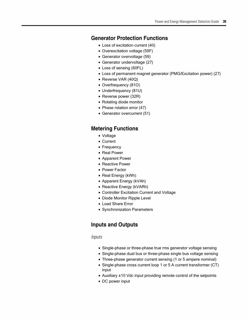
Generator Protection Functions• Loss of excitation current (40)• Overexcitation voltage (59F)• Generator overvoltage (59)• Generator undervoltage (27)• Loss of sensing (60FL)• Loss of permanent magnet generator (PMG/Excitation power) (27)• Reverse VAR (40Q)• Overfrequency (81O)• Underfrequency (81U)• Reverse power (32R)• Rotating diode monitor • Phase rotation error (47)• Generator overcurrent (51)
Metering Functions• Voltage• Current • Frequency• Real Power• Apparent Power• Reactive Power• Power Factor• Real Energy (kWh)• Apparent Energy (kVAh)• Reactive Energy (kVARh)• Controller Excitation Current and Voltage• Diode Monitor Ripple Level• Load Share Error• Synchronization Parameters
Inputs and Outputs
Inputs
• Single-phase or three-phase true rms generator voltage sensing • Single-phase dual bus or three-phase single bus voltage sensing• Three-phase generator current sensing (1 or 5 ampere nominal)• Single-phase cross current loop 1 or 5 A current transformer (CT)
input• Auxiliary ±10 Vdc input providing remote control of the setpoints• DC power input

40 Power and Energy Management Selection Guide
Outputs
• Pulse-width modulated output power stage rated at 15 amperes• Discrete redundancy relay output • Discrete fault output driver• Load sharing connection for use with Allen-Bradley 1402-LSM Line
Synchronization Module or compatible hardware
Communications Interfaces
The CGCM has three communication ports:
• Redundant ControlNet connector• RS-232 port for dedicated communication with a redundant CGCM• RS-232 port for factory configuration and test (not for customer use)
SpecificationsControl Power
Supply Burden
18 to 32V dc (24V dc Nominal) 30 W
Maximum AC Ripple
Dropout Voltage Profile
Operating Power Requirements
Source Phases Wiring Configuration Voltage Frequency VA (max)
PMG(1) 1-Phase PMG-A & PMG-C Min: 79 VrmsMax: 300 Vrms
Min: 50 HzMax: 240 Hz
3070
PMG 3-Phase Floating wye Min: 137 Vrms L-LMax: 300 Vrms L-L
Min: 50 HzMax: 240 Hz
3070
SE(2) 1-Phase PMG-A & PMG-C Min: 79 VrmsMax: 300 Vrms
Min: 50 HzMax: 240 Hz
3070
SE 3-Phase Floating wye Min: 137 Vrms L-LMax: 300 Vrms L-L
Min: 50 HzMax: 240 Hz
3070
SE 3-Phase Grounded wye
(Grounded neutral)
Min: 137 Vrms L-LMax: 300 Vrms L-L
Min: 50 HzMax: 240 Hz
3070
SE 3-Phase Floating delta Min: 137 Vrms L-LMax: 300 Vrms L-L
Min: 50 HzMax: 240 Hz
3070
SE 3-Phase Open delta, floating Min: 137 Vrms L-LMax: 300 Vrms L-L
Min: 50 HzMax: 240 Hz
3070
(1) PMG = Permanent Magnet Generator
(2) SE = Separately Excited
Power and Energy Management Selection Guide 41
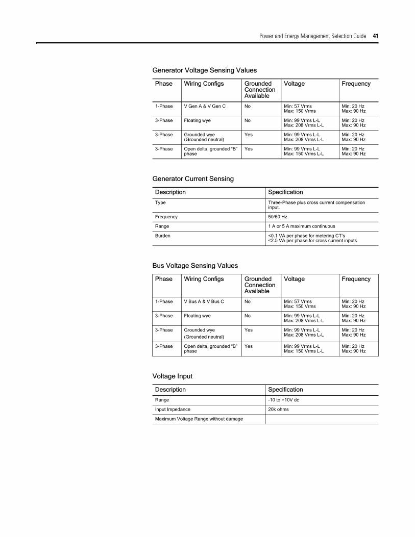
Generator Voltage Sensing Values
Phase Wiring Configs Grounded Connection Available
Voltage Frequency
1-Phase V Gen A & V Gen C No Min: 57 VrmsMax: 150 Vrms
Min: 20 HzMax: 90 Hz
3-Phase Floating wye No Min: 99 Vrms L-LMax: 208 Vrms L-L
Min: 20 HzMax: 90 Hz
3-Phase Grounded wye(Grounded neutral)
Yes Min: 99 Vrms L-LMax: 208 Vrms L-L
Min: 20 HzMax: 90 Hz
3-Phase Open delta, grounded “B” phase
Yes Min: 99 Vrms L-LMax: 150 Vrms L-L
Min: 20 HzMax: 90 Hz
Generator Current Sensing
Description Specification
Type Three-Phase plus cross current compensation input.
Frequency 50/60 Hz
Range 1 A or 5 A maximum continuous
Burden <0.1 VA per phase for metering CT’s<2.5 VA per phase for cross current inputs
Bus Voltage Sensing Values
Phase Wiring Configs Grounded Connection Available
Voltage Frequency
1-Phase V Bus A & V Bus C No Min: 57 VrmsMax: 150 Vrms
Min: 20 HzMax: 90 Hz
3-Phase Floating wye No Min: 99 Vrms L-LMax: 208 Vrms L-L
Min: 20 HzMax: 90 Hz
3-Phase Grounded wye
(Grounded neutral)
Yes Min: 99 Vrms L-LMax: 208 Vrms L-L
Min: 20 HzMax: 90 Hz
3-Phase Open delta, grounded “B” phase
Yes Min: 99 Vrms L-LMax: 150 Vrms L-L
Min: 20 HzMax: 90 Hz
Voltage Input
Description Specification
Range -10 to +10V dc
Input Impedance 20k ohms
Maximum Voltage Range without damage

42 Power and Energy Management Selection Guide
Dimensions
CNA
CNB
Manufactured by
aBR
BAT (-)
BAT (+)
DANGER
elrle Es ricc
4
5
HOSTFRN
COMMSFRN
LISTEDIND.CONT.EQ.
FORHAZ.LOC.
3PA7
COMBINATIONGENERATORCONTROLMOD
ULE
1407-CGCML UC
R
CAT
CNB
U.S.A.
RedundancyPort
AmbientOperatingRating:-20C̊to
70̊C
Foradditionalratingssee
User'sManual.
THISEQUIPMENTISSUITABLEFORUSEIN
CLASSIDIVISION
2,GROUPSA,B,C,ORD
A REV
e EQPTCL.2
US
c
B SER
TEMPERATUREINDEX**
T3
CLAS
SI,ZONE2
AEXnC
IICT3,Ex
nCIICT3
II3G
EE
xnLIICT3
DEMKO02ATEX0139272U
ORNON-HAZARDOUSLOCATIONSONLY
CNA
79-300VACL-L@50-240Hz
FAULT&REDUNDANCYOUTPUTS
0.5A@24VDC
VOLTAGEADJUSTINPUT
+/-10VDC
CURRENTSENSEINPUTS
0-5AAC
MADEIN
1.5ADC@24
VDC
EXCITERFIELDCURRENTOUTPUT
DCSUPPLYINPUT
GENERATORBREF.BUSIN
PUTS
57-208VACL-L@20-90Hz
PMGPOWERINPUT
0-15ADC
ID (+) 1A
ID (+) 5A
ID (-)
I3 (+) 1A
I3 (+) 5A
I3 (-)
I2 (+) 1A
I2 (+) 5A
I2 (-)
I1 (+) 1A
I1 (+) 5A
I1 (-)
TB5
TB6
TB3SHLD 2
SHLD 2
EXC (+)
EXC (-)
TB2CombinationGeneratorControl Module TB4
FLT
RD RLY
CH GND
TB7
ControlNetAddress
TB1
PMG A
PMG B
PMG C
SHLD 1
SHLD 1
V Bus A
V Bus BV Bus CV Bus N
V Gen A
V Gen BV Gen CV Gen N
VREF (+)VREF (-)SHLD 3SHLD 3A-COMEX-D (+)EX-D (-)LS (+)LS (-)
SHLD 4
FactoryTest Port
ControlNet 1.5Connections
9.75(247.7)
14.00(355.6)
1/4 - 20 GroundStud (2 Places)
0.281 (7.14) DIA Mounting Hole (6 Places) 8.25
(209.6)
6.26(159.0)
Notes:1. Heat Dissipation = 70 Watts Nominal 150 Watts (10 Second Forcing).2. Weight = 17 lbs. (7.7 kg).3. Dimensions are in inches (millimeters).
Ground Studs
HAZARDOUS VOLTAGE CAN CAUSE SHOCK, BURNS, OR DEATH.1) DISCONNECT AND LOCK OUT ALL POWER SOURCES AND,2) SHORT ALL CURRENT TRANSFORMER SECONDARIES BEFORE SERVICING.
MORE THAN ONE LIVE CIRCUIT. SEE DIAGRAM. ADVERTISSMENT: CET EQUIPEMENT RENFERME PLUSIEURS CIRCUITS SOUS TENSION, VOIR LE SCHEMA

Power and Energy Management Selection Guide 43
Power Management Software
Overview PEMS software is available for simple and complex systems. PEMS software helps you configure our Powermonitors and access energy data in real time.
Our software also enables you to capture, analyze, store, and share energy data across your entire enterprise through standard web browsers.This makes it easy for you to acquire and distribute the knowledge you need to optimize energy consumption and improve productivity while lowering energy costs.
RSPower32
Rockwell Automation’s RSPower32 is a stand-alone application as well as containing an ActiveX component for a user to configure and display information from Allen-Bradley power monitoring products. RSPower32 has simple screens for configuring and viewing data from power monitors. When combined with RSView32, RSPower32 adds these features directly to the RSView32 Project Manager interface as well as providing data for tags, alarming, data logging and trending.
Utilizing the exposed object model, RSView32 or other applications such as Visual Basic can use RSPower32’s data server to read and write data to power monitors and perform standard operations like setting the time, saving logs to disk, or capturing a waveform.
RSPowerPlus
RSPowerPlus is a Windows-based application that expands the RSPower32 functionality from configuration and real-time monitoring of Powermonitors to include simple billing and trending via the TOU (Time Of Use) function available in the Powermonitor 3000 products. Install RSPowerPlus as a stand-alone package or as an extension of RSView32 HMI software and begin working with your power monitoring equipment from your desktop. You can also upgrade your existing RSPower32 to include the billing and trending functionality available in RSPowerPlus.
RSEnergyMetrix
RSEnergyMetrix is sophisticated web-enabled energy management software that puts critical energy information at your desktop. The RSEnergyMetrix Software Suite combines data communication, client-server applications, and Microsoft’s advanced .Net web technology to provide you with a complete energy management solution. RSEnergyMetrix captures, analyzes, stores, and shares energy data across your entire enterprise. Using a simple web browser, your energy information can now be available on your company’s LAN or WAN, presenting you with the
Step 8 - Select: Software
• Select RSPower32, RSPowerPlus or RSEnergyMetrix,

44 Power and Energy Management Selection Guide
knowledge necessary to optimize your energy consumption. The net result- improved productivity and lower energy costs.
Selection Comparison
Product Selection
Application RSPower32 RSPowerPlus RSEnergy Metrix RSView32
Load Profiling
Cost Allocation
Power Quality Monitoring
Distribution System Monitoring
Demand Management (Optional) (Optional)
Emergency Load Shedding (Optional) (Optional)
Power System Control (Optional) (Optional)
Function RSPower32 RSPowerPlus RSEnergyMetrix
Configure A-B PMs
View, save and print PM data
Preconfigured consumption and billing reports
Imbedded real time and historical trend charts
Custom reports and charts
Complex rate tariffs
Client/Server application
RSPower32
Description Catalog Number
RSPower32 Works Without Communication Drivers(1)
(1) RSPower32 requires RSLinx OEM or higher.
9307-RSP32WENE
RSPower32 Runtime Without Communication Drivers(1) 9307-RSP32RENE
RSPower32 Works Bundled with Communication Drivers(2)
(2) Does not require RSLinx OEM or higher.
9307-RSP32LXWENE
RSPower32 Runtime Bundled with Communication Drivers(2) 9307-RSP32LXRENE
RSPowerPlus
Description Catalog Number
RSPowerPlus Works Without Communication Drivers(1) 9307-RSPPWENE
RSPowerPlus Runtime Without Communication Drivers(1) 9307-RSPPRENE
RSPowerPlus Works Bundled with Communication Drivers(2) 9307-RSPPLXWENE

Power and Energy Management Selection Guide 45
RSPowerPlus Runtime Bundled with Communication Drivers(2) 9307-RSPPLXRENE
RSPower32 Works to RSPowerPlus Works Upgrade 9307-RSPPWU1
RSPower32 Runtime to RSPowerPlus Runtime Upgrade 9307-RSPPRU1
(1) RSPowerPlus requires RSLinx OEM or higher.
(2) Does not require RSLinx OEM or higher.
RSEnergyMetrix
Description Catalog Number
RSEnergyMetrix Manager (0 to 8 meters) 9307-EM8MGRENE
RSEnergyMetrix Manager (9 to 64 meters) 9307-EM64MGRENE
RSEnergyMetrix Manager (65 to 10,000 meters) 9307-EM10KMGRENE
RSEnergyMetrix Real Time 9307-EMRTENE
RSEnergyMetrix 3rd Part OPC Client Connectivity (0 to 8 meters) 9307-EM83PXENE
RSEnergyMetrix 3rd Part OPC Client Connectivity (9 to 64 meters) 9307-EM643PXENE
RSEnergyMetrix 3rd Part OPC Client Connectivity (64 to 10,000) 9307-EM10K3PXENE
RSEnergyMetrix ReportsPlus 9307-EMRPTENE
RSEnergyMetrix ChartsPlus 9307-EMCHTENE
RSEnergyMetrix Manager (0 - 8 meters) Unlimited-User Runtime Client License with SQL Server 2000 Standard Edition Single-Processor Runtime Database license
9307-8MGDBPENE
RSEnergyMetrix Manager (9 - 64 meters) Unlimited-User Runtime Client License with SQL Server 2000 Standard Edition Single-Processor Runtime Database license
9307-64MGDBPENE
RSEnergyMetrix Manager (65 - 10K meters) Unlimited-User Runtime Client License with SQL Server 2000 Standard Edition Single-Processor Runtime Database license
9307-10KMGDBPENE
RSEnergyMetrix Manager (0 - 8 meters) Single-User Runtime Client License with SQL Server 2000 Standard Edition Single-Client Runtime Database license
9307-8MGDBCENE
RSEnergyMetrix Manager (9 - 64 meters) Single-User Runtime Client License with SQL Server 2000 Standard Edition Single-Client Runtime Database license
9307-64MGDBCENE
RSEnergyMetrix Manager (65 - 10K meters) Single-User Runtime Client License with SQL Server 2000 Standard Edition Single-Client Runtime Database license
9307-10KMGDBCENE
RSEnergyMetrix Single-User Runtime Client license 9307-EMDB1C
RSPowerPlus
Description Catalog Number

46 Power and Energy Management Selection Guide
Features RSPower32• Organize your Allen-Bradley Powermonitors into a graphical tree to
represent your specific configuration or view the Powermonitors in a sorted list.
• Upload and download your Powermonitor configuration parameters from your PC.
• Save the entire site configuration as well as the individual data from each Powermonitor.
• Simply point and click to generate configuration reports for on or more Powermonitors.
• continuous access to all power data from your PC.• Display your data in pop-up views of real-time data using
user-selectable engineering units for each parameter type.• Display historical data stored within the Powermonitor.• Integral Security to prevent unauthorized users from accessing the
Powermonitor commands while allowing everyone to utilize the data.• Flexible communications via RSLinx to communicate with
Powermonitors.• Contains an OPC/DDE server and utilizes ActiveX technology to
simultaneously provide Powermonitor data to many external software packages.
• Can be configured as an add-on to RSView32 to provide wizards and libraries to create a full-featured power management system.
• Pop-up windows are available to view, print, and save harmonic spectral data, waveforms, event logs, min/max logs, and snapshot logs.
• Displays the harmonic content of your electric signal on your PC screen in both spreadsheet and bar graph formats.
• Check power line condition before, during, or after a disturbance.

Power and Energy Management Selection Guide 47
RSPowerPlus
RSPowerPlus has all of the features of RSPower32 in addition to the following:
• Run pre-configured monthly or yearly electrical consumption reports for each individual Powermonitor utilizing the TOU function in the Powermonitor 3000 family of products.
• Run pre-configured monthly or yearly billing reports by manually entering consumption and demand rates utilizing the TOU function in the Powermonitor 3000 family of products.
• Display real-time trending for up to 5 parameters simultaneously.• Display historical trending for data directly from the trend log of each
meter.• User defined limits for monitoring of electrical parameters (i.e.
demand monitoring).
RSEnergyMetrix
Base Package:RSEnergyMetrix Manager
• Base package• Set up groups, domains, roles, users, devices, meters• Log data from Allen-Bradley devices• Basic reports and charts• Rate schedules and billing reports• 8, 64, or 10,000 meter licensing
Offered with or without Microsoft SQL Server 2000 Runtime license
Optional Packages:
RSEnergyMetrix ReportsPlus RSEnergyMetrix ChartsPlus RSEnergyMetrix 3PX RSEnergyMetrix RT
Optional package Optional package Optional package Optional package
Enhanced Reports Enhanced Charts Enables OPC Client in Manager Configure Allen-Bradley Powermonitors
Flexible formatting tools for customizing
Requires customer provided OPC server
View real-time data from Allen-Bradley Powermonitors

48 Power and Energy Management Selection Guide
Scalability -
RSEnergyMetrix interfaces to your existing systems through standard protocols and has the scalability to add additional components while maintaining your original investments.
• RSEnergyMetrix Manager: The core data logging, reporting, charting and billing package. Manager is a server-based, web-enabled application that runs on a Windows 2000 Server or Workstation. Microsoft Internet Explorer accesses and configures Manager. RSEnergyMetrix Manager is available with 8, 64 of 10,000 meters’ licenses.
• RSEnergyMetrix RT: The real-time communications, configuration and data display package of RSEnergyMetrix. RT is available with RSEnergyMetrix Manager or as a stand-alone package.
• RSEnergyMetrix 3PX: Provides connectivity to meters other than Allen-Bradley Powermonitors. Like Manager, the 3PX package is offered in 8, 64 and 10,000 meters’ licenses
• RSEnergyMetrix ReportsPlus: Creates custom reports beyond the standard reports included with Manager.
• RSEnergyMetrix ChartsPlus: Creates custom charting capabilities above the standard charts included with Manager
Connectivity -
Connect to metering points right from your desktop PC
• Connectivity through RSLinx: RS-232, RS-485, Ethernet, DeviceNet, RIO pass-thru, optical, and modem (RSLinx Lite is included with the manager package)
• Third part connectivity - OPC
Configuration -
RSEnergyMetrix provides easy and flexible configuration
• Configure Electricity, gas, water, and steam meters or any energy or production related inputs
• Configure Manual Meters as placeholders in the database for manual data entry
• Configure user defined data sources such as standard PLC-5 or SLC hardware types or Generic OPC
• Flexible configuration allows you to:
– Name your devices
– Name your groups
– Create sub-groups
– Put meters in multiple groupings for cost allocation
• Set and change meter configuration values remotely• Multi-level password protection and privileges

Power and Energy Management Selection Guide 49
Monitoring and Analysis:
RSEnergyMetrix is a powerful load profiling, cost allocation and billing analysis tool
• Log usage, cost and power quality data• View any parameter in real time• Create historical trend reports and charts• View historical trending of individual meters and groups and save
tabular data for further processing and analysis• Establish consumption baseline and user defined time of use periods• Create custom rate plans using the rate plan menu and line item
scripting• Assign rate plans to meters or groups of meters• Import and export rate schedules in XML format• Create and print daily or monthly cost and billing reports by:
– Meter
– Business group
– Department
– Site
• Create energy budgets and forecasts• Compare and contrast alternative utility rates; do “what-if” for other
rate structures• Print and store all reports and charts
Guidelines for Server Sizing
The following rules of thumb are offered as a starting point for determining server sizing for RSEnergyMetrix. Other factors affect the required size of a server. A higher number of tags being logged, a faster log rate, a larger number of users and a larger number of reports being run will require a more powerful server than the guidelines specify.
A low-end server has up to 8 meters and logs up to 40 meter tags at a minimum 15 minute log rate. A mid-range server has up to 64 meters and logs up to 320 meter tags at a minimum 15 minute log rate. A high-end server has more than 64 meters and logs more than 500 meter tags at a minimum 15 minute log rate.
Database Size Guidelines
RSEnergyMetrix writes 16 bytes of data to the database for each meter tag logged. Over time, the database can grow to become quite large. Some examples:
• A low-end server, logging 40 meter tags at 15 minute intervals, will grow the database at a rate of 2.56 KB per hour or 22 MB per year.
• A mid-level server, logging 320 meter tags at 15 minute intervals, will grow the database at a rate of 20.5 KB per hour, or 180 MB per year.

50 Power and Energy Management Selection Guide
12.pdf
Rigatel. +klink
.ua
• A high-end server, logging 1000 meter tags at 15 minute intervals, will grow the database at a rate of 240 KB per hour, or 2.1 GB per year.
Consider these guidelines when determining hard disk requirements for a server as well as database maintenance schedules.
Hardware Requirements
These are general guidelines. RSEnergyMetrix is capable of running on a variety of hardware platforms. The main scalability issue is related to processing of logged data (e.g. report generation, trending). CPU speed, number of CPUs, RAM, and RAID 5 for the database files are the main scalability factors (in that order).
A low end-server:
• Windows 2000 Server• SQL Server 2000 Standard• Single 500+ MHz Pentium III• 512 MB RAM• 10 GB hard disk
Mid-range server:
• Windows 2000 Server or Advanced Server• SQL Server 2000 Standard or Enterprise• 2 or 4 CPU 800+ MHz Pentium III or better• 1 GB RAM or higher• 30 GB hard disk (with separate disks for operating system and log
files and RAID 5 for main database files preferred)
High-end server
A high-end server specification is highly dependent upon the user’s requirements. Please contact Rockwell Automation for more information.
Rockwell_Power_Energy_Powermonitor_Select_en_08
Samaratel. +7 846 273 95 [email protected]
Yekaterinburgtel. +7 343 287 19 [email protected]
St. Petersburgtel. +7 812 327 [email protected]
Moscowtel. +7 495 641 [email protected]
Helsinkitel. +358 9 540 [email protected]
Vilnius МinskTallinn
Кievtel. +38 044 495 33 [email protected]
www.klinkmann.com
tel. +370 5 215 [email protected]
371 6738 [email protected]
tel. +375 17 200 [email protected]
tel. +372 668 [email protected]