Embed Size (px)
Citation preview

135 – Norwegian Oil and Gas Recommended guidelines for Classification and categorization of well control incidents and well integrity incidents Original version
PREFACE
This guideline is supported by Norwegian Oil and Gas Association's (Norwegian Oil and Gas) Drilling Managers Forum and by Norwegian Oil and Gas’ Operations Committee. Further it has been approved by Norwegian Oil and Gas’ general director. Responsible manager in Norwegian Oil and Gas is Manager drilling who can be contacted via +47 51 84 65 00 (switchboard). The guideline has been prepared with a broad participation from competent parties in the Norwegian petroleum industry, and is owned by the Norwegian petroleum industry, as represented by Norwegian Oil and Gas Association. Norwegian Oil and Gas is responsible for administration of this guideline. Norwegian Oil and Gas Association Vassbotnen 1, 4313 Sandnes P.O. Box 8065 4068 Stavanger, Norway Tel.: + 47 51 84 65 00 Web site: www.norskoljeoggass.no E-mail: [email protected]
Norwegian Oil and Gas Recommended Guidelines for Classification and categorization of well control incidents and well integrity incidents
No: 135 Established: 2012.05.30 Revision no: 04 Date revised: 2017.06.27 Page: 2
Norwegian Oil and Gas Recommended Guidelines for Classification and categorization of well control incidents and well integrity incidents
No: 135 Established: 2012.05.30 Revision no: 04 Date revised: 2017.06.27 Page: 3
CONTENT
PREFACE ................................................................................................................................. 2
CONTENT ............................................................................................................................... 3
1 INTRODUCTION.............................................................................................................. 4
1.1 Purpose ..................................................................................................................................... 4
1.2 Terminology ............................................................................................................................ 4
2 GUIDELINE WELL CONTROL INCIDENTS ........................................................... 6
2.1 Description of the matrix ................................................................................................... 6
2.1.1 Drilling and completion colour codes ........................................................................ 6
2.1.2 Well intervention – colour codes column on left hand side .............................. 7
2.1.3 Alert and notification to Authorities .......................................................................... 7
2.1.4 Guidance and examples................................................................................................... 7
3 ONE PAGE WELL CONTROL INCIDENT PRESENTATION ............................. 8
4 GUIDELINE WELL INTEGRITY INCIDENTS ........................................................ 8
4.1 Description of matrix ........................................................................................................... 8
4.1.1 Colour codes for Level and Consequence classification ..................................... 8
4.1.2 Principles for Classification of well integrity incidents ...................................... 9
4.1.3 Internal reporting .............................................................................................................. 9
5 ONE PAGE WELL INTEGRITY INCIDENT PRESENTATION .......................... 9
App A Flowchart for process of reporting and experience transfer of well control incidents .................................................................................................. 10
App B Categorisation and classification matrix for well control incidents 11
App C Examples of incidents ........................................................................................ 13
APP E Categorization and classification matrix for well integrity incidents ... …………………………………………………………………………………………………. 17
App F Examples of Well Integrity Incidents ........................................................... 18
App G Template for one page well integrity incident presentation .............. 19
6 HIGHLIGHTING CHANGES ....................................................................................... 20
Norwegian Oil and Gas Recommended Guidelines for Classification and categorization of well control incidents and well integrity incidents
No: 135 Established: 2012.05.30 Revision no: 04 Date revised: 2017.06.27 Page: 4
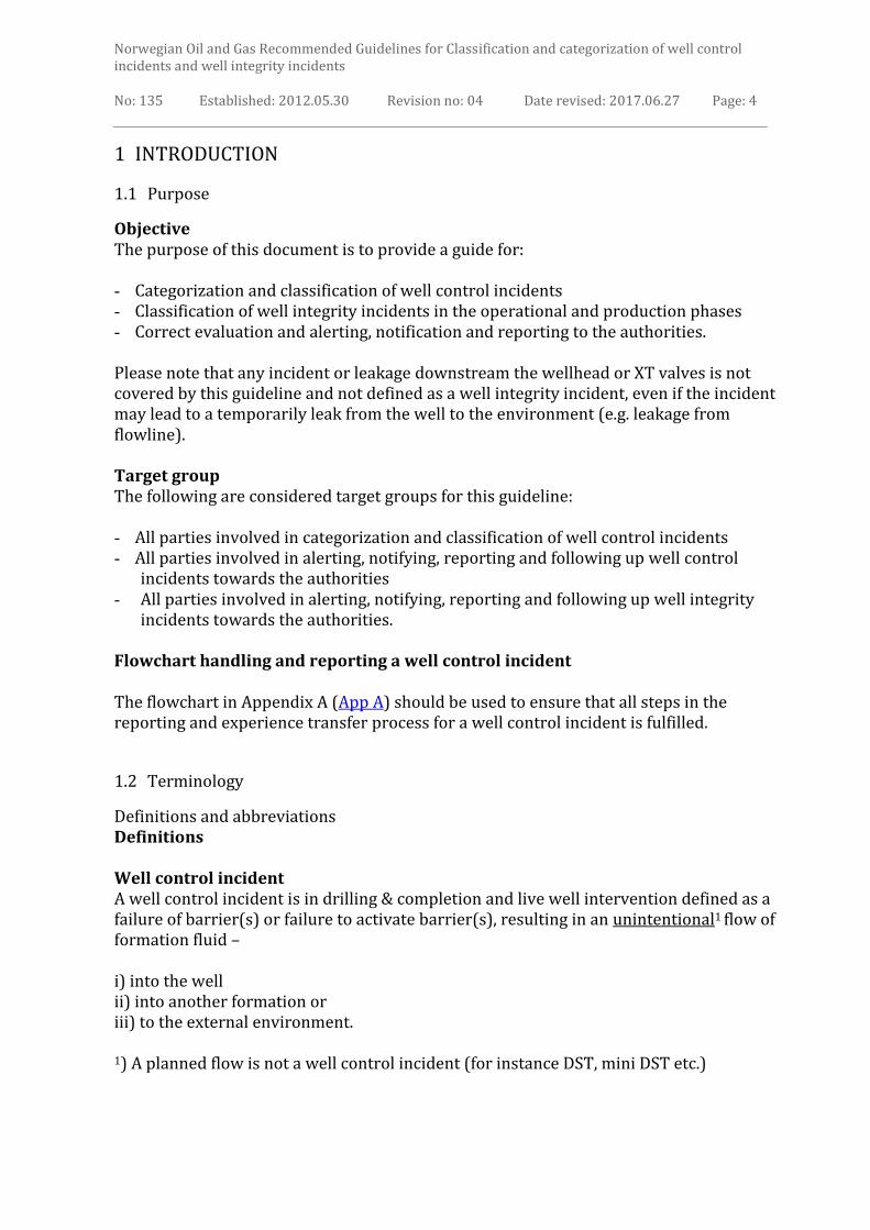
1 INTRODUCTION
1.1 Purpose
Objective The purpose of this document is to provide a guide for: - Categorization and classification of well control incidents - Classification of well integrity incidents in the operational and production phases - Correct evaluation and alerting, notification and reporting to the authorities. Please note that any incident or leakage downstream the wellhead or XT valves is not covered by this guideline and not defined as a well integrity incident, even if the incident may lead to a temporarily leak from the well to the environment (e.g. leakage from flowline). Target group The following are considered target groups for this guideline: - All parties involved in categorization and classification of well control incidents - All parties involved in alerting, notifying, reporting and following up well control
incidents towards the authorities - All parties involved in alerting, notifying, reporting and following up well integrity
incidents towards the authorities. Flowchart handling and reporting a well control incident The flowchart in Appendix A (App A) should be used to ensure that all steps in the reporting and experience transfer process for a well control incident is fulfilled.
1.2 Terminology
Definitions and abbreviations Definitions Well control incident A well control incident is in drilling & completion and live well intervention defined as a failure of barrier(s) or failure to activate barrier(s), resulting in an unintentional1 flow of formation fluid – i) into the well ii) into another formation or iii) to the external environment. 1) A planned flow is not a well control incident (for instance DST, mini DST etc.)

Norwegian Oil and Gas Recommended Guidelines for Classification and categorization of well control incidents and well integrity incidents
No: 135 Established: 2012.05.30 Revision no: 04 Date revised: 2017.06.27 Page: 5
Well integrity incident A well integrity incident is defined as a failure of barrier(s) or failure to activate barrier(s), resulting in an unintentional flow, leak or release of fluids to the environment or other formations.
Drilling and Completion operation Drilling, completion or work-over activity. Well Intervention operation Well intervention operation is well servicing operations conducted within a completed wellbore. Abbreviations BOP Blow Out Preventer CDRS Common Data Reporting System (NPD/PSA database) DMF Drilling Managers Forum DST Drill Stem Test DHSV Down Hole Safety Valve D&W Drilling & Well HC Hydrocarbons HMV Hydraulic Master Valve MMV Manual Master Valve NCS Norwegian Continental Shelf
Norwegian Oil and Gas Norwegian Oil and Gas Association PSA Petroleum Safety Authority RNNP Risk level Norwegian Petroleum industry TH Tubing Hanger TTAC Tubing to annulus communication WH Well Head XT Christmas Tree

Norwegian Oil and Gas Recommended Guidelines for Classification and categorization of well control incidents and well integrity incidents
No: 135 Established: 2012.05.30 Revision no: 04 Date revised: 2017.06.27 Page: 6
2 GUIDELINE WELL CONTROL INCIDENTS
The matrix in App B shall be used to classify the seriousness of a well control incident. The matrix defines the criticality of a loss of barrier(s). It does not include an evaluation of the potential consequences of a well control incident – this shall be assessed separately and according to the company’s internal incident evaluation process. In App C are listed examples of classifications of incidents according to App B. There is one matrix for drilling and completion operations and one matrix for well intervention operations.
2.1 Description of the matrix
2.1.1 Drilling and completion colour codes
The matrix’s left column is organized according to criticality into four color coded categories: - Red – Critical well control incidents - Yellow – Serious well control incidents - Green – Regular well control incidents - Grey – None classified incidents (not reportable to PSA). Red incidents; graded 1 – 4: Grade 1: Blowout. Grade 2: High HC influx rate Grade 3: High rate Shallow gas flow Grade 4: High rate Shallow water flow. Yellow incidents; graded 1 - 3: Grade 1: Medium HC influx, volume > kick tolerance that can be handled with kill procedures. Grade 2: Loss of fluid barrier requiring closure of BOP. Grade 3: Medium rate shallow gas flow to seabed or diverted on installation. Green incidents; graded 1 - 3: Grade 1: Low HC or water influx, volume < kick tolerance that can be handled with
well control procedures Grade 2: Low rate shallow gas with no gas on the installation. Grade 3: Low rate shallow water flow. Grey incidents; incidents such as non-continuous HC migration.
Norwegian Oil and Gas Recommended Guidelines for Classification and categorization of well control incidents and well integrity incidents
No: 135 Established: 2012.05.30 Revision no: 04 Date revised: 2017.06.27 Page: 7
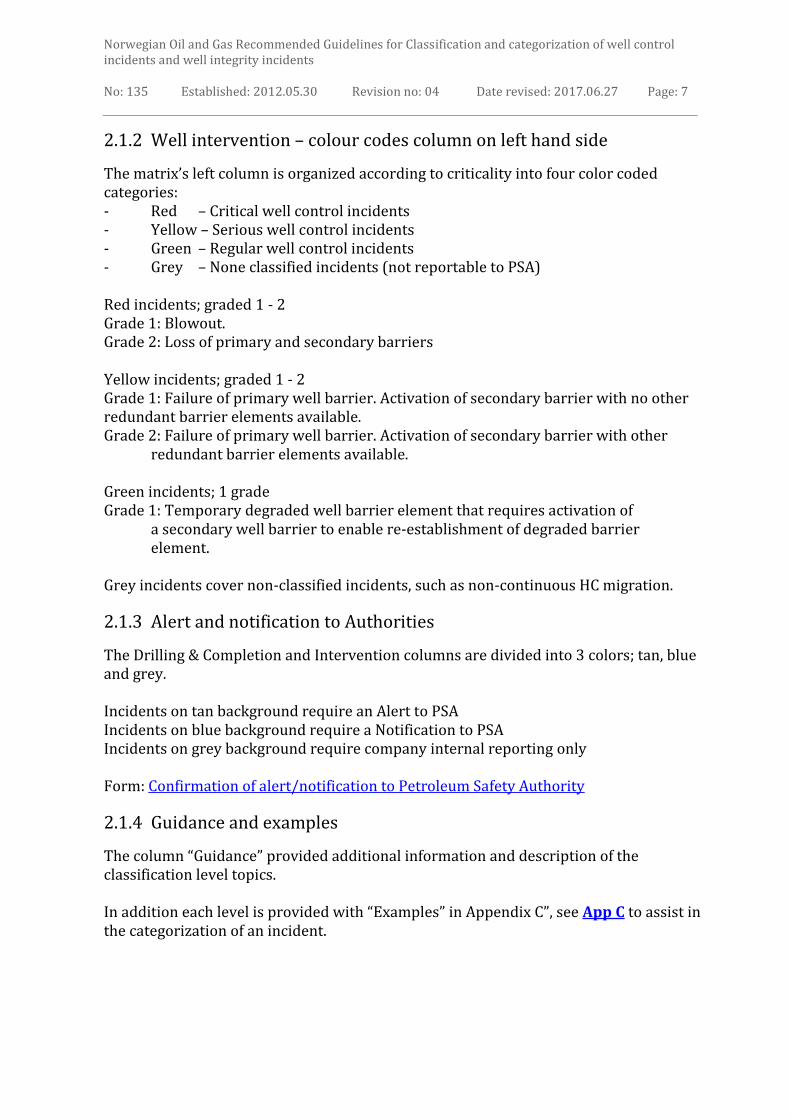
2.1.2 Well intervention – colour codes column on left hand side
The matrix’s left column is organized according to criticality into four color coded categories: - Red – Critical well control incidents - Yellow – Serious well control incidents - Green – Regular well control incidents - Grey – None classified incidents (not reportable to PSA) Red incidents; graded 1 - 2 Grade 1: Blowout. Grade 2: Loss of primary and secondary barriers Yellow incidents; graded 1 - 2 Grade 1: Failure of primary well barrier. Activation of secondary barrier with no other redundant barrier elements available. Grade 2: Failure of primary well barrier. Activation of secondary barrier with other redundant barrier elements available. Green incidents; 1 grade Grade 1: Temporary degraded well barrier element that requires activation of
a secondary well barrier to enable re-establishment of degraded barrier element.
Grey incidents cover non-classified incidents, such as non-continuous HC migration.
2.1.3 Alert and notification to Authorities
The Drilling & Completion and Intervention columns are divided into 3 colors; tan, blue and grey. Incidents on tan background require an Alert to PSA Incidents on blue background require a Notification to PSA Incidents on grey background require company internal reporting only Form: Confirmation of alert/notification to Petroleum Safety Authority
2.1.4 Guidance and examples
The column “Guidance” provided additional information and description of the classification level topics. In addition each level is provided with “Examples” in Appendix C”, see App C to assist in the categorization of an incident.

Norwegian Oil and Gas Recommended Guidelines for Classification and categorization of well control incidents and well integrity incidents
No: 135 Established: 2012.05.30 Revision no: 04 Date revised: 2017.06.27 Page: 8
3 ONE PAGE WELL CONTROL INCIDENT PRESENTATION
Appendix D, ( App D), is a “One page well control incident presentation” template. The intention is to have a standard format for presenting well control incidents for experience transfer within DMF.
4 GUIDELINE WELL INTEGRITY INCIDENTS
The matrix presented in Appendix E (App E) is a guide for classifying seriousness of a well integrity incident.
In Appendix F there is a list of examples of incident classifications. These are examples only (App F).
4.1 Description of matrix
4.1.1 Colour codes for Level and Consequence classification
The matrix is, in the left column, divided into four different colours based on degree of seriousness;
Red – Critical well integrity incidents with high risk for personnel, environment and facility. Orange – Serious well integrity incidents. Yellow – Medium well integrity incidents, three level, one grade of severity. Grey – Minor well integrity incidents not reportable to PSA.
The right-hand column of the matrix details the basics for grading within each classification level. Alert and Notification to authorities
Incidents on tan background require an Alert to PSA Incidents on blue background require a Notification to PSA Incidents on grey background require company internal reporting
Form: Confirmation of alert/notification to Petroleum Safety Authority

Norwegian Oil and Gas Recommended Guidelines for Classification and categorization of well control incidents and well integrity incidents
No: 135 Established: 2012.05.30 Revision no: 04 Date revised: 2017.06.27 Page: 9
4.1.2 Principles for Classification of well integrity incidents
Refer to appendix E. The matrix describes in the right-hand column two types of well integrity incidents: 1. Well barrier failure principles 2. HC release from well independent of well barrier failure The incident is defined by two digits: 1 – 4 for level of seriousness (left column with colours from red to grey) 1 – 3 for grade of severity (right hand column) Examples of reporting:
• Refer to appendix F: Examples of Well Integrity Incidents
4.1.3 Internal reporting
Each company to follow their requirements for internal reporting, investigation and experience transfer based on the consequence classification.
5 ONE PAGE WELL INTEGRITY INCIDENT PRESENTATION
Appendix G (App G) is a “one page well integrity incident presentation” template.
The intention is to have a standard format for presenting well integrity incidents for
experience transfer within WIF/DMF.

Norwegian Oil and Gas Recommended Guidelines for Classification and categorization of well control incidents and well integrity incidents
No: 135 Established: 2012.05.30 Revision no: 04 Date revised: 2017.06.27 Page: 10
App A Flowchart for process of reporting and experience transfer of well control incidents
Well control
incident
Notify PSA
according to
regulation and
company routine
Evaluate according to ”Guideline for
classification” if incident needs Alert
or Notification to PSA?
Register according
to internal
company
requirements
Categorise according
to ”Guideline for
classification”
Need
investigation?
Operators to clarifiy
with PSA incidents to
be included in RNNP
(annual process –
normally January)
Prepare company internal
report and ”One page Well
Control Incident Presentation”
(Experience transfer)
Y Perform investigation
N
Y
Issue ”One page well control
incident presentation” to DMF
for experience transfer
Company internal
process to evaluate
all actual and
potential
consequences.
Initiate and verify
kick report
registered in CDRS
FLOWCHART FOR HANDLING, REPORTING AND EXPERIENCE TRANSFER OF WELL CONTROL INCIDENTS
N
Evaluate if
”Guideline for
classification” needs
to be updated
Evaluate if case is
suitable for ”Sharing to
be Better” initiative

Norwegian Oil and Gas Recommended Guidelines for Classification and categorization of well control incidents and well integrity incidents
No: 135 Established: 2012.05.30 Revision no: 04 Date revised: 2017.06.27 Page: 11
App B Categorisation and classification matrix for well control incidents
Matrix for categorization and classification of well control incidents Drilling and Completion operations
Level 1- Red Critical well control incidents
1. Blowout 1. Blowout to environment or facility
including underground blow out.
Failure or malfunction of primary and
secondary barriers.
2. High HC influx
volume/rate 2. Failure of primary well barrier.
Successful a ctivation of the secondary
well barrier. Critical kill operations
with high risk of blowout.
3. High rate shallow gas
flow 3. Shallow gas incident with unsuccessful
kill operation. Gas flowing to seabed or
installation (diverter), until all gas is
released.
4. High rate shallow water
flow 4. Shallow water flow influencing stability
of an installation (jack-up, fixed
installation or template) Level 2 – Yellow Serious well control incidents
1. Medium HC influx volume/rate
1. Influx volume above design criteria for
kick margin, but possible to regain
barrier with standard kill procedure.
2. Total Fluid barrier lost 2. Loss situation without being able to maintain the hydrostatic pressure in the
well.
3. Medium rate shallow gas
flow 3. S hallow gas incident with kill
operations or gas handled on installation by diverter.
Level 3 – Green Regular well control incidents
1. Low HC or water influx
volume/rate 1. Influx volume below design
criteria for kick margin, and
successfully regained barrier with
standard kill procedure without
degrading well integrity.
2. Low rate shallow gas
flow 2. Shallow gas incident with kill
operations. No gas handled on
installation (riser-less operation)
3. Low rate shallow water
flow 3. Shallow water flow incident.
Level 4 - Non-Classified (NC)
1. Non-continuous
gas/water migration in
well - with all barriers
in place
1. Release of a barrier element with
contained volume of gas/water trapped
below or behind casing.
Tan = Alert to PSA according to management regulation Blue = Notification to PSA according to management regulation Grey = Alert or Notification to PSA not required

Norwegian Oil and Gas Recommended Guidelines for Classification and categorization of well control incidents and well integrity incidents
No: 135 Established: 2012.05.30 Revision no: 04 Date revised: 2017.06.27 Page: 12
Matrix for categorization and classification of well control incidents Well intervention operations
Degree of seriousness
Well intervention Guidance
Level 1- Red Critical well control incidents
1. Blowout
1. Blowout to environment or facility.
Failure of primary and secondary barriers
that can be handled by relief well drilling,
capping or handled on the installation
2. Failure of primary and
secondary barriers
2. Well control equipment damaged from
external loads or non-shearable item stuck
across BOP and safety head. Well flowing
to surroundings. Well killed or well
capped on location.
Level 2 – Yellow Serious well control incidents
1. Failure of primary well
barrier. Activation of
secondary well barrier –
no other redundant
barrier elements
available.
1. Well secured by closing one single valve
(safety head or XT valve). String blocking
other valves preventing redundant barrier
element.
2. Failure of primary well
barrier. Activation of
secondary well barrier –
other redundant barrier
elements available
2. Well secured by closing one single valve
(safety head or XT valve). Additional
valve(s) available to act as redundant
barrier element.
Level 3 – Green Regular well control incidents
1. Temporary reduction of
well barrier element
function
1. Failure of one well barrier element.
Activation of redundant well barrier
elements and reestablishment of well
barrier element within primary barrier.
Secondary barrier intact.
Level 4 – Non- Classified (NC)
1. Very small leak, no
activation of BOP
necessary.
1. Very small leak, able to pull out of hole
and close normal lubricator valves to
repair leak. Two barriers intact.
Tan = Alert to PSA according to management regulation Blue = Notification to PSA according to management regulation Grey = Alert or Notification to PSA not required Form: Confirmation of alert/notification to Petroleum Safety Authority

Norwegian Oil and Gas Recommended Guidelines for Classification and categorization of well control incidents and well integrity incidents
No: 135 Established: 2012.05.30 Revision no: 04 Date revised: 2017.06.27 Page: 13
App C Examples of incidents
No. 1. Blowout
D1.1 - 01 Blowout where the installation is evacuated and blowout handled from
remote location or another vessel (relief well, capping, etc.) D1.1 - 02 Underground blowout breaching to seabed. D1.1 - 03 Blowout breaches seabed but well killed from installation
2. High HC influx rate
D1.2 - 01 High influx volume (significantly above design criteria on kick margin) and
shear ram activated, i.e. in ultimate stage.
D1.2 - 02 Shut in pressure exceeding casing burst pressure or well control
equipment working pressure whichever is less.
D1.2 - 03 Loss of surface well control components leading to closing of shear seal
ram as only option.
D1.2 - 04 Shear seal ram closed due to internal blowout inside drill pipe (failure to
close IBOP/install FOSV)
D1.2 - 05 Riser evacuated to surface, loss of primary well barrier. BOP
activated and influx contained by secondary barrier, well killed from
installation.
3. High rate Shallow gas flow D1.3 - 01 Fixed installation or jack-up where gas blows to installation. D1.3 - 02 Floater where gas through sea is coming up to the installation. D1.3 - 03 Gas in such magnitude that instability of rig is experienced
D1.3 - 04 Jack up where gas breaches out on seabed threatening stability of
installation
D1.3 - 05 Long term diverting of gas with high potential for failure of diverting
system.
D1.3 - 06 Large OD top hole section riser less with gas flowing and unable to kill.
4. High rate shallow water flow
D1.4 - 01 Shallow water flow incident under a jack up or a fixed installation - no
threat to installation/template
1. Medium HC influx rate
D2.1 - 01 Medium/high influx volume (above design criteria on kick margin)
but kick circulated out using conventional kill method.
Note: Also valid for medium/high influx volume in sections
designed with infinite kick margin. D2.1 - 02 Underground blowout not breaching to seabed
2. Total Fluid barrier lost
D2.2 - 01 Sagging of mud resulting underbalanced situation -
(influx volume > kick margin) Handled using conventional kill methods.
D2.2 - 02 Loss situation without being able to maintain the hydrostatic pressure in
the well and closure of BOP with pressure underneath.
3. Medium rate Shallow gas flow
D2.3 - 01 Large OD top hole section riser less with gas flowing and able to kill
D2.3 - 02 Shallow gas diverted on installation.
1. Low HC or water influx rate
D3.1 - 01 Small HC kick volume (below design criteria on kick margin)
handled using conventional kill methods. D3.1 - 02 Water kick handled using conventional kill methods.
D3.1 - 03 Sagging of mud resulting underbalanced situation -
(influx volume < kick margin) Handled using conventional kill methods.
2. Low rate shallow gas
D3.2 - 01 Shallow gas incident with kill operations. No gas handled on installation
(riser-less operation).
3. Low rate Shallow water flow D3.3 - 01 Shallow water flow incident with no risk for stability of installation. D3.3 - 02 Shallow water flow left flowing. Respud new location.
Non-classified incidents
D4.1 - 01 Circulation of mud with high drilled gas content with closed BOP as
precautionary measure, but without applying additional backpressure.
D4.1 - 02 Circulate and increase mud weight due to increasing gas trend without
closing BOP. D4.1 - 03 Shallow gas bubbles from top hole section. D4.1 - 04 Released gas after cutting or perforation of casing string - no continuous flow
of gas.
Norwegian Oil and Gas Recommended Guidelines for Classification and categorization of well control incidents and well integrity incidents
No: 135 Established: 2012.05.30 Revision no: 04 Date revised: 2017.06.27 Page: 14
D4.1 - 05 Released gas after releasing downhole plugs/packers without having an
underbalanced situation in the well. D4.1 - 06 Lost mud returning into wellbore (ballooning). D4.1 - 07 Release of Nitrogen after a foam cement operation. D4.1 - 08 Release gas during pulling of cores
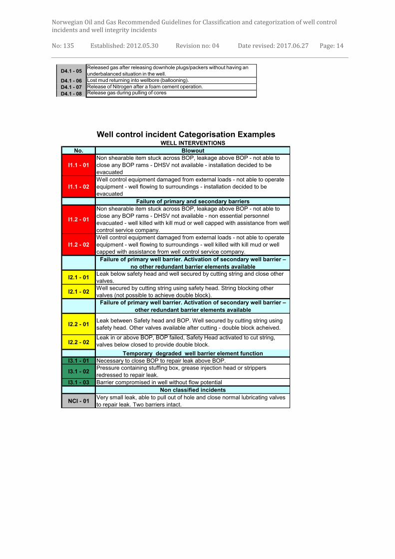
Well control incident Categorisation Examples WELL INTERVENTIONS
No. Blowout
I1.1 - 01
Non shearable item stuck across BOP, leakage above BOP - not able to
close any BOP rams - DHSV not available - installation decided to be
evacuated
I1.1 - 02
Well control equipment damaged from external loads - not able to operate
equipment - well flowing to surroundings - installation decided to be
evacuated
Failure of primary and secondary barriers
I1.2 - 01
Non shearable item stuck across BOP, leakage above BOP - not able to
close any BOP rams - DHSV not available - non essential personnel
evacuated - well killed with kill mud or well capped with assistance from well
control service company.
I1.2 - 02
Well control equipment damaged from external loads - not able to operate
equipment - well flowing to surroundings - well killed with kill mud or well
capped with assistance from well control service company.
Failure of primary well barrier. Activation of secondary well barrier –
no other redundant barrier elements available
I2.1 - 01Leak below safety head and well secured by cutting string and close other
valves.
I2.1 - 02Well secured by cutting string using safety head. String blocking other
valves (not possible to achieve double block).
Failure of primary well barrier. Activation of secondary well barrier –
other redundant barrier elements available
I2.2 - 01Leak between Safety head and BOP. Well secured by cutting string using
safety head. Other valves available after cutting - double block acheived.
I2.2 - 02Leak in or above BOP, BOP failed, Safety Head activated to cut string,
valves below closed to provide double block.
Temporary degraded well barrier element function
I3.1 - 01 Necessary to close BOP to repair leak above BOP.
I3.1 - 02Pressure containing stuffing box, grease injection head or strippers
redressed to repair leak.
I3.1 - 03 Barrier compromised in well without flow potential
Non classified incidents
NCI - 01Very small leak, able to pull out of hole and close normal lubricating valves
to repair leak. Two barriers intact.

Norwegian Oil and Gas Recommended Guidelines for Classification and categorization of well control incidents and well integrity incidents
No: 135 Established: 2012.05.30 Revision no: 04 Date revised: 2017.06.27 Page: 15
App D Template for one page well control incident presentation
See example below*

Norwegian Oil and Gas Recommended Guidelines for Classification and categorization of well control incidents and well integrity incidents
No: 135 Established: 2012.05.30 Revision no: 04 Date revised: 2017.06.27 Page: 16
Example of Well control incident category: *Typical examples: Medium risk HC influx - Drilling & Completion - (Yellow): Influx volume (above design criteria for kick margin) but possible to regain barrier with standard kill procedure – To be reported as D2.1 - 01 Temporary reduction of well barrier function – Well Intervention – (Green): Necessary to close BOP to repair leak above BOP – To be reported as I3.1 - 01

Norwegian Oil and Gas Recommended Guidelines for Classification and categorization of well control incidents and well integrity incidents
No: 135 Established: 2012.05.30 Revision no: 04 Date revised: 2017.06.27 Page: 17
APP E Categorization and classification matrix for well integrity incidents
Matrix for categorization and classification of well integrity incidents For wells in operation/production
Well Integrity Incident is defined as:
An incident that unintentionally changes or affects the status of the well barrier envelopes
GUIDELINE FOR CLASSIFICATION OF WELL INTEGRITY INCIDENTS
SERIOUSNESS LEVEL Type of Well Integrity incidence Guidance
LEVEL 1 – red: Critical well integrity incidents
with high risk for personnel, environment
and facility
BLOWOUT OR MAJOR HC RELEASE
Blowout to environment or facility. Failure of primary and secondary barriers that needs to be handled by relief well drilling, capping or handled on the installation.
LEVEL 2 – orange: Serious well integrity
incidents
HC RELEASE Failure of one barrier with release threatening parts of facility/plant or environment. Well secured by activating the intact barrier.
LEVEL 3 – yellow: Medium well integrity
incidents
1. CROSSFLOW Failure of one barrier resulting in uncontrolled cross flow between formations. No potential for breaching to surface or pollution.
2. LEAK Leak to environment through degraded barrier.
3. DUAL BARRIER FAILURE Two barrier failed. On site containment with no release to environment.
LEVEL 4 – Minor well integrity incidents:
1. SINGLE BARRIER FAILURE Leak through a barrier element. Pressure still contained by intact barrier.
2. MINOR LEAK Small HC release to environment not due to failure of well barrier.
Tan = Alert to PSA according to management regulation §29
Blue = Notification to PSA according to management regulation §29
Grey = Alert or Notification to PSA not required
Form: Confirmation of alert/notification to Petroleum Safety Authority

Norwegian Oil and Gas Recommended Guidelines for Classification and categorization of well control incidents and well integrity incidents
No: 135 Established: 2012.05.30 Revision no: 04 Date revised: 2017.06.27 Page: 18
App F Examples of Well Integrity Incidents
No. BLOWOUT OR MAJOR HC RELEASE
LEVEL 1
1 Loss of all well barriers, uncontrolled outflow
2
Casing leak below production packer into formation above reservoir. Packer set in uncemented casing. Release to environment.
3
Tubing and production casing leak resulting in leakage to an annulus not qualified as a barrier. Release to environment.
4 Loss of gas lift gas containment resulting in high amount of HC gas threatening the whole facility.
HC RELEASE
LEVEL 2 1 Release of gas lift gas with functioning ASV.
2 Flowline rupture and failure of XT valves resulting in large amount of HC release until DHSV closes.
1. CROSSFLOW
LEVEL 3
1
Casing leak below production packer into formation above caprock. Packer set in uncemented casing. No potential for breaching to surface.
2 Leak through cement into formation above cap rock. No potential for breaching to surface.
3 Leak of gas lift gas through production casing into formation. No potential for breaching to surface.
2. LEAK
1 Failure of DHSV and MMV stem packing resulting in HC release to environment
2 Gas lift leak into WH void and external leak through exit block.
3
Accumulated HC in B-annulus released through WH. If large amount of HC released evaluate to raise to Level 2 or 1
4 Tubing to annulus communication (TTAC) below DHSV and small leakage through XT valves to sea.
5 Leak in TH neck seal and XT/WH connection (ring gasket).
6 Leak in control line with small release to installation.
3. DUAL BARRIER FAILURE
1 DHSV, HMV & PMV failed but HC contained by valves down stream
2
Casing leak below production packer into formation above reservoir. Packer set in uncemented casing. Resulting in HC in an annulus not qualified as barrier.
3 Tubing and production casing leak resulting in leakage to an annulus not qualified as a barrier.

Norwegian Oil and Gas Recommended Guidelines for Classification and categorization of well control incidents and well integrity incidents
No: 135 Established: 2012.05.30 Revision no: 04 Date revised: 2017.06.27 Page: 19
1. SINGLE BARRIER FAILURE
LEVEL 4
1 Failure of DHSV other barrier elements intact.
2 Failure of HMV other barrier elements intact.
3 Tubing to annulus communication (TTAC)
4 Unacceptable TH neck seal leakage.
2. MINOR LEAK
1 Miss-operation of valves
App G Template for one page well integrity incident presentation

Norwegian Oil and Gas Recommended Guidelines for Classification and categorization of well control incidents and well integrity incidents
No: 135 Established: 2012.05.30 Revision no: 04 Date revised: 2017.06.27 Page: 20
6 HIGHLIGHTING CHANGES
Changes made: Appendix B – Categorisation and classification matrix for well control incidents Appendix C – Examples of incidents


![Check list [ DMF ]](https://img.dokumen.tips/doc/110x75/551e4149497959e4398b47bf/check-list-dmf-.jpg)