Embed Size (px)
Citation preview

GROSS LOAD CAPACITY WHEN USED AS A WEIGHT CARRYING HITCH: LBS. TRAILER WEIGHT & LBS. TONGUE WEIGHT. GROSS LOAD CAPACITY WHEN USED AS A WEIGHT DISTRIBUTION HITCH: LBS. TRAILER WEIGHT & LBS. TONGUE WEIGHT
***DO NOT EXCEED VEHICLE MANUFACTURER'S RECOMMENDED TOWING CAPACITY.***
HAVING INSTALLATION QUESTIONS? CALL TECHNICAL SUPPORT AT 1-800-798-0813
PERIODICALLY CHECK THIS RECEIVER HITCH TO ENSURE THAT ALL FASTENERS
ARE TIGHT AND THAT ALL STRUCTURAL COMPONENTS ARE SOUND.
Curt Manufacturing LLC., warrants this product to be free of defects in material and/or workmanship at the time of retail purchase by the original purchaser. If the product is found to be defective,Curt Manufacturing LLC., may repair or replace the product, at their option, when the product is returned, prepaid, with proof of purchase. Alteration to, misuse of, or improper installation ofthis product voids the warranty. Curt Manufacturing LLC.'s liability is limited to repair or replacement of products found to be defective, and specifically excludes liability for incidental orconsequential loss or damage.
3,500 3504,000 400
BMW X3
10/5/2012
13107
180
32
90
HITCH WEIGHT: LBS.
INSTALL TIME
PROFESSIONAL: MINUTES
NOVICE (DIY): MINUTES
INSTALL NOTES:
PAGE 1 OF 2
Parts List
DESCRIPTIONPART NUMBERQTYITEM
NYLON RIVET (AUVECO #20754)M6 RIVET141
TRIM
UNDERBODY PANEL TRIM DIAGRAM
518 in
734 in
UNDERBODY PANEL CENTER LINE
1
BUMPER BEAM ASSEMBLY
VEHICLE TRUNK PAN
TOOLS REQUIRED
PLASTIC RIVET GUN8, 10, 18 mm SOCKETS
RATCHETFLAT HEAD SCREWDRIVER
TORQUE WRENCH
TAPE MEASUREROTARY CUTTING TOOL
SMALL PUNCH
EXISTING M12 HARDWARE
- REMOVE BUMPER- TRIM UNDERBODY PANEL- NO DRILLING REQUIRED
GROSS LOAD CAPACITY WHEN USED AS A WEIGHT CARRYING HITCH: LBS. TRAILER WEIGHT & LBS. TONGUE WEIGHT. GROSS LOAD CAPACITY WHEN USED AS A WEIGHT DISTRIBUTION HITCH: LBS. TRAILER WEIGHT & LBS. TONGUE WEIGHT
***DO NOT EXCEED VEHICLE MANUFACTURER'S RECOMMENDED TOWING CAPACITY.***
HAVING INSTALLATION QUESTIONS? CALL TECHNICAL SUPPORT AT 1-800-798-0813
INSTALLATION STEPS
PERIODICALLY CHECK THIS RECEIVER HITCH TO ENSURE THAT ALL FASTENERS
ARE TIGHT AND THAT ALL STRUCTURAL COMPONENTS ARE SOUND.
Curt Manufacturing LLC., warrants this product to be free of defects in material and/or workmanship at the time of retail purchase by the original purchaser. If the product is found to be defective,Curt Manufacturing LLC., may repair or replace the product, at their option, when the product is returned, prepaid, with proof of purchase. Alteration to, misuse of, or improper installation ofthis product voids the warranty. Curt Manufacturing LLC.'s liability is limited to repair or replacement of products found to be defective, and specifically excludes liability for incidental orconsequential loss or damage.
3,500 3504,000 400
BMW X3
13107
PAGE 2 OF 2
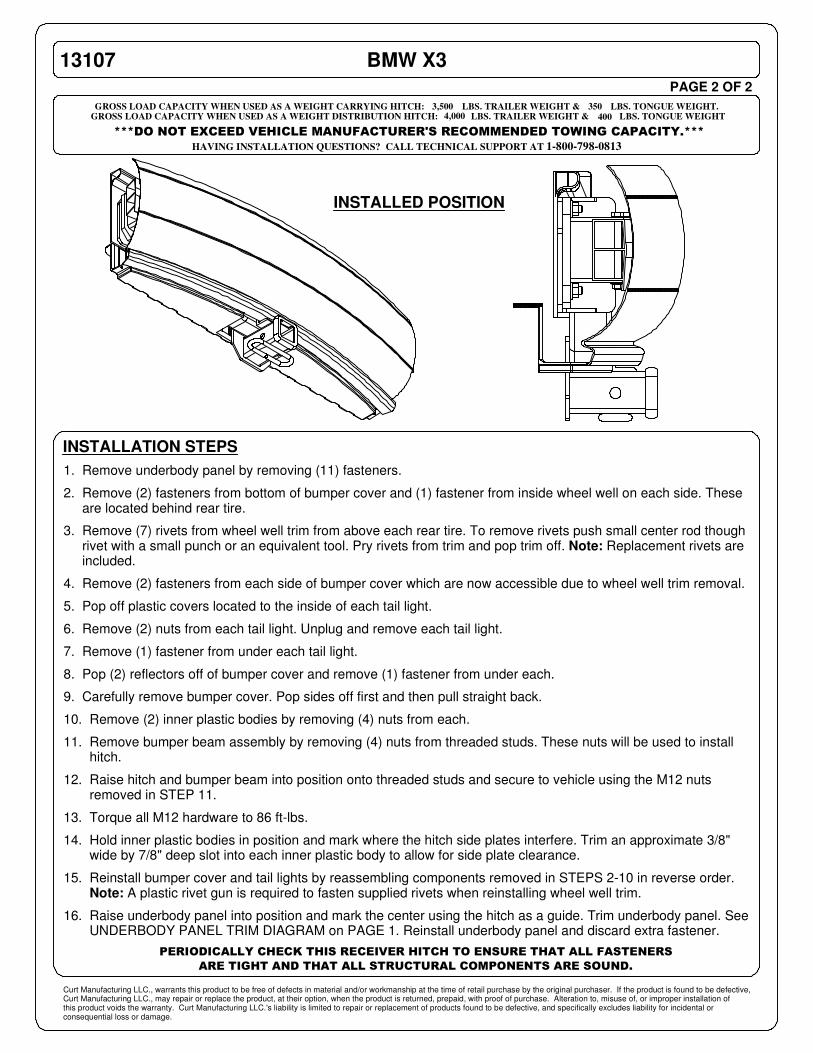
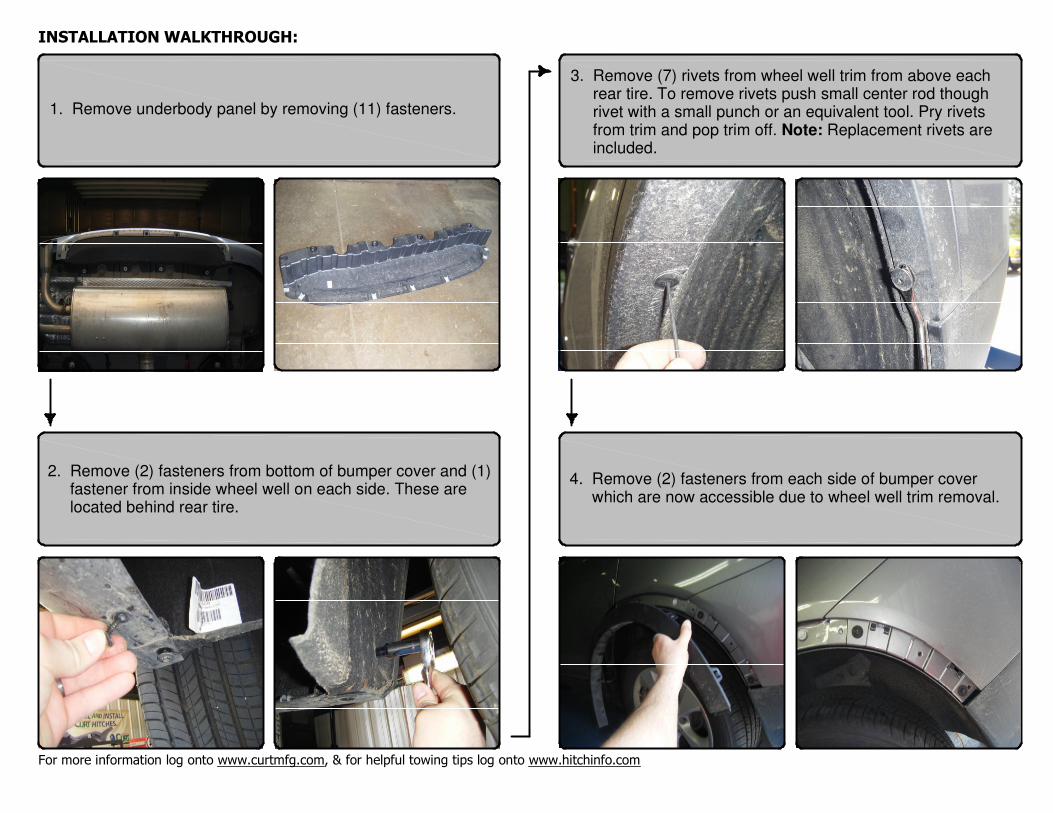
1. Remove underbody panel by removing (11) fasteners.
2. Remove (2) fasteners from bottom of bumper cover and (1) fastener from inside wheel well on each side. These are located behind rear tire.
3. Remove (7) rivets from wheel well trim from above each rear tire. To remove rivets push small center rod though rivet with a small punch or an equivalent tool. Pry rivets from trim and pop trim off. Note: Replacement rivets are included.
4. Remove (2) fasteners from each side of bumper cover which are now accessible due to wheel well trim removal.
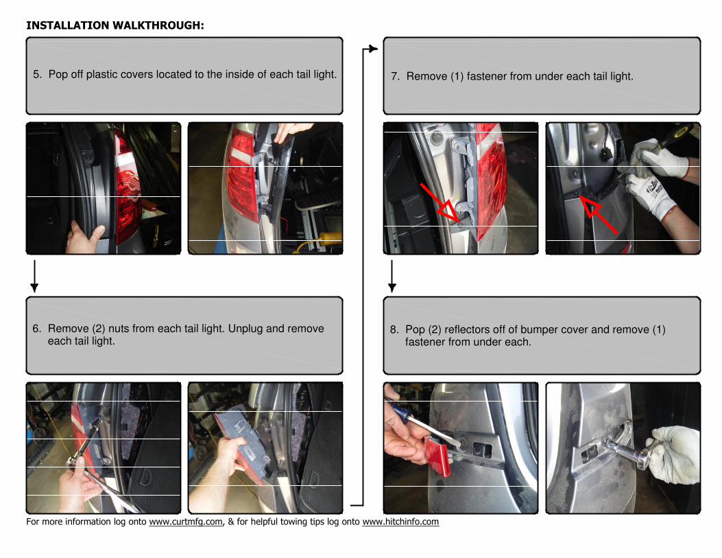
5. Pop off plastic covers located to the inside of each tail light.
6. Remove (2) nuts from each tail light. Unplug and remove each tail light.
7. Remove (1) fastener from under each tail light.
8. Pop (2) reflectors off of bumper cover and remove (1) fastener from under each.
9. Carefully remove bumper cover. Pop sides off first and then pull straight back.
10. Remove (2) inner plastic bodies by removing (4) nuts from each.
11. Remove bumper beam assembly by removing (4) nuts from threaded studs. These nuts will be used to install hitch.
12. Raise hitch and bumper beam into position onto threaded studs and secure to vehicle using the M12 nuts removed in STEP 11.
13. Torque all M12 hardware to 86 ft-lbs.
14. Hold inner plastic bodies in position and mark where the hitch side plates interfere. Trim an approximate 3/8" wide by 7/8" deep slot into each inner plastic body to allow for side plate clearance.
15. Reinstall bumper cover and tail lights by reassembling components removed in STEPS 2-10 in reverse order. Note: A plastic rivet gun is required to fasten supplied rivets when reinstalling wheel well trim.
16. Raise underbody panel into position and mark the center using the hitch as a guide. Trim underbody panel. See UNDERBODY PANEL TRIM DIAGRAM on PAGE 1. Reinstall underbody panel and discard extra fastener.
INSTALLED POSITION

PERIODICALLY CHECK THIS RECEIVER HITCH TO ENSURE ALL FASTENERS ARE TIGHT AND ALL STRUCTURAL COMPONENTS ARE SOUNDCURT Manufacturing LLC. warrants this product to be free of defects in material and/or workmanship at the time of retail purchase by the original purchaser. If the product is found to be defective, Curt Manufacturing LLC. may repair or replacethe product at their option, when the product is returned, prepaid, with proof of purchase. Alteration to, misuse of, or improper installation of this product voids the warranty. Curt Manufacturing LLC.'s liability is limited to repair or replacementof products found to be defective, and specifically excludes liability for incidental or consequential loss or damage.
For more information log onto www.curtmfg.com, & for helpful towing tips log onto www.hitchinfo.com
MAKE: STYLE:
MIN.90
WARNING: NEVER EXCEED YOUR VEHICLE MANUFACTURER'S RECOMMENDED TOWING CAPACITY
WEIGHT CARRYING:
INSTALLATION TIPS: INSTALLATION TIME:
INSTALLATION REQUIRES:
VEHICLE PHOTO:
HITCH ILLUSTRATION:
REPRESENTATIVE PHOTO
MAKE SURE YOUR HITCH MATCHES
LEVEL OF DIFFICULTY: CHALLENGING
EASY MODERATE CHALLENGING
THE INSTALL TIME LISTED IS FOR PROFESSIONAL
INSTALLERS. IF YOU ARE HESITANT TO UNDERTAKE
THIS TASK ON YOUR OWN, CONTACT AN AUTHORIZED
CURT INSTALLER FOR ADDITIONAL ASSISTANCE.
1. BEFORE YOU BEGIN INSTALLATION, READ ALL
INSTRUCTIONS THOROUGHLY.
2. TO EASE INSTALLATION, 2 PEOPLE MAY BE
REQUIRED.
3. USING PROPER TOOLS WILL GREATLY IMPROVE
THE QUALITY OF THE INSTALL AND REDUCE THE
TIME REQUIRED.
4. NEED HELP OR HAVE SOME QUESTIONS?
CALL TECHNICAL SUPPORT AT 800.798.0813
Safety glasses should be worn at all times whileinstalling this product.
YEARS: 2011-PRESENT BMW MODEL: X3 SUV
3,500
350
TRAILER WEIGHT:
TONGUE WEIGHT:
13107 INSTALLATION INSTRUCTIONS
LBS.
LBS.
10/5/2012
WEIGHT DISTRIBUTION: TRAILER WEIGHT:
TONGUE WEIGHT:
4,000
400
LBS.
LBS.
PART REMOVAL
REMOVE BUMPER
TRIM UNDERBODY PANEL
NO DRILLING REQUIRED
PLASTIC
RIVET GUN SOCKET
8mm10mm18mm
RATCHET
SCREWDRIVER
TORQUEWRENCH
TAPEMEASURE
ROTARY TOOLSAFETYGLASSESSMALL PUNCH
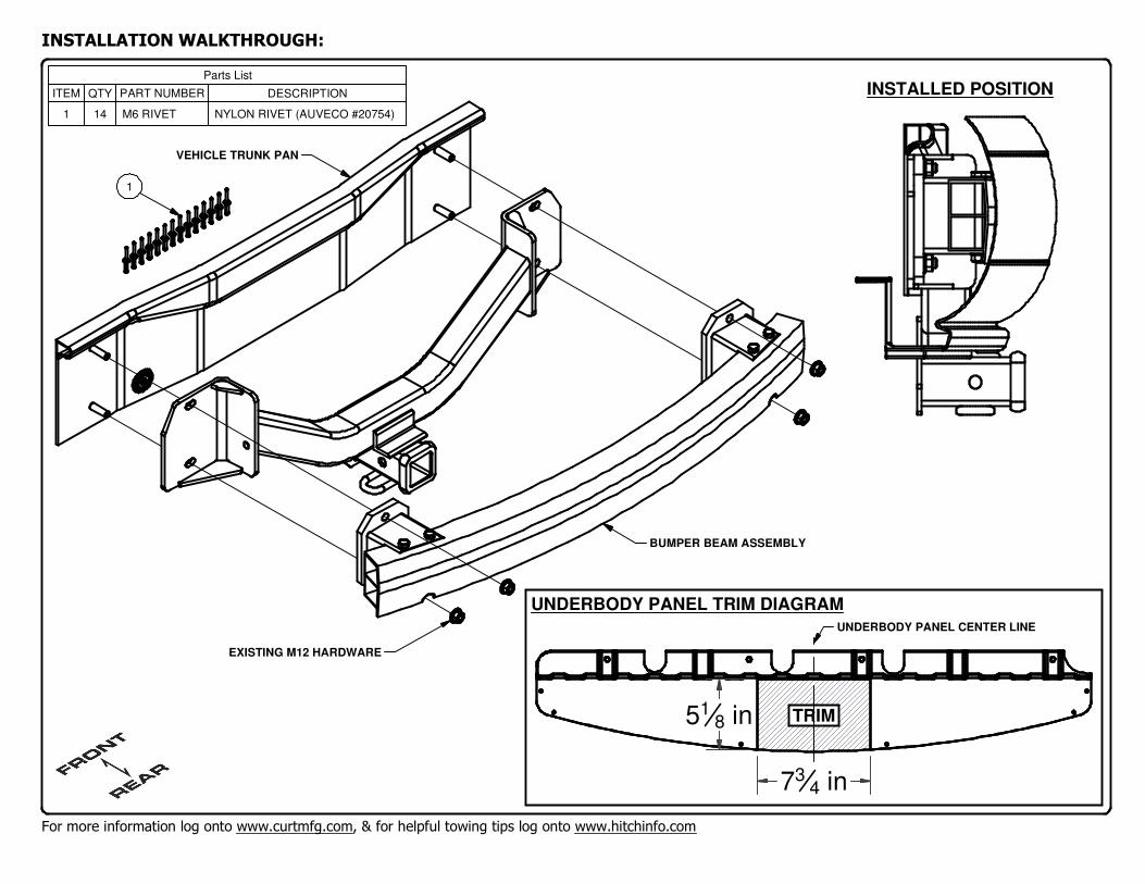
INSTALLATION WALKTHROUGH:
For more information log onto www.curtmfg.com, & for helpful towing tips log onto www.hitchinfo.com
TRIM
UNDERBODY PANEL TRIM DIAGRAM
Parts List
DESCRIPTIONPART NUMBERQTYITEM
NYLON RIVET (AUVECO #20754)M6 RIVET141
INSTALLED POSITION
EXISTING M12 HARDWARE
VEHICLE TRUNK PAN
BUMPER BEAM ASSEMBLY
1
734 in
518 in
UNDERBODY PANEL CENTER LINE
INSTALLATION WALKTHROUGH:
For more information log onto www.curtmfg.com, & for helpful towing tips log onto www.hitchinfo.com
1. Remove underbody panel by removing (11) fasteners.
2. Remove (2) fasteners from bottom of bumper cover and (1) fastener from inside wheel well on each side. These are located behind rear tire.
3. Remove (7) rivets from wheel well trim from above each rear tire. To remove rivets push small center rod though rivet with a small punch or an equivalent tool. Pry rivets from trim and pop trim off. Note: Replacement rivets are included.
4. Remove (2) fasteners from each side of bumper cover which are now accessible due to wheel well trim removal.
INSTALLATION WALKTHROUGH:
For more information log onto www.curtmfg.com, & for helpful towing tips log onto www.hitchinfo.com
5. Pop off plastic covers located to the inside of each tail light.
6. Remove (2) nuts from each tail light. Unplug and remove each tail light.
7. Remove (1) fastener from under each tail light.
8. Pop (2) reflectors off of bumper cover and remove (1) fastener from under each.
h
h

INSTALLATION WALKTHROUGH:
For more information log onto www.curtmfg.com, & for helpful towing tips log onto www.hitchinfo.com
10. Remove (2) inner plastic bodies by removing (4) nuts from each.
9. Carefully remove bumper cover. Pop sides off first and then pull straight back.
11. Remove bumper beam assembly by removing (4) nuts from threaded studs. These nuts will be used to install hitch.
12. Raise hitch and bumper beam into position onto threaded studs and secure to vehicle using the M12 nuts removed in STEP 11.
h

INSTALLATION WALKTHROUGH:
For more information log onto www.curtmfg.com, & for helpful towing tips log onto www.hitchinfo.com
13. Torque all M12 hardware to 86 ft-lbs.
14. Hold inner plastic bodies in position and mark where the hitch side plates interfere. Trim an approximate 3/8" wide by 7/8" deep slot into each inner plastic body to allow for side plate clearance.
15. Reinstall bumper cover and tail lights by reassembling components removed in STEPS 2-10 in reverse order. Note: A plastic rivet gun is required to fasten supplied rivets when reinstalling wheel well trim.
16. Raise underbody panel into position and mark the center using the hitch as a guide. Trim underbody panel. See UNDERBODY PANEL TRIM DIAGRAM on PAGE 2. Reinstall underbody panel and discard extra fastener.
Install is complete.