Embed Size (px)
Citation preview

LINE PROTECTION WITH OVERCURRENT RELAYS 259
Lines are protected by overcurrent-, distance-, or pilot-relaying equipment, depending onthe requirements. Overcurrent relaying is the simplest and cheapest, the most difficult toapply, and the quickest to need readjustment or even replacement as a system changes. Itis generally used for phase- and ground-fault protection on station-service and distributioncircuits in electric utility and in industrial systems, and on some subtransmission lineswhere the cost of distance relaying cannot be justified. It is used for primary ground-faultprotection on most transmission lines where distance relays are used for phase faults, andfor ground back-up protection on most lines having pilot relaying for primary protection.However, distance relaying for ground-fault primary and back-up protection oftransmission lines is slowly replacing overcurrent relaying. Overcurrent relaying is usedextensively also at power-transformer locations for externa-fault back-up protection, buthere, also, there is a trend toward replacing overcurrent with distance relays.
It is generally the practice to use a set of two or three overcurrent relays for protectionagainst interphase faults and a separate overcurrent relay for single-phase-to-ground faults.Separate ground relays are generally favored because they can be adjusted to provide fasterand more sensitive protection for single-phase-to-ground faults than the phase relays canprovide. However, the phase relays alone are sometimes relied on for protection against alltypes of faults. On the other hand, the phase relays must sometimes be made to beinoperative on the zero-phase-sequence component of ground-fault current. These subjectswill be treated in more detail later.
Overcurrent relaying is well suited to distribution-system protection for several reasons. Notonly is overcurrent relaying basically simple and inexpensive but also these advantages arerealized in the greatest degree in many distribution circuits. Very often, the relays do notneed to be directional, and then no a-c voltage source is required. Also, two phase relaysand one ground relay are permissible. And finally, tripping reactor or capacitor tripping(described elsewhere) may be used.
In electric-utility distribution-circuit protection, the greatest advantage can be taken of theinverse-time characteristic because the fault-current magnitude depends mostly on thefault location and is practically unaffected by changes in generation or in the high-voltagetransmission system. Not only may relays with extremely inverse curves be used for thisreason but also such relays provide the best selectivity with fuses and reclosers. However, ifground-fault-current magnitude is severely limited by neutral-grounding impedance, as isoften true in industrial circuits, there is little or no advantage to be gained from the inversecharacteristic of a ground relay.
13LINE PROTECTION WITH OVERCURRENT RELAYS

260 LINE PROTECTION WITH OVERCURRENT RELAYS
Inverse-time relaying is supplemented by instantaneous relaying wherever possible. Speedin clearing faults minimizes damage and thereby makes automatic reclosing more likely tobe successful.
HOW TO SET INVERSE-TIME-OVERCURRENT RELAYS FOR COORDINATION
The first step is to choose the pickup of the relay so that it will (1) operate for all shortcircuits in its own line, and (2) provide back-up protection for short circuits in immediatelyadjoining system elements under certain circumstances. For example, if the adjoiningelement is a line section, the relay is set to pick up at a current somewhat less than itreceives for a short circuit at the far end of this adjoining line section under minimumgenerating–or other–conditions that would cause the least current flow at the relaylocation. This is illustrated in Fig. 1.
For a phase relay, a phase-to-phase fault would be assumed since it causes less current toflow than does any other fault not involving ground. However, a phase relay must not beso sensitive that it will pick up under emergency conditions of maximum load over the linefrom which it receives its current. For a ground relay, a single-phase-to-ground fault wouldbe assumed; load current is not a factor in the choice of a ground-relay’s pickup except ina distribution system where there is ground current normally because of unbalancedloading. If there are two or more adjoining line sections, the fault should be assumed atthe end of the section that causes the least current to flow at the location of the relay beingadjusted.
Because of the effect of parallel circuits not shown, less current will flow at the relaylocation of Fig. 1 if breaker A is closed than if A is open. If satisfactory adjustment can beobtained with A closed, so much the better. However, the relay under consideration isbeing adjusted to operate if breaker B fails to open; it is not generally assumed that breakerA will also fail to open. There may be some occasions when one will wish to assumesimultaneous equipment failures at different locations, but it is not the usual practice.Hence, it is permissible to assume that breaker A has opened, which is usually very helpfuland may even be necessary.
Under certain circumstances, the relay will get less current for a phase-to-phase fault at Cwith breaker D closed and under minimum generating conditions than for the faultlocation shown in Fig. 1 with A open; the relay must be able to operate for this conditionalso.
In order to use the most inverse portion of the relay’s time curves, the pickup in terms ofprimary current should be as high as possible and still be low enough so that the relay willoperate reliably under the minimum fault-current condition. Under such conditions, therelay should operate at no less than about 1.5 times its pickup, but as near to that value asconveniently possible. The reason for this rule is that, closer to the pickup current, thetorque is so low that a small increase in friction might prevent operation or it might
Fig. 1. The fault location for adjusting the pickup for back-up protection.

LINE PROTECTION WITH OVERCURRENT RELAYS 261
increase the operating time too much. It may be that the CT ratio and the relay’s range ofadjustment do not permit adjusting for so low a multiple of pickup; in that event the onlyrecourse, aside from changing the CT or the relay, is to use the highest possible pickup forwhich the relay can be adjusted.
To assure selectivity under all circumstances, the pickup of a given relay should besomewhat higher than that of other relays nearer to the fault and with which the givenrelay must be selective.
Because the impedance of generators increases from subtransient to synchronous as timeprogresses from the instant that a short circuit occurs, the question naturally arises as towhich value of impedance to use in calculating the magnitude of short-circuit current forprotective-relaying purposes where overcurrent relaying is involved. The answer to thisquestion depends on the operating speed of the relay under consideration, on the amountby which generator impedance affects the magnitude of the short-circuit current, and onthe particular relay setting involved. Usually, the impedance that limits the magnitude ofthe short-circuit current contains so much transformer and line impedance that the effectof changing generator impedance is negligible; one can always determine this effect in anygiven application. For relays near a large generating station that furnishes most of theshort-circuit current, synchronous impedance would be best for determining the pickup ofa relay for back-up purposes particularly if the operating time of the relay was to be as longas a second or two. On the other hand, the pickup of a high-speed relay near such agenerating station would be determined by the use of transient–or possibly evensubtransient–impedance. Ordinarily, however, transient impedance will be found mostsuitable for all purposes–particularly for subtransmission or distribution circuits whereovercurrent relays are generally used; there is enough transformer and line impedancebetween such circuits and the generating stations so that the effect of changing generatorimpedance is negligible. In fact, for distribution circuits, it is frequently sufficientlyaccurate to assume a source impedance that limits the current to the source-breakerinterrupting capacity on the high-voltage side of a power transformer feeding such acircuit; in other words, only slightly more total impedance than that of the transformeritself and of the circuit to be protected is assumed.
Whether to take into account the effect of arc and ground resistance depends on what oneis interested in. Arc resistance may or may not exist. Occasionally, a metallic fault with noarcing may occur. When one is concerned about the maximum possible value of faultcurrent, he should assume no arc resistance unless he is willing to chance the possibility offaulty relay operation should a fault occur without resistance. Thus, as will be seen later,for choosing the pickup of instantaneous overcurrent relays or the time-delay adjustmentfor inverse-time relays, it is more conservative to assume no arc resistance.
When one is choosing the pickup of inverse-time relays, the effect of arc resistance shouldbe considered. This is done to a limited extent when one arbitrarily chooses a pickupcurrent lower than the current at which pickup must surely occur, as recommended in theforegoing material; however, this pickup may not be low enough. In view of the fact thatan arc may lengthen considerably in the wind, and thereby greatly increase its resistance,it is a question how far to go in this respect. At least, one should take into account theresistance of the arc, when it first occurs, whose length is the shortest distance betweenconductors or to ground. Beyond this, what one should do depends on the operating time

262 LINE PROTECTION WITH OVERCURRENT RELAYS
of the relay under consideration and the wind velocity. The characteristics of an arc areconsidered later.
Ground resistance concerns us only for ground faults. It is in addition to arc resistance.This subject is considered later also, along with arc resistance.
For ground relays on lines between which there is mutual induction, this mutual inductionshould be taken into account in calculating the magnitude of current for single-phase-to-ground faults. In some studies, this will show that selectivity cannot be obtained when itwould otherwise appear to be possible.
The second step in the adjustment of inverse-time-overcurrent relays is to adjust the timedelay for obtaining selectivity with the relays of the immediately adjoining systemelements. This adjustment should be made for the condition for which the maximumcurrent would flow at the relay location. This condition would exist for a short circuit justbeyond the breaker in an adjoining system element. This is illustrated in Fig. 2. Undercertain circumstances, more current will flow at the relay location if breaker 3 is open. Foradjusting a phase relay, a three-phase fault would be assumed; and for a ground relay asingle-phase-to-ground fault would be assumed. In either event, one would use the faultcurrent for maximum generating conditions and for any likely switching condition thatwould make the current at 1 most nearly equal to the current at 2. For example, when thereare other sources of ahort-circuit current connected to bus A, if it is considered a practicaloperating condition to assume them to be disconnected, they should be so assumed.
The adjustment for selectivity is made under maximum fault-current conditions because,if selectivity is obtained under such conditions, it is certain to be obtained for lowercurrents. This will be seen by examining the time-current curves of any inverse-timeovercurrent relay, such as Fig. 3 of Chapter 3, and observing that the time spacing betweenany two curves increases as the multiple of pickup decreases. Hence, if there is sufficienttime spread at any given multiple of pickup, the spread will be more than sufficient at alower multiple. The foregoing assumes that relays having the same time-currentcharacteristics are involved. Relays with different characteristics are to be avoided.
This brings us to the question of how much difference there must be between the operatingtimes of two relays in order that selectivity will be assured. Let us examine the elementsinvolved in the answer to this question by using the example of Fig. 2. For the fault asshown in Fig. 2, the relay located at breaker 2 must close its contacts, and breaker 2 musttrip and interrupt the flow of short-circuit current before the relay at breaker 1 can close itscontacts. Furthermore, since the relay at breaker 1 may “overtravel” a bit after the flow ofshort-circuit current ceases, provision should also be made for this overtravel.
Fig. 2. The fault location for adjusting for selectivity.

LINE PROTECTION WITH OVERCURRENT RELAYS 263
We can express the required operating time of the relay at 1 in terms of the operating timeof the relay at 2 by the following formula:
T1 = T2 + B2 + O1 + F
where T1 = operating time of relay at 1.
T2 = operating time of relay at 2.
B2 = short-circuit interrupting time of breaker at 2.
O1 = overtravel time of relay at 1.
F = factor-of-safety time.
The overtravel time will be different for different overcurrent relays and for differentmultiples of pickup, but, for the inverse-time types generally used, a value of about 0.1second may be used. The factor-of-safety time is at the discretion of the user; this timeshould provide for normally expected variations in all the other times. A value of 0.2 to 0.3second for overtravel plus the factor of safety will generally be sufficient; lower values maybe used where accurate data are available.
We are now in a position to examine Fig. 3 where in time-versus-distance curves are shownfor relays that have been adjusted as described in the foregoing. The time S, called the“selective-time interval,” is the sum of the breaker, over travel, and factor-of-safety times. Avertical line drawn through any assumed fault location will intersect the operating-time
curves of various relays and will thereby show the time at which each relay would operateif the short-circuit current continued to flow for that length of time.
The order in which the relays of Fig. 3 are adjusted is to start with the relay at breaker 1and work back to the relay at breaker 4. This will become evident when one considers thatthe selectivity adjustment of each relay depends on the adjustment of the relay with whichit must select. For cases like that shown in Fig. 3, we can generalize and say that one startsadjustment at the relay most distant electrically from the source of generation, and thenworks back toward the generating source.
ARC AND GROUND RESISTANCE
Although there is much difference of opinion on the interpretation of test data, themaximum value of rms volts per foot of arc length given by any of the data1,2,3 for all arccurrents greater than l000 rms amperes is about 550. For currents below l000 amperes, the
Fig. 3. Operating time of overcurrent relays with inverse-time characteristics.

264 LINE PROTECTION WITH OVERCURRENT RELAYS
formula V = 8750/I 0.4 gives the maximum reported value of rms volts per foot (V) for anyrms value of arc current (I); from this formula, values considerably higher than 550 will beobtained at low currents. Actually, this formula gives a fairly good average of all theavailable data for any value of arc current, as will be seen by plotting superimposed thedata of Fig. l of Reference 1, Fig. 5 of Reference 2, and the foregoing formula which isobtained from the formula given in Reference 3. However, because this average value isonly about half of the maximum reported in Reference l for currents larger than l000amperes, it is more conservative not to use this average for such current values when oneis interested in the maximum arc resistance.
To take into account the lengthening of the arc by wind, the approximate formulaL = 3vt + L0 may be used, where:
L = length of arc, in feet.
v = wind velocity, in miles per hour.
t = time, in seconds after the arc was first struck.
L0 = initial arc length, i.e., the shortest distance between conductorsor across insulator, in feet.
It will be evident that there are limits to which this formula may be applied because thereare limits to the amount an arc may stretch without either restriking or being extinguished.Reference 2 gives several sets of data showing how the arc voltage increased during fieldtests.
Ground resistance is resistance in the earth. This resistance is in addition to that of an arc.When overhead ground wires are not used, or when they are insulated from the towers orpoles, the ground resistance is the tower- or pole-footing resistance at the location wherethe ground fault has occurred plus the resistance of the earth back to the source. Electricutilities have measured data on such footing resistance. When overhead ground wires areconnected to steel towers or to grounding connections on wood poles, the effect issomewhat as though all footing resistances were connected in parallel, which makes theresulting footing resistance negligible. Published zero-phase-sequence-impedance data donot include the effect of tower-footing resistance.
Occasionally, a conductor breaks and falls to the ground. The ground-contact resistance ofsuch a fault may be much higher than tower-footing resistance where relatively lowresistance is usually obtained with ground rods or counterpoises. The contact resistancedepends on the geology of a given location, whether the ground is wet or dry, and, if dry,how high the voltage is; it takes a certain amount of voltage to break down the surfaceinsulation.
Ground resistance can range over such wide limits that the only practical thing to do is touse measured values for any given locality. An example of extremely high groundresistance and the method of relaying is given in Reference 4.
In one system,5 advantage was taken of ground resistance to decrease the rms magnitudeof ground-fault current and to greatly shorten the time constant of its d-c component inorder to reduce the interrupting stress on circuit breakers. However, such practice shouldbe avoided in general.

LINE PROTECTION WITH OVERCURRENT RELAYS 265
EFFECT OF LOOP CIRCUITS ON OVERCURRENT-RELAY ADJUSTMENTS
Figure 3 best serves the purpose of illustrating how selectivity is provided with inverse-time-overcurrent relays. But, lest it mislead one by oversimplifying the problem, it is well torealize that, except for some parts of distribution systems, Fig. 3 does not truly representmost actual systems where loops are the rule and radial circuits are the exception. Theprinciples involved and the general results obtained in the application and adjustment ofovercurrent relays are correctly shown by reference to Fig. 3, but the difficulties in arrivingat suitable adjustment in an actual system are minimized. This consideration is importantbecause it is often the deciding factor that leads one to choose distance or pilot relaying inpreference to overcurrent relaying.
When we studied the method of setting inverse-time-overcurrent relays, we saw that therelay most distant electrically from the generating source was adjusted first, and that onethen worked back toward the generating source. The same procedure would be followedin the simple loop system illustrated in Fig. 4. The order in which the relays “looking” oneway around the loop would be adjusted is 1-2-3-4-5, and looking the other way, a-b-c-d-e.Directional overcurrent relays would usually be employed as indicated by the single-endedarrows that point in the direction of fault-current flow for which the relays should trip.Only at locations e and 5 can fault current flow only in the same direction as that for whichtripping is desired, and the relays there may be non-directional as indicated by the double-headed arrows. The first relay to be adjusted in each of the two groups can be made assensitive and as fast as possible because the current flow at the relay location will decreaseto zero as faults are moved from the relay location to the generator bus, and hence thereis no problem of selectivity for those relays. The phase relay at 1, for example, must receiveat least 1.5 times its pickup current for a phase-to-phase fault at the far end of its line withthe breaker at e open, and with minimum generation. Of course, no phase overcurrentrelay should be so sensitive that it will pick up on maximum load.
Occasionally, the short-circuit current that can flow in the non-tripping direction is sosmall in comparison with the current that can flow in the tripping direction that certainrelays need not be directional, the system itself having a directional characteristic. But, ifa relay can pick up on the magnitude of current that flows in the non-tripping direction,it is wise to make the relay directional or else the problem of obtaining selectivity under allpossible conditions is needlessly complicated; and a future change in the system or itsoperation may demand directional relays anyway.
The first complication in adjusting overcurrent relays in loop circuits arises whengenerators are located at the various stations around the loop. The problem then is where
Fig. 4. The order for adjusting relays in a simple loop system.

266 LINE PROTECTION WITH OVERCURRENT RELAYS
to start. And, finally, when circuits of one loop form a part of other loops, the problem ismost difficult. The trial-and-error method is the only way to proceed with such circuits. Infact, some such systems cannot be relayed selectively by inverse-time-overcurrent relayswithout operating the system with certain breakers normally open, and closing them onlyin emergencies. Supplementary instantaneous overcurrent relaying will sometimes giverelief in such cases, as will be described later. Of course, such systems are not created intheir entirety; they develop slowly, and the relaying problems arise each time that a changeis made.
EFFECT OF SYSTEM ON CHOICE OF INVERSENESS OF RELAY CHARACTERISTIC
The less change there is in the magnitude of short-circuit current with changes inconnected generating capacity, etc., for a fault at a given location, the more benefit can beobtained from greater inverseness. This is particularly true in distribution circuits whereshort-circuit-current magnitude is practically independent of normal changes ingenerating capacity. In such circuits one can use the very inverse–or extremely inverseovercurrent relays to advantage.
In systems, such as many industrial systems, where the magnitude of the ground-faultcurrent is severely limited by neutral-grounding impedance, little or no advantage can betaken of the inverseness of a ground-relay’s characteristic; the relays might just as well havedefinite-time characteristics. This would also be true even where no neutral impedance wasused if the sum of the arc and ground resistance was high enough, no matter where thefault should happen to occur.
Later, under the heading “Restoration of Service to Distribution Feeders after ProlongedOutages,” the need for the extremely inverse characteristic is described. This characteristicis also useful in areas of a distribution system adjacent to where fuses and reclosers beginto replace relays and circuit breakers, because the extremely inverse characteristic willcoordinate with fuses and reclosers.
THE USE OF INSTANTANEOUS OVERCURRENT RELAYS
Instantaneous overcurrent relays are applicable if the fault-current magnitude undermaximum generating conditions about triples as a fault is moved toward the relay locationfrom the far end of the line. This will become evident by referring to Fig. 5 where thesymmetrical fault-current magnitude is plotted as a function of fault location along a linefor three-phase faults and for phase-to-phase faults, if we assume that the fault-currentmagnitude triples as the fault is moved from the far end of the line to the relay location.The pickup of the instantaneous relay is shown to be 25% higher than the magnitude ofthe current for a three-phase fault at the end of the line; the relay should not pick up atmuch less current or else it might overreach the end of the line when the fault-currentwave is fully offset. In a distribution circuit, the relay could be adjusted to pick up atsomewhat lower current because the tendency to overreach is less. For the condition of Fig.5, it will be noted that the relay will operate for threephase faults out to 70% of the linelength and for phase-to-phase faults out to 54%. If the ground-fault current is not limitedby neutral impedance, or if the ground resistance is not too high, a similar set ofcharacteristics for ground faults would probably show somewhat more than 70% of the line

LINE PROTECTION WITH OVERCURRENT RELAYS 267
protected; this is because the ground-fault current usually increases at a higher rate as thefault is moved toward the relay. The technique of Fig. 5 may be used for any otherconditions to determine the effectiveness of instantaneous overcurrent relaying, includingthe effect on fault-current magnitude because of changes in generation, etc.
The shaded area of Fig. 6 shows how much instantaneous overcurrent relaying reduces theover-all relaying time for most faults. Even if such reduction is obtained only undermaximum generating conditions, and if instantaneous relays were not even operableunder minimum generating conditions, the use of supplementary instantaneous relays isconsidered to be worth while because they are relatively so inexpensive.
With instantaneous overcurrent relaying at both ends of a line, simultaneous tripping ofboth ends is obtained under maximum generating conditions for faults in the middleportion of the line. For faults near the ends of the line, sequential instantaneous trippingwill often occur, i.e., the end nearest the fault will trip instantly and then the magnitude ofthe current flowing to the fault from the other end will usually increase sufficiently to pickup the instantaneous overcurrent relays there.
When the magnitude of fault current depends only on the fault location, instantaneousovercurrent relaying is like distance relaying6 except that the overcurrent relays cannotgenerally be as sensitive as distance relays.
Fig. 5. Performance of instantaneous overcurrent relays.
Fig. 6. Reduction in tripping time by the use of instantaneous overcurrent relays.

268 LINE PROTECTION WITH OVERCURRENT RELAYS
AN INCIDENTAL ADVANTAGE OF INSTANTANEOUS OVERCURRENT RELAYING
A useful advantage that can sometimes be taken of instantaneous overcurrent relaying isillustrated in Fig. 7. Without instantaneous overcurrent relaying at breaker 2, the inverse-time-overcurrent relays at 1 would have the dashed time curve so as to obtain the selectivetime interval ab with respect to the inverse-time relays at breaker 2. With instantaneousovercurrent relays at 2, the inverse-time relays at 1 need only be selective with the inverse-time relays at 2 for faults at and beyond the point where the instantaneous relays stop
operating, as shown by cd. This permits speeding up the relays at 1 from the dashed to thesolid curve, which is sometimes very useful, or even necessary when complicated loopcircuits are involved. Of course, under minimum generating conditions when theinstantaneous relays may not operate, one must be sure that selectivity between the inverse-time relays is obtained. The fact that selectivity is not obtained between the inverse-timerelays for faults just beyond the relay at 2 for maximum generating conditions isunimportant so long as selectivity is obtained down to the pickup current of theinstantaneous relays.
Fig. 7. Illustrating an additional advantage of instantaneous overcurrent relays.

LINE PROTECTION WITH OVERCURRENT RELAYS 269
OVERREACH OF INSTANTANEOUS OVERCURRENT RELAYS
“Overreach” is the tendency of a relay to pick up for faults farther away than one wouldexpect if he neglected the effect of offset in the fault-current wave. Magnetic-attractionrelays are more affected by offset waves than induction relays, and some induction relaysare more affected than others. Certain induction relays can be designed to be unaffectedby offset waves.
“Percent overreach” is a term that describes the degree to which the overreach tendencyexists, and it has been defined as follows:
A – BPercent overreach = 100 –––—( )A
where A = the relay’s pickup current, in steady-state rms amperes.
B = the steady-state rms amperes which, when fully offset initially, will just pick up the relay.
In relays that have a tendency to overreach, the percent overreach increases as the ratio ofreactance to resistance of the fault-current-limiting impedance increases, or, in otherwords, as the time constant of the d-c component of the fault current increases. The slower
the decay of the d-c component, the sooner will the integrated force acting on the relaycause it to pick up; and the sooner the relay tends to pick up, the lower may be the rmscomponent of the fault current and still cause pickup. If the fault-current wave werecontinually fully offset, the rms component for pickup would be the smallest. It may beevident from the foregoing that, other things being equal, the faster a relay is, the greaterwill its percent overreach be. The maximum percent overreach would be 50% for a relaythat was fast enough to respond to the instantaneous magnitude of current. Since the rmsvalue of a fully offset sine wave is √
–3 times that if the wave were symmetrical, the maximum
value of percent overreach is 42% for relays that are not fast enough to respond to theinstantaneous magnitude of current. Figure 8 shows how the percent overreach of acertain relay increases as the system angle (tan-1 X/R) increases. Because X/R in adistribution circuit is only about 1 or 2, the tendency to overreach is negligible.
Fig. 8. Overreach characteristic of a certain instantaneous overcurrent relay.

270 LINE PROTECTION WITH OVERCURRENT RELAYS
To allow accurately for overreach when choosing the pickup of an instantaneousovercurrent relay, one must have a percent-overreach curve for the relay, like that of Fig. 8.Then, solving the foregoing equation for A, we obtain:
l00BA = ———————————
(100 – Percent overreach)
Thus, with an overcurrent relay that has a 15% overreach for a fault whose steady-statecomponent of current is 10 amperes, if the relay is not to operate for that fault, A mustexceed:
100 × 10———— amperes = 11.8 amperes100 – 15
When percent-overreach data are not available, it will usually be satisfactory to make thepickup about 25% higher than the maximum value of symmetrical fault current for whichthe relay must not operate. This will provide for overreach and also for some error in thedata on which the setting is based.
The tendency of an instantaneous overcurrent relay to overreach on offset waves can beminimized by a so-called “transient shunt.” 7 This device is described in Chapter 14 inconnection with its use with distance relays for the same purpose.
THE DIRECTIONAL FEATURE
Overcurrent relaying is made directional to simplify the problem of obtaining selectivitywhen about the same magnitude of fault current can flow in either direction at the relaylocation. It would be impossible to obtain selectivity under such circumstances ifovercurrent relays could trip their breakers for either direction of current flow. Thedirectional feature is not needed for a radial circuit with a generating source at only oneend. Nor is it required where short-circuit current can flow in either direction if themagnitude of current that can flow in the tripping direction is several times that in theother direction; here, the system has a sufficiently directional characteristic. However, it isbest to install directional relays, even if the directional feature is not presently needed,because system changes are likely to make directional relays necessary.
All directional-overcurrent relays should have the directional-control feature, as describedin Chapter 3, whereby the overcurrent unit cannot begin to operate until the directionalunit operates for current flow in the direction for which the overcurrent unit shouldoperate. Here, again, this feature is not always required, but need for it may develop in thenear future.
Occasionally, voltage-restrained directional units are desirable for use with phaseovercurrent relays. This need arises when the magnitude of fault current in the directionfor which an overcurrent relay must trip its breaker can be about the same as–or evensomewhat less than–the maximum load current that might flow in the same direction.Voltage-restrained directional units also minimize the likelihood of undesired trippingwhen severe power swings occur. Such directional units should also provide directionalcontrol.

LINE PROTECTION WITH OVERCURRENT RELAYS 271
The terms “directional-overcurrent” and “directional-ground,” as applied to ground relayswith directional characteristics, are used by some people to denote two different types ofrelays. The term “directional-overcurrent” denotes a relay with separate directional andovercurrent units, and the term “directional-ground” denotes a directional unit withadjustable pickup and time-delay characteristics that combines the directional andovercurrent functions. The directional� type is generally preferred because, although itimposes somewhat more burden on its CT’s and also takes up somewhat more panel space,it is much easier to adjust. This is because only the line-current magnitude affects itsoperation both as to sensitivity and time delay; its directional unit is so sensitive and fastthat its effect may be ignored. The sensitivity and speed of the directional-ground type is afunction of the product of the line current, the polarizing current or voltage, and thephase angle between them. The two types are not simply interchangeable, and it is best tostandardize on one or the other and not to mix them in a system, or else selectivity may bejeopardized.
USE OF TWO VERSUS THREE RELAYS FOR PHASE-FAULT PROTECTION
The consideration of two versus three relays for phase-fault protection arises because of adesire to save the expense of one CT and one relay, or at least of one relay, in applicationswhere only the bare minimum expense can be tolerated for the protection of a certain line.The considerations involved in such practices are as follows.
Non-Directional Relaying. Non-directional-overcurrent phase-fault relaying can be providedby two relays energized from CT’s in two of the three phases. However, protection will notnecessarily be provided if the CT’s in all circuits are not located in the same phases, asillustrated in Fig. 9. The system shown in Fig. 9 is assumed to be ungrounded.Simultaneous ground faults on different phases of two different circuits will constitute aphase-to-phase fault on the system, and yet neither overcurrent relay will operate.
Fig. 9. A case of lack of protection with two overcurrent relays.

272 LINE PROTECTION WITH OVERCURRENT RELAYS
Whether the system neutral is grounded or not, complete protection against phase andground faults, even in the situation of Fig. 9. is provided if three CT’s are used with twophase relays and one ground relay as illustrated in Fig. 10.
If a wye-delta or a delta-wye power-transformer bank lies between the relays and a phase-to-phase fault, the magnitude of the current in one of the phases at the relay location will betwice as great as in either of the other two phases. If only two relays are used, neither relaywill get this larger current for a fault between one pair of the three possible pairs of phasesthat may be faulted on the other side of thebank. This fact should be taken into accountin choosing the pickup and time settings.
If the fault-current magnitude for a phase-to-phase fault is of the same order as the loadcurrent, the effect of load current adding tofault current in one phase and subtractingfrom it in another phase should beconsidered. This affects the pickup and timesettings in a manner similar to that of anintervening power-transformer bank.
Three CT’s and three phase relays are usedwherever economically justifiable to avoid the foregoing difficulties because at least onerelay will always operate for all interphase faults; and, except for the special conditions justdescribed, two relays will operate, thereby giving double assurance of protection for muchless than double the cost.
Directional Relaying. Directional-overcurrent phase-fault relaying is subject to theconsiderations described for non-directional-overcurrent relaying in so far as overcurrentunits are concerned. In addition, there are the following considerations.
In a non-grounded system, two single-phase relays may generally be used if one is sure thatthe relays of all circuits are energized by currents from the same phases. Otherwise,grounds could occur on different phases of two different circuits, as in Fig. 9, therebyimposing a phase-to-phase fault on the system, and no protection would be provided.Directional-overcurrent relays for ground-fault protection are not usable on non-groundedsystems, and, therefore, they could not alleviate this possible difficulty in the same way thatnon-directional ground-overcurrent relays do.
If directional phase relaying is to be used in two phases of a grounded-neutral system,ground relays must be provided for protection against ground faults. Then, the onlyquestion is if one or the other of the two phase relays will always operate for a phase-to-phase fault in the tripping direction.
If the magnitude of fault current for phase-to-phase faults is not several times the load-current magnitude, three single-phase directional-overcurrent relays should be used toassure tripping when desired. However, this problem involves more than just the numberof relays required; the relays may operate to trip undesirably as well as to fail to trip whendesired. Therefore, not only are three relays necessary but also voltage restraint on thedirectional units to keep them from operating undesirably. If three relays were not required
Fig. 10. Complete protection with two phaserelays and one ground relay.

LINE PROTECTION WITH OVERCURRENT RELAYS 273
for other reasons, they would be required as soon as voltage restraint is used. (This is whyit is never the practice to use only two distance relays.)
With only two directional-overcurrent relays, the quadrature connection should be used.This is the best assurance that one of the two relays will always operate under theborderline conditions existing when faults occur close to the relay location.
SINGLE-PHASE VERSUS POLYPHASE DIRECTIONAL-OVERCURRENT RELAYS
Single-phase directional-overcurrent relays are generally preferred for protection againstinterphase faults. The main reason for this is that the very desirable feature of “directionalcontrol” is more simply and reliably obtained with single-phase directional-overcurrentrelays than with a polyphase directional relay in combination with single-phaseovercurrent relays. The directional-unit contact of a single-phase directional-overcurrentrelay controls the operation of the overcurrent unit directly; an intermediate auxiliary relayis required when a polyphase directional unit is used.
Single-phase directional-overcurrent relays must be used when a-c tripping is involved,because separate contacts must be available for connection in each of the three CTsecondary circuits. An auxiliary relay cannot be used with a polyphase directional relay toget the necessary contact separation, because there is no suitable voltage source to operatethe auxiliary relay; the lack of such a voltage source is why a-c tripping is used.
A set of three single-phase directional-overcurrent relays can often be used to provideprotection against single-phase-to-ground faults as well as against interphase faults.Polyphase directional relays may not be used for this purpose unless the minimum ground-fault current is more than 3 times the maximum load current.
Some users want to test the relays of each phase separately so that, if a fault occurs duringtesting, the relays of the other two phases can provide protection. This requires single-phase relays.
A minor advantage of single-phase relays is that they provide somewhat more flexibility inthe layout of panels.
The advantage of a polyphase directional relay is that it is less subject to occasionalmisoperation than single-phase relays. For a certain fault condition, one of three single-phase relays may develop torque in the tripping direction when tripping would beundesirable; if the current in that one relay was high enough to operate the overcurrentunit, improper tripping would result. Since a polyphase directional relay operates on thenet torque of its three elements, a reversed torque in one element can be overbalanced bythe other two elements, and a correct net torque usually results. The subject of directional-relay misoperation is treated in the following section.
HOW TO PREVENT SINGLE-PHASE DIRECTIONAL OVERCURRENT-RELAYMISOPERATION DURING GROUND FAULTS
Under certain circumstances, single-phase directional-overcurrent relays for phase-faultprotection may cause undesired tripping for ground faults in the non-tripping direction.

274 LINE PROTECTION WITH OVERCURRENT RELAYS
Such undesired tripping can be prevented if one only knows when special preventivemeasures are necessary.
The zero-phase-sequence components of ground-fault current produce the misoperatingtendency. All these components are in phase, and, when wye-connected currenttransformers are used, these components always produce contact-closing torque in one ofthe three directional units no matter in which direction the current may be flowing.Generally, the other fault-current components are able to “swamp” the effect of the zero-phase-sequence components. But, when the fault current is largely composed ofzero-phase-sequence component, misoperation is most likely.
Figure 11 shows the basic type of application where undesired tripping is most apt to occur.Let us assume that the directional units of the relays are intended to permit tripping onlyfor faults to the left of the relay location, as indicated by the arrow. However, a ground faultto the right, as shown, will cause at least one directional unit to close its contact and permittripping by its overcurrent unit. Whether the overcurrent unit will actually trip its breakerwill depend on its pickup and time settings, and on whether it gets enough current tooperate before the fault is removed from the system by some other relay that is supposed tooperate for this fault. Failure to trip when tripping is desired is not a problem.
Misoperation can occur also for conditions approaching those of Fig. 11.8 In other words,misoperation may still occur if there is a small source of generation at the load end of Fig.11. In general, one should examine the possibility of misoperation whenever the zero-phase-sequence impedances from the ground-fault location back to the sources ofgeneration on either side of the fault are not approximately in the same complex ratio asthe corresponding positive-phase-sequence impedances. Thus, in addition to the situationof Fig. 11, if one side of a system is grounded through resistance and the other sidethrough reactance, misoperation is possible.
The likelihood of misoperation is greatest when the phase relays are used also for ground-fault protection, and particularly when the relays have to be more sensitive because theground-fault current is limited by neutral impedance.
To prevent misoperation for the situation shown in Fig. 11, the phase relays should beprevented from responding to the zero-phase-sequence component of current. This can bedone with a zero-phase-sequence shunt using three auxiliary current transformers, asshown in Fig. 12. It is emphasized that the neutral of the phase relays should not beconnected to the CT neutral or else part of the effectiveness of the shunt will be lost. Delta-connecting the secondaries of the main current transformers would also remove thezero-phase-sequence component, but it introduces other misoperating tendencies, and it
Fig. 11. A situation where single-phase directional-overcurrent relays may misoperate.

LINE PROTECTION WITH OVERCURRENT RELAYS 275
does not provide the required source of energization for ground relays. The 90-degree orquadrature connection of the phase relays should be used.
The phase relays will still be able to respond to ground faults if the current magnitude islarge enough, and if positive-phase-sequence components are present in the fault current.However, it is generally preferable to use separate directional-overcurrent ground relays forground-fault protection because faster tripping can thereby be obtained. Where only zero-phase-sequence current can flow, as at the relay location of Fig. 11, separate ground relaysmust be used.
ADJUSTMENT OF GROUND VERSUS PHASE RELAYS
The satisfactory adjustment of ground overcurrent relays is generally easier to achieve thanthat of phase overcurrent relays in any system, including complicated loop systems. Theprincipal reason for this is that the zero-phase-sequence impedance of lines (except single-phase cables) is approximately 2 to 5.5 times the positive-phase-sequence impedance,which provides two beneficial effects: (1) the magnitude of zero-phase-sequence currentvaries much more with fault location, and (2) the magnitude of the zero-phase-sequencecurrent is not so much affected by changes in generating capacity.
These effects make it possible to take greater advantage of the inverse-time characteristic,and particularly of the very inverse characteristic; and also they aid the application ofinstantaneous overcurrent relays. Another simplification with ground relaying is that thepickup does not have to be higher than load current, because ground relays are notenergized during normal load conditions, except in some distribution systems whereground current flows normally because of unbalanced phase-to-ground loading. (Forother reasons to be discussed later there are limits as to how sensitive ground relays maybe.) Finally, two-winding wye-delta or delta-wye power transformers are open circuits in thesystem so far as ground relays are concerned; in other words, except for the effect of CT
Fig. 12. Application of a zero-phase-sequence-current shunt.

276 LINE PROTECTION WITH OVERCURRENT RELAYS
errors, a ground-overcurrent relay cannot reach through such a transformer for any kindof fault on the other side. This minimizes the selectivity problem because it restricts the“reach” of the ground relays. The foregoing are the reasons why, when it is necessary to usedistance relays for interphase faults, inverse-time and instantaneous overcurrent relayingare often satisfactory for ground faults.
An excellent coverage of the whole subject of ground-fault protection of transmission linesis in Reference 9.
EFFECT OF LIMITING THE MAGNITUDE OF GROUND-FAULT CURRENT
Current-limiting impedance in the grounded neutrals of generators or power transformersmay be desirable from the standpoint of limiting the severity of a phase-to-ground shortcircuit. If carried too far, however, such practice tends to jeopardize the application ofground relaying where fast and selective operation is required.
Two problems must be considered. The first problem is that of obtaining sufficientsensitivity without danger of misoperation because of CT errors when large phase-faultcurrents flow. As explained later, an overcurrent relay in the neutral of wye-connected CT’swill receive a current, even though a fault may not involve ground, if residual flux or d-coffset current in a CT of one phase causes it to have a different ratio error from a CT inanother phase during a fault that involves large phase currents. The more sensitive theground relay has to be in order to operate on the severely restricted phase-to-ground-faultcurrents, the more likely it is to operate on this CT error current.
The second problem when ground-fault current is limited by neutral impedance is toobtain prompt and selective tripping. The effect of limiting the ground-fault current byneutral impedance is to reduce the difference in magnitude of ground-fault current forfaults at different locations. If there is little or no difference in the fault current for nearbyor for distant faults, the inverse-time characteristic is of little use. The result is thatselectivity must be obtained on the basis of time alone. Where several line sections are inseries, the tripping time must be increased a fixed amount for each line section, the nearera fault is to the source of fault current. As a consequence, faults adjacent to the source maynot be cleared in less than several seconds, and during such a relatively long time the faultmight involve other phases, thus causing a severe shock to the system.
It has been found from experience that a good rule of thumb is not to limit the ground-fault current of the generator or transformer to less than about its rated full-load current.Even this might be objectionable on some systems. The best procedure is to study the effectof limiting the current in each individual case.
Ground relays that are much more sensitive than phase relays may misoperate whensimultaneous grounds exist at two different locations on different phases. Actually, thisconstitutes a phase-to-phase fault on the system, and the fault-current magnitude will bethat for phase-to-phase faults. However, the ground relays of the circuits having these faultswill operate as though a ground fault existed but at much higher speed than they wouldoperate for ground faults because the current is 90 much higher. It is possible that theseground relays may operate faster than the phase relays that should operate, and the wrongbreakers might be tripped because the ground relays might not be selective with each otherat these higher currents10

LINE PROTECTION WITH OVERCURRENT RELAYS 277
TRANSIENT CT ERRORS
The principal problem introduced by transient CT errors is the effect on fast and sensitiveovercurrent ground relays. The troublesome effect, often called “false residual current,” isthat large transient currents flow through the ground-relay coils in the CT neutral whenthere is no actual ground-fault current in the CT primaries. This happens because the CT’s
have different errors because of unequal d-c offset in the primary currents or because ofdifferent amounts of residual magnetism. As a consequence, if ground-fault current isseverely limited by neutral impedance and one needs to use very sensitive ground relays todetect ground faults reliably, the relays should have time delay or else they may operateundesirably on high-current interphase faults.
Such false residual current can be reduced appreciably by the addition of resistance to theCT neutral circuit if the relay burden is not already high enough to limit the current. Thesame mechanism applies as with current-differential relaying for bus protection, describedin Chapter 12. The addition of such resistance tends to equalize the CT errors. However,the best solution is a CT whose magnetic circuit encircles all three phase conductors.11
Although not properly includable as consequences of transient CT errors, many othertransient and steady-state conditions may cause ground-relay misoperation. Two ofthese–open phases and simultaneous ground faults at different locations–are describedfurther in this chapter. The others are comprehensively treated in Reference 12. For these,as well as for transient CT errors, a solution that usually works is to make the ground relaysless sensitive.
When none of the suggested solutions to false residual current can be used, it is possible toprovide equipment that will permit a ground relay to close a circuit only if fault current isflowing in only one phase, such as, for example, by the relay described in Reference 13.However, this may be too heroic a solution for a distribution circuit.
Fig. 13. Illustrating the possibility of ungrounded-neutral operationwith a ground fault on the line.

278 LINE PROTECTION WITH OVERCURRENT RELAYS
DETECTION OF GROUND FAULTS IN UNGROUNDED SYSTEMS
The operation of other than distribution systems completely ungrounded is recognized aspoor practice, and hence ground relaying in such systems is not usually a consideration.However, through circumstance, a portion of a system containing a source of generationmay become disconnected from the rest of the system, and a condition of ungroundedoperation may result. Consider the situation of Fig. 13 which is encountered quitefrequently. Figure 13 shows a delta-wye power transformer tapped to a transmission line. Asingle-phase-to-ground faulton the line would cause theprompt trippingof breakersAand B.
If we assume that breaker C did not trip by the operation of its phase relays before breakersA and B had tripped, the line section would still be left connected to the tapped stationwith no means for opening breaker C. So long as thefault remainedsingle-phase-to-ground,there would be no current of short-circuit magnitude flowing at C after breakers A and Bhad opened; only charging currents would flow. But, if the fault was of a persistent nature,as, for example, if a conductor had fallen to the ground, it is highly desirable that breakerC open automatically.
The presence of a ground fault on an ungrounded-neutral system can be detected throughthe use of a wye-broken-delta potential transformer with an overvoltage relay connectedacross the opening in the delta, as illustrated in Fig. 14, or the wye windings of Fig. 14 maybe connected to the system indirectly through the secondary of a wye-wye potentialtransformer, both of whose neutrals are grounded.
This potential-transformer connection will be recognized as being that described inChapter 8 for obtaining a polarizing voltage for ground directional relays. When such aconnection is used on an ungrounded system, the burden placed across the break in thedelta should be greater than a certain minimum value, or else an unstable neutral condition(ferroresonance) may develop that would indicate the presence of a ground fault when nofault existed.14 However, it has been found that occasionally the required burden is higherthan that recommended in Reference 14, and is so high that it will quickly thermally
Fig. 14. A wye-broken-delta potential-transformer connection to detect a ground fault on anungrounded-neutral system.
LINE PROTECTION WITH OVERCURRENT RELAYS 279
overload the potential transformers. A promising solution in such cases appears to be aresistor in series with the grounded neutral of the wye windings, as shown in Fig. 14.
An alternative to Fig. 14 is one high-voltage potential transformer connected between onephase and ground, and one induction-type voltage relay with double-throw contacts. Forthis method to work, it is necessary that there be sufficient and well-enough-balancedcapacitance to ground to establish the neutral of the three-phase system approximately atground potential. The relay would be provided with a stiff enough control spring so thatneither contact would be closed under normal-voltage conditions. Should a ground faultoccur on the phase to which the potential transformer was connected, the voltage on therelay would drop and the relay would close its under voltage “b” contact. Should a groundfault occur on either of the other two phases, the relay voltage would rise and cause theovervoltage “a” contact to close. With such a relay arranged to trip a breaker on the closingof either contact, some provision must be made to permit reclosing the breaker if suchreclosing is desired even though voltage has not been restored to the circuit to which thepotential transformer is connected. Here, as in Fig. 14, sufficient stabilizing load should beconnected to the potential-transformer secondary or inserted in series with the primary toprevent ferroresonance.15 If a capacitance potential device were used, it would avoid thisferroresonance problem.
EFFECT OF GROUND-FAULT NEUTRALIZERS ON LINE RELAYING
Ground-fault neutralizers, or “Petersen coils,” do not affect the choice of phase relays forline protection. When provision is made to short-circuit the neutralizer automatically afterthe expiration of a definite time if the ground fault is still present, ground relays areapplied on the basis of solidly grounded-neutral operation.
Ordinarily, the ground relays will have no tendency to operate until after the neutralizerhas been shorted, but rarely there may be a tendency to misoperate at certain locationsbefore the neutralizer is shorted. Figure 15 shows a one-line diagram of a portion of asystem, and the corresponding zero-phase-sequence diagram, to illustrate the cause of sucha misoperating tendency. Although the total zero-phase current (I0) may be zero or verysmall, the magnitudes of the currents flowing in certain branches of the zero-phase-sequence network can be large. The current through the neutralizer will be nearly equal tothe normal phase-to-neutral voltage divided by the neutralizer’s impedance. The totalcapacitance current is approximately equal in magnitude to the neutralizer current, butreversed in phase.
Ground-relay misoperation is possible in the branches where large capacitance currentflows, such as at location P of Fig. 15. All the capacitance current in the network to theright of location P flows through this location. A ground directional relay at P is arrangednot to operate when lagging current flows in the direction of the arrow. But capacitance,or leading, current flowing in the direction of the arrow will cause relay operation if thecurrent is above the relay pickup. This tendency to misoperate can usually be corrected byincreasing the relay’s pickup slightly.
The more neutralizers there are at different points in the system, the less will be thecharging current at any one location, and the tendency for ground relays to misoperate oncharging current will be reduced.

280 LINE PROTECTION WITH OVERCURRENT RELAYS
The practice of attempting to use very sensitive relays to obtain selective ground-relayoperation without shorting neutralizers is to be discouraged in general. Such practice maybe successful with radial lines, but in loop circuits it is not reliable.16 If one objects toshorting neutralizers on the basis that destructive short-circuit currents may flow, one canalways insert sufficient resistance in the neutralizer short circuit to limit the magnitude ofthe current and still permit enough to flow for reliable selective relay operation.
An application problem is frequently encountered when ground-fault neutralizers havebeen applied to a system where the line conductors are not sufficiently transposed. Theconsequence is that, owing to unbalanced phase-to-neutral capacitances, a net phase-to-neutral charging current returns through the earth and the neutralizer coil, and flowscontinuously. In the zero-phase-sequence circuit, this current path is essentially a series-resonant circuit, and large zero-phase voltages will exist continuously for relatively lowcurrents in the series-resonant circuit. If these voltages are large enough, they will tend tocause overheating of relay voltage-polarizing coils. ((In the same system, but with solidlygrounded neutrals, there is no series-resonant circuit, and the voltages are small enough tobe negligible.)
Aside from not applying ground-fault neutralizers to such a system, the only solution is tobe sure that the continuous ratings of ground-relay polarizing-coil circuits are high enoughso that overheating will not occur, which may mean special relays or relays with decreasedsensitivity. Incidentally, the ground-fault neutralizers must also be capable of withstandingthe current that will flow through them continuously.
Fig. 15. System and zero-phase-sequence-network diagram illustrating tendency of ground relaysto misoperate in the presence of a ground-fault neutralizer.

LINE PROTECTION WITH OVERCURRENT RELAYS 281
THE EFFECT OF OPEN PHASES NOT ACCOMPANIED BY A SHORT CIRCUIT
An open phase not accompanied by a short circuit may be caused by the blowing of a fuse,or by faulty contacts in a circuit breaker. Or an open-phase condition may exist for a shorttime because of non-simultaneous circuit-breaker-pole closing or opening, or because ofsingle-phase switching.
This subject is too extensive to treat here in all its various aspects. In general, only groundrelays are apt to operate undesirably, although sometimes the phase relays of balanced-current relaying may also operate undesirably. However, ground relays, being generallysensitive enough to operate on less than normal load current, are more apt to be theoffenders. This subject is treated in more detail in Reference 12.
The operating tendencies of various types of relays can be determined from a study of thephase-sequence currents that flow during open-phase conditions. Consider the systemdiagram of Fig. 16. If one phase is open-circuited at the location shown in Fig. 16, thephase-sequence diagrams for the open phase are as shown in Fig. 17.
If two phases are open-circuited at the location shown in Fig. 16, the phase-sequencediagrams for the phase that is not open-circuited are shown in Fig. 18.
The arrows of Fig. 17 and 18 show the direction of current flow in the various phase-sequence networks. Note that all these currents are of load-current magnitude, their sizedepending on the magnitude of load current flowing before the open-phase conditionoccurred.
The operating tendency of current-polarized directional-ground relays can be analyzedquite simply from Figs. 17 and 18 by remembering that the relays can trip when zero-phase-sequence current flows out of the zero potential bus and into a line at a given location. Areversal of both of these directions also produces a tripping tendency. Based on this fact,Figs. 17 and 18 are labeled T (trip) and NT (not trip) at the ends of the lines to indicatethe operating tendencies of the ground directional relays at those locations.
The operation of voltage-polarized ground directional relays obtaining voltage from a bussource will be the same as for current-polarized relays. However, if voltage is obtained fromthe line side of the breakers, as with coupling-capacitor potential devices, an open circuitbetween a bus and the voltage source of a given relay will produce an operating tendencyopposite to that shown on Figs. 17 and 18 for the relay at that location.
Fig. 16. Relay operation resulting from open phases.

282 LINE PROTECTION WITH OVERCURRENT RELAYS
The effect that has been most troublesome, actually, is the transient effect on high-speedground relays of non-simultaneous circuit-breaker-pole closing or opening. It has beennecessary to employ induction types and sometimes to increase the pickup of the relays inorder to avoid undesirable operation.
Fig. 17. Phase-sequence diagrams of the open phase when one phases is open.
Fig. 18. Phase-sequence diagrams of the closed phase when two phases are open.

LINE PROTECTION WITH OVERCURRENT RELAYS 283
THE EFFECT OF OPEN PHASES ACCOMPANIED BY SHORT CIRCUITS
If a line conductor breaks, and one or both ends fall to the ground, we have simultaneousfaults of two different types–an open-circuit and a phase-to-ground short circuit. Suchfaults can be analyzed by the method of symmetrical components.l7 However, it is rarely, ifever, that one has to make such an analysis because the presence of the short circuit takescommand of the situation, and the proper protective relays operate to remove the shortcircuit from the system, the situation caused by the open circuit also being relieved.
POLARIZING THE DIRECTIONAL UNITS OF GROUND RELAYS
Directional units of ground relays may be polarized from certain zerophase-sequence-current or voltage sources, or from both simultaneously.18 Chapter 8 describesvoltage-polarization sources utilizing potential transformers or capacitance potentialdevices.
Figure 19 shows a method, not described in Chapter 8, for obtaining polarizing voltagefrom the low-voltage side of a delta-delta power-transformer bank, using only one high-voltage potential transformer to establish the neutral on the low-voltage side.19 The sameprinciple can be applied to a delta-wye transformer bank if the necessary auxiliarypotential transformers are used to compensate for the 30° phase shift of voltages.
The voltage obtained by the method of Fig. 19 has an error caused by the voltageregulation in the transformer bank, owing to load current flowing from the high-voltageside to the low-voltage side, or caused by positive- and negative-phase-sequence currentsflowing toward the fault if there is a source of generation connected to the low-voltage side.This error is not great enough to cause concern for large values of zero-phase-sequence
Fig. 19. Low-tension polarizing voltage for directional units of ground relays.
284 LINE PROTECTION WITH OVERCURRENT RELAYS
voltage, but for low values it might cause a directional relay to misoperate. Magnetizing-current inrush to the bank also could cause misoperation if the relay was a high-speed type.For these reasons, this kind of a polarizing source is not considered suitable for high-speeddirectional relays. It may be used with inverse-time directional-overcurrent relays.
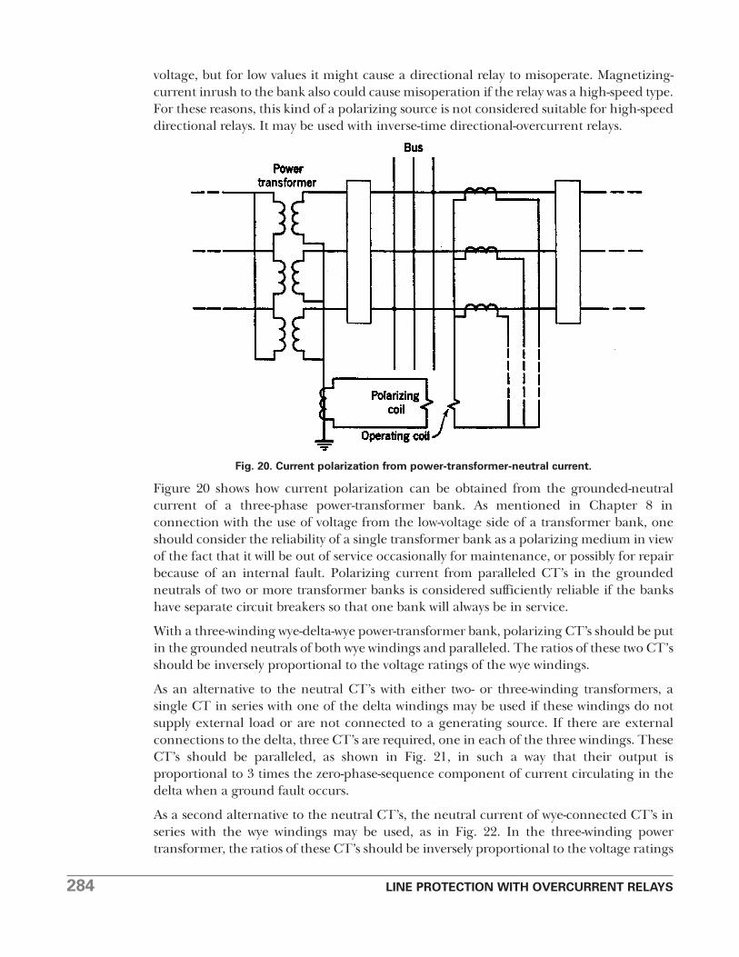
Figure 20 shows how current polarization can be obtained from the grounded-neutralcurrent of a three-phase power-transformer bank. As mentioned in Chapter 8 inconnection with the use of voltage from the low-voltage side of a transformer bank, oneshould consider the reliability of a single transformer bank as a polarizing medium in viewof the fact that it will be out of service occasionally for maintenance, or possibly for repairbecause of an internal fault. Polarizing current from paralleled CT’s in the groundedneutrals of two or more transformer banks is considered sufficiently reliable if the bankshave separate circuit breakers so that one bank will always be in service.
With a three-winding wye-delta-wye power-transformer bank, polarizing CT’s should be putin the grounded neutrals of both wye windings and paralleled. The ratios of these two CT’sshould be inversely proportional to the voltage ratings of the wye windings.
As an alternative to the neutral CT’s with either two- or three-winding transformers, asingle CT in series with one of the delta windings may be used if these windings do notsupply external load or are not connected to a generating source. If there are externalconnections to the delta, three CT’s are required, one in each of the three windings. TheseCT’s should be paralleled, as shown in Fig. 21, in such a way that their output isproportional to 3 times the zero-phase-sequence component of current circulating in thedelta when a ground fault occurs.
As a second alternative to the neutral CT’s, the neutral current of wye-connected CT’s inseries with the wye windings may be used, as in Fig. 22. In the three-winding powertransformer, the ratios of these CT’s should be inversely proportional to the voltage ratings
Fig. 20. Current polarization from power-transformer-neutral current.

LINE PROTECTION WITH OVERCURRENT RELAYS 285
of the wye windings, as when neutral CT’s are used. This alternative is not exactlyequivalent to neutral CT’s because of the possibility of false residual current, and,therefore, it should not be used with high-speed relays.
In an autotransformer bank with a delta tertiary, either of the two alternatives to theneutral CT’s may be employed. It is generally not permissible to use a CT in the neutralbecause the neutral current for a low-voltage fault may be reversed from the neutral currentfor a high-voltage fault. Infrequently, the distribution of fault currents is such that aneutral CT may be used; however, one should realize that the conditions might change assystem changes are made.
The primary-current rating of a neutral or delta-winding CT used for polarizing directionalunits of ground relays should be such that the polarizing and operating coils of a directionalunit get about the same current magnitudes for any fault for which it must operate.
Fig. 21. Current polarization from a loaded power-transformer delta.
Fig. 22. Alternative to Fig. 20.

286 LINE PROTECTION WITH OVERCURRENT RELAYS
This is more important for the so-called “directional-ground” relays whose publishedcharacteristics hold only if one current does not differ too much from the other.
In rare cases, such as that illustrated in Fig 23, none of the foregoing methods of currentpolarization may be used. Such circumstances may exist when one branch (N) of theequivalent circuit of a three-winding power transformer or autotransformer has negativereactance and when the zero-phase-sequence reactance of the system (M) connected tothis negative branch is less than the reactance of the negative branch. In other words, onthe side of this branch, the total zero-phase-sequence reactance including this branch ofthe transformer (M + N) is negative. Then, if this total negative reactance is smaller thanthe positive reactance of the branch representing the delta winding (P), all conditions aresatisfied to make unsuitable any of the current-polarizing methods that have beendescribed. When these circumstances exist, it becomes necessary either to use voltagepolarization or, possibly, a special combination of currents.20
Directional relays are available that are arranged for polarization simultaneously by voltageand current.18 Apart from simplifying the problem of stocking spare relays, “dualpolarization,” as it is called, has certain functional advantages. Sometimes, current orvoltage alone is unsatisfactory because either source may sometime be disconnected fromthe system and thereby be rendered useless when it is still needed. With dual polarization,either source may be disconnected so long as the other is left in service. In othercircumstances, either voltage or current polarization alone provides objectionably weakpolarization but the two together assure strong polarization.
NEGATIVE-PHASE-SEQUENCE DIRECTIONAL UNITSFOR GROUND-FAULT RELAYING�
When there is no zero-phase-sequence-current or voltage source for polarizing thedirectional unit of a ground relay, it is often possible to use a negative-phase-sequencedirectional unit if separate ground relaying is required. However, one must be sure thatsufficient negative-phase-sequence current and voltage will be available to assure reliableoperation of the directional unit for all conditions for which it must operate. In somesystems that are grounded through impedance, the negative-phase-sequence quantitiesmay be too small.
A negative-phase-sequence directional unit may be either a simple directional unitsupplied with negative-phase-sequence current and voltage from filter circuits21 or it mayconsist of two polyphase directional units with opposing torques, as described in Chap. 9.
Another advantage of negative-phase-sequence directional units is that they are notaffected by mutual induction between paralleled circuits when ground faults occur.
Fig. 23. Zero-phase-sequence diagram illustrating a case where polarization by the methods of Figs.20 to 22 will cause misoperation.

LINE PROTECTION WITH OVERCURRENT RELAYS 287
Chapter 15 shows that directional relays with zero-phase-sequence polarization mayoperate undesirably under such circumstances.
In spite of any advantages the negative-phase-sequence relay may have, it is used only as alast resort, because the zero-phase-sequence relay is simpler and easier to test, and becauseit produces more reliable torque under all conditions where it is applicable.
CURRENT-BALANCE AND POWER-BALANCE RELAYING
Prior to the introduction of high-speed distance and pilot relaying, current-balance andpower-balance relaying were used extensively for the protection of parallel lines. Asidefrom instantaneous overcurrent relaying, they were the only available forms ofinstantaneous. relaying for transmission lines. Their present-day usage for newinstallations is rare, but many old installations are still in service, and occasionally a newone is justified.
Current-balance relaying is illustrated in Fig. 24 for one phase of a pair of three-phaseparallel lines. Two overcurrent-type current-balance units are shown schematically, havingoperating coils O and restraining coils R. One unit has contacts A that trip breaker A, andthe other unit has contacts B for tripping breaker B. The trip circuits are not shown, butthey are arranged so that tripping of either breaker can occur only when both breakers areclosed. Furthermore, each phase-relay unit is restrained either by its control spring or byvoltage (not shown) so that it will not operate with operating-coil current correspondingto maximum load and no restraining current (or, in other words, it will not operate whenonly one line is closed and carrying maximum load). This restraint is necessary with thistype of relay to prevent immediate undesirable tripping when a line is being returned to
Fig. 24. Current balance relaying of parallel lines.
288 LINE PROTECTION WITH OVERCURRENT RELAYS
service and one end is closed while the other end is open. Such restraint is unnecessary ona current-balance ground relay obtaining current from the CT neutrals, because normallythere is no neutral current.
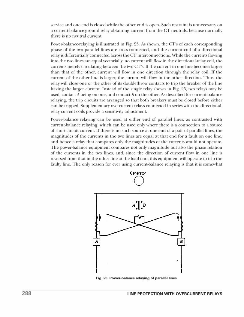
Power-balance-relaying is illustrated in Fig. 25. As shown, the CT’s of each correspondingphase of the two parallel lines are cross-connected, and the current coil of a directionalrelay is differentially connected across the CT interconnections. While the currents flowinginto the two lines are equal vectorially, no current will flow in the directional-relay coil, thecurrents merely circulating between the two CT’s. If the current in one line becomes largerthan that of the other, current will flow in one direction through the relay coil. If thecurrent of the other line is larger, the current will flow in the other direction. Thus, therelay will close one or the other of its doublethrow contacts to trip the breaker of the linehaving the larger current. Instead of the single relay shown in Fig. 25, two relays may beused, contact A being on one, and contact B on the other. As described for current-balancerelaying, the trip circuits are arranged so that both breakers must be closed before eithercan be tripped. Supplementary overcurrent relays connected in series with the directional-relay current coils provide a sensitivity adjustment.
Power-balance relaying can be used at either end of parallel lines, as contrasted withcurrent-balance relaying, which can be used only where there is a connection to a sourceof short-circuit current. If there is no such source at one end of a pair of parallel lines, themagnitudes of the currents in the two lines are equal at that end for a fault on one line,and hence a relay that compares only the magnitudes of the currents would not operate.The power-balance equipment compares not only magnitude but also the phase relationof the currents in the two lines, and, since the direction of current flow in one line isreversed from that in the other line at the load end, this equipment will operate to trip thefaulty line. The only reason for ever using current-balance relaying is that it is somewhat
Fig. 25. Power-balance relaying of parallel lines.

LINE PROTECTION WITH OVERCURRENT RELAYS 289
simpler and less expensive, especially if no voltage restraint is involved and sincesupplementary overcurrent relays are not required to establish the sensitivity.
Both current-balance and power-balance relaying are effective only while both lines are inservice. For single-line operation, supplementary relaying is required. This supplementaryrelaying is also required to provide back-up protection for faults in adjoining lines or othersystem elements, since the current- or power-balance relaying will not operate for faultsoutside the two parallel lines. Unless relaying comparable to that provided by distancerelays is used for single-line operation, faults during single-line operation will not becleared nearly so quickly as when both lines are in service; and, if fast clearing is requiredfor single-line operation, current-balance or power-balance relaying cannot be justified.The only exception to this is for protection against single-phase-to-ground faults for whichdistance relaying may not be economically feasible; then, current-balance or power-balance relaying will minimize the likelihood of a single-phase-to-ground fault on one linedeveloping into a fault involving the other line, when both lines are close together.
AUTOMATIC RECLOSING
Experience has shown that 70% to 95% of all high-voltage transmission-, subtransmission-,and distribution-line faults are non-persisting if the faulty circuit is quickly disconnectedfrom the system. This is because most line faults are caused by lightning, and, if theensuing arcing at the fault is not allowed to continue long enough to badly damageconductors or insulators, the line can be returned to service immediately.22 Where the faultpersists after the first trip and closure, experience has ah own it to be desirable to try asmany as two or three more reclosures before keeping the line out of service until thetrouble can be found and repaired.
Automatic reclosing is generally applied to all types of circuits. Subtransmission lineshaving overcurrent relaying usually have multi� equipment, with supplementary“synchronism-check” equipment at one end if it is likely that the line may sometime be theonly tie between certain generating stations. Synchronism-check equipment is relayequipment that permits a circuit breaker to be closed only if the parts to be connected bythe breaker are in synchronism. On radial lines, there is no need for synchronism check.
In distribution systems in which selectivity with branch-circuit fuses is involved,multireclosure is also used.23 Instantaneous and inverse-time overcurrent relays arearranged so that, when a fault occurs, the instantaneous relays operate to trip the breakerbefore a branch� fuse can blow, and the breaker is then immediately reclosed. However,after the first tripout, the instantaneous relays are automatically cut out of service so thatif the fault should persist the inverse-time relays would have to operate to trip the breaker.This gives time for the branch-circuit fuse of the faulty circuit to blow, if we assume thatthe fault is beyond this fuse. In this way, the cost of replacing blown branch-circuit fuses isminimized, and at the same time the branch-circuit outage is also minimized. If thebreaker is not tripped within a certain time after reclosure, the instantaneous relays areautomatically returned to service.
When industrial loads are to be fed from lines with automatic reclosing, certain problemsexist that must be solved before automatic reclosing can be safely permitted. They have to

290 LINE PROTECTION WITH OVERCURRENT RELAYS
do with the possible loss of synchronism between the utility and the industrial plant thatmakes it necessary to cut the plant loose from the utility before the utility’s breakers reclose.At the same time, the industrial plant may have to resort to some “load shedding” ofunessential loads so as to be able to supply its essential load from its own generating source.These problems, as well as other problems of industrial-plant protection, are discussed atlength and solutions are given in the material under Reference 24.
RESTORATION OF SERVICE TO DISTRIBUTION FEEDERSAFTER PROLONGED OUTAGES
Large economies can be effected in the design and operation of distribution circuits andrelated equipment by taking advantage of the diversity between loads. Under normaloperating conditions, the actual load on a distribution feeder will generally beconsiderably less than the total rating of the power-utilization equipment served by thefeeder. When such a feeder is quickly reclosed after the clearing of a fault, the inrushcurrent will not greatly exceed the normal load current, and the current will quickly returnto normal. But after such a feeder has been out of service long enough so that the normal“off” period of all loads, such as electric furnaces, refrigerators, water heaters, pumps, airconditioners, etc., has been exceeded, all these loads will be thrown on together with nodiversity between them. The total inrush current to all the electric motors involved, addedto the current of other loads, may be several times the normal peak-load current, decayingto approximately 1.5 times the normal peak-load current after several seconds.25 Thissubject has been called “cold-load restoration” or “cold-load pickup.”
Protective relaying for such feeders is faced with the problem of selecting between suchinrush currents and the current to a fault at or beyond the next automatic sectionalizingpoint. An induction-type extremely inverse-time-overcurrent relay, having a time-currentcurve closely matching that of a fuse down to an operating time of approximately 0.1second, has given some relief for such an application. However, the best solution seems tobe automatic sectionalizing on prolonged loss of voltage, and time-staggered automaticreclosing on the return of voltage.
COORDINATING WITH FUSES
When overcurrent relays must be selective with fuses, the relay that will provide suchselectivity and still be the fastest for faults for which it must operate is the extremely inversetype just described for cold-load restoration. Occasionally it may be necessary to add adelay of a few cycles, in the form of an auxiliary relay, to maintain selectivity at very highfault currents.
A-C AND CAPACITOR TRIPPING
Some installations, particularly in distribution systems, cannot justify the expense and themaintenance of a storage battery and its charging equipment solely for use with protective-relaying equipment of one or two circuits. Then “a-c tripping” or “capacitor tripping” maybe used if they are applicable.
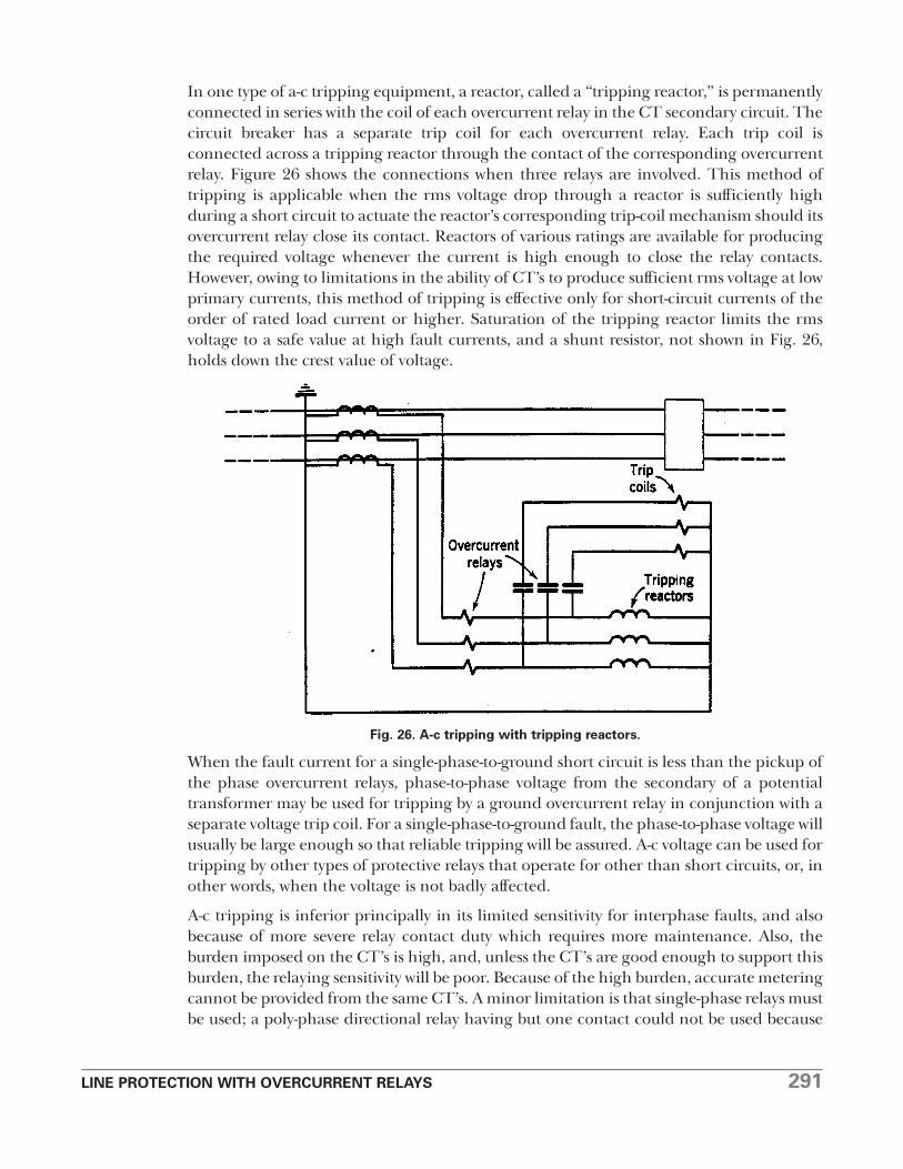
LINE PROTECTION WITH OVERCURRENT RELAYS 291
In one type of a-c tripping equipment, a reactor, called a “tripping reactor,” is permanentlyconnected in series with the coil of each overcurrent relay in the CT secondary circuit. Thecircuit breaker has a separate trip coil for each overcurrent relay. Each trip coil isconnected across a tripping reactor through the contact of the corresponding overcurrentrelay. Figure 26 shows the connections when three relays are involved. This method oftripping is applicable when the rms voltage drop through a reactor is sufficiently highduring a short circuit to actuate the reactor’s corresponding trip-coil mechanism should itsovercurrent relay close its contact. Reactors of various ratings are available for producingthe required voltage whenever the current is high enough to close the relay contacts.However, owing to limitations in the ability of CT’s to produce sufficient rms voltage at lowprimary currents, this method of tripping is effective only for short-circuit currents of theorder of rated load current or higher. Saturation of the tripping reactor limits the rmsvoltage to a safe value at high fault currents, and a shunt resistor, not shown in Fig. 26,holds down the crest value of voltage.
When the fault current for a single-phase-to-ground short circuit is less than the pickup ofthe phase overcurrent relays, phase-to-phase voltage from the secondary of a potentialtransformer may be used for tripping by a ground overcurrent relay in conjunction with aseparate voltage trip coil. For a single-phase-to-ground fault, the phase-to-phase voltage willusually be large enough so that reliable tripping will be assured. A-c voltage can be used fortripping by other types of protective relays that operate for other than short circuits, or, inother words, when the voltage is not badly affected.
A-c tripping is inferior principally in its limited sensitivity for interphase faults, and alsobecause of more severe relay contact duty which requires more maintenance. Also, theburden imposed on the CT’s is high, and, unless the CT’s are good enough to support thisburden, the relaying sensitivity will be poor. Because of the high burden, accurate meteringcannot be provided from the same CT’s. A minor limitation is that single-phase relays mustbe used; a poly-phase directional relay having but one contact could not be used because
Fig. 26. A-c tripping with tripping reactors.

292 LINE PROTECTION WITH OVERCURRENT RELAYS
there would not be a suitable source for operating an auxiliary relay to provide thenecessary additional contacts.
Capacitor tripping uses the stored energy of a charged capacitor to actuate a trip-coilmechanism. The capacitor is charged through a rectifier from a-c voltage obtained fromthe system. Its principal advantage over a-c tripping is greater sensitivity for interphasefaults. Also, it permits the use of polyphase relays that do not need auxiliary relays,although an additional capacitor tripping device has been used to operate an auxiliarytripping relay. Its principal disadvantage is that the circuit-breaker trip mechanism getsonly one impulse and not a steady force as with a-c tripping; this fact makes some peoplefeel that the breaker requires a more “hair-triggered” trip mechanism, and consequentlythat it is apt to be less reliable.
PROBLEM
Given a simple loop system as shown in Fig. 27, where the impedances are in percent basedon the rating of one of the generators.. Adjust overcurrent relays having timecharacteristics of Chapter 3, Fig. 3, for the protection of all the lines against phase faults,assuming and indicating directional elements, wherever necessary, by an arrow pointing inthe tripping direction. Neglect the fact that the pickup should be well above load current.Make your adjustment on the basis of per unit primary current, assuming that any desiredpickup can be obtained.
Fig. 27. Illustration for problem.

LINE PROTECTION WITH OVERCURRENT RELAYS 293
BIBLIOGRAPHY
1. “Long 60-Cycle Arcs in Air,” by A. P. Strom, AIEE Trans., 65 (1946), pp. 113-117.Discussions, pp. 504-507.
2. “Power System Faults to Ground, Part II Fault Resistance,” by C. L. Gilkeson, P. A.Jeanne, and E. F. Vaage, A1EE Trans., 56 (1937), pp. 428-433, 474.
3. “Application of the Ohm and Mho Principles to Protective Relays,” by A. R. van C.Warrington, AIEE Trans., 65 (1946), pp. 378-386. Discussions, pp. 490-491.
“Reactance Relays Negligibly Affected by,Arc Impedance,” by A. R. van C. Warrington, Elec.World, 98, No. 12 (Sept. 19, 1931), pp. 502-505.
4. “Sensitive Ground Protection for Radial Distribution Feeders,” by Lloyd F. Hunt and J.H. Vivian, AIEE Trans., 59 (1940), pp. 84-87. Discussions, pp. 87-90.
“Some Recent Relay Developments,” by Lloyd F. Hunt and A. A. Kroneberg, AIEE Trans.,53 (1934), pp. 530-535.
5. “Effect of Fault Resistance on Ground-Fault Current,” by Martin J. Lantz, AIEE Trans.,72, Part III (1953), pp. 1016-1019.
6. “Instantaneous Overcurrent Relays for Distance Relaying,” by C. B. Frier, AIEE Trans., 54(1935), pp. 404-407. Discussions, pp. 883-884.
7. Silent Sentinels, Westinghouse Electric Corp., Meter Division, Newark, N. J.
8. “A Study of Directional Element Connections for Phase Relays,” by W. K. Sonnemann,AIEE Trans., 69, Part II (1950), pp. 1438-1450. Discussions, pp. 1450-1451.
9. “Ground Fault Relay Protection of Transmission Lines,” by J. L. Blackburn, AIEE Trans.,71 (1952), pp. 685-691. Discussions, pp. 691-692.
10. “Ground Relays Set for Simultaneous 1-Ph Faults,” by John M. Showman, Elec. World,Sept. 6, 1954, p. 102.
11. “Earth-Leakage Relays; with Use of Ring-Type Current Transformers,” by E. T. B.Gross, Electrician (London), 123 (July, 1939), pp. 93-95.
“Sensitive Ground Protection,” AIEE Committee, AIEE Trans., 69, Part I (1950), pp. 473-475. Discussions, pp. 475-476.
12. “Some Utility Ground-Relay Problems,” by H. C. Barnes, and A. J. McConnell, AIEETrans., 74, Part III (1055), pp. 417-428. Discussions, pp. 428-433.
13. “A New Single-Phase-to-Ground Fault-Detecting Relay,” by W. K. Sonnemann, AIEETrans., 61 (1942), pp. 677-680. Discussions, pp. 995-996.
14. “Criteria for Neutral Stability of Wye-Grounded-Primary Broken-Delta SecondaryTransformer Circuits,” by H. S. Shott and H. A. Peterson, AIEE Trans., 60 (1941), pp. 997-1002. Discussions, pp. 1394-1395.
15. “Neutral Inversion of a Single Potential Transformer Connected Line-to-Ground on anIsolated Delta System,” by Lyle L. Gleason, AIEE Trans., 70, Part I, pp. 103 110. Discussions,pp. 110-111.

294 LINE PROTECTION WITH OVERCURRENT RELAYS
16. “Sensitive Ground Protection for Transmission Lines and Distribution Feeders,” E. T.B. Gross, AIEE Trans., 60 (1941), pp. 968-971.
17. Circuit Analysis of A-C Power Systems, Vol. I, by Edith Clarke, John Wiley & Sons, New York,1943.
18. “Dual-Polarized Directional-Ground Relays,” by W. C. Morris, Distribution, April, 1952,pp. 8, 9.
19. United States Patent 2378800.
20. “Ground Relay Polarization,” by J. L. Blackburn, AIEE Trans., 71 (1952), pp. 1088-1093.Discussions, pp. 1093-1095.
21. “Directional Overcurrent Ground Relaying,” by B. V. Hoard and S. C. Leyland, Elec. J.,36, No. 3, March, 1939, pp. 97-101.
22. “Faster Reclosing Breakers Needed,” by J. T. Logan, Elec. World, 103, No. 16 (April 21,1934), pp. 571-573.
23. “”Progress Report on Coordination of Construction and Protection of DistributionCircuits Based on Operating Data for Year 1949,” by AIEE Committee, Technical Paper52-13.
“Reclosure Sequence and Coordination,” by R. C. Kirk, Elec. Light and Power, Dec., 1954, pp.99-100, 148.
24. “Relay Protection of 33-Kv Tie Feeders to a Large Industrial Customer,” by W. H.O’Connor and H. D. Ruger, Elec. Eng., Feb., 1952, p. 165.
“Protective Relaying on Industrial Power Systems,” by Carl M. Lathrop, and Charles E.Schleckser, AIEE Trans., 70, Part II, pp. 1341-1344. Discussions, pp. 1344-1345.
“Protection for an Industrial Plant Connected to a Utility System with Reclosing Breakers,”by D. F. Langenwalter, Distribution, 15, No. 5 (Nov., 1953), pp. 17-20.
“Parallel Operation of Industrial Power Plants with Public Utilities,” by L. G. Levoy,Distribution, 15, No. 5 (Nov., 1953), pp. 10-16.
“Frequency Relays Disconnect Synchronous Motors,” by A. J. Meyers, Power Generation, July,1949, p. 82.
“Application and Tests of Frequency Relays for Load Shedding,” by L. L. Fountain and J. L. Blackburn, AIEE Trans., 73, Part III (1954), pp. 1660-1664. Discussions, pp. 1664-1668.
“Selecting A-C Overcurrent Protective Device Settings for Industrial Plants,” by F. P.Brightman, AIEE Trans., 71, Part II (1952), pp. 203-211.
“More about Setting Industrial Relays,” by F. P. Brightman, AIEE Trans., 73 (1954), pp. 397-405. Discussions, pp. 405-406.
“Inertia Relay ‘Anticipates’ to Facilitate Reclosure,” by J. T. Logan and J. H. Miles, Elec.World, 113 (April, 1940), pp. 1061-1064.
Industrial Power Systems Handbook, McGraw-Hill Book Co., New York, 1955.
25. “A New Approach to Cold Load Restoration,” by Oliver Ramsaur, Elec. World, Oct. 6,1952, pp. 101-103.
LINE PROTECTION WITH OVERCURRENT RELAYS 295
“New Relay Assures Feeder Resumption after Outage,” by M. H. Pratt, L. J. Audlin, andA. J. McConnell, Elec. World, Part I, Sept. 10, 1949, pp. 99-103. Part II, Sept. 24, 1949,pp. 95-98.
“Diversity a New Problem in Feeder Pickup,” by C. E. Hartay and C. J. Couy, Elec. Light andPower, Oct., 1952, pp. 142-146.