Embed Size (px)
Citation preview

Chapter 13Bridge Design Manual - 2002 Approximate Methods of Analysis
Ethiopian Roads Authority Page 13-1
13 APPROXIMATE METHODS OF ANALYSIS
13.1 GENERAL
This chapter describes methods of analysis suitable for the design and evaluation of bridgesand is limited to the modeling of structures and the determination of force effects.
Other methods of analysis that are based on documented material characteristics and thatsatisfy equilibrium and compatibility (see Chapter 3: Load Requirements, section 3.10: LoadFatigue) may also be used.
In general, bridge structrures are to be analyzed elastically. However, this chapter permits theinelastic analysis or redistribution of force effects in some continuous beam superstructures.It specifies inelastic analysis for compressive members behaving ineleastically and as analternative for extreme event limit states.
If the span length of a superstructure with torsionally stiff closed cross-sections exceeds 2.5times its width, the superstructure shall be idealized as a single steel spine within a concretebeam.
Segments of horizontally curved superstructures with torsionally stiff closed sections whosecentral angle subtended by a curved span or portion thereof is less than 12° shall be analyzedas if the segment were straight.
13.2 NOTATIONS
The following notation shall apply to this chapter:A = Area of concrete (mm2)A = area of cross-section (mm2)Ac = area of concrete on the flexural tension side of the member as shown in Figure 13-5
(mm2)Ao = area enclosed by centerlines of elements (mm2)Aps = area of prestressing steel on the flexural tension side of the member, shown in Figure
13-5, reduced for any lack of full development at the section under investigation(mm2)
As = area of non-prestressed reinforcing steel on flexural tension side of member, asshown in Figure 13-5, reduced for any lack of full development at the section underinvestigation (mm2)
b = width of plate element (mm)bv = effective web width taken as the minimum web width within depth dv (mm)C = continuity factor, 1.0 for simply supported and 0.8 for continuous spansdv = effective shear depth (mm)D = stiffness ratio: Dx/Dy
Dx = flexural rigidity in direction of main bars (N-mm2/mm)Dy = flexural rigidity perpendicular to the main bars (N-mm2/mm)E = equivalent width (mm)

Chapter 13Approximate Methods of Analysis Bridge Design Manual - 2002
Page 13-2 Ethiopian Roads Authority
EB = modulus of elasticity of beam material (MPa)ED = modulus of elasticity of deck material (MPa)e = eccentricity of a design truck or a design lane load from the center of gravity of the
pattern of girders (mm)eg = distance between the centers of gravity of the basic beam and deck (mm)fpe = effective stress after losses (MPa)fpo = stress in prestressing steel when the stress in the surrounding concrete is 0.0 (MPa)h = depth of deck (mm)I = moment of inertia of beam (mm4)Ip = polar moment of inertia (mm4)Is = moment of inertia of the equivalent strip (mm4)J = St. Venant's torsional inertia (mm4)K = effective length factorKg = longitudinal stiffness parameterKs = strip stiffnesslt = tire length along direction of traffic (mm)L = span of beam (mm)L1 = modified span length taken ≤ of the actual span or 18,000 (mm)+M = positive moment (Nmm/mm)-M = negative moment (Nmm/mm)Mu = factored moment (Nmm)Nb = number of beams, stringers or girdersNL = number of design lanesNu = factored axial force taken as positive if tensile (N)p = tire pressure taken as 0.86 MPaR = reaction on exterior beam in terms of laness = length of a side element (mm)sx = crack spacing parameterS = spacing of supporting components (mm)S = span length (mm)t = thickness of plate-like element (mm)ts = deck slab thickness (mm)V = shear stress on concreteVu = factored shear force (N)W = physical edge-to-edge width of bridge (mm)W1 = modified edge-to-edge width of bridge taken to be ≤ of the actual width or 18,000
mm for multilane loading, or 9,000 mm for single-lane loading (mm)X = distance from load to point of support (mm)x = horizontal distance from the center of gravity of the pattern of girders to each girder
(mm)Xext = horizontal distance from the center of gravity of the pattern of girders to the exterior
girder (mm)εx = strain in reinforcementθ = skew angle (DEG)ϕ = resistance factor for shear specified in Table 9-7.

Chapter 13Bridge Design Manual - 2002 Approximate Methods of Analysis
Ethiopian Roads Authority Page 13-3
13.3 DECKS
13.3.1 GENERAL
An approximate method of analysis in which the deck is subdivided into strips perpendicularto the supporting components shall be considered acceptable for decks other than fully filledand partially filled grids, for which the provisions of section Live Load Distribution on Fullyand Partially Filled Grids, below, shall apply.
Where the strip method is used, the extreme positive moment in any deck panel betweengirders shall be taken to apply to all positive moment regions. Similarly, the extremenegative moment over any beam or girder shall be taken to apply to all negative momentregions.
In determining the strip widths, the effects of flexure in the secondary direction and oftorsion on the distribution of internal force effects are accounted for to obtain flexural forceeffects approximating those that would be provided by a more refined method of analysis.
Depending on the type of deck, modeling and design in the secondary direction may utilizeone of the following approximations:
• Secondary strip designed in a manner like the primary strip, with all the limit statesapplicable;
• Resistance requirements in the secondary direction determined as a percent of that in theprimary one as specified in the traditional approach for reinforced concrete slabs (as inRef. 1); or
• Minimum structural and/or geometry requirements specified for the secondary directionindependent of actual force effects, as is the case for most wood decks.
The approximate strip model for decks is based on rectangular layouts. While skew generallytends to decrease extreme force effects, it produces negative moments at corners, torsionalmoments in the end zones, substantial redistribution of reaction forces, and a number ofother structural phenomena that should be considered in the design.
13.3.2 APPLICABILITY
The use of design aids such as computer software for decks containing prefabricatedelements shall be permitted in lieu of analysis if the performance of the deck is documentedand supported by sufficient technical evidence. The Designer shall be responsible for theaccuracy and implementation of any design aids used.
For slab bridges and concrete slabs spanning more than 4.6 m and with span primarily in thedirection parallel to traffic, the provisions of section 13.5: Equivalent Strip Widths for Slab-Type Bridges, shall apply.

Chapter 13Approximate Methods of Analysis Bridge Design Manual - 2002
Page 13-4 Ethiopian Roads Authority
13.3.3 WIDTH OF EQUIVALENT INTERIOR STRIPS
The Width of the equivalent strip of a deck shall be taken as specified in Table 13-1.Where decks span primarily in the direction parallel to traffic, strips supporting an axle loadshall not be taken to be greater than 1.0 m for open grids, and not greater than 3.0 m for allother decks where multilane loading is being investigated. For deck overhangs, whereapplicable, the provisions of section 3.8: Gravity Loads/Deck Overhang Load shall be usedin lieu of the strip width specified in Table 13-1 for deck overhangs. The equivalent strips fordecks that span primarily in the transverse direction shall not be subject to width limits.
Values provided for equivalent strip widths and strength requirements in the secondarydirection are based on past experience. Practical experience and future research work maylead to refinement.
To get the load per unit width of the equivalent strip, divide the total load on one designtraffic lane by the calculated strip width.
TYPE OF DECKDIRECTION OF PRIMARY
STRIP RELATIVE TOTRAFFIC
WIDTH OF PRIMARYSTRIP (mm)
Concrete:• Cast-in-place
• Cast-in-place with stay-in-place concrete formwork
Overhang
Either Parallel or Perpendicular
Either Parallel or Perpendicular
1140 + 0.833X
+M: 660 + 0.55S-M: 1220 + 0.25S
+M: 660 + 0.55S-M: 1220 + 0.25S
Wood:• Spike-laminated- Continuous decks or
interconnected panels
- Non-interconnectedpanels
• Planks
ParallelPerpendicular
ParallelPerpendicular
2.0h + 7604.0h + 1020
2.0h + 7602.0h +1020
Plank WidthS = spacing of supporting components (mm)h = depth of deck (mm)+M = positive moment-M = negative momentX = distance from load to point of support (mm)
Table 13-1 Equivalent Strips for Different Types of Decks

Chapter 13Bridge Design Manual - 2002 Approximate Methods of Analysis
Ethiopian Roads Authority Page 13-5
13.3.4 WIDTH OF EQUIVALENT STRIPS AT EDGES OF SLABS
For the purpose of design, the notional edge beam shall be taken as a reduced deck stripwidth specified herein, plus any additional integral local thickening or similar protrudenceacting as a stiffener to the deck. Edge beams shall be assumed to support one line of wheelsand, where appropriate, a tributary portion of the design lane load.
Longitudinal Edges: Where decks span primarily in the direction of traffic, the effectivewidth of a strip, with or without an edge beam, shall be taken as the sum of the distancebetween the edge of the deck and the inside face of the barrier, plus 300 mm, plus one-half ofthe strip width, specified in either section “Width of Equivalent Interior Strips” above, orsection 13.5: Equivalent Strip Widths for Slab-Type Bridges, as appropriate. The effectivewidth shall not exceed either the full strip width or 1800 mm.
Transverse Edges: The effective width of a strip, with or without an edge beam, shall betaken as the sum of the distance between the transverse edge of the deck and the centerline ofthe first line of support for the deck, usually taken as a girder web, plus one-half of the widthof strip as specified in section 13.5: Equivalent Strip Widths for Slab-Type Bridges. Theeffective width shall not exceed the full strip width specified in section 13.5: EquivalentStrip Widths for Slab-Type Bridges.
13.3.5 DISTRIBUTION OF WHEEL LOADS
If the spacing of supporting components in the secondary direction exceeds 1.5 times thespacing in the primary direction, all of the wheel loads shall be considered to be applied tothe primary strip, and the provisions specified in the traditional approach shall be appliedto the secondary direction.
If the spacing of supporting components in the secondary direction is less than 1.5 times thespacing in the primary direction, the deck shall be modeled as a system of intersecting strips.
The width of the equivalent strips in both directions shall be taken as specified in Table 13-1.Each wheel load shall be distributed between two intersecting strips. The distribution shallbe determined as the ratio between the stiffness of the strip and the sum of stiffnesses of theintersecting strips. In the absence of more precise calculations, the strip stiffness, ks, shall beestimated as:
(13.1)
where: Is = moment of inertia of the equivalent strip (mm4)S = spacing of supporting components (mm)
13.3.6 CALCULATION OF FORCE EFFECTS
The strips shall be treated as continuous beams or simply supported beams, as appropriate.
3
ss
S
I*Ek =

Chapter 13Approximate Methods of Analysis Bridge Design Manual - 2002
Page 13-6 Ethiopian Roads Authority
Span length shall be taken as the center-to-center distance between the supportingcomponents. For the purpose of determining force effects in the strip, the supportingcomponents shall be assumed to be infinitely rigid.
The wheel loads shall be modeled as concentrated loads or as patch loads whose length alongthe span shall be the length of the tire contact area, as specified in section 3.8 Gravity Loads:Tire Contact Area, plus the depth of the deck. The strips should be analyzed by classicalbeam theory.
The design section for negative moments and shear forces, where investigated, shall be takenas follows:• For monolithic construction and concrete box beams at the face of the supporting
component;• For steel and wood beams: one-quarter the flange width from the centerline of support;• For precast I-shaped and T-shaped concrete beams: one-third the flange width, but not
exceeding 380 mm from the centerline of support.
For the purpose of this chapter, each web of a steel or concrete box beam shall be treated as aseparate supporting component.
For short-spans, the force effects calculated using the footprint could be significantly lower,and more realistic, than force effects calculated using concentrated loads.
Past practice has been not to check shear in typical decks. A design section for shear isprovided for use in nontraditional situations. It is not the intent to investigate shear in everydeck.
13.3.7 CROSS-SECTIONAL FRAME ACTION
Where decks are an integral part of Box or Cellular cross-sections, flexural and/or torsionalstiffnesses of supporting components of the cross-section, i.e., the webs and bottom flange,are likely to cause significant force effects in the deck. Those components shall be includedin the analysis of the deck.
If the length of a frame segment is modeled as the width of an equivalent strip, provisions ofabove sections Width of Equivalent Interior Strips, Distribution of Wheel Loads, andCalculation of Force Effects, shall be used.
The model used is essentially a transverse segmental strip, in which flexural continuityprovided by the webs and bottom flange is included. Such modeling is restricted to closedcross-sections only. In open-framed structures, a degree of transverse frame action alsoexists, but it can be determined only by complex, refined analysis.
In normal beam-slab superstructures, cross-sectional frame action may safely be neglected.If the slab is supported by box beams or is integrated into a cellular cross-section, the effects

Chapter 13Bridge Design Manual - 2002 Approximate Methods of Analysis
Ethiopian Roads Authority Page 13-7
of frame action could be considerable. Such action usually decreases positive moments, butmay increase negative moments resulting in cracking of the deck. For larger structures, athree-dimensional analysis shall be appropriate. For smaller structures, the analysis could berestricted to a segment of the bridge whose length is the width of an equivalent strip.
Extreme force effects shall be calculated by combining the:• Longitudinal response of the superstructure approximated by classical beam theory,
and• Transverse flexural response modeled as a cross-sectional frame.
13.3.8 LIVE LOAD DISTRIBUTION ON FULLY FILLED AND PARTIALLY FILLED GRIDS
Moments in Nmm/mm of grid due to live load in filled and partially filled grids shall bedetermined as:• Main bars transverse to traffic:
M = C lt p D0.25 [42.3 * ln(0.039S) - 74] (13.2)
• Main bars parallel to direction of traffic
(13.3)
where: S = span length (mm), 500 mm < S < 10 000 mm in Equation 13.2, and500 mm < S < 5000 mm in Equation 13.3
C = continuity factor, 1.0 for simply supported and 0.8 for continuous spanslt = tire length, along direction of traffic, as specified in section 3.8 Gravity
Loads: Tire Contact Area (mm)p = tire pressure taken as 0.86 MPaD = Dx/Dy
Dx = flexural rigidity in direction of main bars (N-mm2/mm)Dy = flexural rigidity perpendicular to the main bars (N-mm2/mm)
Where test results are not available, the stiffness ratio, D, shall be taken as:• For fully filled grids with at least 38mm monolithic overfill ........................................2.0• For all other fully filled grids.........................................................................................2.5• For partially filled grids with at least 38 mm monolithic overfill .................................8.0• For all other partially filled grids .................................................................................10.0
The moment equations have been derived from orthotropic plate theory and stiffness ratiosobtained in full-scale laboratory tests of filled and partially filled grids based on a 500 mmwide, 200 mm long tire contact area. Moments resulting from these equations compare wellwith full-scale test results and finite difference and finite element solutions. The tire contactarea, specified in section 3.8 Gravity Loads: Tire Contact Area, factored for the Strength ILoad Combination, is a 510 mm by 385 mm rectangle, therefore Equations 13.2 and 13.3 areexpected to produce conservative results.
200
l]D10200)S039.0ln(D8060[CpM
t46.029.0 −=

Chapter 13Approximate Methods of Analysis Bridge Design Manual - 2002
Page 13-8 Ethiopian Roads Authority
For on-the-road tire loads greater than those indicated by the design truck, the factored tirepressure should not be taken to be greater than 0.86 MPa, unless supported by condition-specific data, which includes the tire contact area.
13.3.9 INELASTIC ANALYSIS
The inelastic finite element analysis or yield line analysis shall not be used unless otherwisepermitted by ERA.
13.4 BEAM-SLAB BRIDGES
13.4.1 APPLICATION
For beam spacing exceeding the range of applicability as specified in Tables 13-3 through13-9, the live load on each beam shall be the reaction of the loaded lanes based on the leverrule unless specified otherwise herein.
The lever rule involves summing moments about one support to find the reaction at anothersupport by assuming that the supported component is hinged at interior supports.
When using the lever rule on a three-girder bridge, the notional model should be taken asshown in Figure 13-1. Moments should be taken about the assumed, or notional, hinge in thedeck over the middle girder to find the reaction on the exterior girder.
Figure 13-1 Notional Model for Applying Lever Rule to Three-Girder Bridges
The provisions of section 3.8: Gravity Load: Multiple Presence of Live Load specify thatmultiple presence factors shall not be used with the approximate load assignment methodsother than statical moment or lever arm methods because these factors are alreadyincorporated in the distribution factors.
Bridges not meeting the requirements of this chapter shall be analyzed as specified inChapter 12: Detail Design of Bridges and Structures.
The distribution of live load, specified in the two following sections of this subchapter, shallbe used for girders, beams, and stringers, other than multiple steel box beams with concretedecks that meet the following conditions and any other conditions identified in tables ofdistribution factors as specified herein:

Chapter 13Bridge Design Manual - 2002 Approximate Methods of Analysis
Ethiopian Roads Authority Page 13-9
• Width of deck is constant;• Number of beams is not less than four, unless otherwise specified;• Beams are parallel and have approximately the same stiffness;• Unless otherwise specified, the roadway part of the overhang, de, does not exceed 0.9m;• Curvature in plan is less than the limit specified in section 13.1: General above; and• Cross-section is consistent with one of the cross-sections shown in Table 13-2.
Where moderate deviations from a constant deck width or parallel beams exist, the equationsin the tables of distribution factors shall be used in conjunction with a suitable value forbeam spacing.
In Strength Load Combination II, applying a distribution factor procedure to a loadinginvolving a heavy permit load can be overly conservative unless lane-by-lane distributionfactors are available. Use of a refined method of analysis will circumvent this situation.
Additional requirements for multiple steel box girders with concrete decks shall be asspecified in section “Interior Beams with Concrete Decks,” below.
Where bridges meet the conditions specified herein, permanent loads of and on the deckshall be distributed uniformly among the beams and/or stringers.
Live load distribution factors, specified herein, shall be used for permit and rating vehicleswhose overall width is comparable to the width of the design truck.
Unless otherwise stated, the stiffness parameters for area, moments of inertia and torsionalstiffness used herein and indicated in the following text shall be taken as those of the cross-section to which traffic will be applied, i.e., usually the composite section.
The longitudinal stiffness parameter, Kg, shall be taken as:
Kg =n (I + A eg2) in which: n = EB / ED (13.4)
where: EB =modulus of elasticity of beam material (MPa)ED = modulus of elasticity of deck material (MPa)I = moment of inertia of beam (mm4)eg = distance between the centers of gravity of the basic beam and deck (mm)A = Area of concrete (mm2)
The parameters A and I in Equation 13.4 shall be taken as those of the non-composite beam.
The bridge types indicated in Tables 13-3 through 13-9, with reference to Figure 13-1, shallbe taken as representative of the type of bridge to which each approximate equation applies.
Except as permitted by Chapter 2: General Requirements, regardless of the method ofanalysis used, i.e., approximate or refined, exterior girders of multi-beam bridges shall nothave less resistance than an interior beam.
Chapter 13Approximate Methods of Analysis Bridge Design Manual - 2002
Page 13-10 Ethiopian Roads Authority
Most of the equations for distribution factors were derived for constant deck width andparallel beams. Past designs with moderate exceptions to these two assumptions haveperformed well when the "S/D" distribution factors were used. While the distribution factorsspecified herein are more representative of actual bridge behavior, common sense indicatesthat some exceptions are still possible, especially if the parameter "S" is chosen with prudentjudgment.
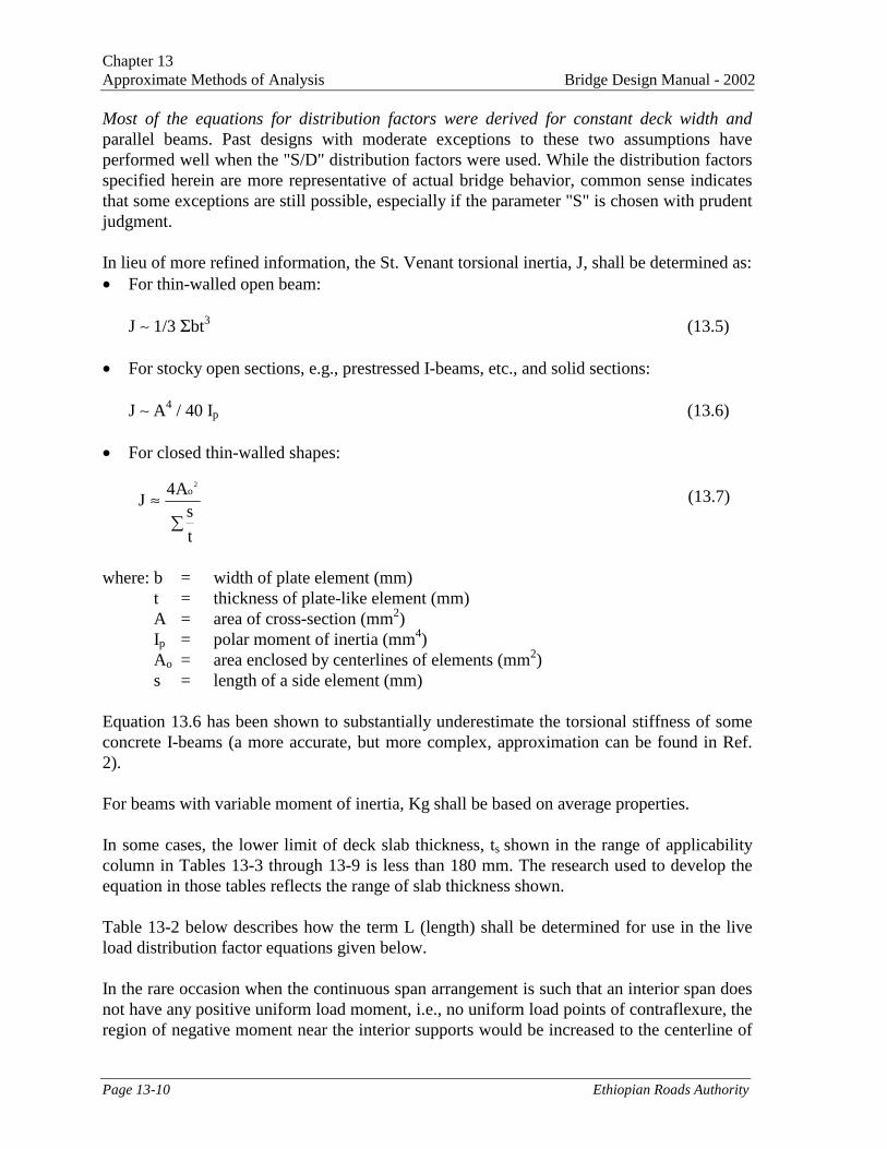
In lieu of more refined information, the St. Venant torsional inertia, J, shall be determined as:• For thin-walled open beam:
J ∼ 1/3 Σbt3 (13.5)
• For stocky open sections, e.g., prestressed I-beams, etc., and solid sections:
J ∼ A4 / 40 Ip (13.6)
• For closed thin-walled shapes:
where: b = width of plate element (mm)t = thickness of plate-like element (mm)A = area of cross-section (mm2)Ip = polar moment of inertia (mm4)Ao = area enclosed by centerlines of elements (mm2)s = length of a side element (mm)
Equation 13.6 has been shown to substantially underestimate the torsional stiffness of someconcrete I-beams (a more accurate, but more complex, approximation can be found in Ref.2).
For beams with variable moment of inertia, Kg shall be based on average properties.
In some cases, the lower limit of deck slab thickness, ts shown in the range of applicabilitycolumn in Tables 13-3 through 13-9 is less than 180 mm. The research used to develop theequation in those tables reflects the range of slab thickness shown.
Table 13-2 below describes how the term L (length) shall be determined for use in the liveload distribution factor equations given below.
In the rare occasion when the continuous span arrangement is such that an interior span doesnot have any positive uniform load moment, i.e., no uniform load points of contraflexure, theregion of negative moment near the interior supports would be increased to the centerline of
�
≈
t
sA4
J2
o (13.7)

Chapter 13Bridge Design Manual - 2002 Approximate Methods of Analysis
Ethiopian Roads Authority Page 13-11
the span, and the L used in determining the live load distribution factors would be theaverage of the two adjacent spans.
Force Effect L (mm)
Positive Moment The length of the span for whichmoment is being calculated
Negative Moment – Near interior supportsof continuous spans from point ofcontraflexure to point of contraflexure undera uniform load on all spans
The average length of the twoadjacent spans
Negative Moment – Other than near interiorsupports of continuous spans
The length of the span for whichmoment is being calculated
Shear The length of the span for whichshear is being calculated
Exterior Reaction The length of the exterior span
Interior Reaction of Continuous Span The average length of the twoadjacent spans
Table 13-2 “L” for Use in Live Load Distribution Factor Equations
13.4.2 INTERIOR BEAMS WITH CONCRETE DECKS
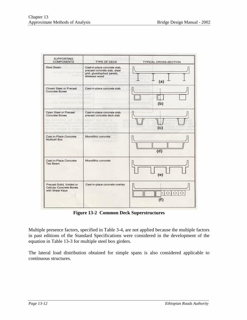
The live load flexural moment for interior beams with concrete decks shall be determined byapplying the lane fraction specified in Table 13-3. Applicable cross-sections are depicted inFigure 13-2.
For preliminary design, the terms Kg/(L ts3) and I/J shall be taken as 1.0.
For concrete beams, other than box beams, used in multi-beam decks with shear keys:• Deep, rigid end diaphragms shall be provided to ensure proper load distribution, and• If the stem spacing of stemmed beams is less than 1.2 m or more than 3.0 m, a refined
analysis shall be used.
For multiple steel box girders with a concrete deck, the live load flexural moment shall bedetermined using the distribution factor specified in Table 13-3.
When the spacing of the box girders varies along the length of the bridge, the value of NL
shall be determined, as specified in section 3.8: Gravity Loads/Number of Lanes, using thewidth, W, taken at midspan.
The results of analytical and model studies of simple span multiple box section bridges (Ref.3) showed that folded plate theory could be used to analyze the behavior of bridges of thistype.
Chapter 13Approximate Methods of Analysis Bridge Design Manual - 2002
Page 13-12 Ethiopian Roads Authority
Figure 13-2 Common Deck Superstructures
Multiple presence factors, specified in Table 3-4, are not applied because the multiple factorsin past editions of the Standard Specifications were considered in the development of theequation in Table 13-3 for multiple steel box girders.
The lateral load distribution obtained for simple spans is also considered applicable tocontinuous structures.

Chapter 13Bridge Design Manual - 2002 Approximate Methods of Analysis
Ethiopian Roads Authority Page 13-13
Type of Beams ApplicableCross-sectionfrom Figure
13-2
Distribution Factors Range ofApplicability
Concrete Deck onWood Beams
l One Design Lane Loaded: S/3700Two or More Design Lanes Loaded:S/3000
S ≤ 1800
One Design Lane Loaded:
0.06 + S 0.4 S 0.3 Kg0.1
4300 L Lts3
Two or More Design Lanes Loaded:
0.075 + S 0.6 S 0.2 Kg0.1
4300 L Lts3
1100≤ S≤4900110 ≤ ts ≤ 3006000≤L≤73000Nb ≥ 4
Concrete Deck, FilledGrid, or PartiallyFilled Grid on Steel orConcrete Beams;Concrete T-Beams,T-and Double T-Sections
a, e, k and alsoi, j if
sufficientlyconnected toact as a unit
Use lesser of the values obtained fromthe equation above with Nb = 3 or thelever rule
Nb = 3
Multicell ConcreteBox Beam
d One Design Lane Loaded:
1.75 + S 300 0.35 1 0.45
1100 L Nc
Two or More Design Lanes Loaded:
13 0.3 S 1 0.25
Nc 430 L
2100≤S≤400018 000 ≤ L ≤73000Nc ≥ 3
If Nc>8 useNc=8
Steel Grids on SteelBeams
a One Design Lane Loaded:S/2300 If tg < 100 mmS/3050 If tg ≥ 100 mmTwo or More Design Lanes Loaded:S/2400 If tg < 100 mmS/3050 If tg ≥ 100 mm
S ≤ 1800 mm
S ≤ 3200 mm
Table 13-3 Distribution of Live Load per Lane for Moment in Interior Beam
The bridges considered in the development of the equations had interior end diaphragmsonly, i.e., no interior diaphragms within the spans, and no exterior diaphragms anywherebetween boxes. If interior or exterior diaphragms are provided within the span, the transverseload distribution characteristics of the bridge will be improved to some degree. Thisimprovement can be evaluated, if desired, using any method of analysis that satisfies therequirements of equilibrium and compatibility and uses stress-strain relationships for theproposed materials.

Chapter 13Approximate Methods of Analysis Bridge Design Manual - 2002
Page 13-14 Ethiopian Roads Authority
13.4.3 EXTERIOR BEAMS
The live load flexural moment for exterior beams shall be determined by applying the lanefraction, g, specified in Table 13-4.
Type ofSuperstructure
Applicable Cross-section fromFigure 13-2
One DesignLane
Loaded
Two or MoreDesign Lanes
Loaded
Range ofApplicability
Wood Deck on Woodor Steel Beam
a, l Lever Rule Lever Rule N/A
Concrete Deck onWood Beams
L Lever Rule Lever Rule N/A
g = e ginterior
e = 0.77 + de
2800
-300 ≤ de ≤ 1700Concrete Deck, filledGrid, or PartiallyFilled Grid on Steel orConcrete Beams:Concrete T-Beams. Tand Double TSections
a, e, k andalso i, j ifsufficiently
connected to act asa unit
Lever Rule
Use lesser of thevalues obtained
from the equationabove with Nb = 3or the lever rule
Nb = 3
Table 13-4 Distribution of Live Loads per Lane for Moment in Exterior LongitudinalBeams
The distance, de, shall be taken as positive if the exterior web is inboard of the interior faceof the traffic railing and negative if it is outboard of the curb or traffic barrier.
In beam-slab bridge cross-sections with diaphragms or cross-frames, the distribution factorfor the exterior beam shall not be taken to be less than that which would be obtained byassuming that the cross-section deflects and rotates as a rigid cross-section. The provisions ofsection 3.8: Gravity Loads/Multiple Presence of Live Load shall apply.
This additional investigation is required because the distribution factor for girders in a multi-girder cross-section, Types "a" and "e" in Figure 13-2, was determined without considerationof diaphragm or cross-frames. The recommended procedure is an interim provision untilresearch provides a better solution.
The procedure outlined in this section is the same as the conventional approximation forloads on piles.
(13.8)
where: R = reaction on exterior beam in terms of lanes
�
�+=
b2
L
ext
b
L
Nx
NeX
N
NR

Chapter 13Bridge Design Manual - 2002 Approximate Methods of Analysis
Ethiopian Roads Authority Page 13-15
NL = number of loaded lanes under considerationNb = number of beams or girderse = eccentricity of a design truck or a design lane load from the center of gravity
of the pattern of girders (mm)x = horizontal distance from the center of gravity of the pattern of girders to each
girder (mm)Xext = horizontal distance from the center of gravity of the pattern of girders to the
exterior girder (mm)
13.4.4 SKEWED BRIDGES
When the line supports are skewed and the difference between skew angles of two adjacentlines of supports does not exceed 10°, the bending moment in the beams shall be reduced inaccordance with Table 13-5.
Type of Superstructure
ApplicableCross-sectionfrom Figure
13-2
Any Number of DesignLanes Loaded
Range ofApplicability
Concrete Deck, FilledGrid, or Partially FilledGrid on Steel or ConcreteBeams, Concrete T-Beams, T or Double TSections
a, e and k
1 – c1 (tan θ)1.5
c1 = 0.25 kg0.25 S 0.5
Lt3s L
If θ < 30o then c1 = 0.0If θ > 60o use θ = 60o
30o ≤ θ ≤ 60o
1100 ≤ S ≤ 49006000 ≤ L ≤ 73 000Nb ≥ 4
Table 13-5 Reduction of Load Distribution Factors for Moment in Longitudinal Beamson Skewed Supports
Accepted reduction factors are not currently available for cases not covered in Table 13-5.
13.4.5 FLEXURAL MOMENTS AND SHEAR IN TRANSVERSE FLOORBEAMS
If the deck is supported directly by transverse floorbeams, the floorbeams shall be designedfor loads determined in accordance with Table 13-6.
The fractions provided in Table 13-6 shall be used in conjunction with the 145 kN designaxle load alone. For spacings of floorbeams outside the given ranges of applicability, all ofthe design live loads shall be considered, and the lever rule shall be used.
Type of Deck Fraction of Wheel Loadto Each Floor-Beam
Range of Applicability
Plank S / 1200 N/A
Concrete S / 1800 S ≤ 1800
Table 13-6 Distribution of Live Load per Lane for Transverse Beams for Moment andShear

Chapter 13Approximate Methods of Analysis Bridge Design Manual - 2002
Page 13-16 Ethiopian Roads Authority
13.4.6 INTERIOR BEAMS
The live load shear for interior beams shall be determined by applying the lane fractionsspecified in Table 13-7. For interior beam types not listed in Table 13-7, lateral distributionof the wheel or axle adjacent to the end of span shall be that produced by use of the leverrule. For preliminary design, the term I/J shall be taken as 1.0.
For concrete box beams used in multi-beam decks, if the values of I or J do not comply withthe limitations in Table 13-7, the distribution factor for shear shall be taken as that formoment.
Type ofSuperstructure
ApplicableCross-sectionfrom Figure
13-2
One DesignLane Loaded
Two or MoreDesign Lanes
Loaded
Range ofApplicability
Concrete Deck onWood Beams
l Lever Rule Lever Rule N/A
0.36 + S7600
0.2 + S - S 2.0
3600 10700
1100 ≤ S ≤49006000 ≤ L ≤ 73000110 ≤ ts ≤ 3004x109 ≤ kg ≤ 3x10¹²
Nb ≥ 4
Concrete Deck, FilledGrid, or PartiallyFilled Grid on Steel orConcrete Beams:Concrete T-Beams. Tand Double T Sections
a, e, k andalso i, j if
sufficientlyconnected toact as a unit
Lever Rule Lever Rule Nb = 3Multi-cell ConcreteBox Beams, BoxSections
dS 0.6 d 0.1
2900 LS 0.9 d 0.1
2200 L
1800 ≤ S ≤ 49006000 ≤ L ≤ 73000890 ≤ d ≤ 2800Nc ≥ 3
Table 13-7 Distribution of Live Load per Lane for Shear in Interior Beams
13.4.7 EXTERIOR BEAMS
The live load shear for exterior beams shall be determined by applying the lane fractionsspecified in Table 13-8. For cases not addressed in Table 13-7 and Table 13-8, the live loaddistribution to exterior beams shall be determined by using the lever rule.
The parameter de shall be taken as positive if the exterior web is inboard of the curb or trafficbarrier and negative if it is outboard.
The additional provisions for exterior beams in beam-slab bridges with cross-frames ordiaphragms, specified in “Exterior Beams,” above, shall apply.

Chapter 13Bridge Design Manual - 2002 Approximate Methods of Analysis
Ethiopian Roads Authority Page 13-17
Type ofSuperstructure
ApplicableCross-section
from Figure 13-2
OneDesignLane
Loaded
Two or MoreDesign Lanes
Loaded
Range ofApplicability
Wood Deck on Woodor steel Beams
a, l Lever Rule Lever Rule N/A
g = e ginterior
θ = 0.6 + de .3000
-300 ≤ de ≤ 1700Concrete Deck, FilledGrid, or Partially FilledGrid on Steel orConcrete Beams;Concrete T-Beams, T-and Double T-Beams
a, e, k andalso i, j if
sufficientlyconnected to act
as a unit
Lever Rule
Lever Rule Nb = 3
Multi-cell ConcreteBox Beams, BoxSections
d Lever Rule g = e ginterior
θ = 0.64 + de .3800
-600 ≤ de ≤ 1500
Steel Grid Deck onSteel Beams
a Lever Rule Lever Rule N/A
Table 13-8 - Distribution of Live Load Per Lane for Shear in Exterior Beams
13.4.8 SKEWED BRIDGES
Shear in the exterior beam at the obtuse corner of the bridge shall be adjusted when the lineof support is skewed. The value of the correction factor shall be obtained from Table 13-9. Itis applied to the lane fraction specified in Table 13-7 for interior beams and in Table 13-8 forexterior beams.
In determining the end shear in multi-beam bridges, the skew correction at the obtuse cornershall be applied to all the beams.
Type of Superstructure ApplicableCross-sectionfrom Figure
13-2
Correction Factor Range ofApplicability
Concrete Deck, Filled Grid,or Partially Filled Grid onSteel or Concrete Beams;Concrete T-Beams, T- andDouble T Section
a, e, k and alsoi, j if
sufficientlyconnected to
act as unit
0o ≤ θ ≤ 60o
1100 ≤ S ≤ 49006000 ≤ L ≤ 73 000Nb ≥ 4
ulti-cell Concrete BoxBeams, Box sections
d1.0 + 0.25 + L tan θ
70d
0o ≤ θ ≤ 60o
1800 ≤ S ≤ 40006000 ≤ L ≤ 73 000900 ≤ d ≤ 2700Nc ≥ 3
Table 13-9 - Correction Factors for Load Distribution Factors for Support Shear ofthe Obtuse Corner
��
����
�+ tan
K
Lt20.00.1
3.0
g
3s

Chapter 13Approximate Methods of Analysis Bridge Design Manual - 2002
Page 13-18 Ethiopian Roads Authority
Verifiable correction factors are not available for cases not covered in Table 13-9.
The equal treatment of all beams in a multi-beam bridge is conservative regarding positivereaction and shear. However, it, is not necessarily conservative regarding uplift in the case oflarge skew and short exterior spans of continuous beams. A supplementary investigation ofuplift should be considered using the correction factor from Table 13-9, i.e., the terms otherthan 1.0, taken as negative for the exterior beam at the acute corner.
In Equation 13.8, the strip width has been divided by 1.20 to account for the multiplepresence effect.
13.5 EQUIVALENT STRIP WIDTHS FOR SLAB-TYPE BRIDGES
This chapter shall be applied to the types of cross-sections shown schematically in Figure 13-2 and culverts under less than 600 mm of fill. For the purpose of this chapter, cast-in-placevoided slab bridges shall be considered as slab bridges.
The equivalent width of longitudinal strips per lane for both shear and moment with onelane, i.e., two lines of wheels, loaded shall be determined as:
(13.9)
The equivalent width, E of longitudinal strips per lane for both shear and moment with morethan one lane loaded shall be determined as:
(13.10)
where: E = equivalent width (mm)L1 = modified span length taken ≤ of the actual span or 18,000 (mm)W1 = modified edge-to-edge width of bridge taken to be ≤ of the actual width or
18,000 mm for multilane loading, or 9,000 mm for single-lane loading (mm)W = physical edge-to-edge width of bridge (mm)NL = number of design lanes as specified in section 3.8: Gravity Loads/Number of
Lanes
For skewed bridges, the longitudinal force effects shall be reduced by the factor r:
r = 1.05 - 0.25 tan θ ≤ 1.00 (13.11)
where: θ = skew angle (DEG)
11WL42.0250E +=
L11
N
WWL12.02100E ≤+=

Chapter 13Bridge Design Manual - 2002 Approximate Methods of Analysis
Ethiopian Roads Authority Page 13-19
13.6 EFFECTIVE LENGTH FACTOR, K
Equations for the compressive resistance of columns and moment magnification factors forbeam-columns include a factor, K, which is used to modify the length according to therestraint at the ends of the column against rotation and translation.
Physical column lengths shall be multiplied by an effectivelength factor, K, representing theratio of the effective length of an idealized pin-end column to the actual length of a columnwith various other end conditions. For the compression members in triangulated trusses,trusses, and frames, K shall be taken as:
For bolted or welded end connections at both ends: K = 0.750For pinned connections at both ends: K = 0.875
13.7 SHEAR – SECTIONAL DESIGN MODEL
13.7.1 GENERAL
The resistance of members in shear or in shear combined with torsion shall be determined bysatisfying the conditions of equilibrium and compatibility of strains and by usingexperimentally verified stress-strain relationships for reinforcement and for diagonallycracked concrete.
13.7.2 DETERMINATION OF β AND θ
Simplified Procedure for Non-Prestressed Sections
For non-prestressed concrete sections not subjected to axial tension and containing at leastthe minimum amount of transverse reinforcement specified or having an overall depth of <400 mm, the following values shall be used:• β = 2.0
• θ = 45o
With β taken as 2.0 and θ as 45o, the expressions for shear strength become essentiallyidentical to those traditionally used for evaluating shear resistance. Recent large-scaleexperiments (Ref. 4), however, have demonstrated that these traditional expressions can beseriously unconservative for large members not containing transverse reinforcement.
13.7.3 GENERAL PROCEDURE
For sections containing transverse reinforcement, the values of β and θ shall be as specifiedin Figure 13-3 and Table 13-10, and for sections not containing transverse reinforcementthese values shall be as specified in Figure 13-4 and Table 13-11.
In using these tables or figures:

Chapter 13Approximate Methods of Analysis Bridge Design Manual - 2002
Page 13-20 Ethiopian Roads Authority
• The shear stress on the concrete shall be determined as:
(13.12)
• The strain in the reinforcement on the flexural tension side of the member shall bedetermined as:
(13.13)
If the value of εx, calculated from Equation 13.13, is negative, it shall be multiplied by thefactor, Fε taken as:
(13.14)
Where: ϕ = resistance factor for shear specified in Table 9-7.Ac = area of concrete on the flexural tension side of the member as shown in
Figure 13-5 below (mm2)Aps = area of prestressing steel on the flexural tension side of the member, shown
in Figure 13-5, reduced for any lack of full development at the section underinvestigation (mm2)
Nu = factored axial force taken as positive if tensile (N)Vu = factored shear force (N)As = area of non-prestressed reinforcing steel on flexural tension side of member,
as shown in Figure 13-5, reduced for any lack of full development at thesection under investigation (mm2)
Mu = factored moment (Nmm)fpo = stress in prestressing steel when the stress in the surrounding concrete is 0.0
(MPa)
The flexural tension side of the member should be taken as the half-depth containing theflexural tension zone, as illustrated in Figure 13-5.
The crack spacing parameter sx, used in Figure 13-4 and Table 13-11, shall be taken as thelesser of either dv or the maximum distance between layers of longitudinal crack controlreinforcement. The area of the reinforcement in each layer shall be ≥ 0.003 bv sx.
In the general procedure, β and θ are found from Figure 13-3 and Table 13-10 or Figure 13-4and Table 13-11. In these figures and tables, β and θ are given as functions of the strain εx
the shear stress V and the crack spacing parameter sx.
vv
pu
db
VVV
ϕϕ−=
002.0AEAE
fAcotV5.0N5.0d/M
pspss
popsuuvux ≤
+−θ++=ε
pspsscc
pspss
AEAEAEAEAE
F++
+=ε

Chapter 13Bridge Design Manual - 2002 Approximate Methods of Analysis
Ethiopian Roads Authority Page 13-21
Figure13-3 Values of θ and β for Sections with Transverse Reinforcement

Chapter 13Approximate Methods of Analysis Bridge Design Manual - 2002
Page 13-22 Ethiopian Roads Authority
Figure 13-4 Values of θ and β for Sections without Transverse Reinforcement

Chapter 13Bridge Design Manual - 2002 Approximate Methods of Analysis
Ethiopian Roads Authority Page 13-23
εx *1000vf′c -0.2 -0.15 -0.1 0 0.125 0.25 0.5 0.75 1 1.5 2
<=0.05 27.06.78
27.06.17
27.05.63
27.04.88
27.03.99
28.53.49
29.02.51
33.02.37
36.02.23
41.01.95
43.01.72
0.075 27.06.78
27.06.17
27.05.63
27.04.88
27.03.65
27.53.01
30.02.47
33.52.33
36.02.16
40.01.90
42.01.65
0.1 23.56.50
23.55.87
23.55.31
23.53.26
24.02.61
26.52.54
30.52.41
34.02.28
36.02.09
38.01.72
39.01.45
0.125 20.02.71
21.02.71
22.02.71
23.52.60
26.02.57
28.02.50
31.52.37
34.02.18
36.02.01
37.01.60
38.01.35
0.15 22.02.66
22.52.61
23.52.61
25.02.55
27.02.50
29.02.45
32.02.28
34.02.06
36.01.93
36.51.50
37.01.24
0.175 23.52.59
24.02.58
25.02.54
26.52.50
28.02.41
30.02.39
32.52.20
34.01.95
35.01.74
35.51.35
36.01.11
0.2 25.02.55
25.52.49
26.52.48
27.52.45
29.02.37
31.02.33
33.02.10
34.01.82
34.51.58
35.01.21
36.01.00
0.225 26.52.45
27.02.44
27.52.43
29.02.37
30.52.33
32.02.27
33.01.92
34.01.67
34.51.43
36.51.18
39.01.14
0.25 28.02.36
28.52.36
29.02.32
30.02.30
31.02.28
32.02.01
33.01.64
34.01.52
35.51.40
38.51.30
41.51.25
Table 13-10 Values of θ and β for Sections with Transverse Reinforcement
εx * 1000sx -0.2 -0.1 0 0.25 0.5 0.75 1 1.5 2
<=130 26.06.90
26.05.70
27.04.94
29.03.78
31.03.19
33.02.82
34.02.56
36.02.19
38.01.93
250 27.06.77
28.05.53
30.04.65
34.03.45
37.02.83
39.02.46
40.02.19
43.01.87
45.01.65
380 27.06.57
30.05.42
32.04.47
37.03.21
40.02.59
43.02.23
45.01.98
48.01.65
50.01.45
630 28.06.24
31.05.36
35.04.19
41.02.85
45.02.26
48.01.92
51.01.69
54.01.40
57.01.18
1270 31.05.62
33.05.24
38.03.83
48.02.39
53.01.82
57.01.50
59.01.27
63.01.00
66.00.83
2500 35.04.78
35.04.78
42.03.47
55.01.88
62.01.35
66.01.06
69.00.87
72.00.65
75.00.52
5000 42.03.83
42.03.83
47.03.11
64.01.39
71.00.90
74.00.66
77.00.53
80.00.37
82.00.28
Table 13-11 - Values of θ and β for Sections without Transverse Reinforcement

Chapter 13Approximate Methods of Analysis Bridge Design Manual - 2002
Page 13-24 Ethiopian Roads Authority
Figure 13-5 Illustration of Ac
The strain, εx, is used as an indicator of the longitudinal stiffness of the section and of themagnitude of the moment, axial force, and prestressing force. Sections that contain largepercentages of longitudinal reinforcement, are prestressed, or are subjected to smallmoments, will have low values of εx. For many prestressed sections, it will be found that εx isclose to 0.0. Such sections will have small web deformations, and hence, high values of Vc.
In determining εx at a particular section, it is conservative to take Mu as the highest factoredmoment that will occur at that section, rather than a moment coincident with Vu. Incalculating εx, the stress fpo can be conservatively taken as the effective stress after losses. fpe.Alternatively, fpo can be taken as:
(13.15)
It could be argued that the term Vu in Equation 13.13 should be more accurately written asVu -0.5 Vs – Vp. However, the concept of using εx as a parameter is innately impreciseenough to allow the simplification of using only Vu.
Note that in calculating εx it is necessary to make an estimate for cotθ. As it is conservativeto overestimate εx, it is best to use a low value of θ in determining εx.
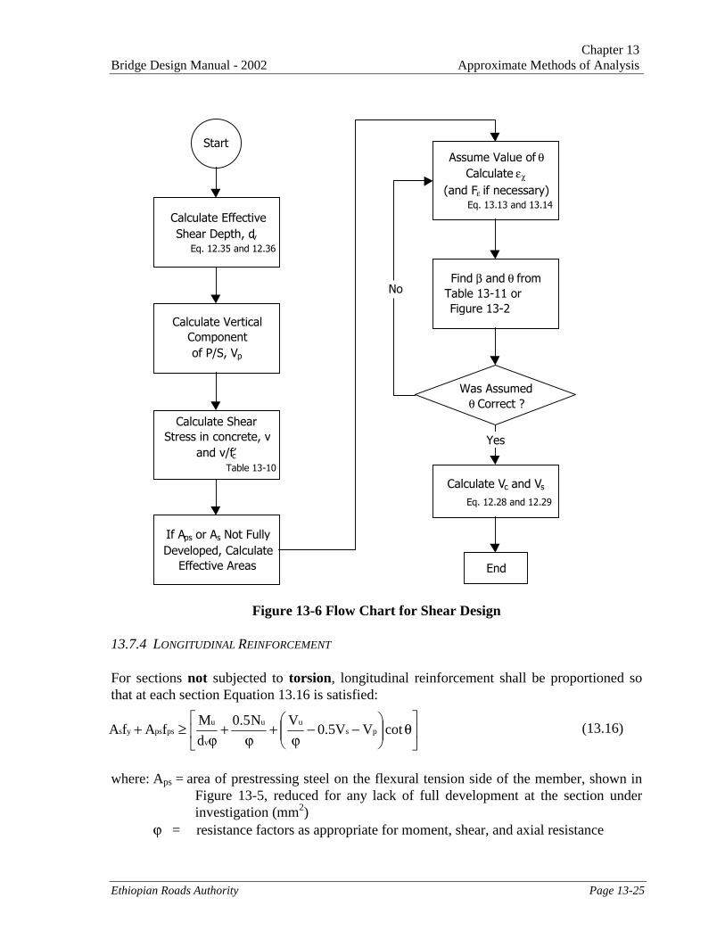
Because εx is a function of θ in Equation 13-13, and θ is related to εx in Tables 13-10 and 13-11 or Figures 13-3 and 13-4, an iterative solution is required. A flow chart for shear design isshown in Figure 13-6, which indicates the iterative solution for β using θ and εx.
The values of β and θ are based on calculating the stresses that can be transmitted acrossdiagonally cracked concrete. As the cracks become wider, the stress that can be transmitteddecreases. For members containing transverse reinforcement, it is assumed that the diagonalcracks will be spaced about 300 mm apart. For members without transverse reinforcement,the spacing of diagonal cracks inclined at θ° to the longitudinal reinforcement is assumed tobe sx/sinθ. Hence, deeper members having larger values of sx are assumed to have morewidely spaced cracks and, hence, cannot transmit such high shear stresses as shown in Figure13-7, which provides some guidance in the determination of the parameter sx.
c
ppcpepo
E
Efff +=
Chapter 13Bridge Design Manual - 2002 Approximate Methods of Analysis
Ethiopian Roads Authority Page 13-25
Figure 13-6 Flow Chart for Shear Design
13.7.4 LONGITUDINAL REINFORCEMENT
For sections not subjected to torsion, longitudinal reinforcement shall be proportioned sothat at each section Equation 13.16 is satisfied:
(13.16)
where: Aps = area of prestressing steel on the flexural tension side of the member, shown inFigure 13-5, reduced for any lack of full development at the section underinvestigation (mm2)
ϕ = resistance factors as appropriate for moment, shear, and axial resistance
��
���
��
�
�
�−−
ϕ+
ϕ+
ϕ≥+ cotVV5.0
VN5.0
d
MfAfA ps
uu
v
upspsys
Start
Calculate VerticalComponentof P/S, Vp
Calculate EffectiveShear Depth, dv
Eq. 12.35 and 12.36
Calculate ShearStress in concrete, v
and v/f′c Table 13-10
If Aps or As Not FullyDeveloped, Calculate
Effective Areas
Assume Value of θCalculate εχ
(and Fε if necessary) Eq. 13.13 and 13.14
Find β and θ fromTable 13-11 orFigure 13-2
Was Assumedθ Correct ?
Calculate Vc and Vs
Eq. 12.28 and 12.29
End
Yes
No

Chapter 13Approximate Methods of Analysis Bridge Design Manual - 2002
Page 13-26 Ethiopian Roads Authority
Figure 13-7 Guide to the Selection of Sx
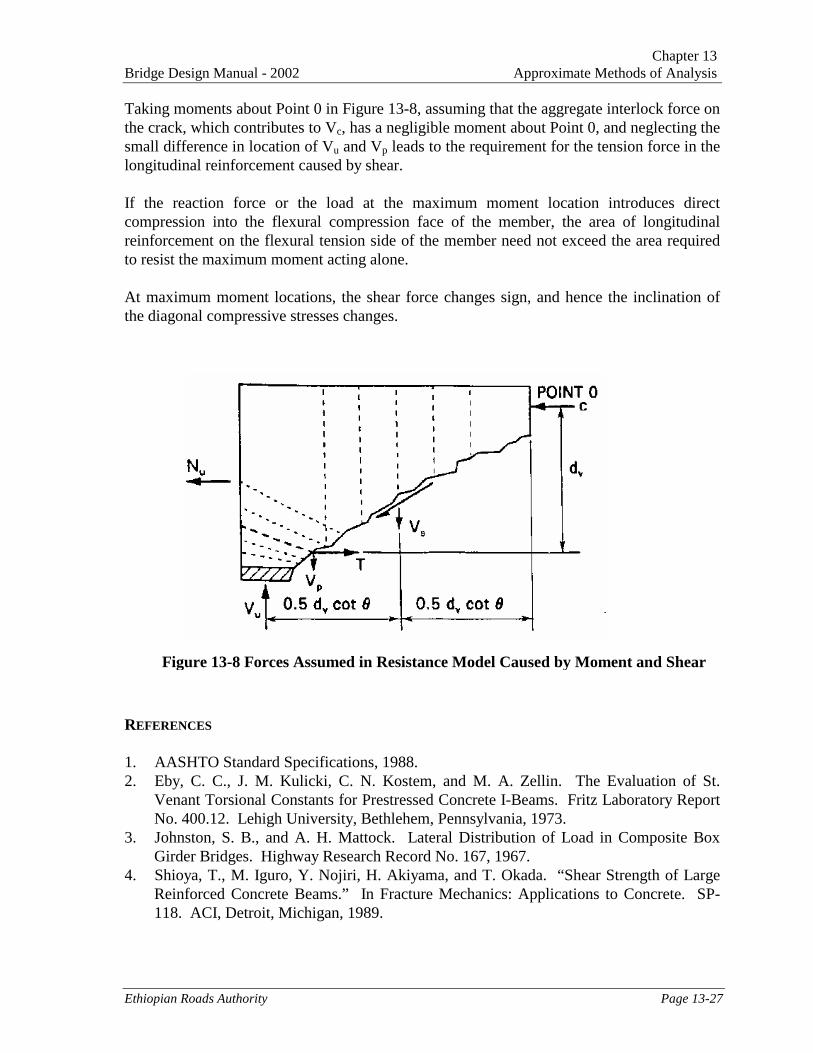
Shear causes tension in the longitudinal reinforcement. For a given shear, this tensionbecomes larger as θ becomes smaller and as Vc becomes larger. The tension in thelongitudinal reinforcement caused by the shear force can be, visualized from a free bodydiagram such as that shown in Figure 13-8.
Chapter 13Bridge Design Manual - 2002 Approximate Methods of Analysis
Ethiopian Roads Authority Page 13-27
Taking moments about Point 0 in Figure 13-8, assuming that the aggregate interlock force onthe crack, which contributes to Vc, has a negligible moment about Point 0, and neglecting thesmall difference in location of Vu and Vp leads to the requirement for the tension force in thelongitudinal reinforcement caused by shear.
If the reaction force or the load at the maximum moment location introduces directcompression into the flexural compression face of the member, the area of longitudinalreinforcement on the flexural tension side of the member need not exceed the area requiredto resist the maximum moment acting alone.
At maximum moment locations, the shear force changes sign, and hence the inclination ofthe diagonal compressive stresses changes.
REFERENCES
1. AASHTO Standard Specifications, 1988.2. Eby, C. C., J. M. Kulicki, C. N. Kostem, and M. A. Zellin. The Evaluation of St.
Venant Torsional Constants for Prestressed Concrete I-Beams. Fritz Laboratory ReportNo. 400.12. Lehigh University, Bethlehem, Pennsylvania, 1973.
3. Johnston, S. B., and A. H. Mattock. Lateral Distribution of Load in Composite BoxGirder Bridges. Highway Research Record No. 167, 1967.
4. Shioya, T., M. Iguro, Y. Nojiri, H. Akiyama, and T. Okada. “Shear Strength of LargeReinforced Concrete Beams.” In Fracture Mechanics: Applications to Concrete. SP-118. ACI, Detroit, Michigan, 1989.
Figure 13-8 Forces Assumed in Resistance Model Caused by Moment and Shear