Embed Size (px)
Citation preview

INTELLI-RV12V POWER MANAGEMENT SYSTEM
P/No. PM200

IMPORTANT SAFETY INFORMATIONPlease read this manual thoroughly before use and store in a safe place for future reference.
WARNINGS
• Explosive gases. Prevent flames and sparks. Provide adequate ventilation during charging
• Before charging, read the instructions
• For indoor use. Do not expose to rain
• For charging lead acid and LiFePO4 BATTERIES ONLY (of the size & voltage specified in the specifications table)
• Always charge the battery on the correct voltage setting. Never set the charger to a higher voltage than the battery
• Disconnect the 240V mains supply before making or breaking the connections to the battery
• The battery charger must be plugged into an earthed socket outlet
• Connection to supply mains is to be in accordance with National wiring rules
• Do not attempt to charge non-rechargeable batteries
• Never charge a frozen battery
• I f the AC cord is damaged, do not attempt to use. It must be replaced or repaired by a qualified person
• Corrosive substances may escape from the battery during charging and damage delicate surfaces. Store and charge in a suitable area
• Where possible, ensure all vehicle accessories including lights, heaters, appliances etc. are turned off prior to charging
• This charger is not intended for use by persons (including children) with reduced physical, sensory or mental capabilities, or lack of experience and knowledge, unless they have been given supervision or instruction concerning the use of the appliance by a person responsible for their safety
• Young children should be supervised to ensure that they do not play with the appliance
• If the recreational vehicle is to be put in to storage without power, please turn off the BATTERY MASTER SWITCH. If the recreational vehicle is to be put in to long term storage without power, disconnect ALL cabling from the battery.
2
3
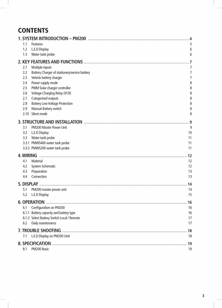
CONTENTS1. SYSTEM INTRODUCTION – PM200 ...........................................................................................4
1.1 Features 51.2 L.E.D Display 61.3 Water tank probe 6
2. KEY FEATURES AND FUNCTIONS ...............................................................................................72.1 Multiple inputs 72.2 Battery Charger of stationery/service battery 72.3 Vehicle battery charger 72.4 Power supply mode 82.5 PWM Solar charger controller 82.6 Voltage Charging Relay (VCR) 82.7 Categorised outputs 82.8 Battery Low Voltage Protection 82.9 Manual Battery switch 82.10 Silent mode 8
3. STRUCTURE AND INSTALLATION ...............................................................................................93.1 PM200 Master Power Unit 93.2 L.E.D Display 103.3 Water tank probe 113.3.1 PMWS400 water tank probe 113.3.2 PMWS200 water tank probe 11
4. WIRING .....................................................................................................................................124.1 Material 124.2 System Schematic 124.3 Preparation 134.4 Connection 13
5. DISPLAY .....................................................................................................................................145.1 PM200 master power unit 145.2 L.E.D Display 15
6. OPERATION ...............................................................................................................................166.1 Configuration on PM200 166.1.1 Battery capacity and battery type 166.1.2 Select Battery Switch Local / Remote 176.2 Daily maintenance 17
7. TROUBLE SHOOTING .................................................................................................................187.1 L.E.D Display on PM200 Unit 18
8. SPECIFICATION ..........................................................................................................................198.1 PM200 Basic 19
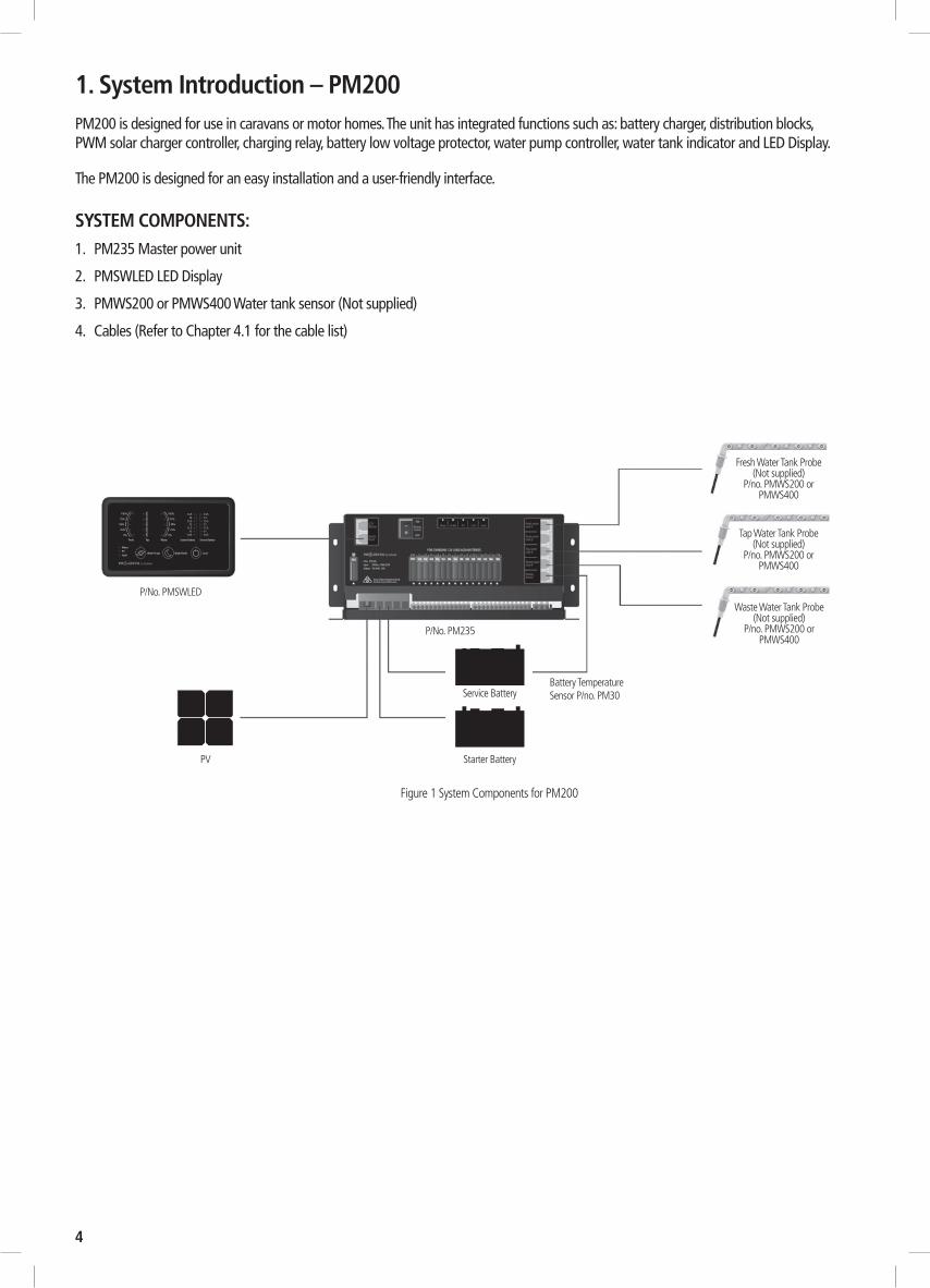
1. System Introduction – PM200PM200 is designed for use in caravans or motor homes. The unit has integrated functions such as: battery charger, distribution blocks, PWM solar charger controller, charging relay, battery low voltage protector, water pump controller, water tank indicator and LED Display.
The PM200 is designed for an easy installation and a user-friendly interface.
SYSTEM COMPONENTS:1. PM235 Master power unit
2. PMSWLED LED Display
3. PMWS200 or PMWS400 Water tank sensor (Not supplied)
4. Cables (Refer to Chapter 4.1 for the cable list)
4
Fresh Water Tank Probe(Not supplied)
P/no. PMWS200 or PMWS400
Tap Water Tank Probe(Not supplied)
P/no. PMWS200 or PMWS400
Waste Water Tank Probe(Not supplied)
P/no. PMWS200 or PMWS400
Service BatteryBattery Temperature Sensor P/no. PM30
Starter Battery
Figure 1 System Components for PM200
P/No. PM235
P/No. PMSWLED
PV
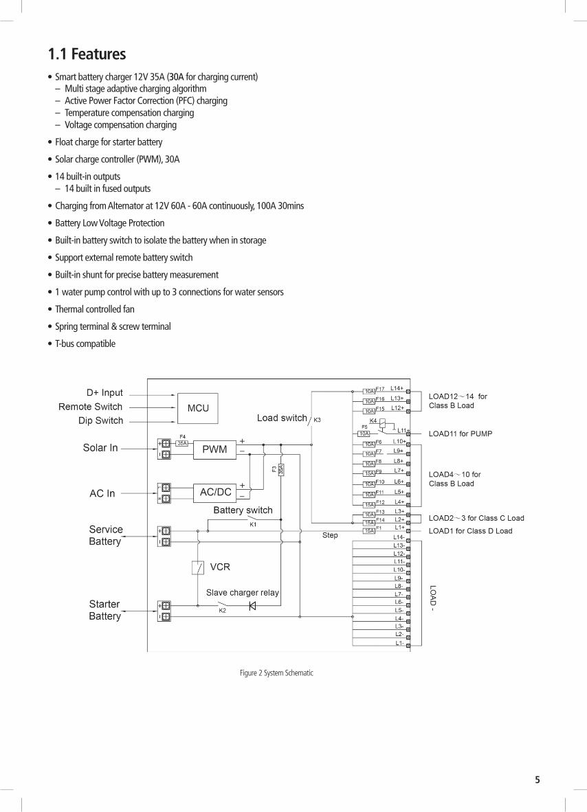
1.1 Features• Smart battery charger 12V 35A (30A for charging current)
– Multi stage adaptive charging algorithm– Active Power Factor Correction (PFC) charging– Temperature compensation charging– Voltage compensation charging
• Float charge for starter battery
• Solar charge controller (PWM), 30A
• 14 built-in outputs– 14 built in fused outputs
• Charging from Alternator at 12V 60A - 60A continuously, 100A 30mins
• Battery Low Voltage Protection
• Built-in battery switch to isolate the battery when in storage
• Support external remote battery switch
• Built-in shunt for precise battery measurement
• 1 water pump control with up to 3 connections for water sensors
• Thermal controlled fan
• Spring terminal & screw terminal
• T-bus compatible
Figure 2 System Schematic
5

6
1.2 L.E.D Display
Figure 3 PMSWLED switch panel
Table 1 Front panel of PMSWLED
Table 2 LED indication of PM260
1.3 Water Tank ProbeFor PM200, max three probes can be controlled in the system.
NOTE: Always check the probe required for the water tank before purchase. If the probe included does not fit the water tank, please contact the seller.
There are 2 probe styles:
PMWS200: PMWS400:• Side installation • Side installation• Suitable for water tank • Suitable for water tank• Depth >200mm • Depth 300-400mm
Figure 4 PMWS200Figure 5 PMWS400
NO LABEL TYPE DESCRIPTION
1 Water pump DC load control Load control, on/off control
2 Night mode Scene mode Refer to 2.10
3 Load DC load control Load control, on/off control. Refer to 2.7
4 Fresh water tank Sensor Detect the level of fresh water tank
5 Tap water tank Sensor Detect the level of tap water tank
6 Waste water tank Sensor Detect the level of waste water tank
7 Starter battery Voltage Detect the voltage of starter battery
8 Service battery Voltage Detect the voltage of service battery
NO LABEL COLOUR STATUS DESCRIPTION
1 Main GreenON Battery charged or power supply mode
Flash Battery charging under grid electricity
OFF NO AC input
2 PV GreenSolid Battery charged
Flash Battery charging under solar energy
OFF NO solar input / AC charging / Aux charging
3 Fault Red
ON Short circuit
1 flash Service battery voltage low
2 flash Service battery voltage high
3 flash Over temp (heat sink)
4 flash Bulk charge timeout
5 flash VCR anomaly
6 flash Over temp (environment)

2. KEY FEATURES AND FUNCTIONS
AC MAINS X XSOLAR X XAUXILIARY X XDOMINATING SOURCE AC MAINS AC MAINS AUX
Table 3 Source priority
Figure 6 Charging Algorithm
Icc is the rated current.
2.2 Battery Charger Of Stationery/Service BatteryThe charger automatically starts when the appropriate qualified power is connected, either from grid, generator or solar.
With multiple charging stages (soft start-bulk absorption float-recycle), PM200 is designed to fully charge battery quickly. To guarantee the optimal charging for batteries of different states, the PM200 features Microprocessor-controlled charging algorithm. The Float and Recycle charging programs guarantees that the battery condition does not change despite being connected for a longer period.
Battery temperature compensation chargingThe BTS PM30 (Battery Temperature Sensor) supplied with PM200, measures the temperature of the battery and automatically adjusts, in real time, to charge the battery properly at compensation rate of – 4mv±10%/°C/cell. In case BTS is not present, the PM200 will use 25°C as default.
Voltage compensation chargingWith a voltage sensor PM30 the PM200 can, if required, automatically adjust its output to compensate the voltage drop caused by a cable. This assures the right voltage is being delivered for optimal charging.
Adjustable charging capacity Users can adjust the charging current by specifying the battery capacity. The charging current is set at threshold rate of 10% the of the battery capacity (I = 0.1C) by default.
Lithium battery chargingThe PM200 can be configured to charge Lithium battery. With the Lithium battery, the max charging current will automatically be set at 30% of battery capacity (Imax=0.3C).
2.3 Vehicle Battery ChargerAlong with a powerful charger for service battery, PM200 offers a float charge of up to 3A to keep the starter battery charged, whether connected to the AC main or PV. When starter battery is less than 12.4V, the PM200 starts charging after 30 minutes delay and stops charging when voltage reaches 12.8V.
2.4 Power Supply ModeIf no battery is attached to PM200 unit, it will work as a power supply automatically with a 12.8VDC output.
7
½ lcc
lcc
11.5V
10 days 1 hr 5mins
SOFT STARTSTAGE
CURRENT
VOLTAGE
BULK ABSORPTION FLOAT RECYCLE
1 2 3 4 5
1 SOFT STARTIncreases battery life by gently starting to charge the battery 50% of bulk
2 BULK Reduces charging time by delivering maximum charge to set voltage
3 ABSORPTIONEnsures a full charge to the battery without overcharging
4 FLOATFloat charge maintains the battery at 100% charge
5 RECYCLE
2.1 Multiple InputsPM200 master power unit may have many sources at one time. These sources include the AC mains, solar panel and starter battery (Auxiliary). Only one of them will be dominated to provide power at one time, even if all are available, priorities are listed to the right.

2.8 Battery Low Voltage Protection (BLVP or commonly know as an LVD)PM200 master power unit has a built-in low voltage protection relay. It will disconnect the load once the battery voltage drops below the threshold voltage. The default setting is 10.5VDC.
2.9 Manual Battery SwitchThe PM200 unit offers a convenient way to switch off the output of the service battery on-board. It protects the service battery from being drained by electronics on board, completely isolating the battery. PM200 unit also supports a remote manual battery switch. Before using the remote switch, ensure the ‘switch selector’ is set to ‘Remote’. The switch is only effective when the system has no other energy resource for the load except the battery.
2.10 Silent ModeIn Silent Mode, the backlight of the Led Display and the fan will be turned off or decreased in speed.
8
Figure 7 Categorised output
Table 4 Categorised outputs definition
CATEGORY QTY DESCRIPTION POSSIBLE LOAD SUITABLE
Class A1 1 Relay controlled output with fuse, protected by main master switch relay Water pump
Class B 10 Fused outputs, protected by master switch relay Ventilation fan etc
Class C 2 Live load Fridge, security alarm etc.
Class D 1 Permanent on load Auto step
2.5 PWM Solar charger controllerPM200 has a built-in PWM charger for the service battery.• Max input voltage 25VDC
• Max charging current 30A• Max supply current 30A
2.6 Voltage Charging Relay (VCR or commonly known as a VSR)PM200 Master Power Unit has a built-in voltage charging relay (VCR), which offers a convenient source to charge the service battery by alternator whilst the engine is running.LEAD ACID BATTERY -- When the start battery reaches 13.4VDC with threshold time delay, the VCR will charge the service battery from the alternator. VCR will continue charging until the starter battery voltage drops under 12.8VDC.LiFePO4 LITHIUM BATTERY -- When the starter battery reaches 14.0VDC with threshold time delay, the VCR will charge the service battery from the alternator. The VCR will continue charging until the starter battery voltage drops below 13.5VDC with less than 2A charge to the service battery with threshold time delay.NOTE: The PM200, when charging from the starter battery, does not provide 5 stage charging.
It simply takes whatever power and charging is available from the alternator.NOTE: If your vehicle is fitted with a smart charging system (Variable Voltage or Temperature Compensating), the VCR charge system may not function correctly and a DC-DC Charging system is recommended.Please consult your local dealer or installer for further information.
2.7 Categorised OutputsThe 14 outputs are categorised into groups and controls as per below:

Figure 8 Front panel of PM235
9
Table 5 Connection of PM235CATEGORY QTY DESCRIPTION POSSIBLE LOAD SUITABLE
Class A1 1 Relay controlled output with fuse, protected by main master switch relay Water pump
Class B 10 Fused outputs, protected by master switch relay Ventilation fan etc
Class C 2 Live load Fridge, security alarm etc.
Class D 1 Permanent on load Auto step
NO LABEL DEFINITION DESCRIPTION
1 AC Mains AC input port
2 Switch panel Comm port Connect to switch panel
3 LCD Display Comm port Connect to monitor (Monitor is not available in PM200)
4 Battery switch Service battery switch Manual battery switch
5 Fresh water tank 1 Connect to fresh water tank 1
6 Fresh water tank 2 Fresh water tank 2 is not available in PM200
7 Tap water tank Connect to tap water tank
8 Waste water tank Connect to waste water tank
9 Battery sensor For temp compensation Connect to service battery+
10 PV+ Solar input Connect to PV+
11 PV- Solar input Connect to PV-
12 Starter Bat+ Starter battery+ Connect to starter battery+ <20Vdc
13 Service Bat+ Service battery+ Connect to service battery+ <20Vdc
14 Starter Bat- Starter battery- Connect to starter battery-
15 Service Bat- Service battery- Connect to service battery-
16 L1+ Step Connect to load of class D
17 L2+ ~ L3+ Connect to load of class C
18 L4+ ~ L10+ Connect to load of class B
19 L11+ Water pump Connect to Water pump+
20 L12+ ~ L14+ Connect to load of class B
21 L1- ~ L14- Connect to DC load -
22 D+ Point D+ input Connect to D+
23 Remote Switch Terminal block Connect to remote switch
24 Select Switch Dip switch Select local switch or remote switch (Note: open the upper cover board to operate)
25 Setting Dip switch Set the battery type and capacity (Note: open the upper cover board to operate)
26 Fuse Fuses and fuse failure indication
3. STRUCTURE AND INSTALLATION3.1 PM200 Master Power Unit
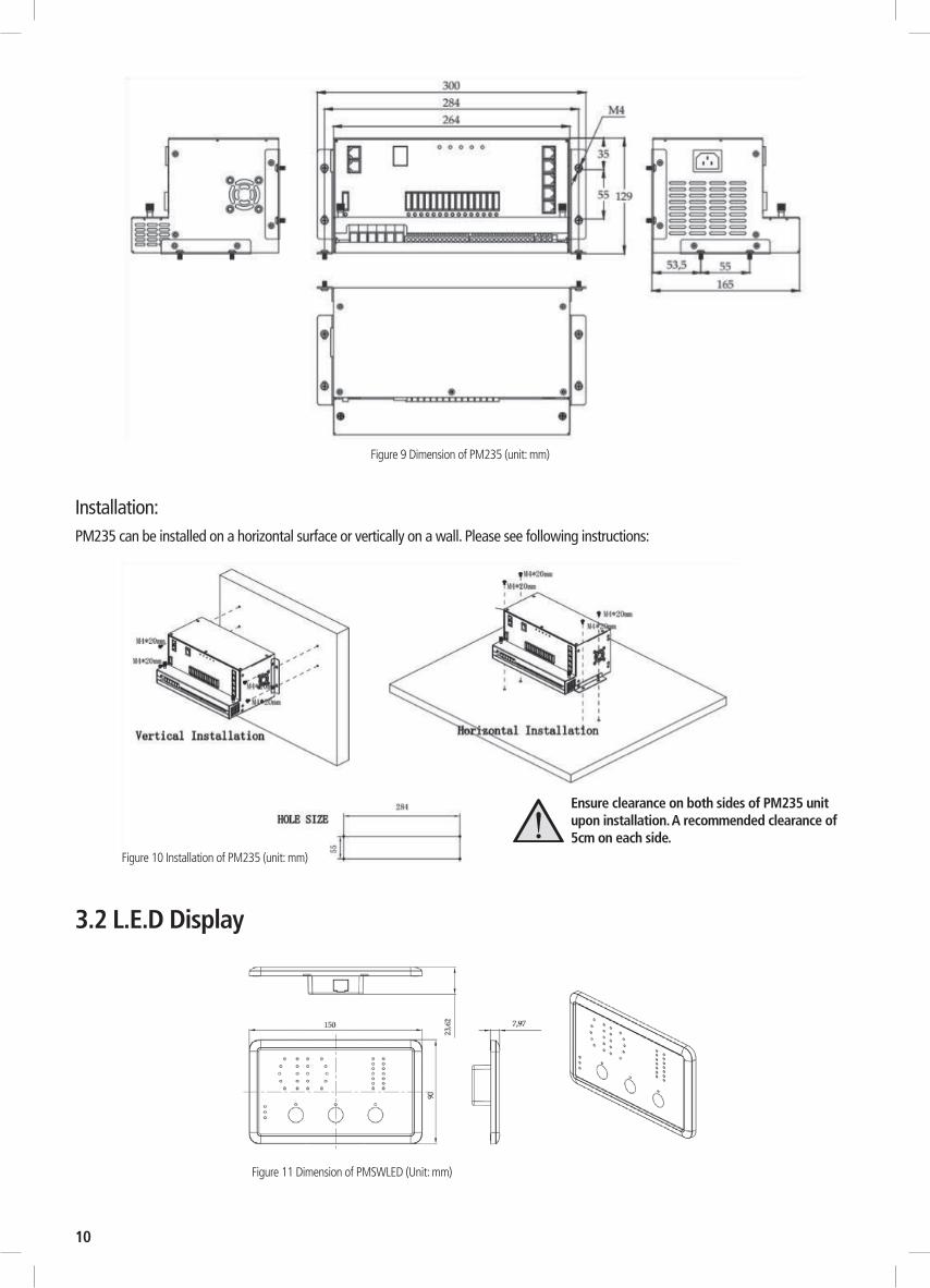
3.2 L.E.D Display
Figure 11 Dimension of PMSWLED (Unit: mm)
10
Installation:PM235 can be installed on a horizontal surface or vertically on a wall. Please see following instructions:
Figure 10 Installation of PM235 (unit: mm)
Ensure clearance on both sides of PM235 unit upon installation. A recommended clearance of 5cm on each side.
Figure 9 Dimension of PM235 (unit: mm)
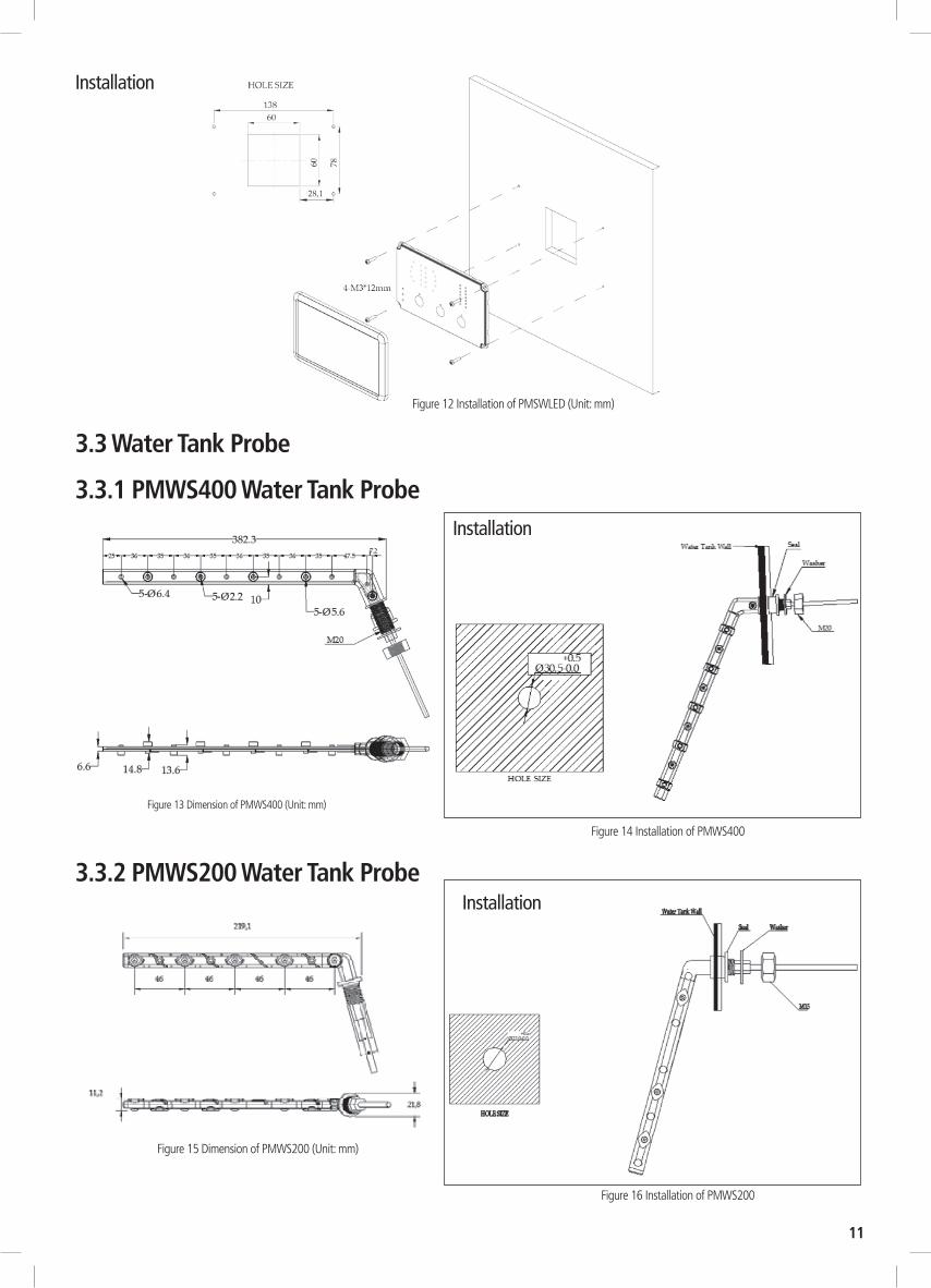
Figure 12 Installation of PMSWLED (Unit: mm)
3.3 Water Tank Probe
3.3.1 PMWS400 Water Tank Probe
Figure 13 Dimension of PMWS400 (Unit: mm)
Figure 14 Installation of PMWS400
11
3.3.2 PMWS200 Water Tank ProbeInstallation
Figure 15 Dimension of PMWS200 (Unit: mm)
Figure 16 Installation of PMWS200
Installation
Installation

12
Figure 17 System Diagram
4. WIRING4.1 Material
COD
EN
AME
MO
DEL
/LEN
GTH
QTY
P/N
O. O
N
DRA
WIN
G
1Ca
rava
n M
aste
r Pow
erPM
235
11
2M
embr
ane
Switc
h Pa
nel
PMSW
LED
13
3Fr
esh
wat
er ta
nk le
vel s
enso
rNo
t inc
lude
d an
d to
be
orde
red
sepa
rate
ly
04
4Ta
p w
ater
tank
leve
l sen
sor
06
5W
aste
wat
er ta
nk le
vel s
enso
r0
7
6PV
09
COD
EN
AME
MO
DEL
/LEN
GTH
QTY
P/N
O. O
N
DRA
WIN
G
7Sw
itch
pane
l lin
e5m
1PM
SWLE
DC
8Ba
ttery
sens
or li
ne3m
1PM
BS
9W
ater
tank
pro
be li
ne4m
0PM
WS2
00 /
PMW
S400
10W
ater
tank
pro
be li
ne4m
0
11W
ater
tank
pro
be li
ne4m
0
12Po
wer
Cab
le1.
5m1
PMAC
Tabl
e 6
Com
pone
nts l
ist o
f PM
200
4.2 System Schematic
Sola
r
Switc
h Pa
nel
PMW
S200
/ PM
WS4
00PM
WS2
00 /
PMW
S400
PMW
S200
/ PM
WS4
00
PMBS
PMAC
PMSW
LEDC
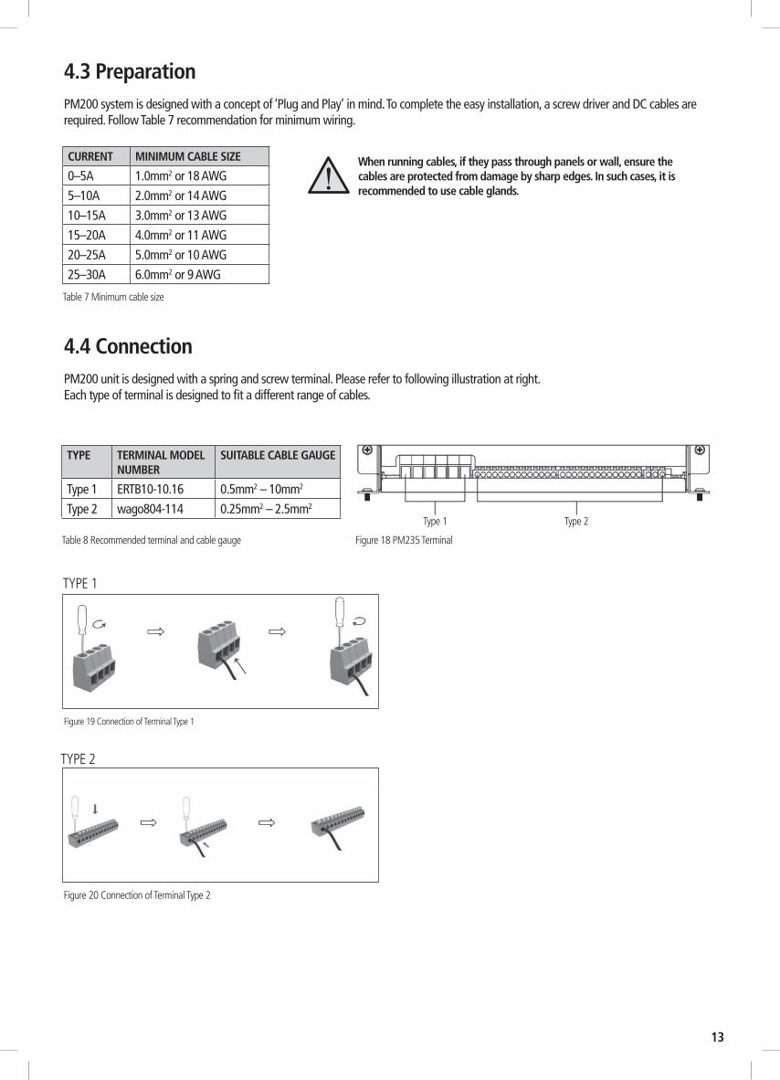
4.3 PreparationPM200 system is designed with a concept of ‘Plug and Play’ in mind. To complete the easy installation, a screw driver and DC cables are required. Follow Table 7 recommendation for minimum wiring.
4.4 ConnectionPM200 unit is designed with a spring and screw terminal. Please refer to following illustration at right. Each type of terminal is designed to fit a different range of cables.
Table 8 Recommended terminal and cable gauge Figure 18 PM235 Terminal
TYPE TERMINAL MODEL NUMBER
SUITABLE CABLE GAUGE
Type 1 ERTB10-10.16 0.5mm2 – 10mm2
Type 2 wago804-114 0.25mm2 – 2.5mm2
Figure 19 Connection of Terminal Type 1
13
When running cables, if they pass through panels or wall, ensure the cables are protected from damage by sharp edges. In such cases, it is recommended to use cable glands.
TYPE 1
TYPE 2
Figure 20 Connection of Terminal Type 2
CURRENT MINIMUM CABLE SIZE
0–5A 1.0mm2 or 18 AWG
5–10A 2.0mm2 or 14 AWG
10–15A 3.0mm2 or 13 AWG
15–20A 4.0mm2 or 11 AWG
20–25A 5.0mm2 or 10 AWG
25–30A 6.0mm2 or 9 AWG
Table 7 Minimum cable size
Type 1 Type 2

14
No. LED COLOUR STATUS DESCRIPTION
1 Mains GREEN
ON AC input OK
OFF AC disconnected
Quick flashing (flash twice every second) AC input abnormal
2 Str Bat GREEN
ON Str Bat charging the battery
Slow flashing (flash once every second) The input of the Aux is normal but it is charged by the AC
Quick flashing (flash twice every second) Str Bat input error
OFF Str Bat disconnected
3 PV GREEN
ON PV charging the battery
Slow flashing (flash once every second) The input voltage of the PV is normal but it is charged by the AC or Starter battery
Quick flashing (flash twice every second) PV input error
OFF PV disconnected
4 CHG GREEN
ON Battery charged
Flashing (flash once every second) Battery charging
Slow flashing (1 second on 2 seconds off) Battery discharge
OFF Battery disconnect
5 FAULT RED
ON Short circuit
1 flash Service battery voltage low
2 flash Service battery voltage high
3 flash Over temp (heat sink)
4 flash Bulk charge timeout
5 flash VCR anomaly
6 flash Over temp (Ambient)
Table 9 LED indicator description of PM235
Figure 21 An overview of PM235
5. DISPLAY5.1 PM235 Master Power Unit
15
No. LED COLOUR STATUS DESCRIPTION
1 Mains GREEN
ON AC input OK
OFF AC disconnected
Quick flashing (flash twice every second) AC input abnormal
2 Str Bat GREEN
ON Str Bat charging the battery
Slow flashing (flash once every second) The input of the Aux is normal but it is chargedby the AC
Quick flashing (flash twice every second) Str Bat input error
OFF Str Bat disconnected
3 PV GREEN
ON PV charging the battery
Slow flashing (flash once every second) The input voltage of the PV is normal but it ischarged by the AC or Starter battery
Quick flashing (flash twice every second) PV input error
OFF PV disconnected
4 CHG GREEN
ON Battery charged
Flashing (flash once every second) Battery charging
Slow flashing (1 second on 2 seconds off) Battery discharge
OFF Battery disconnect
5 FAULT RED
ON Short circuit
1 flash Service battery voltage low
2 flash Service battery voltage high
3 flash Over temp (heat sink)
4 flash Bulk charge timeout
5 flash VCR anomaly
6 flash Over temp (Ambient)
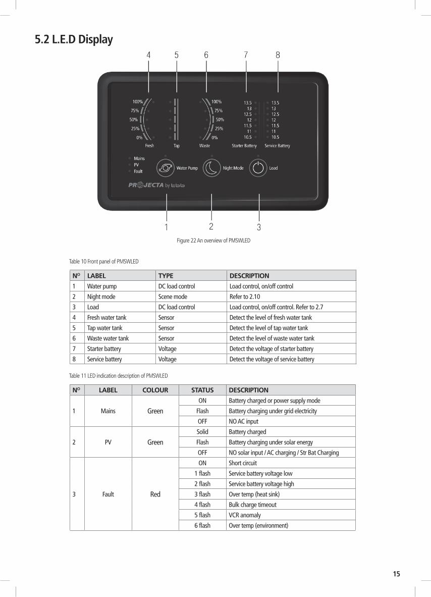
5.2 L.E.D Display
Figure 22 An overview of PMSWLED
Table 10 Front panel of PMSWLED
Table 11 LED indication description of PMSWLED
NO LABEL TYPE DESCRIPTION
1 Water pump DC load control Load control, on/off control
2 Night mode Scene mode Refer to 2.10
3 Load DC load control Load control, on/off control. Refer to 2.7
4 Fresh water tank Sensor Detect the level of fresh water tank
5 Tap water tank Sensor Detect the level of tap water tank
6 Waste water tank Sensor Detect the level of waste water tank
7 Starter battery Voltage Detect the voltage of starter battery
8 Service battery Voltage Detect the voltage of service battery
NO LABEL COLOUR STATUS DESCRIPTION
1 Mains GreenON Battery charged or power supply mode
Flash Battery charging under grid electricity
OFF NO AC input
2 PV GreenSolid Battery charged
Flash Battery charging under solar energy
OFF NO solar input / AC charging / Str Bat Charging
3 Fault Red
ON Short circuit
1 flash Service battery voltage low
2 flash Service battery voltage high
3 flash Over temp (heat sink)
4 flash Bulk charge timeout
5 flash VCR anomaly
6 flash Over temp (environment)

16
Figure 23 Dip Switch of PM200 Table 12 Dip Switch definition
6. OPERATION
6.1 Configuration on PM200You could configure the battery type and capacity through PM235 master power unit.
6.1.1 Battery Capacity and Battery TypeThere is a dip switch for you to set battery capacity and battery type.
DIP SWITCH
1 2 3 4
Battery Type
Dip switch definitions:
Table 13 Battery Capacity setting by dip switch
Table 15 Factory default setting
DIP SWITCH 1 2 3 4STATUS OFF OFF OFF OFF
Factory default setting:
Configure the max charging current of PM235:
Configure the battery type connected:
When choosing max charging current, please take into consideration the consumption of the DC load connected with the system.
DS3 DS4 BATTERY TYPE
ABSORPTION FLOAT
OFF OFF AGM 14.4V 13.5V
OFF ON GEL 14.1V 13.5V
ON OFF LiFePO4 14.4V 13.5V
ON ON WET 14.7V 13.7V
Table 14 Battery Type setting by dip switch
1 2 3 4
ON
OFF
LEAD ACID LITHIUM
DS1 DS2 AC CHARGE SOLAR CHARGE
ON ON 10A 20A 30A
ON OFF 15A 30A 30A
OFF ON 20A 30A 30A
OFF OFF 30A 30A 30A
AC / SOLAR CHARGE
17
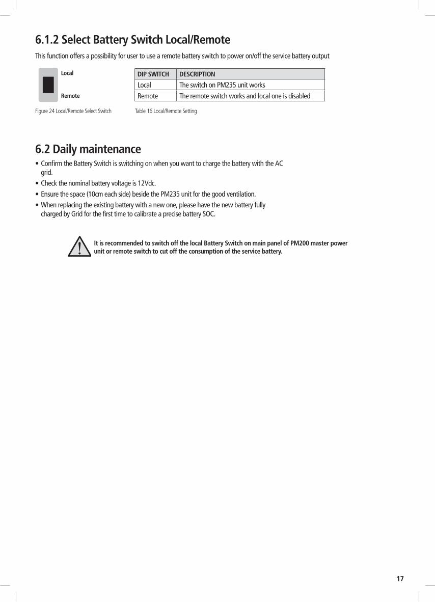
6.2 Daily maintenance • Confirm the Battery Switch is switching on when you want to charge the battery with the AC
grid. • Check the nominal battery voltage is 12Vdc.• Ensure the space (10cm each side) beside the PM235 unit for the good ventilation.• When replacing the existing battery with a new one, please have the new battery fully
charged by Grid for the first time to calibrate a precise battery SOC.
DIP SWITCH DESCRIPTION
Local The switch on PM235 unit works
Remote The remote switch works and local one is disabled
Figure 24 Local/Remote Select Switch Table 16 Local/Remote Setting
Local
Remote
6.1.2 Select Battery Switch Local/RemoteThis function offers a possibility for user to use a remote battery switch to power on/off the service battery output
It is recommended to switch off the local Battery Switch on main panel of PM200 master power unit or remote switch to cut off the consumption of the service battery.
18
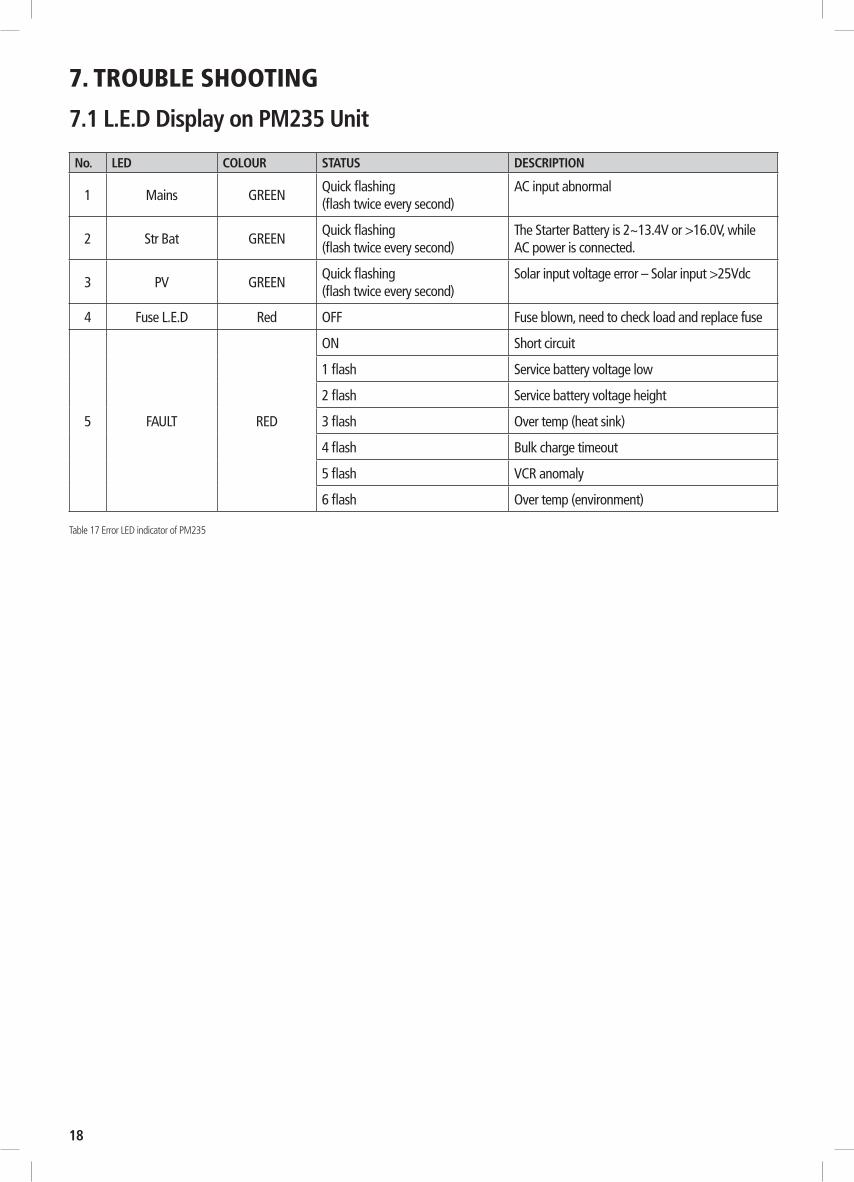
7. TROUBLE SHOOTING
7.1 L.E.D Display on PM235 Unit
No. LED COLOUR STATUS DESCRIPTION
1 Mains GREENQuick flashing (flash twice every second)
AC input abnormal
2 Str Bat GREENQuick flashing (flash twice every second)
The Starter Battery is 2~13.4V or >16.0V, while AC power is connected.
3 PV GREENQuick flashing (flash twice every second)
Solar input voltage error – Solar input >25Vdc
4 Fuse L.E.D Red OFF Fuse blown, need to check load and replace fuse
5 FAULT RED
ON Short circuit
1 flash Service battery voltage low
2 flash Service battery voltage height
3 flash Over temp (heat sink)
4 flash Bulk charge timeout
5 flash VCR anomaly
6 flash Over temp (environment)
Table 17 Error LED indicator of PM235
19
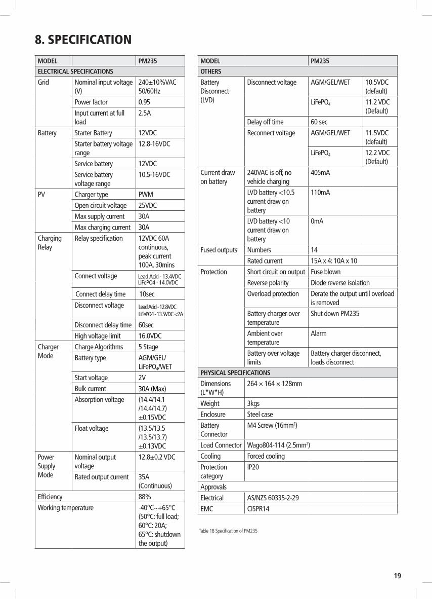
8. SPECIFICATION
Table 18 Specification of PM235
MODEL PM235
ELECTRICAL SPECIFICATIONS
Grid Nominal input voltage (V)
240±10%VAC 50/60Hz
Power factor 0.95
Input current at full load
2.5A
Battery Starter Battery 12VDC
Starter battery voltage range
12.8-16VDC
Service battery 12VDC
Service battery voltage range
10.5-16VDC
PV Charger type PWM
Open circuit voltage 25VDC
Max supply current 30A
Max charging current 30A
Charging Relay
Relay specification 12VDC 60A continuous, peak current 100A, 30mins
Connect voltage
Connect delay time 10sec
Disconnect voltage
Disconnect delay time 60sec
High voltage limit 16.0VDC
Charger Mode
Charge Algorithms 5 Stage
Battery type AGM/GEL/LiFePO4/WET
Start voltage 2V
Bulk current 30A (Max)Absorption voltage (14.4/14.1
/14.4/14.7) ±0.15VDC
Float voltage (13.5/13.5 /13.5/13.7) ±0.13VDC
Power Supply Mode
Nominal output voltage
12.8±0.2 VDC
Rated output current 35A (Continuous)
Efficiency 88%
Working temperature -40°C~+65°C(50°C: full load; 60°C: 20A; 65°C: shutdownthe output)
MODEL PM235
OTHERS
Battery Disconnect (LVD)
Disconnect voltage AGM/GEL/WET 10.5VDC (default)
LiFePO4 11.2 VDC (Default)
Delay off time 60 sec
Reconnect voltage AGM/GEL/WET 11.5VDC (default)
LiFePO4 12.2 VDC (Default)
Current draw on battery
240VAC is off, no vehicle charging
405mA
LVD battery <10.5 current draw on battery
110mA
LVD battery <10 current draw on battery
0mA
Fused outputs Numbers 14
Rated current 15A x 4: 10A x 10
Protection Short circuit on output Fuse blown
Reverse polarity Diode reverse isolation
Overload protection Derate the output until overload is removed
Battery charger over temperature
Shut down PM235
Ambient over temperature
Alarm
Battery over voltage limits
Battery charger disconnect, loads disconnect
PHYSICAL SPECIFICATIONS
Dimensions (L*W*H)
264 × 164 × 128mm
Weight 3kgs
Enclosure Steel case
Battery Connector
M4 Screw (16mm2)
Load Connector Wago804-114 (2.5mm2)
Cooling Forced cooling
Protection category
IP20
Approvals
Electrical AS/NZS 60335-2-29
EMC CISPR14
Lead Acid - 13.4VDCLiFePO4 - 14.0VDC
Lead Acid - 12.8VDCLiFePO4 - 13.5VDC <2A
WARRANTY STATEMENT
Applicable only to product sold in Australia
Brown & Watson International Pty Ltd of 1500 Ferntree Gully Road, Knoxfield, Vic.,telephone (03) 9730 6000, fax (03) 9730 6050, warrants that all products described in its current catalogue (save and except for all bulbs and lenses whether made of glass or some other substance) will under normal use and service be free of failures in material and workmanship for a period of one (1) year (unless this period has been extended as indicated elsewhere) from the date of the original purchase by the consumer as marked on the invoice. This warranty does not cover ordinary wear and tear, abuse, alteration of products or damage caused by the consumer.
To make a warranty claim the consumer must deliver the product at their cost to the original place of purchase or to any other place which may be nominated by either BWI or the retailer from where the product was bought in order that a warranty assessment may be performed. The consumer must also deliver the original invoice evidencing the date and place of purchase together with an explanation in writing as to the nature of the claim.
In the event that the claim is determined to be for a minor failure of the product then BWI reserves the right to repair or replace it at its discretion. In the event that a major failure isdetermined the consumer will be entitled to a replacement or a refund as well as compensation for any other reasonably foreseeable loss or damage. This warranty is in addition to any other rights or remedies that the consumer may have under State or Federal legislation.
IMPORTANT NOTEOur goods come with guarantees that cannot be excluded under the Australian Consumer Law. You are entitled to a replacement or refund for a major failure and compensation for any other reasonably foreseeable loss or damage. You are also entitled to have the goods repaired or replaced if the goods fail to be of acceptable quality and the failure does not amount to a major failure.
Distributed by
AUSTRALIA
Brown & Watson International Pty LtdKnoxfield, Victoria 3180Telephone (03) 9730 6000Facsimile (03) 9730 6050National Toll Free 1800 113 443
NEW ZEALAND
Narva New Zealand Ltd
22–24 Olive RoadPO Box 12556 PenroseAuckland, New ZealandTelephone (09) 525 4575Facsimile (09) 579 1192
IS402
Issue 28/08/19