Embed Size (px)
Citation preview
2
12AT/50AT SeriesSpin-On Filters
Applications forSpin-On Filters
• Mobile Equipment
• Hydrostatic Drives
• Industrial Power Units
• Reservoir Breathers
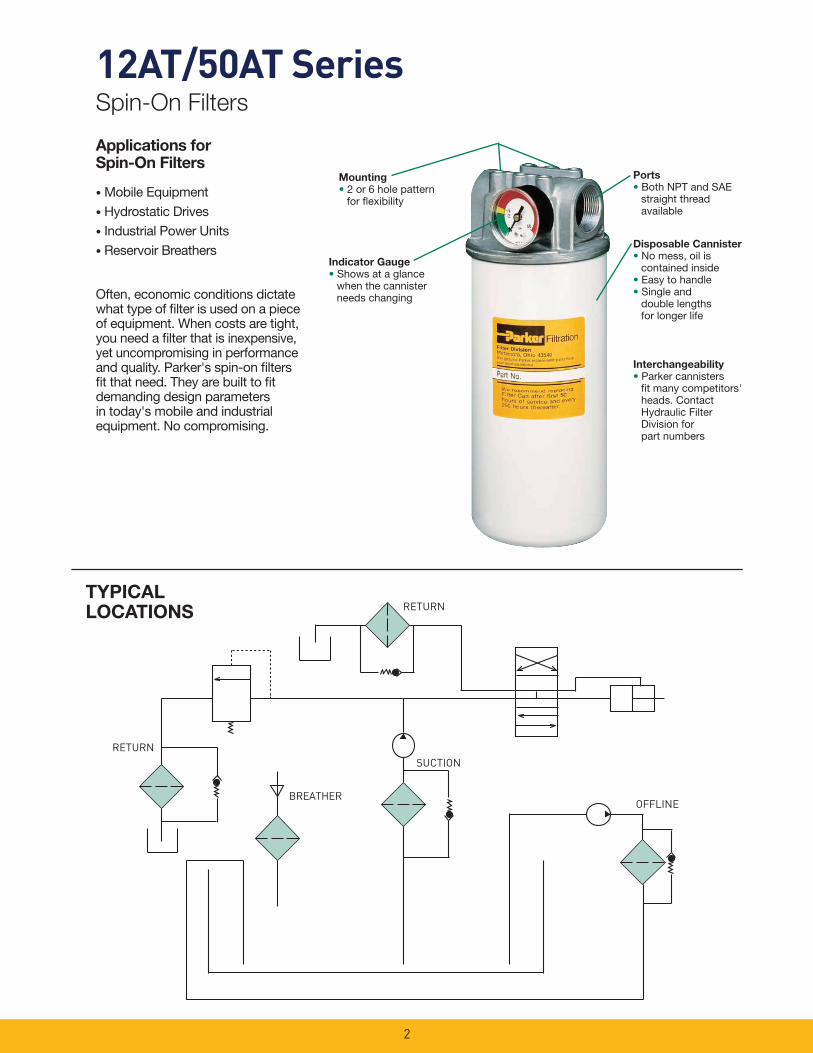
Often, economic conditions dictate what type of fi lter is used on a piece of equipment. When costs are tight, you need a fi lter that is inexpensive, yet uncompromising in performance and quality. Parker's spin-on fi lters fi t that need. They are built to fi t demanding design parameters in today's mobile and industrial equipment. No compromising.
Mounting
• 2 or 6 hole pattern for fl exibility
Indicator Gauge
• Shows at a glance when the cannister needs changing
BREATHER
RETURN
RETURNSUCTION
OFFLINE
TYPICAL LOCATIONS
Disposable Cannister
• No mess, oil is contained inside• Easy to handle• Single and
double lengths for longer life
Ports
• Both NPT and SAE straight thread available
Interchangeability
• Parker cannisters fi t many competitors' heads. Contact Hydraulic Filter Division for part numbers

3
03C 10C 25C
10B 20B
(PSI
)P
RES
SUR
E D
RO
P(B
AR)
(GPM) FLOW (LPM)
0 7 14 21 28 35 42 49 56 63 .0
0 2 4 6 8 10 12 14 16 18
.70
.60
.50
.40
.30
.20
.10
.0
150 SUS
12AT ASSEMBLY
(PSI
)P
RES
SUR
E D
RO
P(B
AR
)
(GPM) FLOW (LPM)
0 7 14 21 28 35 42 49 56 63 .0
0 2 4 6 8 10 12 14 16 18
.70
.60
.50
.40
.30
.20
.10
.0
150 SUS
12AT ASSEMBLY 20B10B
25C10C
03B 10B
20B
10C
150 SUS
.70
.60
.50
.40
.30
.20
.10
.0
10
8
6
4
2
00 5 10 15 20 25 30 35 40 45
(PSI
)P
RES
SUR
E D
RO
P(B
AR)
(GPM) FLOW (LPM)
0 15 30 45 60 75 90 105 120 135
50AT-2 ASSEMBLY
150 165 180
50
150 SUS
.70
.60
.50
.40
.30
.20
.10
.0
10
8
6
4
2
00 5 10 15 20 25 30 35 40 45
(PSI
)P
RES
SUR
E D
RO
P(B
AR
)
(GPM) FLOW (LPM)
0 15 30 45 60 75 90 105 120 135
50AT-1 ASSEMBLY
150 165 180
50
03C10
8
6
4
2
0
10
8
6
4
2
0
Typical Element Performance: 12AT Typical Element Performance: 50AT
MediaCode
FilterMedia
BetaRatios
ParticleSize/Effi ciency
25C Cellulose B25=2 25 / 50%
10C Cellulose B10=2 10 / 50%
03C Cellulose B3=2 3 / 50%
20B Microglass B20=75 20 / 98.7%
10B Microglass B10=75 10 / 98.7%
MediaCode
FilterMedia
BetaRatios
ParticleSize/Effi ciency
25C Cellulose B25=2 25 / 50%
10C Cellulose B10=2 10 / 50%
03C Cellulose B3=2 3 / 50%
20B Microglass B20=75 20 / 98.7%
10B Microglass B10=75 10 / 98.7%
10C-2 Cellulose B10=2 10 / 50%
20B-2 Microglass B20=75 20 / 98.7%
10B-2 Microglass B10=75 10 / 98.7%
03B-2 Microglass B3=75 3 / 98.7%
Beta Rating Effi ciency at (X) Particle Size
Bx = 2 ................................................................................................................................................50.0%
Bx = 20 ................................................................................................................................................95.0%
Bx = 75 ................................................................................................................................................98.7%
Bx = 200 ................................................................................................................................................99.5%
Bx = 1000 ..............................................................................................................................................99.99%
Actual results are dependent on system fl ow rates, fl uid viscosities, and other parameters.
Actual results are dependent on system fl ow rates, fl uid viscosities, and other parameters.
12AT/50AT SeriesSpin-On Filters
4
12AT/50AT SeriesSpin-On Filters
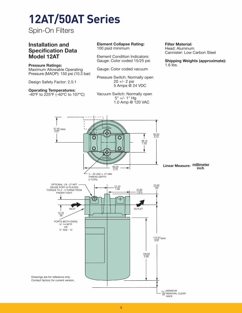
Installation andSpecifi cation DataModel 12AT
Pressure Ratings:Maximum Allowable Operating Pressure (MAOP): 150 psi (10.3 bar)
Design Safety Factor: 2.5:1
Operating Temperatures:-40ºF to 225ºF (-40ºC to 107ºC)
Element Collapse Rating:100 psid minimum
Element Condition Indicators:Gauge: Color coded 15/25 psi
Gauge: Color coded vacuum
Pressure Switch: Normally open 20 +/- 2 psi 5 Amps @ 24 VDC
Vacuum Switch: Normally open 5" +/- 1" Hg 1.0 Amp @ 120 VAC
Filter Material: Head: AluminumCannister: Low Carbon Steel
Shipping Weights (approximate):1.6 lbs.
67.822.67
MAX
95.253.75
38.101.50
95.003.74
¼ - 20 UNC x .31 MINTHREAD DEPTH2-TOTAL
47.621.875
23.62.93
172.976.81
MAX
148.845.68
12.19.48
PORTS (BOTH ENDS)¾"-14 NPTF
OR ¾" SAE - 12
MINIMUM REMOVAL CLEAR-ANCE
15.7.62
27.431.08
OPTIONAL 1/8 - 27 NPTGAUGE PORT (4 PLACES)
TORQUE TO 2 - 3 TURNS FROM FINGER TIGHT
OUTLETINLET
Linear Measure: millimeterinch
Drawings are for reference only. Contact factory for current version.
5
12AT/50AT SeriesSpin-On Filters
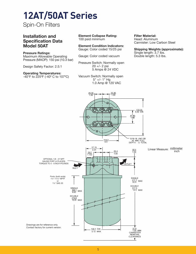
Filter Material: Head: AluminumCannister: Low Carbon Steel
Shipping Weights (approximate):Single length: 3.7 lbs.Double length: 5.3 lbs.
Element Collapse Rating:100 psid minimum
Element Condition Indicators:Gauge: Color coded 15/25 psi
Gauge: Color coded vacuum
Pressure Switch: Normally open 20 +/- 2 psi 5 Amps @ 24 VDC
Vacuum Switch: Normally open 5" +/- 1" Hg 1.0 Amp @ 120 VAC
Installation andSpecifi cation DataModel 50AT
Pressure Ratings:Maximum Allowable Operating Pressure (MAOP): 150 psi (10.3 bar)
Design Safety Factor: 2.5:1
Operating Temperatures:-40°F to 2250F (-400 C to 1070C)
Ports: (both ends)1¼"-11½" NPTF
or1¼" SAE-20
Linear Measure: millimeterinch
Drawings are for reference only. Contact factory for current version.
OPTIONAL 1/8 - 27 NPTGAUGE PORT (4 PLACES)
TORQUE TO 5 - 6 INCH POUNDS
6
12AT/50AT SeriesSpin-On Filters
0 10 20 30 40 50 60 70 80 90 100
DIF
FER
ENTI
AL
PR
ESSU
RE
(IN
H2O
)
AIR FLOW (SCFM)
12AT
0
1
2
3
4
5
6
7
8
9
10
0
1
2
3
4
5
6
7
8
9
10
0 100 200 300 400 500 600
50AT.1
.2
.3
.4
0 10 20 30 40 50 60 70 80 90 100
OIL LEVEL CHANGE RATE (GPM)
12AT
50AT
DIF
FER
ENTI
AL
PR
ESSU
RE
(PSI
)
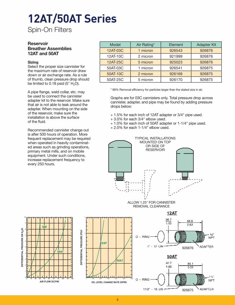
ReservoirBreather Assemblies12AT and 50AT
SizingSelect the proper size cannister for the maximum rate of reservoir draw down or air exchange rate. As a rule of thumb, clean pressure drop should be limited to 0.18 psid (5" H2O).
A pipe fl ange, weld collar, etc. may be used to connect the cannister adapter kit to the reservoir. Make sure that air is not able to leak around the adapter. When mounting on the side of the reservoir, make sure the installation is above the surface of the fl uid.
Recommended cannister change out is after 500 hours of operation. More frequent replacement may be required when operated in heavily contaminat-ed areas such as grinding operations, primary metal mills, and on mobile equipment. Under such conditions, increase replacement frequency to every 250 hours.
* 99% Removal effi ciency for particles larger than the stated size in air.
Graphs are for 03C cannisters only. Total pressure drop across cannister, adapter, and pipe may be found by adding pressure drops below:
+ 1.5% for each inch of 12AT adapter or 3/4" pipe used.+ 3.0% for each 3/4" elbow used.+ 1.0% for each inch of 50AT adapter or 1-1/4" pipe used.+ 2.0% for each 1-1/4" elbow used.
TYPICAL INSTALLATIONSMOUNTED ON TOP
OR SIDE OFRESERVOIR
ALLOW 1.25" FOR CANNISTERREMOVAL CLEARANCE
Model Air Rating* Element Adapter Kit
12AT-03C 1 micron 926543 926876
12AT-10C 2 micron 921999 926876
12AT-25C 5 micron 925023 926876
50AT-03C 1 micron 926541 926875
50AT-10C 2 micron 926169 926875
50AT-25C 5 micron 926170 926875
926876
926875
7
12AT/50AT SeriesSpin-On Filters
1/8 NPTTHREAD
1.5840.1
.369.1
1.5138.4
Linear Measure = inches mm
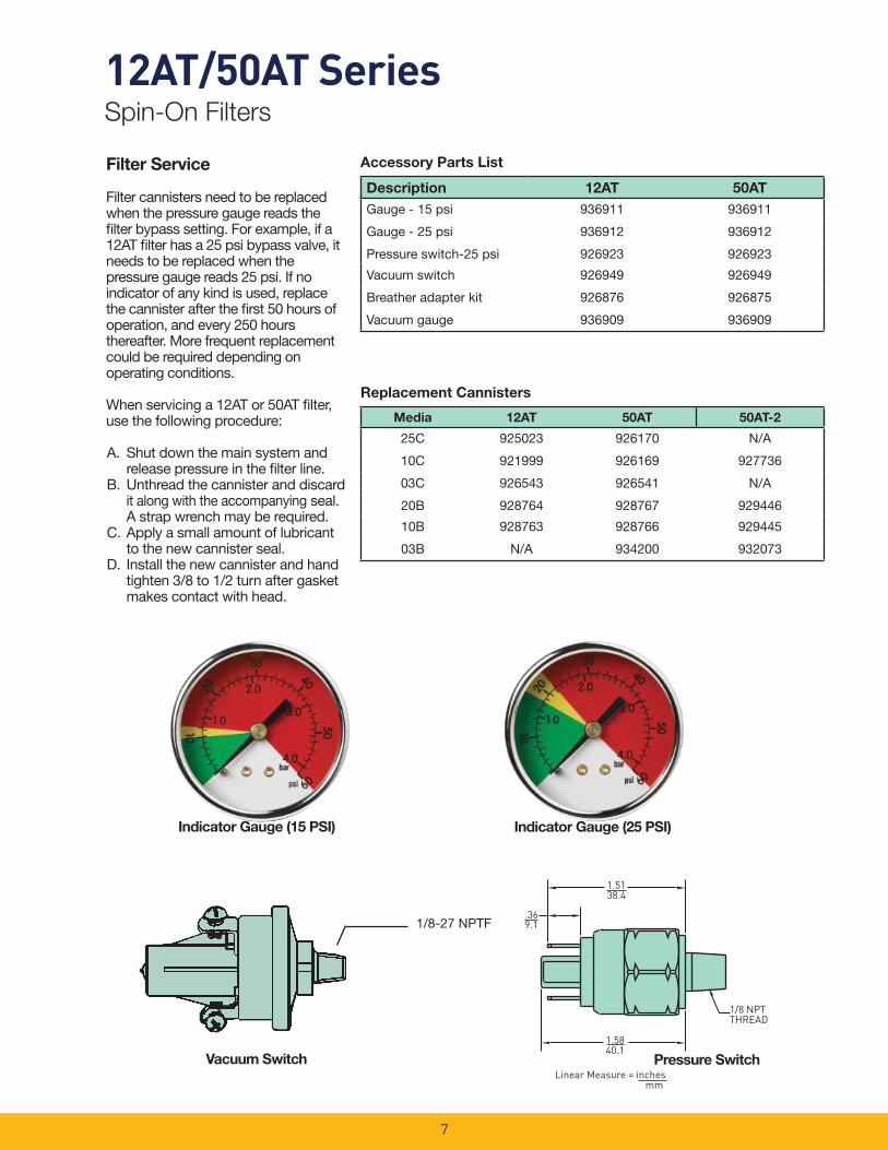
Filter Service
Filter cannisters need to be replaced when the pressure gauge reads the fi lter bypass setting. For example, if a 12AT fi lter has a 25 psi bypass valve, it needs to be replaced when the pressure gauge reads 25 psi. If no indicator of any kind is used, replace the cannister after the fi rst 50 hours of operation, and every 250 hours thereafter. More frequent replacement could be required depending on operating conditions.
When servicing a 12AT or 50AT fi lter, use the following procedure:
A. Shut down the main system and release pressure in the fi lter line.
B. Unthread the cannister and discard it along with the accompanying seal. A strap wrench may be required.
C. Apply a small amount of lubricant to the new cannister seal.
D. Install the new cannister and hand tighten 3/8 to 1/2 turn after gasket makes contact with head.
Accessory Parts List
Replacement Cannisters
1/8-27 NPTF
Description 12AT 50AT
Gauge - 15 psi 936911 936911
Gauge - 25 psi 936912 936912
Pressure switch-25 psi 926923 926923
Vacuum switch 926949 926949
Breather adapter kit 926876 926875
Vacuum gauge 936909 936909
Media 12AT 50AT 50AT-2
25C 925023 926170 N/A
10C 921999 926169 927736
03C 926543 926541 N/A
20B 928764 928767 929446
10B 928763 928766 929445
03B N/A 934200 932073
Indicator Gauge (15 PSI) Indicator Gauge (25 PSI)
Pressure SwitchVacuum Switch

8
12AT/50AT SeriesSpin-On Filters
How To OrderSelect the desired symbol (in the correct position) to construct a model code.
Example:
BOX 1 BOX 2 BOX 3 BOX 4 BOX 5 BOX 6 BOX 7 BOX 8
50AT 2 10C N 25 DD N
BOX 1: Seals Symbol Description
None Buna
BOX 2: Symbol Description
12AT Spin-on (¾" nom.)
50AT Spin-on (1¼" nom.)
BOX 3: Length Symbol Description
None Single lengthcannister
2 Double length cannister (50AT only)
BOX 4: Cannister Media Symbol Description
25C* Cellulose
10C Cellulose
03C* Cellulose
20B Microglass
10B Microglass
03B ** Microglass
BOX 5: Indicator SymbolDescription
N None
BOX 6: Bypass Setting Symbol Description
25 25 psid
15 15 psid
3 3 psid
X No bypass
BOX 7: Ports Symbol Description
12AT
BB 3/4" NPTF
MM SAE-12
50AT
DD 1-1/4" NPTF
OO SAE-20
BOX 8:Symbol Description
N None
H Inlet and outlet, both
sides (all ports drilled and
tapped)
* Not available in 50AT-2** Not available in 12AT
NOTE: Gauges must be ordered separately.
Please note the bolded options refl ect standard options with a reduced lead-time. Consult factory on all other lead-time options.
Basic Assembly
Gauge Port Location

PT SeriesTank Top Filters
9

10
PT SeriesApplications
The new PT series fi lter is available in two diameters and three lengths for fl ow ranges from 5-50 gpm. The PT2 and PT4 fi lter cartridges utilize Microglass media in 2, 5, 10 and 20 microns for the industry’s best particle removal effi ciency and retention.
This unique design simply threads into a ported weld ring or fl ange, which can be bolted to a metal reservoir.
The disposable fi lter cartridge is a single-piece construction, which incorporates the nylon cover and integral 25 psi bypass valve. The fl ow path is inside-out and requires no special tools for service.
This concept assures minimal installation costs with the least space requirements for return line applications.
The PT Series fi lter combines high effi ciency Microglass fi ltration with low cost installation featured in a new patented element design.
Together we can…
Preserve the environment. Minimize waste and promote energy effi ciency.
Achieve worldwide fi ltration solutions. Build global confi dence.
Redefi ne new limits. Forge ahead with advanced technology.
Keep contamination under control. Reduce maintenance costs.
Enhance total system reliability. Focus on customer satisfaction.
Reach optimum potential. Drill to greater depths.
…engineer your success.
Typical Applications
• Turf Maintenance
• Material Handling
• Aerial Lifts
• Fan Drive

11
PT SeriesFeatures
1 Easy element assembly removal
2 Unique high fl ow top end cap
3 Lightweight cast aluminum head
4 Patented fi lter element assembly
5 Bowl-less, inside-out fl ow
Downstream element support with “no aeration” design
Solid bottom endcap with integrated bypass valve
Low profi le tank top design
2
3
4
6
5
7
8
8
4
2
1
5
7
6
3

12
PT Series
Patented Filter Element
Premium original equipment performance every time
Bottom Endcap Integrated
Bypass Valve
New bypass valve with every element change
Insures reliable performanceInsures reliable performance
No system contamination during element servicing
Inside-Out Element
Flow Path
Contamination contained within the element
No system contamination during element servicing
No system aeration
No Aeration Design
Oil cascades down theperforated outer support core
performance every time
Bottom Endcap Integrated
Bypass Valve
New bypass valve with every
Significant cost savings over filters with bowls
Tank Top, Bowl-Less Design
Reduces weight
Lower maintenance costs
High Flow, Low Pressure
Drop Top Endcap Design
Long element life
Less maintenance and downtime
Premium Microglass
Media
Superior dirt holdingcapacity and efficiency
13
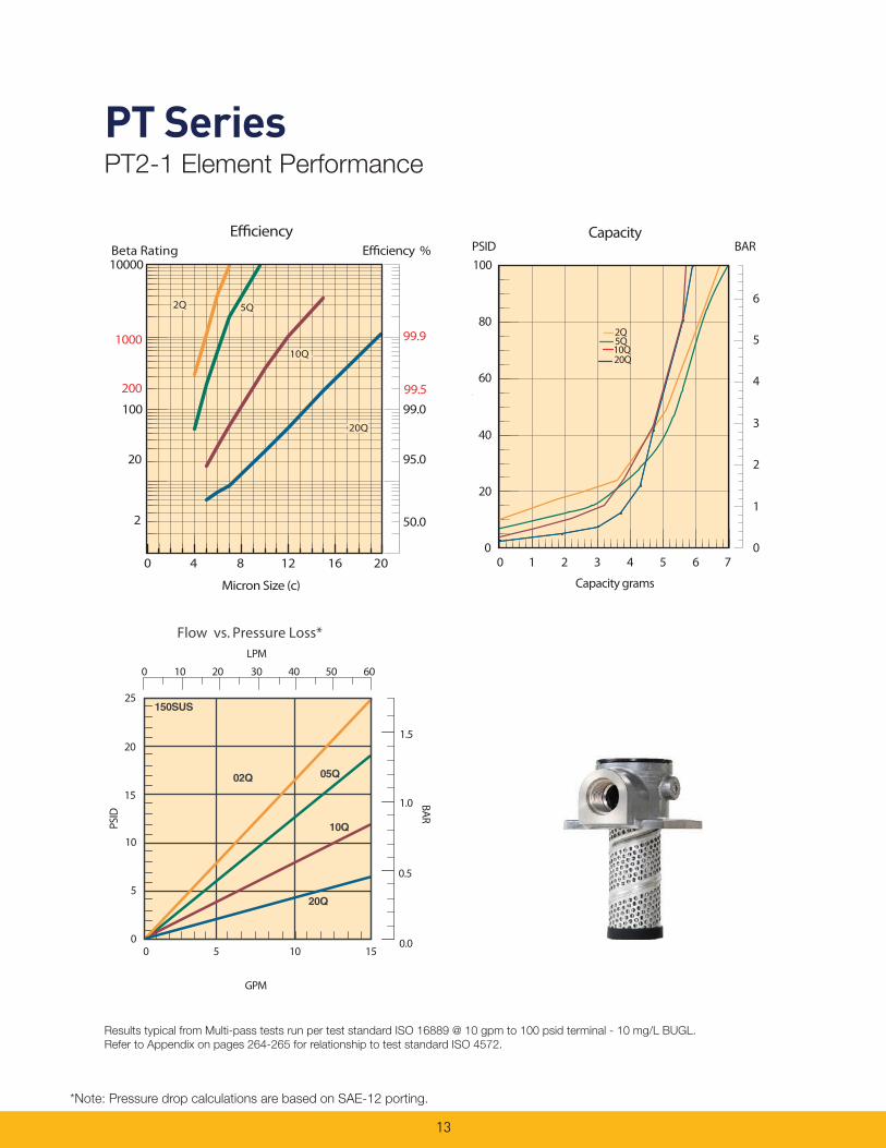
PT SeriesPT2-1 Element Performance
Results typical from Multi-pass tests run per test standard ISO 16889 @ 10 gpm to 100 psid terminal - 10 mg/L BUGL.
Refer to Appendix on pages 264-265 for relationship to test standard ISO 4572.
*Note: Pressure drop calculations are based on SAE-12 porting.
Efficiency %Efficiency
Beta Rating
1000
10000
99.9
99.599.0100
200
20
2 50.0
95.0
Micron Size (c)
2Q
10Q
20Q
5Q
0 4 8 12 16 20
Flow vs. Pressure Loss*
25
20
15
10
5
0
1.5
1.0
0.5
0.00 5 10 15
GPM
LPM
0 10 20 30 40 50 60
PSID
BAR
PSID BARCapacity
20Q10Q5Q2Q
0
1
2
3
4
5
6
0
20
40
60
80
100
s
0 1 2 3 4 5 6 7
Capacity grams
14
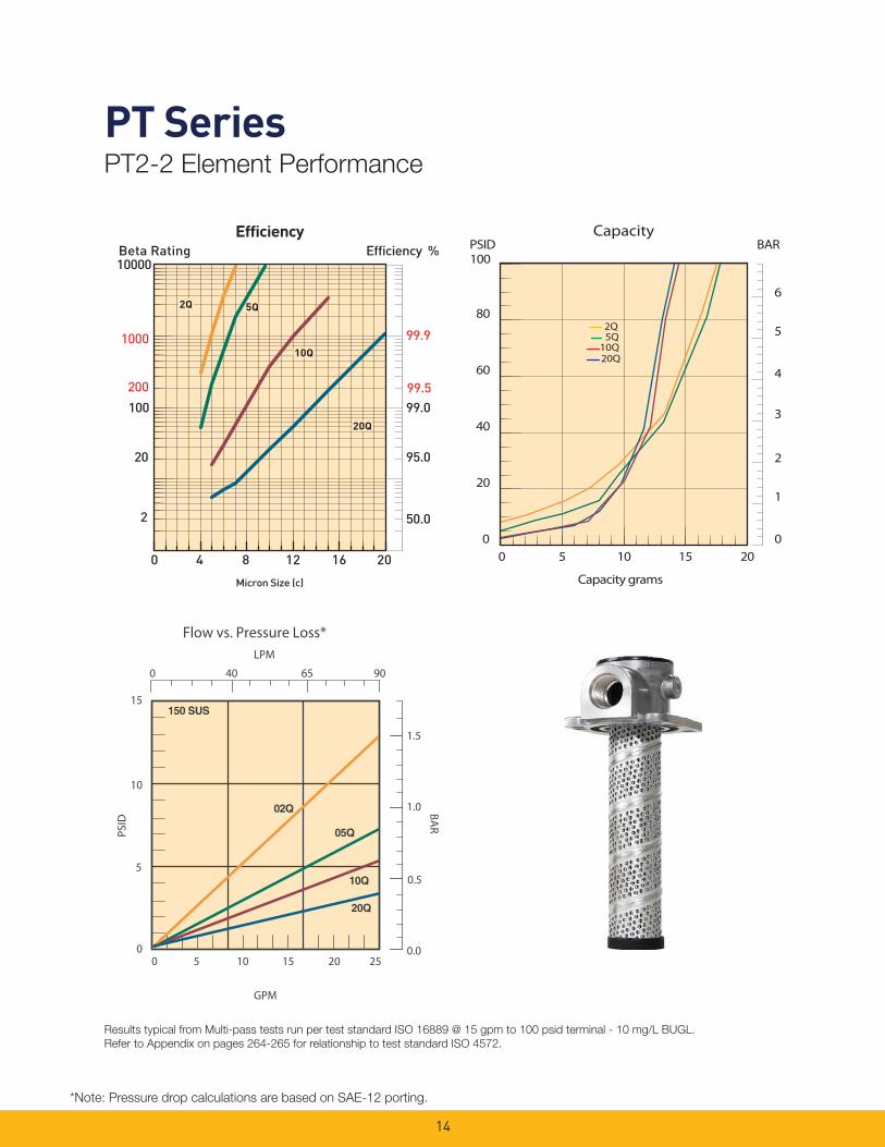
PT SeriesPT2-2 Element Performance
Results typical from Multi-pass tests run per test standard ISO 16889 @ 15 gpm to 100 psid terminal - 10 mg/L BUGL.
Refer to Appendix on pages 264-265 for relationship to test standard ISO 4572.
*Note: Pressure drop calculations are based on SAE-12 porting.
PSID BARCapacity
20Q
2Q5Q
10Q
0
1
2
3
4
5
6
0
20
40
60
80
100
0 5 10 15 20
Capacity grams
LPM
PSID
BAR
GPM
0 5 10 15 20 250
5
10
15
0.0
0.5
1.0
1.5
0 40 65 90
Flow vs. Pressure Loss*

15
PT SeriesPT4-1 Element Performance
Results typical from Multi-pass tests run per test standard ISO 16889 @ 15 gpm to 100 psid terminal - 10 mg/L BUGL.
Refer to Appendix on pages 264-265 for relationship to test standard ISO 4572.
*Note: Pressure drop calculations are based on SAE-16 porting.
BARPSIDCapacity
0
1
2
3
4
5
6
0
20
40
60
80
100
0 10 20 30 40Capacity grams
2Q5Q
10Q20Q
PSI
D B
AR
GPM
25
20
15
10
5
0
1.5
1.0
0.5
0.0
0 50 100 150 200
Flow vs. Pressure Loss*LPM
0 10 20 30 40 50

16
PT SeriesPT4-2 Element Performance
Results typical from Multi-pass tests run per test standard ISO 16889 @ 30 gpm to 100 psid terminal - 10 mg/L BUGL.
Refer to Appendix on pages 264-265 for relationship to test standard ISO 4572.
*Note: Pressure drop calculations are based on SAE-16 porting.
BARPSIDCapacity
0
1
2
3
4
5
6
0
20
40
60
80
100
0 10 20 30 40 50 60 70
Capacity grams
2Q
10Q20Q
5Q
0
5
10
15
0 10 20 30 40 50
1.0
0.5
0.0
PSI
D B
AR
LPM
0 40 75 110 150 190
Flow vs. Pressure Loss*
GPM

17
PT SeriesPT4-3 Element Performance
Results typical from Multi-pass tests run per test standard ISO 16889 @ 45 gpm to 100 psid terminal - 10 mg/L BUGL.
Refer to Appendix on pages 264-265 for relationship to test standard ISO 4572.
*Note: Pressure drop calculations are based on SAE-16 porting.
BARPSIDCapacity
2Q
10Q20Q
5Q
0
1
2
3
4
5
6
0
20
40
60
80
100
0 20 40 60 80 100 120
Capacity grams
LPM
Flow vs. Pressure Loss*
0 40 75 110 150 190
0.5
0.0
1.0
PSI
D B
AR
15
10
5
0 0 10 20 30 40 50
GPM
18
Drawings are for reference only. Contact factory for current version.
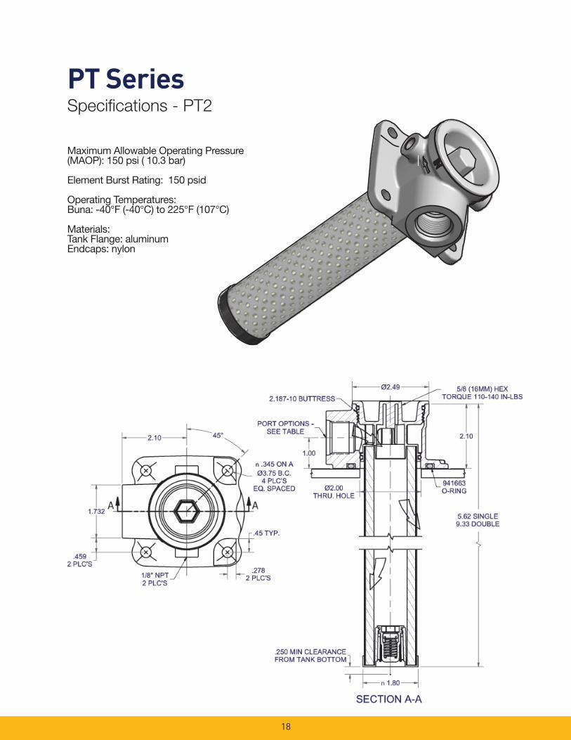
PT SeriesSpecifi cations - PT2
Maximum Allowable Operating Pressure (MAOP): 150 psi ( 10.3 bar)
Element Burst Rating: 150 psid
Operating Temperatures:Buna: -40°F (-40°C) to 225°F (107°C)
Materials:Tank Flange: aluminumEndcaps: nylon

19
Drawings are for reference only. Contact factory for current version.
PT SeriesSpecifi cations - PT4
SECTION A-A
A A
4.06Ø
1/8-27 PTF2 PLC'S
REF.
3.500-10 BUTTRESS
14.55`.060
6.20± .060 SINGLE9.79± .060 DOUBLE
TRIPLE
2.41
1.11
3.09Ø
2.70
.400 MIN CLEARANCEFROM TANK BOTTOM
PORT OPTIONS -SEE TABLE
2.045
36°
n.345 ON A Ø5.50 B.C.
5 PLC'SEQ. SPACED
1/8-27 PTF2 PLC'S
.90 DIA FLAT5 PLC'S
15/16 (24MM) HEXTORQUE 200-240 IN-LBS 3.33Ø
THRU. HOLE
941664O-RING
Maximum Allowable Operating Pressure (MAOP): 150 psi ( 10.3 bar)
Element Burst Rating: 150 psid
Operating Temperatures:Buna: -40°F (-40°C) to 225°F (107°C)
Materials:Tank Flange: aluminumEndcaps: nylon
20
1.5138.4
1.5840.1
.369.1
1/8 NPTTHREAD
inchesmm
Linear measure =
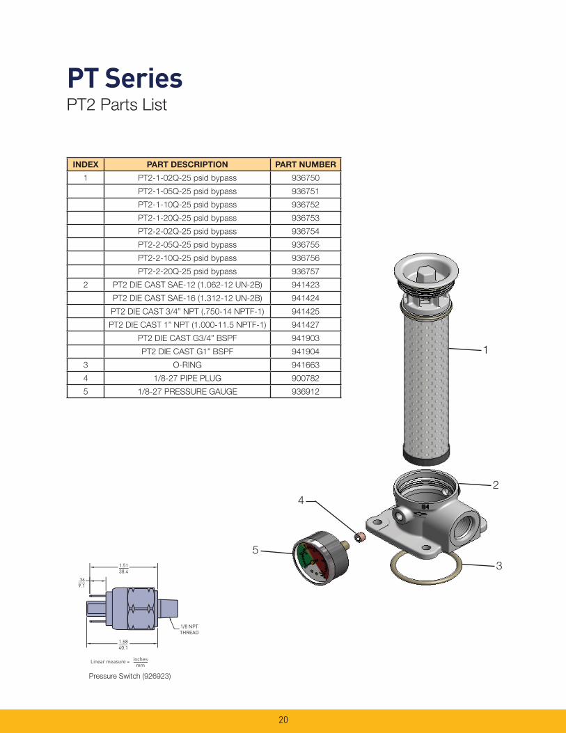
INDEX PART DESCRIPTION PART NUMBER
1 PT2-1-02Q-25 psid bypass 936750
PT2-1-05Q-25 psid bypass 936751
PT2-1-10Q-25 psid bypass 936752
PT2-1-20Q-25 psid bypass 936753
PT2-2-02Q-25 psid bypass 936754
PT2-2-05Q-25 psid bypass 936755
PT2-2-10Q-25 psid bypass 936756
PT2-2-20Q-25 psid bypass 936757
2 PT2 DIE CAST SAE-12 (1.062-12 UN-2B) 941423
PT2 DIE CAST SAE-16 (1.312-12 UN-2B) 941424
PT2 DIE CAST 3/4” NPT (.750-14 NPTF-1) 941425
PT2 DIE CAST 1” NPT (1.000-11.5 NPTF-1) 941427
PT2 DIE CAST G3/4” BSPF 941903
PT2 DIE CAST G1” BSPF 941904
3 O-RING 941663
4 1/8-27 PIPE PLUG 900782
5 1/8-27 PRESSURE GAUGE 936912
1
2
3
5
4
PT SeriesPT2 Parts List
Pressure Switch (926923)

21
PT SeriesPT4 Parts List
INDEX PART DESCRIPTION PART NUMBER
1 PT4-1-02Q-25 psid bypass 936742
PT4-1-05Q-25 psid bypass 936743
PT4-1-10Q-25 psid bypass 936744
PT4-1-20Q-25 psid bypass 936745
PT4-2-02Q-25 psid bypass 936746
PT4-2-05Q-25 psid bypass 936747
PT4-2-10Q-25 psid bypass 936748
PT4-2-20Q-25 psid bypass 936749
PT4-3-02Q-25 psid bypass 936876
PT4-3-05Q-25 psid bypass 936877
PT4-3-10Q-25 psid bypass 936878
PT4-3-20Q-25 psid bypass 936879
2 PT4 DIE CAST SAE-16 (1.312-12 UN-2B) 941417
PT4 DIE CAST SAE-20 (1.625-12 UN-2B) 941448
PT4 DIE CAST 1” NPT (1.000-11.5 NPTF-1) 941449
PT4 DIE CAST 1 1/4” NPT (1.250-11.5 NPTF-1) 941450
PT4 DIE CAST G1” BSPF 941905
PT4 DIE CAST G1 1/4” BSPF 941906
3 O-RING 941664
4 1/8-27 PIPE PLUG 900782
5 1/8-27 PRESSURE GAUGE 936912
1
2
3
4
5
1.5138.4
1.5840.1
.369.1
1/8 NPTTHREAD
inchesmm
Linear measure =
Pressure Switch (926923)
22
Global products as identifi ed are offered worldwide through all Parker locations and utilize a common ordering code.
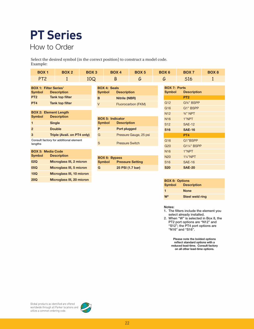
PT SeriesHow to Order
Select the desired symbol (in the correct position) to construct a model code. Example:
BOX 1 BOX 2 BOX 3 BOX 4 BOX 5 BOX 6 BOX 7 BOX 8
PT2 1 10Q B G G S16 1
BOX 1: Filter Series1
Symbol Description
PT2 Tank top fi lter
PT4 Tank top fi lter
BOX 5: Indicator
Symbol Description
P Port plugged
G Pressure Gauge, 25 psi
S Pressure Switch
BOX 4: Seals
Symbol Description
B Nitrile (NBR)
V Fluorocarbon (FKM)
BOX 8: Options
Symbol Description
1 None
W2 Steel weld ring
BOX 3: Media Code
Symbol Description
02Q Microglass III, 2 micron
05Q Microglass III, 5 micron
10Q Microglass III, 10 micron
20Q Microglass III, 20 micron
Please note the bolded options
refl ect standard options with a
reduced lead-time. Consult factory
on all other lead-time options.
BOX 6: Bypass
Symbol Pressure Setting
G 25 PSI (1.7 bar)
BOX 2: Element Length
Symbol Description
1 Single
2 Double
3 Triple (Avail. on PT4 only)
BOX 7: Ports
Symbol Description
PT2
G12 G¾ ” BSPP
G16 G1” BSPP
N12 ¾ ” NPT
N16 1”NPT
S12 SAE-12
S16 SAE-16
PT4
G16 G1”BSPP
G20 G1¼ ” BSPP
N16 1”NPT
N20 1¼ ”NPT
S16 SAE-16
S20 SAE-20
Notes:
1. The fi lters include the element you select already installed.
2. When “W” is selected in Box 8, the PT2 port options are “N12” and “S12”; the PT4 port options are “N16” and “S16”.
Consult factory for additional element lengths

KLT and KLS SeriesTank Top Return Line Filters
23

24
KLT/KLS SeriesTank Top Return Line Filters
Parker’s new KLS /KLT Tank Top Return Line Filters are ideally suited for Mobile and Industrial high to medium fl ow return applications, from 30 to 120 GPM. This cost-effective, in-tank fi lter series provides maximum fl ow and dirt holding capacity for longer fi lter element life in a simple, easy-to-install-and-service assembly.
The generous element size with extensive media area ensures continuous fi ltration during cold start up conditions. The inside-to-out fl ow path with closed bottom provides additional assurance that all contaminants remain captured during element service removal. The fi lters have a pressure rating of 150 psi static, a temperature range of -40˚F to 225˚F, and are available in a wide range of high-effi ciency Microglass III media in 2, 5, 10 and 20 micron for all system cleanliness requirements. Bypass valves are built into the element to ensure further performance integrity. A new bypass is provided with each element change. This rugged design meets the needs for the demanding applications in mobile off -highway and on-highway applications for construction equipment, logging, refuse vehicles, mining, oil and gas recovery, marine, and industrial power units.
Feature Advantage Benefi t
• Tank top mounted fi lter • Saves space and reduces mounting hardware
• Lower cost, easy to integrate• KLS model directly retrofi ts
competitive housing
• Two-piece head and element construction perforated with metal outer wrap
• No bowl required• Provides excellent fl ow diffusing,
eliminating aeration
• Reduced cost and assembly weight
• Improved performance
• High effi ciency Microglass media maximizing fi ltration area
• Combines high particle capture effi ciency with high dirt holding capacity and lower �P
• Cleaner fl uids, longer lasting with fewer service intervals
• Continuous fi ltration for cold start ups
• Lower operating costs
• Element design includes intergral disposable bypass valve with closed bottom end cap
• New bypass with each element change
• Ensures captured contaminants are removed with each element change
• Ensures reliable bypass performance
• No leakage• Cleaner fl uids reduce risk for
contamination during service
• Magnetic prefi ltration • Removes large ferrous contaminants
• Extends element life• Visual indication of component
wear
• Fill and gauge ports • Add fl uid through high performance fi lter media
• Gauge ports allow for added instrumentation
• Initial fl uid integrity extends system component life
• Monitor element life
Applications for KLT and KLS Filters
• Mobile Equipment
• Construction, Refuse
• Industrial Power Units
• Machine Tool
• Oil Field
25
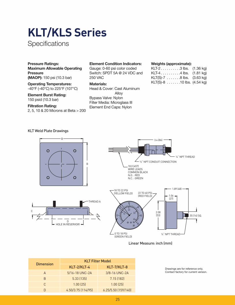
KLT/KLS SeriesSpecifi cations
Pressure Ratings: Maximum Allowable Operating
Pressure
(MAOP): 150 psi (10.3 bar)
Operating Temperatures:
-40°F (-40°C) to 225°F (107°C)
Element Burst Rating:
150 psid (10.3 bar)
Filtration Rating:
2, 5, 10 & 20 Microns at Beta > 200
Linear Measure: inch (mm)
KLT Weld Plate Drawings
3.4 (86)
¼“ NPT THREAD
½“ NPT CONDUIT CONNECTION
18.0 (457)WIRE LEADSCOMMON BLACKN.O. : REDN.C. : GREEN
18 TO 22 PSI(YELLOW FIELD)
1.89 (48)22 TO 60 PSI(RED FIELD) 1.06
(27)
2.08(53) .55 (14) SQ.
¼“ NPT THREAD0 TO 18 PSI(GREEN FIELD)
DHOLE IN RESERVOIR
C
THREAD A
B
B
DimensionKLT Filter Model
KLT-2/KLT-4 KLT-7/KLT-8
A 5/16-18 UNC-2A 3/8-16 UNC-2A
B 5.33 (135) 7.15 (182)
C 1.00 (25) 1.00 (25)
D 4.50/3.75 (114/95) 6.25/5.50 (159/140)
Element Condition Indicators:
Gauge: 0-60 psi color codedSwitch: SPDT 5A @ 24 VDC and 250 VAC
Materials:
Head & Cover: Cast Aluminum AlloyBypass Valve: NylonFilter Media: Microglass IIIElement End Caps: Nylon
Weights (approximate):
KLT-2 . . . . . . . . . .3 lbs. (1.36 kg)KLT-4 . . . . . . . . . .4 lbs. (1.81 kg)KLT(S)-7 . . . . . . .8 lbs. (3.63 kg)KLT(S)-8 . . . . . . .10 lbs. (4.54 kg)
Drawings are for reference only. Contact factory for current version.

26
KLT Series Dimensional Drawings
KLT 2 / KLT 4 KLT 7 / KLT 8
3.54 (90)
TORQUE: 7 FT-LB (10 N-m)
6.54 (166)TYP.
SAE-24 STRAIGHT THREADO-RING PORT
.43 (11) DIA. MOUNTING HOLES(4 PLACES) ON 6.89 (175) B.C.RECOMMENDED HEAD TO TANKTORQUE: 30 FT-LB (40 N-m)
CMIN. SERVICE CLEARANCE ¼ NPT PLUGGED GAUGE PORT(S)
(3 PLACES)
1.42 (36)
3.66 (93)
DRESERVOIR
CUTOUTDIAMETER
L
1.10 (28)
L
D
RESERVOIRCUTOUT
DIAMETER
¼ NPT PLUGGEDGAUGE PORT(S)(3 PLACES)
2.83 (72)
C
MIN. SERVICECLEARANCE
.35 (9) DIA. MOUNTING HOLES(4 PLACES) ON 4.96 (126) B.C.RECOMMENDED HEAD TO TANKTORQUE: 11 FT-LB (15 N-m)
SAE-16 STRAIGHTTHREAD O-RING PORT
TORQUE: 3 FT-LB (4 N-m)
2.68 (68)
4.72 (120)TYP
Linear Measure: inch (mm)
DimensionsKLT Filter Model
KLT-2 KLT-4
C 5.75 (146) 9.50 (241)
L 4.16 (106) 7.75 (197)
D3.6 (93)
3.56 (90)
DimensionsKLT Filter Model
KLT-7 KLT-8
C 13.00 (330) 19.25 (489)
L 11.46 (291) 17.70 (450)
D5.36 (136)
5.26 (133)
Drawings are for reference only. Contact factory for current version.

KLT Series Dimensional Drawings
27
TORQUE: 12 FT-LB (16 N-m)
3.38 (86).43 (11) DIA. MOUNTING HOLES(4 PLACES) ON 6.25 (158.8) B.C.RECOMMENDED HEAD TOTANK TORQUE: 30 FT-LB (40 N-m)
6.76 (172)
CMIN. SERVICECLEARANCE
SAE-24 STRAIGHT THREADO-RING PORTS (BOTH SIDES)
3.62 (92)
1.62 (41)
DRESERVOIR
CUTOUTDIAMETER
¼ NPTPLUGGEDGAUGE PORTS(2 PLACES)
L
KLS 7 / KLS 8
Linear Measure: inch (mm)
DimensionsKLS Filter Model
KLS-7 KLS-8
C 13.00 (330) 19.25 (489)
L 11.46 (291) 17.70 (450)
D5.00 (127)
4.80 (122)
Drawings are for reference only. Contact factory for current version.
28
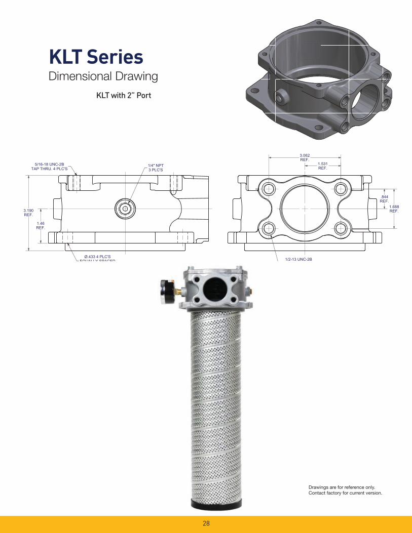
KLT SeriesDimensional Drawing
KLT with 2” Port
3.190REF.
1.46REF.
1/2-13 UNC-2B
1/4" NPT3 PLC'S
5/16-18 UNC-2BTAP THRU. 4 PLC'S
3.062REF.
1.531REF.
1.688REF.
.844REF.
Ø.433 4 PLC'SEQUALLY SPACED
Drawings are for reference only. Contact factory for current version.
29
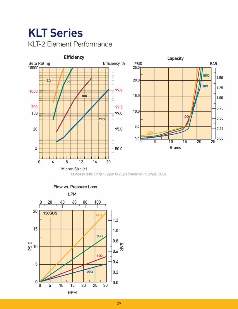
KLT Series KLT-2 Element Performance
Efficiency %Efficiency
Beta Rating
1000
10000
99.9
99.599.0100
200
20
2 50.0
95.0
Micron Size (c)
2Q
10Q
20Q
2Q
10Q
20Q
2Q
10Q
20Q
5Q5Q
0 4 8 12 16 20
Flow vs. Pressure Loss
Multipass tests run @ 15 gpm to 25 psid terminal - 10 mg/L BUGL

30
KLT SeriesKLT-4 Element Performance
Flow vs. Pressure Loss
Efficiency %Efficiency
Beta Rating
1000
10000
99.9
99.599.0100
200
20
2 50.0
95.0
Micron Size (c)
2Q
10Q
20Q
2Q
10Q
20Q
2Q
10Q
20Q
5Q5Q
0 4 8 12 16 20
Multipass tests run @ 30 gpm to 25 psid terminal - 10 mg/L BUGL
31
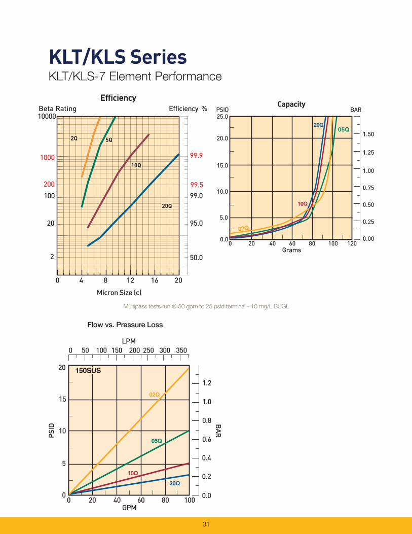
KLT/KLS Series KLT/KLS-7 Element Performance
Flow vs. Pressure Loss
Efficiency %Efficiency
Beta Rating
1000
10000
99.9
99.599.0100
200
20
2 50.0
95.0
Micron Size (c)
2Q
10Q
20Q
2Q
10Q
20Q
2Q
10Q
20Q
5Q5Q
0 4 8 12 16 20
Multipass tests run @ 50 gpm to 25 psid terminal - 10 mg/L BUGL
32
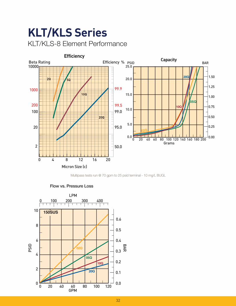
KLT/KLS SeriesKLT/KLS-8 Element Performance
Flow vs. Pressure Loss
Efficiency %Efficiency
Beta Rating
1000
10000
99.9
99.599.0100
200
20
2 50.0
95.0
Micron Size (c)
2Q
10Q
20Q
2Q
10Q
20Q
2Q
10Q
20Q
5Q5Q
0 4 8 12 16 20
Multipass tests run @ 70 gpm to 25 psid terminal - 10 mg/L BUGL
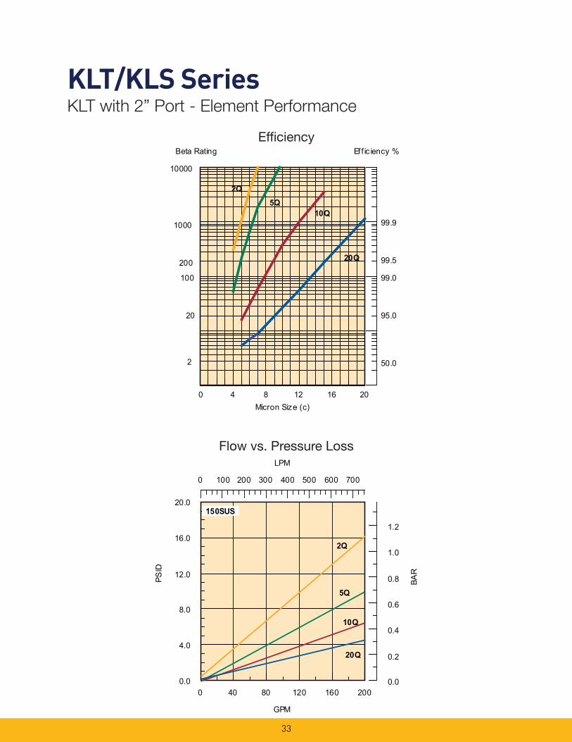
KLT/KLS Series KLT with 2” Port - Element Performance
Eff ic iency %Beta Rating
1000
10000
99.9
99.5
100
200
20
2 50.0
95.0
99.0
10Q
2Q5Q
20Q
0 4 8 12 16 20Micron Size (c)
Effi ciency
Flow vs. Pressure Loss
0 100 200 300 400
LPM
500 600 700
0.0
4.0
8.0
12.0
16.0
20.0
PSID
0.0
0.2
0.4
0.6
0.8 BAR
1.0
1.2
0 40 80 120 160 200
GPM
2Q
5Q
10Q
20Q
150SUS
33
34
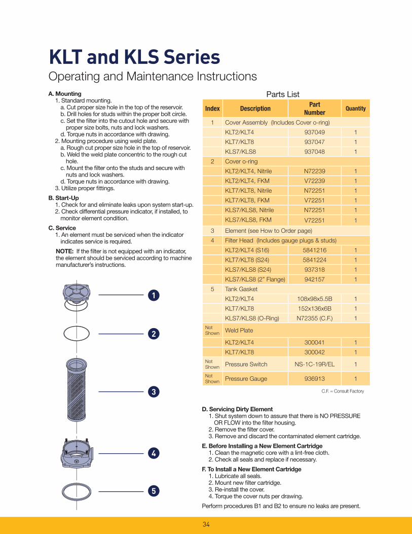
KLT and KLS SeriesOperating and Maintenance Instructions
Parts List
1
3
2
4
5
A. Mounting 1. Standard mounting.
a. Cut proper size hole in the top of the reservoir. b. Drill holes for studs within the proper bolt circle. c. Set the fi lter into the cutout hole and secure with
proper size bolts, nuts and lock washers. d. Torque nuts in accordance with drawing.
2. Mounting procedure using weld plate. a. Rough cut proper size hole in the top of reservoir. b. Weld the weld plate concentric to the rough cut
hole. c. Mount the fi lter onto the studs and secure with
nuts and lock washers. d. Torque nuts in accordance with drawing.
3. Utilize proper fi ttings.
B. Start-Up 1. Check for and eliminate leaks upon system start-up. 2. Check differential pressure indicator, if installed, to
monitor element condition.
C. Service 1. An element must be serviced when the indicator
indicates service is required.
NOTE: If the fi lter is not equipped with an indicator, the element should be serviced according to machine manufacturer’s instructions.
D. Servicing Dirty Element 1. Shut system down to assure that there is NO PRESSURE
OR FLOW into the fi lter housing. 2. Remove the fi lter cover. 3. Remove and discard the contaminated element cartridge.
E. Before Installing a New Element Cartridge 1. Clean the magnetic core with a lint-free cloth. 2. Check all seals and replace if necessary.
F. To Install a New Element Cartridge 1. Lubricate all seals. 2. Mount new fi lter cartridge. 3. Re-install the cover. 4. Torque the cover nuts per drawing.
Perform procedures B1 and B2 to ensure no leaks are present.
C.F. = Consult Factory
Index DescriptionPart
NumberQuantity
1 Cover Assembly (Includes Cover o-ring)
KLT2/KLT4 937049 1
KLT7/KLT8 937047 1
KLS7/KLS8 937048 1
2 Cover o-ring
KLT2/KLT4, Nitrile N72239 1
KLT2/KLT4, FKM V72239 1
KLT7/KLT8, Nitrile N72251 1
KLT7/KLT8, FKM V72251 1
KLS7/KLS8, Nitrile N72251 1
KLS7/KLS8, FKM V72251 1
3 Element (see How to Order page)
4 Filter Head (Includes gauge plugs & studs)
KLT2/KLT4 (S16) 5841216 1
KLT7/KLT8 (S24) 5841224 1
KLS7/KLS8 (S24) 937318 1
KLS7/KLS8 (2” Flange) 942157 1
5 Tank Gasket
KLT2/KLT4 108x98x5.5B 1
KLT7/KLT8 152x136x6B 1
KLS7/KLS8 (O-Ring) N72355 (C.F.) 1
Not
ShownWeld Plate
KLT2/KLT4 300041 1
KLT7/KLT8 300042 1
Not
ShownPressure Switch NS-1C-19R/EL 1
Not
ShownPressure Gauge 936913 1
35
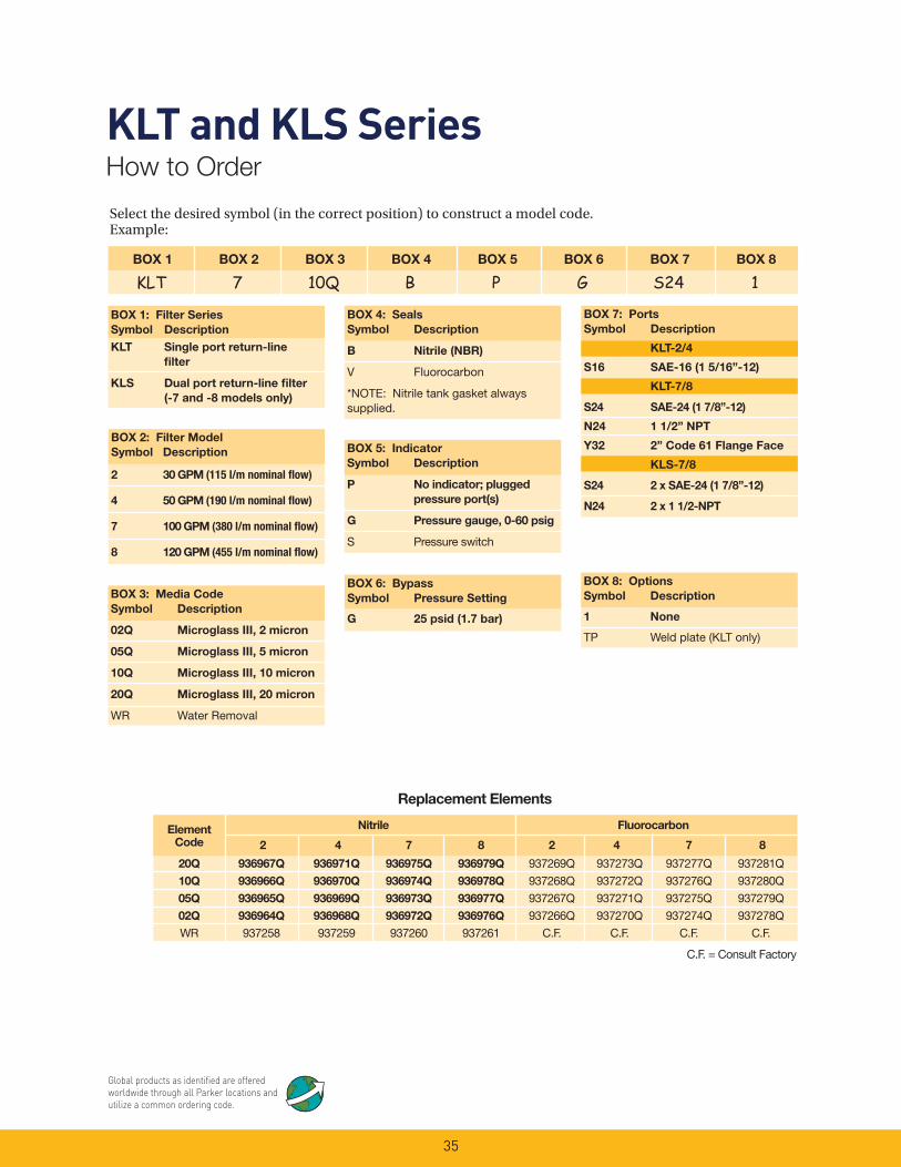
Select the desired symbol (in the correct position) to construct a model code. Example:
BOX 1 BOX 2 BOX 3 BOX 4 BOX 5 BOX 6 BOX 7 BOX 8
KLT 7 10Q B P G S24 1
BOX 1: Filter Series
Symbol Description
KLT Single port return-line
fi lter
KLS Dual port return-line fi lter
(-7 and -8 models only)
BOX 5: Indicator
Symbol Description
P No indicator; plugged
pressure port(s)
G Pressure gauge, 0-60 psig
S Pressure switch
BOX 4: Seals
Symbol Description
B Nitrile (NBR)
V Fluorocarbon
*NOTE: Nitrile tank gasket always supplied.
BOX 8: Options
Symbol Description
1 None
TP Weld plate (KLT only)
BOX 2: Filter Model
Symbol Description
2 30 GPM (115 l/m nominal fl ow)
4 50 GPM (190 l/m nominal fl ow)
7 100 GPM (380 l/m nominal fl ow)
8 120 GPM (455 l/m nominal fl ow)
BOX 3: Media Code
Symbol Description
02Q Microglass III, 2 micron
05Q Microglass III, 5 micron
10Q Microglass III, 10 micron
20Q Microglass III, 20 micron
WR Water Removal
BOX 6: Bypass
Symbol Pressure Setting
G 25 psid (1.7 bar)
KLT and KLS SeriesHow to Order
Global products as identifi ed are offered worldwide through all Parker locations and utilize a common ordering code.
Replacement Elements
Element Nitrile Fluorocarbon
Code 2 4 7 8 2 4 7 8
20Q 936967Q 936971Q 936975Q 936979Q 937269Q 937273Q 937277Q 937281Q
10Q 936966Q 936970Q 936974Q 936978Q 937268Q 937272Q 937276Q 937280Q
05Q 936965Q 936969Q 936973Q 936977Q 937267Q 937271Q 937275Q 937279Q
02Q 936964Q 936968Q 936972Q 936976Q 937266Q 937270Q 937274Q 937278Q
WR 937258 937259 937260 937261 C.F. C.F. C.F. C.F.
C.F. = Consult Factory
BOX 7: Ports
Symbol Description
KLT-2/4
S16 SAE-16 (1 5/16”-12)
KLT-7/8
S24 SAE-24 (1 7/8”-12)
N24 1 1/2” NPT
Y32 2” Code 61 Flange Face
KLS-7/8
S24 2 x SAE-24 (1 7/8”-12)
N24 2 x 1 1/2-NPT
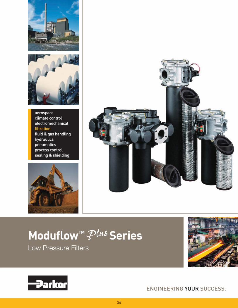
Modufl ow™ SeriesLow Pressure Filters
36
37
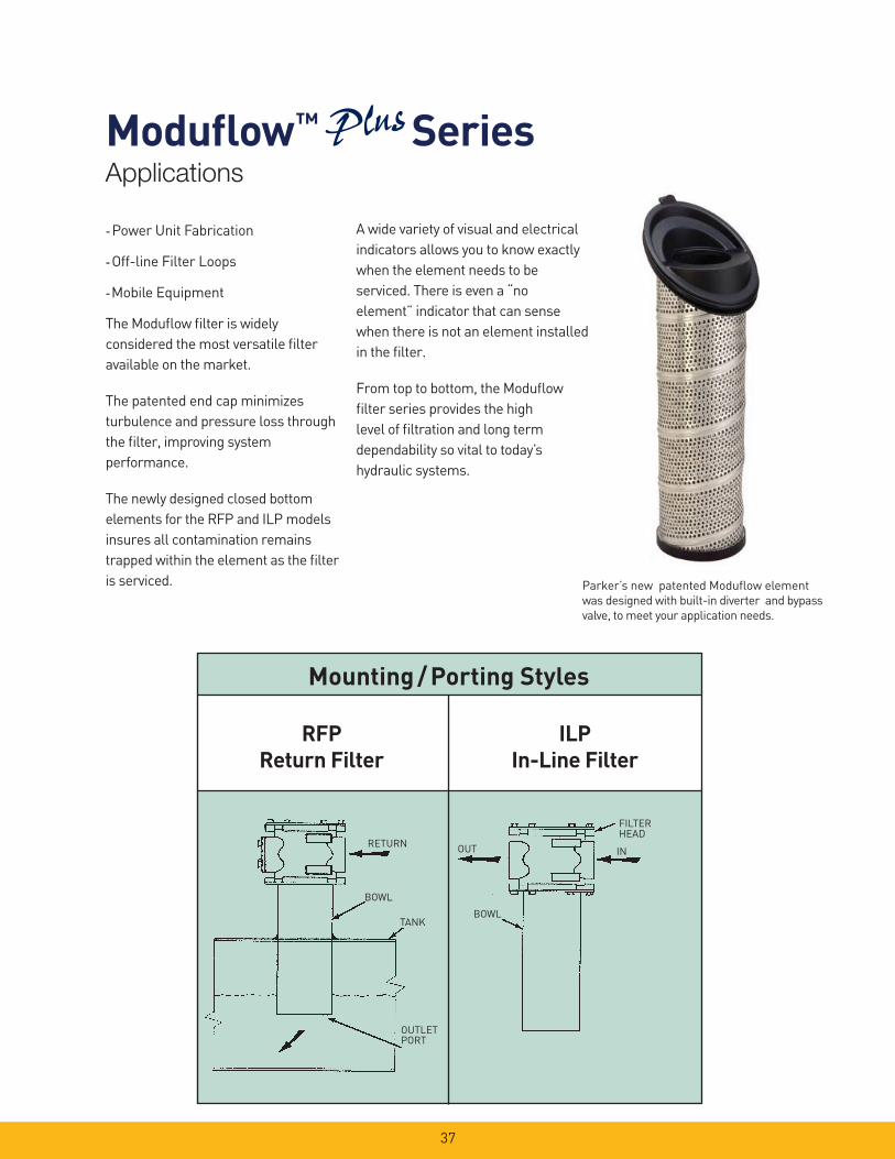
- Power Unit Fabrication
- Off-line Filter Loops
- Mobile Equipment
The Modufl ow fi lter is widely
considered the most versatile fi lter
available on the market.
The patented end cap minimizes
turbulence and pressure loss through
the fi lter, improving system
performance.
The newly designed closed bottom
elements for the RFP and ILP models
insures all contamination remains
trapped within the element as the fi lter
is serviced.
Mounting / Porting Styles
RFPReturn Filter
ILPIn-Line Filter
IN
BOWL
OUT
FILTERHEAD
RETURN
BOWL
TANK
OUTLETPORT
A wide variety of visual and electrical
indicators allows you to know exactly
when the element needs to be
serviced. There is even a “no
element” indicator that can sense
when there is not an element installed
in the fi lter.
From top to bottom, the Modufl ow
fi lter series provides the high
level of fi ltration and long term
dependability so vital to today’s
hydraulic systems.
Parker’s new patented Modufl ow element
was designed with built-in diverter and bypass
valve, to meet your application needs.
Applications
Modufl ow™ Series

38
Modufl ow™ SeriesFeatures
Flanges- NPT or
SAE ¾” to 2”
- Lightweight aluminum
Bypass (not visible)- Integral 35 psi bypass replaced
with every element change
Indicators- Visual or electrical
- Mounted on either side
- Standard “no element” indication
Cover- Slotted for quick
release
- Lightweight aluminum
Bowl- Single or double
length
- Durable steel construction
Element(not visible)- Available in high performance
Microglass III media
- Single or double length
Feature Advantage Benefi t
��Top access element service ��Oil remains in housing
��Quicker elements change
��No Spills
��Reduced maintenance costs
��Slotted cover ��Quick release cover
��Cap screws remain in housing
��Reduced maintenance costs
��No loose parts to lose
��Closed bottom elements
��Removes all contaminant during
element service
��No downtime contamination from
servicing
��Visual or electrical indicators ��Know exactly when to service elements ��Helps prevent bypass condition
��No premature disposal
��Flange face ports ��Flexible mounting (3/4” to 2”) ��Easy plumbing to your system

39
Efficiency %Efficiency
Beta Rating
1000
10000
99.9
99.599.0100
200
20
2 50.0
95.0
Micron Size (c)
2Q
10Q
20Q
2Q
10Q
20Q
2Q
10Q
20Q
5Q5Q
0 4 8 12 16 20
0 50 100 150 200 250 300 350
0 20 40 60 80 100
20
16
12
8
4
0
02Q
20Q
10Q
05Q
LPM
PSID
GPM
1.2
1.0
0.8
0.6
0.4
0.2
0.0
BAR
150SUS
Flow vs. Pressure Loss
CapacityBAR PSID
0
10
20
30
40
50
0.0
0.5
1.0
1.5
2.0
2.5
3.0
0 20 40 60 80 100 Capacity grams
2Q5Q10Q20Q
0 5 0 100 150 200 250 300 350
0 2 0 4 0 6 0 8 0 100
20
16
12
8
4
0
2” SAE flange
LPM
PSID
GPM
0.6
0.5
0.4
0.3
0.2
0.1
0.0
BAR
150SUSEmpty Housing
Multipass tests run @ 40 gpm to 50 psid terminal - 5mg/L BUGL
RFP-1 and ILP-1 Element Performance
Modufl ow™ Series
40
0 100 200 300 400 500
0 25 50 75 100 125 150
20
16
12
8
4
0
02Q
20Q10Q
05Q
LPM
PSID
GPM
1.2
1.0
0.8
0.6
0.4
0.2
0.0
BAR
150SUS
0 100 200 300 400 500
0 2 5 5 0 7 5 100 125 150
10
8
6
4
2
0
LPM
PSID
GPM
0.6
0.5
0.4
0.3
0.2
0.1
0.0
BAR
150SUS
2” SAE flange
Empty Housing
Flow vs. Pressure Loss
0.0
0.5
1.0
1.5
2.0
2.5
3.0
0
10
20
30
40
50
0 20 40 60 80 100 120 140 160
BARPSID
y
2Q5Q10Q20Q
Efficiency %Efficiency
Beta Rating
1000
10000
99.9
99.599.0100
200
20
2 50.0
95.0
Micron Size (c)
2Q
10Q
20Q
2Q
10Q
20Q
2Q
10Q
20Q
5Q5Q
0 4 8 12 16 20
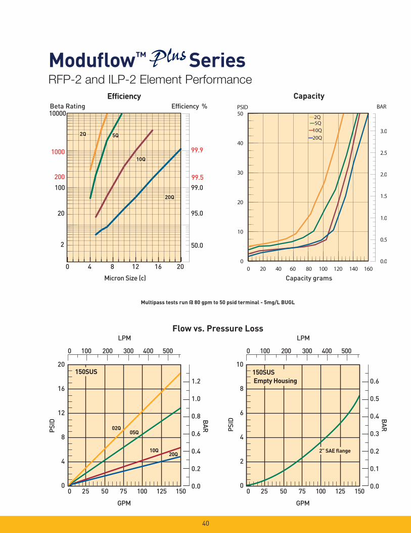
Multipass tests run @ 80 gpm to 50 psid terminal - 5mg/L BUGL
RFP-2 and ILP-2 Element Performance
Modufl ow™ SeriesCapacity
Capacity grams
41
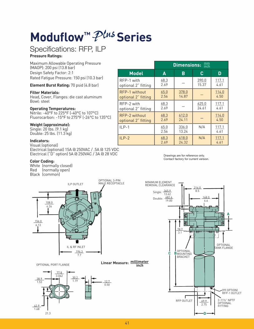
Pressure Ratings:
Maximum Allowable Operating Pressure (MAOP): 200 psi (13.8 bar)
Design Safety Factor: 2:1
Rated Fatigue Pressure: 150 psi (10.3 bar)
Element Burst Rating: 70 psid (4.8 bar)
Filter Materials: Head, Cover, Flanges: die cast aluminumBowl: steel
Operating Temperatures:Nitrile: -40°F to 225°F (-40°C to 107°C)Fluorocarbon: -15°F to 275°F (-26°C to 135°C)
Weight (approximate):Single: 20 lbs. (9.1 kg)Double: 25 lbs. (11.3 kg)
Indicators:Visual (optional)Electrical (optional) 15A @ 250VAC / .5A @ 125 VDCElectrical (“D” option) 5A @ 250VAC / 3A @ 28 VDC
Color Coding: White (normally closed)Red (normally open)Black (common)
168.06.6
A
OPTIONALTANK FLANGE
(99 OPTION) RFP-1 OUTLET
2-11½” NPTFOPTIONALFITTING
69.9
2.75
D
RFP OUTLET
BCOPTIONAL MOUNTING BRACKET
78.73.1
MINIMUM ELEMENT REMOVAL CLEARANCE
345.913.62
482.619.00
Single:
Double:
156.0
6.13
108.0
4.26
196.3
7.7
OPTIONAL 3-PINMALE RECEPTACLEILP OUTLET
OPTIONAL PORT FLANGE
77.83.062
38.91.53
42.91.68
30.21.19 12.7
0.50
21.3
216.08.5
IL & RF INLET
Linear Measure: millimeterinch
Dimensions: mminch
Model A B C DRFP-1 with
optional 2” fi tting
68.3
2.69_ 390.0
15.37
117.1
4.61
RFP-1 without
optional 2” fi tting
65.0
2.56
378.0
14.87_ 114.0
4.50
RFP-2 with
optional 2” fi tting
68.3
2.69_ 625.0
24.61
117.1
4.61
RFP-2 without
optional 2” fi tting
68.3
2.69
612.0
24.11_ 114.0
4.50
ILP-1 65.0
2.56
336.0
13.24
N/A 117.1
4.61
ILP-2 68.3
2.69
618.0
24.32
N/A 117.1
4.61
Specifi cations: RFP, ILP
Modufl ow™ Series
Drawings are for reference only. Contact factory for current version.

42
467.018.38
30.2
1.19
OPTIONALFLANGE
345.9
13.62
INLET
OUTLET
AIR BLEED EACH FILTER
177.87.00
402.815.86
OPTIONAL MECHANICAL INDICATOR
SINGLE
DOUBLE
¼-18 NPTDRAIN VENT
CONNECT TO TANK 173.0
6.81
½-13 SHCSTORQUE
32-38 FT-LB
110.54.61
79.03.11
116.84.60
76.2
617.524.31
330.213.0
3.00
25
20
15
10
5
1.75
1.5
1.25
0.75
0.5
0.25
0
1
FLOW LP MGPM
BAR
PSID
DIF
F. P
RESS
URE
0 10 20 30 40 50 60 70 80 90 100
0 25 50 75 100 125 375150 175 200 225 250 275 300 325
3000 SUS
200 SUS
(Add to differential pressure of filter assembly (Add to differential pressure of filter assembly for total duplex pressure differential) for total duplex pressure differential) *Diverter/check valves combined *Diverter/check valves combined
(Add to differential pressure of filter assembly for total duplex pressure differential) *Diverter/check valves combined
Typical Flow/Pressure Curves For Duplex ValvesApproximate handle torque required for changeover.
System Pressure (psi)
Torq
ue (
Ft-L
bs)
30
20
10
100 200 30000
3.3.013
Linear Measure: millimeterinch
BOTH CHECK VALVESMOVE SAME DIRECTION
FILTER SCHEMATIC
DRAIN VENT
BYPASS BYPASS
FILTERFILTER
OUTLET
INLET
Specifi cations: DILP
Modufl ow™ Series Drawings are for reference only. Contact factory for current version.
Pressure Ratings:
Maximum Allowable Operating Pressure (MAOP): 200 psi (13.8 bar)
Design Safety Factor: 2:1
Rated Fatigue Pressure: 150 psi (10.3 bar)
Element Burst Rating: 70 psid (4.8 bar)
Filter Materials: Diverter Valve Assembly: die cast aluminumCheck Valve Assembly: die cast aluminumFilter Assembly: see IL2 specifi cations
Operating Temperatures:Nitrile: -40°F to 225°F (-40°C to 107°C)Fluorocarbon: -15°F to 275°F (-26°C to 135°C)
Weight (approximate):Single: 55 lbs. (24.9 kg) / Double: 65 lbs. (29.5 kg)
Indicators:Visual (optional)Electrical (optional) 15A @ 250VAC / .5A @ 125 VDCElectrical (“D” option) 5A @ 250VAC / 3A @ 28 VDC
Color Coding: White (normally closed)Red (normally open)Black (common)
43
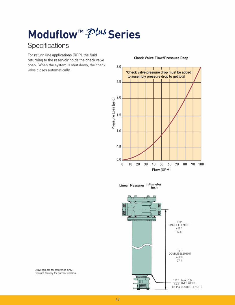
RFPSINGLE ELEMENT
452.1
17.8
RFPDOUBLE ELEMENT
688.3
27.1
MAX. O.D.OVER WELD
117.1
4.61(RFP & DOUBLE LENGTH)
3.0
2.5
2.0
1.5
1.0
0.5
0.0
Flow (GPM)
Pre
ssur
e Lo
ss (p
sid)
Check Valve Flow/Pressure Drop
0 10 20 30 40 50 60 70 80 90 100
*Check valve pressure drop must be added to assembly pressure drop to get total *Check valve pressure drop must be added to assembly pressure drop to get total
Linear Measure: millimeterinch
Specifi cations
Modufl ow™ Series
Drawings are for reference only. Contact factory for current version.
For return line applications (RFP), the fl uid
returning to the reservoir holds the check valve
open. When the system is shut down, the check
valve closes automatically.
44
38B6
0.7
0.6
0.5
0.4
0.3
0.2
0.1
0
10
8
6
4
2
00 5025 75 100 125 150 175 200 225
(PSI
)D
IFF.
PRE
SS.
(BA
R)
(GPM) INLET FLOW (LPM)
0 450 525 600 675
TYPICAL FLOW/PRESSURE CURVES FOR MODEL MM
750 825 900
250
37575 150 225 300
200
SUS
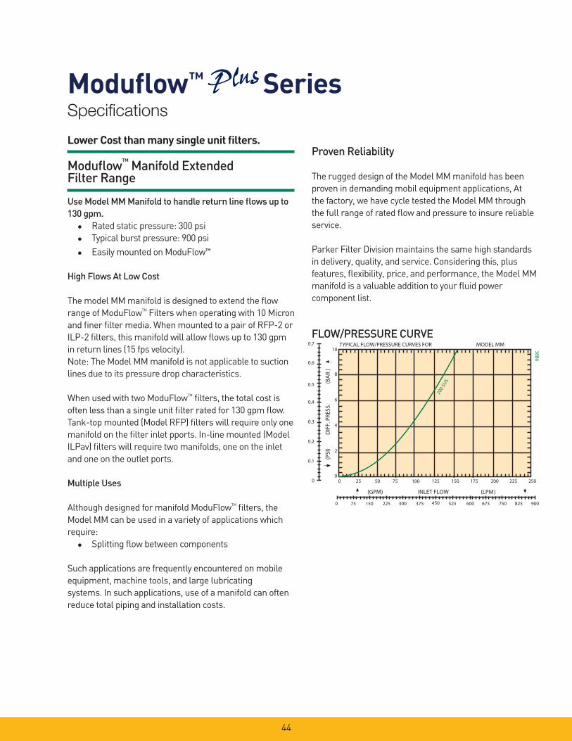
Lower Cost than many single unit fi lters.
Modufl ow™ Manifold Extended Filter Range
Use Model MM Manifold to handle return line fl ows up to 130 gpm.� � Rated static pressure: 300 psi
� � Typical burst pressure: 900 psi
� � Easily mounted on ModuFlow™
High Flows At Low Cost
The model MM manifold is designed to extend the fl ow
range of ModuFlowTM
Filters when operating with 10 Micron
and fi ner fi lter media. When mounted to a pair of RFP-2 or
ILP-2 fi lters, this manifold will allow fl ows up to 130 gpm
in return lines (15 fps velocity).
Note: The Model MM manifold is not applicable to suction
lines due to its pressure drop characteristics.
When used with two ModuFlowTM
fi lters, the total cost is
often less than a single unit fi lter rated for 130 gpm fl ow.
Tank-top mounted (Model RFP) fi lters will require only one
manifold on the fi lter inlet pports. In-line mounted (Model
ILPav) fi lters will require two manifolds, one on the inlet
and one on the outlet ports.
Multiple Uses
Although designed for manifold ModuFlowTM
fi lters, the
Model MM can be used in a variety of applications which
require:
� Splitting fl ow between components
Such applications are frequently encountered on mobile
equipment, machine tools, and large lubricating
systems. In such applications, use of a manifold can often
reduce total piping and installation costs.
Proven Reliability
The rugged design of the Model MM manifold has been
proven in demanding mobil equipment applications, At
the factory, we have cycle tested the Model MM through
the full range of rated fl ow and pressure to insure reliable
service.
Parker Filter Division maintains the same high standards
in delivery, quality, and service. Considering this, plus
features, fl exibility, price, and performance, the Model MM
manifold is a valuable addition to your fl uid power
component list.
FLOW/PRESSURE CURVE
Specifi cations
Modufl ow™ Series

45
Specifi cations
Modufl ow™ Series
155.6mm 6.125
88.9mm 3.50
12.7mm .50 177.8mm
7.00 88.9mm 3.50
66.8mm 2.63
66.8mm 2.63
77.8mm 3.062 42.9mm
1.688
(TORQUE SCREWS TO 32-38 FT-LBS)
C C
273.8mm 10.78
42.9mm 1.688
77.8mm 3.062
(TORQUE SCREWS TO 32-38 FT-LBS)
VIEW AT C-C
STANDARD OUTLET, 2 PLS 2-0 SAE 4-BOLT FLANGE WITH 2-228 O-RING GROOVE
To one decimal place: To two decimal places: To three decimal places: Linear Measure:
TOLERANCES 3.0mm
0.12
0.8mm 0.03
0.4mm 0.015
Millimeter Inch
INSTALLATION DIMENSIONS
HOW TO ORDER MANIFOLDS:
MANIFOLD SPECIFICATIONS
Rated Static Pressure, maximum:
20.7 bar (300 psi)
Typical Burst Pressure:
62.1 bar (900 psi)
Operating Temperature (Buna seals):
+121ºC to —40ºC (+250ºF to 40ºF)
Housing Material:
ANSI 356-T6 cast aluminum
Approximate Shipping Weight:
3.6 kg (8 lbs)
Porting: See Options Below
Order Screws and O-Rings Seperately:
Inlet & outlet screws (12 required):
Order P/N 900228
Outlet port o-rings (2 required):
Nitrite: Order P/N N72228
Fluorocarbon: Order P/N V92228
* Tank-top mounted RFP fi lters will require one manifold on fi lter inlets: in-line mounted ILP fi lters will require two manifolds on both inlets and outlets.
Part Number Description
926466 Modufl ow Manifold
Drawings are for reference only. Contact factory for current version.

46
Accessories
Modufl ow™ Series
OPTIONAL MOUNTING BRACKET (924904)
Linear Measure: millimeterinch
122.94.84
161.56.5
114.34.500
13.50.531
DIA. THRU4 PLACES
114.34.500
R
60TYP 7.9
0.31
8.70.344
DIA. THRUPLACES
6.440.25
114.3 4.500
25.41.00
57.2 2.25
13.5 .531
41.11.62
DIA. THRU TYP.
“M” OPTION-VISUAL INDICATOR, NO ELEMENT WARNING
“E” OPTION-ELECTRICAL INDICATOR
Drawings are for reference only. Contact factory for current version.
47
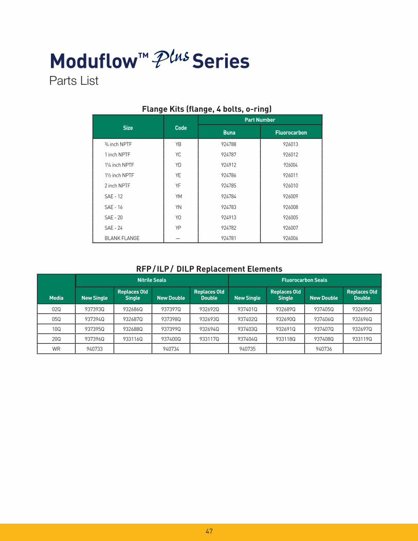
RFP / ILP / DILP Replacement Elements
Flange Kits (fl ange, 4 bolts, o-ring)
Size CodeBuna Fluorocarbon
¾ inch NPTF YB 924788 926013
1 inch NPTF YC 924787 926012
1¼ inch NPTF YD 924912 926004
1½ inch NPTF YE 924786 926011
2 inch NPTF YF 924785 926010
SAE - 12 YM 924784 926009
SAE - 16 YN 924783 926008
SAE - 20 YO 924913 926005
SAE - 24 YP 924782 926007
BLANK FLANGE — 924781 926006
Part Number
Media New SingleReplaces Old
Single New DoubleReplaces Old
Double New SingleReplaces Old
Single New DoubleReplaces Old
Double
02Q 937393Q 932686Q 937397Q 932692Q 937401Q 932689Q 937405Q 932695Q
05Q 937394Q 932687Q 937398Q 932693Q 937402Q 932690Q 937406Q 932696Q
10Q 937395Q 932688Q 937399Q 932694Q 937403Q 932691Q 937407Q 932697Q
20Q 937396Q 933116Q 937400Q 933117Q 937404Q 933118Q 937408Q 933119Q
WR 940733 940734 940735 940736
Nitrile Seals Fluorocarbon Seals
Parts List
Modufl ow™ Series

48
6
4 10 11
35
21
6 78
9
12
15
14
13
Filter AssemblyExploded View
16 17
Parts List
Modufl ow™ SeriesIndex Description Part No. Quantity
11 Check Valve Assy. ......................... 925120 1
12 Flange Kits..................................... O-Ring
Refer to TableV72228
11
13 Plug Kit, Fastener, self-sealing, o-ring seal included with fastener
925974 2
14 Indicator Electrical35 psid.............................................35 psid, 3-pin male receptacle.....GasketO-Ring
926643926753926126V72010
Optional
22
15 Indicator Visual35 psid 4-band...............................
Bracket, Inline mounting...........Indicator Kit, Remote mount.....
926748924904924894
Optional
OptionalOptional
16
17
Not
Shown
Not
Shown
Changeover Valve Assy., Duplex
Check Valve Assy., Duplex............
Drain Plug, SAE-24 for RFP modelNitrile............................................Fluorocarbon................................
O-Ring between tank and bowl
926758
926757
909992928363
N72265
Optional
Optional
11
1
Index Description Part No. Quantity
1 Screws, Nameplate....................... 900028 2
2 Name Plate, Unstamped............... 920928 1
3 Cover Screws, 5/16-18 UNC x 1”.. 926633 6
4 Bowl Screws, 5/16-18 UNC x 1”... 926633 6
5 Cover, Without nameplate............ 924634 1
6 O-Ring, coverNitrile............................................Fluorocarbon................................
N72350V72350
22
7 Element SealNitrile............................................Fluorocarbon................................
937410937411
11
8 Element.......................................... Refer to Table 1
9 Head, Machined only..................... 2” SAE Flange
1½”SAE Flange
1½” NPTF
925972926146925949
111
10 Bowl, Select desired model ILP-1.............................................ILP-2.............................................RFP-1............................................RFP-1 with 2 inch NPTF fi tting...RFP-2............................................RFP-2 with 2 inch NPTF fi tting...
925916924816937626924676937627924818
1
Drawings are for reference only. Contact factory for current version.

49
1) First pair of symbols denotes inlet for all fi lter styles; second pair of symbols denotes outlet.
2) Four symbols required: two for inlet, two for outlet.
3) Unused ports in fi lters come plugged with a blank fl ange.
4) See Flange Kits table for port fl ange options. Flange Kits are ordered separately.
BOX 1 BOX 2 BOX 3 BOX 4 BOX 5 BOX 6 BOX 7 BOX 8
ILP 1 10Q B MP 35 Y9Y9 1BOX 1: Filter Series Symbol Description
RFP Return-line fi lter, inlet on
side outlet on bottom
ILP In-line fi lter
DILP In-line duplex
Filter Model
Y9 2” fl ange face 99 No fi tting
RFP P9 SAE-24integral threads
F9 2” NPTF
F8 External check
valve
Y9 2” fl ange face Y9 2” fl ange face
ILP P9 SAE-24
integral threads
P9 SAE-24 integral
threads
E9 1½ NPTF
integral threads
Y9 2” fl ange face Y9 2” fl ange face
BOX 7: Port Options
InletSymbol/Description
OutletSymbol/Description
DILP
Note: First letter of indicator code = left side of fi lter head when looking into inlet with bowl down; second letter = right side of fi lter head when looking into inlet with bowl down.
BOX 2: Element Length Symbol Description
1 Single
2 Double
BOX 3: Media Code Symbol Description
02Q Microglass III, 2 micron
05Q Microglass III, 5 micron
10Q Microglass III, 10 micron
20Q Microglass III, 20 micron
WR Water Removal
BOX 4: SealsSymbol Description
B Nitrile
E EPR
V Fluorocarbon
BOX 5: IndicatorSymbol Description
P Pressure ports drilled &
plugged only; no indicator
M Visual indicator w/”no
element” warning
E Electrical indicator only
D Electrical indicator only,
3-pin male receptacle
BOX 6: Bypass Setting Symbol Description
35 35 psid
BOX 8: Options Symbol Description
1 None
How to Order
Modufl ow™ Series
50
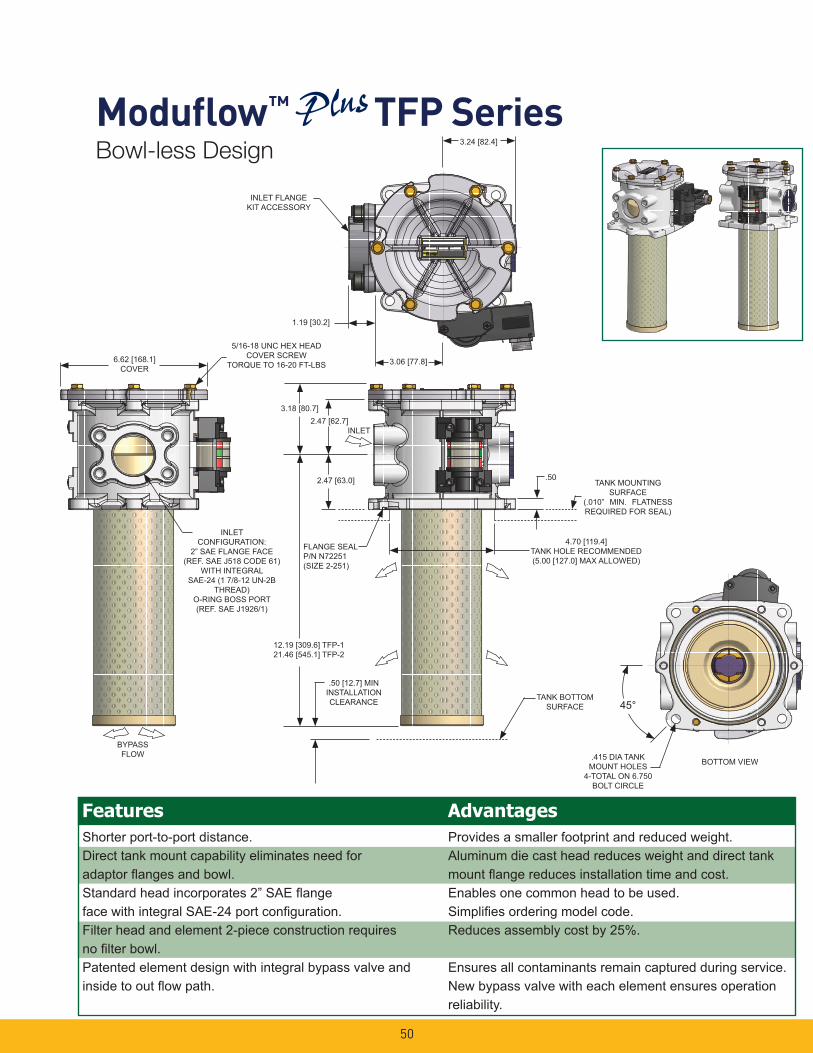
Bowl-less Design
INLET FLANGEKIT ACCESSORY
3.24 [82.4]
1.19 [30.2]
3.06 [77.8]
2.47 [62.7]3.18 [80.7]
2.47 [63.0]
INLET
FLANGE SEALP/N N72251(SIZE 2-251)
12.19 [309.6] TFP-121.46 [545.1] TFP-2
TANK MOUNTINGSURFACE
(.010” MIN. FLATNESS REQUIRED FOR SEAL)
4.70 [119.4]TANK HOLE RECOMMENDED(5.00 [127.0] MAX ALLOWED)
.50 [12.7] MININSTALLATIONCLEARANCE TANK BOTTOM
SURFACE
INLETCONFIGURATION:
2” SAE FLANGE FACE(REF. SAE J518 CODE 61)
WITH INTEGRALSAE-24 (1 7/8-12 UN-2B
THREAD)O-RING BOSS PORT(REF. SAE J1926/1)
6.62 [168.1]COVER
5/16-18 UNC HEX HEADCOVER SCREW
TORQUE TO 16-20 FT-LBS
BYPASSFLOW
.50
BOTTOM VIEW.415 DIA TANKMOUNT HOLES
4-TOTAL ON 6.750BOLT CIRCLE
Shorter port-to-port distance.Direct tank mount capability eliminates need foradaptor fl anges and bowl.Standard head incorporates 2” SAE fl angeface with integral SAE-24 port confi guration.Filter head and element 2-piece construction requiresno fi lter bowl.Patented element design with integral bypass valve andinside to out fl ow path.
Provides a smaller footprint and reduced weight.Aluminum die cast head reduces weight and direct tankmount fl ange reduces installation time and cost.Enables one common head to be used.Simplifi es ordering model code.Reduces assembly cost by 25%.
Ensures all contaminants remain captured during service.New bypass valve with each element ensures operationreliability.
Features Advantages
45°
Modufl ow™ TFP Series
51
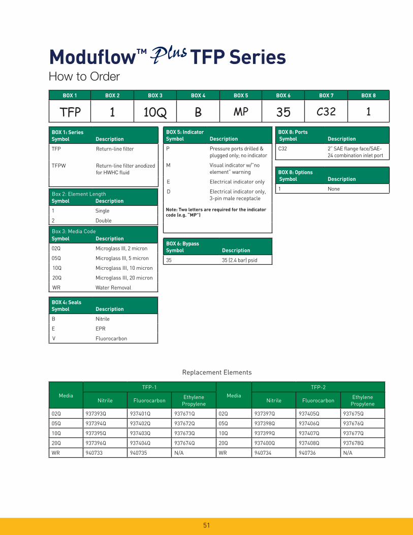
BOX 1 BOX 2 BOX 3 BOX 4 BOX 5 BOX 6 BOX 7 BOX 8
TFP 1 10Q B MP 35 C32 1
Note: Two letters are required for the indicator code (e.g. “MP”)
Symbol Description
1 Single
2 Double
Symbol Description
02Q Microglass III, 2 micron
05Q Microglass III, 5 micron
10Q Microglass III, 10 micron
20Q Microglass III, 20 micron
WR Water Removal
BOX 4: SealsSymbol Description
B Nitrile
E EPR
V Fluorocarbon
BOX 5: IndicatorSymbol Description
P Pressure ports drilled &
plugged only; no indicator
M Visual indicator w/”no
element” warning
E Electrical indicator only
D Electrical indicator only,
3-pin male receptacle
BOX 6: BypassSymbol Description
35 35 (2.4 bar) psid
BOX 8: Options Symbol Description
1 None
BOX 1: Series Symbol Description
TFP Return-line fi lter
TFPW Return-line fi lter anodized
for HWHC fl uid
Box 2: Element Length
Box 3: Media Code
BOX 8: Ports Symbol Description
C32 2” SAE fl ange face/SAE-
24 combination inlet port
Media
TFP-1
Media
TFP-2
Nitrile FluorocarbonEthylene
PropyleneNitrile Fluorocarbon
Ethylene
Propylene
02Q 937393Q 937401Q 937671Q 02Q 937397Q 937405Q 937675Q
05Q 937394Q 937402Q 937672Q 05Q 937398Q 937406Q 937676Q
10Q 937395Q 937403Q 937673Q 10Q 937399Q 937407Q 937677Q
20Q 937396Q 937404Q 937674Q 20Q 937400Q 937408Q 937678Q
WR 940733 940735 N/A WR 940734 940736 N/A
Replacement Elements
How to Order
Modufl ow™ TFP Series
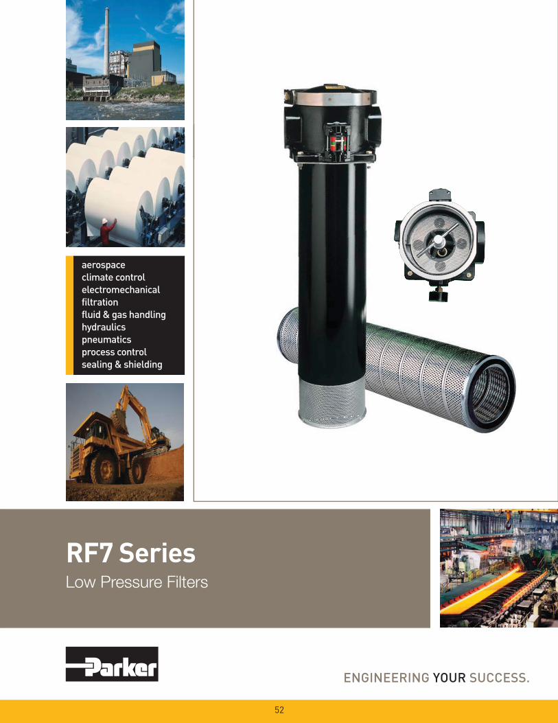
RF7 SeriesLow Pressure Filters
52
53
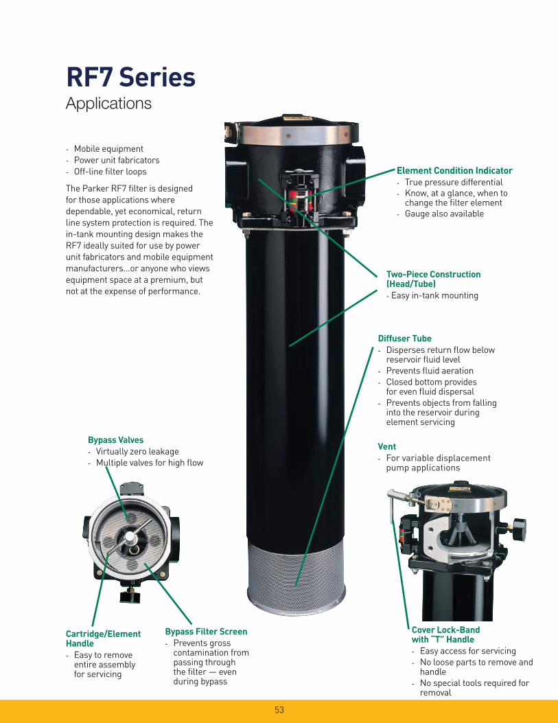
RF7 SeriesApplications
Element Condition Indicator- True pressure differential
- Know, at a glance, when to change the fi lter element
- Gauge also available
Diffuser Tube- Disperses return fl ow below
reservoir fl uid level
- Prevents fl uid aeration
- Closed bottom provides for even fl uid dispersal
- Prevents objects from falling into the reservoir during element servicing
Cartridge/Element Handle- Easy to remove
entire assembly for servicing
Cover Lock-Band with “T” Handle- Easy access for servicing
- No loose parts to remove and handle
- No special tools required for removal
Two-Piece Construction(Head/Tube)- Easy in-tank mounting
Bypass Filter Screen- Prevents gross
contamination from passing through the fi lter — even during bypass
- Mobile equipment
- Power unit fabricators
- Off-line fi lter loops
The Parker RF7 fi lter is designed
for those applications where
depend able, yet economical, return
line system protection is required. The
in-tank mounting design makes the
RF7 ideally suited for use by power
unit fabricators and mobile equipment
manufacturers...or anyone who views
equipment space at a premium, but
not at the expense of performance.
Bypass Valves- Virtually zero leakage
- Multiple valves for high fl ow
Vent- For variable displacement
pump applications
54
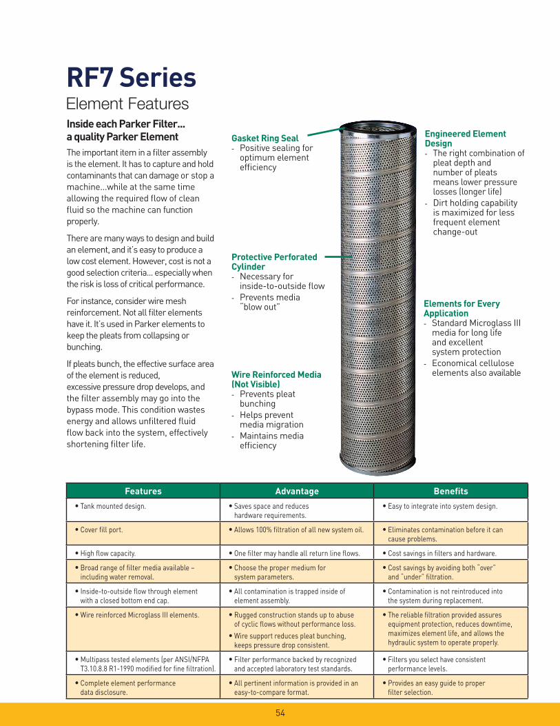
RF7 SeriesElement Features
Gasket Ring Seal- Positive sealing for
optimum element effi ciency
Inside each Parker Filter... a quality Parker ElementThe important item in a fi lter assembly
is the element. It has to capture and hold
contaminants that can damage or stop a
machine...while at the same time
allowing the required fl ow of clean
fl uid so the machine can function
properly.
There are many ways to design and build
an element, and it’s easy to produce a
low cost element. However, cost is not a
good selection criteria... especially when
the risk is loss of critical performance.
For instance, consider wire mesh
reinforcement. Not all fi lter elements
have it. It’s used in Parker elements to
keep the pleats from collapsing or
bunching.
If pleats bunch, the effective surface area
of the element is reduced,
excessive pressure drop develops, and
the fi lter assembly may go into the
bypass mode. This condition wastes
energy and allows unfi ltered fl uid
fl ow back into the system, effectively
shortening fi lter life.
Protective Perforated Cylinder- Necessary for
inside-to-outside fl ow
- Prevents media“blow out”
Wire Reinforced Media(Not Visible)- Prevents pleat
bunching
- Helps prevent media migration
- Maintains media effi ciency
Engineered Element Design- The right combination of
pleat depth and number of pleats means lower pressure losses (longer life)
- Dirt holding capability is maximized for less frequent element change-out
Elements for Every Application- Standard Microglass III
media for long life and excellent system protection
- Economical cellulose elements also available
Features Advantage Benefi ts
• Tank mounted design. • Saves space and reduces hardware requirements.
• Easy to integrate into system design.
• Cover fi ll port. • Allows 100% fi ltration of all new system oil. • Eliminates contamination before it can cause problems.
• High fl ow capacity. • One fi lter may handle all return line fl ows. • Cost savings in fi lters and hardware.
• Broad range of fi lter media available – including water removal.
• Choose the proper medium for system parameters.
• Cost savings by avoiding both “over” and “under” fi ltration.
• Inside-to-outside fl ow through element with a closed bottom end cap.
• All contamination is trapped inside of element assembly.
• Contamination is not reintroduced into the system during replacement.
• Wire reinforced Microglass III elements. • Rugged construction stands up to abuse of cyclic fl ows without performance loss.
• Wire support reduces pleat bunching, keeps pressure drop consistent.
• The reliable fi ltration provided assures equipment protection, reduces downtime, maximizes element life, and allows the hydraulic system to operate properly.
• Multipass tested elements (per ANSI/NFPA T3.10.8.8 R1-1990 modifi ed for fi ne fi ltration).
• Filter performance backed by recognized and accepted laboratory test standards.
• Filters you select have consistent performance levels.
• Complete element performance data disclosure.
• All pertinent information is provided in an easy-to-compare format.
• Provides an easy guide to proper fi lter selection.
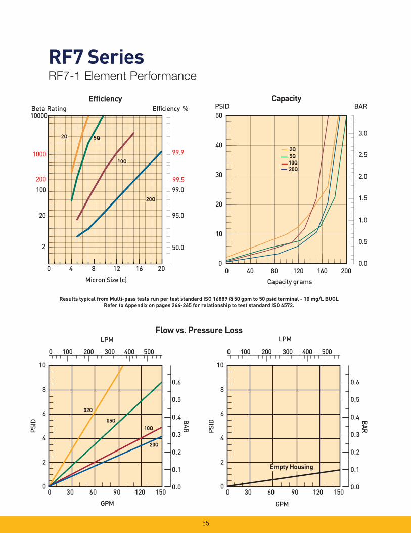
RF7 SeriesRF7-1 Element Performance
55
Efficiency %Efficiency
Beta Rating
1000
10000
99.9
99.599.0100
200
20
2 50.0
95.0
Micron Size (c)
2Q
10Q
20Q
2Q
10Q
20Q
2Q
10Q
20Q
5Q5Q
0 4 8 12 16 20
0 100 200 300 400 500
0 30 60 90 120 150
10
8
6
4
2
0
02Q
20Q
10Q05Q
LPM
PSID
GPM
0.6
0.5
0.4
0.3
0.2
0.1
0.0
BAR
0 100 200 300 400 500
0 30 60 90 120 150
10
8
6
4
2
0
LPM
PSID
GPM
0.6
0.5
0.4
0.3
0.2
0.1
0.0
BAR
Empty Housing
Flow vs. Pressure Loss
0.0
0.5
1.0
1.5
2.0
2.5
3.0
0 40 80 120 160 200
Capacity grams
0
10
20
30
40
50 PSID BAR
Capacity
2Q5Q
20Q10Q
Results typical from Multi-pass tests run per test standard ISO 16889 @ 50 gpm to 50 psid terminal - 10 mg/L BUGLRefer to Appendix on pages 264-265 for relationship to test standard ISO 4572.

RF7 SeriesRF7-2 Element Performance
56
Efficiency %Efficiency
Beta Rating
1000
10000
99.9
99.599.0100
200
20
2 50.0
95.0
Micron Size (c)
2Q
10Q
20Q
2Q
10Q
20Q
2Q
10Q
20Q
5Q5Q
0 4 8 12 16 20
0 200 400 600 800 1000
0 50 100 150 200 250 300
10
8
6
4
2
0
02Q
20Q
10Q
05Q
LPM
PSID
GPM
0.6
0.5
0.4
0.3
0.2
0.1
0.0
BAR
150SUS
0 200 400 600 800 1000
0 50 100 150 200 250 300
10
8
6
4
2
0
LPM
PSID
GPM
0.6
0.5
0.4
0.3
0.2
0.1
0.0
BAR
Empty Housing
150SUS
Results typical from Multi-pass tests run per test standard ISO 16889 @ 80 gpm to 50 psid terminal - 10 mg/L BUGLRefer to Appendix on pages 264-265 for relationship to test standard ISO 4572.
Flow vs. Pressure Loss
0.0
0.5
1.0
1.5
2.0
2.5
3.0
0
10
20
30
40
50
0 60 120 180 240 300 360 420
Capacity grams
PSID BAR Capacity
2Q
20Q10Q5Q
RF7 SeriesSpecifi cations
57
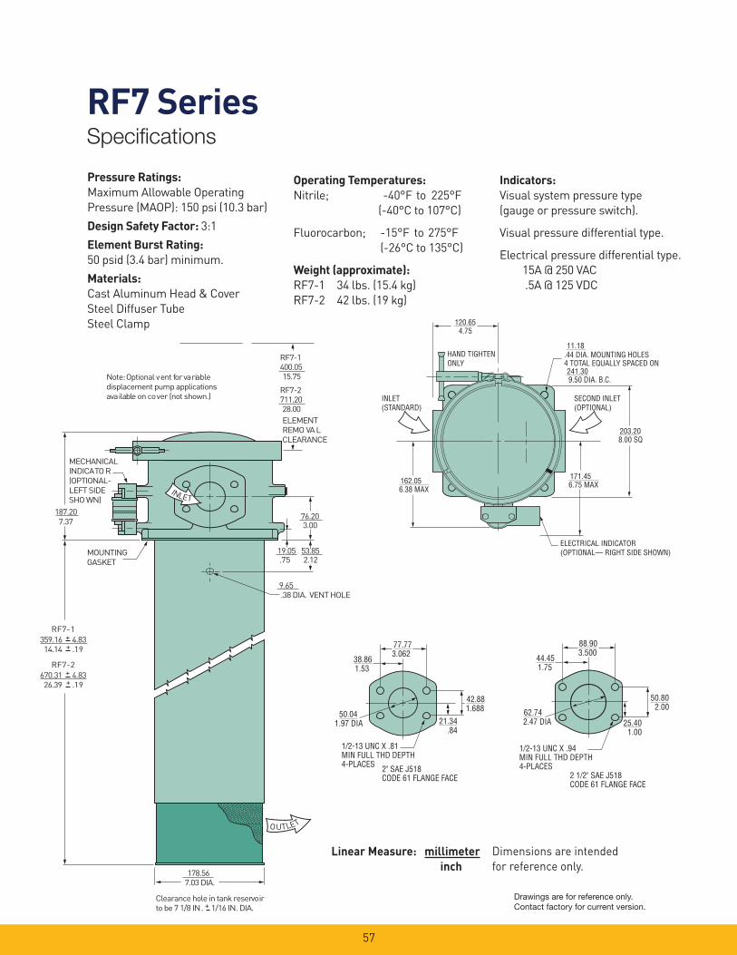
Pressure Ratings:Maximum Allowable Operating
Pressure (MAOP): 150 psi (10.3 bar)
Design Safety Factor: 3:1
Element Burst Rating: 50 psid (3.4 bar) minimum.
Materials: Cast Aluminum Head & Cover
Steel Diffuser Tube
Steel Clamp
Operating Temperatures:Nitrile; -40°F to 225°F
(-40°C to 107°C)
Fluorocarbon; -15°F to 275°F
(-26°C to 135°C)
Weight (approximate):RF7-1 34 lbs. (15.4 kg)
RF7-2 42 lbs. (19 kg)
Indicators:Visual system pressure type
(gauge or pressure switch).
Visual pressure differential type.
Electrical pressure differential type.
15A @ 250 VAC
.5A @ 125 VDC
711.20
MOUNTING
GASKET
28.00
3.00
. 38 DIA. VENT HOLE
7.37
MECHANICAL
I NDICA TO R
(OPTIONAL-
LEFT SIDE
SHO WN)
7.03 DIA.
I N L E T
O U T L E T
187.20 76.20
.7 5 19.05
9.65
2.12 53.85
178.56
Clearance hole in tank reser vo ir
to be 7 1/8 IN . + 1/16 IN . DIA.
670.31 + 4.83 + .1 9 26.39
RF7- 2
359.16 + 4.83 + .1 9 14.14
RF7- 1
Note: Optional v ent f or va ri ab le
displacement pump applications
ava ila bl e on co v er (not sho wn. )
ELEMENT
REMO VA L
CLEARANCE
RF7-2
400.05 15.75
RF7-1
1/2-13 UNC X .81MIN FULL THD DEPTH4-PLACES 2" SAE J518
CODE 61 FLANGE FACE
3.06277.77
1.5338.86
1.97 DIA50.04
.8421.34
1.68842.88
1/2-13 UNC X .94MIN FULL THD DEPTH4-PLACES
3.50088.90
1.7544.45
2.47 DIA62.74
1.0025.40
2.0050.80
2 1/2" SAE J518CODE 61 FLANGE FACE
.44 DIA. MOUNTING HOLES4 TOTAL EQUALLY SPACED ON
HAND TIGHTENONLY
ELECTRICAL INDICATOR(OPTIONAL— RIGHT SIDE SHOWN)
4.75120.65
11.18
9.50 DIA. B.C.241.30
8.00 SQ203.20
6.75 MAX171.45
6.38 MAX162.05
INLET(STANDARD)
SECOND INLET(OPTIONAL)
Dimensions are intended
for reference only.
Linear Measure: millimeter inch
Drawings are for reference only. Contact factory for current version.
RF7 SeriesSpecifi cations
58
138
7
6 5
4
3
17
16
11
10
9 2151 19
18
14
12
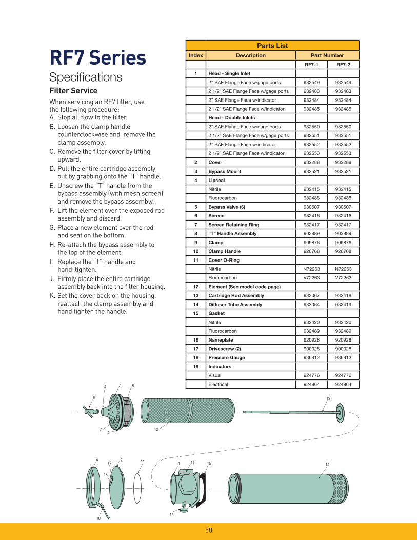
Filter ServiceWhen servicing an RF7 fi lter, use the following procedure:A. Stop all fl ow to the fi lter.
B. Loosen the clamp handle counterclockwise and remove the clamp assembly.
C. Remove the fi lter cover by lifting upward.
D. Pull the entire cartridge assembly out by grabbing onto the “T” handle.
E. Unscrew the “T” handle from the bypass assembly (with mesh screen) and remove the bypass assembly.
F. Lift the element over the exposed rod assembly and discard.
G. Place a new element over the rod and seat on the bottom.
H. Re-attach the bypass assembly to the top of the element.
I. Replace the “T” handle and hand-tighten.
J. Firmly place the entire cartridge assembly back into the fi lter housing.
K. Set the cover back on the housing, reattach the clamp assembly and hand tighten the handle.
Parts List
Index Description Part Number
RF7-1 RF7-2
1 Head - Single Inlet
2” SAE Flange Face w/gage ports 932549 932549
2 1/2” SAE Flange Face w/gage ports 932483 932483
2” SAE Flange Face w/indicator 932484 932484
2 1/2” SAE Flange Face w/indicator 932485 932485
Head - Double Inlets
2” SAE Flange Face w/gage ports 932550 932550
2 1/2” SAE Flange Face w/gage ports 932551 932551
2” SAE Flange Face w/indicator 932552 932552
2 1/2” SAE Flange Face w/indicator 932553 932553
2 Cover 932288 932288
3 Bypass Mount 932521 932521
4 Lipseal
Nitrile 932415 932415
Fluorocarbon 932488 932488
5 Bypass Valve (6) 930507 930507
6 Screen 932416 932416
7 Screen Retaining Ring 932417 932417
8 “T” Handle Assembly 903889 903889
9 Clamp 909876 909876
10 Clamp Handle 926768 926768
11 Cover O-Ring
Nitrile N72263 N72263
Flourocarbon V72263 V72263
12 Element (See model code page)
13 Cartridge Rod Assembly 933067 932418
14 Diffuser Tube Assembly 933064 932419
15 Gasket
Nitrile 932420 932420
Fluorocarbon 932489 932489
16 Nameplate 920928 920928
17 Drivescrew (2) 900028 900028
18 Pressure Gauge 936912 936912
19 Indicators
Visual 924776 924776
Electrical 924964 924964
59
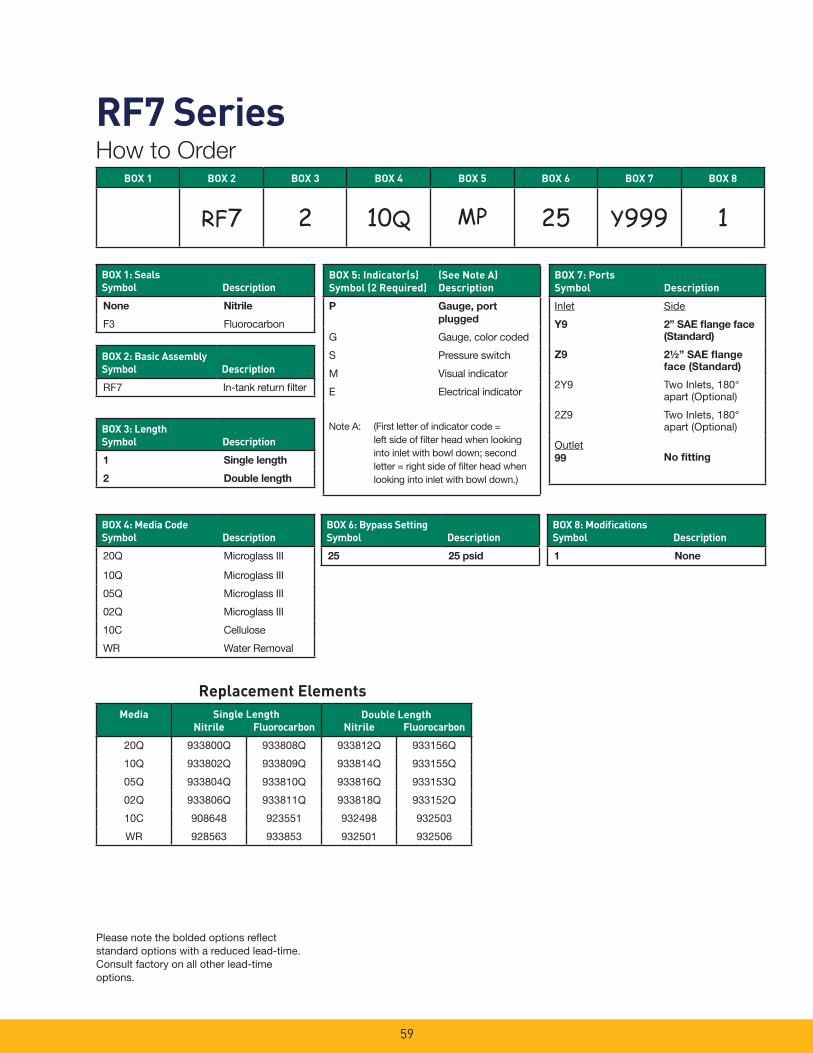
RF7 SeriesHow to Order
Replacement Elements
Please note the bolded options refl ect standard options with a reduced lead-time. Consult factory on all other lead-time options.
BOX 1 BOX 2 BOX 3 BOX 4 BOX 5 BOX 6 BOX 7 BOX 8
RF7 2 10Q MP 25 Y999 1
BOX 1: SealsSymbol Description
None Nitrile
F3 Fluorocarbon
BOX 2: Basic AssemblySymbol Description
RF7 In-tank return fi lter
BOX 3: LengthSymbol Description
1 Single length
2 Double length
BOX 5: Indicator(s)Symbol (2 Required)
(See Note A)Description
P Gauge, port
plugged
G Gauge, color coded
S Pressure switch
M Visual indicator
E Electrical indicator
Note A: (First letter of indicator code = left side of fi lter head when looking into inlet with bowl down; second letter = right side of fi lter head when looking into inlet with bowl down.)
BOX 7: PortsSymbol Description
Inlet Side
Y9 2” SAE fl ange face
(Standard)
Z9 2½” SAE fl ange
face (Standard)
2Y9 Two Inlets, 180° apart (Optional)
2Z9 Two Inlets, 180° apart (Optional)
Outlet99 No fi tting
BOX 4: Media Code Symbol Description
20Q Microglass III
10Q Microglass III
05Q Microglass III
02Q Microglass III
10C Cellulose
WR Water Removal
BOX 6: Bypass SettingSymbol Description
25 25 psid
BOX 8: Modifi cationsSymbol Description
1 None
MediaNitrile Fluorocarbon Nitrile Fluorocarbon
20Q 933800Q 933808Q 933812Q 933156Q
10Q 933802Q 933809Q 933814Q 933155Q
05Q 933804Q 933810Q 933816Q 933153Q
02Q 933806Q 933811Q 933818Q 933152Q
10C 908648 923551 932498 932503
WR 928563 933853 932501 932506
Single Length Double Length

BGT SeriesLow Pressure Filters
60

61
BGT SeriesApplications
Specifi cations
Housing Data:Material: Head – Aluminum Alloy Diffusor – Steel Internals – Carbon Steel and Aluminum Seals – Nitrile (Standard), Fluorocarbon
Pressure Rating: Static – 150 psi (10.3 bar)
Temperature Range: Operating -40°F to +250°F (-40°C to +120°C)
- Flows to 640 GPM
- 3 Micron Absolute to
120 Micron Absolute
- Disposable or Recleanable Elements
- Visual and Electrical Indicators
- Microglass elements
- Magnetic prefi ltration
- Full fl ow bypass valve
- No internal leakage paths
- Inside-to-out fl ow thru element
- Complete contaminant removal during
element service
- LEIF® element
(600 and 1000 Series only)
BGT Tank Mounted Return Flow Filters
BGT Filters feature Parker’s exclusive
Magnetic Prefi ltration core which collects
ferromagnetic particles from fl uid
upstream of the fi lter element. This feature
alone could save hundreds of dollars
a year by protecting costly equipment
from increased wear and malfunction
by assuring that the fl uid is as pure as
possible when it leaves the fi lter. Even
during bypass due to cold start up, ferris
contaminant is collected by the magnetic
core, a feature of importance on any fl uid
power system.
Take a close look and compare Parker
features with any other fi lter.
1. Fluid fl ows through the inlet port into an
enlarged area which reduces fl uid velocity.
Inlet fl ow does not impinge on the element.
2. Filtration begins with magnetic
prefi ltration of ferromagnetic particles in
the full fl uid fl ow upstream of the element,
not downstream or in the reservoir. Built-in
or system generated ferromagnetic wear
debris (even particles smaller than the
element rating) are collected by the high
strength (3.0K Gauss) magnetic column.
This results in extended element and oil life
and reduced maintenance and downtime,
which reduces overall operating cost.
3. Fluid passes through the element in
an inside-to-outside direction, collecting
particles inside the fi lter cartridge. This
eliminates reinjection of contaminant
during element change. Clean fl uid then
returns to the reservoir through the diffusor
which prevents fl uid aeration.
Normal return line fi lters, that fl ow
outside-to-inside, allow contaminated fl uid
to drain back into the reservoir when the
element is serviced.
4. Simplifi ed bypass design and location
prevents fl ushing previously collected
contaminant back into the system. Since
the element serves as the valve there is
no troublesome separate valve to remove
when changing elements. Magnetic
fi ltration occurs even during bypass. All
potential leakage paths are o-ring sealed
to eliminate bypass leakage that occurs in
loose fi tting valve assemblies.
BGT Filters are available with disposable
elements of several contamination class
levels for use in all common fl uids.
Optional accessories include visual and
electric warning indicators that assure
proper element service.
4
1
2
3

62
BGT Series
DimensionsBGT-13, BGT-15, BGT-17
Example:Element Size Code = 600Element Media Code = 10Filter Factor = .022 (From chart)Flow = 160 GPMViscosity = 160 SSU
Formula: 160 GPM x .022 x (160 SSU/140 SSU) = 4.0 PSID
How To Size Tank Top FiltersElement Pressure Drop Factor:Multiply the actual fl ow rate times the applicable �P factor to determine the pressure drop with a fl uid viscosity of 140 SSU. Correct for other viscosities by applying the following formula: Flow rate (GPM) x fi lter factor x (new viscosity in SSU/140 SSU).
Flow/Pressure Drop DataFluid Conditions: Viscosity-140 SSU Sp. Gr. - 0.88
Element Data
Media Code 600
Size Code1000
2000
02Q (L) .082 .0493 .0246
05Q (L) .031 .0187 .0091
10Q (L) .022 .0129 .0066
20Q (L) .014 .0088 .0044
MediaType
AbsoluteRating
Multipass Test Results To ISO 4572(Time Weighted Averages)
B3 B6 B10 B12 B20 B25 B36
Microglass III 3 �100 800 2000 >5000 � � �
Microglass III 6 8 �100 1000 2000 >5000 � �
Microglass III 10 6 22 �100 �200 >5000 � �
Microglass III 20 – 2 8 20 �100 �200 >5000
Return Line Filter - Series 4Dimensions
inches (mm)
BGT Filter Model
13 15 17
C 18.0 (457) 27.0 (686) 48.0 (1219)
L 16.75 (425) 25.20 (640) 47.25 (1200)
D 9.49/9.47 (241/240.5)
E 10.25/9.70 (260/246)
Drawings are for reference only. Contact factory for current version.

63
BGT SeriesParts List
Parts Breakdown BGT Series
*Please specify seal material suffi x when ordering Fluorocarbon seals: “-V”
2 1
3
4
Element:See How To Order Page
Part Number
BGT13, 15 or 17 Description
R-8875 Cover O-ring
SOR-90 Insert O-ring
SOR-85 Bypass Seals
R9875 Tank Gasket
SOR-115 Element O-Ring
Nitrile or Fluorocarbon Material*
Seals
13, 15 or 17 Pressure
6903184 Blocked
4903020 4.5 PSID
4903004 12 PSID
4903008 22 PSID
Bypass Assembly
Item Description Material BGT-13 BGT-15 BGT-17
1 Top Spring Steel 48371205
2 Cover Die Cast
Aluminum
84.22.064.06(5842206)
3 Head Die Cast
Aluminum
5841032
4 Diffusor Steel 2110084 2110085 21100086
Part Numbers

64
BGT Series
Operating And Maintenance Instructions Parker Model BGT Tank Top Filters
A. Mounting 1. Standard mounting. a. Cut proper size hole in the top
of the reservoir. b. Drill holes for studs within the
proper bolt circle. c. Set the fi lter into the cutout
hole and secure with proper size bolts, nuts and lock washers.
2. Utilize proper fi ttings.
B. Start-Up 1. Check for and eliminate leaks upon
system start-up.
2. Check differential pressure indicator, if installed, to monitor element condition.
C. Service 1. An element must be serviced when
the indicator indicates service is required.
NOTE: If the fi lter is not equipped with an indicator, the element should be serviced according to machine manufacturer’s instructions.
D. Servicing Dirty Elements 1. Shut system down to assure that
there is NO PRESSURE OR FLOW into the fi lter housing.
2. Remove the fi lter cover.
3. Remove the fi lter insert (bridge which holds the element in place).
4. Remove the bypass spring assembly or non-bypass plate from the stud.
5. Remove the contaminated cartridge with a twisting motion.
6. a. Discard the disposable element cartridge.
b. Wash cleanable or mesh elements in a non-caustic solvent. Compressed air can be used to facilitate cleaning. Use care to prevent damage to the element during cleaning.
NOTE: Elements fi ner than 150 microns (100 mesh) may require special ultrasonic cleaning. Consult factory for recommendations.
E. Before Installing A New Element Cartridge
1. Clean the magnetic core with a lint- free cloth.
2. Check all seals and replace if necessary.
F. To Install A New Or Cleaned Element Cartridge
1. Lubricate all seals.
2. Mount new or cleaned Parker fi lter cartridge.
NOTE: For ease of mounting, hold the cartridge away from the magnetic core until the stud is through the hole in the bottom of the element. Then slide it up to securely seat it to the top of the bridge.
3. Install the bypass spring assembly or non-bypass plate, and tighten until snug.
NOTE: Older versions may have a cotter pin/castellated nut retained bypass spring. In these cases, the nut should be turned down the shaft until the cross drilled hole is visible in the base of a castellation and the cotter pin inserted and ends fl ared to lock the bypass assembly in place.
4. Re-install the insert into the fi lter housing, making sure that the top- spring is secure.
5. Re-install the cover. Torque the cover nuts to 22 ft./lbs.
Follow procedures B.1 and B.2.
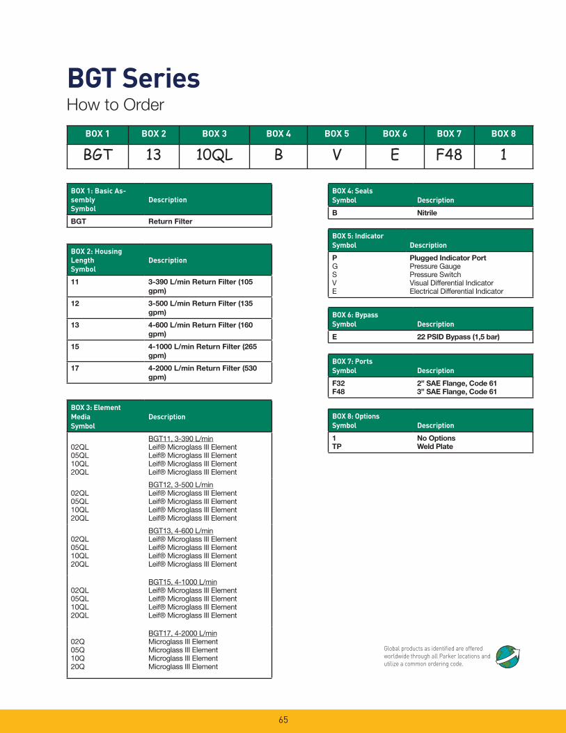
65
BGT SeriesHow to Order
BOX 1 BOX 2 BOX 3 BOX 4 BOX 5 BOX 6 BOX 7 BOX 8
BGT 13 10QL B V E F48 1
BOX 1: Basic As-semblySymbol
Description
BGT Return Filter
BOX 4: SealsSymbol Description
B Nitrile
BOX 2: Housing LengthSymbol
Description
11 3-390 L/min Return Filter (105
gpm)
12 3-500 L/min Return Filter (135
gpm)
13 4-600 L/min Return Filter (160
gpm)
15 4-1000 L/min Return Filter (265
gpm)
17 4-2000 L/min Return Filter (530
gpm)
BOX 3: Element MediaSymbol
Description
02QL05QL10QL20QL
BGT11, 3-390 L/minLeif® Microglass III ElementLeif® Microglass III ElementLeif® Microglass III ElementLeif® Microglass III Element
02QL05QL10QL20QL
BGT12, 3-500 L/minLeif® Microglass III ElementLeif® Microglass III ElementLeif® Microglass III ElementLeif® Microglass III Element
02QL05QL10QL20QL
BGT13, 4-600 L/minLeif® Microglass III ElementLeif® Microglass III ElementLeif® Microglass III ElementLeif® Microglass III Element
02QL05QL10QL20QL
BGT15, 4-1000 L/minLeif® Microglass III ElementLeif® Microglass III ElementLeif® Microglass III ElementLeif® Microglass III Element
02Q05Q10Q20Q
BGT17, 4-2000 L/minMicroglass III ElementMicroglass III ElementMicroglass III ElementMicroglass III Element
BOX 5: IndicatorSymbol Description
P
GSVE
Plugged Indicator Port
Pressure GaugePressure SwitchVisual Differential IndicatorElectrical Differential Indicator
BOX 6: BypassSymbol Description
E 22 PSID Bypass (1,5 bar)
BOX 7: PortsSymbol Description
F32
F48
2” SAE Flange, Code 61
3” SAE Flange, Code 61
BOX 8: OptionsSymbol Description
1
TP
No Options
Weld Plate
Global products as identifi ed are offered worldwide through all Parker locations and utilize a common ordering code.