Embed Size (px)
Citation preview
www.vishay.com For technical questions, contact: [email protected] Document Number: 510591 Revision: 31-May-10
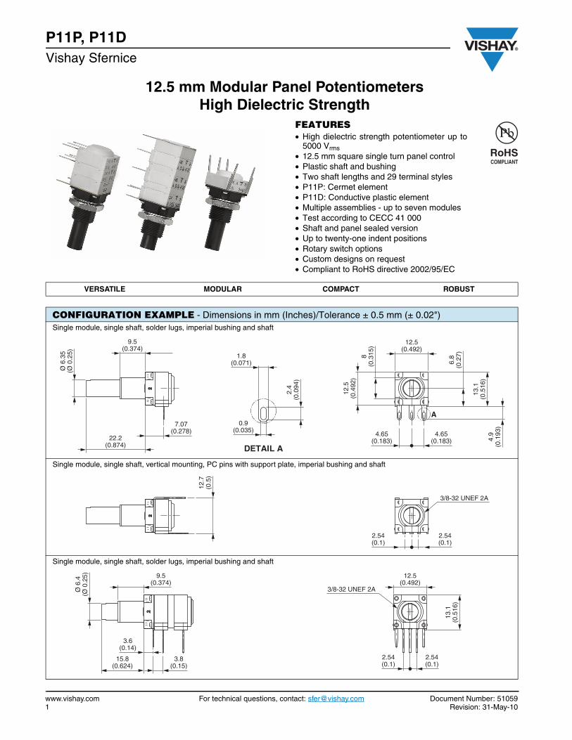
P11P, P11DVishay Sfernice
12.5 mm Modular Panel PotentiometersHigh Dielectric Strength
FEATURES• High dielectric strength potentiometer up to
5000 Vrms• 12.5 mm square single turn panel control• Plastic shaft and bushing• Two shaft lengths and 29 terminal styles• P11P: Cermet element• P11D: Conductive plastic element• Multiple assemblies - up to seven modules• Test according to CECC 41 000• Shaft and panel sealed version• Up to twenty-one indent positions• Rotary switch options• Custom designs on request• Compliant to RoHS directive 2002/95/EC
VERSATILE MODULAR COMPACT ROBUST
CONFIGURATION EXAMPLE - Dimensions in mm (Inches)/Tolerance ± 0.5 mm (± 0.02")Single module, single shaft, solder lugs, imperial bushing and shaft
Single module, single shaft, vertical mounting, PC pins with support plate, imperial bushing and shaft
Single module, single shaft, solder lugs, imperial bushing and shaft
12.5(0.492)
A
8(0
.315
)
12.5
(0.4
92)
6.8
(0.2
7)
13.1
(0.5
16)
4.9
(0.1
93)
4.65(0.183)
4.65(0.183)
DETAIL A
2.4
(0.0
94)
0.9(0.035)
1.8(0.071)
9.5(0.374)
7.07(0.278)
22.2(0.874)
Ø 6
.35
(Ø 0
.25)
3/8-32 UNEF 2A
2.54(0.1)
2.54(0.1)
12.7
(0.5
)
Ø 6
.4(Ø
0.2
5) 9.5(0.374)
3.8(0.15)
15.8(0.624)
3.6(0.14)
12.5(0.492)
3/8-32 UNEF 2A
13.1
(0.5
16)
2.54(0.1)
2.54(0.1)
Document Number: 51059 For technical questions, contact: [email protected] www.vishay.comRevision: 31-May-10 2
P11P, P11D12.5 mm Modular Panel Potentiometers
High Dielectric StrengthVishay Sfernice
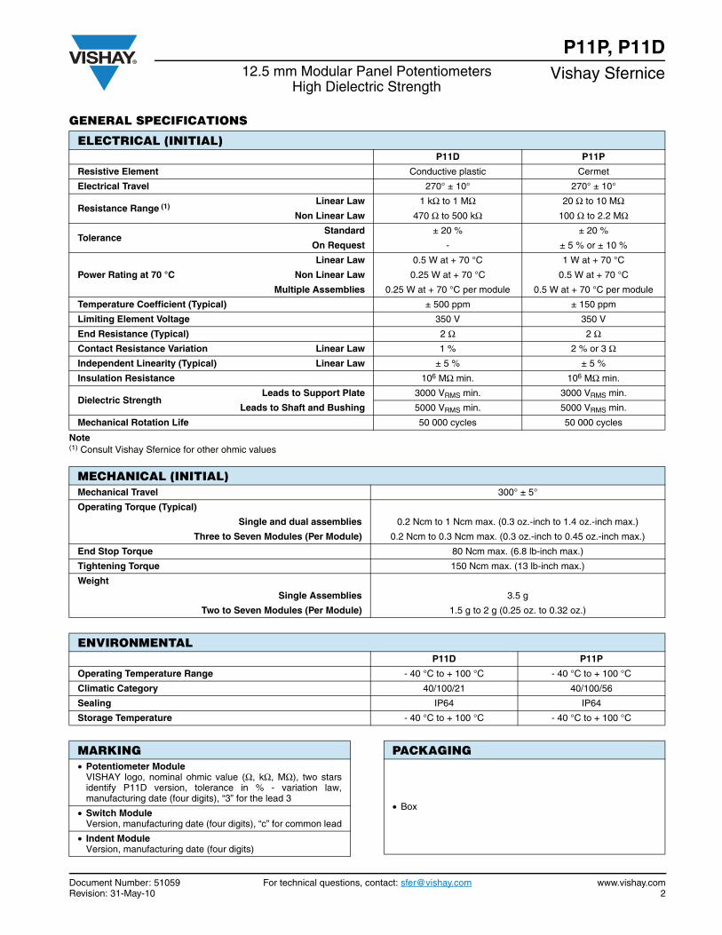
GENERAL SPECIFICATIONS
Note(1) Consult Vishay Sfernice for other ohmic values
ELECTRICAL (INITIAL)P11D P11P
Resistive Element Conductive plastic Cermet
Electrical Travel 270° ± 10° 270° ± 10°
Resistance Range (1)Linear Law 1 kΩ to 1 MΩ 20 Ω to 10 MΩ
Non Linear Law 470 Ω to 500 kΩ 100 Ω to 2.2 MΩ
ToleranceStandard ± 20 % ± 20 %
On Request - ± 5 % or ± 10 %
Power Rating at 70 °C
Linear Law 0.5 W at + 70 °C 1 W at + 70 °C
Non Linear Law 0.25 W at + 70 °C 0.5 W at + 70 °C
Multiple Assemblies 0.25 W at + 70 °C per module 0.5 W at + 70 °C per module
Temperature Coefficient (Typical) ± 500 ppm ± 150 ppm
Limiting Element Voltage 350 V 350 V
End Resistance (Typical) 2 Ω 2 ΩContact Resistance Variation Linear Law 1 % 2 % or 3 ΩIndependent Linearity (Typical) Linear Law ± 5 % ± 5 %
Insulation Resistance 106 MΩ min. 106 MΩ min.
Dielectric StrengthLeads to Support Plate 3000 VRMS min. 3000 VRMS min.
Leads to Shaft and Bushing 5000 VRMS min. 5000 VRMS min.
Mechanical Rotation Life 50 000 cycles 50 000 cycles
MECHANICAL (INITIAL)Mechanical Travel 300° ± 5°
Operating Torque (Typical)
Single and dual assemblies 0.2 Ncm to 1 Ncm max. (0.3 oz.-inch to 1.4 oz.-inch max.)
Three to Seven Modules (Per Module) 0.2 Ncm to 0.3 Ncm max. (0.3 oz.-inch to 0.45 oz.-inch max.)
End Stop Torque 80 Ncm max. (6.8 lb-inch max.)
Tightening Torque 150 Ncm max. (13 lb-inch max.)
Weight
Single Assemblies 3.5 g
Two to Seven Modules (Per Module) 1.5 g to 2 g (0.25 oz. to 0.32 oz.)
ENVIRONMENTALP11D P11P
Operating Temperature Range - 40 °C to + 100 °C - 40 °C to + 100 °C
Climatic Category 40/100/21 40/100/56
Sealing IP64 IP64
Storage Temperature - 40 °C to + 100 °C - 40 °C to + 100 °C
MARKING• Potentiometer Module
VISHAY logo, nominal ohmic value (Ω, kΩ, MΩ), two starsidentify P11D version, tolerance in % - variation law,manufacturing date (four digits), “3” for the lead 3
• Switch ModuleVersion, manufacturing date (four digits), “c” for common lead
• Indent ModuleVersion, manufacturing date (four digits)
PACKAGING
• Box
www.vishay.com For technical questions, contact: [email protected] Document Number: 510593 Revision: 31-May-10
P11P, P11DVishay Sfernice 12.5 mm Modular Panel Potentiometers
High Dielectric Strength
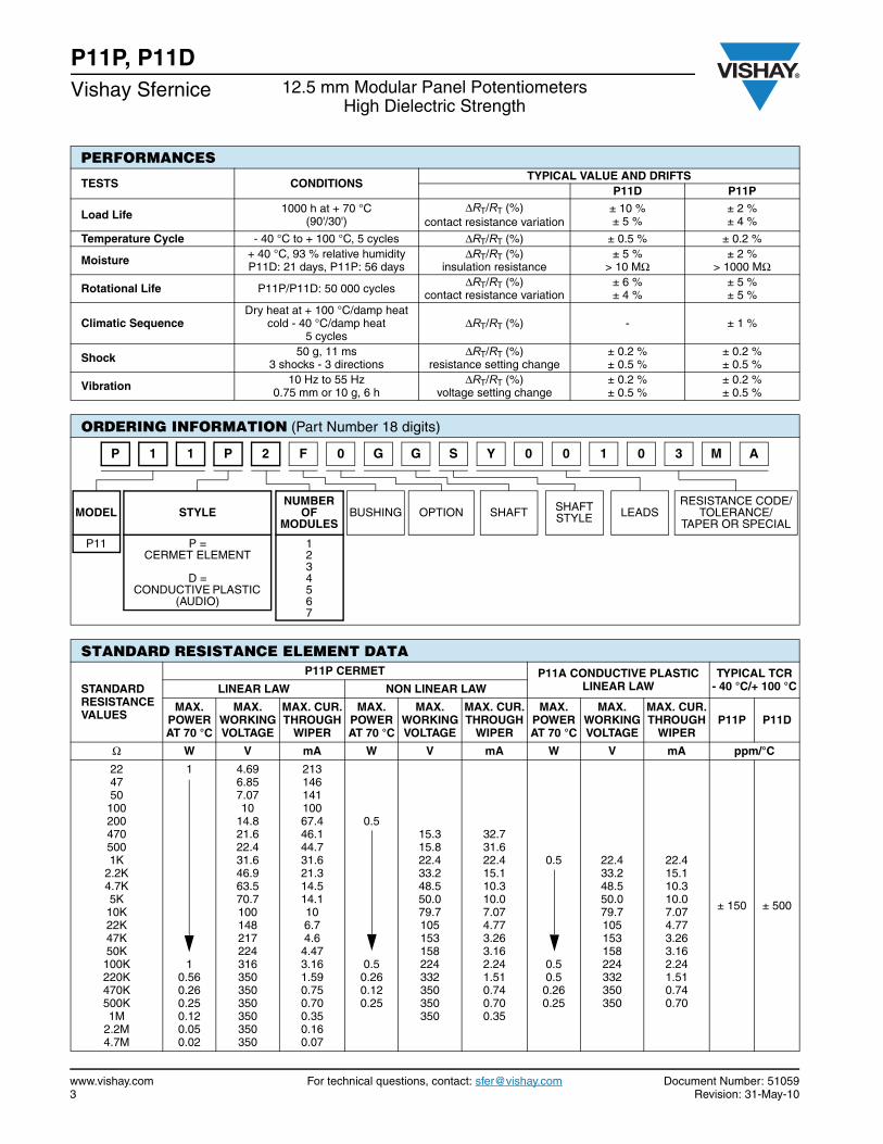
PERFORMANCES
TESTS CONDITIONSTYPICAL VALUE AND DRIFTS
P11D P11P
Load Life 1000 h at + 70 °C(90'/30')
ΔRT/RT (%)contact resistance variation
± 10 %± 5 %
± 2 %± 4 %
Temperature Cycle - 40 °C to + 100 °C, 5 cycles ΔRT/RT (%) ± 0.5 % ± 0.2 %
Moisture + 40 °C, 93 % relative humidityP11D: 21 days, P11P: 56 days
ΔRT/RT (%)insulation resistance
± 5 %> 10 MΩ
± 2 %> 1000 MΩ
Rotational Life P11P/P11D: 50 000 cycles ΔRT/RT (%)contact resistance variation
± 6 %± 4 %
± 5 %± 5 %
Climatic SequenceDry heat at + 100 °C/damp heat
cold - 40 °C/damp heat5 cycles
ΔRT/RT (%) - ± 1 %
Shock 50 g, 11 ms3 shocks - 3 directions
ΔRT/RT (%)resistance setting change
± 0.2 %± 0.5 %
± 0.2 %± 0.5 %
Vibration 10 Hz to 55 Hz0.75 mm or 10 g, 6 h
ΔRT/RT (%)voltage setting change
± 0.2 %± 0.5 %
± 0.2 %± 0.5 %
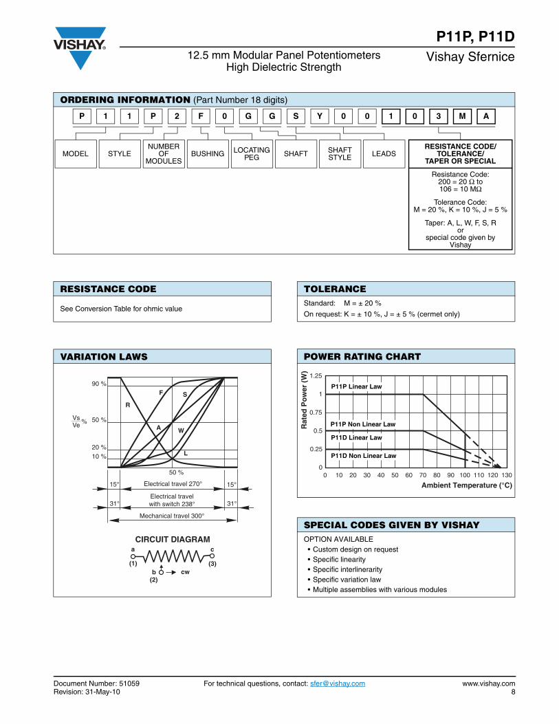
ORDERING INFORMATION (Part Number 18 digits)
MODEL STYLENUMBER
OFMODULES
BUSHING OPTION SHAFT SHAFT STYLE LEADS
RESISTANCE CODE/TOLERANCE/
TAPER OR SPECIAL
P11 P = CERMET ELEMENT
D = CONDUCTIVE PLASTIC
(AUDIO)
1234567
STANDARD RESISTANCE ELEMENT DATA
STANDARDRESISTANCEVALUES
P11P CERMET P11A CONDUCTIVE PLASTICLINEAR LAW
TYPICAL TCR- 40 °C/+ 100 °CLINEAR LAW NON LINEAR LAW
MAX.POWERAT 70 °C
MAX.WORKINGVOLTAGE
MAX. CUR.THROUGH
WIPER
MAX.POWERAT 70 °C
MAX.WORKINGVOLTAGE
MAX. CUR.THROUGH
WIPER
MAX.POWERAT 70 °C
MAX.WORKINGVOLTAGE
MAX. CUR.THROUGH
WIPERP11P P11D
Ω W V mA W V mA W V mA ppm/°C
224750
1002004705001K
2.2K4.7K5K
10K22K47K50K
100K220K470K500K1M
2.2M4.7M
1
10.560.260.250.120.050.02
4.696.857.0710
14.821.622.431.646.963.570.7100148217224316350350350350350350
21314614110067.446.144.731.621.314.514.1106.74.6
4.473.161.590.750.700.350.160.07
0.5
0.50.260.120.25
15.315.822.433.248.550.079.7105153158224332350350350
32.731.622.415.110.310.07.074.773.263.162.241.510.740.700.35
0.5
0.50.5
0.260.25
22.433.248.550.079.7105153158224332350350
22.415.110.310.07.074.773.263.162.241.510.740.70
± 150 ± 500
2 F 0 G G S Y 0 0 M1P P1 0 1 3 A
Document Number: 51059 For technical questions, contact: [email protected] www.vishay.comRevision: 31-May-10 4
P11P, P11D12.5 mm Modular Panel Potentiometers
High Dielectric StrengthVishay Sfernice
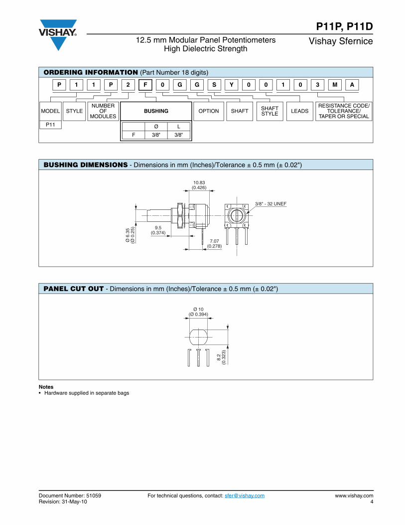
Notes• Hardware supplied in separate bags
ORDERING INFORMATION (Part Number 18 digits)
MODEL STYLENUMBER
OFMODULES
BUSHING OPTION SHAFT SHAFT STYLE LEADS
RESISTANCE CODE/TOLERANCE/
TAPER OR SPECIAL
P11 Ø L
F 3/8" 3/8"
BUSHING DIMENSIONS - Dimensions in mm (Inches)/Tolerance ± 0.5 mm (± 0.02")
PANEL CUT OUT - Dimensions in mm (Inches)/Tolerance ± 0.5 mm (± 0.02")
10.83(0.426)
7.07(0.278)
9.5(0.374)
3/8" - 32 UNEF
Ø 6
.35
(Ø 0
.25)
Ø 10(Ø 0.394)
8.2
(0.3
23)
2 F 0 G G S Y 0 0 M1P P1 0 1 3 A

www.vishay.com For technical questions, contact: [email protected] Document Number: 510595 Revision: 31-May-10
P11P, P11DVishay Sfernice 12.5 mm Modular Panel Potentiometers
High Dielectric Strength
Note
• Locating pegs and panel o ring are supplied in separate bags with nuts and washers
ORDERING INFORMATION (Part Number 18 digits)
MODEL STYLENUMBER
OFMODULES
BUSHING OPTION SHAFT SHAFT STYLE LEADS
RESISTANCE CODE/TOLERANCE/
TAPER OR SPECIAL
Location Pegs:A = Ø = 2 L = 6.2B = Ø = 2 L = 7.75C = Ø = 3.5 L = 13.50 = Without peg
Sealed Version:P = Panel and
shaft sealed
LOCATING PEGS (Anti-Rotation Lug)
The locating peg is provided by a plate mounted on the bushingand positioned by the module sides. Four set positions areavailable, clock face orientation: 12, 3, 6, 9. CODE Ø d (mm) L (mm)
EFFECTIVE HIGH PEG
Bushings have a double flat. When panel mounting holes havebeen punched accordingly, an anti-rotation lug is notnecessary.
A 2 6.2 0.7
B 2 7.75 0.7
C 3.5 13.5 1.1
PANEL AND SHAFT SEALED
O ring plate can not be used with locating pegs
12
L
3
6 Ø D
9
Ø d
8.3(0.326)
8.3(0.327)
2 F 0 G G S Y 0 0 M1P P1 0 1 3 A
Document Number: 51059 For technical questions, contact: [email protected] www.vishay.comRevision: 31-May-10 6
P11P, P11D12.5 mm Modular Panel Potentiometers
High Dielectric StrengthVishay Sfernice
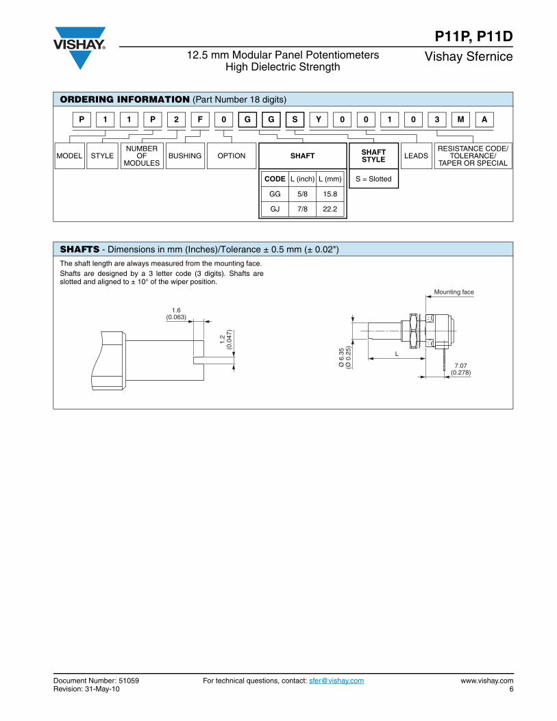
ORDERING INFORMATION (Part Number 18 digits)
MODEL STYLENUMBER
OFMODULES
BUSHING OPTION SHAFT SHAFT STYLE LEADS
RESISTANCE CODE/TOLERANCE/
TAPER OR SPECIAL
CODE L (inch) L (mm) S = Slotted
GG 5/8 15.8
GJ 7/8 22.2
SHAFTS - Dimensions in mm (Inches)/Tolerance ± 0.5 mm (± 0.02")
The shaft length are always measured from the mounting face.Shafts are designed by a 3 letter code (3 digits). Shafts areslotted and aligned to ± 10° of the wiper position.
Mounting face
7.07(0.278)
L
Ø 6
.35
(Ø 0
.25)
1.6(0.063)
1.2
(0.0
47)
2 F 0 G G S Y 0 0 M1P P1 0 1 3 A
www.vishay.com For technical questions, contact: [email protected] Document Number: 510597 Revision: 31-May-10
P11P, P11DVishay Sfernice 12.5 mm Modular Panel Potentiometers
High Dielectric Strength
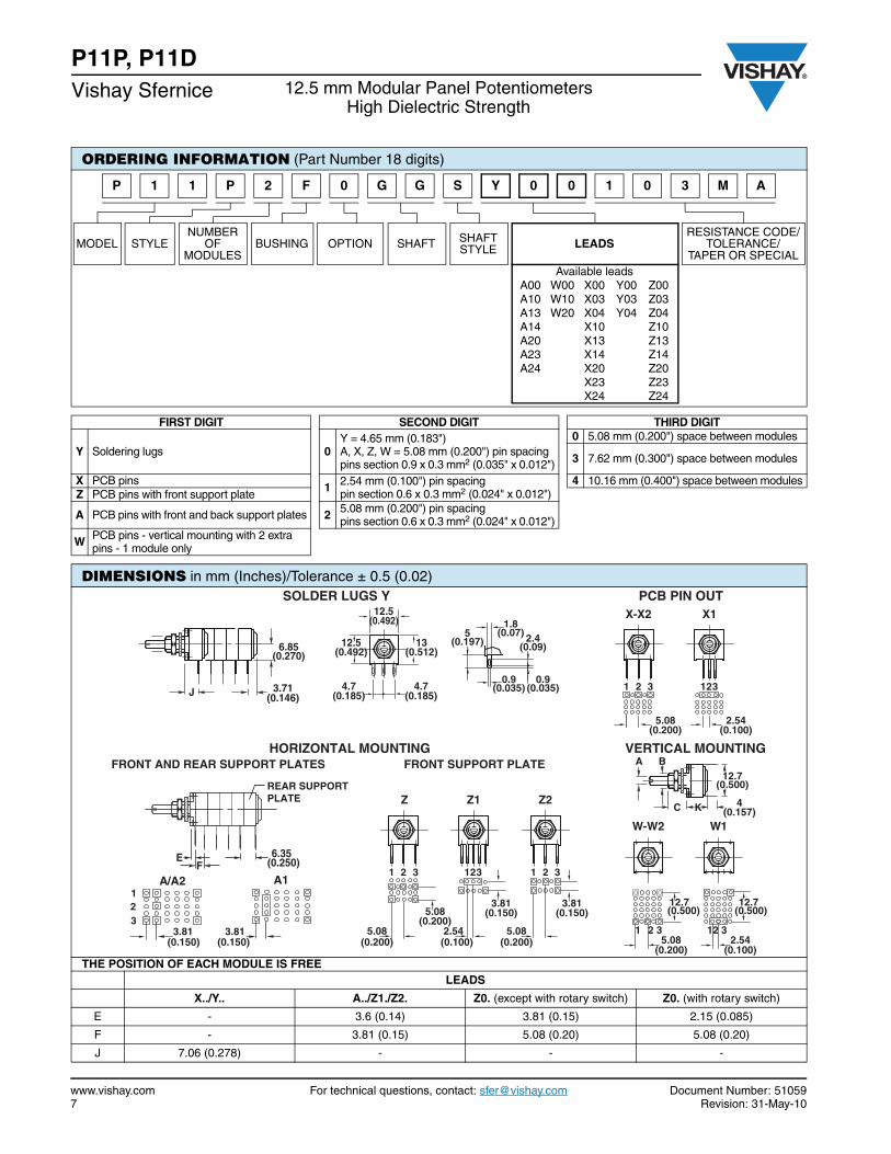
ORDERING INFORMATION (Part Number 18 digits)
MODEL STYLENUMBER
OFMODULES
BUSHING OPTION SHAFT SHAFT STYLE LEADS
RESISTANCE CODE/TOLERANCE/
TAPER OR SPECIALAvailable leads
A00 W00 X00 Y00 Z00A10 W10 X03 Y03 Z03A13 W20 X04 Y04 Z04A14 X10 Z10A20 X13 Z13A23 X14 Z14A24 X20 Z20
X23 Z23X24 Z24
FIRST DIGIT SECOND DIGIT THIRD DIGIT
Y Soldering lugs 0Y = 4.65 mm (0.183")A, X, Z, W = 5.08 mm (0.200") pin spacing pins section 0.9 x 0.3 mm2 (0.035" x 0.012")
0 5.08 mm (0.200") space between modules
3 7.62 mm (0.300") space between modules
X PCB pins 1 2.54 mm (0.100") pin spacingpin section 0.6 x 0.3 mm2 (0.024" x 0.012")
4 10.16 mm (0.400") space between modulesZ PCB pins with front support plate
A PCB pins with front and back support plates 2 5.08 mm (0.200") pin spacingpins section 0.6 x 0.3 mm2 (0.024" x 0.012")
W PCB pins - vertical mounting with 2 extra pins - 1 module only
DIMENSIONS in mm (Inches)/Tolerance ± 0.5 (0.02)
THE POSITION OF EACH MODULE IS FREELEADS
X../Y.. A../Z1./Z2. Z0. (except with rotary switch) Z0. (with rotary switch)
E - 3.6 (0.14) 3.81 (0.15) 2.15 (0.085)
F - 3.81 (0.15) 5.08 (0.20) 5.08 (0.20)
J 7.06 (0.278) - - -
3.71(0.146)
6.85(0.270)
J
13(0.512)
4.7(0.185)
12.5(0.492)
12.5(0.492)
4.7(0.185)
2.4(0.09)
1.8(0.07)5
(0.197)
0.9(0.035)
0.9(0.035)
SOLDER LUGS Y
1
2.54(0.100)
5.08(0.200)
X12X-X
2 3 123
PCB PIN OUT
HORIZONTAL MOUNTING
EF
6.35(0.250)
321
A/A2
(0.150) 3.81
(0.150)
A1
3.81
FRONT AND REAR SUPPORT PLATES FRONT SUPPORT PLATE
2.54(0.100)
5.08(0.200)
3.81(0.150)
5.08(0.200)
5.08(0.200)
3.81(0.150)
2Z1ZZ
1 2 3 123 1 2 3
VERTICAL MOUNTINGA B
C K 4(0.157)
12.7(0.500)
12.7(0.500)
5.08(0.200)
2.54(0.100)
12.7(0.500)
W-W2
1 2 3
W1
12 3
REAR SUPPORTPLATE
2 F 0 G G S Y 0 0 M1P P1 0 1 3 A
Document Number: 51059 For technical questions, contact: [email protected] www.vishay.comRevision: 31-May-10 8
P11P, P11D12.5 mm Modular Panel Potentiometers
High Dielectric StrengthVishay Sfernice
ORDERING INFORMATION (Part Number 18 digits)
MODEL STYLENUMBER
OFMODULES
BUSHING LOCATINGPEG SHAFT SHAFT
STYLE LEADSRESISTANCE CODE/
TOLERANCE/TAPER OR SPECIAL
Resistance Code:200 = 20 Ω to106 = 10 MΩ
Tolerance Code:M = 20 %, K = 10 %, J = 5 %
Taper: A, L, W, F, S, Ror
special code given byVishay
RESISTANCE CODE
See Conversion Table for ohmic value
VARIATION LAWS
a c
b cw(2)
(3)(1)
CIRCUIT DIAGRAM
R
F S
W
L
A
90 %
50 %
20 %10 %
Vs %Ve
Mechanical travel 300°
°13°13Electrical travelwith switch 238°
15°15° Electrical travel 270°
50 %
TOLERANCEStandard: M = ± 20 %
On request: K = ± 10 %, J = ± 5 % (cermet only)
POWER RATING CHART
SPECIAL CODES GIVEN BY VISHAYOPTION AVAILABLE• Custom design on request• Specific linearity• Specific interlinerarity• Specific variation law• Multiple assemblies with various modules
1307060504030201000
1
Ambient Temperature (°C)
Rat
ed P
ow
er (
W)
1201101009080
0.5
P11P Linear Law
P11P Non Linear Law
P11D Linear Law
0.25P11D Non Linear Law
0.75
1.25
2 F 0 G G S Y 0 0 M1P P1 0 1 3 A
www.vishay.com For technical questions, contact: [email protected] Document Number: 510599 Revision: 31-May-10
P11P, P11DVishay Sfernice 12.5 mm Modular Panel Potentiometers
High Dielectric Strength
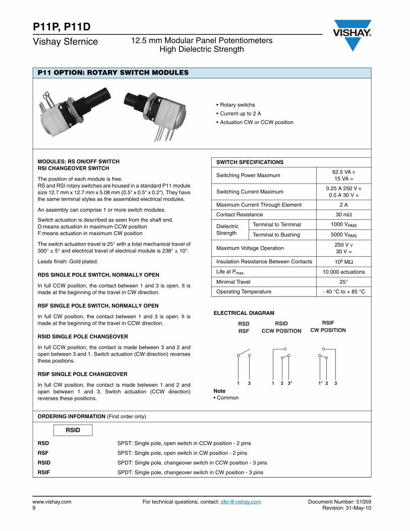
P11 OPTION: ROTARY SWITCH MODULES
• Rotary switchs
• Current up to 2 A
• Actuation CW or CCW position
MODULES: RS ON/OFF SWITCHRSI CHANGEOVER SWITCH
The position of each module is free.RS and RSI rotary switches are housed in a standard P11 modulesize 12.7 mm x 12.7 mm x 5.08 mm (0.5" x 0.5" x 0.2"). They havethe same terminal styles as the assembled electrical modules.
An assembly can comprise 1 or more switch modules.
Switch actuation is described as seen from the shaft end.D:means actuation in maximum CCW positionF:means actuation in maximum CW position
The switch actuation travel is 25° with a total mechanical travel of300° ± 5° and electrical travel of electrical module is 238° ± 10°.
Leads finish: Gold plated.
RDS SINGLE POLE SWITCH, NORMALLY OPEN
In full CCW position, the contact between 1 and 3 is open. It ismade at the beginning of the travel in CW direction.
RSF SINGLE POLE SWITCH, NORMALLY OPEN
In full CW position, the contact between 1 and 3 is open. It ismade at the beginning of the travel in CCW direction.
RSID SINGLE POLE CHANGEOVER
In full CCW position, the contact is made between 3 and 2 andopen between 3 and 1. Switch actuation (CW direction) reversesthese positions.
RSIF SINGLE POLE CHANGEOVER
In full CW position, the contact is made between 1 and 2 andopen between 1 and 3. Switch actuation (CCW direction)reverses these positions.
SWITCH SPECIFICATIONS
Switching Power Maximum62.5 VA ν15 VA =
Switching Current Maximum0.25 A 250 V ν0.5 A 30 V =
Maximum Current Through Element 2 A
Contact Resistance 30 mΩ
Dielectric Strength
Terminal to Terminal 1000 VRMS
Terminal to Bushing 5000 VRMS
Maximum Voltage Operation250 V ν30 V =
Insulation Resistance Between Contacts 106 MΩ
Life at Pmax. 10 000 actuations
Minimal Travel 25°
Operating Temperature - 40 °C to + 85 °C
ELECTRICAL DIAGRAM
Note• Common
ORDERING INFORMATION (First order only)
RSD SPST: Single pole, open switch in CCW position - 2 pins
RSF SPST: Single pole, open switch in CW position - 2 pins
RSID SPDT: Single pole, changeover switch in CCW position - 3 pins
RSIF SPDT: Single pole, changeover switch in CW position - 3 pins
RSIFCW POSITION
1* 32
RSIDCCW POSITION
1 3*2
RSDRSF
1 3
RSID
Document Number: 51059 For technical questions, contact: [email protected] www.vishay.comRevision: 31-May-10 10
P11P, P11D12.5 mm Modular Panel Potentiometers
High Dielectric StrengthVishay Sfernice
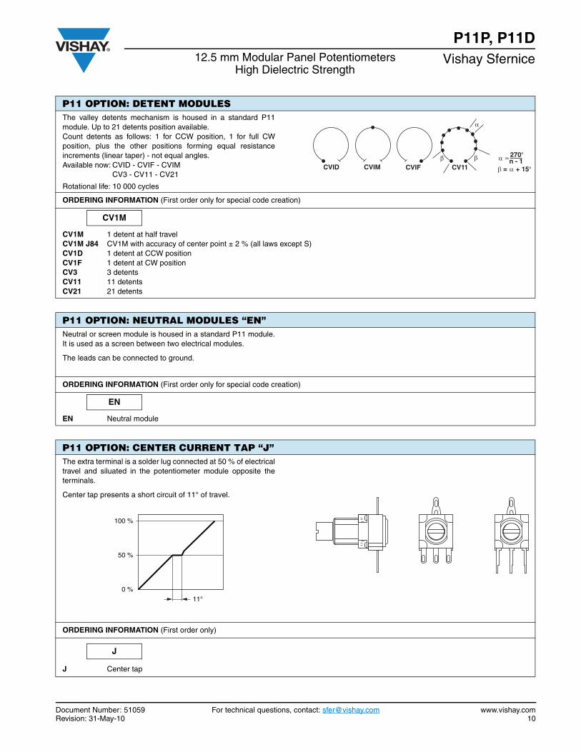
P11 OPTION: DETENT MODULESThe valley detents mechanism is housed in a standard P11module. Up to 21 detents position available.Count detents as follows: 1 for CCW position, 1 for full CWposition, plus the other positions forming equal resistanceincrements (linear taper) - not equal angles.Available now: CVID - CVIF - CVIM
CV3 - CV11 - CV21
Rotational life: 10 000 cycles
ORDERING INFORMATION (First order only for special code creation)
CV1M 1 detent at half travelCV1M J84 CV1M with accuracy of center point ± 2 % (all laws except S)CV1D 1 detent at CCW positionCV1F 1 detent at CW positionCV3 3 detentsCV11 11 detentsCV21 21 detents
P11 OPTION: NEUTRAL MODULES “EN”Neutral or screen module is housed in a standard P11 module.It is used as a screen between two electrical modules.
The leads can be connected to ground.
ORDERING INFORMATION (First order only for special code creation)
EN Neutral module
P11 OPTION: CENTER CURRENT TAP “J”The extra terminal is a solder lug connected at 50 % of electricaltravel and siluated in the potentiometer module opposite theterminals.
Center tap presents a short circuit of 11° of travel.
ORDERING INFORMATION (First order only)
J Center tap
CVID CVIM CVIF CV1 1β β α = 270 °
n - 1β = α + 15 °
α
100 %
50 %
0 %
11°
CV1M
EN
J

www.vishay.com For technical questions, contact: [email protected] Document Number: 5105911 Revision: 31-May-10
P11P, P11DVishay Sfernice 12.5 mm Modular Panel Potentiometers
High Dielectric Strength
P11 OPTION: SPECIAL LINEARITY - CONFORMITYThe independent linearity (conformity for the non linear laws) isthe maximum gap ΔV between the actual variation curve and thetheorical variation curve the nearest to it. The linearity and theconformity are expressed in percentage of the total appliedvoltage E
They are measured over 90 % of actual electrical travel(centered).On request linearity can be guaranteed in linear law.
ORDERING INFORMATION (First order only)
J123 Independent linearity ± 3 % (linear law)J145 Independent linearity ± 2 % (linear law)
For other request, contact us.
P11 OPTION: SPECIAL INTERLINEARITY - INTERCONFORMITYIt is the maximum deviation between the actual voltage outputsof 2 or more pot modules in the same assembly. It is expressedas a percentage of the total applied voltage, or in dB attenuation.
Interlinearity is measured between 2 pot modules, over 10 to90 % of the attenuation.
The interlinearity or interconformity is expressed as apercentage of the total applied voltage:
Or in decibels by comparison between outputs V1 and V2
ORDERING INFORMATION (First order only)
J44 Interlinearity ± 2 % (linear law) For other request, contact us.
VE
V
Limits oflinearity test
Effective electrical travel
linearity conformity± ΔVmax.
E-----------------------=
VE
C
V1V2
Limits of testEffective electrical travel
V1 V2
I % CE
-------=
I dB 20 log V1
V2------=
J123
J44
Document Number: 51059 For technical questions, contact: [email protected] www.vishay.comRevision: 31-May-10 12
P11P, P11D12.5 mm Modular Panel Potentiometers
High Dielectric StrengthVishay Sfernice
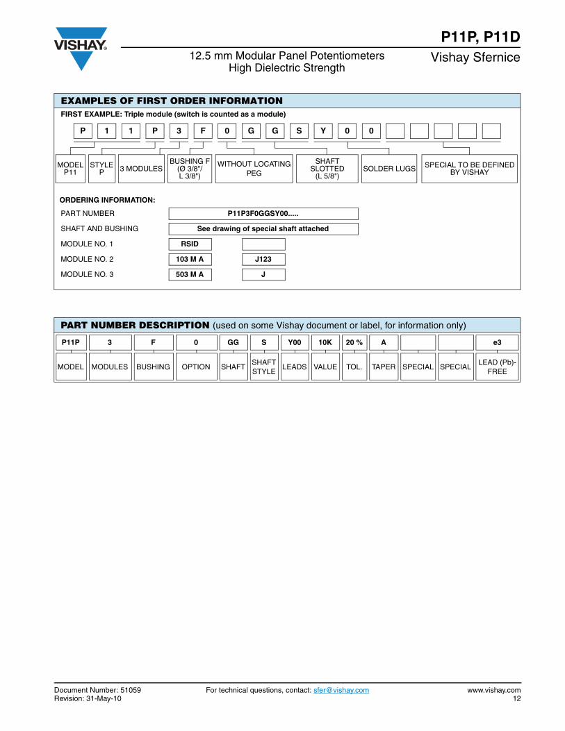
EXAMPLES OF FIRST ORDER INFORMATIONFIRST EXAMPLE: Triple module (switch is counted as a module)
MODEL P11
STYLEP 3 MODULES
BUSHING F(Ø 3/8"/L 3/8")
WITHOUT LOCATINGPEG
SHAFT SLOTTED
(L 5/8")SOLDER LUGS SPECIAL TO BE DEFINED
BY VISHAY
ORDERING INFORMATION:
PART NUMBER P11P3F0GGSY00.....
SHAFT AND BUSHING See drawing of special shaft attached
MODULE NO. 1 RSID
MODULE NO. 2 103 M A J123
MODULE NO. 3 503 M A J
PART NUMBER DESCRIPTION (used on some Vishay document or label, for information only)
P11P 3 F 0 GG S Y00 10K 20 % A e3
MODEL MODULES BUSHING OPTION SHAFTSHAFTSTYLE
LEADS VALUE TOL. TAPER SPECIAL SPECIALLEAD (Pb)-
FREE
3 F 0 G G S Y 01P P1 0
Document Number: 91000 www.vishay.comRevision: 18-Jul-08 1
Disclaimer
Legal Disclaimer NoticeVishay
All product specifications and data are subject to change without notice.
Vishay Intertechnology, Inc., its affiliates, agents, and employees, and all persons acting on its or their behalf(collectively, “Vishay”), disclaim any and all liability for any errors, inaccuracies or incompleteness contained hereinor in any other disclosure relating to any product.
Vishay disclaims any and all liability arising out of the use or application of any product described herein or of anyinformation provided herein to the maximum extent permitted by law. The product specifications do not expand orotherwise modify Vishay’s terms and conditions of purchase, including but not limited to the warranty expressedtherein, which apply to these products.
No license, express or implied, by estoppel or otherwise, to any intellectual property rights is granted by thisdocument or by any conduct of Vishay.
The products shown herein are not designed for use in medical, life-saving, or life-sustaining applications unlessotherwise expressly indicated. Customers using or selling Vishay products not expressly indicated for use in suchapplications do so entirely at their own risk and agree to fully indemnify Vishay for any damages arising or resultingfrom such use or sale. Please contact authorized Vishay personnel to obtain written terms and conditions regardingproducts designed for such applications.
Product names and markings noted herein may be trademarks of their respective owners.
![AU OPTRONICS CORPORATION - display-lcd.cz · PDF fileCCFL Current ICFL - 7 [mA] rms Note 1,2 4.3 Absolute Ratings of Environment Item Symbol Min Max Unit ... Symble Parameter Min Typ](https://img.dokumen.tips/doc/110x75/5abbe9717f8b9a441d8d654b/au-optronics-corporation-display-lcdcz-current-icfl-7-ma-rms-note-12-43.jpg)


![Datasheet - DataDisplay Group · PDF fileDatasheet AUO. UP-02-158. ... 1.7 [A] rms Note 1, 2 4.3 Absolute Ratings of Environment Item Symbol Min. Max. Unit ... Symble Parameter Min](https://img.dokumen.tips/doc/110x75/5abbe9717f8b9a441d8d6536/datasheet-datadisplay-group-auo-up-02-158-17-a-rms-note-1-2-43-absolute.jpg)