Embed Size (px)
Citation preview
8/18/2019 121 Life Cycle Assessmnet of Solid Waste Management - Copy
http://slidepdf.com/reader/full/121-life-cycle-assessmnet-of-solid-waste-management-copy 1/35
EPA Cooperative Agreement 832052
July 1995
Life-Cycle Study of
Municipal Solid Waste Management
System Description
Prepared by
Morton A. Barlaz
Ranji Ranjithan
North Carolina State University
Raleigh, NC 27695
and
Keith A. WeitzSubba R. Nishtala
Research Triangle Institute
Research Triangle Park, NC 27709

8/18/2019 121 Life Cycle Assessmnet of Solid Waste Management - Copy
http://slidepdf.com/reader/full/121-life-cycle-assessmnet-of-solid-waste-management-copy 2/35
ii
Notice
The information contained in this report has been developed as part of ongoing research funded
by the U.S. Environmental Protection Agency under Cooperative Agreement No. CR823052 withthe Research Triangle Institute. The results from this study are not intended to be used to judge
which materials or products are environmentally preferable. Use of the methods or data presented
in this report does not constitute endorsement or recommendation for use. This report is subject
to review and modification prior to conclusion of the research. Mention of trade names or
commercial products does not constitute endorsement or recommendation.
8/18/2019 121 Life Cycle Assessmnet of Solid Waste Management - Copy
http://slidepdf.com/reader/full/121-life-cycle-assessmnet-of-solid-waste-management-copy 3/35
iii
Abstract
Communities throughout the United States are struggling to develop efficient and cost-effective
plans for managing their municipal solid waste (MSW). In the past, waste management systems
consisted primarily of waste collection and disposal at a local landfill. Today's MSW managementsystems often are complex and highly integrated systems that might include materials collection,
materials recovery, composting, combustion, and other processing steps. Communities now must
make complex decisions involving tradeoffs between environmental performance and cost, which
must be carefully analyzed for these integrated systems.
Despite the movement toward integrated systems, many of the existing techniques for analyzing
the environmental and economic performance of MSW management systems focus on the
individual operations in isolation rather than as a dynamic part of an integrated system. To
properly account for all of the environmental effects associated with integrated MSW
management systems, planners must have tools that allow them to examine factors outside of the
traditional MSW management framework of activities occurring from the point of wastecollection to final disposal. This requires an examination of the Aupstream@ changes in resource
use and pollutant generation from raw materials acquisition and manufacturing operations. These
upstream changes can be captured by taking a life cycle approach to MSW management.
The U.S. Environmental Protection Agency's (EPA=s) Office of Research and Development, Air
Pollution Prevention and Control Division, and with cofunding from the U.S. Department of
Energy, is working to apply life cycle concepts and tools to the analysis of MSW management
systems in the United States. The project began in August of 1994 and is expected to be
completed in 1999. The research team for this project includes life cycle assessment (LCA) and
MSW experts from Research Triangle Institute (RTI), North Carolina State University, the
University of Wisconsin-Madison, Franklin Associates, and Roy F. Weston. In addition, groupsof internal advisors and external stakeholders are active participants in this unique forum. The
information and tools resulting from this research will help solid waste practitioners identify
integrated MSW management strategies that minimize both environmental burdens and cost.
This document describes the overall system that will be used to conduct the life-cycle and cost
analysis of integrated MSW management alternatives. The system is divided into a number of
distinct solid waste management processes including include waste generation, source reduction,
collection and transfer, materials recovery, composting, combustion, refuse-derived fuel
production and combustion, anaerobic digestion, and burial. The system also includes processes
involved with manufacturing products from virgin material and remanufacturing products from
recycled materials.

8/18/2019 121 Life Cycle Assessmnet of Solid Waste Management - Copy
http://slidepdf.com/reader/full/121-life-cycle-assessmnet-of-solid-waste-management-copy 4/35
iv
Table of Contents
Notice ......................................................................................................................................... ii
Abstract ..................................................................................................................................... iii
List of Figures............................................................................................................................. vList of Tables ............................................................................................................................. vi
Abbreviations and Symbols........................................................................................................ vii
Section 1 Introduction .........................................................................................................1
Section 2 Waste Generation.................................................................................................5
Section 3 Waste Composition ..............................................................................................5
Section 4 In-Home Recyclables Separation..........................................................................7
Section 5 Waste Collection..................................................................................................7
5.1 Collection of Residential Refuse and Recyclables ......................................8
5.2 Collection of Multi-Family Dwelling Refuse and Recyclables ....................9
5.3 Collection of Commercial Waste.............................................................10
Section 6 Transfer Stations................................................................................................10
Section 7 Material Recovery Facilities ............................................................................... 16
Section 8 Remanufacturing and Energy Recovery ..............................................................19
Section 9 Composting........................................................................................................22
Section 10 Waste-to-Energy Combustion ............................................................................23
Section 11 Refure Derived Fuel and Co-Combustion ...........................................................23
Section 12 Anaerobic Digestion........................................................................................... 24
Section 13 Landfills .............................................................................................................24
Section 14 Source Reduction...............................................................................................25
Section 15 Summary of System Boundaries.........................................................................26
15.1 System Boundaries for LCI.....................................................................26
15.2 System Boundaries for Cost Analysis......................................................27
References ................................................................................................................................28
8/18/2019 121 Life Cycle Assessmnet of Solid Waste Management - Copy
http://slidepdf.com/reader/full/121-life-cycle-assessmnet-of-solid-waste-management-copy 5/35
v
List of Figures
Figures Page
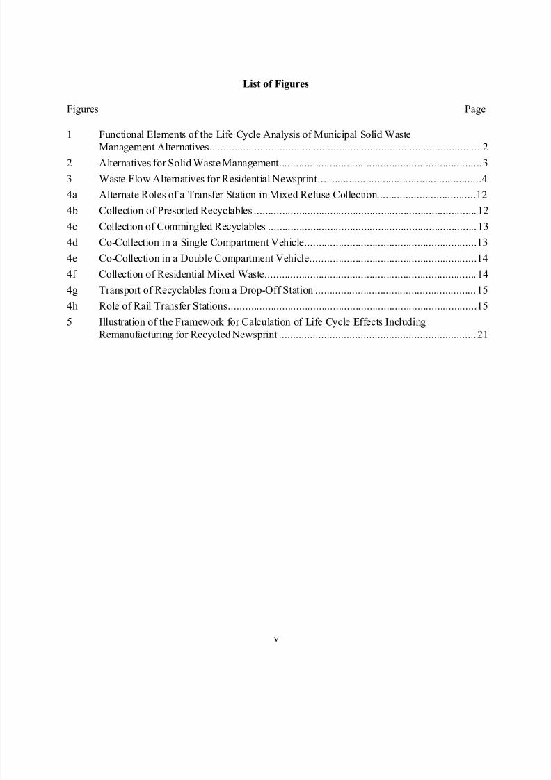
1 Functional Elements of the Life Cycle Analysis of Municipal Solid WasteManagement Alternatives.................................................................................................2
2 Alternatives for Solid Waste Management........................................................................3
3 Waste Flow Alternatives for Residential Newsprint..........................................................4
4a Alternate Roles of a Transfer Station in Mixed Refuse Collection...................................12
4b Collection of Presorted Recyclables ............................................................................... 12
4c Collection of Commingled Recyclables ..........................................................................13
4d Co-Collection in a Single Compartment Vehicle.............................................................13
4e Co-Collection in a Double Compartment Vehicle...........................................................14
4f Collection of Residential Mixed Waste........................................................................... 14
4g Transport of Recyclables from a Drop-Off Station .........................................................15
4h Role of Rail Transfer Stations........................................................................................15
5 Illustration of the Framework for Calculation of Life Cycle Effects Including
Remanufacturing for Recycled Newsprint ...................................................................... 21
8/18/2019 121 Life Cycle Assessmnet of Solid Waste Management - Copy
http://slidepdf.com/reader/full/121-life-cycle-assessmnet-of-solid-waste-management-copy 6/35
vi
List of Tables
Table Page
1 Components of MSW to Be Considered in the System.....................................................6
2 Materials Which Can Be Recycled at Each MRF Type ...................................................18
8/18/2019 121 Life Cycle Assessmnet of Solid Waste Management - Copy
http://slidepdf.com/reader/full/121-life-cycle-assessmnet-of-solid-waste-management-copy 7/35
vii
Abbreviations and Symbols
BTU British Thermal UnitEPA United States Environmental Protection Agency
FAL Franklin Associates, Limited
KWH Kilowatt Hour
LCA Life-Cycle Assessment
LCI Life-Cycle Inventory
MRF Materials Recovery Facility
MSW Municipal Solid Waste
NCSU North Carolina State University
POTW Publicly Owned Treatment Works
RCRA Resource Conservation and Recovery Act
RTI Research Triangle InstituteSETAC Society for Environmental Toxicology and Chemistry
8/18/2019 121 Life Cycle Assessmnet of Solid Waste Management - Copy
http://slidepdf.com/reader/full/121-life-cycle-assessmnet-of-solid-waste-management-copy 8/35
1
1. INTRODUCTION
The objective of this document is to describe the system and the system boundaries which will be
used to conduct the life-cycle inventory (LCI) and cost analysis of municipal solid waste (MSW)
management alternatives. This system description is a small but critical part of the overall project.
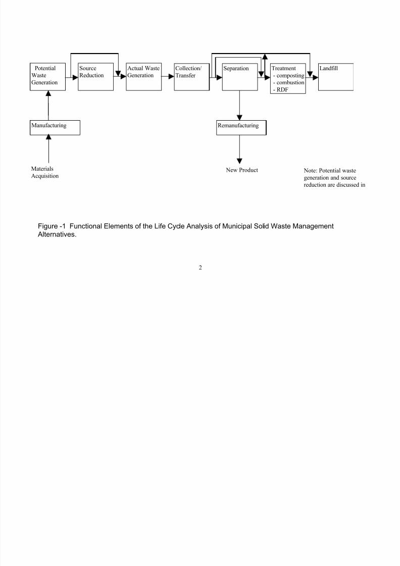
The overall system will be divided into a number of distinct solid waste management processes
linked together as illustrated in Figure 1. These processes include waste generation, source
reduction, collection and transfer, separation (materials recovery and drop-off facilities), treatment
(which may include composting, combustion or RDF production) and burial. Remanufacturing is
considered to the extent that a specific component of the waste stream is recycled. In this case,
the LCI will include energy and resource consumption and the environmental releases involved in
the remanufacturing process, as well as the energy, resources, or releases offset by virtue of using
recycled versus virgin materials.
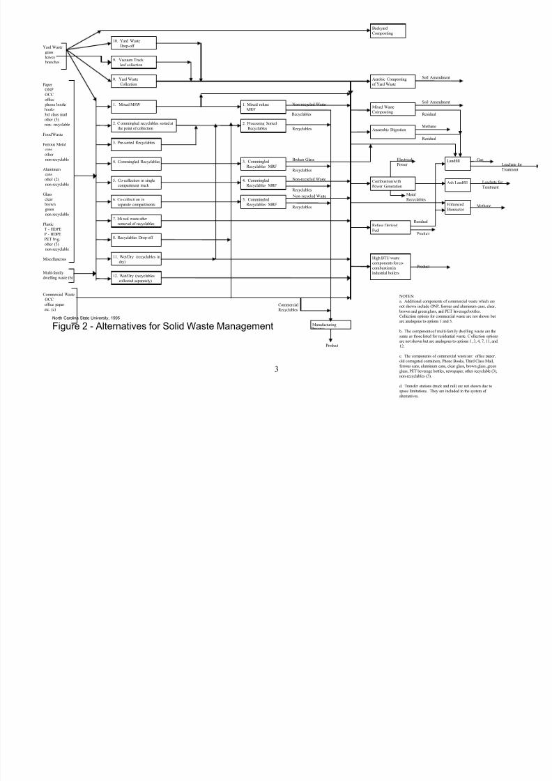
Although Figure 1 illustrates the functional elements which comprise the MSW system, the key
unit operations in the system and the manner in which waste can flow between these unit
operations are illustrated in Figure 2. As presented in Figure 2, there is a lot of interrelatedness
between the individual unit operations. For example, decisions made with respect to waste
separation influence downstream processes such as combustion. An example of waste
management alternatives for one waste component is presented in Figure 3. This figure illustrates
the possible paths for old newsprint (ONP) through the system.
In defining the solid waste management system, our objective is to be as flexible as possible.
However, given the large diversity of settings in which MSW is generated in the United States,
development of a single system definition to address all situations will be unnecessarilycomplicated. Thus, there are likely to be situations where this system definition cannot be
applied.
The ultimate products of this research will include a database and decision support tool that will
enable users to perform an LCI and cost analyses based on locality specific data on MSW
generation and management. The decision support tool will be supported by the database, which
will contain data on LCI parameters for individual solid waste management unit operations.
Work will proceed concurrently to collect the data required for analysis of site specific solid waste
management scenarios and to develop the decision support system.
This document is structured to follow the order of the functional elements as presented in Figure
1, with the exception of source reduction which is presented after landfills. The discussion of
system boundaries is summarized in the final section by which time the reader will have a more
complete understanding of the proposed system.
8/18/2019 121 Life Cycle Assessmnet of Solid Waste Management - Copy
http://slidepdf.com/reader/full/121-life-cycle-assessmnet-of-solid-waste-management-copy 9/35
2
Figure -1 Functional Elements of the Life Cycle Analysis of Municipal Solid Waste Management Alternatives.
Potential
Waste
Generation
Collection/
Transfer
Actual Waste
Generation
LandfillTreatment
- composting
- combustion
- RDF
SeparationSource
Reduction
Manufacturing Remanufacturing
Materials
Acquisition New Product Note: Potential waste
generation and source
reduction are discussed in
8/18/2019 121 Life Cycle Assessmnet of Solid Waste Management - Copy
http://slidepdf.com/reader/full/121-life-cycle-assessmnet-of-solid-waste-management-copy 10/35
3
North Carolina State University, 1995
Figure 2 - Alternatives for Solid Waste Management
Metal
Recyclables
Paper
ONP
OCC
office
phone books
books
3rd class mail
other (5)
non- recyclable
Food Waste
Ferrous Metal
cans
other
non-recyclable
Aluminum
cans
other (2)
non-recyclable
Glass
clear
brown
green
non-recyclable
Plastic
T - HDPE
P - HDPE
PET bvg.
other (5)
non-recyclable
Miscellaneous
Ash Landfill
LandfillLeachate
Treatmen
Leachate for
Treatment
Gas
Backyard
Composting
Aerobic Composting
of Yard Waste
Refuse Derived
Fuel
Combustion with
Power Generation
Electrical
Power
Product
Yard Waste
grass
leaves
branches
1. Mixed refuse
MRF
9. Vacuum Truck
leaf collection
10. Yard Waste
Drop-off
Multi-familydwelling waste (b)
Recyclables
Recyclables
Non-recycled Waste
3. Commingled
Recyclables MRF
2. Processing Sorted
Recyclables
4. Commingled
Recyclables MRF
5. Commingled
Recyclables MRF
Commercial Waste
OCC
office paper
etc. (c)
0. Yard Waste
Collection
12. Wet/Dry (recyclables
collected separately)
1. Mixed MSW
2. C ommingled recyclables sorted at
the point of collection
3. Pre-sorted Recyclables
4. Commingled Recyclables
5. Co-collection in single
compartment truck
6. Co-collecti on in
separate compartments
7. Mi xed waste after
removal of recyclables
8. Recyclables Drop-off
11. Wet/Dry (recyclables in
dry)
Anaerobic Digestion
Manufacturing
Mixed Waste
Composting
Product
High BTU waste
components for co-
combustion in
industrial boilers
Product
Soil Amendment
Soil Amendment
Residual
Residual
Methane
Broken Glass
Recyclables
Non-recycled Waste
Non-recycled Waste
Recyclables
Recyclables
Residual
Commercial
Recyclables
Enhanced
Bioreactor Methane
NOTES:
a. Additional components of commercial waste which are
not shown include ONP, ferrous and aluminum cans, clear,
brown and green glass, and PET beverage bottles.
Collection options for commercial waste are not shown but
are analogous to options 1 and 3.
b. The components of multi-family dwelling waste are the
same as those listed for residential waste. C ollection options
are not shown but are analogous to options 1, 3, 4, 7, 11, and
12.
c. The components of commercial waste are: office paper,
old corrugated containers, Phone Books, Third Class Mail,
ferrous cans, aluminum cans, clear glass, brown glass, green
glass, PET beverage bottles, newspaper, other recyclable (3),
non-recyclables (3).
d. Transfer stations (truck and rail) are not shown due to
space limitations. They are included in the system of
alternatives.

8/18/2019 121 Life Cycle Assessmnet of Solid Waste Management - Copy
http://slidepdf.com/reader/full/121-life-cycle-assessmnet-of-solid-waste-management-copy 11/35
4
North Carolina State University, 1995
Figure 3 - Waste Flow Alternatives for Residential Newsprint
Metal
Recyclables
Residential
ONP
Ash Landfill
LandfillLeachate for
Treatment
Leachate for
Treatment
Gas
Refuse Derived
Fuel
Combustion with
Power Generation
Electrical
Power
Product
1. Mixed refuse
MRF
Recyclables
Recyclables
Non-recycled Waste
3. Commingled
Recyclables MRF
2. Processing Sorted
Recyclables
4. Commingled
Recyclables MRF
5. Commingled
Recyclables MRF
12. Wet/Dry (recyclables
collected separately
1. Mixed MSW
2. C ommingled recyclables sorted at
the point of collection
3. Pre-sorted Recyclables
4. Commingled Recyclables
5. C o-collection in single
compartment truck
6. Co-collection in
separate compartments
7. Mixed waste after
removal of recyclables
8. Recyclables Drop-off
11. Wet/Dry (recyclables in
dry)
Anaerobic Digestion
Manufacturing
Mixed Waste
Composting
Product
High BTU waste
components for co-
combustion in
industrial boilers
Product
Soil Amendment
Residual
Residual
Methane
Recyclables
Recyclables
Recyclables
Residual
Enhanced
Bioreactor Methane
NOTES:
a. MRF processing for multi-family and commercial
ONP are not shown due to space limitations. They are
included in the system of alternatives.
c. Transfer stations (truck and rail) are not shown due
to space limitations. They are included in the system of
alternatives.
8/18/2019 121 Life Cycle Assessmnet of Solid Waste Management - Copy
http://slidepdf.com/reader/full/121-life-cycle-assessmnet-of-solid-waste-management-copy 12/35
5
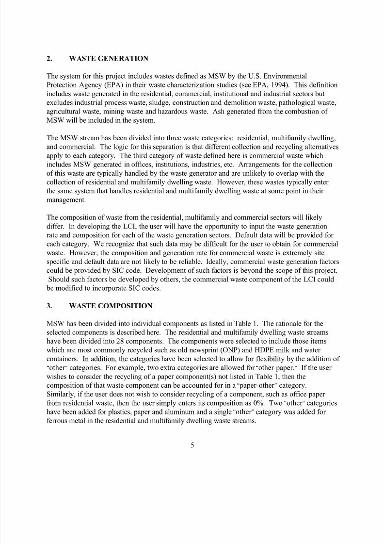
2. WASTE GENERATION
The system for this project includes wastes defined as MSW by the U.S. Environmental
Protection Agency (EPA) in their waste characterization studies (see EPA, 1994). This definition
includes waste generated in the residential, commercial, institutional and industrial sectors butexcludes industrial process waste, sludge, construction and demolition waste, pathological waste,
agricultural waste, mining waste and hazardous waste. Ash generated from the combustion of
MSW will be included in the system.
The MSW stream has been divided into three waste categories: residential, multifamily dwelling,
and commercial. The logic for this separation is that different collection and recycling alternatives
apply to each category. The third category of waste defined here is commercial waste which
includes MSW generated in offices, institutions, industries, etc. Arrangements for the collection
of this waste are typically handled by the waste generator and are unlikely to overlap with the
collection of residential and multifamily dwelling waste. However, these wastes typically enter
the same system that handles residential and multifamily dwelling waste at some point in their management.
The composition of waste from the residential, multifamily and commercial sectors will likely
differ. In developing the LCI, the user will have the opportunity to input the waste generation
rate and composition for each of the waste generation sectors. Default data will be provided for
each category. We recognize that such data may be difficult for the user to obtain for commercial
waste. However, the composition and generation rate for commercial waste is extremely site
specific and default data are not likely to be reliable. Ideally, commercial waste generation factors
could be provided by SIC code. Development of such factors is beyond the scope of this project.
Should such factors be developed by others, the commercial waste component of the LCI could
be modified to incorporate SIC codes.
3. WASTE COMPOSITION
MSW has been divided into individual components as listed in Table 1. The rationale for the
selected components is described here. The residential and multifamily dwelling waste streams
have been divided into 28 components. The components were selected to include those items
which are most commonly recycled such as old newsprint (ONP) and HDPE milk and water
containers. In addition, the categories have been selected to allow for flexibility by the addition of
Aother @ categories. For example, two extra categories are allowed for Aother paper.@ If the user
wishes to consider the recycling of a paper component(s) not listed in Table 1, then the
composition of that waste component can be accounted for in a A paper-other @ category.
Similarly, if the user does not wish to consider recycling of a component, such as office paper
from residential waste, then the user simply enters its composition as 0%. Two Aother @ categories
have been added for plastics, paper and aluminum and a single Aother @ category was added for
ferrous metal in the residential and multifamily dwelling waste streams.
8/18/2019 121 Life Cycle Assessmnet of Solid Waste Management - Copy
http://slidepdf.com/reader/full/121-life-cycle-assessmnet-of-solid-waste-management-copy 13/35
6
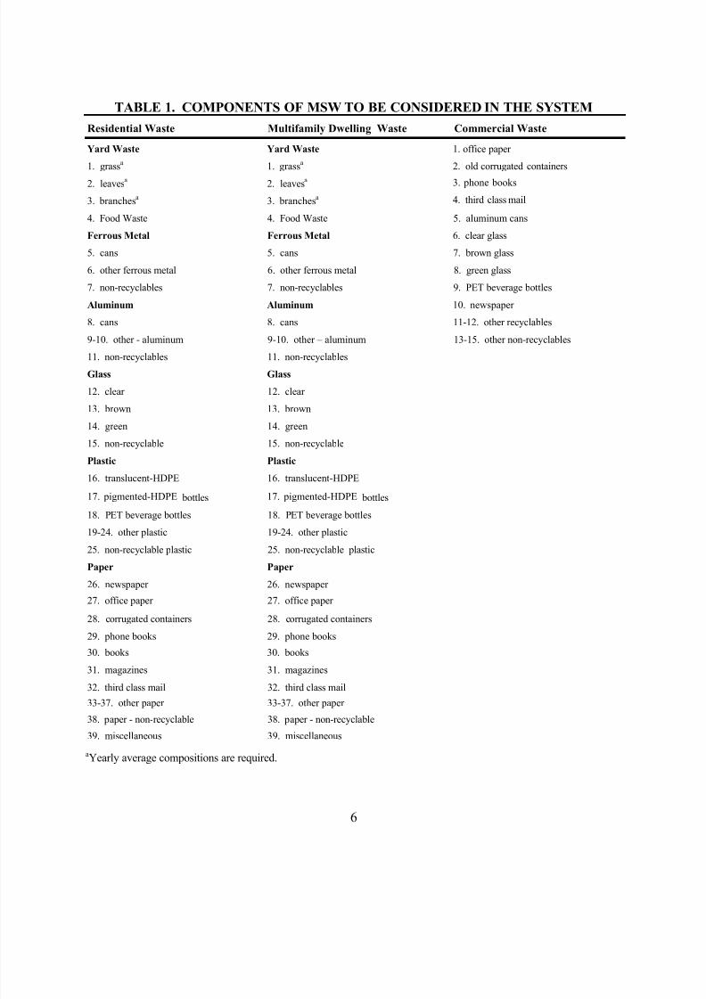
TABLE 1. COMPONENTS OF MSW TO BE CONSIDERED IN THE SYSTEM
Residential Waste Multifamily Dwelling Waste Commercial Waste
Yard Waste Yard Waste 1. office paper
1. grassa
1. grassa
2. old corrugated containers
2. leavesa
2. leavesa 3. phone books
3. branchesa
3. branchesa 4. third class mail
4. Food Waste 4. Food Waste 5. aluminum cans
Ferrous Metal Ferrous Metal 6. clear glass
5. cans 5. cans 7. brown glass
6. other ferrous metal 6. other ferrous metal 8. green glass
7. non-recyclables 7. non-recyclables 9. PET beverage bottles
Aluminum Aluminum 10. newspaper
8. cans 8. cans 11-12. other recyclables
9-10. other - aluminum 9-10. other – aluminum 13-15. other non-recyclables
11. non-recyclables 11. non-recyclables
Glass Glass
12. clear 12. clear
13. brown 13. brown
14. green 14. green
15. non-recyclable 15. non-recyclable
Plastic Plastic
16. translucent-HDPE 16. translucent-HDPE
17. pigmented-HDPE bottles 17. pigmented-HDPE bottles
18. PET beverage bottles 18. PET beverage bottles
19-24. other plastic 19-24. other plastic
25. non-recyclable plastic 25. non-recyclable plastic
Paper Paper
26. newspaper 26. newspaper
27. office paper 27. office paper
28. corrugated containers 28. corrugated containers
29. phone books 29. phone books
30. books 30. books
31. magazines 31. magazines
32. third class mail 32. third class mail
33-37. other paper 33-37. other paper
38. paper - non-recyclable 38. paper - non-recyclable
39. miscellaneous 39. miscellaneous
aYearly average compositions are required.
8/18/2019 121 Life Cycle Assessmnet of Solid Waste Management - Copy
http://slidepdf.com/reader/full/121-life-cycle-assessmnet-of-solid-waste-management-copy 14/35
7
The waste components listed in Table 1 are the same for residential and multifamily dwelling
waste. However, different compositions for each waste component may be used if desired. The
commercial waste stream has been divided into twelve components. These components include
the major recyclables in commercial waste based on national averages (office paper and old
corrugated containers (OCC)), materials which are commonly recycled (aluminum cans, PET beverage bottles, container glass and newsprint), two Aother @ categories and non-recyclables.
Although wastes are listed as individual components in Table 1, there are cases where wastes can
be grouped together. The system is mathematically defined to allow consideration of mixed color
glass recycling in addition to recycling by individual color. Of course, recycling of mixed color
glass would be dependent on the availability of a market. The user will have the opportunity to
input the revenue associated with mixed color glass, as well as the opportunity to remove from
consideration mixed color glass recycling. Similarly, the user will have the opportunity to allow
consideration of mixed paper or mixed plastic recycling. In the case of mixed paper and mixed
plastic, the user will be required to specify whether the recyclables are used in remanufacturing or
as a fuel.
For waste generation, the user can input generation and composition data, as described in this and
the previous section. Default data on physical and chemical characteristics of each waste
component such as density, BTU value, and moisture content will be provided. These data will be
used to calculate characteristics of the waste stream, such as moisture content and BTU value, as
a function of waste composition.
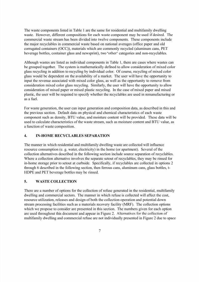
4. IN-HOME RECYCLABLES SEPARATION
The manner in which residential and multifamily dwelling waste are collected will influence
resource consumption (e. g. water, electricity) in the home (or apartment). Several of thecollection alternatives described in the following section include source separation of recyclables.
Where a collection alternative involves the separate setout of recyclables, they may be rinsed for
in-home storage prior to setout at curbside. Specifically, if recyclables are collected in options 2
through 6 described in the following section, then ferrous cans, aluminum cans, glass bottles, t-
HDPE and PET beverage bottles may be rinsed.
5. WASTE COLLECTION
There are a number of options for the collection of refuse generated in the residential, multifamily
dwelling and commercial sectors. The manner in which refuse is collected will affect the cost,
resource utilization, releases and design of both the collection operation and potential down
stream processing facilities such as a materials recovery facility (MRF). The collection options
which we propose to consider are presented in this section. The numbers given for each option
are used throughout this document and appear in Figure 2. Alternatives for the collection of
multifamily dwelling and commercial refuse are not individually presented in Figure 2 due to space

8/18/2019 121 Life Cycle Assessmnet of Solid Waste Management - Copy
http://slidepdf.com/reader/full/121-life-cycle-assessmnet-of-solid-waste-management-copy 15/35
8
limitations. The role of transfer stations is described in the following sections.
5.1 Collection of Residential Refuse and Recyclables
Mixed Refuse Collection
1. Collection of mixed refuse in a single compartment truck with no separation of
recyclables.
Recyclables Collection
2. Set out of commingled recyclables which are sorted by the collection vehicle crew at
the point of collection into a multi-compartment vehicle.
3. Collection of recyclables presorted by the generator into a multi-compartment
vehicle.
4. Collection of commingled recyclables in a vehicle with two compartments; one for all
paper components, and the other for non-paper recyclables.
Co-Collection
5. Collection of mixed refuse and recyclables in different colored bags for transport in a
single compartment of a vehicle. Bags would then be sorted at a MRF. All paper
recyclables are collected in one bag, and non-paper recyclables are collected in a
separate bag.
6. Collection of mixed refuse and recyclables in different colored bags in separate
compartments of the same vehicle. The refuse and recyclables would then be
delivered to a MRF and the mixed refuse would be delivered to a combustion facility,
composting facility, RDF plant or landfill. Commingled recyclables and mixed waste
are collected in a three compartment truck - one compartment for mixed waste, one
for paper recyclables, and the third compartment for non-paper recyclables.
Residuals Collection
7. If recyclables are collected in options 2, 3 or 4, then residual MSW is collected in a
single compartment vehicle as in option 1.
Recyclables Drop-Off
8/18/2019 121 Life Cycle Assessmnet of Solid Waste Management - Copy
http://slidepdf.com/reader/full/121-life-cycle-assessmnet-of-solid-waste-management-copy 16/35
9
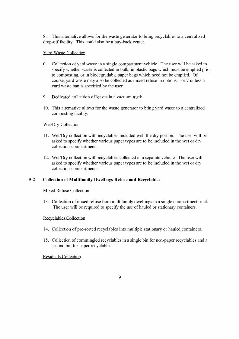
8. This alternative allows for the waste generator to bring recyclables to a centralized
drop-off facility. This could also be a buy-back center.
Yard Waste Collection
0. Collection of yard waste in a single compartment vehicle. The user will be asked to
specify whether waste is collected in bulk, in plastic bags which must be emptied prior
to composting, or in biodegradable paper bags which need not be emptied. Of
course, yard waste may also be collected as mixed refuse in options 1 or 7 unless a
yard waste ban is specified by the user.
9. Dedicated collection of leaves in a vacuum truck.
10. This alternative allows for the waste generator to bring yard waste to a centralized
composting facility.
Wet/Dry Collection
11. Wet/Dry collection with recyclables included with the dry portion. The user will be
asked to specify whether various paper types are to be included in the wet or dry
collection compartments.
12. Wet/Dry collection with recyclables collected in a separate vehicle. The user will
asked to specify whether various paper types are to be included in the wet or dry
collection compartments.
5.2 Collection of Multifamily Dwellings Refuse and Recyclables
Mixed Refuse Collection
13. Collection of mixed refuse from multifamily dwellings in a single compartment truck.
The user will be required to specify the use of hauled or stationary containers.
Recyclables Collection
14. Collection of pre-sorted recyclables into multiple stationary or hauled containers.
15. Collection of commingled recyclables in a single bin for non-paper recyclables and a
second bin for paper recyclables.
Residuals Collection
8/18/2019 121 Life Cycle Assessmnet of Solid Waste Management - Copy
http://slidepdf.com/reader/full/121-life-cycle-assessmnet-of-solid-waste-management-copy 17/35
10
16. If recyclables are collected in options 12 or 13, then residual MSW is collected in a
single compartment vehicle as in option 11.
Wet/Dry Collection
17. Wet/Dry collection with recyclables included with the dry portion. The user will be
asked to specify whether various paper types are to be included in the wet or dry
collection compartments.
18. Wet/Dry collection with recyclables collected in a separate vehicle. The user will
asked to specify whether various paper types are to be included in the wet or dry
collection compartments.
5.3 Collection of Commercial Waste
Recyclables Collection
19. Collection of presorted recyclables.
Mixed Refuse Collection
20. Collection of mixed refuse before or after recycling.
Multifamily dwelling waste may or may not be collected by the city in a manner similar to
residential refuse collection. Whether this waste is collected by the city or a private contractor
should not affect the LCI. The user will be asked to specify whether multifamily dwelling waste is
collected by the city. If yes, then this waste will be analyzed as part of the collection unitoperation. If no, then this waste will be collected by a private contractor and the user will be
asked to specify which, if any, components of MSW are recycled. Whether multifamily dwelling
waste is collected by the city or the private sector, its life-cycle implications and costs will be
included in the system.
6. TRANSFER STATIONS
Once refuse has been collected, there are a number of facilities to which it may be transported
including a transfer station, MRF, a combustion facility, RDF plant, composting facility or a
landfill. Prior to describing the manner in which each of these processes is handled, the potential
role of transfer stations is described.
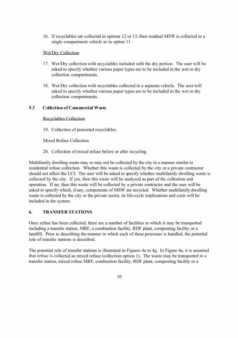
The potential role of transfer stations is illustrated in Figures 4a to 4g. In Figure 4a, it is assumed
that refuse is collected as mixed refuse (collection option 1). The waste may be transported to a
transfer station, mixed refuse MRF, combustion facility, RDF plant, composting facility or a

8/18/2019 121 Life Cycle Assessmnet of Solid Waste Management - Copy
http://slidepdf.com/reader/full/121-life-cycle-assessmnet-of-solid-waste-management-copy 18/35
11
landfill. If the waste is brought to a transfer station, then the waste could subsequently be brought
to any of these facilities. Waste flow down stream of a MRF, combustion facility, RDF plant or
composting facility plant is not illustrated in Figure 4 for simplicity. These flows are part of the
system and are illustrated in Figure 2. A transfer station handling mixed refuse will be referred to
as Transfer Station 1. Different transfer station designs will be required dependent upon the typeof waste processed.
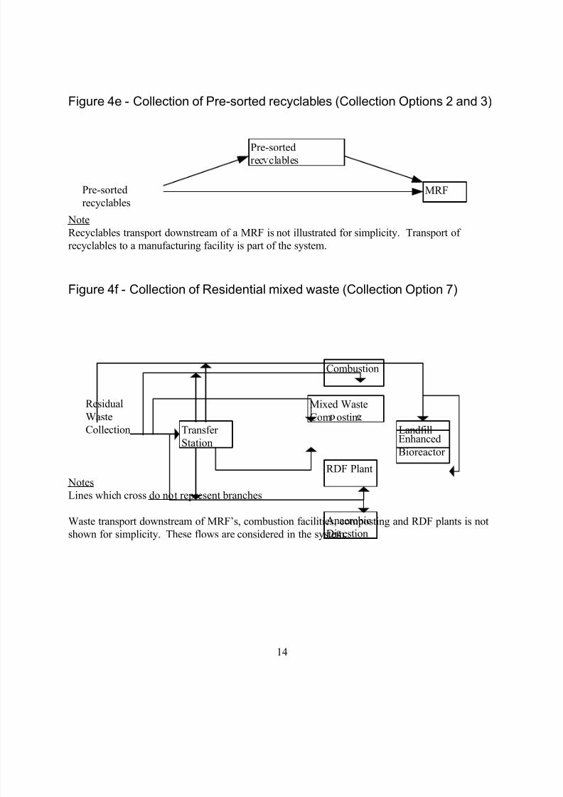
Figure 4b illustrates collection of presorted recyclables in collection options 2 and 3. In these
cases, recyclables could be transported either directly to a MRF designed to process presorted
recyclables or to a transfer station followed by a MRF.
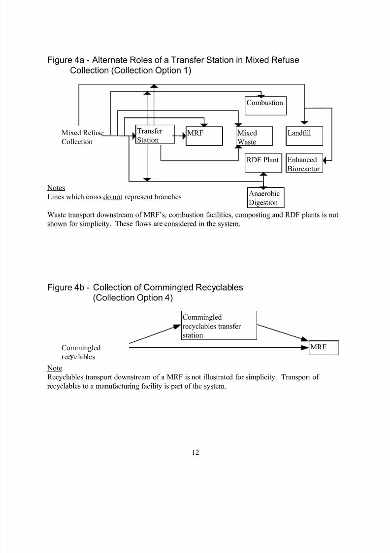
Figure 4c illustrates the collection of commingled recyclables. These recyclables may be
transported to either a transfer station (Transfer Station 3) or directly to a MRF designed to
process commingled recyclables (MRF 3).
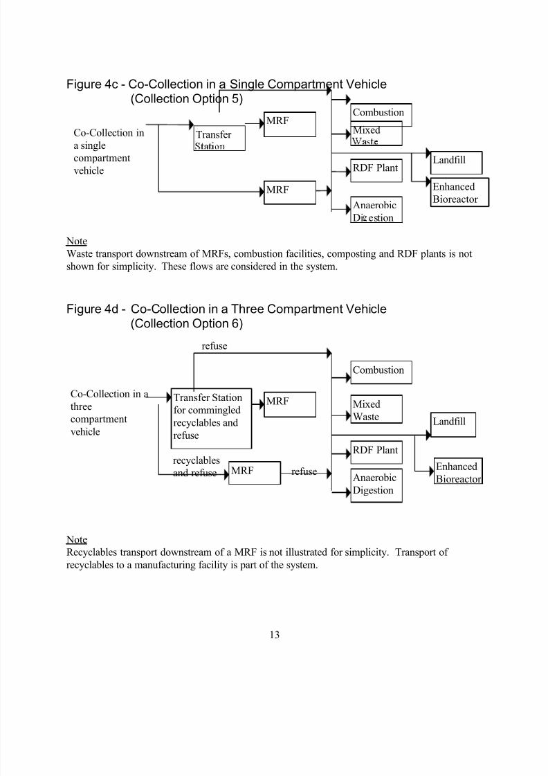
Figure 4d illustrates the role of a transfer station where refuse and recyclables areco-collected in a single compartment vehicle (collection option 5). In this case, refuse and
recyclables could be delivered to either a MRF or to a transfer station. If the refuse and
recyclables are delivered to a MRF, then the MRF also functions as a transfer station because the
refuse must be removed from the facility to either a combustion facility, RDF plant, composting
facility or a landfill. Alternately, the refuse could be delivered to a transfer station for separation
of the refuse and commingled recyclables.
Figure 4e illustrates the role of a transfer station in which refuse and recyclables are
co-collected in a three compartment vehicle (collection option 6). Commingled recyclables and
refuse may be transported to a transfer station where the recyclables and refuse are separated and
transported to regional waste management facilities. In this case, the refuse would then betransported to a combustion facility, composting facility, RDF plant or landfill and the recyclables
would be transported to a MRF designed to process commingled recyclables (MRF-3). This
transfer station is identified as Transfer Station 4. Alternately, the commingled recyclables and
refuse may be transported to MRF-5 where the recyclables are processed and the refuse is
transported to a combustion facility, RDF plant, composting facility or landfill.
The alternative roles of transfer stations in the collection of residual MSW assuming separate
collection of recyclables (collection option 7) are illustrated in Figure 4f. In this collection option,
recycling has already occurred. Thus, the MSW is transported to a combustion facility, RDF
plant, composting facility or landfill either through or around a transfer station.
8/18/2019 121 Life Cycle Assessmnet of Solid Waste Management - Copy
http://slidepdf.com/reader/full/121-life-cycle-assessmnet-of-solid-waste-management-copy 19/35
12
Figure 4a - Alternate Roles of a Transfer Station in Mixed RefuseCollection (Collection Option 1)
Notes
Lines which cross do not represent branches
Waste transport downstream of MRF’s, combustion facilities, composting and RDF plants is not
shown for simplicity. These flows are considered in the system.
Figure 4b - Collection of Commingled Recyclables(Collection Option 4)
Note
Recyclables transport downstream of a MRF is not illustrated for simplicity. Transport of
recyclables to a manufacturing facility is part of the system.
Transfer
StationMixed
Waste
Landfill
RDF Plant
MRF
Combustion
Mixed Refuse
Collection
Commingled
recyclables transfer
station
MRFCommingled
rec clables
AnaerobicDigestion
Enhanced
Bioreactor
8/18/2019 121 Life Cycle Assessmnet of Solid Waste Management - Copy
http://slidepdf.com/reader/full/121-life-cycle-assessmnet-of-solid-waste-management-copy 20/35
13
Figure 4c - Co-Collection in a Single Compartment Vehicle(Collection Option 5)
Note
Waste transport downstream of MRFs, combustion facilities, composting and RDF plants is not
shown for simplicity. These flows are considered in the system.
Figure 4d - Co-Collection in a Three Compartment Vehicle(Collection Option 6)
NoteRecyclables transport downstream of a MRF is not illustrated for simplicity. Transport of
recyclables to a manufacturing facility is part of the system.
Transfer
Transfer Station
for commingledrecyclables and
refuse
Mixed
MixedWaste
RDF Plant
RDF Plant
MRF
MRF
Combustion
Combustion
Co-Collection in a
threecompartment
vehicle
MRF
Landfill
Co-Collection ina single
compartment
vehicle
MRF
refuse
Landfill
refuse
recyclables
and refuse
Anaerobic
Di estion
Enhanced
Bioreactor
Anaerobic
Digestion
Enhanced
Bioreactor
8/18/2019 121 Life Cycle Assessmnet of Solid Waste Management - Copy
http://slidepdf.com/reader/full/121-life-cycle-assessmnet-of-solid-waste-management-copy 21/35
14
Figure 4e - Collection of Pre-sorted recyclables (Collection Options 2 and 3)
Note
Recyclables transport downstream of a MRF is not illustrated for simplicity. Transport of
recyclables to a manufacturing facility is part of the system.
Figure 4f - Collection of Residential mixed waste (Collection Option 7)
Notes
Lines which cross do not represent branches
Waste transport downstream of MRF’s, combustion facilities, composting and RDF plants is not
shown for simplicity. These flows are considered in the system.
Pre-sorted
rec clables
MRFPre-sorted
recyclables
Transfer
Station
Mixed Waste
Com ostinLandfill
RDF Plant
Combustion
Residual
WasteCollection
Anaerobic
Di estion
Enhanced
Bioreactor
8/18/2019 121 Life Cycle Assessmnet of Solid Waste Management - Copy
http://slidepdf.com/reader/full/121-life-cycle-assessmnet-of-solid-waste-management-copy 22/35
15
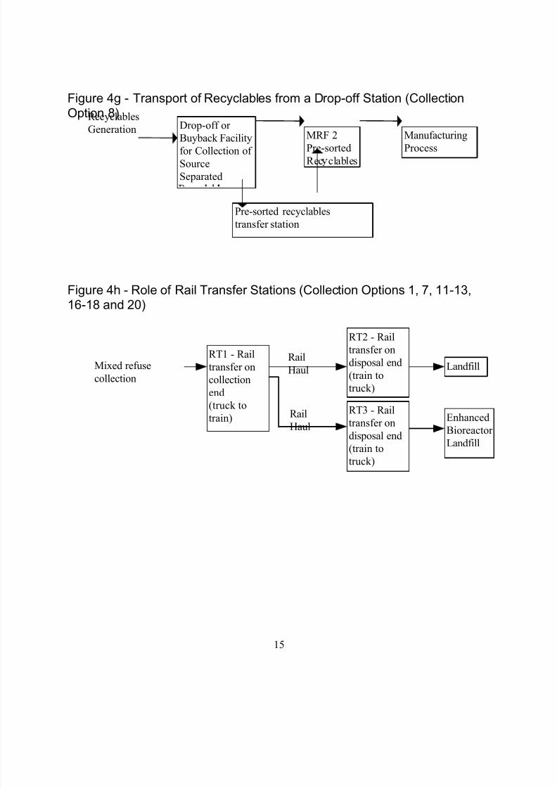
Figure 4g - Transport of Recyclables from a Drop-off Station (CollectionOption 8)
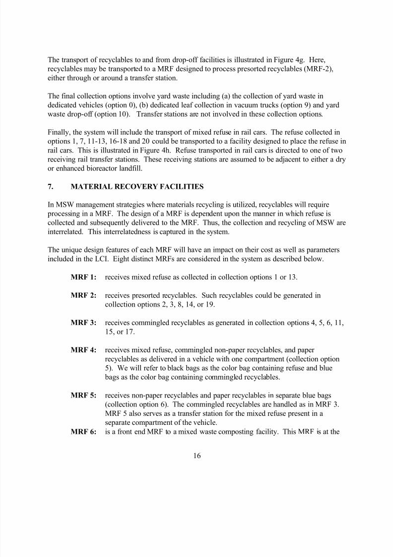
Figure 4h - Role of Rail Transfer Stations (Collection Options 1, 7, 11-13,16-18 and 20)
Drop-off or
Buyback Facilityfor Collection of
Source
Separated
ManufacturingProcess
Pre-sorted recyclables
transfer station
MRF 2Pre-sorted
Rec clables
Recyclables
Generation
RT1 - Rail
transfer on
collection
end
(truck to
train)
LandfillMixed refuse
collection
RT2 - Rail
transfer on
disposal end
(train to
truck)
Rail
Haul
EnhancedBioreactor
Landfill
RT3 - Railtransfer on
disposal end
(train to
truck)
RailHaul
8/18/2019 121 Life Cycle Assessmnet of Solid Waste Management - Copy
http://slidepdf.com/reader/full/121-life-cycle-assessmnet-of-solid-waste-management-copy 23/35
16
The transport of recyclables to and from drop-off facilities is illustrated in Figure 4g. Here,
recyclables may be transported to a MRF designed to process presorted recyclables (MRF-2),
either through or around a transfer station.
The final collection options involve yard waste including (a) the collection of yard waste indedicated vehicles (option 0), (b) dedicated leaf collection in vacuum trucks (option 9) and yard
waste drop-off (option 10). Transfer stations are not involved in these collection options.
Finally, the system will include the transport of mixed refuse in rail cars. The refuse collected in
options 1, 7, 11-13, 16-18 and 20 could be transported to a facility designed to place the refuse in
rail cars. This is illustrated in Figure 4h. Refuse transported in rail cars is directed to one of two
receiving rail transfer stations. These receiving stations are assumed to be adjacent to either a dry
or enhanced bioreactor landfill.
7. MATERIAL RECOVERY FACILITIES
In MSW management strategies where materials recycling is utilized, recyclables will require
processing in a MRF. The design of a MRF is dependent upon the manner in which refuse is
collected and subsequently delivered to the MRF. Thus, the collection and recycling of MSW are
interrelated. This interrelatedness is captured in the system.
The unique design features of each MRF will have an impact on their cost as well as parameters
included in the LCI. Eight distinct MRFs are considered in the system as described below.
MRF 1: receives mixed refuse as collected in collection options 1 or 13.
MRF 2: receives presorted recyclables. Such recyclables could be generated incollection options 2, 3, 8, 14, or 19.
MRF 3: receives commingled recyclables as generated in collection options 4, 5, 6, 11,
15, or 17.
MRF 4: receives mixed refuse, commingled non-paper recyclables, and paper
recyclables as delivered in a vehicle with one compartment (collection option
5). We will refer to black bags as the color bag containing refuse and blue
bags as the color bag containing commingled recyclables.
MRF 5: receives non-paper recyclables and paper recyclables in separate blue bags
(collection option 6). The commingled recyclables are handled as in MRF 3.
MRF 5 also serves as a transfer station for the mixed refuse present in a
separate compartment of the vehicle.
MRF 6: is a front end MRF to a mixed waste composting facility. This MRF is at the
8/18/2019 121 Life Cycle Assessmnet of Solid Waste Management - Copy
http://slidepdf.com/reader/full/121-life-cycle-assessmnet-of-solid-waste-management-copy 24/35
17
front-end of a mixed waste composting facility, i.e., the material recovery
operations precede composting operations. The MRF is similar to a mixed
waste MRF, but includes provisions for additional sorting to remove
contaminants from mixed waste that affect the composting product.
MRF 7: is a front end MRF to an anaerobic digestion facility: This MRF is at the front
end of an anaerobic digestion facility, i.e., material recovery operations precede
anaerobic digestion operations. The MRF is similar to a mixed waste MRF,
but includes additional sorting to remove contaminants that could adversely
affect the anaerobic digestion process, or the quality of the digested solids.
MRF 8: is a front-end MRF to a refuse derived fuel (RDF) facility. This MRF is at the
front end of an RDF facility, i.e., material recovery operations precede RDF
operations. The MRF is similar to a mixed waste MRF, but does not include a
magnet and eddy current separator for recovery of ferrous cans and aluminum.
These waste components are recovered in the RDF facility.

8/18/2019 121 Life Cycle Assessmnet of Solid Waste Management - Copy
http://slidepdf.com/reader/full/121-life-cycle-assessmnet-of-solid-waste-management-copy 25/35
18
TABLE 2. MATERIALS WHICH CAN BE RECYCLED AT EACH MRF TYPE
Recyclable
Component
MRF 1
Mixed
Refuse
MRF 2
Presorted
Recyclables
MRF 3
Commingled
Recyclables
MRF 4
Co-collection
Single Comp.
MRF 5
Co-collection
Double Comp.
Drop-Off
or Buyback
Center
Fe-cans x x x x x
x
Al-cans x x x x x x
clear glass x x x x x x
brown glass x x x x x x
green glass x x x x x x
mixed color
glass x x x x x
x
t-HDPE x x x x x x p-HDPE x x x x x x
PET-bvg. x x x x x x
plastic-other x x x x x x
mixed plasticsax x x x x x
ONP x x x x x x
O C C x x x
office paper x x x x x
paper-other x x x x x
mixed paper a x x x x x xaIncludes Anon-recyclable@ plastics or paper.
Based on previous work, we have concluded that the MRFs described above are most cost
effective when they include an automatic bag opener, a magnet for ferrous metal removal and an
eddy current separator for aluminum can removal. All other sorting is performed manually. We
propose to adopt these assumptions here, for purposes of developing MRF designs from which to
estimate cost and LCI parameters. However, the user will have the opportunity to specify
automated or manual equipment in certain cases.
The components of MSW which can be recovered in each of the different MRFs are listed in
Table 2. This table also lists the components which can be accepted at a drop-off facility
(collection option 8).
The technology associated with MSW sorting in MRFs is evolving. This can be accommodated
8/18/2019 121 Life Cycle Assessmnet of Solid Waste Management - Copy
http://slidepdf.com/reader/full/121-life-cycle-assessmnet-of-solid-waste-management-copy 26/35
19
by allowing the user to bypass the MRF design and input costs directly. Eight distinct MRFs are
required as described above. However, they have many overlapping design features which will
remain consistent between MRFs. The design for each MRF will be presented in detail as part of
the process model for MRFs.
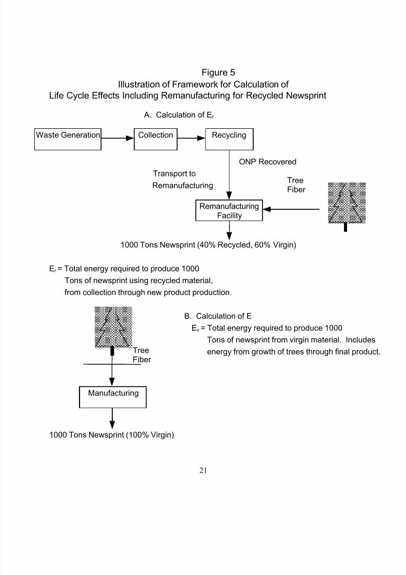
8. REMANUFACTURING AND ENERGY RECOVERY
As part of the LCI, we must account for all resources, energy, and environmental releases
associated with the recycling and reprocessing of a waste component. This section presents the
conceptual framework which we propose to use to account for resource expenditures and
potential savings due to the use of recycled materials. In management strategies where some
portion of the MSW is recycled, the recyclables will ultimately be delivered to a facility for
remanufacturing. Separation will occur during collection, at a MRF, or at another waste
management facility.
Energy and resources will be expended to deliver recyclables to a remanufacturing facility. At thefacility, additional energy and resources will be expended to convert the recyclables to a new
product. The total amount of energy required to recover the recyclable from the waste stream
and convert it to a new product will be included in the inventory analysis. This energy is termed
(Er ). In addition, the amount of energy required to produce a similar amount of product from
virgin material will be calculated. This energy is termed (Ev). The net amount of energy (En)
expended (or saved) to recycle a material will then be calculated as the difference between (E r )and
(Ev), where (En = Er - Ev).
While energy has been used here as an example, a similar calculation will be performed for all LCI
parameters involved in the remanufacturing process such as carbon dioxide and other air
emissions, wastewater pollutants, and solid waste, etc. This calculation assumes that a productmanufactured using recycled materials is indistinguishable from the same product manufactured
with virgin materials. Although not shown in Figure 5, ONP which is not recycled would be
disposed by combustion, conversion to RDF, composting, or a landfill as illustrated in Figure 2.
The calculation described above is illustrated conceptually for ONP in Figure 5. Figure 5 shows
the flow diagram which accounts for the total energy required to produce and deliver to
consumers 1000 tons of newsprint (as newspapers). As can be seen in Figure 5, newsprint is not
produced from 100% recycled material; some virgin material is mixed with the recycled fiber.
To develop the LCI, an assumption must be made with respect to which remanufacturing process
is utilized for a recyclable. In the case of ONP, the major use is the production of new newsprint.
However, some ONP is used in other applications (containerboard, cellulose insulation, animal
bedding, etc.). For each recyclable, it will be necessary to collect data on remanufacturing
processes to complete the LCI. Data collection efforts will focus initially on the major
remanufacturing process for each recyclable. Additional remanufacturing processes will be

8/18/2019 121 Life Cycle Assessmnet of Solid Waste Management - Copy
http://slidepdf.com/reader/full/121-life-cycle-assessmnet-of-solid-waste-management-copy 27/35
20
included to the extent that resources are available to collect data on more than one
remanufacturing process. The system is designed with the capacity to incorporate more that one
remanufacturing process into the analysis.
8/18/2019 121 Life Cycle Assessmnet of Solid Waste Management - Copy
http://slidepdf.com/reader/full/121-life-cycle-assessmnet-of-solid-waste-management-copy 28/35
21
TreeFiber
TreeFiber
Figure 5
Illustration of Framework for Calculation of
Life Cycle Effects Including Remanufacturing for Recycled Newsprint
A. Calculation of Er
ONP Recovered
Transport to
Remanufacturing
1000 Tons Newsprint (40% Recycled, 60% Virgin)
Er = Total energy required to produce 1000
Tons of newsprint using recycled material,
from collection through new product production.
B. Calculation of E
Ev = Total energy required to produce 1000
Tons of newsprint from virgin material. Includes
energy from growth of trees through final product
1000 Tons Newsprint (100% Virgin)
RemanufacturingFacility
Waste Generation Collection Recycling
Manufacturing
8/18/2019 121 Life Cycle Assessmnet of Solid Waste Management - Copy
http://slidepdf.com/reader/full/121-life-cycle-assessmnet-of-solid-waste-management-copy 29/35
22
In addition to recycled materials, an offset will also be required in management strategies where
energy is recovered from either the direct combustion of MSW, RDF, or landfill gas. The
conceptual framework described above may be applied here as well. Energy recovered from the
MSW will be credited to that management strategy. In calculating emissions reductions
associated with energy recovery, we assume that anyAsaved
@ electrical energy resulted from fossil
fuel (coal, oil, or natural gas) and not from hydro or nuclear power.
9. COMPOSTING
Composting is the aerobic biodegradation of organic matter and is considered as a treatment
alternative. We propose to consider composting of yard waste and mixed waste. Yard waste
composting may occur in either a centralized municipal facility or in a generator's
backyard. Here, we consider a centralized composting facility. Backyard composting will be
considered in Section 14 on source reduction.
We propose to consider two alternatives for yard waste composting; a low and mediumtechnology facility. The major difference between these two facilities is the degradation rate of
the yard waste as influenced by the turning frequency. The detention times are assumed to be 540
and 270 days for the low and medium technology facilities, respectively. Turning is accomplished
with either a front end loader once per year (low) or a windrow turner 25 times per year
(medium). Other major differences between the low and medium technology facilities include
water addition, post process screening and the potential to treat leachate. The type of facility to
be considered will be a user input parameter. Neither facility includes an automated air supply
system. Branches will be shredded prior to composting in both the low and medium technology
facilities.
Yard waste may be delivered in collection vehicles or dropped off by the waste generator. Inaddition, leaves may be delivered in vacuum trucks. If yard waste is delivered in bags, then the
user will be asked to specify whether the bags are biodegradable, in which case they will not
require emptying, or non-biodegradable, in which case they will need to be emptied and the bags
will represent a residual. Yard waste may also be delivered in bulk.
The design of the mixed waste composting facility will be based on mechanical aeration. The
facility will include preprocessing of the incoming waste stream to remove any non-compostable
recyclables such as glass, metal, and plastic as well as any non-compostable non-recyclables. The
waste flow equations are written so that paper may or may not be removed in the preprocessing
step.
8/18/2019 121 Life Cycle Assessmnet of Solid Waste Management - Copy
http://slidepdf.com/reader/full/121-life-cycle-assessmnet-of-solid-waste-management-copy 30/35
23
10. WASTE-TO-ENERGY COMBUSTION
Combustion represents a treatment alternative in which the volume of MSW requiring burial is
significantly reduced. We consider a waste-to-energy (WTE) combustion facility in which MSWis burned with subsequent energy recovery in the form of electricity. Facilities in which energy is
not recovered as well as facilities in which energy is recovered as steam are excluded from the
system. The rationale for this selection is that the majority of combustion facilities constructed
today include energy recovery as electricity.
The cost, energy production, and emission factors for the WTE combustion facility will be
developed on the basis of BTU of input waste per day, as opposed to tons per day which is more
standard. In so doing, we are able to link the cost and energy yield of combustion to waste
composition. The BTU value of the waste input to a combustion facility will be calculated from
default data on the BTU value of individual waste components and the composition of waste
entering the facility. Thus, if the BTU value of MSW changes, the effect will be incorporated intoestimates of potential energy recovery. This will allow comparison of the relative net benefits of
recycling and combustion with energy recovery in the optimization module.
For a combustion facility to be feasible, a critical mass of refuse is required. The critical mass will
be set up as an input parameter so that (1) a solid waste management alternative with an
unacceptably small combustion facility is not proposed and (2) future changes in technology
resulting in a change in the critical mass can be incorporated in the system. The combustion
facility will include appropriate air pollution control equipment to meet current regulations.
11. REFUSE DERIVED FUEL (RDF) AND CO-COMBUSTION
In addition to combustion as discussed in the previous section, two alternatives for recovery of
the energy value of MSW will be considered in the solid waste management system, RDF and co-
combustion. In the system described here, RDF production refers to the separation of MSW into
a product stream with a relatively high BTU value and a residual stream with a relatively low
BTU value. Of course, the efficiency of the separation of MSW into these streams will be less
than 100%. There are many variations on the RDF theme including the production of shredded
refuse for direct combustion, and the production of pellets for shipment over longer distances.
The most common RDF processes will be identified in future work so that one or more generic
RDF plant designs can be developed. These designs will be used as the basis for which cost,
energy, and emission factors are developed.
The division between an RDF plant and a MRF is not entirely distinct as metals separation
typically occurs in an RDF plant. Thus, if RDF is part of an MSW management strategy, then it
would probably not be necessary to remove tin cans separately. Similarly, an eddy current
separator at an RDF plant would eliminate its need at a MRF. As more information is developed

8/18/2019 121 Life Cycle Assessmnet of Solid Waste Management - Copy
http://slidepdf.com/reader/full/121-life-cycle-assessmnet-of-solid-waste-management-copy 31/35
24
on RDF plants, we will propose the manner in which the interrelationship between an RDF plant
and a MRF will be handled.
Another manner in which energy can be recovered from MSW is by the combustion of particular
components of the stream in industrial boilers. This could include utility boilers, hog fuel boilersin the paper industry and the like. The system allows for the recovery of a mixed waste paper
stream and a mixed waste plastics stream during recycling. One or both of these streams could be
used as fuel for an industrial boiler.
12. ANAEROBIC DIGESTION
Anaerobic digestion of MSW could occur in either a reactor or by operation of a landfill with
leachate recycling for enhanced refuse decomposition and methane production. Here we refer to
digestion in a reactor. The facility will include preprocessing of the incoming waste stream to
remove any non-degradable recyclables such as glass, metal, and plastic as well as any non-
degradable non-recyclables. The waste flow equations are written so that paper may or may not be removed in the preprocessing step.
13. LANDFILLS
Three types of landfills will be considered in the system; one designed for the receipt of mixed
refuse and a second designed for the receipt of ash only. The mixed refuse landfill will be
designed according to RCRA Subtitle D and Clean Air Act standards. However, the user will
have the opportunity to specify either a more lenient or stricter design with respect to the liner
and cover systems. The landfill will be operated as a dry landfill. Consideration of the operation
of a landfill with leachate recycle for enhanced decomposition and methane production was
discussed in the previous section. The system will include both gaseous and liquid releases fromthe landfill. The user will be required to specify whether gas is flared, recovered for energy,
vented to the atmosphere or allowed to diffuse out of the landfill. This information, coupled with
data on landfill gas production, will be used to estimate atmospheric emissions. Estimates will
also be developed for the amount of leachate requiring treatment. This leachate will be treated in
an offsite treatment facility. Energy and emissions associated with leachate treatment will be
considered in the LCI.
Municipal waste combustion ash will be directed to a second landfill designed to accept ash. Even
when a community utilizes combustion, there will be some material which should not be routed to
a combustion facility and also times when it is out of service. Thus, we expect that the design for
an ash landfill will include a relatively small section designed for the receipt of mixed refuse.
A third landfill will be designed with leachate recycling to enhance refuse decomposition, methane
production, and leachate treatment. As above, the system will include both gaseous and liquid
emissions. The user will be required to specify whether gas is flared or recovered for energy.
8/18/2019 121 Life Cycle Assessmnet of Solid Waste Management - Copy
http://slidepdf.com/reader/full/121-life-cycle-assessmnet-of-solid-waste-management-copy 32/35
25
This information, coupled with data on landfill gas production, will be used to estimate
atmospheric emissions.
14. SOURCE REDUCTION
As illustrated in Figure 1, source reduction represents the difference between potential and actual
waste generation. Source reduction represents a reduction in mass or toxicity. Source reduction
may lead to reductions in other LCI parameters such as COD production or particulate emissions.
The effects of source reduction are unique to very specific components of the waste stream. The
conceptual framework for modeling source reduction is described first, followed by examples of
how it could be applied.
With reference to Figure 1, the box entitled source reduction represents a series of multipliers that
adjust the waste generation rate resulting from a source reduction program. These numbers are
multiplied by the waste quantities in the potential waste generation box to calculate actual waste
generation. Source reduction will include a series of multipliers, with unique values for changes inwaste mass and each LCI parameter. These multipliers will be set up as individual input
parameters in a preprocessor so that where the user has data on a specific process, it can be used.
Collection of data on specific industrial processes for evaluation of source reduction is beyond
the scope of this project.
Source reduction is generally applied to very specific components of the waste stream. Examples
might include a lighter napkin with equivalent absorbency, or a napkin produced by an alternative
manufacturing process which reduces waste production. Napkins are not one of the waste
components listed in Table 1. Rather than divide the waste stream into the individual components
which make up MSW in order to specifically include napkins, we propose to provide additional
Adummy waste components@ in the waste composition data input section. These dummy variablescould be used in the same way as the A paper-other @ category. That is, if a user wishes to focus on
napkins, then the user would consider one of the dummy variables to be napkins and then enter
the appropriate multipliers to account for mass and other LCI parameter reductions (or increases)
associated with the production of a different napkin. If a waste were to be converted from a non-
recyclable to a recyclable form, then its composition would have to be considered as part of one
of the recyclable components identified in Table 2. If this is inappropriate, then the waste
generation model will require modification.
A simpler example of the source reduction is backyard composting. Here, yard waste which is
composted by the waste generator does not enter the MSW collection system. A multiplier would
be used to reflect the decreased mass of yard waste in MSW. Yard waste not collected would not
require energy for collection or further processing in a centralized composting facility. However,
there are life-cycle effects associated with backyard composting and these are accounted for in a
dedicated process model. The backyard composting process model will account for emissions
associated with biodegradation as well as emissions associated with the use of a chipper for size
8/18/2019 121 Life Cycle Assessmnet of Solid Waste Management - Copy
http://slidepdf.com/reader/full/121-life-cycle-assessmnet-of-solid-waste-management-copy 33/35
26
reduction of branches. In the process model, the user will have to specify the fraction of backyard
compost where a chipper is utilized.
15. SUMMARY OF SYSTEM BOUNDARIES
The system has largely been defined through the description of the functional elements and unit
operations, as presented in this document, and the manner in which each will be treated. This
section provides a summary of the system boundaries and explains how and why the boundaries
for the environmental(LCI) analysis are different from the boundaries used for cost analysis.
15.1 System Boundaries for LCI
In general, we will evaluate all data which have a bearing on the LCI from materials acquisition
through waste disposal or remanufacturing. Where a material is recycled and a new product is
produced, the resources, energy, and environmental releases associated with production of the
new product, as well as those saved by using a recycled material instead of a virgin material, will be considered. This concept also applies to energy recovery from combustion as described in
more detail in Section H and in Figure 5.
In considering remanufacturing, we will evaluate LCI parameters from the recovery of a raw
material through its conversion to a product. Where petroleum is a raw material, the analysis
would include all activity beginning with recovery of petroleum from the earth. Where energy is
required in a process, the energy associated with production of the energy (precombustion
energy) and the wastes associated with energy production will be considered. Where trees are
utilized, resources associated with growing and harvesting the tree will be considered.
The functional elements of MSW management include numerous pieces of capital equipment fromrefuse collection vehicles to balers to major equipment at paper mills. Resources are associated
with the fabrication of capital equipment as well as the construction of a new facility. In theory,
these resources should be considered in the LCI. This may be particularly relevant in evaluation
of waste management strategies which suggest the construction of a new facility, such as a MRF,
or the purchase of new refuse collection vehicles. While inclusion of capital equipment appears to
be theoretically correct, it introduces additional complexity which may not be necessary.
Sensitivity analysis will be used as a screen to evaluate the importance of its inclusion in the LCI.
It is difficult to identify cases where capital equipment and facility construction can or cannot be
neglected ahead of time and issues such as this will be brought out for discussion as they arise.
A second type of resource that may be neglected is the energy associated with the operation of a
facility's infrastructure, or Aoverhead@ energy. For example, energy will be expended for the
operation of refuse collection vehicles. We expect that a much smaller amount of energy will be
expended for operation of the office through which the vehicle routes are developed and the
collection workers are supervised. Our hope is to obtain estimates of this Aoverhead@ energy

8/18/2019 121 Life Cycle Assessmnet of Solid Waste Management - Copy
http://slidepdf.com/reader/full/121-life-cycle-assessmnet-of-solid-waste-management-copy 34/35
27
based on utility bills. If this energy is less than 5% of the energy utilized by the collection
vehicles, then it will be neglected unless standard overhead energy consumption factors are
available. This will save the project the resources required to estimate such energy more precisely
and will not affect the quality of the project output.
Another system boundary is that at the waste treatment and disposal end of the system. Where
wastes are generated which require treatment, the energy associated with their treatment will be
considered. If a solid waste is produced which requires burial, energy will be consumed in the
transport of that waste to a landfill and its burial in the landfill.
15.2 System Boundaries for Cost Analysis
In this section, we propose that the system boundary for cost analysis differ from that of the LCI.
We propose that our cost analysis focus on the cost of waste management as experienced by the
public sector. Thus, the cost analysis will include the cost of waste collection, transfer stations,
MRFs, composting facilities, combustion, RDF plants, and landfills. In addition, where a waste is produced as part of a waste management facility, the cost of waste treatment will be included in
the cost analysis of that facility. For example, we will include the cost of leachate treatment in our
cost analysis of landfills. The cost analysis boundary will also include the cost of educational or
other materials associated with source reduction or other aspects of solid waste management.
The boundary for the cost analysis will be drawn at the points where waste is buried and
recyclables are shipped to a downstream processor. For example, if recyclables were shipped
from a MRF, the cost analysis would end where the public sector received revenue (or incurred a
cost) in exchange for recyclables. The same analysis would apply to the sale of RDF or
electricity. The user must be cautioned that there are situations where the revenue realized from
the sale of a recyclable is artificially high. This has occurred in the past where a manufacturer hastaken steps to encourage the recycling of a material by offering an artificially high price. Such
situations may arise when recycling of a waste component not typically recycled begins. This
situation would not be expected to persist for a period of several years.
One cost to be excluded from the cost analysis is the cost of remanufacturing. However, we feel
that this cost is reflected in the price paid to a community for recyclables or electricity.
The user will have the option to enter costs directly if known, or provide sufficient design
information to estimate costs. Where costs are estimated, we propose to estimate costs in the
absence of an allowance for profit. The user could then be given the opportunity to specify a
profit margin if the user expects that a waste management unit operation will not be operated in
the public sector. The calculated cost will then be adjusted upwards prior to its use.
In summary, by focusing on costs incurred in the public sector, the analysis will be of most use to
local officials responsible for development of strategies for solid waste management.

8/18/2019 121 Life Cycle Assessmnet of Solid Waste Management - Copy
http://slidepdf.com/reader/full/121-life-cycle-assessmnet-of-solid-waste-management-copy 35/35
28
REFERENCES
U.S. Environmental Protection Agency. 1994. Characterization of Municipal Solid Waste in the
United States: 1992 Update. EPA/530-R-94-042. Office of Solid Waste, Washington, DC.