Embed Size (px)
Citation preview

12/08/2015
1
DNV GL © 2013 August 2015 SAFER, SMARTER, GREENER DNV GL © 2013
August 2015
OIL & GAS
Introduction to Subsea Production Systems
1
05 Templates and Manifolds
DNV GL © 2013 August 2015
Template and manifold
2

12/08/2015
2
DNV GL © 2013 August 2015
Goal
Know the purpose and design requirements for templates
Know the purpose and basic functions of a manifold
3
DNV GL © 2013 August 2015
Codes and standards
The following standards are a selection normally used for template/manifold design. The code requirements will vary with customer preference and local legislation
– ISO 13628-15 Subsea structures and manifolds (2011)
– ISO 13628-1 General requirements and recommendations
– Steel structure: Eurocode 3
– NORSOK U-001 (Dropped objects)
– ASME B 31.3 (Process piping)
– ASME B 31.8 (Gas transmission piping)
– DNV-OS-F101 (Submarine pipeline systems)
– BS8010 Part 3
– DNV standards for planning and Execution of Marine Operation
4

12/08/2015
3
DNV GL © 2013 August 2015
Templates
Guide, hang off and
support to drilling
and to the wellhead
conductor
Base for the subsea
trees and the
manifold
5
DNV GL © 2013 August 2015
Template Design
The design of the template will vary
with:
Location
– Local legislation
Installation methods
– Moonpool, drillpipe, crane vessel,
modular, barge or wet tow
Pipeline methods
– Horizontal or vertical flowline
connection, pipeline forces,
Protection requirements
– Fishing gear protection, dropped
objects
Drilling methods
– Suction of drill cuttings, cement
suction, drill cutting injection
6
12/08/2015
4
DNV GL © 2013 August 2015
Modular Manifold / Template
TRIPLE
PORCH
MUDMAT CENTRE
PILE
EWA
HOGS
DRILL CUT
INJECTION
PGB PGB
MANIFOLD PIG LOOP
MODULE
PIG LOOP
PORCH
CENTRE
SECTION
MANIFOLD ROOF
PROTECTION
7
DNV GL © 2013 August 2015
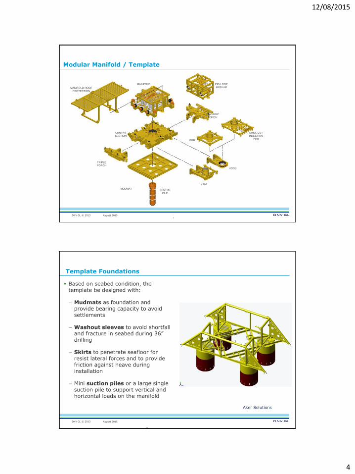
Template Foundations
Based on seabed condition, the template be designed with:
– Mudmats as foundation and provide bearing capacity to avoid settlements
– Washout sleeves to avoid shortfall and fracture in seabed during 36” drilling
– Skirts to penetrate seafloor for resist lateral forces and to provide friction against heave during installation
– Mini suction piles or a large single suction pile to support vertical and horizontal loads on the manifold
Aker Solutions
8

12/08/2015
5
DNV GL © 2013 August 2015
Mini Suction Piles
Template foundations with skirts or mini-suction piles :
Installed before main manifold so reduced weight
Allow drilling taking place (normally one season prior to manifold installation)
Each mini pile can be sucked down individually to adjust elevation
Supports weight of manifold or template and anchors it in place on the seabed
Aker Solutions
9
DNV GL © 2013 August 2015
Single Suction Piles
Key features :
Supports vertical and horizontal
loads on the template
Also used as anchor foundations
for FPSO or Semi-submersible
moorings
Installed partially by self weight
and then by ROV deployed pump
Can be recovered by reverse
pumping
May be designed so that
orientation is not critical during
installation
10

12/08/2015
6
DNV GL © 2013 August 2015
Fixed Template – Production Guidebase
Aker Solutions
11
DNV GL © 2013 August 2015
Hinged Manifold / Template
12

12/08/2015
7
DNV GL © 2013 August 2015
Manifolds
A manifold is a system of headers, branched piping and valves used to gather produced fluids or to distribute injected fluids.
The manifold should provide sufficient piping, valves and flow controls to safely gather produced fluids or distribute injected fluids such as gas, water or chemicals. (ISO 13628-1)
The Manifold Module provides the interface
between the production pipeline, flowline and well.
Pipelines or flexibles normally interconnect the manifold.
Collecting produced fluids from individual subsea wells.
Distributing production fluids, inject gas, inject chemicals and control fluids.
Distribute the electrical and hydraulic system.
Several XT can be connected to the manifold.
Satellite modules (if required) will be connected to the manifold via a flow line.
13
Aker Solutions (Kristin)
DNV GL © 2013 August 2015
Manifold headers
Flowlines / piping are connected to one or two headers in the manifold.
Two production headers have the advantage of:
Increased flexibility in export options
Increased flexibility for future tie-ins
Increased production availability
Possibility for installing a pigging loop
Possibility for hydrate plug removal from two sides
…at the cost of increased complexity and weight
15

12/08/2015
8
DNV GL © 2013 August 2015
Manifold Piping
6” Branch Line To/From
Well
Remote Actuated
Valves
10 ” Main Header
5 1/8” Branch
Valves
Pigging Loop Isolation Valve
2” CI
Valves
ROV
Panel
16
DNV GL © 2013 August 2015
Manifold
17

12/08/2015
9
DNV GL © 2013 August 2015
Manifold Piping
DNV GL © 2013 August 2015
Manifold deployment
19
12/08/2015
10
DNV GL © 2013 August 2015
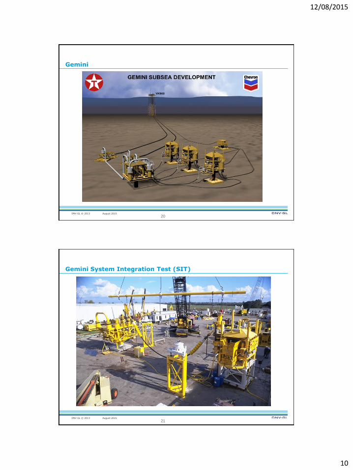
Gemini
20
DNV GL © 2013 August 2015
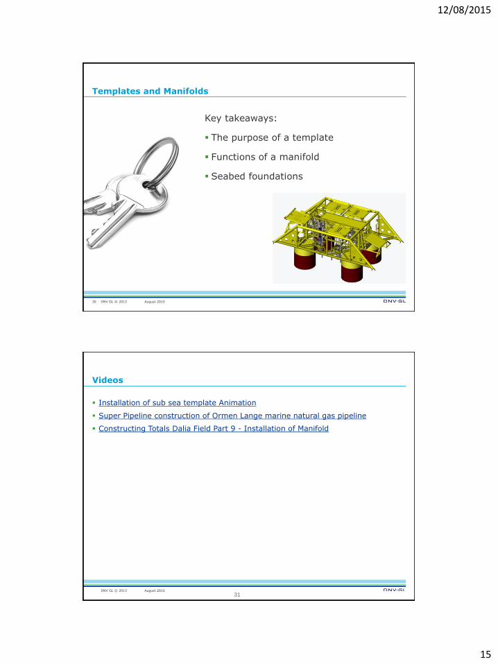
Gemini System Integration Test (SIT)
21

12/08/2015
11
DNV GL © 2013 August 2015
22
Manifold System Integration Testing (SIT)
DNV GL © 2013 August 2015
Manifold and distribution System
Manifold centers w/o template
function
23

12/08/2015
12
DNV GL © 2013 August 2015
Foundations
From ISO 13628-1
1. Riser joint
2. Applied moments
3. Environmental (current, wave
action, snag loads, etc.)
4. Flowline connection
5. Soil reaction
6. Thermal
24
DNV GL © 2013 August 2015
Foundations
The two main methods used are:
1. The 30” suspension joint are suspended by drilling rig during cementing.
Common for satellites.
2. The 30” suspension joint is hung off in a drilling guide base or in a template
structure.
Soil condition, external loading capacity to wellhead and the installed
infrastructure are selection criteria for the method. The load can be illustrated
with trawl protection, riser loads and drilling loads.
25

12/08/2015
13
DNV GL © 2013 August 2015
Foundations
Two main methods for foundation.
Example of method 1 Example of method 2
26
DNV GL © 2013 August 2015
Cluster Manifold
GE Oil & GAS: KIZOMBA manifold & foundation
27

12/08/2015
14
DNV GL © 2013 August 2015
Template Manifold
GE Oil & GAS: SKARV manifold & foundation
28
DNV GL © 2013 August 2015
Template Manifold
GE Oil & GAS: Snøhvit manifold & foundation
29
12/08/2015
15
DNV GL © 2013 August 2015
Templates and Manifolds
Key takeaways:
The purpose of a template
Functions of a manifold
Seabed foundations
30
DNV GL © 2013 August 2015
Videos
Installation of sub sea template Animation
Super Pipeline construction of Ormen Lange marine natural gas pipeline
Constructing Totals Dalia Field Part 9 - Installation of Manifold
31

12/08/2015
16
DNV GL © 2013 August 2015
SAFER, SMARTER, GREENER
www.dnvgl.com
32