Embed Size (px)
Citation preview

(12) United States Patent Temple et al.
US008505949B2
US 8,505,949 B2 Aug. 13, 2013
(10) Patent No.: (45) Date of Patent:
(54)
(75)
(73)
(*)
(21)
(22)
(65)
(60)
(51)
(52)
(58)
AUTOMATIC PNEUMATIC/ELECTRICAL COUPLERSYSTEM FOR TRACTOR-TRAILER COMBINATION VEHICLES
Inventors: Kevin Temple, Rochester, MI (US); Ryan Sullivan, Rochester, MI (US); Jason Hammel, Neenah, WI (US); Andrew Jaworski, Kansas City, MO (US); Kevin Bence, Grand Rapids, MI (US)
Assignee: SAF-Holland, Inc., Holland, MI (US)
Notice: Subject to any disclaimer, the term of this patent is extended or adjusted under 35 U.S.C. 154(b) by 539 days.
Appl. No.: 12/758,173
Filed: Apr. 12, 2010
Prior Publication Data
US 2011 FOO37241A1 Feb. 17, 2011
Related U.S. Application Data Provisional application No. 61/168.396, filed on Apr. 10, 2009.
Int. C. B60D L/64 (2006.01) B62D 53/12 (2006.01) U.S. C. CPC ................ B60D 1/64 (2013.01); B62D 53/125
(2013.01) USPC ............................ 280/.420: 280/421: 280/422 Field of Classification Search USPC .......................................... 280/.420, 421, 422 See application file for complete search history.
40AS 36A '120'N Aéas
(56) References Cited
U.S. PATENT DOCUMENTS
3,628,811 A * 12/1971 Rivers ........................... 280,421 3,711,122 A * 1/1973 Holmberg etal ... 280,421 3,888,513 A * 6/1975 Pilz et al. ...................... 280,421
(Continued) FOREIGN PATENT DOCUMENTS
4435630 A1 5, 1996 197O5275 A1 9, 1998
(Continued) OTHER PUBLICATIONS
BSI Group, "Standard in development: BS ISO 13044-1 Road Vehicles—Fully Automatic Coupling Systems 24 V (FACS) for heavy commercial vehicle combinations—Part 1: General Require ments and Definitions.” http://standardsdevelopment.bsigroup.com/ Home/Project/200903347. The British Standards Institution, Jan. 7. 2011.
DE DE
(Continued)
Primary Examiner — Paul N Dickson Assistant Examiner — Wesley Potter (74) Attorney, Agent, or Firm — Price Heneveld LLP
(57) ABSTRACT A powered coupling system is configured to interconnect utility lines such as fluid and/or electric lines of a vehicle tractor to a trailer. A curved track is mounted to a frame of the tractor, and the system includes pneumatic and/or electrical connectors that move along the curved track to align the connectors with a corresponding connectors on a trailer. A linear actuator causes the connectors on the tractor to shift Vertically to connect and disconnect the connectors on the tractor to connectors on the trailer. The curved track permits alignment of the connectors on the tractor with the connectors on the trailer even if the trailer is not in a straight line with the tractOr.
23 Claims, 6 Drawing Sheets
ce
96 y 36 38 859, 40
12 86
82
30

US 8,505,949 B2 Page 2
(56) References Cited EP 1652697 A1 2/2001 EP 1777084 A1 T 2005 EP 1918179 A1 10, 2006
U.S. PATENT DOCUMENTS EP 1998.965 B1 3, 2007
3,941,408 A * 3/1976 Petersson . 280,421 EP 1878629 A2 1/2008 4,943,079 A * 7/1990 Harbold ...... 280,420 WO 2004087475 A1 10, 2004 5,346,239 A * 9/1994 Wohlhuter . 280,420 WO 2004O98965 A1 11 2004 6,179,319 B1* 1/2001 Malisch et al. 280,477 WO 2007104544 A1 9, 2007 7,967,319 B2 * 6/2011 Alguera ........................ 280,420 OTHER PUBLICATIONS
2008/0100032 A1* 5/2008 Alguera Gallego et al. .. 280/420
DE DE DE DE DE DE DE
FOREIGN PATENT DOCUMENTS
29923081 U1 102O1559 A1 20305175 U1 20307381 U1
102004024333 A1 202005O18217 U1 102006.033899 A1
5, 2000 10, 2002 10, 2003 10, 2003 12/2005 5, 2006 1, 2008
BSI Group, "Standard in development: BS ISO 13044-1 Road Vehicles—Fully Automatic Coupling Systems 24 V (FACS) for heavy commercial vehicle combinations—Part 2: 50 mm fifth wheel couplings—electrical standardsdevelopment.bsigroup.com/Home/Project/200903348, The British Standards Institution, Jan. 7, 2011.
* cited by examiner
and pneumatic interface.” http://
U.S. Patent Aug. 13, 2013 Sheet 1 of 6 US 8,505,949 B2
32,36,38

US 8,505,949 B2 Sheet 2 of 6 Aug. 13, 2013 U.S. Patent

U.S. Patent
Fig. 2A
St.
Aug. 13, 2013
86
2
Sheet 3 of 6
SELE 56 Elsie. 116 115
78
30 68 7O 72
, II.
. 4 25-1 '' '' (AN
20
Y M SYNNNNS
US 8,505,949 B2
2. - - - w - - - - - - - - - - - - - - - - - - -m a a w !---
46
U.S. Patent Aug. 13, 2013 Sheet 4 of 6 US 8,505,949 B2

US 8,505,949 B2 Sheet 5 of 6 Aug. 13, 2013 U.S. Patent

U.S. Patent Aug. 13, 2013 Sheet 6 of 6 US 8,505,949 B2
101 1 O2 104
Pneumatic Cylinder Partially Extends
Cart MoVement
Starts
Trailer Plug Found, Cart
Stops Truck and Trailer
Couple System is Triggered
Plugs Lock Plug Detaches Plugs Together, Detach Trailer Lines from the
y Connected from Pneumatic are Charged Pneumatic Extension Cylinder Cylinder 105 106 107 108 109
Pneumatic SVStem GO Light is Cylinder y 9 Truck Ready for CartReturns to Activated in the Cab Home Position Retracts Transportation
110 111 112 113

US 8,505,949 B2 1.
AUTOMATIC PNEUMATIC/ELECTRICAL COUPLERSYSTEM FOR
TRACTOR-TRAILER COMBINATION VEHICLES
CROSS-REFERENCE TO RELATED APPLICATIONS
This application claims priority under 35 U.S.C. S 119(e) and the benefit of U.S. Provisional Application No. 61/168, 396 entitled AUTOMATIC PNEUMATIC/ELECTRICAL COUPLERSYSTEM FORTRACTOR-TRALLER COMBINATION VEHICLES, filed on Apr. 10, 2009, the entire disclosure of which is incorporated herein by reference.
BACKGROUND OF THE INVENTION
1. Field of the Invention The present invention relates to an automated and/or
remotely controlled system for the connection and disconnec tion of the pneumatic and electrical service connections between a tractor and trailer.
2. Technical Background Connecting the pneumatic systems (service and emer
gency air) and electrical systems between tractor and trailer has typically required a driver or other user to manually interconnect two connectors (electric and air) that are typi cally located on a pair of extensible cables located on the back of the tractor and a set of mating receptacles mounted on the front of the trailer. This process requires the driver to exit the cab upon Successfully coupling the tractor-trailer combina tion utilizing a fifth wheel device mounted on the tractor and a kingpin mounted on the trailer. The driver then typically climbs onto the rear frame of the tractor to access and manipu late the connection cables. This process is reversed upon tractor/trailer un-coupling.
Semi-automatic and fully automated pneumatic/electric coupling systems have been proposed, including concepts which utilize air and/or electrical connectors on/in the king pin. Another approach utilizes a fixed connector on the fifth wheel or tractor frame and a moveable receiver assembly on the trailer to provide for misalignment between the tractor and the trailer.
SUMMARY OF THE INVENTION
A coupler system according to one aspect of the present invention includes a multi-function connector with flexible, extensible lines or cables, integrated with a tractor-mounted mechanism which provides lateral and vertical movement. The system may include a plurality of sensors and control logic which enable the multi-function connector to locate, mate, and lock with a receptacle mounted on a trailer. Once connected and locked, the tractor-mounted mechanism dis engages and returns to a stowed or parked position, leaving the multifunction connector in place on the trailer. The cou pler system is able to reverse the process, i.e., re-engage the multi-function connector, unlock and disconnect from the trailer-mounted receptacle, and return the multi-function connector to a stowed position on the tractor. The multi function connector may include electrical and pneumatic connectors that operably interconnect the electrical and pneu matic systems of the tractor and trailer. The coupler system may be retrofitted to existing tractors and trailers or it may be installed during fabrication of the tractor and/or trailer.
10
15
25
30
35
40
45
50
55
60
65
2 BRIEF DESCRIPTION OF THE DRAWINGS
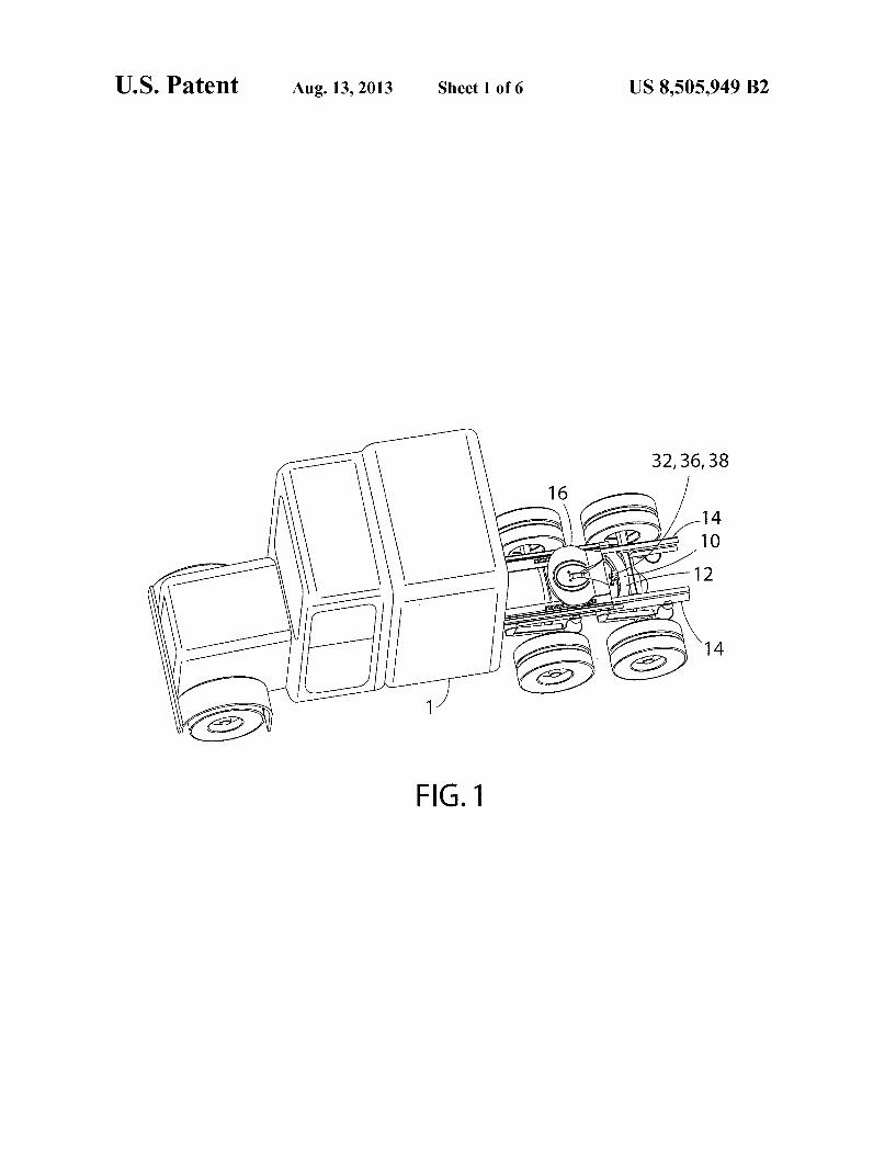
FIG. 1 is an isometric view of a tractor including compo nents of an automated tractor-trailer coupler system Sup ported by a frame assembly:
FIG. 2 is a partially fragmentary top plan view of a portion of a tractor frame assembly and a curved automatic coupler track, multi-function connector housing, and mating pinion of the tractor-trailer coupler system of FIG. 1;
FIG. 2A is a cross-sectional view taken along the line IIA-IIA of FIG. 2;
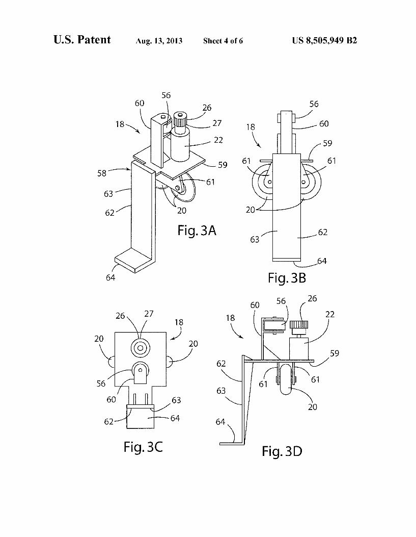
FIG. 3A is a perspective view of a movable cart that is configured to move along the track, wherein an associated outer cart housing has been removed;
FIG. 3B is a rear elevational view of the cart of FIG. 3A; FIG. 3C is a top plan view of the cart of FIG. 3A: FIG. 3D is a side view of the cart of FIG. 3A; FIG. 4 is an isometric view of the automatic coupler track,
multi-function connector housing and a linear pneumatic actuator,
FIG. 5 is a partially fragmentary isometric view of the components of the coupler system that are mounted to a trailer;
FIG. 6 is an isometric view of a trailer-mounted receptacle receiver; and
FIG. 7 is a system operation flow diagram.
DETAILED DESCRIPTION OF THE PREFERRED EMBODIMENT
With reference to FIGS. 1 and 2, a tractor-trailer coupling system 10 according to one aspect of the present invention provides for automatic and/or remotely-controlled powered coupling of electrical and pneumatic systems of a vehicle tractor 1 to the electrical and pneumatic systems of a trailer 39 (FIG. 5). Coupling system 10 includes a curved track 12 mounted to frame rails 14 of tractor 1 behind a fifth wheel assembly 16. As described in more detail below, in use, tractor 1 and trailer 39 are first mechanically coupled together uti lizing a known fifth wheel hitch assembly 16 on tractor 1 and a kingpin 50 on trailer 39. Controller 2 of system 10 then causes a cart 18 to move along curved track 12 until electrical and pneumatic connectors or plugs 38 and 36 (FIG. 2A), respectively, on cart 18 are positioned directly below corre sponding plugs or connectors 38A and 36A of a plug or connector 85 on trailer 39, at which point cart 18 stops. A pneumatic cylinder 30 is then extended to cause plugs 38 and 36 to engage corresponding plugs 38A and 36A, respectively, to thereby operably interconnect the electrical and pneumatic systems of tractor 1 and trailer 39. The pneumatic cylinder is then retracted and cart 18 is moved along curved track 12 to return cart 18 to a home or starting position. As also described in more detail below, track 12 is preferably mounted as close to the fifth wheel assembly 16 as possible to allow for mis alignment between tractor 1 and a trailer 39 (FIG. 5) during coupling of a tractor 1 to a trailer 39.
With reference to FIGS. 2 and 2A, movable support assem bly or cart 18 is movably mounted inside housing 45 of curved track assembly 12. Housing 45 of curved track assembly 12 includes a plate-like base 46, curved inner and outer sidewalls 47 and 48, respectively, and a removable top plate 49 that may be secured to the side walls 47 and 48 utilizing bolts 50 or other suitable fasteners. A pair of upright webs or walls 51 and 52 are welded or otherwise secured to base 46. The curved wall sections 51 and 52 define an upwardly-opening curved channel or slot 53 that receives rollers or wheels 20 (see also FIGS. 3 A-D) of cart assembly 18. The curved channel 53 has

US 8,505,949 B2 3
a radius corresponding to the curvature of housing 45. Curved channel 53 has a radius “R1” (FIG. 2) about a vertical axis 5 corresponding to the location of kingpin 50 of trailer 39 when tractor 1 and trailer 39 are mechanically coupled. A curved rack 24 having a plurality of teeth 25 is mounted
to a curved wall or web 54 having a radius about vertical axis 5 that is slightly greater than radius R1 of curved channel 53. The opposite ends of rack 24 and/or curved web 54 may be welded or otherwise secured to ends 55 (FIG. 4) of housing 45 Such that the central portion of rack 24 is not connected to housing 45. Alternately, web 54 and rack 24 may optionally be interconnected with a top plate 49 of housing 45, base 46, or other structure as required. Cart 18 includes an electric motor 22 (FIG. 2A) that drives a pinion gear 26 having a plurality of teeth 27 that engage teeth 25 of rack 24. As discussed in more detail below, actuation of electric motor 22 causes cart 18 to move along rack 24, with wheel 20 support ing at least a portion of the weight of cart 18 in curved channel 53. A wheel or roller 56 engages web 54 opposite teeth 25 of rack 24 to ensure that pinion gear 26 remains in engagement with rack 24.
With further reference to FIGS. 3A-3D, cart 18 includes a bracket or cart structure 58 including a horizontal plate or web 59. Wheel 56 is rotatably mounted to an upwardly-extending support or structure 60, and wheels 20 are rotatably mounted to Support plates 61 for rotation about generally horizontal axes. The support plates 61 are welded or otherwise secured to horizontal plate 59. Cart 18 includes an actuator mount 62 for mounting a linear actuator Such as pneumatic cylinder 30. Actuator mount 62 includes a vertically extending plate 63 and a horizontal plate or pad 64.
Referring again to FIG. 2A, cart 18 may include a wheel 66 that is rotatably mounted to a support structure 65 of cart 18 for rotation about a generally vertical axis. Wheel 66 is in rolling contact with convexly-curved inner surface 67 of inside wall 47 of housing 45. Cart 18 may also include upper and lower external wheels 69 and 70, respectively, that are mounted to a vertical plate structure 68 of cart 18 (see also FIG. 4). Upper wheel 69 engages a concavely-curved exterior surface 71 of inner side wall 47 of housing 45, and wheel 70 engages concavely-curved lower exterior Surface 72 of inner side wall 47 of housing 45. A portion of horizontal plate 59 of cart 18 extends through an elongated slot 73 formed in side wall 47 of housing 45, such that wheels 69 and 70 of cart 18 are positioned exterior of housing 45. Wheels 20, 56,66, gear 26, electric motor 22, and other components of cart 18 are positioned in interior space 75 of housing 45. Exterior wheels 69 and 70 are optional, and they are therefore not shown in FIGS. 1, 2, and 3A-3D.
Referring again to FIGS. 2A and 4, a linear powered actua tor, Such as a pneumatic cylinder 30, is mounted to vertical plate 68 of cart 18. Pneumatic cylinder 30 is connected to lines or conduits 31 that supply pressurized air from the vehicle's air supply (not shown) to provide for powered actuation of pneumatic cylinder 30. Solenoid-powered valves (not shown) control flow of pressurized air to cylinder 30 to control extension and retraction of cylinder 30. Alternately, pneumatic cylinder 30 may be mounted to actuator mount 62 if cart 18 is constructed according to the embodiment of FIGS 3A-3D. A multi-function connector assembly 34 is detachably con
nected to a connection box 79 that is connected to rod or rods 78 of pneumatic cylinder 30. Multi-function connector assembly 34 includes a downwardly-extending male connec tor 80 that detachably engages a connector 81 of connection box. 79 to form a powered lock that selectively locks connec tor 34 to connection box 79 to ensure that connector 34 does
5
10
15
25
30
35
40
45
50
55
60
65
4 not become detached from box 79/cylinder 30 except during coupling operations as described below. Male connector 80 of multi-function connector 34 may comprise a cylindrical pin having an enlarged disc-like end 115. A powered actuator such as a solenoid 116 is mounted inside connection box 79 to cause a connector 117 to shift in a horizontal direction. Con nector 117 may comprise a pair of extensions having a U-shaped slot or opening that fits closely around male con nector 80 above disc-like end 115 to prevent upward move ment of multi-function connector 34 relative to connection box. 79 when connector 117 is in an extended or locked position. Also, male connector 80 may have non-circular (e.g. square) cross-sectional shape, and female connector 81 may be configured to retain connector 80 and housing 32 at a selected angular orientation relative to box 79. Also, cylinder 30 may include a pair of rods 78 to prevent rotation of housing 32 and connector 34 relative to cart 18. Connector 117 is retracted or disengaged upon actuation of Solenoid 116 to thereby permit multi-function connector 34 to be discon nected from connection box 79. System 10 also includes a proximity sensor or Switch (not shown) that signals when/if connector 80 is positioned in engagement with female con nector 81. In use, after multi-function connector 34 is con nected/locked to connector 85, solenoid 116 is actuated to retract connector 117, and pneumatic cylinder 30 is retracted to thereby move connection box 79 down and away from multi-function connector 34. Connector assembly 34 does not become disconnected from connection box 79 if tractor 1 is driven by itself (i.e., without being connected to a trailer 39). Connection box 79 is secured to rod(s)78 of cylinder 30 by threaded fasteners, welding, or other secure arrangement to ensure connection box 79 does not detach from rod(s) 78. Multi-function connector 34 includes a housing 32 and two male air nozzles 36 that can be detachably interconnected with corresponding female air connectors 36A of a connector 85 mounted to trailer 39 inside a housing 42. The connectors 36 and 36A may comprise known quick-disconnect connec tors that are similar to connectors utilized for pneumatic tools or the like, or the connectors 36 and 36A could comprise other Suitable connectors providing detachable interconnection of air lines to one another. The male connectors 36 are fluidly connected to pneumatic lines 82. Lines 82 provide pressur ized air from the pneumatic system of tractor 1 to operate the brakes of the trailer 39. Lines 82 preferably include a plurality of coils 83 to provide for extension and retraction of lines 82 upon movement of multi-function connector 34 relative to tractor 1.
Referring again to FIG. 2A, multi-function connector 34 also includes an electrical plug or connector 38 that is con figured to detachably interconnect with a corresponding elec trical connector 38A of plug or connector 85 of trailer 39. In the illustrated example, electrical connectors 38 and 38A comprise an industry standard (SAE J560) male 7-pin elec trical plug connector. Electrical lines 86 are electrically con nected to the electrical system of the tractor 1.
Multi-function connector 34 also includes a mechanical guide/locating structure such as a plurality of tapered pins 40 that extend upwardly from housing 32. The four tapered pins 40 are configured to be received in circular openings 40A of connector 85 of trailer 39. Openings 40A preferably have a diameter that is slightly larger than pins 40 to provide for a sliding interconnection that ensures that pneumatic connec tors 36 and electrical connectors 38 are properly aligned when multi-function connector 34 engages plug or connector 85 of trailer 39.
System 10 may also include a powered lock 118 (FIG. 2A) that mechanically interconnects connector assembly 34 to

US 8,505,949 B2 5
connector 85 to ensure that connectors 36, 36A and 38, 38A are not inadvertently disconnected. Powered lock 118 includes a pair of solenoids 119 mounted to connector 85/housing 42. Solenoids 119 selectively shift locking mem bers or pins 120 into engagement with openings 121 of con nector assembly 34. As discussed in more detail below, in use, solenoids 119 initially retain pins 120 in a retracted position. After connector assembly 34 is brought into engagement, with connector 85, solenoids 119 are actuated to shift pins 120 into engagement with openings 121, thereby securely locking connector 34 to connector 85. Solenoid 116 is then retracted to permit connector assembly 34 to be detached from connector box 79 upon retraction of cylinder 30.
With further reference to FIGS. 5 and 6, housing 42 com prises a box-like structure including generally upright or ver tical side walls 87, 88, and 89, and a sloped or angled front side wall 90. A horizontal plate 91 is connected to the side walls 87-90. A plurality of vertical ribs 92 provide support for plate 91. Housing 42 may be made from steel plate sections that are welded together. During coupling of tractor 1 to trailer 39, the tractor 1 may initially be misaligned relative to trailer 39, such that fifth wheel assembly 16 of tractor 1 or other portions of tractor 1 come into contact with receptacle receiver housing 42. If such contact occurs, sloped side wall 90 of housing 42 will tend to deflect trailer 39 upwardly, thereby preventing damage to housing 42 and/or other com ponents of the tractor 1 and trailer 39. An opening 95 in plate 91 of housing 42 (see also FIG. 2A) provides clearance whereby multi-function connector 34 can engage connector 85. Connector 85 may comprise a square tube-like structure 96 having an opening 97 that is square or rectangular. Thus, opening 97 has a shape that is substantially similar to housing 32 of multi-function connector 34 whereby housing 32 can fit inside opening 97. Openings 40A may be formed in a hori Zontal plate 98 disposed in tube-like structure 96. Plate 98 may be welded inside tube-like structure 96 at an intermediate position. Pneumatic connectors 36A and electrical connector 38A may be mounted to plate 98 of connector 85. Pneumatic connectors 36A are operably connected to the air system (not shown) of trailer 39 by pneumatic lines extending from con nectors 36A. Similarly, electrical connector 38A is connected to the electrical system (not shown) of trailer 39 by electrical lines extending from connector 38A. When the tractor 1 and trailer 39 are operably coupled together, the electrical system of the trailer controls the trailer lights, and the pneumatic system of the trailer controls the brakes of the trailer. Con nector 85 is recessed within housing 42 such that it is pro tected from damage that could otherwise occur during cou pling of tractor 1 with trailer 39.
In use, cart 18 and multi-function connector 34 are initially in a home or rest position 'A' (FIG. 2) at one end of track 24. Tractor 1 is then moved toward trailer39, such that kingpin 50 of trailer 39 is mechanically coupled to fifth wheel connector assembly 16. Tractor 1 and trailer 39 may include an auto mated sensor system as disclosed in U.S. Pat. Nos. 6,452.485 and 6,285,278, each of which is incorporated herein by ref erence in their entirety. If the tractor 1 and trailer 39 include an automated sensor system, the automated sensor system may actuate coupler system 10 automatically upon indication of a positive coupling between kingpin 50 and fifth wheel assem bly 16. Alternately, the driver or other user may actuate cou pler system 10 after tractor 1 is connected to trailer 39 if the driver confirms that tractor 1 and trailer39 have been properly coupled. System 10 may include a switch (not shown) mounted in the cab of tractor 1 to provide for actuation of coupler system 10 if an automated sensor system is not uti lized.
10
15
25
30
35
40
45
50
55
60
65
6 Once tractor 1 and trailer 39 have been mechanically
coupled (step 100 in FIG. 7), system 10 is actuated (step 101 in FIG. 7). In general, trailer 39 may not be directly aligned with tractor 1 immediately following connection of kingpin 50 and fifth wheel assembly 16, such that connector 85 of trailer 39 is not disposed along a center line “C” (FIG. 2) of tractor 1. When cart 18 is in the home or rest position 'A'. pneumatic cylinder 30 is in a fully retracted position, such that multi-function connector 34 is spaced-apart from lower surface 99 (FIG.5) of trailer39, and multi-function connector 34 is positioned adjacent housing 45 to thereby prevent dam age to connector 34 during coupling of tractor 1 and trailer39.
After coupling of the tractor 1 and trailer 39, and after the system is triggered 101, pneumatic cylinder 30 is actuated (step 102 in FIG. 7) to raise multi-function connector 34 to an intermediate position that is higher than the home or start position, but wherein the multi-function connector 34 is posi tioned lower than plate 91 (FIG. 5) of housing 42. Alternately, trailer 39 may include a bolster plate (not shown) mounted to lower side 99 of trailer 39 that is substantially flush with plate 91, with the bolsterplate extending over and above the path of connector 34 along track 24. If trailer 39 includes a bolster plate, cylinder 30 can be actuated until the pins 40 contact the bolster plate. The system controller may be configured to determine that contact between pins 40 and the bolster plate has occurred when the pressure of air supplied to cylinder 30 rises sharply. The controller then closes the valve (not shown) supplying air to pneumatic cylinder 30. Alternately, the valve providing pressurized air to cylinder 30 may remain open, such that pins 40 are urged into contact with the bolster plate. Electric motor 22 is then actuated by the controller, causing cart 18 to move along rack 24. One or more sensors or Switches (not shown) are positioned on multi-function con nector 34. The sensors or Switches may comprise a proximity sensor, limit switch, or other suitable device. The sensor or Switch generates a signal when multi-function connector 34 is positioned directly below connector 45 on trailer 39. As dis cussed above, trailer 39 may be positioned at a non-zero angle relative to tractor 1 about vertical axis 5. Accordingly, cart 18 and multi-function connector 34 will stop at different loca tions along rack 24, depending upon the position of trailer 39 relative to tractor 1. In general, the cart 18 causes multi function connector 34 to travel along an arc defined by the radius “R” (FIG. 2) about vertical axis 5. The sensing/detect ing of connector 85 is generally designated 104 in FIG. 7.
After the cart 18 stops with multi-function connector 34 in alignment with connector 85, pneumatic cylinder 30 is actu ated to thereby raise multi-function connector 34, causing pins 40 to engage openings 40A (FIG. 2A) and also causing pneumatic connectors 36 to connect to the corresponding female pneumatic connectors 36A. If trailer 39 includes a bolster plate (not shown), pins 40 will slide along the bolster plate until pins 40 are aligned with opening 95 in plate 91 of housing 42. Once the pins 40 are aligned with opening 95, pneumatic cylinder 30 will tend to cause connector 34 to move upwardly somewhat due to the air pressure in pneu matic cylinder 30. A sensor (not shown) may be utilized to detect the drop in air pressure, and the controller may be configured to interpret the pressure drop as a signal that the connector 34 is aligned with connector 85. Similarly, actua tion of pneumatic cylinder 30 causes electrical connector 38 of multi-function connector 34 to connect to the correspond ing connector 38A of connector 85. Alternately, if the valve Supplying pressurized air to cylinder 30 remains open as cart 18 moves, cylinder 30 will extend automatically once pins 40 are aligned with opening 95 in housing 42.

US 8,505,949 B2 7
As discussed above, system 10 may also include a powered mechanical plug locking device 118 that mechanically inter connects multi-function connector 34 to connector 85 to ensure that multi-function connector 34 does not become disconnected when tractor 1 is pulling trailer 39 on a road surface or the like. After the pneumatic cylinder 30 is extended to cause interconnection of multi-function connec tor 34 with connector 85, the plug lock 118 is actuated to thereby lock multi-function connector 34 to connector 85.
Airlines 82 are charged (pressurized) after a sensor (not shown) indicates that connector 34 has been properly con nected to connector 85. Pneumatic cylinder 30 then retracts, causing the multi-function connector 34 to disengage from the connector box 79, leaving connector 34 connected to connector 85. The cart 18 is then moved back to its parked or home position 'A' out of the way of any moving parts on the truck and trailer, e.g. near a frame rail 14. Finally, a signal is sent to a visual indicator (e.g. light) or audible indicator in the tractor cab indicating a positive connection.
To decouple tractor 1 from trailer39, system 10 operates in substantially reverse order from the sequence described above and shown in FIG. 7. System 10 may be configured to require a manual input from a user to decouple tractor 1 from trailer 39.
System 1 includes a controller that is programmed to pro vide operation according to the sequence of FIG. 7. The controller is operably connected to sensors and actuators, and system 10 operates according to the following conditions and Sequences: Starting Conditions:
1. Solenoid valve controlling extension of pneumatic cyl inder—closed
2. Solenoid valve controlling retraction of pneumatic cyl inder—closed
3. Pneumatic and electrical connector lock(s)/solenoid (s)—retracted/unlocked
4. Electric motor power disabled . Multi-function connector to connection box solenoid/ lock—extended/locked
Coupling Sequence: 1. Receive (optional) signal from kingpin/fifth wheel mat
ing sensor system 2. Operator push button pressed to activate coupling
Sequence 3. Solenoid valve controlling extension of pneumatic cyl
inder opens, causing pneumatic cylinder to extend par tially
4. Electric motor actuated, causing cart to move along track/rack
5. Pressure sensor senses pressure drop at instant cylinder begins to extend into opening of housing on trailer
. Motor deactivates, cart stops
. Plug proximity sensor senses plugs mated
. Plug lock Solenoids extend to lock male/female connec tors together
9. Solenoid retracts to unlock connector block from con nection block/pneumatic cylinder
10. Solenoid valve controlling extension of pneumatic cyl inder closes and retract pneumatic cylinder Solenoid valve opens
11. Pressure sensor senses pressure increase when cylinder is retracted
12. Solenoid valve controlling retraction of pneumatic cyl inder closes
13. Electric motor drives reverse to return cart to rest/start position adjacent end of curved track
14. ProXimity sensor signals cart returned to start position
5
10
15
25
30
35
40
45
50
55
60
65
8 15. Electric motor power disabled to stop cart at start posi
tion 16. Plug coupled indicator (in vehicle cab) enabled
Driving Conditions: 1. Solenoid valve controlling extension of pneumatic cyl
inder closed 2. Solenoid valve controlling retraction of pneumatic cyl
inder closed 3. Pneumatic and electric lock or locks extended to lock
connector to trailer 4. Electric motor power disabled 5. Connector block to pneumatic cylinder lock retracted/
unlocked Uncoupling Sequence:
1. Operator push button pressed to activate decoupling Sequence
2. Solenoid valve opens to extend cylinder, causing con nector box on cylinder to contact bolster plate on trailer
3. Electric motor drives cart forward 4. Plug base proximity sensor senses multi-function con
nector engaged with connection box on pneumatic cyl inder
. Electric motor deactivates to stop cart 6. Solenoid extends to lock multi-function connector to
connector box 7. Solenoids retract to unlock multi-function connector
from trailer 8. Solenoid valve controlling extension of pneumatic cyl
inder closes and Solenoid controlling retraction of pneu matic cylinder opens
9. Pressure sensor senses pressure increase when pneu matic cylinder is retracted
10. Solenoid valve controlling retraction of pneumatic cyl inder closes
11. Electric motor drives reverse direction 12. Return proximity sensor signals that cart has returned
to home or start position 13. Electric motor power disabled 14. Plug decoupled indicator (in vehicle cab) enabled The coupling system 10 may be installed at the time the
tractor 1 and trailer 39 are manufactured, or the system 10 may be retrofitted to existing tractors 1 and trailers 39. Curved track 12 may be configured to be mounted (e.g., welded or mechanically fastened) to existing tractor frames, and hous ing 42 may be configured to be mounted to existing trailers.
These and other aspects, objects, and features of the present invention will be understood and appreciated by those skilled in the art upon studying the following specification, claims and attached drawings.
5
What is claimed is: 1. A coupling system for operably interconnecting at least
one of an electrical system and a pneumatic system of a road tractor to a trailer when the road tractor and the trailer are connected together by a fifth wheel assembly and a kingpinto define a generally vertical pivot axis, the coupling system comprising:
a curved track configured to be mounted to a frame of a road tractor,
a cart structure movably connected to the curved track for powered movement along a generally horizontal curved path;
a connector assembly movably and releasably connected to the cart structure for powered movement in a direction that is transverse to the curved path, the connector assembly including at least one of a first electrical con nector configured to be connected to an electrical system

US 8,505,949 B2
of a road tractor and a first pneumatic connector config ured to be connected to a pneumatic system of a road tractor,
at least one of a second electrical connector configured to be electrically coupled to an electrical system of a trailer and a second pneumatic connector configured to be con nected to a pneumatic brake system of a trailer; and wherein:
in use the one second electrical connector or second pneu matic connector are mounted to a trailer, and, after con nection of a trailer kingpin to a fifth wheel assembly, the cart moves from a first position along the curved path until the connector assembly is positioned in registry with the one second electrical connector or second pneu matic connector, followed by movement of the connec tor assembly relative to the cart structure to couple the one first electrical or pneumatic connector to the one second electrical or pneumatic connector whereby at least one of a tractor electrical and pneumatic system is operably coupled to at least one of a trailer electrical and pneumatic system, respectively, and wherein the con nector assembly disconnects from the cart structure after coupling of the electrical or pneumatic connectors.
2. The coupling system of claim 1, wherein: the connector assembly includes both the first electrical
connector and the first pneumatic connector, and wherein the coupling system includes both the second electrical connector configured to be electrically coupled to an electrical system of a trailer and the second pneumatic connector configured to be connected to a pneumatic brake system of a trailer.
3. The coupling system of claim 2, wherein: the connector assembly is releasably connected to the cart
structure such that the cart structure can be disconnected from the connector assembly and moved away from the connector assembly after the first and second electrical connectors are interconnected and after the first and second pneumatic connectors are interconnected.
4. The coupling system of claim 1, including: an electric motor providing powered movement of the cart
structure along the curved path. 5. The coupling system of claim 4, wherein: the electric motor is mounted to the cart structure. 6. The coupling system of claim 5, wherein: the curved track includes a curved rack having a plurality of
teeth positioned to define an arc, and wherein: the electric motor drives a pinion gear that engages the
teeth of the curved rack to move the cart structure along the curved path.
7. The coupling system of claim 6, wherein: the curved track defines at least one upwardly-facing Sup
port Surface extending along the track; and including: at least one roller mounted to the cart structure to movably
Support the cart structure on the upwardly-facing Sup port Surface.
8. The coupling system of claim 1, including: a linear actuator mounted to the cart structure and provid
ing Substantially linear movement of the connector assembly relative to the cart structure.
9. The coupling system of claim 8, wherein: the linear actuator comprises a pneumatic cylinder that
causes the connector assembly to move in a Substantially vertical direction relative to the cart structure.
10. The coupling system of claim 1, wherein: the curved path comprises an arc defining a center at the
Vertical pivot axis.
10
15
25
30
35
40
45
50
55
60
65
10 11. A coupling system for operably interconnecting at least
one of an electrical system and a pneumatic system of a road tractor to a trailer when the road tractor and the trailer are connected together by a fifth wheel assembly and a kingpinto define a generally vertical pivot axis, the coupling system comprising:
a curved track defining at least one upwardly-facing Sup port Surface extending along the track, the curved track configured to be mounted to a frame of a road tractor, the curved track including a curved rack having a plurality of teeth positioned to define an arc:
a cart structure movably connected to the curved track for powered movement along a generally horizontal curved path;
at least one roller mounted to the cart structure to movably Support the cart structure on the upwardly-facing Sup port structure;
an electric motor providing powered movement of the cart structure along the curved path, wherein the electric motor is mounted to the cart structure, and wherein the electric motor drives a pinion gear that engages the teeth of the curved rack to move the cart structure along the curved path;
a connector assembly movably connected to the cart struc ture for powered movement in a direction that is trans verse to the curved path, the connector assembly includ ing at least one of a first electrical connector configured to be connected to an electrical system of a road tractor and a first pneumatic connector configured to be con nected to a pneumatic system of a road tractor;
at least one of a second electrical connector configured to be electrically coupled to an electrical system of a trailer and a second pneumatic connector configured to be con nected to a pneumatic brake system of a trailer; and wherein:
in use the one second electrical connector or second pneu matic connector is mounted to a trailer, and, after con nection of a trailer kingpin to a filth wheel assembly, the cart moves from a first position along the curved path until the connector assembly is positioned in registry, with the one second electrical connector or second pneu matic connector, followed by movement of the connec tor assembly relative to the cart structure to couple the one first electrical or pneumatic connector to the one second electrical or pneumatic connector whereby at least one of a tractor electrical and pneumatic system is operably coupled to at least one of a trailer electrical and pneumatic system, respectively;
the curved track defines a channel having a curved shape in plan view, and the upwardly-facing Support Surface comprises a base surface of the curved channel whereby the roller is at least partly disposed in the curved chan nel.
12. The coupling system of claim 11, including: a housing defining an interior space; and wherein: at least a portion of the cart structure and the curved rack
are disposed in the interior space. 13. The coupling system of claim 12, wherein: the housing defines a sidewardly-facing curved surface; the one roller comprises a first roller; and including: a second roller mounted to the cart Surface in rolling con
tact with the sidewardly-facing curved surface. 14. The coupling system of claim 13, wherein: the sidewardly-facing curved surface comprises a concave
exterior Surface of the housing and wherein the second roller is disposed outside of the housing.

US 8,505,949 B2 11
15. In a tractor-trailer having a tractor that includes elec trical and pneumatic systems, and a trailer having a kingpin and electrical and pneumatic systems, and wherein the tractor includes a fifth wheel hitch assembly that couples to the kingpin and provides pivotable movement of the trailer rela tive to the tractor, the improvement comprising:
a coupling system for coupling the electrical and pneu matic systems of the tractor to the electrical and pneu matic systems of the trailer, respectively, the coupling System comprising:
a cart structure movably mounted to the tractor for move ment along a curved path;
a powered actuator that moves the cart structure along the curved path upon actuation of the powered actuator;
a connector assembly including a first electrical connector and a first pneumatic connector, wherein the connector assembly is detachably and movably interconnected to the cart structure;
a second electrical connector attached to the trailer; a second pneumatic connector attached to the trailer; and
wherein: the cart structure moves along the curved path upon actua
tion of the powered actuator and the connector assembly moves relative to the cart structure to thereby intercon nect the first and second electrical connectors and the first and second pneumatic connectors to operably inter connect the electrical and pneumatic systems of the trac tor and the trailer, and wherein the connector assembly detaches from the cart structure after the first and second electrical connectors are interconnected and after the first and second pneumatic connectors are intercon nected.
16. The tractor-trailer of claim 15, including: a curved guide structure mounted to the trailer, and
wherein: the cart structure is movably connected to the curved guide
Structure. 17. The tractor-trailer of claim 16, wherein: the trailer pivots about a generally vertical pivot axis rela
tive to the tractor; and the curved guide structure forms an arc about the pivotaxis. 18. The tractor-trailer of claim 17, wherein: in use, the cart structure moves along the curved path and
stops when the connector assembly is positioned adja cent the second electrical and pneumatic connectors;
the connector assembly moves relative to the cart structure after the cart structure stops to couple the first and sec ond electrical connectors and the first and second pneu matic connectors.
19. The tractor-trailer of claim 17, including: an electric motor providing powered movement of the cart
structure along the curved path. 20. The tractor-trailer of claim 15, including: a protective housing mounted to a lower side of the trailer;
and wherein: the second electrical connector and the second pneumatic
connector are mounted to the trailer and disposed inside the protective housing.
21. The tractor-trailer of claim 20, wherein: the housing defines a downwardly-facing lower surface
and an opening in the lower surface; and wherein: the second electrical and pneumatic connectors are posi
tioned in Vertical registry with the opening. 22. In a tractor-trailer having a tractor that includes elec
trical and pneumatic systems, and a trailer having a kingpin and electrical and pneumatic systems, and wherein the tractor
5
10
15
25
30
35
40
45
50
55
60
65
12 includes a fifth wheel hitch assembly that couples to the kingpin and provides pivotable movement of the trailer rela tive to the tractor, wherein the trailer pivots about a generally vertical pivot axis relative to the tractor, the improvement comprising:
a coupling system for coupling the electrical and pneu matic systems of the tractor to the electrical and pneu matic systems of the trailer, respectively, the coupling System comprising:
a curved guide structure mounted to the trailer; a cart structure movably mounted to the tractor for move
ment along a curved path, wherein the cart structure is movably connected to the curved guide structure, and the curved guide structure forms an arc about the pivot axis and wherein opposite ends of the curved guide structure are rigidly attached to frame rails of the tractor;
a connector assembly including a first electrical connector and a first pneumatic connector, wherein the connector assembly is movably interconnected to the cart struc ture;
a second electrical connector attached to the trailer; a second pneumatic connector attached to the trailer; and
wherein: the cart structure moves along the curved path and the
connector assembly moves relative to the cart structure to thereby interconnect the first and second electrical connectors and the first and second pneumatic connec tors to operably interconnect the electrical and pneu matic systems of the tractor and the trailer; and
opposite ends of the curved guide structure are rigidly attached to frame rails of the tractor.
23. A method of retrofitting an existing tractor-trailer Vehicle with a coupling system that operably interconnects electrical and pneumatic systems of a tractor and a trailer upon hitching a trailer to a tractor utilizing a fifth wheel hitch and kingpin: the method comprising:
mounting a curved guide structure to a frame of a tractor; providing a cart structure that is movably connected to the
guide structure for movement of the cart structure along a curved path;
providing a connector assembly that is detachably and movably connected to the cart structure, wherein the connector assembly includes a first electrical connector and a first pneumatic connector;
ensuring that the first electrical connector is connected to an electrical system of a tractor;
ensuring that the first pneumatic connector is connected to a pneumatic system of a tractor;
mounting second electrical and pneumatic connectors to a trailerata location that is horizontally spaced-apart from a kingpin of the trailer;
ensuring that the second electrical connector is connected to an electrical system of the trailer;
ensuring that the second pneumatic connector is connected to a pneumatic system of the trailer; and
configuring the coupling system such that the cart structure moves along the curved path and the connector assembly moves to interconnect the first and second electrical and pneumatic connectors;
wherein the connector assembly detaches from the cart structure while the first and second electrical and pneu matic connectors are interconnected such that the cart structure can be moved relative to the first and second electrical and pneumatic connectors.
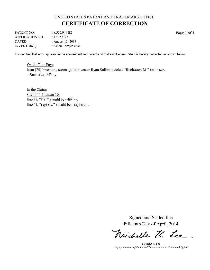
UNITED STATES PATENT AND TRADEMARK OFFICE
CERTIFICATE OF CORRECTION
PATENT NO. : 8,505,949 B2 Page 1 of 1 APPLICATIONNO. : 12/758173 DATED : August 13, 2013 INVENTOR(S) : Kevin Temple et al.
It is certified that error appears in the above-identified patent and that said Letters Patent is hereby corrected as shown below:
On the Title Page Item 75 Inventors, second joint inventor Ryan Sullivan; delete “Rochester, MI and insert --Rochester, MN--
In the Claims Claim 11 Column 10
line 39, “filth' should be-fifth line 41, “registry, should be --registry--.
Signed and Sealed this Fifteenth Day of April, 2014
74-4-04- 2% 4 Michelle K. Lee
Deputy Director of the United States Patent and Trademark Office


![United States Patent [19] Patent ... - Tourniquet Educationtourniquets.org/wp-content/uploads/OurPatents/McEwen-Pneumatic...A pneumatic tourniquet includes an inflatable cuff, a pressurizing](https://img.dokumen.tips/doc/110x75/5b0b9b5a7f8b9ae61b8e25f7/united-states-patent-19-patent-tourniquet-pneumatic-tourniquet-includes.jpg)


![Home [] · Testimonials Trailer Delivery Horse Trailer Blog Horse Trailer Buying Guide Horse Trailer Lingo Horse Trailer Maintenance Trailering Safety Search Inventory OR enter Trailer#:](https://img.dokumen.tips/doc/110x75/5f60b857e51db4230831ff65/home-testimonials-trailer-delivery-horse-trailer-blog-horse-trailer-buying-guide.jpg)


