Embed Size (px)
Citation preview

MASTER
CONTROLLER
/30
mu uuuu ui iiui iiui mil lull iuu um uiii iuu iuui uu uii mi
(12) United States PatentEllerbrock et al.
(54) NETWORK DEVICE INTERFACE FORDIGITALLY INTERFACING DATACHANNELS TO A CONTROLLER VIA ANETWORK
Inventors: Philip J. Ellerbrock, Bridgeton, MO(US); Robert L. Grant, St. Peters, MO(US); Daniel W. Konz, Hazelwood, MO(US); Joseph P. Winkelmann, St.Peters, MO (US)
Assignee: The Boeing Company, Seattle, WA(US)
Notice: Subject to any disclaimer, the term of thispatent is extended or adjusted under 35U.S.C. 154(b) by 35 days.
Appl. No.: 11/852,706
Filed: Sep.10, 2007
Prior Publication Data
US 2008/0172506 Al Jul. 17, 2008
Related U.S. Application Data
Division of application No. 10/726,918, filed on Dec.3, 2003, now Pat. No. 7,277,970, which is a division ofapplication No. 09/735,146, filed on Dec. 12, 2000,now Pat. No. 6,708,239.Provisional application No. 60/254,136, filed on Dec.8, 2000.
Int. Cl.G06F 3100 (2006.01)U.S. Cl . ........................................... 710/61; 710/69Field of Classification Search ................... 710/58,
710/60-62, 64, 69, 72-74; 341/70; 345/333,345/361; 370/419; 702/189; 709/224
See application file for complete search history.
(lo) Patent No.: US 7,552,256 B2(45) Date of Patent: Jun. 23, 2009
(56) References Cited
U.S. PATENT DOCUMENTS
4,124,778 A 11/1978 Amass
(Continued)
FOREIGN PATENT DOCUMENTS
EP 0 449 458 Al 10/1991
(Continued)
OTHER PUBLICATIONS
Infineon: C167CR 16-BIT Single-Chip Microcontroller; Apr. 2000;72 pages; XP-002201995; Published by Infineon Technologies AG.
(Continued)
Primary Examiner Khanh Dang(74) Attorney, Agent, or Firm Alston & Bird LLP
(57) ABSTRACT
A communications system and method are provided for digi-tally connecting a plurality of data channels, such as sensors,actuators, and subsystems, to a controller using a networkbus. The network device interface interprets commands anddata received from the controller and polls the data channelsin accordance with these commands. Specifically, the net-work device interface receives digital commands and datafrom the controller, and based on these commands and data,communicates with the data channels to either retrieve data inthe case of a sensor or send data to activate an actuator. Dataretrieved from the sensor is converted into digital signals andtransmitted to the controller. Network device interfaces asso-ciated with different data channels can coordinate communi-cations with the other interfaces based on either a transition ina command message sent by the bus controller or a synchro-nous clock signal.
16 Claims, 13 Drawing Sheets
(75)
(73)
(21)
(22)
(65)
(62)
(60)
(51)
(52)(58)
NETWORK CONTROLLER
XEANNEL CNANNER
36
CHANNEL CHANNEL
36
CrUCrUDATA DATA DATA DATA

US 7,552,256 B2Page 2
U.S. PATENT DOCUMENTS
4,304,001 A
12/1981 Cope
4,449,202 A
5/1984 Knapp et al .............. 710/310
4,688,168 A
8/1987 Gudaitis et al.
4,942,571 A
7/1990 M611er et al.
4,969,147 A
11/1990 Markkula, Jr. et al.
5,113,498 A
5/1992 Evan et al . ............... 710/8
5,138,709 A
8/1992 Jones et al.
5,251,208 A
10/1993 Canniff et al.
5,274,783 A
12/1993 House et al.
5,367,678 A
11/1994 Lee et al.
5,445,128 A
8/1995 Letang et al.
5,557,634 A
9/1996 Balasubramanian et al
5,615,404 A
3/1997 Knoll et al.
5,623,610 A
4/1997 Knoll et al.
5,694,555 A
12/1997 Morriss et al.
5,742,847 A
4/1998 Knoll et al.
5,754,780 A
5/1998 Asakawa et al.
5,809,027 A
9/1998 Kim et al.
5,815,516 A
9/1998 Aaker et al.
5,909,556 A
6/1999 Morriss et al.
5,946,215 A
8/1999 Mito
5,978,875 A
11/1999 Asano et al.
6,013,108 A
1/2000 Karolys et al.
6,134,485 A
10/2000 Tanielian et al.
6,195,724 B1
2/2001 Stracovsky et al.
6,273,771 B1
8/2001 Buckley et al.
FOREIGN PATENT DOCUMENTS
EP 0 562 333 A2 9/1993WO WO 99/63409 12/1999WO WO 00/62501 10/2000
OTHER PUBLICATIONS
Tobias Wenzel; Infineon: CAN Baudrate Detection with InfineonCANDevices; Jul. 1999, 11 pages; XP-002201996.PCT Notification of Transmittal of the International Search Report,PCT International Search Report for PCT/US02/13190 (filedApr. 26,2002).PCT Notification of Transmittal of the International Search Report,PCT International Search Report for PCT/US02/13246 (filedApr. 26,2002).
PCT Notification of Transmittal of the International Search Report,PCT International Search Report forPCT/US02/13303 (filedApr. 26,2002).PCT Notification of Transmittal of the International Search Report;PCT International Search Report for PCT/US02/ 13366.PCT Notification of Transmittal of the International Search Report,PCT International Search Report for PCT/US02/13367 (Filed Apr.26, 2002).PCT Communication Relating to the Results of the Partial Interna-tional Search for PCT/US/01/47393.Robert Patzke; Fieldbus basics; 1998; pp. 275-293; Computer Stan-dards & Interfaces 19 (1998); Elsiver Sciences B.V.Intersil; HE-15531 CMOS Manchester Encoder-Decorder; Internetarticle, Mar. 1997; XP002298816; available at <http://www.intersil.com/data/fn/fn296I > (visited Sep. 29, 1998).G.I. Gotlib, V. Ya. Zagurskii; Decoding Techniques in Coaxial-Cable-Based Local-Area Networks; 1989; pp. 47-54; vol. 23, No. 2;Automatic Control and Computer Sciences; Allerton Press, Inc.;Tobias Wenzel; CANBaudrate Detection withlnfineon CANdevices;Jul. 1997; 11 pages; Infineon Technologies; Microcontroller Divi-sion; XP002201996.IEEE Standard for a Smart Transducer Interface for Sensors andActuators—Transducer to Microprocessor Communication Proto-cols and Transducer Electronic Data Sheet (TEDS) Formats; Sep.1998; 122 pages; IEEE Instrumentation and Measurement Society;IEEE Std 1451.2-1997; ISBN 1-55937-963-4.European Search Report, Oct. 1, 2004 (Berlin).IEEE 1451: A Standard in Support of Smart Transducer Networking,Kang Lee, 2000 (from PTO-892 dated Apr. 4, 2006).Encoding Dictionary, Interfacebus.com (from PTO-892 dated Apr. 4,2006).Universal Asynchronous Receiver Transmitter Definition,Wikipedia.org (from PTO-892 dated Apr. 4, 2006).RS-232 Definition, Wikipedia.org (from PTO-892 dated Apr. 4,2006).RS-485, Innovatic.dk/knowledge/rs485/rs485.htm (from PTO-892dated Apr. 4, 2006).Philips' AN10250, 2004 (from PTO-892 dated Apr. 4, 2006).485 RS-Communication, datadog.com , 1998 (from PTO-892 datedApr. 4, 2006).EDN Access, edn.com, 1996 (from PTO-892 dated Apr. 4, 2006).
* cited by examiner

U.S. Patent Jun. 23, 2009 Sheet 1 of 13 US 7,552,256 B2
32
MASTER
30
CONTROLLER
36
NETWORK CONTROLLER
48 44 42
lop
R(VR XMTR XMTR
38 1^ 't I
NETWORK
BUS
50 52 46 50 5y 46
DATA (LOCK DATA
R(AVTARF
CLOCK UAiA
RCVR R(VR XMTR R(VR XMTR
qp 40
NDI DEVICE ----- NDIDEVI(E
34
34 SENSOR AQUATOR 36 SENSOR AQUATOR 36
DATA DATA DATA DATA
CHANNEL CHANNEL CHANNEL CHANNEL
f^a. 7.

U.S. Patent US 7,552,256 B2Jun. 23, 2009 Sheet 2 of 13
1^ START
BUS CONTROLLER SENDSDATA/COMMANDS
200
210
NDI DEVICE RECEIVESDATA/COMMAND
220
DATA/COMMANDS
NODESIGNATED FOR CONNECTED
DATA CHANNEL?
YES
230
ACQUIRE DATA OR COMMAND DATACHANNEL
CONVERT ANALOG DATA TODIGITAL DATA
CONVERT INTO PROPER FORMAT ANDTRANSMIT
END
fro. 2.
240
250

U.S. Patent Jun. 23, 2009 Sheet 3 of 13 US 7,552,256 B2
34 SENSORDATA
CHANNEL
ANALOG SIGNALIN
58ANALOGSIGNAL
CONDITIONING
62
SERIALPORT
ACTUATORDATA 36
CHANNEL
ANALOG SIGNALOUT
ANALOG60
SIGNALCONDITIONING
64
SERIALPORT
66
MEMORYDEVICE
40
INTERFACE
68LOCAL
OS[ILLATO
50
fOMMANDS/ARGUMENTS DATA
ONNEIWORKBUS RECEIVER
52
(LO(K ON NETWORK BUS (LOCKRECEIVER
DATA
46
TRANSMITTERDATA ON
NETWORK BUS
so. 3A.

U.S. Patent Jun. 23, 2009 Sheet 4 of 13 US 7,552,256 B2
SERIAL PORT 1 SERIAL PORT 270 72Ln N o
40-' ^_ ^VV VV^Q Q Q Q Q Q QQW 78 WWW WWW W
89N
80 `^NN 82 NN N
84
qp 88 IN-DATA REGISTER W 78h 1N-DATA REGISTER
AL
_LD
STACK DEPTH DATA STACK t= DATA STACK STACK DEPTH
8bJ
a
z 78a92 z N
STATUS REGISTER jS9TATUS REGISTER
79C Qw z ° N 79
74W as
° ^2 '- 76
oN
CDQ No a
DATA SERIAL SERIAL DATASELECT COMMAND/ COMMAND/ SELECTMUX CONTROL CONTROL MUX
94108
CLOCKBIT
DIVIDER
- WAKE102
CONTROL SLEEP
98LOGIC E-CAL
COMMAND DEVICE Z-CALDECODER INVENTORY DIVIDED CU(
100 SYNCHRONIZE
OUTPUT 106ADDRESS CONFIGURATION DATA
DECODER REGISTER MUX96
50 104
COMMANDS/ARGUMENTS DATA RECEIVER if TRANSMITTERDATA
NETWORK BUS CLOCKCLOCK RECEIVER LAJ 46
0 0 0 0 16-BIT PARALLEL
52 o PORT WITH WRITE°
oSTROBE
fro. 3B.
U.S. Patent Jun. 23, 2009 Sheet 5 of 13 US 7,552,256 B2
START
RECEIVE A TRIGGER AND READ Al
COMMAND
320
360
DECODE COMMAND AND ADDRESS
330
SHIFT CONTENTS OF IN-DATA
SEND CONVERT SIGNAL TODATA
REGISTER TO TOP OF STACK
CHANNEL
340
WAIT A SHORT TIME i
350
300
310
380
LOAD CONTENTS OF TOP OFSTACK TO TRANSMIT REGISTER
TRANSMIT CONTENTS OFTRANSMIT REGISTER
SERIAL TRANSFER WITH DATACHANNEL, PROGRAMMABLE
COMMAND GOESOUT ON MOSI, DATA RETURNEDON MISO, DATA RETURNED ON
MISO IS STORED IN IN-DATAREGISTER
END
^
fro 4.
400
420
430
440
10
flG S.
U.S. Patent Jun. 23, 2009 Sheet 6 of 13 US 7,552,256 B2

U.S. Patent Jun. 23, 2009 Sheet 7 of 13 US 7,552,256 B2
500
START
OPERATE INASYNCHRONOUS
MODE
CHECK THE SYNCHRONOUS CLOCKSIGNAL INPUT
530
510
NO.,Z1 ISASIGNAL YESPRESENT?
USE THESYNCHRONIZE
CLOCK SIGNAL TOCLOCK IN AND
OUT DATA
fln 6.
START
600MONITOR THE BITS TRANSMITTED BY
THE CONTROLLER
MONITOR COMMANDS FROM THEBUS CONTROLLER. USE SYNCHRONIZE
PATTERN LENGTH AND TIMEBETWEEN BITS FOLLOWING THECOMMAND SYN[HRONIZE TO
DETERMINE BIT RATE
SELEQ BIT RATE TO MATH THE BliRATE OF THE CONTROLLER
610
620
END
fly 7.

SECONDREGISTER
=1?
725
YES
750
YES AIS THIS TH80TH BIT? NO
790
,800
810
WIN
TRANSMIT NO. OF DATACHANNELS FROM TEDS
MEMORY WRITE ENABLE
READ NO. OF CHANNELS (OPT)ASSIGN LOGICAL ADDRESSES
ASSIGN GROUP MASKS
MOVE IDENTIFIEDBIT TO SECONDREGISTER ANDLOAD NEXT BIT
INTO FIRSTREGISTER
f^a 8.
U.S. Patent Jun. 23, 2009 Sheet 8 of 13 US 7,552,256 B2
NORMAL OPERATIONMODE
ENABLE)FBITCE INVENTORYMODE
705
UID WORDARCH MODE
710
EAST SIGNIFICANT FIRST REGISTER
720
A NO DROPOUT NOCOMMAND?
YES
NO
FIRST 730740 NO REGISTER
=1?TRANSMIT
UUID YESPULSE
760

LAJN C-,]
2
CL.d ^Z}- C:)c.n
V
U.S. Patent Jun. 23, 2009 Sheet 9 of 13
US 7,552,256 B2
`^L Lj
RC N © Z^dVCD
O V^p ^ QoC `^ Lon
^mm
H+on 2

U.S. Patent Jun. 23, 2009 Sheet 10 of 13 US 7,552,256 B2
0

U.S. Patent Jun. 23, 2009 Sheet 11 of 13 US 7,552,256 B2
NETWORK BUS 36
SYNCHRONOUSCLOCK SIGNAL
PROGRAMMABLE SYNCHRONIZE
(LOCK 116DIVIDER
108 DIVIDED(LOCK
DIGITIZED SAMPLEDATA 110
SUCCESSIVEAPPROXIMATION
A/D
SAMPLED ANALOGVALUE
SAMPLE & HOLD
FILTERED ANALOGSIGNAL
SIGNAL 114CONDITIONING
W1 TRUE ANALOGFILTERS
112
COMMANDS &DATA
COMMAND& 100&
ADDRESS 102DECODERS
wniCONVERT DEVICE
40
DATA CHANNEL
ANALOGSIGNAL
fro. 11A.

CONVERT I DEVICE40
108
DIVIDEDCLOCK
U.S. Patent Jun. 23, 2009 Sheet 12 of 13 US 7,552,256 B2
NETWORK BITS 38
SYNCHRONOUS
COMMANDS &CLOCK SIGNAL
DATA
PROGRAMMABLECLOCK
DIVIDER
SYNCHRONIZE124
COMMAND &ADDRESS
DECODERS
100 &102
DIGITIZED SAMPLEDATA 118
DIGITAL FILTER
DECIMATOR
HIGH SAMPLE RATEA/D DATA
ELTA A/D
FILTERED ANALOGSIGNAL
SIGNAL
122
CONDITIONINGW/ ANALOG ANTI-
ALIAS FILTERS
SI
120
DATA CHANNEL
ANALOGSIGNAL
so, 119.
U.S. Patent Jun. 23, 2009 Sheet 13 of 13 US 7,552,256 B2
NETWORK BUS 36
SYNCHRONOUS COMMANDS &
CLOCK SIGNAL DATA
PROGRAMMABLESYNC^$NIZE
COMMAND &CLOCK ADDRESS
DIVIDER DECODERS
108/(
DIVIDED
fLO(KfONVERT DEVICE
40
100 &102
DIGITIZED SAMPLEDATA 110
SUf(ESSIVEAPPROXIMATION --
A/D
SAMPLED ANALOGVALUE
SAMPLE &HOLD I----
FILTEREDANALOG112 SIGNAL
SIGNAL126
CONDITIONINGW/ SWITCHED
CAPACITOR FILTER
DATA CHANNEL
ANALOGSIGNAL
flG IIC.

US 7,552,256 B21
2NETWORK DEVICE INTERFACE FOR
to install and maintain. This is especially critical in aircraft
DIGITALLY INTERFACING DATA applications, where weight and size concerns are at the fore-CHANNELS TO A CONTROLLER VIA A
front. Further, in the automotive industry, the added wiring
NETWORK may add weight and cost to the car.5 Additionally, as stated, many conventional monitoring sys-
CROSS -REFERENCE TO RELATED
tems transmit data in an analog format. Typically, analogAPPLICATIONS
signals are susceptible to noise introduced into the signalsduring data transmission. Given that many of the transmitted
This application is a divisional of U.S. application Ser. No. signals have a low amplitude to start with, this noise can10/726,918, filed Dec. 3, 2003 now U.S. Pat. No. 7,277,970 io corrupt the signal and decrease the signal to noise ratio levelswhich is a divisional of U.S. application Ser. No. 09/735,146, that cause loss of resolution in the signal. Further, as many offiled Dec. 12, 2000, now U.S. Pat. No. 6,708,239 entitled: these remote devices are scattered a fair distance from theNetwork Device Interface For Digitally Interfacing Data controller, the electrical lines connecting the remote devicesChannels To A Controller Via A Network, which claims pri- to the controller may be sufficiently long to cause signalority from U.S. Provisional Patent Application No. 60/254, 15 degradation due to DC resistance in the wiring.136, filed on Dec. 8, 2000 having the same title, the contents
In light of this, it would be advantageous to replace the
of which are incorporated herein by reference.
dedicated wiring and the analog transmission with a commonbus and use digital transmission of data. But, many conven-
FEDERALLY SPONSORED RESEARCH OR
tional digital networks suffer from a variety of problemsDEVELOPMENT
20 themselves. For example, many existing digital networks
demand complicated protocols requiring processors and,This invention was made with government support under thus, forcing unacceptably large or costly remote devices.
Cooperative Agreement No. NCCW-0076 awarded by Processor based sensing devices may also have problemsNASA. The government has certain rights in this invention. taking samples of analog data, or causing an actuator to take
25 an action, at exactly the right time. Complicated protocolsFIELD OF THE INVENTION also introduce overhead into the messages on the bus that are
not necessary for data acquisition and control. This overheadThe present invention relates generally to network device can severely limit the number of data samples that can be
interface and, more particularly, to an apparatus and method
transmitted on the bus. These networks also have other prob-for digitally interfacing data channels with a controller over a 30 lems. For example, they generally do not support both acqui-common network bus. sition and control, and they typically only support short net-
work lengths. Further, these conventional networks typicallyBACKGROUND OF THE INVENTION
have bulky network device interfaces, slow network datarates, or a low network device count. Additionally, many
In many industries today, monitoring systems are used to 35 computer systems that include digital networks do not oper-assess either possible system failures or the affects of envi- ate in a time-deterministic manner. These computer systemsronment and other external forces on an object of interest. For generally lack the capability to schedule a trigger commandexample, in the avionics industry, monitoring systems are to the network components that repeats or is interpreted andemployed to monitor parameters, such as strains, accelera- executed with any precision timing.tion, pressures, corrosion, and temperatures at various critical 40 In light of the foregoing, it would be advantageous tostructural locations on aircraft. Similarly, such monitoring provide a network system that allows network components tosystems could be used in the automobile industry to control
digitally communicate over an inexpensive, simple and high-
and monitor everything from on/off occupant controls to speed, yet robust, network line with a simple, low overheaddrive-train controls and multimedia systems. message protocol, small component size and low wire count.
Many of these conventional monitoring systems use a plu- 45 The network system would also advantageously operate with-rality of remote devices, such as sensors, actuators, and sub- out the use of a microcontroller or processor for the networksystems that are placed about the object being monitored at
devices. Also, the network system would support both acqui-
the critical locations. Further, many of these conventional sition and control, and be capable of acquiring or convertingmonitoring systems include either one or several controllers data simultaneously from the networked components. Fur-connected to each of the remote devices for receiving data 50 ther, the network system would allow for high componentfrom the remote devices and sending commands to the remote counts, longer network lines and insure time determinism indevices. During operation, the controllers acquire data from a precise manner.the various sensors. The controllers also activate the actuatorsto perform functions on the object. SUMMARY OF THE INVENTION
Although these conventional monitoring systems provide a 55way to monitor critical structures of an object, they do have A brief definition of network objects here is necessary tosome drawbacks. For example, many of the conventional understand and avoid confusion in this specification. The firstmonitoring systems use dedicated wiring and signal condi- network object to be defined is the bus controller. The bustioning to connect each of the remote devices to the controller. controller is network device that sends commands on theAdditionally, many of the remote devices are typically ana- 6o network bus. All other devices on the network listen to the buslog, and data received from the remote devices is typically in controller and take actions based on the commands of the busanalog form. controller. A network device is any device on the network that
In many industries today, including the avionics and auto- is not a bus controller. A network device is often referred to asmotive industries, the complexity of the network may make a remote device throughout this disclosure. A Networkmany conventional monitoring systems impractical for a 65 Device Interface (NDI) is a component of a network device.number of reasons. Specifically, the dedicated wiring and
An NDI listens to the bus controller and any other traffic on
signal conditioning can be expensive, bulky, heavy and hard
the bus, and depending on the traffic on the network bus,

US 7,552,256 B23
performs an action or causes the network device to perform anaction. Most NDIs will be connected to at least one or moredata channels. A data channel is a sensor, an actuator, a sensorand signal conditioning, an actuator and signal conditioning,or other analog or digital system. A data channel is a compo- 5
nent of or is connected to the network device.As described in greater detail below, the present invention
remedies these and other problems by providing a networkdevice interface (NDI) for connecting various data channels,such as sensors, actuators, and subsystems, to a common 10
controller for transmission of commands and data to and fromthe data channels and the controller. Importantly, the NDIdevice of the present invention connects various data chan-nels to the controller via a common network, thereby permit-ting the various data channels to share the same wiring for 15
communicating with the controller. Further, the NDI of thepresent invention can interface to different types of data chan-nels, which can be analog-to-digital or digital-to-analog orother. Sensors are connected to the NDI as analog-to-digitaldata channels and actuators are connected to the NDI as 20
digital-to-analog data channels. The NDI of the presentinvention is capable of taking the digital data from an analog-to-digital channel, formatting it according to the proper pro-tocol, and transmitting it onto the network according to theprotocol. The NDI of the present invention is also capable of 25
taking digital data from the network, providing it as digitaldata to a Digital-to-Analog converter (D/A), and causing theD/A to convert the data to an analog signal. It is possible forother embodiments of the NDI to accept or produce analogsignals directly to and from its data channels. By transmitting 30
the data across the network in a digital format, the commandsand data are less susceptible to noise and degradation.
Further, the NDI device of the present invention operates inconjunction with a data protocol that allows the controller tocommunicate with either one or several network devices at a 35
time across the network. Importantly, the data protocol usedby the NDI device of the present invention has a fixed, low-level instruction set. Due to the simplicity of the protocol, theNDI device of the present invention is not required to be ahigh-level processor. Instead, in one preferred embodiment, 40
the NDI device of the present invention is a state machineimplemented as an Application Specific Integrated Circuit(ASIC). An advantage of using a state machine to implementthe NDI device instead of a micro-controller or processor isthat many processes can occur simultaneously, which aids the 45
NDI device to be time deterministic and fast.Advantageously, in one embodiment, the present invention
provides a network device interface capable of communicat-ing commands and data between a controller and a data chan-nel using either synchronous or asynchronous communica- 50
tion. In this embodiment, the NDI device includes a receiverfor receiving messages from the controller via the commondigital bus. The NDI device of this embodiment furtherincludes an interface for providing commands to the associ-ated data channel in response to messages received by the 55
receiver and for receiving data from the associated data chan-nel. Additionally, the NDI device includes a transmitter fortransmitting messages to the controller via the common digi-tal bus. Importantly, the NDI device further includes a syn-chronous network bus clock detector. 60
In operation, when data is received from the controller, theclock detector of the NDI device of the present inventiondetermines whether a clock signal accompanies the data fromthe controller. If a clock signal is present, then the controlleris communicating in synchronous mode. In this instance, the 65
NDI device uses the clock signal to provide commands anddata to and receive data from the data channel. Further, the
4transmitter of the NDI device of the present invention uses thebus clock signal to transmit data to the controller.
However, if the clock detector of the NDI device does notdetect a clock signal associated with the data sent from thecontroller, the NDI device determines that the bus controlleris operating in the asynchronous mode. In this instance, theNDI device provides commands and data to and receives datafrom the data channel in an asynchronous mode independentof a bus clock. Further, the transmitter of the NDI device ofthe present invention transmits data to the controller asyn-chronously independent of a bus clock in the synchronousmode.
In one embodiment, the controller provides synchronousclock signals via a common clock bus. In this instance, theclock detector of the present invention receives the synchro-nous clock signals and analyses the signals to determinewhether it is being sent at the same rate as the data bits. If so,the clock detector of the network device interface determinesthat the controller is operating in the synchronous mode.
Additionally, in some embodiments, the network deviceinterface of the present invention may further include a bitrate detector connected to the common digital bus. In thisembodiment, if the controller is operating in an asynchronousmode, the controller is transmitting commands and data at acertain bit rate. The bit rate detector of the present inventiondetects the bit rate, and the NDI device uses this bit rate tosend commands and data to the data channel and receive datafrom the data channel. Further, the transmitter of the presentinvention uses the detected bit rate to transmit data back to thecontroller.
In addition to transmitting data in an asynchronous mode ata defined bit rate, the controller may also alter the bit rateduring communication. In this embodiment, the controllermay initially transmit a first message to a data channel at apredetermined bit rate. In thi s embodiment, the clock detectorwill not detect a synchronous clock signal, but the bit ratedetector will detect the first bit rate at which the message istransmitted by the controller. Based on this first bit rate, thenetwork device interface of the present invention uses this bitrate to send commands and data to the data channel andreceive data from the data channel. Further, the transmitter ofthe present invention uses the detected first bit rate to transmitdata back to the controller.
After the first or several messages are sent at the first bitrate, the controller may alter the bit rate and send a secondmessage at a second bit rate. In this embodiment, the bit ratedetector of the NDI device will detect the second bit rate atwhich the message is transmitted by the controller. Based onthis second bit rate, the NDI device of the present inventionuses this bit rate to receive commands and arguments from thebus controller and send data back to the bus controller.
In one embodiment, the controller may send an examplemessage at an altered bit rate from the bit rate previously usedfor sending commands and data. In this embodiment, the bitrate detector of the NDI device detects the change in bit rateand the transmitter of the NDI device transmits data back tothe controller at the new bit rate thereby, signifying that the bitrate has been altered. Further, in another embodiment, thecontroller may send a baud select command that defines thebit rate at which messages are to be transmitted.
As mentioned, the NDI device of the present inventionoperates in conjunction with a protocol. In one embodiment,the protocol uses a plurality of different addresses to addresseither one or several data channels at the same time. Forexample, in one embodiment of the present invention, theprotocol uses a logical address to address an individual datachannel, a group address to address a number of data chan-

US 7,552,256 B25
6nels, and a global address to address all data channels at the cifically, in this embodiment, the controller transmits a com-same time. In this embodiment, the logical and group masks mand to a plurality of data channels, where the messageare stored in a memory device associated with the NDI device comprises a plurality of bits having a value defined by aof the present invention. The group masks are an efficient way transition between first and second states. Further, the con-for the NDI device to store a list of group addresses for each 5 troller transmits a synchronous clock signal comprised of achannel. A group mask is constructed that comprises a plu- plurality of clock pulses from the controller to the plurality ofrality of bits for each data channel. Each bit of the mask is
data channels simultaneous with the message. In this embodi-
associated with a respective group and has a first state indi- ment, the plurality of the network device interfaces will com-cating that the respective data channel is a member of the mence performance of the command at the same predeter-group and a second state indicating that the respective data io mined time as defined by a respective clock pulse which, inchannel is a nonmember of the group. The mask is also stored
turn, is defined based upon a predetermined relationship to a
in the memory associated with the network device interface. respective bit of the message.In this embodiment, whenever a command or data is sent it
For example, in one embodiment, the network device inter-
will include either a logical, group, or global address. For
faces commence performance in synchronization with theeach command or data message that is sent, the address asso- 15 first clock pulse following the respective bit of the message.ciated with the message is analyzed by the NDI device. If the
Specifically, in one embodiment, the message transmitted has
address is global, the NDI device will implement the com- a plurality of bits having a value defined by a transitionmand. Likewise, if the address is logical and corresponds to
between a first state and a second state and the message
the logical address of a data channel associated with the NDI
defines a sync portion, a message body and a parity bit. In thisdevice, the NDI device will implement the command. If the 20 embodiment, the network device interfaces commence per-address is a group address, the NDI device of the present
formance of the command at the same predetermined time as
invention will determine if a data channel associated with
defined by a respective clock pulse which is, in turn, definedNDI device is a member of the group defined by the group
based upon a predetermined relationship to the transition that
address by analyzing the mask associated with the respective
defines the value of the parity bit of the message.data channel. The network device interface will only imple- 25 As discussed, the NDI device of the present inventionment the command if the data channel is a member of the operates in conjunction with a protocol that has a fixed, low-group having the group address. level instruction set that, in turn, allows in some case for use
As discussed above, the NDI device of the present inven- of simplified controllers and network device interfaces ontion is capable of operating in either a synchronous or asyn- network devices. Specifically, in one embodiment, thechronous mode. Further, the controller is capable of provid- 30 present invention provides a protocol stored on a computer-ing a group address to send a command to a plurality of data readable medium. The protocol is used for transmitting com-channels at the same time. A problem arises, however, when mands and data between a controller and a network devicethe NDI devices connected to each data channel are operating
interface across a common digital network. Importantly, the
in asynchronous mode, in that it is difficult to synchronize protocol includes at least one of a command and a data struc-them such that they apply the command associated with the 35 ture for sending respective commands and arguments to datagroup address at the same time to the respective data channels channels. The data structure is also used to send data fromconnected to them. In light of this, in one embodiment, the
data channels to the bus controller.
NDI devices can be synchronized, even though they are oper- In light of this, the present invention also provides a serial,ating in asynchronous mode. multiplexed communication system that uses state machines.
Specifically, in one embodiment of the present invention, 40 Specifically, the communication system of the present inven-the controller transmits a command to a plurality of data tion includes a controller for issuing a plurality of commandschannels, wherein the command comprises a plurality of bits and a plurality of data channels for performing predefinedhaving a value defined by a transition between first and sec- functions in response to the commands. Connecting the con-ond states. In thi s embodiment, each of the NDI devices of the troller and network device interface is a common digital buspresent invention commences implementation of the com- 45 for supporting communication therebetween. Further, themand at the same predetermined time relative to the transition communication system includes a plurality of network devicethat defines the value of a respective bit of the command such
interfaces, one of which is associated with each data channel
that the plurality of network device interfaces perform the
for interconnecting the respective data channels with thecommand simultaneously in a time-deterministic manner. In common digital bus. In this embodiment, each networkone further embodiment, the controller transmits a command 5o device interface comprises a state machine and is independentcomprising a sync portion, a message body and a parity bit. In of a processor.this embodiment, the NDI devices of the present invention
As mentioned previously, in the synchronous mode, the
commence performance of the command coincident with the controller provides a synchronous clock signal across thetransition that defines the value of the parity bit. Further, in network bus to the network device interfaces. In the synchro-another embodiment, the controller transmits a command 55 nous mode, the synchronous clock is used as the clock signalcomprising a start bit, a command field, an address filed
for transmitting data. However, some A/D and D/A convert-
having an unused last bit set to 0, and a stop bit set 1. In this ers, as well as some signal conditioning devices, cannot oper-embodiment, the NDI devices of the present invention com- ate at the clock speed set by the synchronous clock. In light ofmence performance of the function at each data channel coin- this, in one embodiment of the present invention, the networkcident with the transition from the unused bit of the address 6o device interface of the present invention may include a clockfield to the stop bit. divider. The clock divider may either be connected to the
In addition, as described above, in the synchronous mode, synchronous clock signal output by the controller or it may bethe controller transmits a synchronous clock signal on the connected to a local oscillator.common digital bus. In this embodiment, the NDI device of
Specifically, in this embodiment, there is a bus controller,
the present invention may also provide for synchronous 65 sending a synchronous clock signal and commands to theimplementation of commands between several network
network devices at one frequency, and NDI devices listening
device interfaces by using the synchronous clock signal. Spe- to the synchronous clock and data from the bus controller. The

US 7,552,256 B27
NDI devices are converting the data and commands from thebus controller into the proper format expected by the datachannels connected to the NDI devices, and the NDI devicesare simultaneously providing the divided second clock signalto data channels, such that the data channels operate in accor-dance with the second clock signal frequency to convert datawhile the controller and NDI devices operates in accordancewith a first clock frequency to send commands and data overthe network bus.
In one further embodiment, the NDI device of the presentinvention further includes a method for synchronizing thedividers associated with each NDI device with those of allother NDI devices connected to the common digital bus.Specifically, as stated previously, in some embodiments, thecontroller will send a group address so that a command isperformed on a plurality of data channels at the same time. Inorder for this to occur, however, all of the clock dividersprovided to data channels that use the divided clock located ateach NDI device must be synchronized. In light of this, in oneembodiment, the controller sends a first clock signal acrossthe common digital bus. Further, the controller commandseach of the dividers to synchronize the transmission of theirrespective second clock signals with an edge of the first clocksignal such that individual second clock signals provided byeach of the dividers is synchronized with respect to the firstclock signal to thereby synchronize each of the converters.
In addition to operating in accordance with different clocksignals, some A/D and D/A converters also operate in accor-dance with specialized commands that are different from thecommands used by the controller. In light of this, the networkdevice interface of the present invention may include a specialfeature used to provide the specialized commands for theconverter. This feature is called command translation. Assuch, during operation, the NDI device of the present inven-tionreceives commands and data from the controller in accor-dance with a first set of commands and converts the commandin accordance with a second set of commands for applicationto the converter. Further, the NDI device of the present inven-tion may send data received from the converter across thecommon digital bus in accordance with the first set of com-mands.
The preferred protocol for the NDI devices uses Manches-ter encoding of network data bits to help allow miniaturiza-tion of the NDI devices. It must be understood that for anydevice to receive asynchronous serial data, it must be able toacquire the timing of the data sequence from the serial datastream. Normally, thereceiver of the serial asynchronous datamust have a local oscillator to cause its receiver to operate,and recover the timing information from the serial data. Oncethe timing information has been extracted, the asynchronousreceiver is able to receive serial data at certain rates, plus orminus a certain deviation from these rates, given this localoscillator frequency. Manchester encoding of serial datacauses a transition from high to low or low to high in thecenter of every bit. This makes it easy to extract the necessarytiming information from the serial data stream. Because it isso easy to extract the timing information from the Manchesterencoded serial data stream, a relatively large deviation fromthe expected data rate, based on the local oscillator can betolerated. This tolerance to relatively large deviations fromthe expected data rates allows each NDI receiver to use a lowaccuracy local oscillator to receive the Manchester encodeddata. Low accuracy local oscillators can be made extremelysmall. Current embodiments of adequate local oscillators areonly about IxL5 millimeters. This aids in making miniatureNDI devises.
8BRIEF DESCRIPTION OF THE DRAWINGS
FIG.1 is a block diagram of a networked system for trans-mitting commands and data digitally between a controller and
5 a plurality of data channels via a network bus according to oneembodiment of the present invention.
FIG. 2 is a block diagram of the operations preformed totransmit commands and data digitally between a controller
to and a plurality of data channels via a network bus accordingto one embodiment of the present invention.
FIGS. 3A and 3B are generalized block diagrams of a NDIdevice for digitally communicating commands and databetween data channels and a controller across a network bus
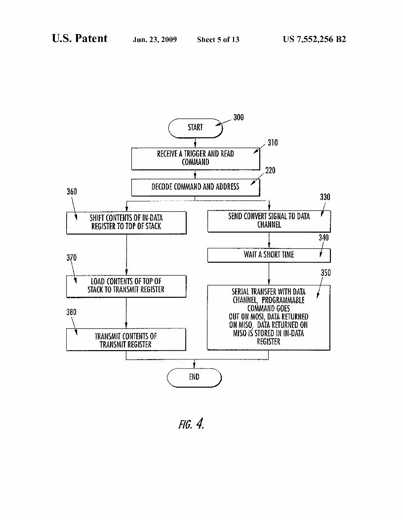
15 according to one embodiment of the present invention.FIG. 4 is a block diagram of the operations performed by
the NDI to retrieve data from a remote devices and illustratesthe ability of the NDI device to perform multiple tasks at the
20 same time while simultaneously communicating with the buscontroller according to one embodiment of the present inven-tion.
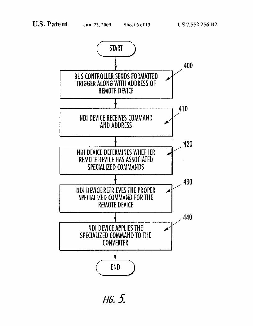
FIG. 5 is a block diagram of the operations performed totranslate commands sent by a controller to a remote device
25 into specialized commands used by a converter connected tothe NDI, such that the controller may communicate with theremote device according to one embodiment of the presentinvention.
FIG. 6 is a block diagram of the operations performed toso determine whether a controller is operating in either a syn-
chronous or asynchronous mode according to one embodi-ment of the present invention.
FIG. 7 is a block diagram of the operations performed to35 determine the bit rate at which a controller is transmitting
commands and data according to one embodiment of thepresent invention.
FIG. 8 is a block diagram of the operations performed by anNDI while the bus controller is assigning logical addresses
40 and group addresses to the network device according to oneembodiment of the present invention.
FIG. 9 is graphic diagram illustrating the synchronizationof an internal free running clock provided by the NDI device
45 to a data channel in order to synchronize the free runningclocks of multiple data channels attached to the networkthrough multiple NDI devices according to one embodimentof the present invention.
FIG. 10 is a schematic diagram of an electrical network50 system according to one embodiment of the present invention
implemented in an aircraft.FIG. 11A is a block diagram of the connection of the NDI
device of the present invention to a successive approximation
55 A/D that uses a convert signal from the NDI device to acquiredata with precise timing, according to one embodiment of thepresent invention.
FIG. 11B is a block diagram of the connection of the NDIdevice of the present invention to a digital filter and decimator
60 and a sigma/delta A/D that uses the synchronized dividedclock and possibly the synchronize signal to acquire data withprecise timing, according to one embodiment of the presentinvention.
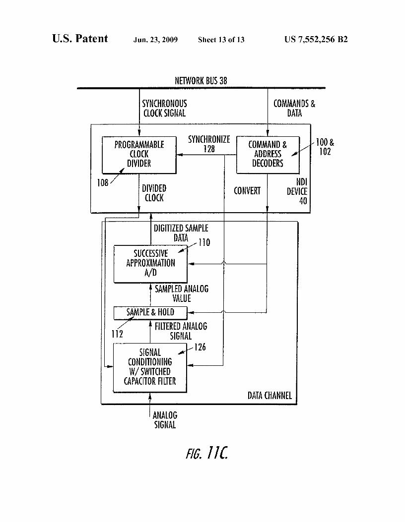
FIG. 11C is a block diagram of the connection of the NDI65 device of the present invention to a successive approximation
A/D and signal conditioning with switched capacitor filters,where the switched capacitor filters require both the convert

US 7,552,256 B29
10and divided clock signals to acquire data with precise timing, network devices that are connected to the controller by aaccording to one embodiment of the present invention. common network. FIG.1 is an illustration of one embodiment
of the implementation of the interface of the present inven-DETAILED DESCRIPTION OF THE INVENTION
tion. This illustration is provided so that a more complete
5 understanding of the present invention may be appreciated. ItThe present invention now will be described more fully must be understood that the present invention is not limited to
hereinafter with reference to the accompanying drawings, in this configuration and may be embodied in many differentwhich preferred embodiments of the invention are shown. network systems. The current embodiment of the NDI usesThis invention may, however, be embodied in many different the RHAMIS-HS protocol, however, other embodimentsforms and should not be construed as limited to the embodi- io contemplated by this disclosure may use other protocols.ments set forth herein; rather, these embodiments are pro- With regard to FIG. 1, a general embodiment of a net-vided so that this disclosure will be thorough and complete, worked system 30 in which the present invention is used isand will fully convey the scope of the invention to those shown. Specifically, the networked system includes a masterskilled in the art. Like numbers refer to like elements through- controller 32 such as high-level processor or personal com-out. 15 puter that processes data from and sends commands and data
As described above, many conventional data acquisition to data channels 34, such as sensors, actuators, and sub-and control systems use individual wiring to connect remote systems, located at desired points in the network. Importantly,devices, such as sensors, actuators, and subsystems, to a the networked system further includes a network controllercentral controller for data acquisition and control. Due to the 36 connected between the master controller 32 and a networklarge number of remote devices, the total of the individual 20 bus 38, and either one or several NDI devices 40 connectedwiring for each of these devices can be expensive, bulky, between the network bus and the data channels . Connectingheavy, and difficult to install and maintain. Further, since the network controller and NDI devices to the network bus aremany of these remote devices are analog, signals to and from respective transmitters, 42-46, and receivers 48 -52. A firstthe remote devices are susceptible to noise and signal degra- transmitter 42 connected between the network controller anddation. 25 the network bus transmits commands and data on the net-
As described in greater detail below, the present invention work, while a second transmitter 44 also connected betweenremedies these and other problems by providing a network
the network controller and network bus may be used in some
device interface (NDI) for connecting various data channels, embodiments to transmit a synchronous clock signal.that can be sensors, actuators, and subsystems, to a common In normal operation, the remote devices that are sensors arecontroller for transmission of commands and data to and from so connected to a specific object under study and sense charac-the data channels and the controller. Importantly, the NDI
teristics of the object such as temperature, strain, flex, speed,
device of the present invention connects various remote air flow, etc. Further, the remote devices that are actuators aredevices to the controller via a common network, thereby connected to mechanical members and other structures topermitting the various remote devices to share the same wir- operate on the object under test. One or several of the remoteing for communicating with the controller. Further, the NDI 35 devices are connected to a single NDI device of the presentof the present invention can interface to different types of data invention via individual data channels containing converterschannels, which can be analog-to-digital or digital-to-analog and signal conditioning devices. Further, either the masteror other. Sensors are connected to the NDI as analog-to- controller or the network controller may be configured to senddigital data channels and actuators are connected to the NDI
data and commands acro s s the network to the various network
as digital-to-analog data channels. The NDI of the present 4o devices. Given that both of these controllers are capable ofinvention is capable of taking the digital data from an analog- such action, the generic term bus controller is used in theto-digital channel, formatting it according to the proper pro- discussion below to describe operations that may be per-tocol, and transmitting it onto the network according to the formed by either the master or network controller.protocol. The NDI of the present invention is also capable of
With reference to FIG. 2, to acquire data from a sensor or
taking digital data from the network, providing it as digital 45 activate and actuator, the controller sends commands and datadata to a Digital-to-Analog converter (D/A), and causing the digitally across the network to the remote devices, where theD/A to convert the data to an analog signal. It is possible for command and data is designated for either one or a group ofother embodiments of the NDI to accept or produce analog the data channels on the remote devices. (See step 200). Thesignals directly to and from its data channels. By transmitting commands and data are transmitted across the network usingthe data across the network in a digital format, the commands 5o a data protocol. The NDI devices of the present inventionand data are less susceptible to noise and degradation. receive and interpret the data and commands using the struc-
Further, the NDI of the present invention operates in con- ture of the data protocol. (See step 210). Further, the NDIjunction with a data protocol that allows the controller to devices of the present invention determine whether the com-communicate with either one or several network devices at a mands and data are designated for the data channels con-time across the network. Importantly, the data protocol used 55 nected thereto. (See step 220). If so, the NDI either acquiresby the NDI device of the present invention has a fixed, low- data from the designated data channel if it is a sensor orlevel instruction set. Due to the simplicity of the protocol, the commands the data channel to perform a conversion if it is anNDI device of the present invention is not required to be a actuator. (See step 230). Analog data retrieved from the sen-high-level processor. Instead, in one preferred embodiment, sor channels is first converted into digital data, (see step 240),the NDI device of the present invention is a state machine 6o and then converted into the proper format according to theimplemented as an Application Specific Integrated Circuit
data protocol. Further, the digital data is transmitted to the
(ASIC). An advantage of using a state machine to implement controller. (See step 250).the NDI instead of a micro-controller or processor is that
As illustrated in FIGS. 1 and 2, the NDI device of the
many processes can occur simultaneously, which aids the present invention operates as an interface between the busNDI to be time deterministic and fast. 65 controller and the data channels. Importantly, the NDI device
As mentioned above, the NDI of the present invention is of the present invention is capable of accepting digitized,used as an interface between a common controller and various analog data signals from data channels for transmission

US 7,552,256 B211
12across the network bus. The NDI can also accept digital data generalized block diagram of a NDI device 40 according tofrom the bus controller and present it to a data channel. Then one embodiment of the present invention. As illustrated, thea D/A converter can change the data to an analog signal. It is
NDI device of the present invention is connected between the
possible that some data channels would accept and use the network bus 38 and remote devices 34 and 36, such as illus-digital data directly without converting it to analog. Some 5 trated previously in FIG. 1. In this embodiment, one of theembodiments of an NDI may have an analog-to-digital (A/D)
remote devices 34 is a sensor and the other remote device 36
converter and a D/A converter integrated into the NDI, is an actuator or similar device. Both remote devices containthereby being configured to accept or present analog signals signal conditioning devices, 58 and 60, for conditioning ana-from or to data channels. The NDI device of the present
log signals. With regard to remote device 34 the signal con-
invention also operates in conjunction with a selected data io ditioning 58 is for a sensor signal. The signal conditioning forprotocol to properly receive and decode or format and send
an actuator is shown in 60. Signal conditioning can include
data efficiently via a network bus. but is not limited to amplifiers, filters, attenuators, etc.Further, the NDI device of the present invention provides
Importantly, connected between the remote devices and the
additional operations and features, such as programmable
NDI device of the present invention are A/D and D/A con-trigger command conversion, and clock signals, that allow the 15 verters, 62 and 64, respectively. The A/D converter 62 iscontroller to communicate with different types of devices that connected between the NDI device and the sensor 34. Thecompose data channels. Additionally, the NDI device of the
A/D converter converts analog signals from the sensor chan-
present invention includes stored information and procedures nel into digital data for input into the NDI device. Similarly,for configuring the data channels connected thereto. A/D and
the D/A converter 64 is connected between the NDI device
D/A converters are examples of components of data channels 20 and the actuator device 36 and converts digital signals fromthat may need to be programmed or configured. The NDI
the NDI device into analog signals for input into the actuator
device of the present invention may also provide a local clock
channel. It is possible that some sensors and some actuatorssignal to data channels that is some fraction or multiple of the could produce or accept digital signals directly so that theA/Dlocal oscillator or synchronous bus clock. The local clock
62 or D/A 64 is not necessary.
signals of many or all NDI devices on a network can be 25 As illustrated previously in FIG. 1, the NDI device of thesynchronized by the bus controller. Further, theNDI device of
present invention is connected to the network bus via a first
the present invention operates in conjunction with the data receiver 50 that receives commands and data from the con-protocol to provide a unique logical address and group troller. A second receiver 52 is also provided for receiving theaddresses for each of the data channels, such that the data optional synchronous clock signal from the controller if thechannels may be either addressed individually, in a synchro- so network is operated in synchronous mode. A transmitter 46 isnized group, or all together. also connected between the NDI device of the present inven-
In addition to allowing for data communication between tion and the network bus for transmitting data to the control-the controller and remote devices and data channels having
ler. Further, a memory device 66 and a local oscillator 68 are
different configurations, the NDI device of the present inven- connected to the NDI device of the present invention. Differ-tion also allows for data communication across the bus net- 35 ent embodiments of the NDI device could integrate some orwork using different data transmission modes. Specifically, in all of the following: the receivers, transmitters, local oscilla-one mode of the present invention, the NDI device of the tor, and memory.present invention operates in conjunction with the controller
FIG. 3B provides an illustration of the various control logic
in a synchronous mode, in which a synchronous clock signal
components of the NDI device 40 according to one embodi-provided by the controller is used by the NDI device to 40 ment of the present invention. Specifically, the NDI device ofreceive commands and data from the bus controller. This this embodiment of the present invention includes ports, 70same synchronous clock signal is used by the NDI to send
and 72, for connecting to the data channels, 34 and 36. These
data to the bus controller or other network devices. ports are typically serial ports, but may be parallel ports inAs a note, the NDI devices typically do not transmit the some embodiments. The ports of the NDI device are con-
synchronous bus clock signal back to the bus controller. 45 trolled by individual port controllers, 74 and 76. Data linesInstead, the NDI devices typically only clock data out on
incorporated in each port include a data output line 78
received edges of the synchronous bus clock signal in the referred to as Serial MOSI (master out slave in), a chip enablesynchronous mode. Generally, only the bus controller trans- or chip select line 80 referred to as CE, a clock signal line 82mits the synchronous bus clock signal. Further, the bus con- referred to as Serial CLK, and a trigger 84. As illustrated, thetroller will typically include an asynchronous receiver for 5o data output line 78 consists of a configuration data output linereceiving data from the NDI devices. 78a and a data out/special command out line 78b. The con-
In another mode, which can be the same or different
figuration data output line 78a is used as described later forembodiment, the NDI device operates in conjunction with the configuring the data channel at power up. Further, the datacontroller in an asynchronous mode. In this embodiment, the out/special command out line supplies data from the busNDI device of the present invention analyzes and determines 55 controller to the data channel. The output select line 79the bit rate at which the controller is transmitting data on the toggles a select switch 86 between the configuration datanetwork bus and then uses this bit rate to retrieve commands output line and Serial out data line depending on whether theand data from the bus controller and send data to the bus
NDI device is in power up mode or in normal operation.
controller or other network devices. Also in the asynchronous
As mentioned, the NDI device of the present inventionmode, the NDI device may still synchronize data conversion 60 further includes a data stack 88 defined as a plurality of dataon data channels located on different NDI devices. Data con- registers creating a memory. The data stack is used for storingversion is synchronized on the separate data channels by
digital data acquired from a data channel. A data stack can
having it occur on or very shortly after the changing edge of
also be used for storing data from the bus controller to send toa special bit in a command from the bus controller. a data channel. The data stack is typically operated as a
These and other advantages are realized by the NDI device 65 last-in-first-out (LIFO) device, where the last value placed inof the present invention; one embodiment of which is illus- the data stack is the first value retrieved from the stack. Thistrated in FIGS. 3A and 3B. Specifically, FIG. 3A illustrates a way, no matter what the stack size, data will be returned to the

US 7,552,256 B213
14bus controller by different NDI devices in the same order. nels. There may be other uses for this memory data at powerThere is minimum delay between putting a new data value on up. This memory can also be used by the bus controller tothe top of the stack to when the bus controller can read it. store user-defined information such as network device instal-However, there would be a large delay if the bus controller
lation location, calibration data, etc. The contents of this
had to read data from the bottom of a stack. 5 memory are commonly called TEDs which stands for Trans-As illustrated, associated with the data stack is a stack
ducer Electronic Data Sheet.
depth register 90. The stack depth register indicates the num- Further, the NDI device of the present invention mayber of valid data words in the stack at that time. include control logic 106 for receiving commands and per-
Further, internal to the current embodiment of the NDI
forming built in testing, calibration, and transitioning the NDIdevice of the present invention are a status register 92 and a io device between a sleep and wake mode.data select multiplexer 94 for each data channel. Importantly, As illustrated in FIG. 1, the NDI device of the presentthe status register includes information relating to the status
invention communicates with a controller across a network
of the data channel, such as whether the data channel is in a
bus. The discussion of the various operations of the presentready mode, whether the data channel supports a command, invention described below are with regard to the NDI device.or whether there is a message transmission error, etc. The data 15 Detailed operation of the master and network controllers isselect multiplexer, depending on the data requested, connects not described herein. However, a complete detailed disclo-either the status register, data stack, or stack depth register, to sure of the operation of the master controller and networkan output data multiplexer 96. The data select multiplexer 94
controller is provided in U.S. Provisional Patent Application
for each channel is controlled by the respective port control- No. 60/254,137 entitled: NETWORK CONTROLLER FORler, 74 and 76. The output data multiplexer 96, in turn, selects 20 DIGITALLY CONTROLLING REMOTE DEVICES VIA Abetween the output of the two remote devices or a device
COMMON BUS and filed on Dec. 8, 2000. The contents of
inventory register 98. Different embodiments of the NDI
this patent application are incorporated in its entirety hereindevice may have different multiplexer arrangements in the
by reference.
NDI device, but the effect will always be to allow the bus
As mentioned, the NDI device of the present inventioncontroller to access any register for any data channel in an 25 provides several advantages. One important aspect of the NDINDI device that it needs. device of the present invention is self-configuration at power
The Device Inventory block 98 is used by the NDI device to up of the A/D and D/A converters and the remote devicesexecute the Device Inventory operations that are shown in the connected to the NDI device. As illustrated in FIG. 1, theflow chart in FIG. 8. remote devices connected to the network bus may be numer-
Further, the NDI device of the present invention also 30 ous and spread far apart making it difficult to configure theincludes an address decoder 100 and a command decoder
devices from a central location. In light of this, in one embodi-
102. As described later below, these decoders receive the ment of the present invention, the NDI device includes datacommand and data transmitted by the controller, decode the related to the gain, offset, filters, etc. of the signal condition-commands and data, and determine whether the commands
ing devices, 58 and 60, and data related to the A/D and D/A
and data are addressed to one or more of the data channels 35 converters stored in the memory device 66, (illustrated inconnected to the NDI device. If the commands and data are
FIG. 3A). Specifically, in one embodiment, the NDI device of
addressed for one of the data channels, the NDI device of the the present invention allows 16, 16-bit digital words from thepresent invention will operate on the data channel in accor- memory device to be output each of the ports, 70 and 72, atdance with the command. The above components are some- power up. This aspect of the NDI device of the present inven-times referred to herein as a device interface. 40 tion allows for automatic configuration of off-the-shelf A/D
An NDI device will include a non-volatile memory indi- and D/A converters.cated in FIG. 3A as memory device 66 that will be used by the
The configuration data stored in the memory device is
NDI to store the UUID, protocol version, number of data programmable by the controller. The 16, 16-bit words can bechannels, logical addresses, group masks, configuration data, programmed to be split into 32, 8-bit bytes for output by theand other data that the manufacturer or user may define. The 45 ports to the A/D and D/A converters and signal conditioning.communication with this memory device is illustrated in FIG. Further, the NDI device of the present invention can be pro-3B by the input and output lines from the configuration reg- grammed by the controller to change the Serial clock 82 phaseister 104 to the memory device. The bus controller will be able and Serial clock 82 polarity at which the configuration data isto read the memory and write to various memory locations output at the ports, 70 and 72.according to the protocol. The logical address and group 50 In addition to configuring the A/D and D/A converters andmask fields in memory are special. They can only be written signal conditioning devices atpowerup, the NDI device of theto by the bus controller immediately after the NDI device has present invention is also configurable to operate with differ-won a Device Inventory Competition according to the flow ent types of A/D and D/A converters and signal conditioningdiagram in FIG. 8. This allows every NDI device to be
devices. Specifically, there are many types of converters, such
uniquely identified by the bus controller and then the logical 55 as successive approximation A/D converters and sigma/deltaaddresses and group masks to be assigned. By mandating that oversampling converters. These converters may operate dif-a Device Inventory Competition must be won prior to writing
ferently in terms of clocking and operational delay. Further,
to these fields, it becomes virtually impossible to accidentally some signal conditioning devices, such as switched capacitorchange these values. This same sort of memory protection can
filters and digital anti-alias filters operate differently in terms
be applied by the NDI device manufacturer to other memory 60 of clocking.fields. For example, as illustrated in FIG. 1, in the synchronous
At power up some of the contents of the non-volatile mode, the controller provides a synchronous clock signalmemory 66 are loaded into the logical and group address across the network bus to the network devices. In the syn-decoder registers 100, configuration registers 104 for the chronous mode, the synchronous clock signal is used as theSerial ports, 70 and 72, command translation registers in port 65 clock signal for transmitting network data. Some A/D con-controllers, 74 and 76, and some contents are sent out the verters, such as Analog Devices' AD7714 converter need aSerial ports or other parallel ports for configuring data chan- continuous clock signal to operate correctly. This clock is

US 7,552,256 B215
16usually lower frequency than the synchronous clock signal
filters, or sigma/delta converters, etc. This clock signal con-
provided by the controller. In light of this, in one embodiment
tinues running even when operational steps 300-380 are notof the present invention, the NDI device of the present inven- taking place.tion may include a clock divider 108. The clock divider may
In instances where the Universal Asynchronous Receiver
either be connected to the synchronous clock signal output by 5 Transmitter (DART) protocol is used, the controller transmitsthe controller as shown in FIG. 3B or it may be connected to a command comprising a start bit, a command field, ana local oscillator 68, as illustrated in FIG. 3A. address filed having an unused last bit set to 0, and a stop bit
This clock signal provided by the NDI device can be syn- set 1. In this embodiment, the NDI device of the presentchronized by the bus controller as shown in FIG. 9. The clock
invention commences performance of the function at each
signal can simultaneously be synchronized in one, several, or io data channel coincident with the transition from the unusedall NDI devices on the bus. In the example in FIG. 9 the
bit of the address field to the stop bit.
internal clock frequency is shown as 1/4 the synchronous bus
In addition to clock and delay issues, some A/D and D/Aclock frequency. It could actually be any other fraction of the converters also require special commands. For example,synchronous bus clock frequency. some A/D and D/A converters are programmable to take
FIG. 4 is a block diagram of the operations performed by 15 different readings from a sensor. For instance, in one appli-the NDI in response to one particular command from the bus cation, an A/D converter is connected to a strain gauge thatcontroller. This diagram illustrates that the NDI device is senses strain in three dimensions. Each readable dimension iscapable of doing more than one task at a time. The ability of
addressable with a separate 16-bit address. Either one or all of
the NDI device to do multiple tasks at the same time allows the measurements for each dimension may be accessed bythe NDI device of the present invention to acquire or control 20 applying the associated 16-bit command to the converter. It1 or more data channels at the same time while simulta- may become burdensome to store all of the bit commands inneously communicating with the bus controller. the controller and transmit them across the network bus. To
With reference to FIG. 4, in operation, the NDI device of
simplify operation of the protocol, (as discussed below), thethe present invention initially receives a command, (see step
NDI of the present invention maintains these special com-
310), such as Trigger and Read command, from the controller 25 mands so that they do not have to be kept up with by theand interprets the command. If the command and address are controller or sent across the network. In light of this, in oneintended for a data channel on the NDI device the NDI device embodiment, the NDI of the present invention includes thebegins the operations shown in steps 330 and 360 in parallel. specialized bit commands associated with the A/D or D/ASpecifically, the NDI device sends a convert signal to the data converters connected to the NDI. With reference to FIGS. 3Achannel attached to the NDI. (See step 330). The rising edge so and 313, these commands are originally stored in the memoryof this data pulse occurs at the center edge of the parity bit at
device 66, where they are programmable. During power up,
the end of the Trigger and Read command. The convert signal
these specialized bit commands may be stored in the com-is provided to latch analog data into the sample and hold
mand decoder 102.
circuitry of an A/D converter, or can be used to cause a D/A to
With reference to FIG. 5, in operation, when a remotestart a conversion process. The precise timing of the rising 35 device having a converter with specialized commands is to beedge of this signal allows many data channels to know when addressed, (to either obtain data from a sensor or in the case ofto sample or convert analog data, even if the network devices an actuator, activate the remote device), the controller willare not operating in synchronous mode. send a properly formatted trigger command along with the
After the convert signal is created, a short pause occurs. address of the data channel with the converter. (See step 400).(See step 340). This pause allows the data channel to have 40 (The format of commands is discussed below). When the NDItime to convert the analog signal latched in its sample and
associated with the data channel receives the command and
hold to be converted into a digital value. In the present address, (see step 410) the NDI initially determines whetherembodiment of the NDI device, this pause is programmable. the remote device addressed needs specialized commands.There are two choices. It can be only a few hundred nanosec- This is done by comparing the address received to the addressonds long, or it can be programmed to be 6 microseconds 45 associated with the data stored in the command decoder. (Seelong. step 420). Based on the address, the NDI of the present
After the pause, a serial transfer occurs. (See step 350). invention retrieves the proper specialized command from theDuring this Serial transfer a programmable word is clocked
command translation register. (See step 430). The specialized
out on the MOSI line. This programmable word is used to command is then applied to the converter to either receivecause special A/D converters to output data. An example is an 50 information, in the case of a sensor, or activate an actuatorAD7714. As this serial transfer continues, data is returned
corresponding to the command. (See step 440).
from the data channel to the NDI device. The digital data
As briefly discussed, the controller and the NDI device ofreturned to the NDI device on the MISO line is stored in the the present invention are capable of operating in either ain data register 89. synchronous or asynchronous mode. In the synchronous
At the same time operational steps 330, 340, and 350 are 55 mode, the controller provides a continuous synchronousoccurring, operational steps 360, 370, and 380 are also occur- clock signal. The synchronous clock signal is used by the NDIring. In operation step 360, the contents of the in data register
device of the present invention to clock in data from the bus
89 are shifted into the top of the data stack. Next, the contents controller and to clock data out to the controller. This allowsin the top of the data stack are loaded into the transmitter the bus controller to pick any data rate between 0 bits/sec upregister. (See step 370). The last operation is for the contents 60 to some maximum bit rate.of the transmitter register are transmitted back to the bus
The NDI device of the present invention can automatically
controller by the NDI device's transmitter 46. (See step 380). detect whether the controller is operating in the synchronousDuring all of these operations, the NDI interface is provid- or asynchronous mode. Specifically, with reference to FIGS.
ing a continuous clock signal to the data channel. Not all data
3A, 313, and 6, the NDI device of the present invention con-channels will use this clock but it is available. The frequency 65 tinuously checks the signal received on the second receiver 52of this clock is programmable. This clock signal is useful for using a clock detector. (See step 500). If a synchronous clockrunning devices such as switched capacitor filters, digital
signal is present, (see step 510), the NDI device of the present

US 7,552,256 B217
18invention operates in the synchronous mode, (see step 520), systems and operating in both synchronous and asynchronousand uses the synchronous clock signal from the controller to mode, the NDI device of the present invention can also saveclock data in and clock data out. However, if the NDI device overhead in the transmission of data across the network.of the present invention does not detect a synchronous clock
Specifically, as illustrated in FIG. 313, the NDI device of the
signal from the second receiver 52, (see step 510), the NDI 5 present invention includes a data stack 88. In the case wheredevice of the present invention operates in asynchronous the NDI device is connected to a sensor remote device, themode. (See step 530). data stack is an In Data Stack. The In Data Stack contains data
As mentioned above, in asynchronous mode, the controller received from the data channel. In this instance, the datamay operate at various bit rates. In light of this, in one stored in the In Data Stack can be read out by the controllerembodiment, the NDI device of the present invention detects io either one word at a time, (i.e., one register at a time), or as athe bit rate at which the controller is operating. Specifically, block of data, (i.e., multiple registers at a time). Reading awith reference to FIG. 7, in this embodiment, after the NDI
block of data from the data stack at a time saves network
device of the present invention determines that the controller overhead.is operating in asynchronous mode, the NDI device of the
Further, in instances in which the NDI device of the present
present invention monitors the bits of the command and data 15 invention is connected to an actuator remote device, the datatransmitted by the controller. (See step 600). The NDI device stack is an Out Data Stack. In this case, the Out Data Stackdetermines the time betweenreceipt of each bit using a bit rate contains data transmitted by the controller to be output to thedetector. After a predetermined number of bits have been actuator data channel . When a trigger command is sent to thereceived having substantially the same time between trans- actuator, the actuator performs a digital to analog conversionmissions, (see step 610), the NDI device of the present inven- 20 of the word at the top of the data stack, then NDI device willtion chooses and operates at the bit rate of the data being sent pop the stack, and transmit the new word at the top of the stackto the NDI device. (See step 620). Importantly, the ability of
to the D/A. Data words can be written to the Out Data Stack
the NDI device to detect bit rate is advantageous for fast
individually by the controller or as a block of words. Writingrecovery when there are power glitches in the networked
a block of data to the Out Data Stack instead of one a time
system, or where the controller has transitioned from syn- 25 saves network overhead.chronous to asynchronous mode. A second important advan- In addition to the advantages described above, the NDItage of the automatic synchronous clock detect and automatic
device of the present invention also provides additional
bit rate detect features is that it allows a single type of NDI
advantages. Specifically, in one embodiment, the NDI devicedevice to communicate on the network using different modes of the present invention operates in conjunction with a pro-of network communication. Designer of the network system 30 tocol that allows data channels to communicate over a simplecan choose the mode of network communication that is opti- and high-speed, yet robust, digital multi-drop network. Itmized for the particular application of the network system. must be understood that any applicable protocol could be
In one further embodiment, the bus controller can com- used in conjunction with the NDI device of the present inven-mand the NDI device to receive and transmit data at a specific tion. However, described below is a particular protocol thatbit rate. The bus controller sends a change bit rate command 35 provides several advantages when used in the networked sys-followed by the bit rate the NDI devices is to change to. After tem 30 illustrated in FIG. 1. One important advantage beingthat the NDI device will receive data from and transmit data to that the simplicity of the protocol allows the NDI device to bethe bus controller at the bit rate instructed by the bus control- implemented as a state machine, as opposed to a high-leveller. Further, the controller may send an example message at processor.the new bit rate, and the NDI of the present invention will 40 Specifically, the protocol is designed to insure low-levelchange to the new bit rate before real commands and data are communication control interface, (i.e., network controllerssent. and NDI devices). The protocol makes possible the develop-
Another advantage of the NDI device of the present is the ment of controller and network device interfaces that areability of many data channels on many different NDI devices
highly miniaturized within the network. If the network con-
on a network bus to sample or convert analog data at substan- 45 troller and NDI devices are implemented in an Applicationtially the same time when communicating to the bus control- Specific Integrated Circuit (ASIC) or FPGA working in con-ler in the synchronous or asynchronous modes. One method
junction with the protocol, the network controller and NDI
of synchronization of data sampling or conversion in the
device can respond quickly and efficiently allowing for maxi-asynchronous mode is accomplished by having the rising mized bus efficiency. If the bus controller or NDI device isedge of convert signal 84, (see FIG. 313), go high at or very 50 implemented as an ASIC, the bus controller and NDI devicesshortly after the changing center edge of the convert com- can be made very small.mand from the bus controller. Some protocols call a convert
The protocol of the present invention also has a low-over-
command a trigger command. The ability of the protocol and
head command structure. The protocol of the present inven-NDI devices to take data or convert data simultaneously even tion does not use a fixed-length message. The length of thein the asynchronous communication mode is called isochro- 55 message varies depending on the command. This, in turn,nous. permits the elimination of unnecessary data being transmitted
The second method of synchronization data sampling is by
if it is not needed to execute a command. In addition, theproviding synchronized clock signals from each NDI device command set is minimal and straightforward thus allowingto each data channel associated with each NDI device. The the user to easily pass data through the network bus withclock signals are synchronized by the bus controller using the 60 minimal manipulation.synchronize command, and the NDI devices synchronize in
As discussed, the NDI device of the present invention
response to the command according to the timing in FIG. 9. operates in conjunction with a protocol that has a fixed, low-That way all data channels using a clock signal that has a
level instruction set that, in turn, allows in some case for use
frequency that is a divided fraction of the synchronous bus of simplified controllers and network device interfaces onclock will all be running nearly perfectly synchronously. 65 network devices. Specifically, the low level command set
In addition to providing an interface with different types of
allows the NDI devices to be implemented as state machinesA/D and D/A converters and different signal conditioning
instead of processors or micro-controllers. An example of

US 7,552,256 B219
20how the low level command set works is given here. If the bus ter coding is MIL-STD-1553. Specifically, each bit of the datacontroller wants to read a data word from the memory of an
is detectable by one detectable transition, (i.e., "0" is defined
NDI device it sends a command to the NDI called set pointer, as low to high and "1" is defined as high to low). Further, eachthen follows the command with the pointer value. The NDI
message consists of a sync pattern, a message body, and a
decodes the command and sets its memory address pointer to 5 parity flag. The BiSenSys transmission protocol can be oper-be the value sent by the bus controller. The memory address ated in synchronous or asynchronous mode and the can bepointer only needs to be a register that latches the value sent
implemented to operate at any data rate from 1 Hz-10 MHz in
by the bus controller. Next, the bus controller will issue the the synchronous mode or at 1.25, 2.5, 5.0, and 10.0 megabitsread memory word command to the NDI device. The NDI
per second in asynchronous mode. Additionally, the protocol
device responds by accessing the memory word pointed to by io of the present invention may be implemented in a UARTits memory address pointer, and transmitting it to the bus
based protocol. This protocol is designed to operate at a 1.0
controller. If the bus controller wants to read a block of data megabit per second data rate and uses a 9-bit message formatfrom the memory of the NDI it repeats the process multiple and non-return-to-zero bit coding.times. There are at least three types of data frames transmitted
If the command set is a high level command set, the above 15 across the network bus, with the data frames differingdescribed read process, would be implemented as a read
between the BiSenSys protocol and the UART protocol.
special memory block command. The NDI device would need
There are 3 types of BiSenSys data frames. The first type is ato be able know where to set its pointer to access the special
command frame. A command frame consists of a command
memory block, set its pointer, know how big the special
sync pattern followed by 10 Manchester encoded addressmemory block is, and then send the special memory block. 20 bits, followed by 7 Manchester encoded command op-codeThis protocol offloads many of these tasks, such as keeping
bits, and 1 Manchester encoded parity bit. The command sync
track of where special memory information is stored, and how consists of the one and a half bus bit periods high and one andbig the block sizes of the special memory information is, and
a half bit periods low state on the bus.
where to store special memory data, from the NDI device. The second type of frame is an argument frame. An argu-These tasks are performed by the bus controller instead by 25 ment frame begins with a data sync pattern which is followedstringing low level instructions like set memory pointer and
by 16 Manchester encoded argument bits, one Manchester
read and write memory together. encoded flag bit, and finally one Manchester encoded parityAs discussed, the NDI device of the present invention
bit. The data sync pattern consists of the one and a half bit
operates in conjunction with a protocol that has a fixed, low- periods low followed by one and a half bit periods high. Thelevel, and low overhead instruction set that, in turn increases 30 last type of BiSenSys frame is the data frame. Data framesthe actual data rate on the network bus when used with smart
begin with the data sync pattern, which is followed by 16 bits
sensors and actuator. Network traffic for networking sensors of Manchester encoded data, one Manchester encoded flat bit,and actuators is different from regular computer network
and one Manchester encoded parity bit. The only difference
traffic. Computer networks need to transfer large data files or
between an argument frame and a data frame is that argumentmessages from one computer to another. Consequently they 35 frames are transmitted by the bus controller data frames arehave checksums and block sizes associated with the messages transmitted by network devices. Arguments are only trans-to ensure robust and error free data transmission. These mitted by the bus controller following certain commands. Thechecksums and block sizes, or other overhead, associated
commands that require an argument to follow them are
with these computer network protocols is not a problem
defined in the RHAMIS/BiSenSys protocol. If the bus clockbecause the size of the overhead is small compared to the total 40 is usedinthe BiSenSys synchronous mode, it is transmitted inmessage size. Network traffic for sensors and actuators is quadrature to the Manchester encoded bit stream.different because in many cases, most of the messages on the
In the case of the UART protocol, the message format
network are very small messages with only 16 bits of data. If
contains 3 or more 11-bit frames. Each message has threea block size, checksum, or other unnecessary overhead is required frames per message with two additional optionaladded to the small 16 bit data message, the checksums, block- 45 frames per message depending on the command issued. Thesize, and other overhead can contain more bits than the actual
first bit in every frame is a start bit (set to 0), and the final bit
16 bit data message. This effectively reduces the bandwidth
of all frames is a stop bit (set to 1). The first frame in a messageof the sensor and actuator network bus. The NDI devices of
is an address frame for the UART protocol. It is in the form of:
the present invention solve this problem by using a message a start bit, an 8-bit address field, an address bit set to 1, and aprotocol that does not add any unnecessary overhead such as 50 stop bit. The second frame in a UART message is a commandchecksum and block size to short 16 bit messages. The only
frame. A command frame consists of a start bit, a 7 bit com-
overhead added to these short 16 bit messages is a sync mand field, an unused bit, the address bit set to 0, and the stoppattern to indicate the start of a message, a flag bit, and a parity
bit. If argument frames belong in the UART message, they
bit. The parity bit is used to check for errors in the 16 bit
follow the command frame. They consist of a start bit fol-message. The flag bit indicates if an error condition exists in 55 lowed by 8 argument bits, an address bit set to 0, and the stopthe sending NDI device or associated data channel. bit. The last frame of a UART message is a checksum frame.
The protocol of the present invention is typically transmit- It consists of a start bit, 8 bit checksum, which is the moduloted in a Manchester encoded format, but may also be imple- 2 sum of the address, command, and data bits withno carry, anmented in a Universal Asynchronous Receiver Transmitter address bit set to 0, and a stop bit.(UART) format protocol, if needed, to communicate with 60 In addition to providing a protocol having a low-levelother UART systems. For example, in one embodiment, the
instruction set that operates in either synchronous or asyn-
protocol uses an RS-485 based, multi-drop, Manchester chronous mode and different transmission protocols, theencoded protocol referred to as Bi-Phase Sensor and System present invention also provides a method for assigning unique(BiSenSys). BiSenSys is an 18-bit high speed, highly efficient addresses to each data channel. As illustrated in FIG. 1, in aprotocol foruse in connecting remote devices and subsystems 65 typical networked system 30, there will be numerous datatogether on a digital bus structure that uses Manchester channels connected to a plurality of different NDI devices, allencoding. An example of another protocol that uses Manches- of which use a common network bus for communication with

US 7,552,256 B221
the bus controller. Further, each of the network devices mayhave several data channels or several tasks that can be com-manded by the NDI device. The protocol of the present inven-tion provides three types of addresses for each data channel ofa network device. Specifically, each data channel on each 5
network device can be assigned an individual logical address,a global address, and if configured, a group mask.
The logical address is an address recognized by a singledata channel on a network device or a single controllable taskwith a network device. A global address, on the other hand, is iorecognized by all of the data channels of all of all of thenetwork devices, while a group address is recognized by asubset of all of the data channels of all of the network devices.Data channels are not assigned group addresses. They areassigned group masks. Each bit in the group mask corre- 15
sponds to a group address. In this way a single 16-bit maskcanbe usedto assign a data channel to 16 groups. For exampleif the 1 st and Yd
bit of the group mask are set to 1, the datachannel recognizes itself as belonging to groups 1 and 3. Itwill respond to command messages having a group address of 20
either 1 or 3. These three different addresses are important asthey allow the controller to either communicate with an indi-vidual data channel of one network device or a group of datachannels, either in the same network device or in severalnetwork devices, or with all of the data channels of all net- 25
work devices. Each of these addresses is described in detailbelow.
The determination of the logical and group addresses maybe by any selected method. A preferred method is described inU.S. Provisional Patent Application No. 60/254,137 entitled: 30
NETWORK CONTROLLER FOR DIGITALLY CON-TROLLING REMOTE DEVICE VIA A COMMON BUSand filed on Dec. 8, 2000. This method uses the UniversalUnique Identifier (UUID) associated with each networkdevice. The UUID code is an 80-bit code that is unique to 35
every network device and is based on the location and date thedevice was manufactured.
With reference to FIG. 3A, the UUID for network device ofthe present invention are typically stored in the NDI device'smemory device 66. During the determination of the logical 40
and group addresses, the controller sends various commandsto the NDI devices of the present invention commanding themto access their respective memory device, analyze the indi-vidual bits of the UUID and either respond or remain silentbased on whether certain bits are 1 or 0. This allows the bus 45
controller to discover the UUID of every network device, onenetwork device at a time. Immediately after finding the UUIDof a network device, the bus controller will assign logicaladdresses and group masks to every data channel on thatnetwork device. 50
FIG. 8 is a flow chart of the steps taken by a network deviceusing an NDI device, under control of the bus controller, touniquely identify itself to the bus controller. To begin aDevice Inventory session NDI devices are enabled using theDevice Inventory Enable command. This puts the NDI in the 55
Device Inventory mode. (See step 700). If address "0" (thereserved global address for all devices) is specified in theaddress field, every network device on the bus will put itselfinto the Device Inventory mode. If a currently assigned logi-cal address is specified in the address field, that network 60
device will put itself into the Device Inventory mode. If acurrently assigned group address is specified in the addressfield, all network devices belonging to that group will putthemselves into the Device Inventory mode.
Various function codes in the Device Inventory command 65
are used during the UUID word search. The Device Inventorycommand with the New UUID Word Search function code
22sets all Device Inventory session enabled devices into theUUID Word Search mode. (See step 705). Network deviceson the bus will not compete in a UUID Word Search unlessthey are in the UUID Word Search mode. Immediately afterbeing commanded into the Word Search Mode, the NDIdevice automatically proceeds by loading the least significantbit of the UUID into a first register and a "1" into a secondregister. (See step 710). When NDI devices are in the UUIDWord Search Mode they will respond to the two UUID BitCompetition function codes.
The Master Controller will issue the Device Inventorycommand withthe UUID Bit Competition, No Dropout f mc-tion code. All NDI devices will make a decision based on thiscommand. (See step 720). The NDI device will proceed tostep 730 and make a decision bases on its bit in register 1. Ifthis bit is a "1," (see step 730), the network device will remainquiet. If this bit is a "0," the network device will transmit aUUID pulse. (See step 740). The network device will thenmove the evaluated bit (either a "1" or a "0") into bit register2, access its next UUID bit and load it into bit register 1. (Seestep 760).
The Master Controller will listen for UUID pulses trans-mitted on the bus. When the Master Controller hears a UUIDpulse it knows at least 1 network device has a "0" for itscurrent UUID bit. If the Master Controller hears at least oneUUID pulse, the next command it will issue is the DeviceInventory command with the UUID Bit Competition, 1'sDropout function code. The NDI device will have to interpretthe command and make a decision. (See step 720). When anetwork device hears this command and code, it will look atits UUID bit inregister 2. (See step 780). If this bit is a "1 ", thenetwork device will exit the current UUID Bit Competitionmode and quit competing in the UUID Word Search. If the bitin register 2 is a "0", the network device will look at the bit inregister 1. (See step 730). If it is a "0", the network device willtransmit a UUID pulse. (See step 740). If this bit is a "1", thenetwork device will remain quiet. The network device willthen move the bit in register 1 into bit register 2, access its nextUUID bit and load it into bit register 1. (See step 780).
If the Master Controller does not hear any UUID pulse onthe bus, the Master Controller will know that all networkdevices still in UUID Word Search mode have a "1" in bitregister 2. In response to this, the next command the MasterController will issue is the Device Inventory command withthe UUID Bit Competition, No Dropout function code. Whena network device receives this command it will remain in thecompetition without regard to what is in its registers. Inresponse to the command all devices in the competition willlook at bit register 1. (See step 730). If it is a "0", the networkdevice will transmit a UUID pulse. (See step 740). If it is a"1", the network device will remain quiet. The networkdevice will move the bit in register 1 into bit register 2, accessits next UUID bit and load it into bit register 1. (See step 760).
The UUID Bit Competition described in this section isrepeated for all 80 UUID bits. The Master Controller willhave to issue a combined total of 81 UUID Bit Competitionfunction codes. (See step 750). The Master Controller mustissue the 81'st UUID Bit Competition function code so thatthe last network devices on the bus can resolve who had thewinning last bit.
After the Device Inventory command with the UUID BitCompetition function codes has been issued for a combinedtotal of 81 times there will be only one network device left inUUID Word Search mode. This network device is the winner.(See step 770). This network device has now been uniquelyidentified to the bus controller and will respond with thecontents of a special memory location. (See step 780). The

US 7,552,256 B223
high byte of the special memory location will hold the pro-tocol revision number, and the low byte will be the number ofdata channels on the network device. The winning networkdevice and the bus controller will know the network devicehas won by winning all 81-bit competitions.
When the winning device has received the 81 st UUID bitcompetition function code, the device will respond with aBi-Phase compliant data field containing the protocol versionnumber and the number of channels the device has stored inits memory. (See step 780). The bus controller may use thisinformation to determine logical address channel assignmentin the winning device. The winning network device willunprotect its logical address and group mask memory loca-tions. (See step 790). The bus controller will assign logicaladdresses and group masks immediately following. (See step800). If the data channel includes a plurality of the channels,the Master Controller will assign logical addresses and groupmasks to each channel. (See step 810). After the logicaladdresses and group masks have been assigned, the networkdevice will exit the device inventory mode. The bus controllerwill repeat the UUID word searches until all network deviceshave been discovered, and a logical address and group maskassigned to every channel. The bus controller knows it hasdiscovered all devices when the UUID if discovers in the busis all 1's. No network device will ever have a UUID of all 1's.
As described above, each channel for each network deviceis provided with a logical address that uniquely identifies thedata channel. Further, there are group addresses that addressa number of data channels, and a global address that addressesall channels of all network devices. The global address is usedfor the exchange of global data and commands. The groupaddress is an address that is recognized by multiple datachannels of the network devices. Group addresses cause oneor more data channels to respond to the same command at thesame time. It is possible to have only one data channelassigned to a group address. Associated with the groupaddress is a group mask stored in the address decoder 100.The group mask is a 16-bit word, where each bit set to 1represents the groups that the data channel belongs.
As an example, in one embodiment, the global address isassigned 0000hex. In this embodiment, if the address0000hex is transmitted, all of the NDI devices will follow thecommand. This is typically used for resetting the system ortesting the system. Further, in one embodiment, the groupaddresses are selected in the range of 0001hex to 000fhex. Inthis embodiment, when an address in this range is receivedbya NDI device, it will compare the group address with thegroup mask stored in the address decoder register 100. If thebit in the group mask corresponding to the group address isset, the NDI device data channel of the present invention willinterpret and follow the command associated with the groupaddress. For example, if the group mask stored in the deviceinventory register is 1OOOOOOO11OObin, the NDI devicebelongs to group addresses 0001hex, O003hex, and OOO2hex.
The group address scheme is designed to permit the user toset up time deterministic triggers for groups of sensors oractuators at various sample rates. Table 1 illustrates a group ofsensors having different sample rates and their group assign-ments, and Table 2 the sequence for polling the devices. Ascan be seen from these tables, the data channels can begrouped together such that they may be triggered simulta-neously but at different sample rates.
24
TABLE 1
Sample Rate
5Logical Address Device (Samples/sec) Group Address
16 Temperature 1 125 117 Pressure 1 250 L218 Strain 1 500 L2,3319 Strain 2 500 L2,3320 Strain 3 500 L2,33
10 21 Strain 4 500 L2,3322 Accelerometer 1 1000 1, 2, 3, 423 Accelerometer 2 1000 1, 2, 3, 424 Accelerometer 3 1000 1, 2, 3, 425 Accelerometer 4 1000 1, 2, 3, 4
15
TABLE 2
Command Execution Time Action
20 0 Issue Trigger Command to Address 1Poll Addresses 16 through 25
1 msec Issue Trigger Command to Address 4Poll Addresses 22 through 25
1 msec Issue Trigger Command to Address 3Poll Addresses 18 through 25
251 msec Issue Trigger Command to Address 4
Poll Addresses 22 through 251 msec Issue Trigger Command to Address 2
Poll Addresses 17 through 251 msec Issue Trigger Command to Address 4
Poll Addresses 22 through 251 msec Issue Trigger Command to Address 3
30 Poll Addresses 18 through 251 msec Issue Trigger Command to Address 4
Poll Addresses 22 through 251 msec Restart Sequence
Service Commands60
00 No Op01 Built in Test02 Reset03 Read Status Register04 Device Inventory Enable
65 05 Device Inventory06 Control Pass
35 With regard to the group addresses, if the controller sendsout a group address, the address decoder 100 and a commanddecoder 102 of the present invention will decode the addressportion of the command and will compare the group addressto group mask stored in itself. If the group mask indicates that
40 the network device is subject to the group address, the properdata channel will perform the command associated with thegroup address on the network device.
Described above, the addressing methods used with the
45protocol allows the controller to send commands and data toeither one or several of the network devices, with the differentforms of data transmitted depending on whether BiSenSys orUART is used. Provided below are the commands typicallyused to communicate across the network bus. As stated pre-viously, the protocol of the present invention is designed to
So maximize efficiency so that the commands and response mes-sages can vary in length depending on the data quantityrequired to execute any command. In order to accomplishthis, the protocol of the present invention provides three levels
55 of utility. These commands are listed in Table 3.
TABLE 3
Command (hex) Command Description

US 7,552,256 B225
26
TABLE 3-continued
Command (hex) Command Description
07 Wake08 Sleep09 E-CalibrationOA Z-CalibrationOB SynchronizeOC Baud Select
OD-OF ReservedData Commands
20 Trigger21 Trigger and Read22 Read In-Data Register Word23 Read In-Data Stack Word24 Read In-Data Stack Block25 Query In-Data/Out-Data Stack Depth26 Write Out-Data Stack Word27 Write Out-Data Stack Word/Acquire to In-Data
Register28 Write Out-Data Stack Block
29-2F ReservedMemory Commands
30 Set Memory Pointer31 Read Memory Word with Current Pointer32 Read Memory Block with Current Pointer33 Write Memory Word with Current Pointer34 Write Memory Block with Current Pointer35 Read Memory Word with Passed Pointer36 Read Memory Block with Passed Pointer37 Write Memory Word with Passed Pointer38 Write Memory Block with Passed Pointer
39-71' Reserved
One level of commands is the service commands. Servicecommands are intended for network housekeeping, networkdevice interface status, power control, calibration, and busmaster arbitration. These commands are briefly describedbelow. For example, the No Op command instructs the NDIdevice of the present invention to take no action. The No Opcommand is typically used in initialization of operation or bythe master or network controller, (see FIG. 1), to maintain buscontrol.
The Built-In-Test (BIT), E-Calibration, and Z-Calibrationcommands are used to perform self-test on the NDI devicesconnected to the network bus. For example, the BIT com-mand commands the NDI device to perform a check of inter-nal circuitry. The E-Calibration command forces an excita-tion calibration, where the input from a sensor network deviceis replaced with a reference voltage, and the NDI device takesa reading to determine the calibration of the NDI device at thereference voltage. Similarly, the Z-Calibration command ini-tiates a zero calibration measurement, where the input for asensor data channel is shorted. The NDI device takes a read-ing to determine the offset of the data channel.
The protocol also includes two types of reset commands,namely Reset and Synchronize. The Reset command initial-izes all the network device interfaces of the present inventionthat are connected to the networkbus to a power-up state. ThisReset command is typically used by the controller to reset thebus and network devices when necessary and regain controlof the network bus.
The Synchronize command is an important command forestablishing and maintaining synchronization between sev-eral NDI devices. Specifically, as discussed previously, someA/D and D/A converters require a continuous clock signalthat is different from the synchronous clock signal providedby the controller. This clock signal is provided by a dividerthat divides down either the synchronous bus clock signal or
the clock signal from a local oscillator. This divided clocksignal is used by the converter to convert data. Although thedivider provides the proper clock frequency needed by theconverter, the presence of these different dividers on the dif-
5 ferent NDI devices can cause the converter on one NDI deviceto not be synchronized with a converter on another NDIdevice. Specifically, all of the converters may be operating atthe same frequency, but the dividers may be out of phase.
In light of this, the Synchronize command synchronizes the10 divided clock signal among a plurality of NDI devices. Spe-
cifically, with reference to FIG. 9, when the divider is usingthe synchronous clock signal and the Synchronize commandis issued, the NDI device will control its clock divider to resetand restart producing the clock signal. All of the NDI devices
15 will do the same reset and restart of their clock dividers at thesame time according to the group or global address used in thesynchronize command.
FIGS. lla, llb, and llc illustrate alternative embodimentsof how the NDI device of the present invention can be
20 attached to and control different data channels. Some datachannels will only need the convert signal from the NDIdevice to acquire data with precise timing as in FIG. 11A.Some data channels will need only the synchronized dividedclock and possibly the synchronize signal to acquire data with
25 precise timing in FIG. 11B. Some data channels, such as inFIG. 11C may require both the convert and divided clocksignals to acquire data with precise timing.
With reference to FIGS. 11A-11C, the use of the Synchro-nize command is illustrated with respect to causing switched
30 capacitor filters 126, sigma/deltaA/D converters 120, or digi-tal filters 118, etc. in the data channels among different net-work devices to all operate synchronously. If the clock divideris dividing the local oscillator to produce the clock signal, thedivider will reset and restart at the center edge of the parity bit
35 of the synchronize command. This will cause the clock divid-ers among a plurality of NDI devices to synchronize together.It is realized that the clocks will drift out of phase over timehowever because of variations in the frequencies of the localoscillators. If the source for the clock divider is the bus clock,
40 the clock dividers will synchronize according to the timing inFIG. 9, and the divided clocks will continue to run synchro-nously after that. The current embodiment of the NDI deviceprovides the synchronize signal, 116, 124, and 128, to the datachannels attached to it to reset or synchronize sigma/delta
45 A/D converters 120, digital filters 118, or other devices.With reference to Table 3, the protocol also includes Wake
and Sleep commands. The Sleep command powers downcertain portions of the network devices and the Wake com-mand powers them up. Further, the protocol includes the Read
50 Status Register command. This command provokes a read ofthe status register of the NDI device and provides informa-tion, such as whether the network device is busy, whether itsupports certain commands, whether the controller requestedto much or too little data from the data stack, whether message
55 transmission errors have occurred, whether the memory isunprotected, etc.
The Control Pass command is used by the master andnetwork controllers to establish which bus controller is incontrol of the bus, if there is more than one bus controller on
60 the network bus. Further, the Baud Select command can beused by the controller to change the baud rate on the networkbus when operating in the asynchronous mode.
The Device Inventory Enable command and the DeviceInventory command were previously discussed in relation to
65 the unique identification of every network device and theassignment of logical addresses and group masks to the datachannels. The Device Inventory Enable command selects

US 7,552,256 B227
28groups of network devices to be inventoried. The DeviceInventory command is used to control most actions associatedwith identifying network devices and assigning logicaladdresses and group masks. The command is different in thatthe address field of the command is used to direct variousdevice inventory functions within a device. For example,these functions include entering into a new Word Searchcompetition and the actions associated with No Dropout andI's Dropout. Further, the commands include reading from thememory of the device that won the Word Search and writingthe logical addresses and group masks.
A second type of commands is data type commands. Thesecommands are tailored for time-deterministic data acquisi-tion and control. Network efficiency is maximized by permit-ting NDI devices to move one data point directly or more thanone data point as defined-length block transfers. For example,the Trigger command is used by the controller to initiate anincoming data measurement in a sensor data channel or causea data conversion to a physical quantity in an actuator datachannel. With reference to FIG. 313, each of the channels ofthe network device interface of the present invention includesan In-Data Register 89 and an In-Data Stack 88. When theTrigger command is received by the NDI device, the contentsof the In-Data register are pushed to the top of its In-Datastack. It will then take a new reading from the data channel.When finished reading, the new reading will be in the In-Dataregister. The bus controller will normally read data from thein-data stack.
While acquiring data from the In-Data stack causes alatency of one or more sample in the sensor reading sent to thebus controller, this arrangement allows Read-in-data-stackcommands to be issued to a sensor data channel immediatelyafter a Trigger command. Read in-data stack commands readdata from the in data stack. This, in turn, allows maximum useof the network bus bandwidth, which is important wheresensor data channels have long conversion times. This alsosimplifies the Trigger and Read command set that the usermust write because pauses do not need to be included beforereading from the in-data stack.
The Read In-Data Register Word command permits read-ing data from the In-Data register immediately after itbecomes available from the data channel. The bus controllermust not try to read from this register before the data becomesvalid. In the case where the network device is an actuator, theNDI device will command a data conversion on the value atthe top of the Out Data Stack and then pop the Out Data stack.In the currently implemented embodiment of the NDI device,not shown here, there is not out-data stack in the NDI device.The data is sent from the bus controller to the NDI device andstraight to the D/A converter or data channel without passingthrough a data stack. However the D/A or data channel con-nected to the NDI device has a register to hold the data whichserves as an out-data stack with a size of one stack word.
As discussed, the Trigger and Read command is used toinitiate a measurement cycle of a data channel and immedi-ately transmit the results of the previous measurement on thenetwork bus. In response to this command, the NDI device ofthe present invention simultaneously pushes the contents ofthe In-Data register onto the In-Data stack, begins a newmeasurement cycle, and begins transmitting the contents ofthe top of the In-Data stack. The push to the In-Data stack willoccur before and during the transmission of the data syncpattern of the command. In this way, the result of the previousmeasurement will be valid and in the data stack when thetransmitter section of the NDI device accesses it for transmis
sion. The data sample is then transmitted across the networkbus while a new measurement is taken.
With regard to the read commands, the Read In-Data Reg-ister Word command initiates a read directly from the In-Data
5 register. The NDI device places the contents of the In-Dataregister on the network bus. The Read In-Data Stack Wordcommand is used to read a data word from the top of theIn-Data stack. In this instance, the NDI device of the presentinvention responds by outputting the newest data word from
10 the data stack onto the network bus and older data is shifted tothe top of the stack.
As illustrated in FIG. 313, the data stack associated witheach channel of the NDI device of the present inventionincludes several registers. The Query In-Data/Out-Data Stack
15 Depth command is used to determine how many valid datawords are on the In-Data or Out-Data stack. In this instance,the NDI device of the present invention keeps track of thenumber of valid data words in its stack depth register. Thevalue of this register is transmitted to the bus controller by the
20 NDI device when commanded by the bus controller.The Write Out-Data Stack Word command directs the NDI
device of the present invention to write a data word to the topof the Out-Data stack. Further, the Write Out-Data StackWord/Acquire To In-Data Register command further directs
25 the NDI device to simultaneously acquire data from the datachannel and put it into the In-Data register. If the output signalto the data channel is connected to input to the NDI from thedata channel, this command can be used to echo data sent tothe actuator back to the bus controller. Similar to the Write
30 Out-Data Stack Word, the Write Out-Data Stack Block com-mand directs the NDI device to write multiple data words tothe Out-Data stack.
In addition to the service and data type commands, the35 protocol of the present invention also includes memory com-
mands. These commands permit access to specific definedmemory locations or functions to which data can be written orread. This permits random access data blocks to be efficientlytransferred between one system and another with little over-
40 head. It also permits direct memory access and/or one ormoredata buffers blocks to be moved.
For example, the command Set Memory Pointer sets thememory address pointer within the NDI device. The ReadMemory Word With Current Pointer command is used to read
45 a single word from memory pointed at by the memory addresspointer. The Read Memory Block With Current Pointer isused to read a block of data words from memory starting at thememory word pointed to by the current value of memoryaddress pointer. An argument passed with the command to the
50 NDI device instructs the NDI device as to how many datawords are to be read. After each memory word is sent to thebus controller by the NDI device, the memory pointer isautomatically incremented by one. Then the next memoryword is transmitted. This process is repeated until the number
55 of memory words requested by the bus controller has beentransmitted.
The protocol of the present invention also includes writememory commands. Specifically, the Write Memory WordWith Current Pointer command writes a single word into
60 memory. The NDI device will write the argument accompa-nying the command into memory at the location currentlypointed to by the memory address pointer. The Write MemoryBlock With Current Pointer command, on the other hand,writes a block of data words into memory. The NDI device of
65 the present invention will write the arguments accompanyingthe command into memory beginning at the location cur-rently pointed to by the memory address pointer. After each

US 7,552,256 B229
word is written, the memory address pointer is incrementedby one. This process is repeated until all of the words havebeen written into the memory.
Similar to the commands just described, theprotocol of thepresent invention includes commands for reading and writingwords and blocks of data from and into memory using apointer sent by the controller along with the command. Thesecommands operate similar to those above, except the pointeris provided as an argument following the command. Thesecommands are: Read Memory Word With Passed Pointer,Read Memory Block With Passed Pointer, Write MemoryWord With Passed Pointer, and Write Memory Block WithPassed Pointer.
As stated previously, the NDI device of the present inven-tion provides for digital communication of commands anddata between a controller and various network devices acrossa network bus. With regard to FIG. 10, a networked systemimplementing the NDI device of the present invention isillustrated in an aircraft 10. In this embodiment, a network isused to monitor various critical structural locations. Locatedon the aircraft are network devices to measure strains 12, suchas wing root, wing surface, tail root, tail cord and landing gearstrains, and accelerations 14, such as wing tip and tail tipaccelerations. Further, the network includes sensors 16 tomonitor the pressure at various critical structural locations,such as critical belly pressures for sonic fatigue, as well as keycorrosion locations 18 for radar, landing gear and leadingedges, and engine casing temperatures 20. In this embodi-ment, all of the network devices are connected to a commonbus, thereby eliminating excess wiring. Further, data andcommands are transmitted digitally to reduce susceptibility tonoise.
Additionally, the preferred protocol for the NDI devicesuses Manchester encoding of network data bits to help allowminiaturization of the NDI devices. It must be understood thatfor any device to receive asynchronous serial data, it must beable to acquire the timing of the data sequence from the serialdata stream. Normally, the receiver of the serial asynchronousdata must have a local oscillator to cause its receiver to oper-ate, and recover the timing information from the serial data.Once the timing information has been extracted, the asyn-chronous receiver is able to receive serial data at certain rates,plus or minus a certain deviation from these rates, given thislocal oscillator frequency. Manchester encoding of serial datacauses a transition from high to low or low to high in thecenter of every bit. This makes it easy to extract the necessarytiming information from the serial data stream. Because it isso easy to extract the timing information from the Manchesterencoded serial data stream, a relatively large deviation fromthe expected data rate, based on the local oscillator can betolerated. This tolerance to relatively large deviations fromthe expected data rates allows each NDI receiver to use a lowaccuracy local oscillator to receive the Manchester encodeddata. Low accuracy local oscillators can be made extremelysmall. Current embodiments of adequate local oscillators areonly about IxL5 millimeters. This aids in making miniatureNDI devises.
Many modifications and other embodiments of the inven-tion will come to mind to one skilled in the art to which thisinvention pertains having the benefit of the teachings pre-sented in the foregoing descriptions and the associated draw-ings. Therefore, it is to be understood that the invention is notto be limited to the specific embodiments disclosed and thatmodifications and other embodiments are intended to beincluded within the scope of the appended claims. Althoughspecific terms are employed herein, they are used in a genericand descriptive sense only and not for purposes of limitation.
30What is claimed is:1. A communication system for communicating com-
mands and data between a bus controller and a plurality ofdata channels via a common digital bus, the communication
5 system comprising:a bus controller connected to the common digital bus;a plurality of network device interfaces connected between
the common digital bus and at least one of said pluralityof data channels, wherein said network device interfaces
10 each include a memory containing a unique numberidentifying the network device interface, and at least oneaddress and group mask identifying each data channelconnected to said network device interface,
wherein said bus controller in a device inventory mode is15 configured to conduct a competition between the plural-
ity of data channels to uniquely identify each networkdevice interface, and then determine addresses andgroup masks for each data channel associated with thenetwork device interface, wherein said network device
20 interfaces do not allow the memory containing theaddresses and group masks and special memory loca-tions to be overwritten until after the unique numberidentifying the network device interface has been deter-mined by the bus controller during the competition.
25 2. A communication system according to claim 1, whereinsaid network device interface after determining it has won thecompetition, is configured to write enable its memory loca-tions associated with the address and group mask and specialmemory locations for each associated data channel so that the
30 network controller can assign new logical addresses, groupmasks, and special memory values to each associated datachannel.
3. A communication system according to claim 2, whereinsaid network device interface is configured to write protect
35 the memory after the logical addresses, group masks, andspecial memory locations are written to by said bus controller.
4. A communication system according to claim 1 whereineachnetwork device interface further comprises a receiver forreceiving messages from the bus controller via the common
40 digital bus.5. A communication system according to claim 4 wherein
each network device interface further comprises a deviceinterface for providing commands to the associated datachannel in response to messages received by said receiver and
45 for receiving data from the associated data channel.6. A communication system according to claim 1 wherein
each network device interface further comprises a transmitterfor transmitting messages to the bus controller via the com-
50 mon digital bus.
7. A communication system according to claim 1 whereinthe unique number stored by the memory of each networkdevice interface comprises an identification number assignedto the respective network device interface by a manufacturer.
55 8. A communication system according to claim 1 whereinthe plurality of data channels are selected from the groupconsisting of sensors and transducers.
9. A communication system according to claim 1 whereineach network device interface is configured to be independent
60 of a clock.10.A communication system according to claim 1 wherein
said bus controller is configured to transmit messages havingManchester encoded bits.
11. A method for assigning individual addresses to a plu-65 rality of data channels located remote from a bus controller
and communicated with by the bus controller via a commondigital bus, the method comprising:

US 7,552,256 B231
providing a plurality of network device interfaces con-nected between the common digital bus and at least oneof the plurality of data channels, wherein the networkdevice interfaces each include a memory containing aunique number identifying said network device inter-face;
conducting a competition between the plurality of networkdevice interfaces to determine the unique number ofeach network device interface one at a time; and
prohibiting overwrites of the memory of each networkdevice interface containing the addresses and groupmasks and special memory locations before and duringthe competition until a unique number for the networkdevice interface has been determined by the bus control-ler so that the bus controller may assign a unique addressto each data channel.
12. A method according to claim 11 further comprising:determining that a network device interface has won the
competition;
32write enabling the channel address, group masks, and spe-
cial memory locations of the winning network deviceinterface device; and
writing the address associated with the data channel into5 the memory of the network device interface.
13. A method according to claim 12 further comprising,after writing the address, protecting the memory where theaddress was written.
14. A method according to claim 11 wherein the uniqueio number stored by the memory of each network device inter-
face comprises an identification number assigned to therespective network device interface by a manufacturer.
15. A method according to claim 11 wherein the pluralityof data channels are selected from the group consisting of
15 sensors and transducers.16. A method according to claim 11 wherein each network
device interface is configured to be independent of a clock.