Embed Size (px)
Citation preview

1/2 Ton elecTric TrolleyModel 47549
SeT up and operaTing inSTrucTionS
Visit our website at: http://www.harborfreight.com
read this material before using this product. Failure to do so can result in serious injury. SaVe ThiS Manual.
Copyright© 2002 by Harbor Freight Tools®. All rights reserved. No portion of this manual or any artwork contained herein may be reproduced in any shape or form without the express written consent of Harbor Freight Tools. Diagrams within this manual may not be drawn proportionally. Due to continuing improvements, actual product may differ slightly from the product described herein. Tools required for assembly and service may not be included.
For technical questions or replacement parts, please call 1-800-444-3353.
Revised Manual 09l

Page 2 For technical questions, please call 1-800-444-3353. SKU 47549
SaVe ThiS ManualKeep this manual for the safety warnings
and precautions, assembly, operating, inspection, maintenance and cleaning procedures. Write the product’s serial number in the back of the manual near the assembly diagram (or month and year of purchase if product has no number). Keep this manual and the receipt in a safe and dry place for future reference.
iMporTanT SaFeTy inForMaTion
in this manual, on the labeling, and all other information provided with this product:
This is the safety alert symbol. it is used to alert you to potential personal injury hazards. obey all safety messages that follow this symbol to avoid possible injury or death.
danger indicates a hazardous situation
which, if not avoided, will result in death or serious injury.
Warning indicates a hazardous situation
which, if not avoided, could result in death or serious injury.
cauTion, used with the safety alert
symbol, indicates a hazardous situation which, if not avoided, could result in minor or moderate injury.
noTice is used to address practices not
related to personal injury.
cauTion, without the safety alert symbol, is
used to address practices not related to personal injury.
general Trolley Safety Warnings Warning read all safety warnings and instructions. Save all warnings and instructions for future reference.
Work area safety1. Keep work area clean and well lit. a. do not operate trolleys in explosive atmospheres, such as in the presence of flammable liquids, gases or dust.Keep children and bystanders away b. while operating a trolley.
electrical safety2. Trolley plugs must match the outlet. a. never modify the plug in any way. do not use any adapter plugs with grounded trolleys.do not expose trolleys to rain or wet b. conditions.do not abuse the cord. never use c. the cord for carrying, pulling or unplugging the trolley. Keep cord away from heat, oil, sharp edges or moving parts. When operating a trolley outdoors, use an extension cord suitable for outdoor use.
personal safetyStay alert, watch what you are a. doing and use common sense when operating a trolley. do not use a trolley while you are tired or under
Page 3For technical questions, please call 1-800-444-3353.SKU 47549
the influence of drugs, alcohol or medication.prevent unintentional starting. b. Ensure finger is off forward/reverse switch before connecting to power source.do not overreach. Keep proper c. footing and balance at all times.dress properly. do not wear loose d. clothing or jewelry. Keep your hair, clothing and gloves away from moving parts.
Trolley use and caredo not force the trolley. use the a. correct trolley for your application.do not use the trolley if the b. switch does not turn it on and off. disconnect the plug from the power source before making any adjustments or changing accessories.Maintain trolleys. check for c. misalignment or binding of moving parts, breakage of parts and any other condition that may affect the trolley’s operation. if damaged, have the trolley repaired before use.use trolley and accessories in d. accordance with these instructions, taking into account the working conditions and the work to be performed.
Servicehave your trolley serviced by a a. qualified repair person using only identical replacement parts.
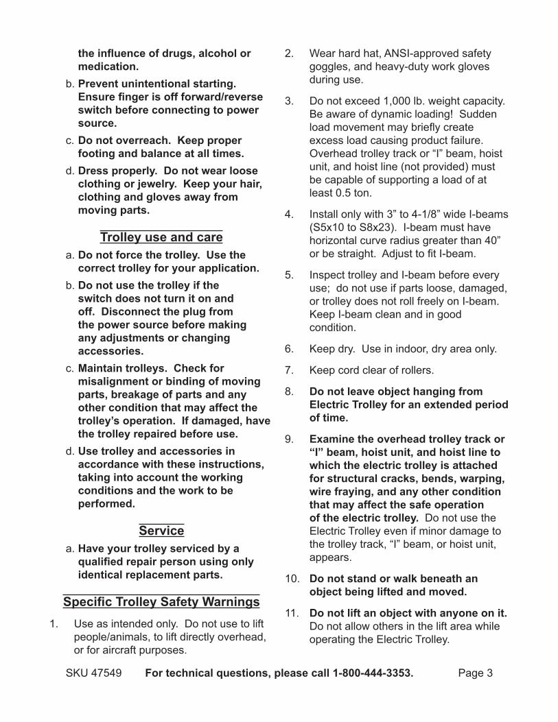
Specific Trolley Safety WarningsUse as intended only. Do not use to lift 1. people/animals, to lift directly overhead, or for aircraft purposes.
Wear hard hat, ANSI-approved safety 2. goggles, and heavy-duty work gloves during use.
Do not exceed 1,000 lb. weight capacity. 3. Be aware of dynamic loading! Sudden load movement may briefly create excess load causing product failure. Overhead trolley track or “I” beam, hoist unit, and hoist line (not provided) must be capable of supporting a load of at least 0.5 ton.
Install only with 3” to 4-1/8” wide I-beams 4. (S5x10 to S8x23). I-beam must have horizontal curve radius greater than 40” or be straight. Adjust to fit I-beam.
Inspect trolley and I-beam before every 5. use; do not use if parts loose, damaged, or trolley does not roll freely on I-beam. Keep I-beam clean and in good condition.
Keep dry. Use in indoor, dry area only.6.
Keep cord clear of rollers.7.
do not leave object hanging from 8. electric Trolley for an extended period of time.
examine the overhead trolley track or 9. “i” beam, hoist unit, and hoist line to which the electric trolley is attached for structural cracks, bends, warping, wire fraying, and any other condition that may affect the safe operation of the electric trolley. Do not use the Electric Trolley even if minor damage to the trolley track, “I” beam, or hoist unit, appears.
do not stand or walk beneath an 10. object being lifted and moved.
do not lift an object with anyone on it. 11. Do not allow others in the lift area while operating the Electric Trolley.

Page 4 For technical questions, please call 1-800-444-3353. SKU 47549
read and understand all instructions 12. and safety precautions as outlined in the manufacturer’s manual for the object you are lifting. Always use the manufacturer’s recommended lifting points.
use extreme caution when raising or 13. lowering an object. Do not allow the load to suddenly release. Slowly and carefully apply and release the load.
To avoid accidental load shifting/14. swinging, make sure the object being lifted is vertically in line with the electric trolley.
do not leave the electric trolley and 15. hoist unit unattended when it is under a load. Whenever the Electric Trolley and hoist unit is under a load there is a very large amount of force that has been stored in the hoist line (not provided) which must be controlled until the load is relaxed.
Before lowering an object, remove 16. tool trays, stands, and all other tools and equipment from under the object.
Avoid unintentional starting. Prepare to 17. begin work before turning on the trolley.
This product is not a toy. Keep it out of 18. reach of children.
People with pacemakers should 19. consult their physician(s) before use. Electromagnetic fields in close proximity to heart pacemaker could cause pacemaker interference or pacemaker failure. In addition, people with pacemakers should: • Avoid operating alone. • Do not use with power switch locked on. • Properly maintain and inspect to avoid electrical shock. • Any power cord must be properly
grounded. Ground Fault Circuit Interrupter (GFCI) should also be implemented – it prevents sustained electrical shock.
WARNING: Handling the cord on this 20. product will expose you to lead, a chemical known to the State of California to cause cancer, and birth defects or other reproductive harm. Wash hands after handling. (California Health & Safety Code § 25249.5)
The warnings, precautions, and 21. instructions discussed in this instruction manual cannot cover all possible conditions and situations that may occur. It must be understood by the operator that common sense and caution are factors which cannot be built into this product, but must be supplied by the operator.
SaVe TheSe inSTrucTionS.
grounding To preVenT
elecTric ShocK and deaTh FroM incorrecT grounding Wire connecTion: Check with a qualified electrician if you are in doubt as to whether the outlet is properly grounded. do not modify the power cord plug provided with the trolley. never remove the grounding prong from the plug. do not use the trolley if the power cord or plug is damaged. if damaged, have it repaired by a service facility before use. if the plug will not fit the outlet, have a proper

Page 5For technical questions, please call 1-800-444-3353.SKU 47549
outlet installed by a qualified electrician.
grounded Trolleys: Trolleys with Three prong plugs
3-prong plug and outlet
Trolleys marked with “Grounding 1. Required” have a three wire cord and three prong grounding plug. The plug must be connected to a properly grounded outlet. If the trolley should electrically malfunction or break down, grounding provides a low resistance path to carry electricity away from the user, reducing the risk of electric shock. (See 3-prong plug and outlet.)
The grounding prong in the plug is 2. connected through the green wire inside the cord to the grounding system in the trolley. The green wire in the cord must be the only wire connected to the trolley’s grounding system and must never be attached to an electrically “live” terminal. (See 3-prong plug and outlet.)
The trolley must be plugged into an 3. appropriate outlet, properly installed and grounded in accordance with all codes and ordinances. The plug and outlet should look like those in the preceding illustration. (See 3-prong plug and outlet.)
double insulated Trolleys: Trolleys with Two prong plugs
outlets for 2-prong plug
Trolleys marked “Double Insulated” 1. do not require grounding. They have a special double insulation system which satisfies OSHA requirements and complies with the applicable standards of Underwriters Laboratories, Inc., the Canadian Standard Association, and the National Electrical Code.
Double insulated trolleys may be used in 2. either of the 120 volt outlets shown in the preceding illustration. (See outlets for 2-prong plug.)
extension cordsGrounded1. trolleys require a three wire extension cord. Double Insulated trolleys can use either a two or three wire extension cord.
As the distance from the supply outlet 2. increases, you must use a heavier gauge extension cord. Using extension cords with inadequately sized wire causes a serious drop in voltage, resulting in loss of power and possible trolley damage. (See Table a.)
The smaller the gauge number of the 3. wire, the greater the capacity of the cord. For example, a 14 gauge cord can carry a higher current than a 16 gauge cord. (See Table a.)

Page 6 For technical questions, please call 1-800-444-3353. SKU 47549
When using more than one extension 4. cord to make up the total length, make sure each cord contains at least the minimum wire size required. (See Table a.)
If you are using one extension cord for 5. more than one trolley, add the nameplate amperes and use the sum to determine the required minimum cord size. (See Table a.)
If you are using an extension cord 6. outdoors, make sure it is marked with the suffix “W-A” (“W” in Canada) to indicate it is acceptable for outdoor use.
Make sure the extension cord is properly 7. wired and in good electrical condition. Always replace a damaged extension cord or have it repaired by a qualified electrician before using it.
Protect the extension cords from sharp 8. objects, excessive heat, and damp or wet areas.
recoMMended MiniMuM Wire gauge For eXTenSion cordS* (120/240 VolT)
naMeplaTeaMpereS(at full load)
eXTenSion cord lengTh
25’ 50’ 75’ 100’ 150’0 – 2.0 18 18 18 18 16
2.1 – 3.4 18 18 18 16 143.5 – 5.0 18 18 16 14 125.1 – 7.0 18 16 14 12 12
7.1 – 12.0 18 14 12 10 -12.1 – 16.0 14 12 10 - -16.1 – 20.0 12 10 - - -
TaBle a* Based on limiting the line volt-age drop to five volts at 150% of
the rated amperes.
Symbology
Double Insulated
Canadian Standards Association
Underwriters Laboratories, Inc.
V~ Volts Alternating Current
a Amperes
n0 xxxx/min. No Load Revolutions per Minute (RPM)

Page 7For technical questions, please call 1-800-444-3353.SKU 47549
SpeciFicaTionSElectrical Input 120 V~ / 60 Hz / 0.9 A
Motor Speed 1400 RPM
Weight Capacity 1/2 Ton (1,000 lb.)Remote Control Cord Length 5-1/2’ Ft. Long
I-Beam CompatibilityUse With 3” to 4-1/8” Wide I-Beams (S5x10 to S8x23)40” minimum curve radius
unpacKingWhen unpacking, make sure that the
item is intact and undamaged. If any parts are missing or broken, please call Harbor Freight Tools at 1-800-444-3353 as soon as possible.
please note: For shipping purposes, the Hook Plates (19) have been installed upside down on the Electric Trolley. See “Trolley Set Up” for instructions on how to remove and reinstall properly.
operaTing inSTrucTionS read the enTire iMporTanT
SaFeTy inForMaTion section at the beginning of this manual including all text under subheadings therein before set up or use of this product.
Trolley Set up To preVenT
SeriouS injury FroM accidenTal operaTion: release load from the trolley, turn power Switch off and unplug trolley from its electrical outlet before performing inspection, maintenance, or cleaning.
Before mounting and use, make sure rail surfaces of beam are free of rust, imperfections, and debris which might prevent gliding of the rollers.
Designate a work area that is clean and 1. well-lit. The work area must not allow access by children or pets to prevent distraction and injury.
Route the power cord along a safe 2. path to reach the work area without creating a tripping hazard or exposing the power cord to possible damage. The power cord must reach the work area with enough extra length to allow free movement while working.
There must not be objects, such as utility 3. lines, nearby that will present a hazard while working.
Before operating, the Hook Plates 4. (19) must be removed and reinstalled properly.
please note: 5. When adjusting width of the Trolley to fit the I-Beam, make sure that the two Hook Plates (19) are always positioned directly below center of beam.
Page 8 For technical questions, please call 1-800-444-3353. SKU 47549
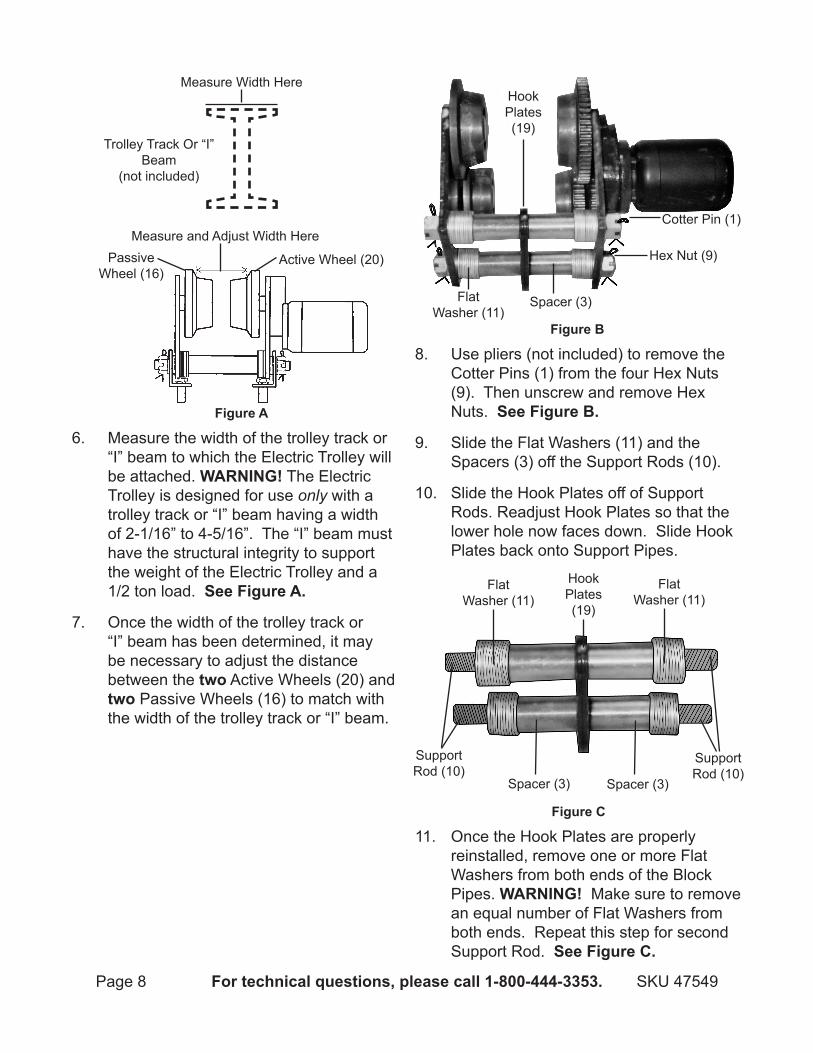
Measure and Adjust Width HerePassive
Wheel (16)Active Wheel (20)
Figure a
Measure Width Here
Trolley Track Or “I” Beam
(not included)
6. Measure the width of the trolley track or “I” beam to which the Electric Trolley will be attached. Warning! The Electric Trolley is designed for use only with a trolley track or “I” beam having a width of 2-1/16” to 4-5/16”. The “I” beam must have the structural integrity to support the weight of the Electric Trolley and a 1/2 ton load. See Figure a.
Once the width of the trolley track or 7. “I” beam has been determined, it may be necessary to adjust the distance between the two Active Wheels (20) and two Passive Wheels (16) to match with the width of the trolley track or “I” beam.
Figure B
Cotter Pin (1)
Hex Nut (9)
Hook Plates (19)
Spacer (3)Flat Washer (11)
8. Use pliers (not included) to remove the Cotter Pins (1) from the four Hex Nuts (9). Then unscrew and remove Hex Nuts. See Figure B.
Slide the Flat Washers (11) and the 9. Spacers (3) off the Support Rods (10).
Slide the Hook Plates off of Support 10. Rods. Readjust Hook Plates so that the lower hole now faces down. Slide Hook Plates back onto Support Pipes.
Figure c
Flat Washer (11)
Flat Washer (11)
Spacer (3) Spacer (3)
Hook Plates (19)
Support Rod (10)
Support Rod (10)
11. Once the Hook Plates are properly reinstalled, remove one or more Flat Washers from both ends of the Block Pipes. Warning! Make sure to remove an equal number of Flat Washers from both ends. Repeat this step for second Support Rod. See Figure c.

Page 9For technical questions, please call 1-800-444-3353.SKU 47549
Measure the width between the two 12. Active Wheels and two Passive Wheels; it should be slightly less than the measured width of the trolley track or “I” beam.
To expand width of the rollers, add equal 13. quantity of washers between Spacers (3) and the welded flanges of the Right and Left Flames (12, 22). cauTion! Add equal number of Washers between the four Nuts and Frames. When tightening, you may need to add or remove washers to enable clots in the nuts to align with pin-holes at end of Support Rods (10).
Passive Wheel (16)
Active Wheel (20)
Figure d
Right Frame (16) Left Frame
(22)
14. Once proper width is reached, remove the Right Frame (12) from the unit. Warning! Make sure the Hex Nuts below the Left Frame (22) are securely fastened onto the Support Pipes and locked into place using the Cotter Pins. See Figure d.
Figure e
I-beam
Hook Plates (19)
15. With assistance, position Passive Wheels on trolley track or “I” beam. Then position Left Frame and the remainder of the unit on the opposite side of the I-beam. See Figure e.
Slide the Support Rods through the 16. mounting holes on the Right Frame and fasten securely using the Hex Nuts. Lock the Hex Nuts in place using the Cotter Pins.
Attach the hoist (not included) to the 17. mounting hole at the bottom of the Hook Plates.
noTe: 18. A Right Angle Iron (2) and a Left Angle Iron (5) are included as adapters for the Electric Trolley. Depending on the type of hoist used, it may be necessary to replace the Hook Plates with the Angle Irons, following the same installation steps. If necessary, refer to the manufacturer’s instruction manual of the hoist to see which would work better with this Electric Trolley.
Allow the Handle (36, 38) to hang 19. vertically and within easy reach of the operator.
general operating instructions
Figure F
Switch (35) Handle (36, 38)
ReverseForward
1. To move Trolly along trolley track or I-beam, press the Switch (35). See direction indicator arrows adjacent to the Switch. To stop, release button. See Figure F.
To prevent accidents, release the Switch 2. and disconnect its power supply after use.

Page 10 For technical questions, please call 1-800-444-3353. SKU 47549
MainTenance and SerVicing
procedures not explained in this manual must be performed only by a qualified technician.
To preVenT SeriouS injury
FroM accidenTal operaTion: release load from the trolley, turn power Switch off and unplug trolley from its electrical outlet before performing inspection, maintenance, or cleaning.
To preVenT SeriouS injury FroM Trolley Failure: do not use damaged equipment. if abnormal noise or vibration occurs, have the problem corrected before further use.
BeFore each uSe,1. inspect general condition of Electric Trolley. Check for
loose hardware, misalignment or binding of moving parts, cracked or broken parts, damaged electrical wiring, and any condition that may affect its operation.
periodically2. , use a premium quality, lightweight machine oil to lubricate all moving parts. Use a premium quality, heavy-weight grease to lubricate surfaces of Passive Wheels and Active Wheels that contact with I-beam.
3. Warning! if the supply cord is damaged, it must be replaced only by a qualified service technician.
Troubleshootingproblem possible causes likely Solutions
Trolley will not start. Cord not connected.1. No power at outlet. 2.
Internal damage or wear. 3.
Check that cord is plugged in.1. Check power at outlet. If outlet is unpowered, 2. turn off trolley and check circuit breaker. If breaker is tripped, make sure circuit is right capacity for trolley and circuit has no other loads.Have technician service trolley.3.
Trolley operates slowly.
Extension cord too long or wire size too small.
Eliminate use of extension cord. If an extension cord is needed, use shorter/heavier gauge cord. See Extension Cords in GROUNDING section.
Excessive rattling. Internal damage or wear. Have technician service trolley.Overheating. Forcing trolley to work too fast/1.
long.Motor being strained by long or 2. small diameter extension cord.
Allow trolley to work at its own rate.1. Eliminate use of extension cord. If an extension 2. cord is needed, use one with the proper diameter for its length and load. See Extension Cords in GROUNDING section.
Follow all safety precautions whenever diagnosing or servicing the trolley. disconnect power supply before service.

Page 11For technical questions, please call 1-800-444-3353.SKU 47549
part description Qty.1 Cotter Pin 42 Right Angle Iron 13 Spacer 44 Gear Shaft 15 Left Angle Iron 16 Gear 17 Screw (M5 x 10) 48 Motor 19 Hex Nut 4
10 Support Rod 211 Flat Washer (M18 x 32 x 3mm) 4812 Right Frame 113 Internal O-Ring 114 Snap Ring 115 Roll Bearing 116 Passive Wheel 217 External O-Ring 118 Retaining Ring 119 Hook Plate 220 Active Wheel 221 Roll Bearing 122 Left Frame 1
part description Qty.23 Gear 124 Roll Bearing 125 Gear Box 126 Flat Washer 427 Spring Washer 428 Screw (M6 x 1.0 x 18mm) 429 Cable Sheath 130 Screw (M3 x 14) 431 Junction Box 132 Pressing Board 133 Screw (M4 x 14) 434 Cord/Plug 135 Switch 136 Front Handle Cover 137 Capacitor 138 Rear Handle Cover 139 Wire Sheath 140 Screw (M3.5 x 20) 441 Insert Board 142 Insert Board Cover 143 Cable 1
pleaSe read The FolloWing careFullyTHE MANUFACTURER AND/OR DISTRIBUTOR HAS PROVIDED THE PARTS LIST AND ASSEMBLy DIAGRAM IN THIS MANUAL AS A REFERENCE TOOL ONLy. NEITHER THE MANUFACTURER OR DISTRIBUTOR MAKES ANy REPRESENTATION OR WARRANTy OF ANy KIND TO THE BUyER THAT HE OR SHE IS qUALIFIED TO MAKE ANy REPAIRS TO THE PRODUCT, OR THAT HE OR SHE IS qUALIFIED TO REPLACE ANy PARTS OF THE PRODUCT. IN FACT, THE MANUFACTURER AND/OR DISTRIBUTOR ExPRESSLy STATES THAT ALL REPAIRS AND PARTS REPLACEMENTS SHOULD BE UNDERTAKEN By CERTIFIED AND LICENSED TECHNICIANS, AND NOT By THE BUyER. THE BUyER ASSUMES ALL RISK AND LIABILITy ARISING OUT OF HIS OR HER REPAIRS TO THE ORIGINAL PRODUCT OR REPLACEMENT PARTS THERETO, OR ARISING OUT OF HIS OR HER INSTALLATION OF REPLACEMENT PARTS THERETO.
parTS liST

Page 12 For technical questions, please call 1-800-444-3353. SKU 47549
aSSeMBly diagraM
record product’s Serial number here: note: If product has no serial number, record month and year of purchase instead.
note: Some parts are listed and shown for illustration purposes only, and are not available individually as replacement parts.