Embed Size (px)
Citation preview

materials
Article
Enhancement of Dynamic Damping in Eco-FriendlyRailway Concrete Sleepers Using Waste-TyreCrumb Rubber
Sakdirat Kaewunruen 1,2,* ID , Dan Li 2, Yu Chen 2 and Zhechun Xiang 2
1 Birmingham Centre for Railway Research and Education, University of Birmingham,Birmingham B152TT, UK
2 Department of Civil Engineering, School of Engineering, University of Birmingham,Birmingham B152TT, UK; [email protected] (D.L.); [email protected] (Y.C.);[email protected] (Z.X.)
* Correspondence: [email protected]; Tel.: +44-(0)-1214-142-670
Received: 20 June 2018; Accepted: 6 July 2018; Published: 9 July 2018
Abstract: There is no doubt that the use of waste rubber in concrete applications is a genius alternativebecause Styrene is the main component of rubber, which has a strong toxicity and is harmful tohumans. Therefore, it will significantly reduce impacts on the environment when waste rubber can berecycled for genuine uses. In this paper, the dynamic properties of high-strength rubberised concretehave been investigated by carrying out various experiments to retain the compressive strength,tensile strength, flexural strength, electrical resistivity, and damping characteristics by replacing fineaggregates with micro-scale crumb rubber. Over 20 variations of concrete mixes have been performed.The experimental results confirm that a decrease in the compressive strength can be expected whenthe rubber content is increased. The new findings demonstrate that the high-strength concrete canbe enhanced by optimal rubber particles in order to improve splitting tensile and flexural strengths,damping properties, and electrical resistivity. It is therefore recommended to consider the use ofrubberised concrete (up to 10 wt. % crumb rubber) in designing railway sleepers as this will improvethe service life of railway track systems and reduce wastes to the environment.
Keywords: crumb rubber; high-strength concrete; damping; dynamic moduli; railway application;recycled material
1. Introduction
At the beginning of the last century, with the development of science and technology, the reductionof forest resources led to the production of steel and concrete railway sleepers rather than wood [1–3].Since railway sleepers are effective but expensive, reinforced concrete has been used as a reliableand more efficient material for railway sleepers since the 1950s [4]. On the other hand, the rapiddevelopment of the automotive industry has led to the rapid development of the rubber tire industryand brought about the dilemma of how to deal with rubber waste that poses a serious threat tothe environment.
Recently, many researches have proposed and encouraged the use of waste rubber in concreteto improve its performance [5–7]. More precisely, in the railway sector the rubber concrete sleepershave known a high-demand due to its efficiency in high-intensity pressure vibration environment.In this study, the crumb rubber is replacing the fine aggregates in the concrete sleepers in order toevaluate their ability to absorb the vibration energy. While it is expected to have a material withbetter performances than conventional concrete, the reason behind this evaluation is to create a rubber
Materials 2018, 11, 1169; doi:10.3390/ma11071169 www.mdpi.com/journal/materials
Materials 2018, 11, 1169 2 of 20
concrete that can maintain its strength at an acceptable level, thus enhancing the performance andsustainability of the railway track systems exposed to high-intensity impact loading conditions [8–10].
The purpose of this paper is to highlight the sensitivity of dynamic properties of the high-strengthconcrete to crumb rubber inclusion as well as its capability in meeting the standards of railway concretesleepers’ manufacturing. Different proportions of crumb rubber with different particle sizes (75, 180,and 400 µm) have been used in order to analyse their effects on the compressive strength, splittingtensile and flexural strengths, electrical resistivity and damping properties of the rubberised concrete.
2. Railway Applications
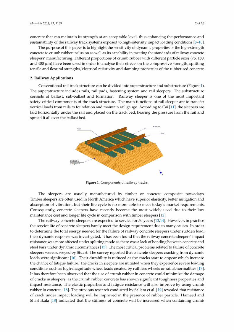
Conventional rail track structure can be divided into superstructure and substructure (Figure 1).The superstructure includes rails, rail pads, fastening system and rail sleepers. The substructureconsists of ballast, sub-ballast and formation. Railway sleeper is one of the most importantsafety-critical components of the track structure. The main functions of rail sleeper are to transfervertical loads from rails to foundation and maintain rail gauge. According to Cai [11], the sleepers arelaid horizontally under the rail and placed on the track bed, bearing the pressure from the rail andspread it all over the ballast bed.
Materials 2018, 11, x FOR PEER REVIEW 2 of 20
concrete that can maintain its strength at an acceptable level, thus enhancing the performance and sustainability of the railway track systems exposed to high-intensity impact loading conditions [8–10].
The purpose of this paper is to highlight the sensitivity of dynamic properties of the high-strength concrete to crumb rubber inclusion as well as its capability in meeting the standards of railway concrete sleepers’ manufacturing. Different proportions of crumb rubber with different particle sizes (75, 180, and 400 µm) have been used in order to analyse their effects on the compressive strength, splitting tensile and flexural strengths, electrical resistivity and damping properties of the rubberised concrete.
2. Railway Applications
Conventional rail track structure can be divided into superstructure and substructure (Figure 1). The superstructure includes rails, rail pads, fastening system and rail sleepers. The substructure consists of ballast, sub-ballast and formation. Railway sleeper is one of the most important safety-critical components of the track structure. The main functions of rail sleeper are to transfer vertical loads from rails to foundation and maintain rail gauge. According to Cai [11], the sleepers are laid horizontally under the rail and placed on the track bed, bearing the pressure from the rail and spread it all over the ballast bed.
Figure 1. Components of railway tracks.
The sleepers are usually manufactured by timber or concrete composite nowadays. Timber sleepers are often used in North America which have superior elasticity, better mitigation and absorption of vibration, but their life cycle is no more able to meet today’s market requirements. Consequently, concrete sleepers have recently become the most widely used due to their low maintenance cost and longer life cycle in comparison with timber sleepers [12].
The railway concrete sleepers are expected to service for 50 years [13,14]. However, in practice the service life of concrete sleepers barely meet the design requirement due to many causes. In order to determine the total energy needed for the failure of railway concrete sleepers under sudden load, their dynamic response was investigated. It has been found that the railway concrete sleepers’ impact resistance was more affected under splitting mode as there was a lack of bonding between concrete and steel bars under dynamic circumstances [15]. The most critical problems related to failure of concrete sleepers were surveyed by Stuart. The survey reported that concrete sleepers cracking from dynamic loads were significant [16]. Their durability is reduced as the cracks start to appear which increase the chance of fatigue failure. The cracks in sleepers are initiated when they experience severe loading conditions such as high-magnitude wheel loads created by ruthless wheels or rail abnormalities [17]. It has therefore been observed that the use of crumb rubber in concrete could minimize the damage of cracks in sleepers, as the crumb rubber concrete has shown significant toughness properties and impact resistance. The elastic properties and fatigue resistance will also improve by using crumb rubber in concrete [18]. The previous research conducted by Sallam et al. [19] revealed that resistance of crack under impact loading will be improved in the presence of rubber particle. Hameed and Shashikala [18] indicated that the stiffness of concrete will be increased when containing crumb rubber under cyclic loads. The outcome of this research has indicated the dynamic
Figure 1. Components of railway tracks.
The sleepers are usually manufactured by timber or concrete composite nowadays.Timber sleepers are often used in North America which have superior elasticity, better mitigation andabsorption of vibration, but their life cycle is no more able to meet today’s market requirements.Consequently, concrete sleepers have recently become the most widely used due to their lowmaintenance cost and longer life cycle in comparison with timber sleepers [12].
The railway concrete sleepers are expected to service for 50 years [13,14]. However, in practicethe service life of concrete sleepers barely meet the design requirement due to many causes. In orderto determine the total energy needed for the failure of railway concrete sleepers under sudden load,their dynamic response was investigated. It has been found that the railway concrete sleepers’ impactresistance was more affected under splitting mode as there was a lack of bonding between concrete andsteel bars under dynamic circumstances [15]. The most critical problems related to failure of concretesleepers were surveyed by Stuart. The survey reported that concrete sleepers cracking from dynamicloads were significant [16]. Their durability is reduced as the cracks start to appear which increasethe chance of fatigue failure. The cracks in sleepers are initiated when they experience severe loadingconditions such as high-magnitude wheel loads created by ruthless wheels or rail abnormalities [17].It has therefore been observed that the use of crumb rubber in concrete could minimize the damageof cracks in sleepers, as the crumb rubber concrete has shown significant toughness properties andimpact resistance. The elastic properties and fatigue resistance will also improve by using crumbrubber in concrete [18]. The previous research conducted by Sallam et al. [19] revealed that resistanceof crack under impact loading will be improved in the presence of rubber particle. Hameed andShashikala [18] indicated that the stiffness of concrete will be increased when containing crumb

Materials 2018, 11, 1169 3 of 20
rubber under cyclic loads. The outcome of this research has indicated the dynamic property of crumbrubber concrete through various experiments which provide important data for future railway sleeperdurability design.
3. Methods
3.1. Rubber Wastes and Their Applications
The large amount of abandoned waste tyres (Figure 2) while handled and removed quicklywill certainly impact the environment. Common solid waste disposal methods like incinerated andlandfilled are not suitable for this kind of waste as they lead to the release of toxic substances whichresults in serious contaminations of underground water systems. The thousands of hectares of landfillsnot only occupy sites that can have better usages, but also contribute to bacteria and mosquitoesbreeding, causing infectious diseases and blazes [20].
Materials 2018, 11, x FOR PEER REVIEW 3 of 20
property of crumb rubber concrete through various experiments which provide important data for future railway sleeper durability design.
3. Methods
3.1. Rubber Wastes and Their Applications
The large amount of abandoned waste tyres (Figure 2) while handled and removed quickly will certainly impact the environment. Common solid waste disposal methods like incinerated and landfilled are not suitable for this kind of waste as they lead to the release of toxic substances which results in serious contaminations of underground water systems. The thousands of hectares of landfills not only occupy sites that can have better usages, but also contribute to bacteria and mosquitoes breeding, causing infectious diseases and blazes [20].
Figure 2. Waste tyres.
As early as 1976, there was a patent for old tyres usage in the United States [21,22]. Nowadays, more granulation methods appeared, such as extraction of steel fibres from waste tyres as reinforcement in concrete is now possible [6]. Some researchers reported that the crumb rubber, when added to ballasted tracks, resulted in better absorption of the vibration impact energy and improved their life cycle [23]. More researches devoted to the possibility of partially replacing aggregates with rubber particles (Figure 3) as an eco-friendly alternative while dealing with rubber waste [24], and also improving the concrete damping characteristics [25].
Figure 3. Crumb rubber concrete.
3.2. Relevant Previous Studies
Most studies have shown that the replacement of the fine aggregates by crumb rubber in concrete will reduce its strength to a certain extent, and the degree of decrease in strength depends on both the particle size and the amount of addition [26]. Still, other studies reported many other benefits of using rubber in concrete. Rubber particles can act as an air-entraining agent and hence providing concrete with a better freeze-cycle protection [27]. Thermal resistance also presents a challenge for concrete sleepers, and since rubber has good heat insulation it was found that the crumb
Figure 2. Waste tyres.
As early as 1976, there was a patent for old tyres usage in the United States [21,22]. Nowadays,more granulation methods appeared, such as extraction of steel fibres from waste tyres as reinforcementin concrete is now possible [6]. Some researchers reported that the crumb rubber, when added toballasted tracks, resulted in better absorption of the vibration impact energy and improved their lifecycle [23]. More researches devoted to the possibility of partially replacing aggregates with rubberparticles (Figure 3) as an eco-friendly alternative while dealing with rubber waste [24], and alsoimproving the concrete damping characteristics [25].
Materials 2018, 11, x FOR PEER REVIEW 3 of 20
property of crumb rubber concrete through various experiments which provide important data for future railway sleeper durability design.
3. Methods
3.1. Rubber Wastes and Their Applications
The large amount of abandoned waste tyres (Figure 2) while handled and removed quickly will certainly impact the environment. Common solid waste disposal methods like incinerated and landfilled are not suitable for this kind of waste as they lead to the release of toxic substances which results in serious contaminations of underground water systems. The thousands of hectares of landfills not only occupy sites that can have better usages, but also contribute to bacteria and mosquitoes breeding, causing infectious diseases and blazes [20].
Figure 2. Waste tyres.
As early as 1976, there was a patent for old tyres usage in the United States [21,22]. Nowadays, more granulation methods appeared, such as extraction of steel fibres from waste tyres as reinforcement in concrete is now possible [6]. Some researchers reported that the crumb rubber, when added to ballasted tracks, resulted in better absorption of the vibration impact energy and improved their life cycle [23]. More researches devoted to the possibility of partially replacing aggregates with rubber particles (Figure 3) as an eco-friendly alternative while dealing with rubber waste [24], and also improving the concrete damping characteristics [25].
Figure 3. Crumb rubber concrete.
3.2. Relevant Previous Studies
Most studies have shown that the replacement of the fine aggregates by crumb rubber in concrete will reduce its strength to a certain extent, and the degree of decrease in strength depends on both the particle size and the amount of addition [26]. Still, other studies reported many other benefits of using rubber in concrete. Rubber particles can act as an air-entraining agent and hence providing concrete with a better freeze-cycle protection [27]. Thermal resistance also presents a challenge for concrete sleepers, and since rubber has good heat insulation it was found that the crumb
Figure 3. Crumb rubber concrete.
3.2. Relevant Previous Studies
Most studies have shown that the replacement of the fine aggregates by crumb rubber in concretewill reduce its strength to a certain extent, and the degree of decrease in strength depends on boththe particle size and the amount of addition [26]. Still, other studies reported many other benefits

Materials 2018, 11, 1169 4 of 20
of using rubber in concrete. Rubber particles can act as an air-entraining agent and hence providingconcrete with a better freeze-cycle protection [27]. Thermal resistance also presents a challenge forconcrete sleepers, and since rubber has good heat insulation it was found that the crumb rubber canincrease the thermal resistance of concrete to about 18.52% [28]. Conventional concrete has betterfire resistance than crumb rubber concrete as the rubber is a flammable material and its particleson the concrete surfaces can easily be burnt [29]. The dynamic properties are very important in therailway track design process. For concrete sleepers, cracking could be caused by wheel–rail interactionforce which can be divided into dynamic load and impact load [30]. Dynamic load is wheel–railinteraction under normal situation, whereas impact load is also wheel–rail interaction caused bydefects in wheel or rail. In durability design, sleepers need to withstand dynamic load and impactload. However, the dynamic testing data of crumb rubber concrete is not enough for concrete sleeperdesign. Therefore, investigation of dynamic properties is necessary for new material concrete sleeperdesign [31].
4. Materials
The emphasis of this study is placed on the application of recycled crumb rubber to enhancedynamic damping of structural concrete for railway applications. To enable the industry application,specific requirements must be complied (e.g., EN 13230 [32]). The materials for the concrete mix arethus specifically chosen to meet standard requirements.
4.1. Cement
As described in BS EN 197-1 [33], the Portland Cement Type I (CEM I) could be used to mixconcrete which has a characteristic strength of 55 MPa.
4.2. Silica Fume
Silica fume is a grey powder that belongs to a broad class of siliceous and aluminous materialscalled “Pozzolans”, which plays a particular role in filling the pores between the cement. Adding theright amount of silica fume contributes to improving the compressive and flexural strengths,impermeability, corrosion/impact resistances. These improvements are due to the consummation ofcalcium hydroxides, produced by the hydration of cement, by the silicon dioxide SiO2 [34] present inthe composition of the silica fume as summarized in Table 1. The use of silica fume in this study is tocompensate the loss of strength when crumb rubber is used.
Table 1. Chemical and Physical Properties of Undensified Silica Fume [35].
No. Properties Value
1 SiO2 Minimum 90%2 Loss of Ignition Maximum 3%3 Coarse Particles > 45 µm Maximum 1.5% (tested on undensified)4 Bulk Density (U) 200–350 kg/m3
5 Bulk Density (D) 500–700 kg/m3
4.3. Coarse Aggregates
Coarse aggregate refers to pebbles and gravel, while fine aggregate refers to natural sand andartificial sand. Aggregates with a particle size greater than 4.75 mm are called coarse aggregates andaggregates with a diameter of 4.75 mm or less are called fine aggregates. Using a vibrating sieve toscreen out usable gravels, the gradation table is produced as shown in Table 2. For concrete sleepers,all aggregates should comply with BS EN 12620 [36].
Materials 2018, 11, 1169 5 of 20
Table 2. Gradation of aggregates.
No. Sieves (mm) Weight Retained (g) % Retained Cumulative Retained % Finer
1 20 0 0% 0 100%2 16 0 0% 0 100%3 10 835 21% 21% 79%4 6.7 2710 67.5% 88.5% 11.5%5 4.75 355 9% 97.5% 2.5%6 Base 100 2.5% 100% 0%
Total 4000 g
4.4. Water
The water used to mix concrete should be clean and easy to obtain on site, in accordance to BS EN206-1 [37].
4.5. Admixture
Concrete admixtures are substances, once added to the mixture, that improve and adjust theperformance of concrete. Typically, according to BS EN 934-2 [33], they cannot be added in excess of5% of the cement content. The most common such admixtures are water-reducing agents, set retarder,air-entraining admixture, etc.
4.6. Concrete
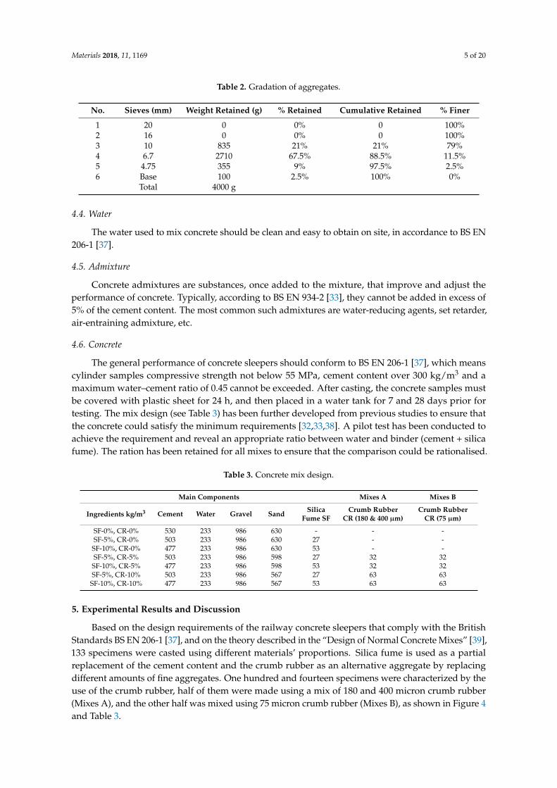
The general performance of concrete sleepers should conform to BS EN 206-1 [37], which meanscylinder samples compressive strength not below 55 MPa, cement content over 300 kg/m3 and amaximum water–cement ratio of 0.45 cannot be exceeded. After casting, the concrete samples mustbe covered with plastic sheet for 24 h, and then placed in a water tank for 7 and 28 days prior fortesting. The mix design (see Table 3) has been further developed from previous studies to ensure thatthe concrete could satisfy the minimum requirements [32,33,38]. A pilot test has been conducted toachieve the requirement and reveal an appropriate ratio between water and binder (cement + silicafume). The ration has been retained for all mixes to ensure that the comparison could be rationalised.
Table 3. Concrete mix design.
Main Components Mixes A Mixes B
Ingredients kg/m3 Cement Water Gravel Sand SilicaFume SF
Crumb RubberCR (180 & 400 µm)
Crumb RubberCR (75 µm)
SF-0%, CR-0% 530 233 986 630 - - -SF-5%, CR-0% 503 233 986 630 27 - -
SF-10%, CR-0% 477 233 986 630 53 - -SF-5%, CR-5% 503 233 986 598 27 32 32
SF-10%, CR-5% 477 233 986 598 53 32 32SF-5%, CR-10% 503 233 986 567 27 63 63
SF-10%, CR-10% 477 233 986 567 53 63 63
5. Experimental Results and Discussion
Based on the design requirements of the railway concrete sleepers that comply with the BritishStandards BS EN 206-1 [37], and on the theory described in the “Design of Normal Concrete Mixes” [39],133 specimens were casted using different materials’ proportions. Silica fume is used as a partialreplacement of the cement content and the crumb rubber as an alternative aggregate by replacingdifferent amounts of fine aggregates. One hundred and fourteen specimens were characterized by theuse of the crumb rubber, half of them were made using a mix of 180 and 400 micron crumb rubber(Mixes A), and the other half was mixed using 75 micron crumb rubber (Mixes B), as shown in Figure 4and Table 3.
Materials 2018, 11, 1169 6 of 20Materials 2018, 11, x FOR PEER REVIEW 6 of 20
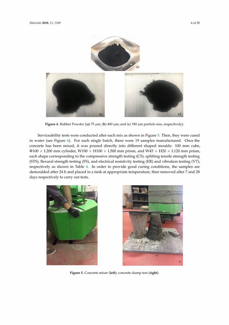
Figure 4. Rubber Powder ((a) 75 µm; (b) 400 µm; and (c) 180 µm particle size, respectively).
Serviceability tests were conducted after each mix as shown in Figure 5. Then, they were cured in water (see Figure 6). For each single batch, there were 19 samples manufactured. Once the concrete has been mixed, it was poured directly into different shaped moulds: 100 mm cube, Φ100 × L200 mm cylinder, W100 × H100 × L500 mm prism, and W45 × H20 × L120 mm prism, each shape corresponding to the compressive strength testing (CS), splitting tensile strength testing (STS), flexural strength testing (FS), and electrical resistivity testing (ER) and vibration testing (VT), respectively as shown in Table 4. In order to provide good curing conditions, the samples are demoulded after 24 h and placed in a tank at appropriate temperature, then removed after 7 and 28 days respectively to carry out tests.
Figure 5. Concrete mixer (left); concrete slump test (right).
a)
b) c)
Figure 4. Rubber Powder ((a) 75 µm; (b) 400 µm; and (c) 180 µm particle size, respectively).
Serviceability tests were conducted after each mix as shown in Figure 5. Then, they were curedin water (see Figure 6). For each single batch, there were 19 samples manufactured. Once theconcrete has been mixed, it was poured directly into different shaped moulds: 100 mm cube,Φ100 × L200 mm cylinder, W100 × H100 × L500 mm prism, and W45 × H20 × L120 mm prism,each shape corresponding to the compressive strength testing (CS), splitting tensile strength testing(STS), flexural strength testing (FS), and electrical resistivity testing (ER) and vibration testing (VT),respectively as shown in Table 4. In order to provide good curing conditions, the samples aredemoulded after 24 h and placed in a tank at appropriate temperature, then removed after 7 and 28days respectively to carry out tests.
Materials 2018, 11, x FOR PEER REVIEW 6 of 20
Figure 4. Rubber Powder ((a) 75 µm; (b) 400 µm; and (c) 180 µm particle size, respectively).
Serviceability tests were conducted after each mix as shown in Figure 5. Then, they were cured in water (see Figure 6). For each single batch, there were 19 samples manufactured. Once the concrete has been mixed, it was poured directly into different shaped moulds: 100 mm cube, Φ100 × L200 mm cylinder, W100 × H100 × L500 mm prism, and W45 × H20 × L120 mm prism, each shape corresponding to the compressive strength testing (CS), splitting tensile strength testing (STS), flexural strength testing (FS), and electrical resistivity testing (ER) and vibration testing (VT), respectively as shown in Table 4. In order to provide good curing conditions, the samples are demoulded after 24 h and placed in a tank at appropriate temperature, then removed after 7 and 28 days respectively to carry out tests.
Figure 5. Concrete mixer (left); concrete slump test (right).
a)
b) c)
Figure 5. Concrete mixer (left); concrete slump test (right).

Materials 2018, 11, 1169 7 of 20Materials 2018, 11, x FOR PEER REVIEW 7 of 20
Figure 6. Specimen shapes (left); curing tank (right).
Table 4. Types of moulds and corresponding tests.
Mould Type Number of Samples per Mix Type of Test Cube 100 mm 6 Compressive strength
Cylinder Φ 100 × L200 mm 3 Splitting Tensile Strength Prism W100 × H100 × L500 mm 6 Flexural Strength Prism W45 × H20 × L120 mm 4 Electrical Resistivity, Vibration, and Damping
5.1. Compressive Strength
The compressive strength tests (Figure 7) were carried out according to BS EN 12390-3 [40]. With a total of six cube samples per batch, previously removed from the tank and placed in an oven one day in advance in order to dry, three samples were tested after 7 days and the other half after 28 days. The results of the compressive tests are summarised in Figure 8.
Figure 7. Compressive test setup.
Figure 6. Specimen shapes (left); curing tank (right).
Table 4. Types of moulds and corresponding tests.
Mould Type Number of Samples per Mix Type of Test
Cube 100 mm 6 Compressive strengthCylinder Φ 100 × L200 mm 3 Splitting Tensile Strength
Prism W100 × H100 × L500 mm 6 Flexural StrengthPrism W45 × H20 × L120 mm 4 Electrical Resistivity, Vibration, and Damping
5.1. Compressive Strength
The compressive strength tests (Figure 7) were carried out according to BS EN 12390-3 [40].With a total of six cube samples per batch, previously removed from the tank and placed in an ovenone day in advance in order to dry, three samples were tested after 7 days and the other half after28 days. The results of the compressive tests are summarised in Figure 8.
Materials 2018, 11, x FOR PEER REVIEW 7 of 20
Figure 6. Specimen shapes (left); curing tank (right).
Table 4. Types of moulds and corresponding tests.
Mould Type Number of Samples per Mix Type of Test Cube 100 mm 6 Compressive strength
Cylinder Φ 100 × L200 mm 3 Splitting Tensile Strength Prism W100 × H100 × L500 mm 6 Flexural Strength Prism W45 × H20 × L120 mm 4 Electrical Resistivity, Vibration, and Damping
5.1. Compressive Strength
The compressive strength tests (Figure 7) were carried out according to BS EN 12390-3 [40]. With a total of six cube samples per batch, previously removed from the tank and placed in an oven one day in advance in order to dry, three samples were tested after 7 days and the other half after 28 days. The results of the compressive tests are summarised in Figure 8.
Figure 7. Compressive test setup. Figure 7. Compressive test setup.

Materials 2018, 11, 1169 8 of 20Materials 2018, 11, x FOR PEER REVIEW 8 of 20
Figure 8. Compressive strength of crumb rubber concrete.
According to Figure 8, the results of compressive strength at 7 days and 28 days of experimental samples is shown. The reference concrete showed a compressive strength of 53.05 MPa at 7 days and 63.33 MPa at 28 days which shows good performance in compressive strength. The highest performance of compressive strength are the samples containing 5% and 10% silica fume, with 73.13 MPa and 76.5 MPa, respectively. Many previous literatures have indicated that the compressive strength would reduce in replacement of fine aggregate with crumb rubber. The results of this research also confirmed this phenomenon. In fact, all the samples with crumb rubber have less performance in compressive strength. There are only 2 samples containing crumb rubber that met the design requirements (55 MPa) according to BS EN 206-1 [37] in which they are 10% silica fume/5% 75 micro-crumb rubber and 10% silica fume/5% 400&180 micro-crumb rubber. The best performance of compressive strength crumb rubber concrete sample is 10% silica fume/5% 75 micro-crumb rubber which has 59.2 MPa compressive strength at 28 days and it is only 6.5% lower than reference concrete.
The 10% silica fume or 5% 400&180 micro-crumb rubber has a similar result which is 57.3 MPa. Obviously, the addition of crumb rubber negatively affected the concrete performance while the silica fume improved it. This has been proved by different authors who establish a proportional relation between the increase of crumb rubber content in the concrete mixture and the reduction in its compressive strength [41–43]. However, the rubber concrete containing a proportion of 10% silica fume and 5% crumb rubber has shown considerable results by reaching 59.20 MPa and 57.30 MPa at 28 days in both cases: 75 micron and the mix of 180 and 400 micron, respectively. The fact that the addition of 75 micron crumb rubber results in higher concrete compressive strength comparing to the mix of 180 and 400 micron by approximately 3.3% is due to the finer rubber particles that have a better ability in filling voids, thus offering a higher compressive strength [44]. Therefore, it has been deducted from the tests’ results of this study that the crumb rubber concrete can be considered as a reliable material for railway concrete sleepers, since its compressive strength meet the standard for sleepers manufacturing (55 MPa).
5.2. Splitting Tensile and Flexural Strengths
According to BS EN 12390-6 [45], cylindrical specimens are used to test the rubber concrete splitting test after 28 days. In order to stabilize the specimens during the test, a pad is placed between the bearing surface and the press plate of the machine forming a corresponding strip loading between the top and the bottom of the specimens (Figure 9). At the beginning of the test, the loading was carried out continuously and uniformly at a speed ranging from 0.02 to 0.05 MPa/s until it reached 30 N/mm2, the loading speed was then increased to range between 0.05 and 0.08 MPa/s until the end
0102030405060708090
Com
pres
sive
stre
ngth
(MPa
)
7 days
28 days
Figure 8. Compressive strength of crumb rubber concrete.
According to Figure 8, the results of compressive strength at 7 days and 28 days of experimentalsamples is shown. The reference concrete showed a compressive strength of 53.05 MPa at7 days and 63.33 MPa at 28 days which shows good performance in compressive strength.The highest performance of compressive strength are the samples containing 5% and 10% silicafume, with 73.13 MPa and 76.5 MPa, respectively. Many previous literatures have indicated that thecompressive strength would reduce in replacement of fine aggregate with crumb rubber. The results ofthis research also confirmed this phenomenon. In fact, all the samples with crumb rubber have lessperformance in compressive strength. There are only 2 samples containing crumb rubber that met thedesign requirements (55 MPa) according to BS EN 206-1 [37] in which they are 10% silica fume/5% 75micro-crumb rubber and 10% silica fume/5% 400&180 micro-crumb rubber. The best performance ofcompressive strength crumb rubber concrete sample is 10% silica fume/5% 75 micro-crumb rubberwhich has 59.2 MPa compressive strength at 28 days and it is only 6.5% lower than reference concrete.
The 10% silica fume or 5% 400&180 micro-crumb rubber has a similar result which is 57.3 MPa.Obviously, the addition of crumb rubber negatively affected the concrete performance while thesilica fume improved it. This has been proved by different authors who establish a proportionalrelation between the increase of crumb rubber content in the concrete mixture and the reduction inits compressive strength [41–43]. However, the rubber concrete containing a proportion of 10% silicafume and 5% crumb rubber has shown considerable results by reaching 59.20 MPa and 57.30 MPa at28 days in both cases: 75 micron and the mix of 180 and 400 micron, respectively. The fact that theaddition of 75 micron crumb rubber results in higher concrete compressive strength comparing tothe mix of 180 and 400 micron by approximately 3.3% is due to the finer rubber particles that have abetter ability in filling voids, thus offering a higher compressive strength [44]. Therefore, it has beendeducted from the tests’ results of this study that the crumb rubber concrete can be considered as areliable material for railway concrete sleepers, since its compressive strength meet the standard forsleepers manufacturing (55 MPa).
5.2. Splitting Tensile and Flexural Strengths
According to BS EN 12390-6 [45], cylindrical specimens are used to test the rubber concretesplitting test after 28 days. In order to stabilize the specimens during the test, a pad is placed betweenthe bearing surface and the press plate of the machine forming a corresponding strip loading betweenthe top and the bottom of the specimens (Figure 9). At the beginning of the test, the loading wascarried out continuously and uniformly at a speed ranging from 0.02 to 0.05 MPa/s until it reached30 N/mm2, the loading speed was then increased to range between 0.05 and 0.08 MPa/s until the end

Materials 2018, 11, 1169 9 of 20
of the test. The test is stopped when the specimen is damaged and the damage load is recorded at anaccuracy of 0.01 KN.
On the other hand, in order to measure the flexural strength of the rubberised concrete, several4-point bending tests (Figure 10) have been carried out on prism specimens at 28 days according to BSEN 12390-5 [46]. The specimens are placed on two roller supports and loaded from an upper roller at aconstant rate of 0.05 MPa/s, and the tests’ results stop recording once the specimens fail. The results ofboth tests are presented in each graph of Figure 11.
Materials 2018, 11, x FOR PEER REVIEW 9 of 20
of the test. The test is stopped when the specimen is damaged and the damage load is recorded at an accuracy of 0.01 KN.
On the other hand, in order to measure the flexural strength of the rubberised concrete, several 4-point bending tests (Figure 10) have been carried out on prism specimens at 28 days according to BS EN 12390-5 [46]. The specimens are placed on two roller supports and loaded from an upper roller at a constant rate of 0.05 MPa/s, and the tests’ results stop recording once the specimens fail. The results of both tests are presented in each graph of Figure 11.
Figure 9. Splitting tensile test.
Figure 10. 4-point bending test.
Figure 11. Splitting tensile strength of crumb rubber concrete.
According to BS EN 12390-6 [45], the splitting tensile strength of concrete at 28 days was calculated using the function below:
0 2 4 6 8
RFCSF/5%
SF/10%-5%/CR(400&180)SF/10%-10%/CR(400&180)
SF/10%-5%/CR(75)SF/10%-10%/CR(75)
Strength at 28 days
Flexural strength
Splitting tensile strength
Figure 9. Splitting tensile test.
Materials 2018, 11, x FOR PEER REVIEW 9 of 20
of the test. The test is stopped when the specimen is damaged and the damage load is recorded at an accuracy of 0.01 KN.
On the other hand, in order to measure the flexural strength of the rubberised concrete, several 4-point bending tests (Figure 10) have been carried out on prism specimens at 28 days according to BS EN 12390-5 [46]. The specimens are placed on two roller supports and loaded from an upper roller at a constant rate of 0.05 MPa/s, and the tests’ results stop recording once the specimens fail. The results of both tests are presented in each graph of Figure 11.
Figure 9. Splitting tensile test.
Figure 10. 4-point bending test.
Figure 11. Splitting tensile strength of crumb rubber concrete.
According to BS EN 12390-6 [45], the splitting tensile strength of concrete at 28 days was calculated using the function below:
0 2 4 6 8
RFCSF/5%
SF/10%-5%/CR(400&180)SF/10%-10%/CR(400&180)
SF/10%-5%/CR(75)SF/10%-10%/CR(75)
Strength at 28 days
Flexural strength
Splitting tensile strength
Figure 10. 4-point bending test.
Materials 2018, 11, x FOR PEER REVIEW 9 of 20
of the test. The test is stopped when the specimen is damaged and the damage load is recorded at an accuracy of 0.01 KN.
On the other hand, in order to measure the flexural strength of the rubberised concrete, several 4-point bending tests (Figure 10) have been carried out on prism specimens at 28 days according to BS EN 12390-5 [46]. The specimens are placed on two roller supports and loaded from an upper roller at a constant rate of 0.05 MPa/s, and the tests’ results stop recording once the specimens fail. The results of both tests are presented in each graph of Figure 11.
Figure 9. Splitting tensile test.
Figure 10. 4-point bending test.
Figure 11. Splitting tensile strength of crumb rubber concrete.
According to BS EN 12390-6 [45], the splitting tensile strength of concrete at 28 days was calculated using the function below:
0 2 4 6 8
RFCSF/5%
SF/10%-5%/CR(400&180)SF/10%-10%/CR(400&180)
SF/10%-5%/CR(75)SF/10%-10%/CR(75)
Strength at 28 days
Flexural strength
Splitting tensile strength
Figure 11. Splitting tensile strength of crumb rubber concrete.

Materials 2018, 11, 1169 10 of 20
According to BS EN 12390-6 [45], the splitting tensile strength of concrete at 28 days was calculatedusing the function below:
fct =2F
πLD(1)
where fct is the splitting tensile strength (MPa), & is the maximum load (N), L is the length of the lineof contact of the specimen (mm), and D is the designated cross-sectional dimension (mm).
Similarly to the compressive strength results, the increase in silica fume content clearly improvedthe splitting tensile strength by 30% comparing to conventional concrete, reaching a maximum valueof 3.85 MPa at 28 days as shown in Figure 11. Also, as expected from previous studies, the rubberpowder replacing fine aggregates has considerably decreased the splitting tensile strength, especiallywhen its amount is increased to 10% and mixed with 5% silica fume, leading to a minimum valuelower than the one obtained from the conventional concrete by 35% in the case of 75 micro rubber,and 30% in the case of mixing 180 and 400 micro rubber. Though, the proportions that seemed toshow better performance than normal concrete are the ones containing 10% silica fume: mixed with5% crumb rubber in the case of 180 and 400 micro rubber, and 10% in the case of 75 micro rubber(3.75 MPa and 3.54 MPa respectively).
Likewise, the flexural strength has been calculated following the British standard BS EN12390-5 [46]:
fc f =FI
d1d22
(2)
where fcf is the flexural strength (MPa), F is the maximum load (N), I is the length between rollersupports (mm), and d1 and d2 are the cross-sectional dimensions of specimen (mm).
As shown in Figure 11, similar trend was observed between the splitting tensile and the flexuralstrengths. The maximum value recorded is 7.34 MPa and the minimum is 5.02 MPa, both correspondto SF10%/CR0% and SF5%/CR10%, respectively. Same observations have been deducted in theflexural test, which are the improvement of concrete strength by increasing the silica fume content anddecreasing the crumb rubber proportion, and its deterioration in the opposite way. Many previousstudies have come to similar conclusions regarding both, splitting tensile and flexural strengths ofrubberised concrete, when replacing normal coarse aggregates with recycled rubber crumb [21,47,48].Yet, the specimens containing a combination of 10% silica fume and whether 5% of the 180&400 microrubber or 10% of 75 micro rubber have shown acceptable flexural strengths superior to plain concreteby 8% and 13%: 6.19 MPa and 6.49 MPa, respectively.
The tensile and flexural ratio can be calculated by:
tensile ratio =f ′tf ′c∗ 100% (3)
tensile ratio =f ′ff ′c∗ 100% (4)
The tensile ratio and flexural ratio have been calculated by Formulas (3) and (4) shown in Figure 12.Both the tensile and flexural ratio follow the same trend as flexural/splitting tensile strength. From thegraph, all the flexural ratio of crumb rubber concrete are more than 10%. The highest tensile/flexuralratio is 10% silica fume/10% 75 micro rubber, which are 8.78% and 16.10%, respectively. Non-crumbrubber samples show very low tensile ratio, they are: 4.69% for reference concrete, 5.03% for 5% silicafume concrete and 5.03% for 10% silica fume; 10% silica fume/10% 400 & 180 micro-crumb rubber hassimilar tensile ratio with non-crumb rubber sample, which is 5.11%.

Materials 2018, 11, 1169 11 of 20
Materials 2018, 11, x FOR PEER REVIEW 11 of 20
Figure 12. Splitting tensile and flexural ratio of crumb rubber concrete.
5.3. Electrical Resistivity
Generally, there are two main methods to measure the electrical resistance of cementitious materials: two-electrode method and four-electrode method [49]. In this study, the two-electrode method has been considered to test prism specimens at 28 days, after having been removed from the tank for natural drying prior for testing. Victor VC60B+, an insulation tester, has been used to determine the electrical resistance (ohm) of the specimens, by connecting leads to both their ends and setting the voltage at a constant value of 1000 Volts as shown in Figure 13. The results of the experiments, shown in Figure 12, are recorded 60 s later.
Figure 13. Electrical resistivity test.
After 28 days, the electrical resistance was measured then calculated using the resistance equation [22]:
휌 = 푘 ∗ 푅; 푘 =퐴퐿 (5)
where R is the resistance of concrete, k is a geometrical factor which depends on the size and shape of the specimen, A is the cross-sectional area perpendicular to the current, L is the height of the specimen.
Figure 12. Splitting tensile and flexural ratio of crumb rubber concrete.
5.3. Electrical Resistivity
Generally, there are two main methods to measure the electrical resistance of cementitiousmaterials: two-electrode method and four-electrode method [49]. In this study, the two-electrodemethod has been considered to test prism specimens at 28 days, after having been removed fromthe tank for natural drying prior for testing. Victor VC60B+, an insulation tester, has been used todetermine the electrical resistance (ohm) of the specimens, by connecting leads to both their endsand setting the voltage at a constant value of 1000 Volts as shown in Figure 13. The results of theexperiments, shown in Figure 12, are recorded 60 s later.
Materials 2018, 11, x FOR PEER REVIEW 11 of 20
Figure 12. Splitting tensile and flexural ratio of crumb rubber concrete.
5.3. Electrical Resistivity
Generally, there are two main methods to measure the electrical resistance of cementitious materials: two-electrode method and four-electrode method [49]. In this study, the two-electrode method has been considered to test prism specimens at 28 days, after having been removed from the tank for natural drying prior for testing. Victor VC60B+, an insulation tester, has been used to determine the electrical resistance (ohm) of the specimens, by connecting leads to both their ends and setting the voltage at a constant value of 1000 Volts as shown in Figure 13. The results of the experiments, shown in Figure 12, are recorded 60 s later.
Figure 13. Electrical resistivity test.
After 28 days, the electrical resistance was measured then calculated using the resistance equation [22]:
휌 = 푘 ∗ 푅; 푘 =퐴퐿 (5)
where R is the resistance of concrete, k is a geometrical factor which depends on the size and shape of the specimen, A is the cross-sectional area perpendicular to the current, L is the height of the specimen.
Figure 13. Electrical resistivity test.
After 28 days, the electrical resistance was measured then calculated using the resistanceequation [22]:
ρ = k ∗ R; k =AL
(5)
Materials 2018, 11, 1169 12 of 20
where R is the resistance of concrete, k is a geometrical factor which depends on the size and shape ofthe specimen, A is the cross-sectional area perpendicular to the current, L is the height of the specimen.
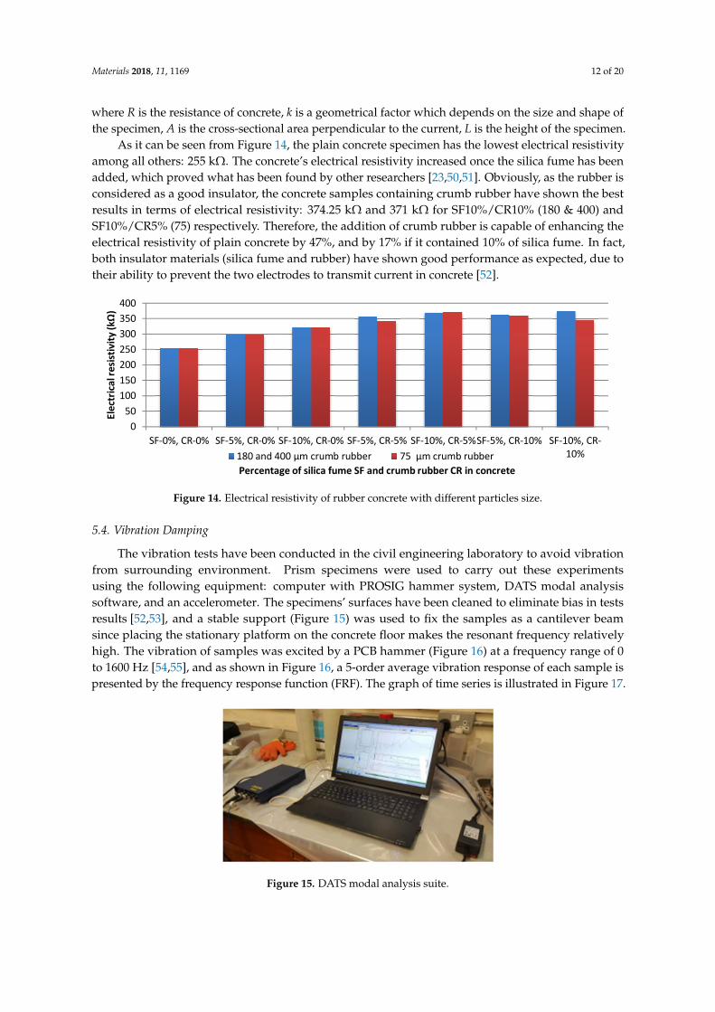
As it can be seen from Figure 14, the plain concrete specimen has the lowest electrical resistivityamong all others: 255 kΩ. The concrete’s electrical resistivity increased once the silica fume has beenadded, which proved what has been found by other researchers [23,50,51]. Obviously, as the rubber isconsidered as a good insulator, the concrete samples containing crumb rubber have shown the bestresults in terms of electrical resistivity: 374.25 kΩ and 371 kΩ for SF10%/CR10% (180 & 400) andSF10%/CR5% (75) respectively. Therefore, the addition of crumb rubber is capable of enhancing theelectrical resistivity of plain concrete by 47%, and by 17% if it contained 10% of silica fume. In fact,both insulator materials (silica fume and rubber) have shown good performance as expected, due totheir ability to prevent the two electrodes to transmit current in concrete [52].
Materials 2018, 11, x FOR PEER REVIEW 12 of 20
As it can be seen from Figure 14, the plain concrete specimen has the lowest electrical resistivity among all others: 255 kΩ. The concrete’s electrical resistivity increased once the silica fume has been added, which proved what has been found by other researchers [23,50,51]. Obviously, as the rubber is considered as a good insulator, the concrete samples containing crumb rubber have shown the best results in terms of electrical resistivity: 374.25 kΩ and 371 kΩ for SF10%/CR10% (180 & 400) and SF10%/CR5% (75) respectively. Therefore, the addition of crumb rubber is capable of enhancing the electrical resistivity of plain concrete by 47%, and by 17% if it contained 10% of silica fume. In fact, both insulator materials (silica fume and rubber) have shown good performance as expected, due to their ability to prevent the two electrodes to transmit current in concrete [52].
Figure 14. Electrical resistivity of rubber concrete with different particles size.
5.4. Vibration Damping
The vibration tests have been conducted in the civil engineering laboratory to avoid vibration from surrounding environment. Prism specimens were used to carry out these experiments using the following equipment: computer with PROSIG hammer system, DATS modal analysis software, and an accelerometer. The specimens’ surfaces have been cleaned to eliminate bias in tests results [52,53], and a stable support (Figure 15) was used to fix the samples as a cantilever beam since placing the stationary platform on the concrete floor makes the resonant frequency relatively high. The vibration of samples was excited by a PCB hammer (Figure 16) at a frequency range of 0 to 1600 Hz [54,55], and as shown in Figure 16, a 5-order average vibration response of each sample is presented by the frequency response function (FRF). The graph of time series is illustrated in Figure 17.
Figure 15. DATS modal analysis suite.
050
100150200250300350400
SF-0%, CR-0% SF-5%, CR-0% SF-10%, CR-0% SF-5%, CR-5% SF-10%, CR-5%SF-5%, CR-10% SF-10%, CR-10%
Elec
tric
al re
sistiv
ity (k
Ω)
Percentage of silica fume SF and crumb rubber CR in concrete180 and 400 µm crumb rubber 75 µm crumb rubber
Figure 14. Electrical resistivity of rubber concrete with different particles size.
5.4. Vibration Damping
The vibration tests have been conducted in the civil engineering laboratory to avoid vibrationfrom surrounding environment. Prism specimens were used to carry out these experimentsusing the following equipment: computer with PROSIG hammer system, DATS modal analysissoftware, and an accelerometer. The specimens’ surfaces have been cleaned to eliminate bias in testsresults [52,53], and a stable support (Figure 15) was used to fix the samples as a cantilever beamsince placing the stationary platform on the concrete floor makes the resonant frequency relativelyhigh. The vibration of samples was excited by a PCB hammer (Figure 16) at a frequency range of 0to 1600 Hz [54,55], and as shown in Figure 16, a 5-order average vibration response of each sample ispresented by the frequency response function (FRF). The graph of time series is illustrated in Figure 17.
Materials 2018, 11, x FOR PEER REVIEW 12 of 20
As it can be seen from Figure 14, the plain concrete specimen has the lowest electrical resistivity among all others: 255 kΩ. The concrete’s electrical resistivity increased once the silica fume has been added, which proved what has been found by other researchers [23,50,51]. Obviously, as the rubber is considered as a good insulator, the concrete samples containing crumb rubber have shown the best results in terms of electrical resistivity: 374.25 kΩ and 371 kΩ for SF10%/CR10% (180 & 400) and SF10%/CR5% (75) respectively. Therefore, the addition of crumb rubber is capable of enhancing the electrical resistivity of plain concrete by 47%, and by 17% if it contained 10% of silica fume. In fact, both insulator materials (silica fume and rubber) have shown good performance as expected, due to their ability to prevent the two electrodes to transmit current in concrete [52].
Figure 14. Electrical resistivity of rubber concrete with different particles size.
5.4. Vibration Damping
The vibration tests have been conducted in the civil engineering laboratory to avoid vibration from surrounding environment. Prism specimens were used to carry out these experiments using the following equipment: computer with PROSIG hammer system, DATS modal analysis software, and an accelerometer. The specimens’ surfaces have been cleaned to eliminate bias in tests results [52,53], and a stable support (Figure 15) was used to fix the samples as a cantilever beam since placing the stationary platform on the concrete floor makes the resonant frequency relatively high. The vibration of samples was excited by a PCB hammer (Figure 16) at a frequency range of 0 to 1600 Hz [54,55], and as shown in Figure 16, a 5-order average vibration response of each sample is presented by the frequency response function (FRF). The graph of time series is illustrated in Figure 17.
Figure 15. DATS modal analysis suite.
050
100150200250300350400
SF-0%, CR-0% SF-5%, CR-0% SF-10%, CR-0% SF-5%, CR-5% SF-10%, CR-5%SF-5%, CR-10% SF-10%, CR-10%
Elec
tric
al re
sistiv
ity (k
Ω)
Percentage of silica fume SF and crumb rubber CR in concrete180 and 400 µm crumb rubber 75 µm crumb rubber
Figure 15. DATS modal analysis suite.
Materials 2018, 11, 1169 13 of 20Materials 2018, 11, x FOR PEER REVIEW 13 of 20
Figure 16. Damping test.
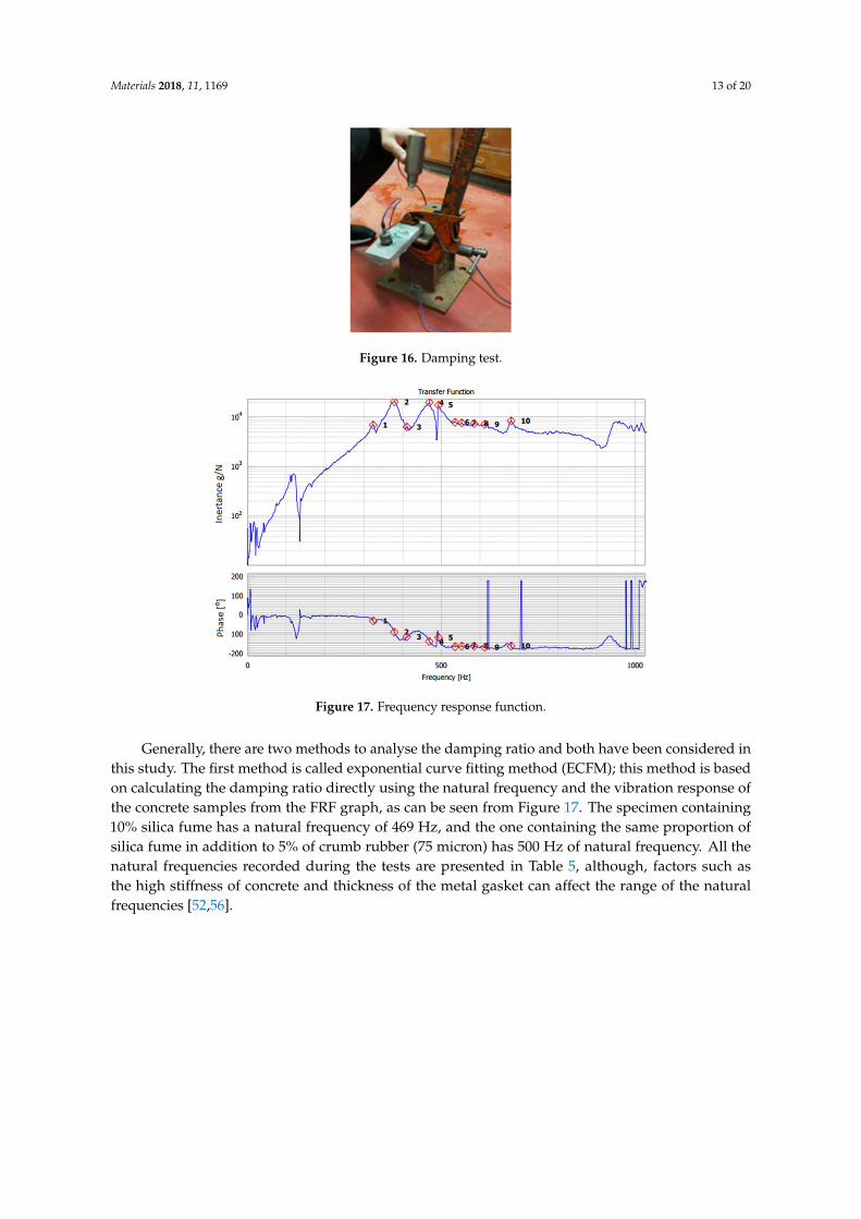
Figure 17. Frequency response function.
Generally, there are two methods to analyse the damping ratio and both have been considered in this study. The first method is called exponential curve fitting method (ECFM); this method is based on calculating the damping ratio directly using the natural frequency and the vibration response of the concrete samples from the FRF graph, as can be seen from Figure 17. The specimen containing 10% silica fume has a natural frequency of 469 Hz, and the one containing the same proportion of silica fume in addition to 5% of crumb rubber (75 micron) has 500 Hz of natural frequency. All the natural frequencies recorded during the tests are presented in Table 5, although, factors such as the high stiffness of concrete and thickness of the metal gasket can affect the range of the natural frequencies [52,56].
Table 5. Types of moulds and corresponding tests.
No. Mixes Natural Frequency (Hz)
S.D. Sample 1 Sample 2 Sample 3 Average
1 RFC 478 451 486 471.67 ±18.34 2 SF/10% 469 427 433 443 ±22.716 3 SF/5% 457 437 462 452 ±13.23 4 SF/5%–5%/CR (400&180) 476 452 463 463.67 ±12.01 5 SF/10%–5%/CR (400&180) 456 439 454 449.67 ±9.29 6 SF/5%–10%/CR (400&180) 479 493 474 482 ±9.85 7 SF/10%–10%/CR (400&180) 441 446 435 440.67 ±5.51 8 SF/5%–5%/CR (75) 443 462 431 445 ±15.63 9 SF/10%–5%/CR (75) 477 500 459 477 ±20.55
Figure 16. Damping test.
Materials 2018, 11, x FOR PEER REVIEW 13 of 20
Figure 16. Damping test.
Figure 17. Frequency response function.
Generally, there are two methods to analyse the damping ratio and both have been considered in this study. The first method is called exponential curve fitting method (ECFM); this method is based on calculating the damping ratio directly using the natural frequency and the vibration response of the concrete samples from the FRF graph, as can be seen from Figure 17. The specimen containing 10% silica fume has a natural frequency of 469 Hz, and the one containing the same proportion of silica fume in addition to 5% of crumb rubber (75 micron) has 500 Hz of natural frequency. All the natural frequencies recorded during the tests are presented in Table 5, although, factors such as the high stiffness of concrete and thickness of the metal gasket can affect the range of the natural frequencies [52,56].
Table 5. Types of moulds and corresponding tests.
No. Mixes Natural Frequency (Hz)
S.D. Sample 1 Sample 2 Sample 3 Average
1 RFC 478 451 486 471.67 ±18.34 2 SF/10% 469 427 433 443 ±22.716 3 SF/5% 457 437 462 452 ±13.23 4 SF/5%–5%/CR (400&180) 476 452 463 463.67 ±12.01 5 SF/10%–5%/CR (400&180) 456 439 454 449.67 ±9.29 6 SF/5%–10%/CR (400&180) 479 493 474 482 ±9.85 7 SF/10%–10%/CR (400&180) 441 446 435 440.67 ±5.51 8 SF/5%–5%/CR (75) 443 462 431 445 ±15.63 9 SF/10%–5%/CR (75) 477 500 459 477 ±20.55
Figure 17. Frequency response function.
Generally, there are two methods to analyse the damping ratio and both have been considered inthis study. The first method is called exponential curve fitting method (ECFM); this method is basedon calculating the damping ratio directly using the natural frequency and the vibration response ofthe concrete samples from the FRF graph, as can be seen from Figure 17. The specimen containing10% silica fume has a natural frequency of 469 Hz, and the one containing the same proportion ofsilica fume in addition to 5% of crumb rubber (75 micron) has 500 Hz of natural frequency. All thenatural frequencies recorded during the tests are presented in Table 5, although, factors such asthe high stiffness of concrete and thickness of the metal gasket can affect the range of the naturalfrequencies [52,56].

Materials 2018, 11, 1169 14 of 20
Table 5. Types of moulds and corresponding tests.
No. MixesNatural Frequency (Hz)
S.D.Sample 1 Sample 2 Sample 3 Average
1 RFC 478 451 486 471.67 ±18.342 SF/10% 469 427 433 443 ±22.7163 SF/5% 457 437 462 452 ±13.234 SF/5%–5%/CR (400&180) 476 452 463 463.67 ±12.015 SF/10%–5%/CR (400&180) 456 439 454 449.67 ±9.296 SF/5%–10%/CR (400&180) 479 493 474 482 ±9.857 SF/10%–10%/CR (400&180) 441 446 435 440.67 ±5.518 SF/5%–5%/CR (75) 443 462 431 445 ±15.639 SF/10%–5%/CR (75) 477 500 459 477 ±20.55
10 SF/5%–10%/CR (75) 453 456 472 460 ±10.2111 SF/10%–10%/CR (75) 488 493 512 498 ±12.66
The acceleration-time graph is then plotted and the exponential line is fitted with the peakamplitude according to the decreasing trend of the vibration response, while the equation of theexponential line is generated from the Microsoft Excel program as illustrated in Figure 18.
Materials 2018, 11, x FOR PEER REVIEW 14 of 20
10 SF/5%–10%/CR (75) 453 456 472 460 ±10.21 11 SF/10%–10%/CR (75) 488 493 512 498 ±12.66
The acceleration-time graph is then plotted and the exponential line is fitted with the peak amplitude according to the decreasing trend of the vibration response, while the equation of the exponential line is generated from the Microsoft Excel program as illustrated in Figure 18.
Figure 18. Vibration response of the concrete.
Finally, the equation obtained from the vibration graph (Figure 19) is compared with the reduced general mathematical equation representing the amplitude (Equation (4)), and the damping ratio is obtained as follows:
퐴 = 퐴 .푒 . . (6)
where At is the amplitude, A0 is the peak amplitude, ζ is the damping ratio, wn is the natural frequency (rad/s) equal to 2 πfn where fn is the natural frequency in Hz, and t is the time in seconds. The calculation of the damping ratio of the SF5%–CR10% sample presented by the graph of Figure 19 has led to 0.0324, which is 3.24% of critical damping ratio.
The second method is used to verify the value obtained from the ECFM and in order to make sure that the tests’ results are more reliable. It is called the logarithmic decrement method (LDM), and the damping ratio in this case is calculated using the logarithmic decrement formulas (Equations (5) and (6)):
훿 =1푛 푙푛
퐴퐴 푖푓푛 = 1,2,3… (7)
휁 =1
1 + (2휋훿 )≈
훿2휋
(8)
where δ is the damping index, A0 is the peak amplitude, An is the amplitude after n number of cycles, and ζ is the damping ratio.
The damping ratio estimated from the LDM for the same sample tested before using the ECFM is 0.0323 (3.23%), which presents a small error of 0.31%. The results regarding all the samples are plotted in the graph of Figure 20. The graph shows that the two methods have similar trend. The reference concrete has the lowest damping ratio with 0.02239 and 0.02098 respectively according to the ECFM and LDM methods. The addition of 10% silica fume improved slightly the concrete’s damping ratio to reach 0.02822 using ECFM and 0.2791 using LDM, and a little more improvement of 19 and 21% respectively when 10% of 75 micron rubber has been added. This improvement is due to the large interface area between the cement matrix and silica fume particles which offer better
Figure 18. Vibration response of the concrete.
Finally, the equation obtained from the vibration graph (Figure 19) is compared with the reducedgeneral mathematical equation representing the amplitude (Equation (4)), and the damping ratio isobtained as follows:
At = A0·e−ζ·wn ·t (6)
where At is the amplitude, A0 is the peak amplitude, ζ is the damping ratio, wn is the naturalfrequency (rad/s) equal to 2 πfn where fn is the natural frequency in Hz, and t is the time in seconds.The calculation of the damping ratio of the SF5%–CR10% sample presented by the graph of Figure 19has led to 0.0324, which is 3.24% of critical damping ratio.
The second method is used to verify the value obtained from the ECFM and in order tomake sure that the tests’ results are more reliable. It is called the logarithmic decrement method(LDM), and the damping ratio in this case is calculated using the logarithmic decrement formulas(Equations (5) and (6)):
δ =1n
lnA0
Ani f n = 1, 2, 3 . . . (7)
ζ =1√
1 +( 2π
δ
)2≈ δ
2π(8)

Materials 2018, 11, 1169 15 of 20
where δ is the damping index, A0 is the peak amplitude, An is the amplitude after n number of cycles,and ζ is the damping ratio.
The damping ratio estimated from the LDM for the same sample tested before using the ECFM is0.0323 (3.23%), which presents a small error of 0.31%. The results regarding all the samples are plottedin the graph of Figure 20. The graph shows that the two methods have similar trend. The referenceconcrete has the lowest damping ratio with 0.02239 and 0.02098 respectively according to the ECFMand LDM methods. The addition of 10% silica fume improved slightly the concrete’s damping ratioto reach 0.02822 using ECFM and 0.2791 using LDM, and a little more improvement of 19 and 21%respectively when 10% of 75 micron rubber has been added. This improvement is due to the largeinterface area between the cement matrix and silica fume particles which offer better vibration energydissipation [57,58]. Finally, the 180&400 micron rubber have proved to have the best effect on thedamping ratio of concrete, by reaching the maximum values obtained in this test: 0.04499 using ECFMand 0.04451 using LDM, which present an improvement of 100 and 112% respectively comparing tothe conventional concrete. These results confirm the theory stating that the damping ratio of concreteimproves with the increase in the size and the amount of rubber content as declared by Zheng at al. [52].A damping ratio of 3% could easily reduce up to 20–30% of dynamic actions (bending, shear, andforce); however, in order to suppress large-amplitude vibrations the damping coefficient should bearound 4–5% [57]. Consequently, since the static and dynamic properties of the rubberised concrete(180&400 micron) meet the design standards, it should highly be recommended for concrete railwaysleepers’ manufacturing [53,57].
Materials 2018, 11, x FOR PEER REVIEW 15 of 20
vibration energy dissipation [57,58]. Finally, the 180&400 micron rubber have proved to have the best effect on the damping ratio of concrete, by reaching the maximum values obtained in this test: 0.04499 using ECFM and 0.04451 using LDM, which present an improvement of 100 and 112% respectively comparing to the conventional concrete. These results confirm the theory stating that the damping ratio of concrete improves with the increase in the size and the amount of rubber content as declared by Zheng at al. [52]. A damping ratio of 3% could easily reduce up to 20–30% of dynamic actions (bending, shear, and force); however, in order to suppress large-amplitude vibrations the damping coefficient should be around 4–5% [57]. Consequently, since the static and dynamic properties of the rubberised concrete (180&400 micron) meet the design standards, it should highly be recommended for concrete railway sleepers’ manufacturing [53,57].
Figure 19. Curve fitting of vibration response of the concrete (75 µm crumb rubber).
Figure 20. Dynamic damping of crumb rubber concrete at 28 days.
5.5. Dynamic Flexural Moduli
According to Kaewunruen et al., the dynamic flexural modulus of elasticity demonstrates the elastic behaviour of material under flexural loading. The dynamic flexural modulus can be estimated from Equation (9) [49,59–61]. Figure 21 reveals that the early age dynamic moduli at 7 days of the rubberized concrete are decreased compared to the reference concrete (from 7% to 28%, depending on the mixes). This implies that the release of prestressing force on concrete sleepers should be gentle to minimise the effect on initial deformations (i.e., pre-camber and elastic shortening). Figure 22 shows the dynamic moduli of the concrete at 28 days. It can be observed that the use of silica fume can increase the dynamic moduli at 28 days. The deviation of dynamic moduli of the rubberized
00.005
0.010.015
0.020.025
0.030.035
0.040.045
0.05
Dam
ping
ratio
ECFM
LDM
Figure 19. Curve fitting of vibration response of the concrete (75 µm crumb rubber).
Materials 2018, 11, x FOR PEER REVIEW 15 of 20
vibration energy dissipation [57,58]. Finally, the 180&400 micron rubber have proved to have the best effect on the damping ratio of concrete, by reaching the maximum values obtained in this test: 0.04499 using ECFM and 0.04451 using LDM, which present an improvement of 100 and 112% respectively comparing to the conventional concrete. These results confirm the theory stating that the damping ratio of concrete improves with the increase in the size and the amount of rubber content as declared by Zheng at al. [52]. A damping ratio of 3% could easily reduce up to 20–30% of dynamic actions (bending, shear, and force); however, in order to suppress large-amplitude vibrations the damping coefficient should be around 4–5% [57]. Consequently, since the static and dynamic properties of the rubberised concrete (180&400 micron) meet the design standards, it should highly be recommended for concrete railway sleepers’ manufacturing [53,57].
Figure 19. Curve fitting of vibration response of the concrete (75 µm crumb rubber).
Figure 20. Dynamic damping of crumb rubber concrete at 28 days.
5.5. Dynamic Flexural Moduli
According to Kaewunruen et al., the dynamic flexural modulus of elasticity demonstrates the elastic behaviour of material under flexural loading. The dynamic flexural modulus can be estimated from Equation (9) [49,59–61]. Figure 21 reveals that the early age dynamic moduli at 7 days of the rubberized concrete are decreased compared to the reference concrete (from 7% to 28%, depending on the mixes). This implies that the release of prestressing force on concrete sleepers should be gentle to minimise the effect on initial deformations (i.e., pre-camber and elastic shortening). Figure 22 shows the dynamic moduli of the concrete at 28 days. It can be observed that the use of silica fume can increase the dynamic moduli at 28 days. The deviation of dynamic moduli of the rubberized
00.005
0.010.015
0.020.025
0.030.035
0.040.045
0.05
Dam
ping
ratio
ECFM
LDM
Figure 20. Dynamic damping of crumb rubber concrete at 28 days.

Materials 2018, 11, 1169 16 of 20
5.5. Dynamic Flexural Moduli
According to Kaewunruen et al., the dynamic flexural modulus of elasticity demonstrates theelastic behaviour of material under flexural loading. The dynamic flexural modulus can be estimatedfrom Equation (9) [49,59–61]. Figure 21 reveals that the early age dynamic moduli at 7 days of therubberized concrete are decreased compared to the reference concrete (from 7% to 28%, depending onthe mixes). This implies that the release of prestressing force on concrete sleepers should be gentle tominimise the effect on initial deformations (i.e., pre-camber and elastic shortening). Figure 22 showsthe dynamic moduli of the concrete at 28 days. It can be observed that the use of silica fume canincrease the dynamic moduli at 28 days. The deviation of dynamic moduli of the rubberized concreteis from 5% to 26% compared to the reference concrete. Comparatively, it is found that, at 28 days,the dynamic flexural behavior could be expected to be similar to traditional high-strength concrete(reference). This implies that the difference in creep and shrinkage would be minimal to normalconcrete sleepers. These requirements are critical for concrete sleepers in ballasted railway tracks.However, the application of this rubberised concrete can be applied to concrete slabs in ballastlesstracks of which its requirement is slightly less stringent [59–63].
Ed = 0.021ρ1.5√
fc (9)
Materials 2018, 11, x FOR PEER REVIEW 16 of 20
concrete is from 5% to 26% compared to the reference concrete. Comparatively, it is found that, at 28 days, the dynamic flexural behavior could be expected to be similar to traditional high-strength concrete (reference). This implies that the difference in creep and shrinkage would be minimal to normal concrete sleepers. These requirements are critical for concrete sleepers in ballasted railway tracks. However, the application of this rubberised concrete can be applied to concrete slabs in ballastless tracks of which its requirement is slightly less stringent [59–63].
퐸 = 0.021휌 . 푓 (9)
Figure 21. Early-age dynamic moduli of crumb rubber concrete at 7 days (MPa).
Figure 22. Dynamic moduli of crumb rubber concrete at 28 days (MPa).
6. Conclusions
Railway traffic environment is aggressive and the railway infrastructure has to experience heavy-haul or high-speed rail operation. Therefore, material for railway infrastructure needs to be strong, durable, resilient and tough to withstand various unexpected damage. Waste tyre is a global environmental problem which is non-biodegradability, flammability and chemical composition. Waste tyre cannot be solved as a normal method like disposal. This research study aimed to develop an environmentally friendly concrete using crumb rubber, recycled form waste rubber tyres (75 micron and 180 micro mixed with 400 micron), as micro-filler to make concrete sleepers that meet
0.0
5000.0
10000.0
15000.0
20000.0
25000.0
RFC
SFC-
5%
SFC-
10%
CRC-
5%/5
%
CRC-
5%/1
0%
CRC-
10%
/5%
CRC-
10%
/10%
SFRC
-5-4
00&
180-
5
SFRC
-10-
400&
180-
5
SFRC
-5-4
00&
180-
10
SFRC
-10-
400&
180-
… Dynamic modulus
0.0
5000.0
10000.0
15000.0
20000.0
25000.0
Dynamic modulus
Figure 21. Early-age dynamic moduli of crumb rubber concrete at 7 days (MPa).
Materials 2018, 11, x FOR PEER REVIEW 16 of 20
concrete is from 5% to 26% compared to the reference concrete. Comparatively, it is found that, at 28 days, the dynamic flexural behavior could be expected to be similar to traditional high-strength concrete (reference). This implies that the difference in creep and shrinkage would be minimal to normal concrete sleepers. These requirements are critical for concrete sleepers in ballasted railway tracks. However, the application of this rubberised concrete can be applied to concrete slabs in ballastless tracks of which its requirement is slightly less stringent [59–63].
퐸 = 0.021휌 . 푓 (9)
Figure 21. Early-age dynamic moduli of crumb rubber concrete at 7 days (MPa).
Figure 22. Dynamic moduli of crumb rubber concrete at 28 days (MPa).
6. Conclusions
Railway traffic environment is aggressive and the railway infrastructure has to experience heavy-haul or high-speed rail operation. Therefore, material for railway infrastructure needs to be strong, durable, resilient and tough to withstand various unexpected damage. Waste tyre is a global environmental problem which is non-biodegradability, flammability and chemical composition. Waste tyre cannot be solved as a normal method like disposal. This research study aimed to develop an environmentally friendly concrete using crumb rubber, recycled form waste rubber tyres (75 micron and 180 micro mixed with 400 micron), as micro-filler to make concrete sleepers that meet
0.0
5000.0
10000.0
15000.0
20000.0
25000.0
RFC
SFC-
5%
SFC-
10%
CRC-
5%/5
%
CRC-
5%/1
0%
CRC-
10%
/5%
CRC-
10%
/10%
SFRC
-5-4
00&
180-
5
SFRC
-10-
400&
180-
5
SFRC
-5-4
00&
180-
10
SFRC
-10-
400&
180-
… Dynamic modulus
0.0
5000.0
10000.0
15000.0
20000.0
25000.0
Dynamic modulus
Figure 22. Dynamic moduli of crumb rubber concrete at 28 days (MPa).

Materials 2018, 11, 1169 17 of 20
6. Conclusions
Railway traffic environment is aggressive and the railway infrastructure has to experienceheavy-haul or high-speed rail operation. Therefore, material for railway infrastructure needs tobe strong, durable, resilient and tough to withstand various unexpected damage. Waste tyre is aglobal environmental problem which is non-biodegradability, flammability and chemical composition.Waste tyre cannot be solved as a normal method like disposal. This research study aimed to developan environmentally friendly concrete using crumb rubber, recycled form waste rubber tyres (75 micronand 180 micro mixed with 400 micron), as micro-filler to make concrete sleepers that meet with therailway requirements. Although the emphasis is placed on concrete sleepers in ballasted railwaytracks, the application of this recycled concrete can also be applied to concrete slabs in ballastless tracks.Based on diverse proportions of crumb rubber and silica fume, eleven different types of concrete werecasted according to British standard. The first experiments carried out on the concrete specimenstested their compressive strength at 7 and 28 days, as it presents the most important property ofthis material. Similar to previous studies’ findings, it has been deducted that the increase in therubber content results in a drop in compressive strength. However, the rubber concrete containinga proportion of 10% silica fume and 5% crumb rubber has shown considerable results by reaching57.30 MPa and 59.20 MPa at 28 days in both rubber particle cases 75 micro and the mix of 180 and 400micro respectively, thus meeting the standard for railway sleepers manufacturing (55 MPa). Likewise,it has been observed a significant deterioration in both splitting tensile and flexural strengths whenincreasing the crumb rubber proportion in concrete. Still, the proportions that seemed to show bettersplitting tensile performance than plain concrete are the ones containing 10% silica fume: mixed with5% crumb rubber in the case of 180 and 400 micro rubber, and 10% in the case of 75 micro rubber(3.75 MPa and 3.54 MPa respectively).
On the other hand, the specimens containing a combination of 10% silica fume and whether5% of the 180&400 micro rubber or 10% 75 micro rubbers have shown acceptable flexural strengthssuperior to plain concrete by 8 and 13%: 6.19 MPa and 6.49 MPa, respectively. In terms of electricalresistivity, the concrete samples containing crumb rubber have shown the best results: 374.25 kΩ and371 kΩ for SF10%/CR10% (180&400) and SF10%/CR5% (75) respectively. Therefore, the addition ofcrumb rubber is capable of enhancing the electrical resistivity of conventional concrete up to 47%.Finally, by conducting vibration tests on rubberised concrete and using both the exponential curvefitting method (ECFM) and the logarithmic decrement method (LDM), it has been concluded that thecrumb rubber has clearly improved the concrete’s damping ratio, especially when using the 180&400micro which resulted in an improvement of 100% comparing to normal concrete. It is thereforerecommended from the results of this study to use crumb rubber in concrete as micro-filler, and moreprecisely the SF/10%–CR/5% (400&180) as it showed the best performance in all tests and meets therequirements of railway concrete sleepers. From the environmental perspective, the use of crumbrubber in concrete presents one of the best alternatives while dealing with rubber waste, as it will helpboth the environment protection and also the reduction in railway sleepers cost.
Author Contributions: Conceptualization, S.K., Y.C. and Z.X.; Methodology, S.K., Y.C. and Z.X.; Validation,D.L., Y.C. and Z.X.; Formal Analysis, D.L.; Investigation, Y.C. and Z.X.; Resources, S.K.; Writing-Original DraftPreparation, D.L., Y.C., Z.X.; Writing-Review & Editing, S.K.; Visualization, D.L.; Supervision, S.K.; FundingAcquisition, S.K.
Funding: This research was funded by the Japan Society for Promotion of Science (JSPS) grant number L15701and the APC was funded by the European Commission for H2020-MSCA-RISE Project No. 691135 “RISEN:Rail Infrastructure Systems Engineering Network”.
Acknowledgments: The first author wishes to gratefully acknowledge the Japan Society for Promotion of Science(JSPS) for his JSPS Invitation Research Fellowship (Long-term), Grant No. L15701, at Track Dynamics Laboratory,Railway Technical Research Institute and at Concrete Laboratory, the University of Tokyo, Tokyo, Japan. The JSPSfinancially supports this work as part of the research project entitled “Smart and reliable railway infrastructure”.The authors are very grateful to the European Commission for H2020-MSCA-RISE Project No. 691135 “RISEN:Rail Infrastructure Systems Engineering Network” (www.risen2rail.eu) [64]. In addition, the sponsorships and

Materials 2018, 11, 1169 18 of 20
assistance from CEMEX, Network Rail, Lehigh Technologies Inc., and RSSB (Rail Safety and Standard Board, UK)are highly appreciated.
Conflicts of Interest: The authors declare no conflict of interest.
References
1. Gourley, J.T.; Johnson, G.B. Developments in geopolymer precast concrete. In Proceedings of the Geopolymer2005 World Congress, Geopolymer Green Chemistry and Sustainable Development Solutions, Saint-Quentin,France, 29 June–1 July 2005; pp. 139–143.
2. Kaewunruen, S.; You, R.; Ishida, M. Composites for Timber-Replacement Bearers in Railway Switches andCrossings. Infrastructures 2017, 2, 13. [CrossRef]
3. Kaewunruen, S.; Wu, L.; Goto, K.; Najih, Y.M. Vulnerability of Structural Concrete to Extreme ClimateVariances. Climate 2018, 6, 40. [CrossRef]
4. FIP Commission on Prefabrication, FIP Commission on Prefabrication; Working Group on Concrete RailwaySleepers & Fédération Internationale de la Précontrainte. Working Group on Concrete Railway Sleepers. ConcreteRailway Sleepers; Thomas Telford Services Ltd.: London, UK, 1987.
5. Gupta, T.; Chaudhary, S.; Sharma, R.K. Mechanical and durability properties of waste rubber fiber concretewith and without silica fume. J. Clean. Prod. 2016, 112, 702–711. [CrossRef]
6. Aiello, M.; Leuzzi, F. Waste tyre rubberized concrete: Properties at fresh and hardened state. Waste Manag.2010, 30, 1696–1704. [CrossRef] [PubMed]
7. Thomas, B.S.; Gupta, R.C. A comprehensive review on the applications of waste tire rubber in cementconcrete. Renew. Sustain. Energy Rev. 2016, 54, 1323–1333. [CrossRef]
8. Remennikov, A.M.; Kaewunruen, S. A review of loading conditions for railway track structures due to trainand track vertical interaction. Struct. Control Health Monit. 2008, 15, 207–234. [CrossRef]
9. Silva, É.A.; Pokropski, D.; You, R.; Kaewunruen, S. Comparison of structural design methods for railwaycomposites andplastic sleepers and bearers. Aust. J. Struct. Eng. 2017, 18, 160–177. [CrossRef]
10. Kaewunruen, S.; Remennikov, A.M. Progressive failure of prestressed concrete sleepers under multiplehigh-intensity impact loads. Eng. Struct. 2009, 31, 2460–2473. [CrossRef]
11. Cai, H.Q. Structure analysis of railway. J. Hebei Inst. Arch. 2006, 29, 18–20.12. Kaewunruen, S.; Remennikov, A.M. Influence of voids and pockets on the vibration characteristics of
prestressed concrete sleepers. In Proceedings of the Society of Experimental Mechanics (SEM) AnnualConference and Exhibition, Orlando, FL, USA, 19–22 February 2007; pp. 3–6.
13. Esveld, C. Modern Railway Track, 2nd ed.; MRT-Productions: Delft, The Netherlands, 2001; ISBN 90-800324-3-3.14. Indraratna, B.; Rujikiatkamjorn, C.; Salim, W. Advanced Rail Geotechnology–Ballasted Track; CRC Press: London,
UK, 2011.15. Remennikov, A.M.; Kaewunruen, S. Resistance of railway concrete sleepers to impact loading. In Proceedings of
the 7th International Conference on Shock & Impact Loads on Structures, Beijing, China, 17–19 October 2007;pp. 489–496.
16. You, R.; Li, D.; Ngamkhanong, C.; Janeliukstis, R.; Kaewunruen, S. Fatigue Life Assessment Method forPrestressed Concrete Sleepers. Front. Built Environ. 2017, 3, 68. [CrossRef]
17. Zhang, X.; Thompson, D.J.; Squicciarini, G. Sound radiation from railway sleepers. J. Sound Vib. 2016, 369,178–194. [CrossRef]
18. Hameed, A.S.; Shashikala, A. Suitability of rubber concrete for railway sleepers. Perspect. Sci. 2016, 8, 32–35.[CrossRef]
19. Salam, H.E.; Sherbini, A.S.; Seleem, M.H.; Balaha, M.M. Impact Resistance of Rubberized Concrete.Eng. Res. J. 2008, 31, 265–271.
20. Topçu, I.B.; Demir, A. Durability of Rubberized Mortar and Concrete. J. Mater. Civ. Eng. 2007, 19, 173–178.[CrossRef]
21. Topçu, I.B.; Sengel, S. Properties of concretes produced with waste concrete aggregate. Cem. Concr. Res. 2004,34, 1307–1312. [CrossRef]
22. Anagennisi Project. Rubberised Concrete. 2017. Available online: http://anagennisi.org/wordpress/portfolio/rubberised-concrete-optimised-mix (accessed on 14 February 2018).

Materials 2018, 11, 1169 19 of 20
23. Sol-Sánchez, M.; Thom, N.; Moreno-Navarro, F.; Rubio-Gámez, M.; Airey, G. A study into the use of crumbrubber in railway ballast. Constr. Build. Mater. 2015, 75, 19–24. [CrossRef]
24. Toutanji, H. The use of rubber tire particles in concrete to replace mineral aggregates. Cem. Concr. Compos.1996, 18, 135–139. [CrossRef]
25. Khaloo, A.R.; Dehestani, M.; Rahmatabadi, P. Mechanical properties of concrete containing a high volume oftire–rubber particles. Waste Manag. 2008, 28, 2472–2482. [CrossRef] [PubMed]
26. Ganjian, E.; Khorami, M.; Maghsoudi, A.A. Scrap-tyre-rubber replacement for aggregate and filler in concrete.Constr. Build. Mater. 2009, 23, 1828–1836. [CrossRef]
27. Paine, K.A.; Dhir, R.K.; Moroney, R.; Kopasakis, K. Use of Crumb Rubber to Achieve Freeze/Thaw ResistingConcrete. In Proceedings of the International Conference on Concrete for Extreme Conditions, Dundee, UK,9–11 September 2002; pp. 485–498. [CrossRef]
28. Hernández-Olivares, F.; Barluenga, G. Fire performance of recycled rubber-filled high-strength concrete.Cem. Concr. Res. 2004, 34, 109–117. [CrossRef]
29. Fattuhi, N.; Clark, L. Cement-based materials containing shredded scrap truck tyre rubber. Constr. Build. Mater.1996, 10, 229–236. [CrossRef]
30. Van Dyk, B.J.; Edwards, J.R.; Dersch, M.S.; Ruppert, C.J., Jr.; Barkan, C.P.L. Evaluation of dynamic and impactwheel load factors and their application in design processes. Proc. Inst. Mech. Eng. Part F 2017, 231, 33–43.[CrossRef]
31. Kaewunruen, S.; Remennikov, A.M. Sensitivity analysis of free vibration characteristics of an in situ railwayconcrete sleeper to variations of rail pad parameters. J. Sound Vib. 2006, 298, 453–461. [CrossRef]
32. BS EN 13230 Concrete Sleepers and Bearers; British Standards Institute: London, UK, 2016.33. BS EN 934-2 Admixtures for Concrete, Mortar and Grout; British Standards Institute: London, UK, 2009.34. Mazloom, M.; Ramezanianpour, A.; Brooks, J. Effect of silica fume on mechanical properties of high-strength
concrete. Cem. Concr. Compos. 2004, 26, 347–357. [CrossRef]35. Elkem-Microsilica Grade 940 for Construction. 2017. Available online: https://www.elkem.com/silicon-
materials/high-performance-concrete/microsilica-concrete-grades/microsilica-grade-940-construction/(accessed on 14 February 2018).
36. BS EN 12620 Aggregates for Concrete; British Standards Institute: London, UK, 2013.37. BS EN 206-1 Concrete: Part 1—Specification, Performance, Production and Conformity; British Standards Institute:
London, UK, 2000.38. Mirza, O.; Kaewunruen, S. Influence of shear bolt connections on modular precast steel-concrete composites
for track support structures. Steel Comp. Struct. 2018, 27, 647–659.39. BS EN 13139 Aggregates for Mortar; British Standards Institute: London, UK, 2013.40. BS EN 12390-3 Testing Hardened Concrete: Part 3: Compressive Strength of Test Specimens; British Standards
Institute: London, UK, 2009.41. Sukontasukkul, P.; Chaikaew, C. Properties of concrete pedestrian block mixed with crumb rubber.
Constr. Build. Mater. 2006, 20, 450–457. [CrossRef]42. Atahan, A.O.; Yücel, A.Ö. Crumb rubber in concrete: Static and dynamic evaluation. Constr. Build. Mater.
2012, 36, 617–622. [CrossRef]43. He, L.; Ma, Y.; Liu, Q.; Mu, Y. Surface modification of crumb rubber and its influence on the mechanical
properties of rubber-cement concrete. Constr. Build. Mater. 2016, 120, 403–407. [CrossRef]44. Su, H.; Yang, J.; Ling, T.; Ghataora, G.S.; Dirar, S. Properties of concrete prepared with waste tyre rubber
particles of uniform and varying sizes. J. Clean. Prod. 2015, 91, 288–296. [CrossRef]45. BS EN 12390-6 Testing Hardened Concrete: Part 6: Tensile Splitting Strength of Test Specimens; British Standards
Institute: London, UK, 2009.46. BS EN 12390-5 Testing Hardened Concrete: Part 5: Flexural Strength of Test Specimens; British Standards Institute:
London, UK, 2009.47. Xiao, J.; Li, W.; Fan, Y.; Huang, X. An overview of study on recycled aggregate concrete in China (1996–2011).
Constr. Build. Mater. 2012, 31, 364–383. [CrossRef]48. Çakır, Ö. Experimental analysis of properties of recycled coarse aggregate (RCA) concrete with mineral
additives. Constr. Build. Mater. 2014, 68, 17–25. [CrossRef]49. Kaewunruen, S.; Meesit, R.; Mondal, P. Early age dynamic moduli of crumbed rubber concrete for compliant
railway structures. J. Sustain. Cem.-Based Mater. 2017, 6, 281–292. [CrossRef]

Materials 2018, 11, 1169 20 of 20
50. New York State Assembly. NYS Assembly Priority for Waste Tire Cleanups Finally a Reality. 2003.Available online: http://assembly.state.ny.us/comm/SolidWaste/20030714 (accessed on 14 February 2018).
51. Remennikov, A.M.; Kaewunruen, S. Experimental load rating of aged railway concrete sleepers. Eng. Struct.2014, 76, 147–162. [CrossRef]
52. Zheng, L.; Sharon Huo, X.; Yuan, Y. Experimental investigation on dynamic properties of rubberized concrete.Constr. Build. Mater. 2008, 22, 939–947. [CrossRef]
53. Kaewunruen, S.; Akono, A.-T.; Remennikov, A.M. Attenuation effect of material damping on impact vibrationresponses of railway concrete sleepers. GeoMEast 2018, accepted.
54. Kaewunruen, S.; Meesit, R. Sensitivity of crumb rubber particle sizes on electrical resistance of rubberisedconcrete. Cogent Eng. 2016, 3, 1126937. [CrossRef]
55. Meesit, R.; Kaewunruen, S. Vibration characteristics of micro-engineered crumb rubber concrete for railwaysleeper applications. J. Adv. Concr. Technol. 2017, 15, 55–66. [CrossRef]
56. Kaewunruen, S.; Remennikov, A.; Aikawa, A. A numerical study to evaluate dynamic responses of voidedconcrete railway sleepers to impact loading. In Proceedings of the Australian Acoustical Society Conference2011, Gold Coast, Australia, 2–4 November 2011; Available online: http://ro.uow.edu.au/engpapers/628/(accessed on 14 February 2018).
57. Kaewunruen, S.; Rachid, A.; Goto, K. Damping effects on vibrations of railway concrete sleepers.In Proceedings of the 3rd World Multidisciplinary Civil Engineering—Architecture—Urban PlanningSymposium, Prigue, Czech, 13–17 June 2016.
58. Xu, Y.; Chung, D. Improving silica fume cement by using silane. Cem. Concr. Res. 2000, 30, 1305–1311.[CrossRef]
59. Akono, A.-T.; Chen, J.; Kaewunruen, S. Friction and fracture characteristics of engineered crumb-rubberconcrete at microscopic lengthscale. Constr. Build. Mater. 2018, 175, 735–745. [CrossRef]
60. Kaewunruen, S.; Remennikov, A.M. Experimental simulation of the railway ballast by resilient materials andits verification by modal testing. Exp. Tech. 2008, 32, 29–35. [CrossRef]
61. Kaewunruen, S.; Remennikov, A.M. Nonlinear finite element modeling of railway prestressed concretesleeper. In Proceedings of the 10th East Asia-Pacific Conference on Structural Engineering and Construction,EASEC 2010, Bangkok, Thailand, 3–5 August 2006; Volume 4, pp. 323–328.
62. Praticò, F.G.; Giunta, M. Proposal of a Key Performance Indicator for Railway Track Based on LCC andRAMS Analyses. J. Constr. Eng. Manag. 2018, 144, 04017104. [CrossRef]
63. Zhou, Y.; Wang, K.; Lv, K. Comparison of wheel/rail dynamic responses of the rail weld zones betweenballasted track and slab track in high-speed railways. J. Adv. Veh. Eng. 2017, 3, 177–181.
64. Kaewunruen, S.; Sussman, J.M.; Matsumoto, A. Grand Challenges in Transportation and Transit Systems.Front. Built Environ. 2016, 2, 4. [CrossRef]
© 2018 by the authors. Licensee MDPI, Basel, Switzerland. This article is an open accessarticle distributed under the terms and conditions of the Creative Commons Attribution(CC BY) license (http://creativecommons.org/licenses/by/4.0/).


![1,2 ID 1 ID é ID - Semantic Scholar...leaks caused by biocorrosion in Scotland, South West England, Saudi Arabia, and USA [4]. During 2003, in Maryland, around 5200 cases of pinhole](https://img.dokumen.tips/doc/110x75/5fc6bbcbfdc2393b312095c0/12-id-1-id-id-semantic-scholar-leaks-caused-by-biocorrosion-in-scotland.jpg)