Embed Size (px)
Citation preview

INS
TRU
CTIO
NM
AN
UA
L12" Bench Drill Press
(Model DP300)
ESPAÑOL: PÁGINA 17
PART NO. 905575-04-29-04Copyright © 2004 Delta Machinery
To learn more about DELTA MACHINERY visit our website at: www.deltamachinery.com.For Parts, Service, Warranty or other Assistance,
please call 1-800-223-7278 (In Canada call 1-800-463-3582).
62061
RTD10000126AA

2
Indicates an imminently hazardous situation which, if not avoided, will result in death or serious injury.
Indicates a potentially hazardous situation which, if not avoided, could result in death or serious injury.
Indicates a potentially hazardous situation which, if not avoided, may result in minor or moderate injury.
Used without the safety alert symbol indicates potentially hazardous situation which, if not avoided, mayresult in property damage.
This manual contains information that is important for you to know and understand. This information relates to protect-ing YOUR SAFETY and PREVENTING EQUIPMENT PROBLEMS. To help you recognize this information, we use thesymbols below. Please read the manual and pay attention to these sections.
SAFETY GUIDELINES - DEFINITIONS
SOME DUST CREATED BY POWER SANDING, SAWING, GRINDING, DRILLING, AND OTHERCONSTRUCTION ACTIVITIES contains chemicals known to cause cancer, birth defects or other reproductive harm.Some examples of these chemicals are:· lead from lead-based paints,· crystalline silica from bricks and cement and other masonry products, and· arsenic and chromium from chemically-treated lumber. Your risk from these exposures varies, depending on how often you do this type of work. To reduce your exposure tothese chemicals: work in a well ventilated area, and work with approved safety equipment, always wear MSHA/NIOSHapproved, properly fitting face mask or respirator when using such tools.
GENERAL SAFETY RULES
READ AND UNDERSTAND ALL WARNINGS AND OPERATING INSTRUCTIONS BEFOREUSING THIS EQUIPMENT. Failure to follow all instructions listed below, may result in electric shock,fire, and/or serious personal injury or property damage.
IMPORTANT SAFETY INSTRUCTIONS
Woodworking can be dangerous if safe and proper operating procedures are not followed. As with all machinery, thereare certain hazards involved with the operation of the product. Using the machine with respect and caution willconsiderably lessen the possibility of personal injury. However, if normal safety precautions are overlooked or ignored,personal injury to the operator may result. Safety equipment such as guards, push sticks, hold-downs, featherboards,goggles, dust masks and hearing protection can reduce your potential for injury. But even the best guard won’t makeup for poor judgment, carelessness or inattention. Always use common sense and exercise caution in the workshop.If a procedure feels dangerous, don’t try it. Figure out an alternative procedure that feels safer. REMEMBER: Yourpersonal safety is your responsibility. For additional information please visit our website www.deltamachinery.com.
This machine was designed for certain applications only. Delta Machinery strongly recommends that thismachine not be modified and/or used for any application other than that for which it was designed. If you have anyquestions relative to a particular application, DO NOT use the machine until you have first contacted Delta to determineif it can or should be performed on the product.
Technical Service ManagerDelta Machinery4825 Highway 45 NorthJackson, TN 38305
(IN CANADA: 505 SOUTHGATE DRIVE, GUELPH, ONTARIO N1H 6M7)

3
GENERAL SAFETY RULES
1. FOR YOUR OWN SAFETY, READ THE INSTRUCTIONMANUAL BEFORE OPERATING THE MACHINE.Learning the machine’s application, limitations, andspecific hazards will greatly minimize the possibility ofaccidents and injury.
2. WEAR EYE PROTECTION. ALWAYS USE SAFETYGLASSES. Also use face or dust mask if cuttingoperation is dusty. Everyday eyeglasses are NOT safetyglasses. USE CERTIFIED SAFETY EQUIPMENT. Eyeprotection equipment should comply with ANSI Z87.1standards, hearing equipment should comply withANSI S3.19 standards, and dust mask protectionshould comply with MSHA/NIOSH certified respiratorstandards. Splinters, air-borne debris, and dust cancause irritation, injury, and/or illness.
3. WEAR PROPER APPAREL. Do not wear looseclothing, gloves, neckties, rings, bracelets, or otherjewelry which may get caught in moving parts. Nonslipfootwear is recommended. Wear protective haircovering to contain long hair.
4. DO NOT USE THE MACHINE IN A DANGEROUSENVIRONMENT. The use of power tools in damp orwet locations or in rain can cause shock orelectrocution. Keep your work area well-lit to preventtripping or placing arms, hands, and fingers in danger.
5. MAINTAIN ALL TOOLS AND MACHINES IN PEAKCONDITION. Keep tools sharp and clean for best and safestperformance. Follow instructions for lubricating and changingaccessories. Poorly maintained tools and machines can furtherdamage the tool or machine and/or cause injury.
6. CHECK FOR DAMAGED PARTS. Before using themachine, check for any damaged parts. Check foralignment of moving parts, binding of moving parts,breakage of parts, and any other conditions that mayaffect its operation. A guard or any other part that isdamaged should be properly repaired or replaced.Damaged parts can cause further damage to themachine and/or injury.
7. KEEP THE WORK AREA CLEAN. Cluttered areas andbenches invite accidents.
8. KEEP CHILDREN AND VISITORS AWAY. Your shop is apotentially dangerous environment. Children and visitors canbe injured.
9. REDUCE THE RISK OF UNINTENTIONAL STARTING.Make sure that the switch is in the “OFF” positionbefore plugging in the power cord. In the event of apower failure, move the switch to the “OFF” position.An accidental start-up can cause injury.
10. USE THE GUARDS. Check to see that all guards are inplace, secured, and working correctly to prevent injury.
11. REMOVE ADJUSTING KEYS AND WRENCHESBEFORE STARTING THE MACHINE. Tools, scrappieces, and other debris can be thrown at high speed,causing injury.
12. USE THE RIGHT MACHINE. Don’t force a machine oran attachment to do a job for which it was notdesigned. Damage to the machine and/or injury mayresult.
13. USE RECOMMENDED ACCESSORIES. The use ofaccessories and attachments not recommended byDelta may cause damage to the machine or injury to theuser.
14. USE THE PROPER EXTENSION CORD. Make sureyour extension cord is in good condition. When usingan extension cord, be sure to use one heavy enough tocarry the current your product will draw. An undersizedcord will cause a drop in line voltage, resulting in loss ofpower and overheating. See the Extension Cord Chartfor the correct size depending on the cord length andnameplate ampere rating. If in doubt, use the nextheavier gauge. The smaller the gauge number, theheavier the cord.
15. SECURE THE WORKPIECE. Use clamps or a vise to holdthe workpiece when practical. Loss of control of aworkpiece can cause injury.
16. FEED THE WORKPIECE AGAINST THE DIRECTION OFTHE ROTATION OF THE BLADE, CUTTER, OR ABRASIVESURFACE. Feeding it from the other direction will causethe workpiece to be thrown out at high speed.
17. DON’T FORCE THE WORKPIECE ON THE MACHINE.Damage to the machine and/or injury may result.
18. DON’T OVERREACH. Loss of balance can make youfall into a working machine, causing injury.
19. NEVER STAND ON THE MACHINE. Injury could occur if thetool tips, or if you accidentally contact the cutting tool.
20. NEVER LEAVE THE MACHINE RUNNING UNATTENDED.TURN THE POWER OFF. Don’t leave the machine until itcomes to a complete stop. A child or visitor could be injured.
21. TURN THE MACHINE “OFF”, AND DISCONNECT THEMACHINE FROM THE POWER SOURCE before installingor removing accessories, before adjusting or changingset-ups, or when making repairs. An accidental start-upcan cause injury.
22. MAKE YOUR WORKSHOP CHILDPROOF WITHPADLOCKS, MASTER SWITCHES, OR BYREMOVING STARTER KEYS. The accidental start-upof a machine by a child or visitor could cause injury.
23. STAY ALERT, WATCH WHAT YOU ARE DOING, ANDUSE COMMON SENSE. DO NOT USE THEMACHINE WHEN YOU ARE TIRED OR UNDER THEINFLUENCE OF DRUGS, ALCOHOL, OR MEDICA-TION. A moment of inattention while operating powertools may result in injury.
24. TAKE PRECAUTIONS AGAINST DUST INHALATION.The dust generated by certain woods and woodproducts can be injurious to your health. Alwaysoperate machinery in well-ventilated areas, and providefor proper dust removal. Use wood dust collectionsystems whenever possible.
FAILURE TO FOLLOW THESE RULES MAY RESULT IN SERIOUS INJURY.

4
ADDITIONAL SAFETY RULES FOR
FOR DRILL PRESSES
1. DO NOT OPERATE THIS MACHINE until it iscompletely assembled and installed according tothe instructions. A machine incorrectly assembled cancause serious injury.
2. OBTAIN ADVICE from your supervisor, instructor,or another qualified person if you are notthoroughly familiar with the operation of thismachine. Knowledge is safety.
3. FOLLOW ALL WIRING CODES and recommendedelectrical connections to prevent shock or electrocution.
4. SECURE THE MACHINE TO A SUPPORTING SUR-FACE. Vibration can cause the machine to slide, walk,or tip over.
5. NEVER START THE MACHINE BEFORECLEARING THE TABLE OF ALL OBJECTS (tools,scrap pieces, etc.). Debris can be thrown at highspeed.
6. NEVER START THE MACHINE with the drill bit,cutting tool, or sanding drum against theworkpiece. Loss of control of the workpiece cancause serious injury.
7. PROPERLY LOCK THE DRILL BIT, CUTTING TOOL,OR SANDING DRUM IN THE CHUCK beforeoperating this machine.
8. REMOVE THE CHUCK KEY BEFORE STARTINGTHE MACHINE. The chuck key can be thrown outat a high speed.
9. TIGHTEN ALL LOCK HANDLES before starting themachine. Loss of control of the workpiece cancause serious injury.
10. USE ONLY DRILL BITS, CUTTING TOOLS,SANDING DRUMS, OR OTHER ACCESSORIESwith shank size recommended in your instructionmanual. The wrong size accessory can causedamage to the machine and/or serious injury.
11. USE ONLY DRILL BITS, CUTTING TOOLS, ORSANDING DRUMS that are not damaged.Damaged items can cause malfunctions that leadto injuries.
12. USE RECOMMENDED SPEEDS for all operations.Other speeds may cause the machine tomalfunction causing damage to the machineand/or serious injury.
13. AVOID AWKWARD OPERATIONS AND HANDPOSITIONS. A sudden slip could cause a hand tomove into the bit.
14. KEEP ARMS, HANDS, AND FINGERS away fromthe bit. Serious injury to the hand can occur.
15. HOLD THE WORKPIECE FIRMLY AGAINST THETABLE. Do not attempt to drill a workpiece thatdoes not have a flat surface against the table, orthat is not secured by a vise. Prevent theworkpiece from rotating by clamping it to the tableor by securing it against the drill press column.Loss of control of the workpiece can cause seriousinjury.
16. TURN THE MACHINE “OFF” AND WAIT FOR THEDRILL BIT, CUTTING TOOL, OR SANDING DRUMTO STOP TURNING prior to cleaning the work area,removing debris, removing or securing work-piece,or changing the angle of the table. A moving drillbit, cutting tool, or sanding drum can causeserious injury.
17. PROPERLY SUPPORT LONG OR WIDE work-pieces. Loss of control of the workpiece can causesevere injury.
18. NEVER PERFORM LAYOUT, ASSEMBLY ORSET-UP WORK on the table/work area when themachine is running. Serious injury can result.
19. TURN THE MACHINE “OFF”, disconnect themachine from the power source, and clean thetable/work area before leaving the machine. LOCKTHE SWITCH IN THE “OFF” POSITION toprevent unauthorized use. Someone else mightaccidentally start the machine and cause seriousinjury to themselves.
20. ADDITIONAL INFORMATION regarding the safeand proper operation of power tools (i.e. a safetyvideo) is available from the Power Tool Institute,1300 Sumner Avenue, Cleveland, OH 44115-2851(www.powertoolinstitute.com). Information is alsoavailable from the National Safety Council, 1121Spring Lake Drive, Itasca, IL 60143-3201. Pleaserefer to the American National Standards InstituteANSI 01.1 Safety Requirements for WoodworkingMachines and the U.S. Department of Labor OSHA1910.213 Regulations.
SAVE THESE INSTRUCTIONS.Refer to them often
and use them to instruct others.
FAILURE TO FOLLOW THESE RULES MAY RESULT IN SERIOUS INJURY.

5
A separate electrical circuit should be used for your machines. This circuit should not be less than #12 wire and shouldbe protected with a 20 Amp time lag fuse. If an extension cord is used, use only 3-wire extension cords which have 3-prong grounding type plugs and matching receptacle which will accept the machine’s plug. Before connecting themachine to the power line, make sure the switch (s) is in the “OFF” position and be sure that the electric current is ofthe same characteristics as indicated on the machine. All line connections should make good contact. Running on lowvoltage will damage the machine.
DO NOT EXPOSE THE MACHINE TO RAIN OR OPERATE THE MACHINE IN DAMP LOCATIONS.
Fig. A Fig. B
GROUNDED OUTLET BOX
CURRENTCARRYING
PRONGS
GROUNDING BLADEIS LONGEST OF THE 3 BLADES
GROUNDED OUTLET BOX
GROUNDINGMEANS
ADAPTER
2. Grounded, cord-connected machines intended foruse on a supply circuit having a nominal rating lessthan 150 volts:
If the machine is intended for use on a circuit that has anoutlet that looks like the one illustrated in Fig. A, themachine will have a grounding plug that looks like the plugillustrated in Fig. A. A temporary adapter, which looks likethe adapter illustrated in Fig. B, may be used to connectthis plug to a matching 2-conductor receptacle as shownin Fig. B if a properly grounded outlet is not available. Thetemporary adapter should be used only until a properlygrounded outlet can be installed by a qualified electrician.The green-colored rigid ear, lug, and the like, extendingfrom the adapter must be connected to a permanentground such as a properly grounded outlet box. Wheneverthe adapter is used, it must be held in place with a metalscrew.
NOTE: In Canada, the use of a temporary adapter is notpermitted by the Canadian Electric Code.
In all cases, make certain that thereceptacle in question is properlygrounded. If you are not sure, have aqualified electrician check the recep-tacle.
1. All grounded, cord-connected machines:
In the event of a malfunction or breakdown, groundingprovides a path of least resistance for electric current toreduce the risk of electric shock. This machine isequipped with an electric cord having an equipment-grounding conductor and a grounding plug. The plug mustbe plugged into a matching outlet that is properly installedand grounded in accordance with all local codes andordinances.
Do not modify the plug provided - if it will not fit the outlet,have the proper outlet installed by a qualified electrician.
Improper connection of the equipment-groundingconductor can result in risk of electric shock. Theconductor with insulation having an outer surface that isgreen with or without yellow stripes is the equipment-grounding conductor. If repair or replacement of theelectric cord or plug is necessary, do not connect theequipment-grounding conductor to a live terminal.
Check with a qualified electrician or service personnel ifthe grounding inst ruct ions are not complete lyunderstood, or if in doubt as to whether the machine isproperly grounded.
Use only 3-wire extension cords that have 3-pronggrounding type plugs and matching 3-conductorreceptacles that accept the machine’s plug, as shown inFig. A.
Repair or replace damaged or worn cord immediately.
POWER CONNECTIONS
MOTOR SPECIFICATIONSYour machine is wired for 120 volt, 60 HZ alternating current. Before connecting the machine to the power source,make sure the switch is in the “OFF” position.
GROUNDING INSTRUCTIONSTHIS MACHINE MUST BE GROUNDED WHILE IN USE TO PROTECT THE OPERATOR FROMELECTRIC SHOCK.
6
EXTENSION CORDS
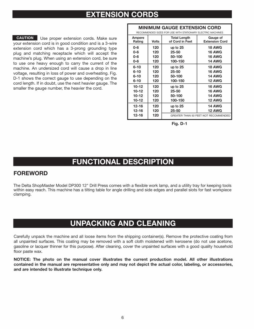
Use proper extension cords. Make sureyour extension cord is in good condition and is a 3-wireextension cord which has a 3-prong grounding typeplug and matching receptacle which will accept themachine’s plug. When using an extension cord, be sureto use one heavy enough to carry the current of themachine. An undersized cord will cause a drop in linevoltage, resulting in loss of power and overheating. Fig.D-1 shows the correct gauge to use depending on thecord length. If in doubt, use the next heavier gauge. Thesmaller the gauge number, the heavier the cord.
Fig. D-1
MINIMUM GAUGE EXTENSION CORDRECOMMENDED SIZES FOR USE WITH STATIONARY ELECTRIC MACHINES
Ampere Total Length Gauge ofRating Volts of Cord in Feet Extension Cord
0-6 120 up to 25 18 AWG0-6 120 25-50 16 AWG0-6 120 50-100 16 AWG0-6 120 100-150 14 AWG
6-10 120 up to 25 18 AWG6-10 120 25-50 16 AWG6-10 120 50-100 14 AWG6-10 120 100-150 12 AWG
10-12 120 up to 25 16 AWG10-12 120 25-50 16 AWG10-12 120 50-100 14 AWG10-12 120 100-150 12 AWG
12-16 120 up to 25 14 AWG12-16 120 25-50 12 AWG12-16 120 GREATER THAN 50 FEET NOT RECOMMENDED
FUNCTIONAL DESCRIPTIONFOREWORD
The Delta ShopMaster Model DP300 12" Drill Press comes with a flexible work lamp, and a utility tray for keeping toolswithin easy reach. This machine has a tilting table for angle drilling and side edges and parallel slots for fast workpiececlamping.
UNPACKING AND CLEANING
Carefully unpack the machine and all loose items from the shipping container(s). Remove the protective coating fromall unpainted surfaces. This coating may be removed with a soft cloth moistened with kerosene (do not use acetone,gasoline or lacquer thinner for this purpose). After cleaning, cover the unpainted surfaces with a good quality householdfloor paste wax.
NOTICE: The photo on the manual cover illustrates the current production model. All other illustrationscontained in the manual are representative only and may not depict the actual color, labeling, or accessories,and are intended to illustrate technique only.

7
14. Clamp
15. Mounting bracket
16. Tray
17. Mounting arm
1. Drill Press Head and Motor
2. Table
3. Column, Base Flange and Rack
4. Base
5. M8x1.25x25mm Hex Head Cap Screws (4)
6. Worm Gear for Table Raising and Lowering
7. Hex Wrenches (2)
8. Pinion Shaft Handles (3)
9. M8x1.25x125mm Carriage Head Screws (2), M8Flat Washers (2), M8.1 Lock Washers (2), M8x1.25Hex Nuts (2) (for fastening the base to a supportingsurface)
10. Chuck Key
11. Table Raising and Lowering Handle
12. Table Clamp
13. Chuck
1
CARTON CONTENTS
2 3
4
56789101112
13
14 15 16
17

8
1. Attach the column (A) Fig. 3 to the base (B) using the four M8x1.25x25mm hex head screws (C), three of whichare shown. Loosen the set screw (D) and remove the ring (E) and raising rack (F).
2. Place the worm gear (G) Fig. 4 in the table bracket (H).
3. Insert the raising rack (F) Fig. 6 (removed in STEP 1) in the table bracket groove (I).
NOTE: Place the teeth of the raising rack (F) in the teeth of the worm gear (G) located inside table bracket.
4. Slide the raising rack (F) Fig. 7and the table with the table bracket (J) on the drill press column (K) Fig. 7.
ASSEMBLY
For your own safety, do not connect the machine to the power source until the machine iscompletely assembled and you read and understand the entire instruction manual.
A
E
F
D
CB
Fig. 3 Fig. 4
Fig. 5
NOTE: Place the small end of the worm gear (G) Fig. 5in the hole (J), then into the hole for the worm gear. Thecorrect placement is shown in Fig. 5.
GH
G
J
Fig. 6 Fig. 7
F
G
JK
F
I

9
Fig. 8
Fig. 11 Fig. 12
5. Place the mounting bracket (A) Fig. 9 on the column.
NOTE: To avoid interference with the spindle height adjusting handles (P) Fig. 16, place the mounting bracket on theopposite side of the column from the raising rack.
6. Insert the hose clamp (B) Fig. 9 through the mounting bracket, under the raising rack, and around the column.Tighten the hose clamp securely.
7. Slide the mounting arm (C) with the tray (A) into the bracket (D) (Fig. 10).
8. Install the ring (E) Fig. 11 (removed in STEP 1) on the column.
IMPORTANT: Place the raising rack under the bottom of the ring, but allow enough clearance so that the rack (F) can rotatearound the column. Tighten the set screw (D) Fig. 11.
9. Attach the table raising and lowering handle (K) Fig. 12 on the worm gear shaft (G) and tighten the set screw (L)against the flat on the shaft.
NOTE: Place the bottom of the raising rack (F) Fig. 8inside the flange (L) on the drill press base.
F
L
Fig. 9
A
B
Fig. 10
Fig. 8
D C
A
DEG
L
K
Fig. 11 Fig. 12

10
NOTE: Make certain that the spindle taper (Q) Fig. 17 and the tapered hole in the chuck (R) are clean and free ofgrease, lacquer, or rust preventive coatings. NOTE: Household oven cleaner can effectively remove any substance from the spindle and chuck. Carefully follow themanufacturer's safety rules concerning its use.
13. Open the chuck jaws as wide as possible by turning the chuck sleeve (S) Fig. 18. Hold the chuck on the taperof the spindle and tap with a rubber mallet (T) or a block of wood and hammer to set the chuck (Fig. 18).
IMPORTANT: To avoid damage to the chuck, DO NOT drive the chuck on the spindle with a metal hammer.
O
P
10. Thread the stud of the clamp handle (M) Fig. 14 in the hole in the rear of the table bracket.11. Seat the drill press head (N) Fig. 15 on the column. Align the head (A) Fig. 15A, with the table (B) and base (C).
Tighten the two head locking screws (O) Fig. 15 with the supplied wrench.12. Thread the three pinion shaft handles (P) Fig. 16 in the three tapped holes located in the pinion shaft.
Fig. 14 Fig. 15
Fig. 15A Fig. 16
Fig. 17 Fig. 18
M
N
O
P
A
B
F
P
Q
R
ST

11
FASTENING DRILL PRESS TOSUPPORTING SURFACE
If, during operation, the machine has a tendency to tipover, slide, or walk on the supporting surface, secure themachine base to the supporting surface with anM8x1.25x125mm carriage head screw, 8.5mm flatwasher, 8.5mm lock washer, M8x1.25 hex nut throughthe two holes (A) Fig. 19 located in the machine base.
STARTING AND STOPPING THEMACHINE
The switch (A) Fig. 20 is located on the front of the drillpress head. To turn the drill press “ON”, move theswitch up. To turn the drill press “OFF”, move theswitch down.
Fig. 19
A
OPERATING CONTROLS AND ADJUSTMENTS
A
LOCKING SWITCH IN THE“OFF” POSITION
IMPORTANT: When the machine is not in use, theswitch should be locked in the “OFF” position toprevent unauthorized use. Grasp the switch toggle (B)and pull it out of the switch (Fig. 21). With the switchtoggle (B) removed, the switch will not operate.However, should the switch toggle be removed whilethe drill press is operating, the switch can be turned“OFF” once, but cannot be restarted without insertingthe switch toggle (B).
Fig. 20
Fig. 21
B
FLEXIBLE LAMPThe flexible lamp operates independently of the drillpress. To turn the lamp “ON” and “OFF”, rotate switch(A) Fig. 22.
To reduce the risk of fire, use 40 watt orless, 120 volt, reflector track-type lightbulb (not supplied). DO NOT use astandard household light bulb. Thereflector track-type light bulb should notextend below the lamp shade.
Fig. 22
A

12
3. The table can be tilted right or left by removing thetable alignment pin (C) Fig. 25.
NOTE: If the pin (C) is difficult to remove, turn the nut (E)clockwise to pull the pin out of the casting.
4. Loosen the table locking bolt (D) Fig. 26, tilt thetable to the desired angle, and tighten the bolt (D).When you return the table to the level position,replace the table alignment pin (C) Fig. 25 toposition the table surface 90 degrees to thespindle.
5. A tilt scale (E) Fig. 27 is provided on the tablebracket casting to indicate the degree of tilt. Awitness line and zero mark (F) are also provided onthe table to align with the scale (E).
TABLE ADJUSTMENTS
1. Raise or lower the table on the column byloosening the table clamp (A) Fig. 23, and turningthe table raising and lowering handle (B) Fig. 24.After the table is at the desired height, tighten theclamp (A) Fig. 23.
NOTE: Always raise (rather than lower) the table to thefinal position to allow the gears to mesh and preventslippage.
2. The table can be rotated 360 degrees on the columnby loosening the clamp (A) Fig. 23, rotating the table tothe desired position, and tightening the clamp (A).
A
F
D
C E
D
C
F E
Fig. 23
Fig. 24
Fig. 25 Fig. 26
Fig. 27

13
SPINDLE MOTOR
3100
2340
1720
1100
620
SPINDLE SPEEDSFive spindle speeds (620, 1100, 1720, 2340, and 3100 RPM) are available with your drill press. See the chart in Fig. 28to select the correct belt placement for your project.
CHANGING SPEEDS AND ADJUSTING BELT TENSIONNOTE: A belt-positioning speed chart (E) Fig. 29 is located on the inside top cover of the drill press.
1. Open the top cover (A) Fig. 29.
2. Loosen the tension lock knob (B) Fig. 29 to release belt tension. Pivot the motor (D) toward the front of the drillpress.
3. Hold the motor in this position and place the belt (C) on your selected speeds according to the chart in Fig. 28.
4. Move the motor to the rear until the belt has proper tension.
NOTE: The belt should be just tight enough to prevent slipping. Excessive tension will reduce the life of the belt, pulleysand bearings. Correct tension is obtained when the belt (C) can be flexed about 1" out of line midway between thepulleys using light finger pressure.
5. Tighten the tension lock knob (B).
Fig. 28
DISCONNECT MACHINE FROM POWER SOURCE.
DRILLING HOLES TO DEPTHA depth stop is provided in the pinion shaft housing toallow you to drill any number of holes to the same depth.To use:
1. Insert the bit into the chuck.
2. Lower the spindle until the pointer (C) Fig. 30 alignswith the your selected mark on the scale (D).
3. Tighten the lock screw (A).
4. Return the spindle to the up position.
5. Place the workpiece on the drill press table. Raisethe drill press table until the workpiece touches thedrill bit.
6. Drill a test hole to check the depth.
NOTE: Scale (D) is calibrated in both inches andmillimeters.
A
E
C
BD
DISCONNECT MACHINE FROM POWERSOURCE.
Fig. 29
Fig. 30
D
C
A
B

14
The use of accessories and attachments not recommended by Delta may result in risk of injury.
IMPORTANT: When the workpiece (A) Fig. 33 is longenough, position it on the table with one end against theleft side of the column (B) to prevent the workpiece fromrotating. If it is not possible to support the workpieceagainst the column, clamp the workpiece to the table.
ADJUSTING SPINDLE RETURN SPRINGThe spindle will automatically return slowly to its upper position when the handle is released. The spindle return springwas properly adjusted at the factory. However, to adjust, if necessary:
1. Loosen the nuts (B) and (E) Fig. 31. Make sure that the spring housing (A) remains engaged with head casting (C).2. While firmly holding the spring housing (A) Fig. 32, pull out the housing and rotate it (counter-clockwise to
increase or clockwise to decrease the spring tension) until the boss (D) is engaged with the next notch on thehousing. Turn the nut (E) until it contacts the spring housing (A), then back the nut (E) out 1/4 turn from the springhousing (A). Tighten the nut (B) against the nut (E) to hold the housing in place.
IMPORTANT: The inside nut (E) should not contact spring housing (A) when tightened.
DISCONNECT MACHINE FROM POWER SOURCE.
Fig. 31 Fig. 32
A
B E
D
E
B
A
OPERATION
NOTE: Use scrap material for practice to get a feel of the machine before attempting regular work.
Fig. 33
A
B
C

15
INSTALLING AND REMOVING DRILL BITS
NOTE: Use drill bits with a shank of 1/2" or less in diameter.
Fig. 34
DISCONNECT MACHINE FROM POWER SOURCE.
1. Insert the smooth end of drill bit (A) Fig. 34 in the chuck (B) as far as it will go, and then back the bit out 1/16"(or up to the flutes for small bits).
2. Center the drill bit (A) Fig. 34 in the chuck (B) before tightening the chuck with the key (C).
3. Turn the chuck key (C) Fig. 34 clockwise to tighten and counterclockwise to loosen the chuck jaws.
4. Tighten all three chuck jaws to secure the drill bit sufficiently to prevent slipping.
5. Remove the chuck key (C) Fig. 34 from the chuck before starting the drill press. The chuck key (C) is equippedwith a self-ejecting pin (D) which helps minimize the potential for the key to be left in the chuck.
CORRECT DRILLING SPEEDSFactors that determine the correct speed are: the workpiece, the size of the hole, the type of bit or other cutter, andthe quality of cut.
Use the recommended speed for the drill press bit and workpiece.
DRILLING WOODTwist drills, usually intended for metal drilling, can also be used for boring holes in wood. However, machine spur bitsare generally preferred for working in wood. These bits cut a flat bottom hole and are designed for removal of woodchips. Do not use hand bits which have a screw tip. At drill press speeds, they will lift and rotate the workpiece.
For through boring, align the workpiece so that the bit will go through the center hole in the table. Scribe a vertical lineon the front of the column and a matching mark on the table bracket and the drill press head, so that the table and drillpress head can be clamped in the center position at any height.
Feed the workpiece slowly when the bit is close to cutting through the wood to prevent splintering the bottom face.Use a scrap piece of wood as a base block under the work. This helps to reduce splintering and protects the point ofthe bit.
DRILLING METALUse clamps to hold the work when drilling metal. The workpiece should never be held in the bare hand. The drill bitmay seize the work at any time, especially when breaking through the stock. If the piece is whirled out of the operator'shand, the operator may be injured. The drill bit will be broken if the workpiece strikes the column.
The workpiece must be clamped firmly while drilling. Any tilting, twisting, or shifting results not only in a rough hole,but also increases drill bit breakage. For flat work, lay the workpiece on a wooden base and clamp it firmly downagainst the table to prevent it from turning. If the workpiece is of irregular shape and cannot be laid flat on the table,it should be securely blocked and clamped.
A
B
C
A

16
PARTS, SERVICE OR WARRANTY ASSISTANCEAll Delta Machines and accessories are manufactured to high quality standards and are serviced by a networkof Porter-Cable • Delta Factory Service Centers and Delta Authorized Service Stations. To obtain additionalinformation regarding your Delta quality product or to obtain parts, service, warranty assistance, or the locationof the nearest service outlet, please call 1-800-223-7278 (In Canada call 1-800-463-3582).
A complete line of accessories is available from your Delta Supplier, Porter-Cable • Delta Factory Service Centers,and Delta Authorized Service Stations. Please visit our Web Site www.deltamachinery.com for a catalog orfor the name of your nearest supplier.
Since accessories other than those offered by Delta have not been tested with thisproduct, use of such accessories could be hazardous. For safest operation, only Deltarecommended accessories should be used with this product.
ACCESSORIES
Two Year Limited New Product WarrantyDelta will repair or replace, at its expense and at its option, any new Delta machine, machine part, or machine accessorywhich in normal use has proven to be defective in workmanship or material, provided that the customer returns the productprepaid to a Delta factory service center or authorized service station with proof of purchase of the product within twoyears and provides Delta with reasonable opportunity to verify the alleged defect by inspection. For all refurbished Deltaproduct, the warranty period is 180 days. Delta may require that electric motors be returned prepaid to a motormanufacturer’s authorized station for inspection and repair or replacement. Delta will not be responsible for any asserteddefect which has resulted from normal wear, misuse, abuse or repair or alteration made or specifically authorized byanyone other than an authorized Delta service facility or representative. Under no circumstances will Delta be liable forincidental or consequential damages resulting from defective products. This warranty is Delta’s sole warranty and setsforth the customer’s exclusive remedy, with respect to defective products; all other warranties, express or implied, whetherof merchantability, fitness for purpose, or otherwise, are expressly disclaimed by Delta.

The following are trademarks of PORTER-CABLE • DELTA (Las siguientes son marcas registradas de PORTER-CABLE • DELTA S.A.) (Les marquessuivantes sont des marques de fabriquant de la PORTER-CABLE • DELTA): Auto-Set®, BAMMER®, B.O.S.S.®, Builder’s Saw®, Contractor’s Saw®,Contractor’s Saw II™, Delta®, DELTACRAFT®, DELTAGRAM™, Delta Series 2000™, DURATRONIC™, Emc²™, FLEX®, Flying Chips™, FRAME SAW®,Grip Vac™, Homecraft®, INNOVATION THAT WORKS®, Jet-Lock®, JETSTREAM®, ‘kickstand®, LASERLOC®, MICRO-SET®, Micro-Set®, MIDI LATHE®,MORTEN™, NETWORK™, OMNIJIG®, POCKET CUTTER®, PORTA-BAND®, PORTA-PLANE®, PORTER-CABLE®&(design), PORTER-CABLE®PROFESSIONAL POWER TOOLS, PORTER-CABLE REDEFINING PERFORMANCE™, Posi-Matic®, Q-3®&(design), QUICKSAND®&(design),QUICKSET™, QUICKSET II®, QUICKSET PLUS™, RIPTIDE™&(design), SAFE GUARD II®, SAFE-LOC®, Sanding Center®, SANDTRAP®&(design), SAWBOSS®, Sawbuck™, Sidekick®, SPEED-BLOC®, SPEEDMATIC®, SPEEDTRONIC®, STAIR EASE®, The American Woodshop®&(design), The LumberCompany®&(design), THE PROFESSIONAL EDGE®, THE PROFESSIONAL SELECT®, THIN-LINE™, TIGER®, TIGER CUB®, TIGER SAW®,TORQBUSTER®, TORQ-BUSTER®, TRU-MATCH™, TWIN-LITE®, UNIGUARD®, Unifence®, UNIFEEDER™, Unihead®, Uniplane™, Unirip®, Unisaw®,Univise®, Versa-Feeder®, VERSA-PLANE® , WHISPER SERIES®, WOODWORKER’S CHOICE™. Trademarks noted with ™ and ® are registered in the United States Patent and Trademark Office and may also be registered in other countries. LasMarcas Registradas con el signo de ™ y ® son registradas por la Oficina de Registros y Patentes de los Estados Unidos y también pueden estarregistradas en otros países.
PORTER-CABLE • DELTA SERVICE CENTERS(CENTROS DE SERVICIO DE PORTER-CABLE • DELTA)
Parts and Repair Service for Porter-Cable • Delta Machinery are Available at These Locations(Obtenga Refaccion de Partes o Servicio para su Herramienta en los Siguientes Centros de Porter-Cable • Delta)
Authorized Service Stations are located in many large cities. Telephone 800-438-2486 or 731-541-6042 for assistance locating one.Parts and accessories for Porter-Cable·Delta products should be obtained by contacting any Porter-Cable·Delta Distributor, AuthorizedService Center, or Porter-Cable·Delta Factory Service Center. If you do not have access to any of these, call 800-223-7278 and you willbe directed to the nearest Porter-Cable·Delta Factory Service Center. Las Estaciones de Servicio Autorizadas están ubicadas en muchasgrandes ciudades. Llame al 800-438-2486 ó al 731-541-6042 para obtener asistencia a fin de localizar una. Las piezas y los accesoriospara los productos Porter-Cable·Delta deben obtenerse poniéndose en contacto con cualquier distribuidor Porter-Cable·Delta, Centrode Servicio Autorizado o Centro de Servicio de Fábrica Porter-Cable·Delta. Si no tiene acceso a ninguna de estas opciones, llame al800-223-7278 y le dirigirán al Centro de Servicio de Fábrica Porter-Cable·Delta más cercano.
ARIZONATempe 85282 (Phoenix)2400 West Southern AvenueSuite 105Phone: (602) 437-1200Fax: (602) 437-2200
CALIFORNIAOntario 91761 (Los Angeles)3949A East Guasti RoadPhone: (909) 390-5555Fax: (909) 390-5554
San Diego 921117638 Clairemnot Blvd.Phone: (858) 277-9595Fax: (858) 277-9696
San Leandro 94577 (Oakland)3039 Teagarden StreetPhone: (510) 357-9762Fax: (510) 357-7939
COLORADOArvada 80003 (Denver)8175 Sheridan Blvd., Unit SPhone: (303) 487-1809Fax: (303) 487-1868
FLORIDADavie 33314 (Miami)4343 South State Rd. 7 (441)Unit #107Phone: (954) 321-6635Fax: (954) 321-6638
Tampa 33609 4538 W. Kennedy BoulevardPhone: (813) 877-9585Fax: (813) 289-7948
GEORGIAForest Park 30297 (Atlanta)5442 Frontage Road,Suite 112Phone: (404) 608-0006Fax: (404) 608-1123
ILLINOISAddison 60101 (Chicago)400 South Rohlwing Rd.Phone: (630) 424-8805Fax: (630) 424-8895
Woodridge 60517 (Chicago)2033 West 75th StreetPhone: (630) 910-9200Fax: (630) 910-0360
MARYLANDElkridge 21075 (Baltimore)7397-102 Washington Blvd.Phone: (410) 799-9394Fax: (410) 799-9398
MASSACHUSETTSFranklin 02038 (Boston)Franklin Industrial Park101E Constitution Blvd.Phone: (508) 520-8802Fax: (508) 528-8089
MICHIGANMadison Heights 48071 (Detroit)30475 Stephenson HighwayPhone: (248) 597-5000Fax: (248) 597-5004MINNESOTAMinneapolis 554295522 Lakeland Avenue NorthPhone: (763) 561-9080Fax: (763) 561-0653
MISSOURINorth Kansas City 641161141 Swift AvenuePhone: (816) 221-2070Fax: (816) 221-2897
St. Louis 631197574 Watson RoadPhone: (314) 968-8950Fax: (314) 968-2790
NEW YORKFlushing 11365-1595 (N.Y.C.)175-25 Horace Harding Expwy.Phone: (718) 225-2040Fax: (718) 423-9619
NORTH CAROLINACharlotte 282709129 Monroe Road, Suite 115Phone: (704) 841-1176Fax: (704) 708-4625
OHIOColumbus 432144560 Indianola AvenuePhone: (614) 263-0929Fax: (614) 263-1238
Cleveland 441258001 Sweet Valley DriveUnit #19Phone: (216) 447-9030Fax: (216) 447-3097
OREGONPortland 972304916 NE 122 nd Ave.Phone: (503) 252-0107Fax: (503) 252-2123
PENNSYLVANIAWillow Grove 19090(Philadelphia)520 North York RoadPhone: (215) 658-1430Fax: (215) 658-1433
TEXASCarrollton 75006 (Dallas)1300 Interstate 35 N, Suite 112Phone: (972) 446-2996Fax: (972) 446-8157
Houston 770434321 Sam Houston Parkway,WestSuite 180Phone: (713) 983-9910Fax: (713) 983-6645
WASHINGTONAuburn 98001(Seattle)3320 West Valley HWY, NorthBuilding D, Suite 111Phone: (253) 333-8353Fax: (253) 333-9613
Printed in U.S.A. PC-0104-149
CANADIAN PORTER-CABLE • DELTA SERVICE CENTERSALBERTABay 6, 2520-23rd St. N.E.Calgary, AlbertaT2E 8L2Phone: (403) 735-6166Fax: (403) 735-6144
BRITISH COLUMBIA8520 Baxter PlaceBurnaby, B.C.V5A 4T8Phone: (604) 420-0102Fax: (604) 420-3522
MANITOBA1699 Dublin AvenueWinnipeg, ManitobaR3H 0H2Phone: (204) 633-9259Fax: (204) 632-1976
ONTARIO505 Southgate DriveGuelph, OntarioN1H 6M7Phone: (519) 767-4132Fax: (519) 767-4131
QUÉBEC1515 ave.St-Jean Baptiste, Suite 160Québec, QuébecG2E 5E2Phone: (418) 877-7112Fax: (418) 877-7123
1447, BeginSt-Laurent, (Montréal),QuébecH4R 1V8Phone: (514) 336-8772Fax: (514) 336-3505