Embed Size (px)
Citation preview

United States Patent
US007939.953B2
(12) (10) Patent No.: US 7,939,953 B2 LOmax et al. (45) Date of Patent: May 10, 2011
(54) MICRO SCALE FISCHER-TROPSCH AND S. A : SE; Sproli . . . . . . . . . . . . . . . . . 63. W - - alCG . . . . . . . . . . . .
OXYGENATE SYNTHESIS PROCESS 4.421,989 A * 12/1983 Brannstrom 290/40R STARTUP UNIT 4,460,834. A * 7/1984 Gottfried ........................ 307/64
4,469,954. A * 9/1984 Maehara ....................... 290.1 A (75) Inventors: Franklin D. Lomax, Boyds, MD (US); 4,525,206 A 6, 1985 Soled et al.
Maxim Lyubovsky, Alexandria, VA 4,585,798 A 4, 1986 Beuther et al. 4,605,676 A 8/1986 Kobylinski et al.
(US); Stephen C. LeViness, Tulsa, OK 4,605,679 A 8/1986 Kobylinski et al. (US); Christopher P. Heinrichs, 4,607,020 A 8/1986 Soled et al. McLean, VA (US); Richard Shannon 4,670.414 A 6/1987 Kobylinski et al. Todd, Springfield, VA (US) 4,670.475 A 6, 1987 Mauldin
4,717,702 A 1/1988 Beuther et al. 4,729,981 A 3/1988 Kobylinski et al.
(73) Assignee: thletelyA (US 4,827,152 A * 5/1989 Farkas ............................ 307/68 orporation, Uambridge, (US) 4,857,497 A 8/1989 DeJong et al.
4,863,894 A 9, 1989 Chinchen et al. (*) Notice: Subject to any disclaimer, the term of this 4,962,078 A 10/1990 Behrmann et al.
patent is extended or adjusted under 35 4,967,096 A * 10/1990 Diemer et al. .................. 307/19 U.S.C. 154(b) by 461 days. 5,581,128 A * 12/1996 Royle ........................... 290/4D
(Continued) (21) Appl. No.: 12/104,161
FOREIGN PATENT DOCUMENTS (22) Filed: Apr. 16, 2008 WO WO O2/O97737 12/2002
(65) Prior Publication Data (Continued)
US 2009/0261587 A1 Oct. 22, 2009 Primary Examiner — Julio Gonzalez (74) Attorney, Agent, or Firm — Helene Raybaud: James
(51) Int. Cl. McAleenan; Brigid Laffey F02D 25/00 (2006.01)
(52) U.S. Cl. ............................................ 290/4A; 290/7 (57) ABSTRACT (58) Field of Classification Search ................ 290/7, 52, A mobile system for providing start-up electrical power to a
290) 1 A, 4 A, 4 D, 4 R; 322/44. 7; 60/670 micro scale liquid hydrocarbon and/or oxygenate synthesis See application file for complete search history. plant is provided including a portable gas or liquid fueled
electrical generator, a steam turbine, a plant generator (56) References Cited mechanically coupled to the Steam turbine, a plant power
U.S. PATENT DOCUMENTS
1,394,807 A * 10, 1921 Blanchard ....................... 431 (28 2,222,152 A * 1 1/1940 Newton ....... ... 290.30 B 2,404,960 A * 7/1946 Hanson et al. ................ 290,4 R 2,504,768 A * 4, 1950 Watson et al. ................ 290,4A 3,047,724. A * 7/1962 Neufville et al. ... 290,4 R 3,050,456 A * 8, 1962 Melchior ......... ... 208.67 3,073.964 A * 1/1963 Csanady, Jr. .................. 290,4 R
load; and means for synchronizing electrical power generated by the portable electrical generator with electrical powergen erated by the plant generator is provided. Also provided is a process for synchronizing electrical power generated by the portable electrical generator with electrical power generated by the plant generator.
13 Claims, 8 Drawing Sheets
3 Steam Suply
Auxiliary Power Supply
plant Elects Loads
US 7,939.953 B2 Page 2
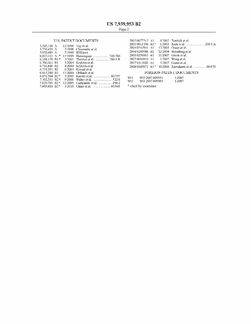
U.S. PATENT DOCUMENTS 2002fOO77512 A1 6/2002 Tendick et al. 2003/001 1196 A1 1/2003 Kern et al. .................... 290.1 A
5. A 123 Retic etal 2004/0242941 A1 12/2004 Green et al. 5928,985 A 7, 1999 Williams 2004/0245086 A1 12, 2004 Steynberg et al. 6,005,011 A * 12/1999 Henningsen .................. 518,706 2005/0250863 A1 11/2005 Green et al. 6,188,139 B1* 2/2001 Thaxton et al. ............... 290,4 R 2007/0004810 A1 1/2007 Wang et al. 6,706,661 B1 3/2004 Krylova et al. 2007, 0112080 A1 5, 2007 Green et al. 6,716,886 B2 4/2004 Krylova et al. 2008/0245071 A1* 10, 2008 Kawakami et al. ............. 60,670 6,753,351 B2 6/2004 Koveal et al. 6,815,388 B1 1 1/2004 Ohlbach et al. FOREIGN PATENT DOCUMENTS
ck 6,871,504 B2 * 3/2005 Kuroki et al. ................... 60/797 WO WO 2007/009.951 1, 2007 7,102.331 B2* 9/2006 Walter et al. ... ... 322.8 WO WO 2007/OO9965 1, 2007 7,629,701 B2 * 12/2009 Campanile et al. 290.2 7,669,418 B2 * 3/2010 Chino et al. .................... 60,645 * cited by examiner

U.S. Patent May 10, 2011 Sheet 1 of 8 US 7,939,953 B2
Governor
Turbine Governor Controller 6
Auxiliary POWer
Turbine Supply 2 Generator 1
Turbine
5 G () Field Current i46 2A2B 2 1A1B1
15E As 9 Hand
Disconnect Switch 1 7 Voltage
Measurements Measurements CD20
in as - 23 Close 1 1
Power Manager
1 8 Woltage
13
Plant Electrical Loads
14
FIG. 1


U.S. Patent May 10, 2011 Sheet 3 of 8 US 7,939,953 B2
Aggregate rating of DR Frequency difference Voltage difference Phase angle difference units (kVA) (Af, Hz) (AV,%) (Ad)
Colso H. > 500 - 500 0.2 5 5
> 500 - 0 000 0. 3 O
FIG, 7
FG. 8

U.S. Patent May 10, 2011 Sheet 4 of 8 US 7,939,953 B2
FIG 10

U.S. Patent May 10, 2011 Sheet 5 of 8 US 7,939,953 B2
6.3 Hz 600 Hz 59.7 Hz
FIG. 11
Wpeak = 679 W f = 600hz OK Wpeak = 702W f = 59.87 Hz. T
U.S. Patent May 10, 2011 Sheet 6 of 8 US 7,939,953 B2
3 Steam Supply
Governor Valve X/ ) 4. urbine Governor
7\ 21 Speed Controller 6 Fix
Turbine Auxiliary Turbine 2 Generator Power 1
Supply 5 G Speed Load Change
Commands
16
24 Merrins 25 27 MSAnts 26 CD CD
1 9 Woltage 17 Measurements 1 8 Woltage
Measurements
Open Close 22
Commands
Electrical loads
FIG. 13

U.S. Patent May 10, 2011 Sheet 7 of 8 US 7,939,953 B2
Plant Electrical Loads at time of Breaker Closure
" " . . Total Plant Electricatioads 7 /
/
/ Synchronizing P ynchronizing hower CD / Manager Programmed s Ramp Rate O /. n /
Steam Turbine / . iliary P Generator Load / . Auxiliary Power
/ . Supply Load
/ /
Time
: F.G. 14

U.S. Patent May 10, 2011 Sheet 8 of 8 US 7,939,953 B2
ls Turbine Near Rated Speed?
ls Steam Pressure Available
Start Turbine Enable Yes Synchronization Yes
No
Measure Auxiliary Power Supply D Voltage Frequency And Current
Surbie enerator Frequency
Greater than Auxiliary Power
Supply frequency Plus Offset
STurbine is turbine Generator enerator Frequency Woltage near Auxiliary Less than Power Supply Woltage? Auxiliary Power Supply
Frequency?
Do Frequency, Woltage, & Phase Angle of Turbine
Generator and Auxiliary Power Source allMatch to Within a tolerance?
issue Turbine
Close Command Use Governor to crease
Turbine Generator Frequency Use Woltage Regulator to Adjust ise Governor to increase
urbine Generator Woltage Turbine Generator Frequency
ls Turbine No Breaker
2 Have Auxiliary Power Closed Supply voltage and
Frequency Returned Yes start Turbine is Power Flow To Normal
Generator Load hrough Aulixary Powe s Auxiliary Power Supply Breaker Yes Supply a Utility? Near Okwe Ramp
Yes
Yes No
sAuxiliary Power Supply a Utility?
y
Issue Auxiliary Power Supply Breaker Open
Command System Stable in Utility Parallel
S. There a Utilit No Wottage frequency
Proble?
System Stable in island Mode No No
FIG. 15

US 7,939,953 B2 1.
MCRO SCALE FISCHER-TROPSCH AND OXYGENATE SYNTHESIS PROCESS
STARTUP UNIT
FEDERALLY SPONSORED RESEARCH
Not applicable.
REFERENCE TO MICROFICHEAPPENDIX
Not applicable.
FIELD OF THE INVENTION
This invention relates to equipment for starting up opera tions of a portable, Small, or micro, Scale Fischer-TropSch (“FT) and/or oxygenate synthesis unit for producing FT liquids an/or oxygenates from synthesis gases using natural gas, biomass, coal, or other carbon-containing compound as initial feedstocks.
BACKGROUND OF THE INVENTION
Synthesis gas (or 'syngas) is a mixture of primarily hydrogen and carbon monoxide, commonly with carbon dioxide, methane, water, nitrogen, and possibly other con stituents such as argon or helium. Syngas can be produced from any carbon containing feedstock, including natural gas, heavy petroleum cuts Such as resid or coke, bitumen, coal, or biomass by a variety of processes. Natural gas may be con verted to synthesis gas using steam methane reforming (“SMR), carbon dioxide reforming (“dry reforming), or a combination of these two processes, or by processes employ ing air, enriched air, or oxygen (generally with Some steam addition) Such as combined reforming, autothermal reform ing (ATR), catalytic partial oxidation (“CPOX) or thermal partial oxidation (“POX). When employed, enriched air or oxygen may be produced by conventional cryogenic air sepa ration, pressure swing adsorption (“PSA) or membrane pro cesses, the use of ion transport membranes ("ITM") or any other method producing a gas containing Sufficient oxygen. Heavier liquids or Solids, such as petroleum cuts and/or coal, are typically converted to synthesis gas by processes employ ing air, enriched air, or oxygen Such as gasification and cata lytic/thermal partial oxidation, again typically with some steam addition to the reaction mixture. Numerous synthesis gas production processes are well known in the art.
Liquid hydrocarbon products and oxygenates may be pro duced from Synthesis gas using any of a number of known processes. The liquid hydrocarbon products are referred to herein as 'synthetic crude.” As used herein, the term oxygen ate means any of (1) ethers, including, for example, ethyl tert-butyl ether (ETBE), diisopropyl ether (DIPE), dimethyl ether (DME), methyl tert-butyl ether (MTBE), tert-amyl ethyl ether (TAEE), tert-amyl methyl ether (TAME); and (2) methanol and C alcohols, including for example, ethanol (EtOH), propanol, butanol, tert-amyl alcohol (TAA), and tert butyl alcohol (TBA). Methanol is the most common oxygen ated product synthesized from Syngas.
Small and micro scale processes, including processes uti lizing certain portable equipment, are described in detail in U.S. application Ser. No. 12/040,500 filed on Feb. 29, 2008, entitled “Fischer-Tropsch and Oxygenate Synthesis Catalyst Activation/Regeneration in a Micro Scale Process the dis closure of which is incorporated by reference herein in its entirety.
5
10
15
25
30
35
40
45
50
55
60
65
2 Conventional Plant Start-Up Configuration
For a fixed-location land-based synthesis gas conversion plant (i.e., >500 bbl/day), there are a limited number of pos sibilities for performing FT or oxygenate synthesis plant start-ups. At one end of the spectrum, the plantis permanently connected to a large(r) electrical grid system, whereby at least some external (to the plant) electrical power is available at essentially all times. In this configuration, operation of all necessary start-up facilities and/or utilities (including, for example, the plant monitoring and control system, distilled and/or reverse osmosis water systems, inert gas generation, and/or start-up boilers) can be powered from external sources of electric power, e.g., a local power grid. At the other end of the spectrum, for example in a com
pletely remote plant site, stand alone, natural gas and/or liq uid fuel (e.g., diesel) start-up generators are typically pro vided to power all necessary start-up facilities and/or utilities. Because such facilities will generally require a number of on-site workers, there are a number of additional systems, Such as lighting, heating/vacuum/air conditioning (HVAC), potable water, Sanitary sewers, computers, and communica tions, that must also be maintained in operation. Conse quently, Some source of electrical power must be continu ously provided in Such remote plant sites.
There are, of course, a number of conceivable intermediate configurations between these extremes. For example, a small natural gas and/or liquid fuel generator could be provided with sufficient output to power a start-up steam boiler and the boilers control system. Once the boiler system and an asso ciated Steam turbine electrical generator are in operation, the remainder of the plant systems can be started up, utilizing the power from the steam turbine electrical generator. A natural gas fired turbine and/or micro-turbine electrical generator may be employed in a nearly identical way.
Regardless of the initial source of start-up power, all known synthesis gas-based FT and/or oxygenate synthesis processes produce large quantities of excess heat, particularly in the syngas generation and FT/oxygenate synthesis steps. Even for steam methane reforming generation of synthesis gas— which is typically known as an endothermic reaction—there is a great deal of excess energy in the combustion fuel gas stream which is used to supply the SMR reaction heat. The exothermic energy of syngas generation and liquid hydrocar bon and/or oxygenate synthesis is typically captured and employed to provide electrical and/or mechanical power for an entire plant during normal operations through the use of steam and/or other heat transfer medium Such as hot oil.
Steam may be directly employed as both a heating medium and source of rotating equipment shaft energy (i.e., steam turbine driven compressors), while electrical power genera tion may include both steam- and (external feed and/or tail) gas-turbine generators. In some instances, there may be sig nificant excess exothermic energy available after providing all required plant power, so that in non-remote locations or in more remote locations where a local external electric grid exists overall plant/project economics may be greatly improved through electrical power sales. Movable Plant Start-Up Configuration
For currently-proposed movable, predominantly offshore, plants practical options for the plant start-up power Supply are generally limited to local power generation. Therefore, Such synthesis plants are generally provided with start-up power generation facilities in the same manner as a completely isolated, land-based synthesis plant would be. An off-shore synthesis plant as part of a larger facility Such as an oil production platform, barge, or ship, would typically be able to employ the larger facility's local electrical power grid.

US 7,939,953 B2 3
Small or micro Scale liquid hydrocarbon and/or oxygenate synthesis units, however, may not, in Some instances, be able to Support the economics of providing complete start-up power generation equipment dedicated Solely to the Small or micro scale unit.
SUMMARY OF THE INVENTION
An embodiment of the invention provides a process for starting-up a liquid hydrocarbons and/or oxygenate synthesis plant, the process including the steps of Supplying a portable electrical generation system to a liquid hydrocarbons and/or oxygenate synthesis plant; connecting the portable electrical generation system to a power load of the synthesis plant; using electrical power from the portable electrical generation systems to start up a liquid hydrocarbons and/or oxygenate synthesis process; generating electricity from exothermic energy generated in the liquid hydrocarbons and/or oxygen ate synthesis process; synchronizing the electrical powergen erated by the portable electrical generation system and the electrical power generated by the exothermic energy; con necting the electrical power generated from the exothermic energy to the power load of the synthesis plant; and discon necting the portable electrical generation system from the synthesis plant. In some embodiments, synchronizing includes measuring one or more electrical parameters of the electrical power generated by the portable electrical genera tion system; measuring one or more electrical parameters of the electrical power generated from the exothermic energy of the synthesis process; adjusting the one or more electrical parameters of the electrical power generated from the exo thermic energy to match within preset tolerances the one or more electrical parameters of the electrical power generated by the portable electrical generation system. In some embodi ments, one or more electrical parameters are selected from the group of Voltage, phase angle, and frequency. In some embodiments, one or more electrical parameters is Voltage. In Some embodiments, the step of connecting the electrical power generated from the exothermic energy of the synthesis process to the power load of the synthesis plant further includes simultaneously connecting the electrical powergen erated from the exothermic energy to the portable electrical power generation system.
Another embodiment of the invention provides a system for providing start-up power to a liquid hydrocarbons and/or oxygenate synthesis plant including: a portable gas or liquid feed electrical generator, a steam turbine; a plant generator mechanically coupled to the Steam turbine; a plant power load; and means for synchronizing electrical power generated by the portable electrical generator and electrical powergen erated by the plant generator, wherein the portable electrical generator and plant generator are electrically couplable with the plant power load. In some embodiments, the system also includes a means for measuring one or more electrical param eters of the electrical power generated by the portable elec trical generator and/or the electrical power generated by the plant generator. In other embodiments, the system also includes Switch means for connecting and disconnecting the portable electrical generator and/or plant electrical generator to the plant power load. In other embodiments, the system also includes a control device capable of receiving signals from the means for measuring one or more electrical param eters and capable of changing the Switch means between open and closed positions. In some embodiments, one or more electrical parameters are Voltage, phase angle and frequency. In other embodiments, one or more electrical parameters is Voltage.
10
15
25
30
35
40
45
50
55
60
65
4 In some embodiments, the Switch means may be a first
connection device capable of connecting and disconnecting a first electrical power flow generated by the portable electrical generator with the plant power load and a second connection device capable of connecting and disconnecting a second electrical power flow generated by the plant generator with the plant power load. In some embodiments, the control device is further capable of measuring a first electrical power flow generated by the portable electrical generator and flow ing through the first connection device. In other embodi ments, the control device is further capable of comparing the first electrical power flow to a preset threshold value and determining whether the first electrical power flow is below the preset threshold value. In still other embodiments, the control device is further capable of measuring a second elec trical powerflow generated by the plant generator and flowing through the second connection device. In some alternative embodiments, the control device is further capable of com paring the second electrical power flow to a preset threshold value and determining whether the second electrical power flow is below the preset threshold value. In some embodi ments, the control device is further capable of causing said second power flow to increase at a predetermined rate or capable of detecting problems with the plant generator. In an alternate embodiment, the system may include one or more non-powered temperature dependent drain valves, a structure enclosing liquid hydrocarbons and/or oxygenate synthesis plant or a heating system to provide heat to the structure. In Some embodiments, the liquid hydrocarbons and/or oxygen ate synthesis plant is a hydrogenative pre-reformer. In alter nate embodiments, the system includes a large capacity power source, which is electrically couplable with the plant power load, and the means for synchronizing electrical power generated by the portable electrical generator and electrical power generated by the plant generator is also a means for synchronizing electrical power generated by the large capac ity power source and electrical power generated by the plant generator. In some embodiments, the control device is further capable of detecting problems with the large capacity power SOUC.
BRIEF DESCRIPTION OF THE DRAWINGS
FIG. 1 is a schematic showing the hardware topology for paralleling sources in a first embodiment of the invention.
FIG. 2 illustrates two separate unsynchronized 3-phase SOUCS.
FIG. 3 illustrates the voltage difference between sources requiring adjustment.
FIG. 4 illustrates two 3-Phase AC sources of different frequencies illustrated as not overlapping.
FIG. 5 illustrates signals for which the frequency and volt ages match but between which a phase angle difference exists.
FIG. 6 illustrates the waveforms of two perfectly synchro nized 3-phase AC Sources.
FIG. 7 is a table illustrating the threshhold tolerances for synchronizing a generator power source with a local grid in accordance with IEEE 1547.
FIG. 8 illustrates suitable voltage and phase-angle win dows in accordance with IEEE 1547.
FIG. 9 illustrates suitable voltage levels for paralleling two sources in accordance with IEEE 1547.
FIG. 10 illustrates suitable phase angle differences for paralleling two sources in accordance with IEEE 1547.
FIG. 11 illustrates suitable frequency difference for paral leling two sources in accordance with IEEE 1547.

US 7,939,953 B2 5
FIG. 12 illustrates example of suitable waveforms for par alleling two sources.
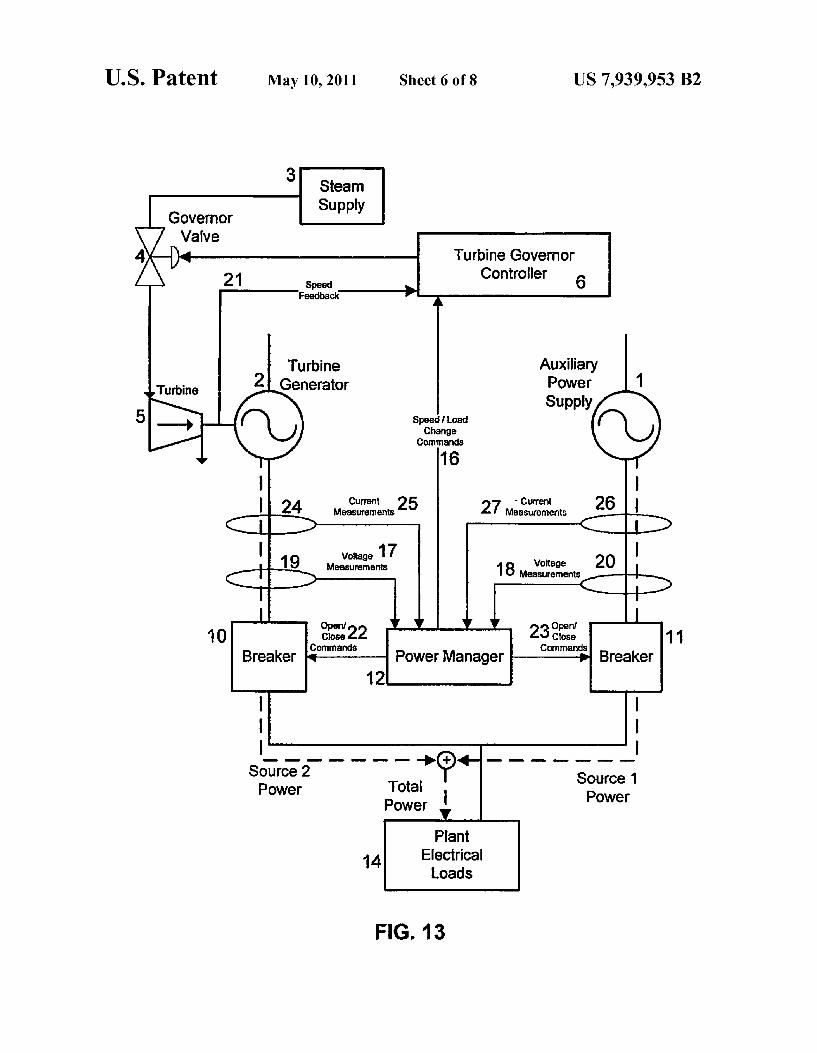
FIG. 13 illustrates power flows through paralleled systems in accordance with a preferred embodiment of the invention.
FIG. 14 illustrates power delivery load curves for equip ment during a soft transfer in accordance with an embodiment of the invention.
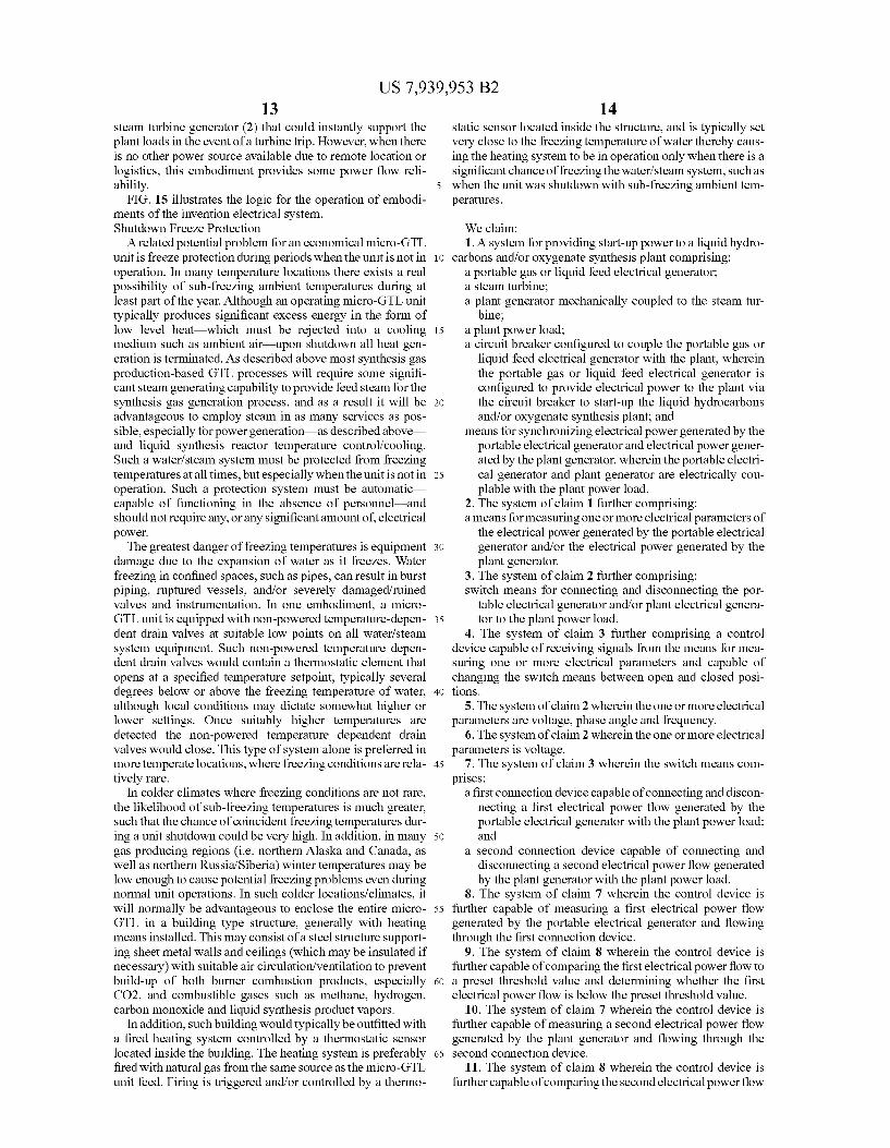
FIG. 15 illustrates the logic for system breaker control and synchronization in accordance with an embodiment of the invention.
DETAILED DESCRIPTION OF THE INVENTION
Micro-Scale FT and Oxygenate Synthesis Plants
There are proposed micro-scale FT and oxygenate synthe sis plants. In general, such plant capacities range from: (1) from about of 500 to about 1000 Mscfd natural gas feed rates, which are equivalent to from about 30 to about 100 bbl/day hydrocarbon liquids production capacity; or (2) about 1 to about 10 MMscfd, which are equivalent to from about 70 to about 1,000 bbl/day hydrocarbon liquids production capacity. There is in principle no reason that technically viable units could not be smaller still, in the range of 100-500 Mscfd (ca. 10-50 bbl/day); minimum size is strictly a function of eco nomic viability.
There are a number of constraints on the economic viabil ity of plants at this micro-scale. The most recent commercial conventional GTL plants actually constructed cost in the range of $950 million for 34,000 bbl/day FT liquid, or about S28,000 per bbl/day capacity. More recently engineering, procurement, and construction (“EPC) costs have increased such that currently forecasted GTL capital costs for plants to be constructed in the near future are in the range of $50,000 per bbl/day for similarly sized conventional plants. As plant size is increased from S to S, the ratio of costs increases nonlinearly, i.e., by Some power other than 1. For example, consider two conventional facilities having different capaci ties, S and S. The cost of the second facility (C) may be determined using a “scale factor' and the cost of the first facility (C), according to the formula, C=C *(S/S)', where “n” is the scalefactor. For n-1, costs rise at less than the ratio of plant size/capacity, so unit cost decreases yielding what is referred to as “economies of scale'. At a conventional plant scale factor of 0.6 these cost projections suggest that a 50-100 bbl/day unit would cost in the range of S19-29 million (at S28,000 per bbl/day for the larger, conventional unit) to $34-51 million (at $50,000 per bbl/day). Using the more recent specific capital cost prediction of S50,000 per bbl/day capacity, and assuming a $50/bbl product price, the ratio of plant capital cost to total plant yearly revenue would vary from about 3.0 for a 34,000 bbl/day plant to 31 at 100 bbl/day and 40 at 50 bbl/day. Even with Zero costs for operating and maintenance (all revenue is profit) the time to payback initial investment on Such micro-scale plants would clearly be longer than the typical plant lifespan of 20-30 years. With the same S50/bbl product value assumption, actual total yearly revenues for these micro-scale 50-100 bbl/day plants would range from about $850,000 to $1,600,000. Thus, to achieve economic feasibility, plant capital investment costs for these micro-scale plants must be significantly lower than the values predicted from large plant configurations, approaching a fac tor of 10 (or more) times lower, and annual total operating and maintenance costs must be much lower than the relatively Small total annual revenue stream. To achieve these economic targets, certain changes to con
ventional plants are required. On the capital cost side, the
10
15
25
30
35
40
45
50
55
60
65
6 process may be simplified, with the number of unit operations minimized. The number of vessels, instruments, and rotating equipment should be minimized. Plants are preferably not individually designed and engineered, but rather are engi neered as a small number of Standard designs that may be mass produced. The units may be shop fabricated, modular, and fit within normal truck bedshipping size constraints, e.g., 8 ft.x10 ft.x40 ft., and less than about 20 tons total weight. Alternatively, a single processing unit may be shop fabricated in more than one module, depending on targeted capacity. For the very exothermic syngas generation and FT/oxygenate synthesis processes, heat exchanger size may be minimized, utilizing, for example, advanced finned tube designs. In some instances, utilities that are absolutely required (typically elec trical power and boiler feed water/steam systems) may be applied as widely as possible, minimizing the number of different utilities included in the plant package.
In some embodiments of the invention, the syngas produc tion includes use of a hydrogenative pre-reformer. Pre-re formers for use in Syngas generation are described in detail in U.S. application Ser. No. 12/061,355, filed on Apr. 2, 2008, entitled “Hydrogenating Pre-Reformer in Synthesis Gas Pro duction Processes, the disclosure of which is incorporated in its entirety herein by reference.
Operating costs may also be subject to similar constraints. In some instances, the plants may be highly, if not completely, automated. In other instances, the automated control systems may be capable of remote monitoring and control. In some instances, feed costs may be minimized, by use, for example, of stranded and/or non-pipeline standard (Sub-quality) natu ral gas, most types of coal, and/or waste-stream biomass (including but not limited to, poultry litter, sawmill wastes, agricultural residues, (Kraft paper process) black liquor, municipal Solid waste).
Maintenance frequency and costs may also be minimized by judicious equipment selection and process design and layout. In some instances, connections are welded (to avoid leaks associated with gaskets and fittings) except where main tenance constraints dictate flanges or other non-welded con nections. Small-scale materials of construction consider ations will typically lead to “alloying up' to FeCr (or higher) alloys, compared to the more common large plant carbon steels.
It will be apparent to one of ordinary skill in the art that the foregoing embodiments of the invention may be practiced in connection with processes that produce: (1) only Fischer Tropsch products; (2) only oxygenate products; or (3) a com bination of Fischer-Tropsch and oxygenate products, and par ticularly Fischer-Tropsch products and methanol. Start-Up of Micro-Scale FT and Oxygenate Synthesis Plants The start-up power requirements for micro-scale FT and/or
oxygenate synthesis processes are similar to, though typically simpler than, those required for larger scale offshore/mobile and/or land-based plants described above. This is primarily due to the absence of operation staff. Such that lighting, HVAC, potable water, and sanitary sewers systems need not be maintained at all times, and actually may not be required at all. Some external source of electricity for control system and at least minimal equipment operation will still be necessary for plant start-up.
In some micro-scale "stranded gas' locations—such as oil production facilities with associated gas—as well as many micro-scale biomass/waste locations, Some type of electrical grid will typically be present or easily available. In these cases micro-scale unit start-ups would proceed much like those for larger plants with access to an external grid discussed above,

US 7,939,953 B2 7
although there will be different considerations with regard to the power Switching equipments and methods (described in more detail below).
For micro-scale GTL units in truly remote locations— particularly in the absence of any external electrical power grid providing for unit start-up power is more problematic. While Suitably sized power generation equipment Such as (natural gas fueled) micro-turbine generators, as well as natu ral gas and/or liquid fueled combustion generators are com mercially readily available, the size and cost of these units severely debits the economics of the micro-scale GTL pro cess, particularly if these generators were only employed for unit start-ups. As in the case of larger synthesis gas based FT and/or
oxygenate synthesis processes, micro-scale units produce large amounts of “excess' heat from the exothermic syngas generation and FT and/or oxygenate synthesis processes. One obvious possibility is to capture this energy to provide unit power during plant operations. In general Some type of steam system will be required to provide feed steam for the synthe sis gas generation process, and as it is economically advan tageous to minimize the number of micro-scale unit utilities, the wider use of steam is generally beneficial. This would typically include, for example, steam generation by cooling the hot synthesis gas product and/or by cooling, removing heat from, and/or temperature control of the FT and/or oxy genate synthesis reactors, as well as providing energy for various heater duties and powering a steam turbine electrical generator. This electrical power would, in turn, be employed driving various mechanical devices Such as pumps, compres sors, and fans, as well as powering all plant electronics and electrical systems. Excess steam (left over after all heating and power generation duties) would be condensed, typically in against air in air-fin heat exchangers, but the quantity of excess steam would be relatively small in a judiciously designed unit. This configuration would maximize unit effi ciency, particularly if at least some portion of the FT and/or oxygenate synthesis process tail gas was combusted to pro duce additional steam. However, it would, in general, be impossible to start this unit up “as is” (i.e. without some additional start-up equipment).
At the other extreme, we could envision a unit where all required power for both start-up and normal operations is provided by a fueled generator. This generator could be pow ered by a natural gas (NG) micro-turbine or a NG or liquid fuel combustion engine. While this configuration could be readily started up and operated, there are a number of very significant, mainly economic, debits against it.
Total micro-GTL power requirements are—of course—a function of both detailed process design and power genera tion hardware. Consider a micro-scale unit feeding 500,000 standard cubic feed per day (500 kscfd) of natural gas (NG). Assuming a typical heat content of 1,200 BTU per standard cubic foot (SCF), this feed would represent an energy content of 600 million BTU/day, or just over 24 million BTU/hr, which is about 7.3 million watts. The electrical power requirements for a typical FT and/or oxygenate synthesis unit of this scale would be expected to be between 100 and 200 kilovolt-amps (KVA), or about 85 to 170kilowatts (KW). The efficiency of a relatively simple combustion or turbine elec trical generator, especially one not including heat recovery steam generation (HRSG), is typically in the range of 30-35%, and in no case exceeds 40%. Assuming a typical efficiency of 25% for Small unit power generation, producing 85-170 KW from feed NG combustion would consume 340 680 KW of NG, or 4.5 to about 9.0% of the total unit feed.
10
15
25
30
35
40
45
50
55
60
65
8 At a conventional large plant scale the typical thermal
efficiency of gas-to-liquid processes range from perhaps 50-60% for FT based processes to 60-70% for methanol production. At the much smaller micro-GTL scale thermal efficiencies are expected to be somewhat lower, in the range of 40-50% for FT and 50-60% for methanol. A 4.5 to 9% decrease in feed natural gas (to account for gas consumption in power generation) would therefore be expected to result in about a factor of 2 larger percentage decrease in liquid pro duction (ca. 10-20%), and therefore total potential revenue. At the same time, the excess energy produced in the pro
cess—that would otherwise be consumed in power genera tion—must instead be rejected elsewhere, typically by con densing Steam. This results in a very large increase in heat exchanger/condenser sizes and power consumption. The eco nomics of this micro-GTL plant configuration are clearly less than ideal.
Finally it would also be necessary to ensure that the air intake of the ICE never contains flammable gases, a not insignificant challenge given the overall Small size of the entire micro-GTL unit. An intermediate case would be combining the first
option—normal plant power produced by harnessing the exo thermicheat of reaction from the syngas generation and liquid hydrocarbon and/or oxygenate synthesis processes—with a Smaller, gas or liquid fueled generator for plant start-up pur poses only. This option would not result in the very large efficiency debits described above, but would result in “extra’ equipment in the micro-GTL plant. Because the start-up gen erator would be only perhaps 25-35% of the capacity of the larger, steady-state operation generator, it’s cost would be relatively small, in the range of only about 1-2% of the total unit capital cost, especially for internal combustion engine (ICE) generators. Natural gas, gasoline, or diesel ICE gen erators are available; for micro-GTL natural gas fueled machines are preferred. Natural gas fueled micro-turbine generators, which might be considered alternative possibili ties, are typically in the range of 4-8 times as expensive, and can probably be ruled out of this service on capital cost alone. The effectiveness of installing a smaller start-up generator
is critically dependent on achieving truly unattended start-up capability of the micro-GTL unit. In order to be economic in the first place the micro-GTL unit must be designed for more or less completely unattended operations, as the total plant revenue stream is broadly equivalent to the costs associated with full time staffing. However, as soon as the start-up pro cess/procedure requires on site staffing which is generally the case—the preferred solution will be shifted to the start-up operator(s) bringing the start-up generator out with them, typically as a truck- or skid-mounted unit. There are also potential problems associated with remotely starting up a start-up generator incorporated in the micro-GTL unit in the event of a unit shutdown/trip (which will terminate the steady state power generation and possibly the unit control system if separate back-up power for this system is not included). This “black start” requirement might then entail the addition of battery back-up power, at Some non-trivial additional cost, weight, and size. A related configuration employing only installed battery
back-up power including significant investment for DC-AC inverter equipment—for start-up can generally be ruled out on cost and effectiveness terms. Providing power for one start-up will typically cost in the range of 2-3 times as much as a similarly sized ICE generator. But start-up procedures/ processes are themselves Subject to unexpected shutdowns and trips (especially during periods immediately following a previous unit shutdown/trip), and if a shutdown occurs prior
US 7,939,953 B2
to establishing operation of the unit power generation equip ment and sufficient time to recharge the batteries, the latter will be completed drained prior to establishing normal opera tions. This potential problem can be mitigated to some extent by oversizing the battery back-up system, but is still vulner able to complete battery discharge in extended or multi-trip start-ups. Size and weight of the required battery back-up system are also a significant debit in a micro-GTL unit. The preferred embodiment of the current invention
employs a steam turbine generator for electrical power pro duction during normal plant operations, as described above. Start-up and controlled shutdown power is provided by either an electrical grid, if available, or, more commonly, a portable, truck mounted gas or liquid fueled generator in the absence of a grid. In order to start-up the unit following a shutdown— either controlled or emergent—operations/start-up personnel would bring the start-up unit to the remote facility and per form the start-up procedure, after which Such personnel and the equipment needed to Supply electrical power for start-up depart.
Another preferred embodiment of the current invention in the absence of a local power grid also employs a very low capacity (typically 5-10 kW) solar power generator and bat tery back-up system to maintain operations of the microGTL control and monitoring systems when the unit is not operat ing. At a minimum Such a back-up system is required to differentiate a true unit shutdown—and hence loss of data transfer to a separate/remote monitoring facility—from a loss of communication from an otherwise operating unit. The control and monitoring system preferably consist of a pro grammable logic controller (PLC) and a Supervisory control and data acquisition (SCADA) system, although other hard ware systems and types are known. Where a portable electrical power supply is used for start
up of a plant, it will be necessary to synchronize, or parallel, the electrical power supplied by the portable supply with the electrical power generated from the exothermic energy dur ing the transfer from the portable power supply. Moreover, if a liquid hydrocarbon and/or oxygenate synthesis plant pro duces excess electrical energy beyond that needed by plant and Such excess electrical energy is to be uploaded onto an external electrical grid, such excess electrical power must be synchronized with the grid power. Synchronizing Electrical Power
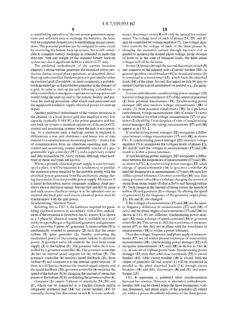
Referring first to FIG. 1, the hardware required for paral leling electrical Sources in accordance with a first embodi ment of the invention is described. An AC source (1) is shown as a 3-phase AC electrical source that is available as a local utility or a portable gas or liquid feed generator, and generator (2) is a movable 3-phase AC generator. A steam turbine (5) is mechanically coupled to generator (2) Such that the steam turbine (5) spins generator (2), thereby converting the mechanical power of the rotating steam turbine to electrical power. A governor valve (4) controls the feed from steam supply (3) to the turbine (5). The governor valve (4) is con trolled by a governor controller (6). The governor controller (6) has an internal speed setpoint for the turbine (5). The governor controller (6) receives speed feedback (21) from turbine (5) and compares it to the internal speed setpoint. If there is a difference between the internal speed setpoint and the speed feedback (21), governor controller (6) modifies the speed of the turbine (5) by changing the amount of steam that passes to the turbine (5) by modulating the governor valve (4).
Generator (2) outputs 3 phases of electricity 2A, 2B, and 2C, which can be connected to a Fischer-Tropsch and/or oxygenate synthesis unit (14) via circuit breaker (10) by manually closing first disconnect Switch 8. In some embodi
10
15
25
30
35
40
45
50
55
60
65
10 ments, disconnect switch 8 will only be opened for mainte nance. The voltage level of each of phases 2A, 2B, and 2C may be controlled by Voltage regulator (7). The Voltage regu lator controls the voltage of each of the three phases by changing the excitation current through the rotor coil as needed to maintain the desired phase Voltage. In the absence of loads or in the case of balanced loads, the three phase voltages will all be the same.
Source (1) passes through the second disconnect switch (9) and connects to the primary side of circuit breaker (11). In general operation circuit breaker (11) is closed and source (1) is connected to a transformer (13), which feeds the electrical loads (14) of the plant. Second disconnect switch (9) may be opened (and the circuit interrupted) as needed, e.g., for main tenance.
In some embodiments, synchronizing power manager (12) receives Voltage measurements (17) of the output of generator (2) from potential transformers (19). Synchronizing power manager (12) also receives Voltage measurements (18) of source (1) from potential transformers (20). In a preferred embodiment, Voltage measurements (18) of Source (1) serve as the reference for what voltage measurements (17) of gen erator (2) should be. From the point of view of synchronizing power manager (12), the Voltage measurements (17) and (18) appear as in FIG. 2.
If synchronizing power manager (12) recognizes a differ ence between voltage measurements (17) and (18), as shown FIG. 3, Synchronizing power manager (12) instructs Voltage regulator (7) to manipulate the Voltages levels of phases 2A, 2B, and 2C until the voltages in measurements (17) and (18) match to within a preset tolerance.
If synchronizing power manager (12) recognizes a differ ence between the frequencies of measurements (17) and (18), as shown in FIG. 4, Synchronizing power manager (12) sends change of speed commands (16) to governor controller (6) until the frequencies in measurements (17) and (18) match to within a preset tolerance. Governor controller (16) may then cause governor valve (4) to modulate, changing the amount of steam from steam supply (3) that is fed to and through turbine (5). Such change in the amount of steam causes the speeds of turbine (5) and generator (2) to change. By altering the speed of generator (2), the frequency of the generator output phase 2A, 2B, and 2C are changed.
If the voltages of measurements (17) and (18) are the same, (a frequency difference in measurements (17) and (18) of Zero), and the phase angles of measurements (17) and (18) (as shown in FIG. 5), are different; synchronizing power man ager (12) sends a change of speed command (16) to governor controller (6). This serves to shift the waveforms of measure ments (17) so that they are in phase with the waveforms of measurements (18) to within a preset tolerance. Once the Voltage, frequency, and phase angle of measure
ments (17) are all within present tolerances of concomitant measurements (18), Synchronizing power manager (12) will recognize measurements (17) and (18) as shown in FIG. 6; i.e., as one set of 3-phase power lines. Synchronizing power manager (12) may then send close commands (22) to circuit breaker (10). After circuit breaker (10) is closed, both the output of generator (2) and source (1) will be connected in parallel to the plant electrical loads (14) through circuit breakers (10) and (11), disconnects (8) and (9), and trans former (13).
FIG. 6 represents a preferred ideal synchronization between two sources. However, in alternative embodiments, breaker (10) can be closed when the three parameters, volt age, frequency, and phase angle, of the generator (2) output are within a preset threshhold tolerance of the three param

US 7,939,953 B2 11
eters of the source (1). IEEE 1547, Standard for Interconnect ing Distributed Resources with Electric Power Systems, offers threshold tolerances for performing the synchroniza tion. Such threshold tolerances are listed in the table of FIG. 7.
In those embodiments employing the tolerances prescribed by IEEE 1547, windows of possible voltages and phase angle differences are created about the reference waveform of Source 1, as seen in FIG. 8.
FIG. 9 shows two potential generator (2) single phase waveforms that precisely match source (1) in frequency and phase angle, but differ in voltage within IEEE 1547 pre scribed tolerances for closing circuit breaker (10).
FIG. 10 shows two potential generator (2) single phase waveforms that precisely match Source (1) in Voltage and frequency, but differ in voltage within IEEE 1547 prescribed tolerances for closing circuit breaker (10).
FIG. 11 shows two potential generator (2) single phase waveforms that precisely match source (1) in Voltage but differ in frequency within IEEE 1547 prescribed tolerances for closing circuit breaker (10).
For breaker (10) to close for either of the generator (2) waveforms in FIG. 11 (shown as a solid line), then there must be a continuous monitoring of the phase angle difference Add Such that the breaker close command occurs within a window of time where the Add is within limits.
FIG. 12 shows a sample suitable waveform for paralleling the generator (2) and Source (1). Although these waveforms do not overlap perfectly, all parameters are within present tolerances in the time window shown. Once circuit breaker (10) is closed the steam turbine gen
erator (2) and source (1) are electrically connected to each other, the phase angle difference of their voltages is necessar ily 0 degrees, because there are no longer two Voltages. This assumes negligible impedance of conductors and equipment between them.
The parallel connected systems will have power flows as shown by the lines in FIG. 15. The total power is whatever the plant system needs to run. Its magnitude is not optional or negotiable, and is decided by the process loads and control system power consumption. The synchronizing power man ager (12) determines the magnitude of Source 2 power, and the source 1 power is the difference between the total power and source 2 power allowed by the synchronizing power manager (12). The synchronizing power manager (12) performs fast, reli
able measurements of the power through each circuit breaker using potential transformers (19 and 20) and current trans formers (24 and 26).
After the two sources are connected, the controllable parameter of the governor controller (6) is no longer the speed of the turbine. Instead the controllable parameter becomes the mechanical power delivered by the turbine (5) to the genera tor (2). Hence, the speed change commands (16) issued by the synchronizing power manager (12) become load change commands (16). With the load change commands (16) the synchronizing power manager (12) can control how much electrical power is delivered by the generator (2).
In some embodiments, the synchronizing power manager (12) includes an operating mode called import/export. The import/export mode controls the amount of power that is imported from or exported to whatever is upstream of circuit breaker (11). The synchronizing power manager (12) controls this amount by adjusting the other source of power, the steam turbine generator (2). If the available power from generator (2) is zero, as in when circuit breaker (10) is open (before synchronization), the synchronizing power manager (12) is
10
15
25
30
35
40
45
50
55
60
65
12 Smart enough to know this and it will not attempt to adjust the power delivered by the steam turbine generator (2) until cir cuit breaker (10) is closed. The plant will use the import/export mode of the synchro
nizing power manager (12) with a setpoint of 0 kW. This means that when the synchronizing power manager (12) rec ognizes that circuit breaker (10) and circuit breaker (11) are both closed, the synchronizing power manager (12) will begin to attempt to make the power flow through circuit breaker (11) equal to 0 kW. It will do this by increasing the load delivered by generator (2). It will achieve that by sending load change commands (16) of the “increase load' type. Synchronizing power manager (12) will control the rate of the increase load commands as described below.
If, during the transfer of load from Source (1) to generator (2) the total power consumed by the plant loads does not change, FIG. 14 show the time-varying magnitudes of the three loads of FIG. 15 This limitation is imposed only to simplify the graph. In reality the total load can change, giving the pink line a slope.
Immediately after the synchronizing power manager (12) sends close command (22) to circuit breaker (10), circuit breaker (10) closes and source (1) and generator (2) operate in parallel. The initial load delivered by generator (2) is very small (shown as Zero in FIG. 18) and after a short time, synchronizing power manager (12) uses load change com mands (16) to increase the power delivered by the steam turbine generator (2). The rate at which the load is introduced to the generator (2) is a configurable parameter of synchro nizing power manager (12). The ramp rate will be set to a conservative value. It is the ramp rate of load introduction to the steam turbine generator (2) that determines the increase in steam consumption, which determines the upset to the steam raising portion of the plant. As an option, we may wish to control the ramp rate is controlled with an analog input to the synchronizing power manager (12), the magnitude of the analog signal being determined by the steam raising process, for example, by a watchdog on the steam generator level.
After the ramp illustrated in FIG. 14 has completed the entire load of the plant may be supplied by the steam turbine generator (2).
In those instances in which the source (1) is an infinite grid ora plant distribution system, circuitbreaker (11) may remain closed and the import/export mode for synchronizing power manager (12) may remain active. Sudden changes in load will usually be supplied by Source (1). Synchronizing power man ager (12) may respond by increasing the load delivered by steam turbine generator (2) bring the power flow through circuit breaker (11) back to its setpoint of OkW. This process provides high reliability of power flow. With the steam tur bine generator (2) and the grid connected in parallel and with the electrical load being supplied completely by the steam turbine generator (2), the grid may be instantly and fully available to Support the plant loads in the event of a steam turbine trip. Under normal circumstances, and in some embodiments, the power draw from the external power grid is 0 kW, such that no external power must be bought. The only times the owner pays to power the plant are during a startup and in the event of a turbine trip.
If source (1) is a standby generator, at the time that Syn chronizing power manager (12) recognizes that the power flow through circuit breaker (11) is below a threshold near 0 kW (e.g. 5 kW), synchronizing power manager (12) will send an open command (23) to circuit breaker (11), thereby dis connecting source (1) from the plant loads.
This embodiment offers lower power flow reliability as there is no other source of power connected in parallel to the
US 7,939,953 B2 13
steam turbine generator (2) that could instantly Support the plant loads in the event of a turbine trip. However, when there is no other power source available due to remote location or logistics, this embodiment provides some power flow reli ability.
FIG. 15 illustrates the logic for the operation of embodi ments of the invention electrical system. Shutdown Freeze Protection A related potential problem for an economical micro-GTL
unit is freeze protection during periods when the unit is not in operation. In many temperature locations there exists a real possibility of Sub-freezing ambient temperatures during at least part of the year. Although an operating micro-GTL unit typically produces significant excess energy in the form of low level heat which must be rejected into a cooling medium such as ambient air upon shutdown all heat gen eration is terminated. As described above most synthesis gas production-based GTL processes will require some signifi cant steam generating capability to provide feed Steam for the synthesis gas generation process, and as a result it will be advantageous to employ steam in as many services as pos sible, especially for power generation—as described above and liquid synthesis reactor temperature control/cooling. Such a water/steam system must be protected from freezing temperatures at all times, but especially when the unit is not in operation. Such a protection system must be automatic— capable of functioning in the absence of personnel—and should not require any, or any significant amount of electrical power. The greatest danger of freezing temperatures is equipment
damage due to the expansion of water as it freezes. Water freezing in confined spaces, such as pipes, can result in burst piping, ruptured vessels, and/or severely damaged/ruined valves and instrumentation. In one embodiment, a micro GTL unit is equipped with non-powered temperature-depen dent drain valves at suitable low points on all water/steam system equipment. Such non-powered temperature depen dent drain valves would contain a thermostatic element that opens at a specified temperature setpoint, typically several degrees below or above the freezing temperature of water, although local conditions may dictate somewhat higher or lower settings. Once Suitably higher temperatures are detected the non-powered temperature dependent drain valves would close. This type of system alone is preferred in more temperate locations, where freezing conditions are rela tively rare.
In colder climates where freezing conditions are not rare, the likelihood of Sub-freezing temperatures is much greater, Such that the chance of coincident freezing temperatures dur ing a unit shutdown could be very high. In addition, in many gas producing regions (i.e. northern Alaska and Canada, as well as northern Russia/Siberia) winter temperatures may be low enough to cause potential freezing problems even during normal unit operations. In Such colder locations/climates, it will normally be advantageous to enclose the entire micro GTL in a building type structure, generally with heating means installed. This may consist of a steel structure Support ing sheet metal walls and ceilings (which may be insulated if necessary) with suitable air circulation/ventilation to prevent build-up of both burner combustion products, especially CO2, and combustible gases Such as methane, hydrogen, carbon monoxide and liquid synthesis product vapors.
In addition, such building would typically be outfitted with a fired heating system controlled by a thermostatic sensor located inside the building. The heating system is preferably fired with natural gas from the same source as the micro-GTL unit feed. Firing is triggered and/or controlled by a thermo
10
15
25
30
35
40
45
50
55
60
65
14 static sensor located inside the structure, and is typically set very close to the freezing temperature of water thereby caus ing the heating system to be in operation only when there is a significant chance of freezing the water/steam system, Such as when the unit was shutdown with sub-freezing ambient tem peratures.
We claim: 1. A system for providing start-up power to a liquid hydro
carbons and/or oxygenate synthesis plant comprising: a portable gas or liquid feed electrical generator, a steam turbine; a plant generator mechanically coupled to the Steam tur
bine; a plant power load; a circuit breaker configured to couple the portable gas or
liquid feed electrical generator with the plant, wherein the portable gas or liquid feed electrical generator is configured to provide electrical power to the plant via the circuit breaker to start-up the liquid hydrocarbons and/or oxygenate synthesis plant; and
means for synchronizing electrical power generated by the portable electrical generator and electrical power gener ated by the plant generator, wherein the portable electri cal generator and plant generator are electrically cou plable with the plant power load.
2. The system of claim 1 further comprising: a means for measuring one or more electrical parameters of
the electrical power generated by the portable electrical generator and/or the electrical power generated by the plant generator.
3. The system of claim 2 further comprising: Switch means for connecting and disconnecting the por
table electrical generator and/or plant electrical genera tor to the plant power load.
4. The system of claim 3 further comprising a control device capable of receiving signals from the means for mea Suring one or more electrical parameters and capable of changing the Switch means between open and closed posi tions.
5. The system of claim 2 wherein the one or more electrical parameters are Voltage, phase angle and frequency.
6. The system of claim 2 wherein the one or more electrical parameters is Voltage.
7. The system of claim 3 wherein the switch means com prises:
a first connection device capable of connecting and discon necting a first electrical power flow generated by the portable electrical generator with the plant power load; and
a second connection device capable of connecting and disconnecting a second electrical power flow generated by the plant generator with the plant power load.
8. The system of claim 7 wherein the control device is further capable of measuring a first electrical power flow generated by the portable electrical generator and flowing through the first connection device.
9. The system of claim 8 wherein the control device is further capable of comparing the first electrical power flow to a preset threshold value and determining whether the first electrical power flow is below the preset threshold value.
10. The system of claim 7 wherein the control device is further capable of measuring a second electrical power flow generated by the plant generator and flowing through the second connection device.
11. The system of claim 8 wherein the control device is further capable of comparing the second electrical power flow

US 7,939,953 B2 15 16
to a preset threshold value and determining whether the sec- 13. The system of claim 4 wherein the control device is ond electrical power flow is below the preset threshold value. further capable of detecting problems with the plant genera
12. The system of claim 7 wherein the control device is tOr. further capable of causing said second power flow to increase at a predetermined rate. k . . . .