Embed Size (px)
Citation preview

12-1
Chapter 12Rotational Motion
CHAPTER 12 ROTATIONAL MOTION
Our discussion of rotational motion begins with areview of the measurement of angles using the conceptof radians. We will refer to an angle measured inradians as an angular distance. If we are discussingan object that is rotating, we will describe the rotationin terms of the increase in angular distance, namely anangular velocity. And if the speed of rotation ischanging, we will describe the change in terms of anangular acceleration.
In Chapter 7, linear momentum and angular momen-tum were treated as distinctly separate topics. Themain point of this chapter is to develop a close analogybetween the two concepts. The linear momentum of anobject is its mass m times its linear velocity v . We willsee that angular momentum can be expressed as anangular mass times an angular velocity. (Angularmass is more commonly known as moment of inertia).Then, using the formalism of the vector cross product(mentioned in Chapter 2), we will see that angularmomentum can be treated as a vector quantity, whichexplains the bicycle wheel experiments we discussed inChapter 7.
The fundamental concept of Newtonian mechanics isthat the total force F acting on an object is equal to thetime rate of change of the object’s linear momentum;
F = dp/dt . Using the vector cross product formalism,we will obtain a complete angular analogy to thisequation. We will find that a quantity we call an
angular force is equal to the time rate of change ofangular momentum. (The angular force is more com-monly known as torque).
The angular analogy to Newton’s second law looks abit peculiar at first. It involves lever arms and vectorsthat point in funny directions. After some demonstra-tions to show that the equation appears to give reason-able results, we apply the equation to predict themotion of a gyroscope. The prediction appears to beabsurd, but we find that that is the way a gyroscopebehaves.
Our focus in this chapter is on angular momentumbecause that concept will play such an important rolein our later discussions of atomic physics and electronsand nuclear magnetic resonance. There are otherimportant and interesting topics such as rotationalkinetic energy and the calculation of moments ofinertia which we discuss in more detail in the appendix.These topics are not difficult and lead to some goodlecture demonstrations and laboratory experiments.We put them in an appendix because they do not playthe essential role that angular momentum does in ourlater discussions.

12-2 Rotational Motion
RADIAN MEASUREFrom the point of view of doing calculations, it is moreconvenient to measure an angle in radians than themore familiar degrees. In radian measure the angle θshown in Figure (1) is the ratio of the arc length s to theradius r of the circle
θ ≡ s
r radians (1)
Since s and r are both distances, the ratio s/r is adimensionless quantity. However we will find itconvenient for the angular analogy to keep the nameradians as if it were the actual dimension of the angle.For example we will measure angular velocities inradians per second, which is analogous to linearvelocities measured in meters per second.
Since the circumference of a circle is 2πr , the numberof radians in a complete circle is
θ completecircle = 2πr
r = 2π
In discussing rotation, we will often refer to goingaround one complete time as one complete cycle. Inone cycle, the angle θ increases by 2π. Thus 2π is thenumber of radians per cycle. We will find it conve-nient to assign these dimensions to the number 2π:
2π radians
cycle (2)
To relate radians to degrees, we use the fact that thereare 360 degrees/cycle and dimensional analysis to findthe number of degrees/radian
360 degreescycle × 1
2πcyclesradian
= 3602π
degreesradian = 57.3 degrees
radian
(3)
Fifty seven degrees is a fairly awkward unit angle forpurposes of drafting andnavigation; no one in his orher right mind would marka compass in radians. How-ever, in working with thedynamics of rotational mo-tion, radian measure is the only reasonable choice.
Angular VelocityThe typical measure of angular velocity you may befamiliar with is revolutions per minute (RPM). Thetachometer in a sports car is calibrated in RPM; atypical sports car engine gives its maximum poweraround 5000 RPM. Engine manufacturers in Europeare beginning to change over to revolutions per second(RPS), but somehow revving an engine up to 83 RPSdoesn't sound as impressive as 5000 RPM. (Tachom-eters will probably be calibrated in RPM for a while.)In physics texts, angular velocity is measured in radiansper second. Since there are 2π radians/cycle, 83revolutions or cycles per second corresponds to
2π × 83 = 524 radians/second. Few people wouldknow what you were talking about if you said that youshould shift gears when the engine got up to 524 radiansper second.
Exercise 1
What is the angular velocity, in radians per second,of the hour hand on a clock?
Figure 1The angle θθ in radians is defined as the ratioof the arc length s to the radius r: θθ = s/r .
r
sθ
1 radian = 57.3o

12-3
Angular AnalogyAt this point we have a complete analogy between therotation of a motor shaft and one dimensional linearmotion. This analogy becomes clear when we write outthe definitions of position, velocity, and acceleration:
(7)
As far as these equations go, the analogy is precise.Therefore any formulas that we derived for linearmotion in one dimension must also apply to angularmotion. In particular the constant acceleration formu-las, derived in Chapter 3, must apply. If the linear andangular accelerations a and α are constant, then we get
Constant Acceleration Formulas Linear motion (a = const) Angular motion (αα = const)
x = v0t +
12
at2 θ = ω0 t +12α t2 (8)
v = v0 + at ω = ω 0 + αt (9)
Exercise 2An electric motor, that turns at 3600 rpm (revolutions perminute) gets up to speed in 1/2 second. Assume that theangular acceleration α was constant while the motorwas getting up to speed.
a) What was α (in radians/ sec2 )?
b) How many radians, and how many complete cycles,did the shaft turn while getting up to speed?
θ (t)
ω
Figure 2End of a shaft rotating at an angular velocity ω .
Our formal definition of angular velocity is the timerate of change of an angle. We almost always use theGreek letter ω (omega) to designate angular velocity
angularvelocity ω ≡ dθ
dtradianssecond
(4)
When thinking of angular velocity ω picture a linemarked on the end of a rotating shaft. The angle θ isthe angle that the line makes with the horizontal asshown in Figure (2). As the shaft rotates, the angle θ tincreases with time, increasing by 2π every time theshaft goes all the way around.
Angular AccelerationWhen we start a motor, the angular velocity of the shaftstarts at ω = 0 and increases until the motor gets up toits normal speed. During this start-up, ω t changeswith time, and we have an angular acceleration αdefined by
angular
accelerationα ≡
dωdt
radians
second2 (5)
The angular acceleration α has the dimensions of radians/sec2 since the derivative gives us another
factor of time in the denominator. Combining Equa-tion 4 and 5 relates α to θ by
α =d2θ
dt2(6)
Linearmotion
x meters
v = dxdt
meterssecond
a =dvdt
meters
second2
=d2x
d t2
Angularmotion
θ radians
ω = dθdt
radianssecond
α =dωdt
radians
second2
=d2θ
dt2
Distance
Velocity
Acceleration

12-4 Rotational Motion
Tangential Distance,Velocity and AccelerationSo far we have used the model of a rotating shaft toillustrate the concepts of angular distance, velocity andacceleration. We now wish to shift the focus of ourdiscussion to the dynamics of a particle traveling alonga circular path. For this we will use the model of a smallmass m on the end of a massless stick of length r shownin Figure (3). The other end of the stick is attached toand is free to rotate about a fixed axis at the origin of ourcoordinate system. The presence of the stick ensuresthat the mass m travels only along a circular path ofradius r. The quantity θ(t) is the angular distancetravelled and ω(t) the angular velocity of the particle.
When we are discussing the motion of a particle in acircular orbit, we often want to know how far theparticle has travelled, or how fast it is moving. Thedistance s along the path (we could call the tangentialdistance) travelled is given by Equation 1 as
s = rθ tangentialdistance (10)
The speed of the particle along the path, which we cancall the tangential speed vt, is the time derivative of thetangential distance s(t)
vt =ds(t)
dt= d
dtrθ(t) = r
dθ(t)dt
where r comes outside the derivative since it is con-stant. Since dθ(t) /dt is the angular velocity ω, we get
vt = rω tangentialvelocity (11)
The tangential acceleration at , the acceleration of theparticle along its path, is the time derivative of thetangential velocity
a t =
dvt(t)dt
=d[rω(t)]
dt= r
dω(t)dt
= rα
a t = rα tangentialacceleration (12)
where again we took the constant r outside the deriva-tive, and used α = dω /dt .
Figure 3Mass rotating on the end of a massless stick.
m
θ
r
pivot
ω
massless stick
Figure 4Particle moving at a constant speed in a circle ofradius r accelerates toward the center of the circlewith an acceleration of magnitude ar = v2/r.
v
rv2
a =r
r

12-5
Radial AccelerationIf the angular velocity ω is constant, if we have aparticle traveling at constant speed in a circle, then
α = dω/dt = 0 and there is no tangential acceleration at . However, we have known from almost the begin-
ning of the course that a particle traveling at constantspeed v in a circle of radius r has an accelerationdirected toward the center of the circle, of magnitude
v2/r , as shown in Figure (4). We will now call thiscenter directed acceleration the radial acceleration a r
a r =
vt2
rradialacceleration
(13)
Exercise 3
Express the radial acceleration ar in terms of the orbitalradius r and the particle’s angular velocity ω.
If a particle is traveling in a circular orbit, but its speed vt is not constant, then it has both a radial acceleration ar = vt
2/ r , and a tangential acceleration at = rα . Theradial acceleration is always directed toward the centerof the circle and always has a magnitude v2/r . Thetangential acceleration, if it exists, is tangential to thecircle, pointing forward (counterclockwise) if α ispositive and backward if α is negative. These accelera-tions are shown in Figure (5).
Bicycle WheelFor much of the remainder of the chapter, we will usea bicycle wheel, often weighted with wire woundaround the rim, to illustrate various phenomena ofrotational motion. Conceptually we can think of thebicycle wheel as a collection of masses on the ends ofmassless rods as shown in Figure (6). The masslessrods form the spokes of the wheel, and we can think ofthe masses m as fusing together to form the wheel.When forming a wheel, all the masses have the sameradius r, same angular velocity ω and same angularacceleration α . If we choose one point on the wheelfrom which to measure the angular distance θ, then asfar as angular motion is concerned, it does not make anydifference whether we are discussing the mass on theend of a rod shown in Figure (3) or the bicycle wheelshown in Figure (6). Which model we use dependsupon which provides a clearer insight into the phenom-ena being discussed.
Figure 6Bicycle wheel as a collection of masseson the end of massless rods.
Figure 5Motion with radial and tangential acceleration.
rva = r
2
2
a = t rα
= rω
ω
r

12-6 Rotational Motion
ANGULAR MOMENTUMIn Chapter 7, we defined the angular momentum ofa mass m traveling at a speed v in a circle of radius r as
= mvr (7-11)
As we saw, in Figure(7-9) reproduced here,the quantity = mvrdid not change whenwe had a ball movingin a circle on the end ofa string, and we pulledin on the string. Theradius of the circle de-creased, but the speedincreased to keep theproduct vr constant.This was our introduction to the concept of the conser-vation of angular momentum.
After that, we went on to consider some rather interest-ing experiments where we held a rotating bicyclewheel while standing on a freely turning platform. Wefound that these experiments could be explained quali-tatively if we thought of the angular momentum of thebicycle wheel as being a vector quantity whichpointed along the axis of the wheel, as shown in Figure(7-15) reproduced below. What we will do now isdevelop the formalism which treats angular momen-tum as a vector.
Angular Momentumof a Bicycle WheelWe will begin our discussion of the angular momen-tum of a bicycle wheel using the picture of a bicyclewheel shown in Figure (6), i.e., a collection of balls onthe end of massless rods or spokes. If the wheel isrotating with an angular velocity ω , then each ball hasa tangential velocity vt given by Equation 11a
vt = rω (11 repeated)
If the i-th ball in the wheel (identified in Figure 7) hasa mass mi , then its angular momentum i will be givenby
i = mivtr = mi(rω)r
i = (mir2)ω (14)
Assuming that the total angular momentum L of thebicycle wheel is the sum of the angular momenta ofeach ball (we will discuss this assumption in moredetail shortly) we get
L = iΣi
= mir2ωΣ
i(15)
Since each mass mi is at the same radius r and istraveling with the same angular velocity ω , we get
L = miΣi
r2ω
Noting that M = miΣi
is the total mass of the bicyclewheel, we get
L = Mr2ω angular momentum
of a bicycle wheel (16)
2
Figure 7–9Ball on the end of a string,swinging in a circle.
Figure 7–15When the bicycle wheel is turned over and its angularmomentum points down, the person starts rotating withtwice as much angular momentum, pointing up.
r
vt
mi
Figure 7
The angular momentum of the i-th ball is mivtri .
MovieTo exit movie,press “esc” key.

12-7
Angular Velocity as a VectorTo explain the bicycle wheel experiment discussed inChapter 7, we assumed that the angular momentum Lwas a vector pointing along the axis of the wheel asshown in Figure (8a). We can obtain this vectorconcept of angular momentum by first defining avector angular velocity ω as shown in Figure (8b).We will say that if a wheel is rotating with an angularvelocity ωrad/sec , the vector ω has a magnitude of
ωrad/sec , and points along the axis of rotation as shownin Figure (8b). Since the axis has two directions, we usea right hand convention to select among them. Curl thefingers of your right hand in the direction of thedirection of the rotation, and the thumb of your righthand will point in the direction of the vector ω.
Angular Momentum as a VectorSince the vector ω points in the direction we want theangular momentum vector L to point, we can obtain avector formula for L by simply replacing ω by ωin Equation 16 for the angular momentum of thebicycle wheel
L = Mr2 ω
vector formula for theangular momentumof a bicycle wheel
(17)
ANGULAR MASS ORMOMENT OF INERTIAEquation 17 expresses the angular momentum L of abicycle wheel as a numerical quantity Mr2 times thevector angular velocity ω. This is not very differentfrom linear momentum p which is the mass (M) timesthe linear velocity vector v
p = Mv (18)
We obtain an analogy between linear and angularmomentum if we call the quantity Mr2 the angularmass of the bicycle wheel. Designating the angularmass by the letter I, we get
L = Iω (19)
I = Mr2
angular mass(moment of inertia)of a bicycle wheel
(20)
The quantity I is usually called moment of inertiarather than angular mass, but angular mass provides abetter description of what we are dealing with. We willuse either name, depending upon which seems moreappropriate.
L
ω
Figure 8aThe angularmomentumvector.
Figure 8bThe angularvelocityvector.

12-8 Rotational Motion
Calculating Moments of InertiaEquation 20 is not the most general formula for calcu-lating moments of inertia. The bicycle wheel is specialin that all the mass is essentially out at a single radiusr. If, instead, we had a solid wheel where the mass wasspread out over different radii, we would have toconceptually break the wheel into a number of separaterim-like wheels of radii ri and mass mi , calculate themoment of inertia of each rim, and add the resultstogether to get the total moment of inertia.
In Appendix A we have a relatively complete discus-sion of how to calculate moments of inertia, and howmoment of inertia is related to rotational kinetic energy.There you will see that rotational kinetic energy is
1/2 Iω2 , which is analogous to the linear kinetic energy 1/2 Mv2 . This material is placed in an appendix, not
because it is difficult, but because we do not wish todigress from our discussion of the analogy betweenlinear and angular momentum. At this point, oneexample and one exercise should be a sufficient intro-duction to the concept of moment of inertia.
Example 1
Calculate the moment of inertia, about its axis, of acylinder of mass M and outside radius R. Assume thatthe cylinder has uniform density.
Solution: We conceptually break the cylinder into aseries of concentric cylinders of radius r and thicknessdr as shown in Figure (9). Each hollow cylinder has amass given by
dm = M × end area of hollow cylindertotal end area
= M × 2πr drπR2 = M × 2r dr
R2(21)
Since all the mass in the hollow cylinder is out at aradius r, just as it is for a bicycle wheel, the hollowcylinder has a moment of inertia dI given by
dI = dm × r2
= M × 2r drR2 × r2 = 2Mr3dr
R2 (22)
The total moment of inertia of the cylinder is the sumof the moments of inertia of all the hollow cylinders.This addition is done by integrating the formula for dIfrom r = 0 out to r = R.
I solid
cylinder = dIr = 0
r = R
= 2Mr3drR2
r = 0
r = R
= 2MR2 r3dr
r = 0
r = R
= 2MR2
r4
40
R
= 2MR4
4R2
I solid
cylinder = 12 MR2 (23)
dr
R
r
Figure 9Calculating the moment of inertia ofa cylinder about its axis of rotation.

12-9
Two points are made in Example 1, The first is thatcalculating the moment of inertia of an object usuallyrequires an integration, because different parts of theobject are out at different distances r from the axis ofrotation. Secondly we see that the moment of inertia ofa solid cylinder is less than the moment of inertia of abicycle wheel of the same mass and outer radius( 1/2MR2 for the cylinder versus MR2 for the bicyclewheel). This is because all the mass of the bicyclewheel is out at the maximum radius R, while most of themass of the solid cylinder is in at smaller radii.
A considerable amount of time can be spent discussingthe calculation of moments of inertia of various shapedobjects. Rather than do that here, we will simplypresent a table of the moments of inertia of commonobjects of mass M and outer radius R, about an axis thatpasses through the center.
Object Moment of Inertia
cylindrical shell 1 MR2
solid cylinder 1 21 2 MR2
spherical shell 2 32 3 MR2
solid sphere 2 52 5 MR2
Exercise 4
As shown in Figure (10) we have a thick-walled hollowbrass cylinder of mass M, with an inner radius Ri andouter radius Ro. Calculate its moment of inertia aboutits axis of symmetry. Check your answer for the case
Ri = 0 (a solid cylinder) and for Ri = R0 (which corre-sponds to the bicycle wheel).
VECTOR CROSS PRODUCTThe idea of having the angular velocity ω being avector pointing along the axis of rotation gave us a niceanalogy between linear momentum p = Mv and angu-lar momentum L = Iω . But to obtain the dynamicalequation for angular momentum, the one analogous toNewton’s second law for linear momentum, we needthe mathematical formalism of the vector cross productdefined back in Chapter 2. Since we have not used thevector cross product before now, we will briefly reviewthe topic here.
If we have two vectors A and B like those shown inFigure (11), the vector cross product A × B is definedto have a magnitude
A × B = A B sin θ (24)
where A and B are themagnitudes of the vectors Aand B, and θ is the smallangle between them. Notethat when the vectors are par-allel, sin θ = 0 and the crossproduct is zero. The cross product is a maximum whenthe vectors are perpendicular. This is just the oppositefrom the scalar dot product which is a maximum whenthe vectors are parallel and zero when perpendicular.Conceptually you can think of the dot product asmeasuring parallelism while the cross product mea-sures perpendicularity.
The other major difference between the dot and crossproduct is that with the dot product we end up with anumber (a scalar), while with the cross product, we endup with a vector. The direction of A × B is the mostpeculiar feature of the cross product; it is perpendicu-lar to the plane defined by the vectors A and B . If wedraw A and B on a sheet of paper as we did in Figure(11), then the directions perpendicular to both A and
B are either up out of the paper or down into the paper.To decide which of these two directions to choose, weuse the following right hand rule. (This is an arbitraryconvention, but if you use it consistently in all of yourcalculations, everything works out OK).
Ri
oR
Figure 10Thick-walled hollow cylinder.
A
B
θ
Figure 11The vectors A and B.

12-10 Rotational Motion
Right Hand Rule for Cross ProductsTo find the direction of the vector A × B , point thefingers of your right hand in the direction of the firstvector in the product (namely A ). Then, withoutbreaking your knuckles, curl the finger of your righthand toward the second vector B . Curl them in thedirection of the small angle θ . If you do this correctly,the thumb of your right hand will point in the directionof the cross product A × B . Applying this to thevectors in Figure (11), we find that the vector A × Bpoints up out of the paper as shown in Figure (12).
Exercise 5(a) Follow the steps we just mentioned to show that
A × B from Figure (11) does point up out of the paper.
(b) Show that the vector B × A points down into thepaper.
If you did the exercise (5b) correctly, you found that B × A points in the opposite direction from the vector A × B . In all previous examples of multiplication you
have likely to have encountered, the order in which youdid the multiplication made no difference. For ex-ample, both 3 x 5 and 5 x 3 give the same answer 15. Butnow we find that A × B = –B × A and the order of themultiplication does make a difference. Mathemati-cians say that cross product multiplication does notcommute.
There is one other special feature of the cross productworth noting. If A and B are parallel, or anti parallel,then they do not define a unique plane and there is nounique direction perpendicular to both of them. Vari-ous possibilities are indicated in Figure (13). But whenthe vectors are parallel or anti parallel, sin θ = 0 andthe cross product is zero. The special case where thecross product does not have a unique direction is whenthe cross product has zero magnitude with the resultthat the lack of uniqueness does not cause a problem.
A B
A B
A A
B B
θA
B
Figure 12Right hand rule for vector crossproduct A ×× B. Point the fingers of yourright hand in the direction of the firstvector A and then curl them in the directionof the second vector B (without breakingyour knuckles). Your thumb will then pointin the direction of the cross product A ×× B.
Figure 13If the vectors A andB are either parallel orantiparallel, then as shown above, there is a wholeplane of vectors perpendicular to both A and B.

12-11
CROSS PRODUCT DEFINITIONOF ANGULAR MOMENTUMLet us now see how we can use the idea of a vector crossproduct to obtain a definition of angular momentumvectors. To explain the bicycle wheel experiments, wewanted the angular momentum to point along the axisof the wheel as shown in Figure (14a). Since there aretwo directions along the axis, we have arbitrarilychosen the direction defined by the right hand conven-tion shown. (Curl the fingers of your right hand in thedirection of the rotation and your thumb will point inthe direction of L ).
In Figure (14b) we went to the masses and spoke modelof the bicycle wheel, and selected one particular masswhich we called mi . This mass is located at a coordi-nate vector r i from the center of the wheel, and istraveling with a velocity vi . According to our defini-tion of angular momentum in Chapter 7, using theformula = mvr , the ball’s angular momentum shouldbe
= mirivi (7-11 again)
What we want to do now is to turn this definition ofangular momentum into a vector that points down theaxis of the wheel. This we can do with the vector crossproduct of r i and vi . We will try the definition of thevector
i as
i = mi r i× vi (25)
Exercise 6a) Look at Figure (14c) show-ing the vectors ri (which pointinto the paper) and vi . Point thefingers of your right hand in thedirection of ri and then curlthem toward the vector vi . Doesyour thumb point in the direc-tion of the vector i shown? (If itdoes not, you have peculiarknuckle joints or are not follow-ing instructions).
b) Choose any other mass that forms the bicycle wheelshown in Figure (14b). Call that the mass mi. Show thatthe vector i = mi( r i × vi ) also points down the axis,parallel to i. Try this for several different masses, sayone at the top, one at the front, and one at the bottom ofthe wheel.
If you did Exercise 6 correctly, you found that all theangular momentum vectors
i = mi r i × vi were par-allel to each other, all pointing down the axis of thewheel. We will define the total angular momentum ofthe wheel as the vector sum of the individual angularmomentum vectors
i
L
total angularmomentumof wheel
= iΣi
= mi r i × viΣi
(26)
It is easy to add the vectors i because they all point in
the same direction, as shown in Figure (15). Thus wecan add their magnitudes numerically. (It is just thenumerical sum we did back in Equation 15).
L
vi
miri
i
vi
mi
rii
axis ofrotation
Figure 14aRight handrule forangularmomentum.
Figure 14bAngularmomentum of oneof the balls in theball-spoke model ofa bicycle wheel.
Figure 14cThe three vectors
ri , vi and i
4
5
3
6
7
2
1
Figure 15Since all theangularmomentumvectors i pointin the samedirection, wecan add them upnumerically.

12-12 Rotational Motion
To do the sum starting from Equation (26) we note thatfor each mass mi , the vectors r i and vi are perpen-dicular, thus
r i × vi = r v sin θ
= r v for θ = 90°
Then note that for a rotating wheel, the speed v of therim is related to the angular velocity ω by
v = rω (11 repeated)
so that
r i × vi = r v = r rω = r2ω (27)
Finally note that the vector ω points in the samedirection as r i × vi , so that Equation 27 can be writtenas the vector equation
r i × vi = r2ω for allmass mi
(28)
Using Equation 28 in Equation 26 gives
L = iΣi
= mi r i× viΣi
= miΣi
r2ω
= Mr2ω
L = Mr2ω
angular momentumof a rotatingbicycle wheel
(29)
where M is the sum of the individual masses mi .Equation 29 is the desired vector version of our originalEquation 16.
The important point to get from the above discussion isthat by using the vector cross product definition ofangular momentum
i = mi r i × vi , all the i for each
mass in the wheel pointed down the axis of the wheel,and we could thus calculate the total angular momen-tum by numerically adding up the individual
i .
The r × p Definition ofAngular MomentumA slight rewriting of our definition of angular momen-tum, Equation 25, gives us a more compact, easilyremembered result. Noting that the linear momentump of a particle is p = mv , then a particle’s angularmomentum can be written
= mr × v
= r × mv
= r × p (30)
In Chapter 7, we saw that the magnitude of the angularmomentum of a particle was given by the formula
= r⊥p (7-15)
where r⊥ was the lever arm or perpendicular distancefrom the path of the particle to the point O about whichwe were measuring the angular momentum. This wasillustrated in Figure (7-10) (reproduced here), where aball of momentum p , passing by an axis O, is caught bya hook and starts rotating in a circle.
r
v
i
iθ
p = mv
path of ball
r perpendicular distance from path of ball to point O
=
O
b)
a)
p = mv
O
r
c)
p =
mv
O
r
ball catches on hook
ball headingfor hook
ball swinging in circle, with angular momentum = mvr
Figure 7-10As the ball is caught by the hook, itsangular momentum, about the point O,remains unchanged. It is equal to (r⊥⊥ p) .

12-13
After the ball is caught it is traveling in a circle with anangular momentum = r⊥mv = r⊥p . By defining theangular momentum as r⊥p even before the ball wascaught, we could say that the ball had the same angularmomentum r⊥p before it was caught by the hook as itdid afterward; that the angular momentum was un-changed when the ball was grabbed by the hook.
The idea that the angular momentum is the linearmomentum times the perpendicular lever arm r⊥ fol-lows automatically from the cross product definition ofangular momentum = r × p . To see this, consider aball with momentum p moving past an axis O as shownin Figure (16a). At the instant of time shown, the ballis located at a coordinate vector r from the axis. Theangle between the vectors r and p is the angle θshown in Figure (16b). The vector cross product r × pis given
= r × p = rp sin θ (31)
However we note that the lever arm or perpendiculardistance r⊥ is given from Figure (16a)
r⊥ = r sin θ (32)
Combining Equations 31 and 32 gives
= r × p = (r sinθ)p = r⊥p (33)
which is the result we used back in Chapter 7.
Exercise 7
Using the vectors r and p in Figure (16), does thevector = r × p point up out of the paper or down intothe paper?
The intuitive point you should get from this discussionis that the magnitude of the vector cross product r × pis equal to the magnitude of p times the perpendicularlever arm r⊥ . We will shortly encounter the crossproduct r × F where F is a force vector. We willimmediately know that the magnitude of r × F is r⊥Fwhere again r⊥ is a perpendicular lever arm.
r
r
path of ball
paxisθθ
Ο
r
p
θ
Figure 16aThe coordinatevector r and thelever arm r⊥⊥ arerelated by
r⊥⊥ = r sinθθ .
Figure 16bThe angle betweenr and p is θθ .

12-14 Rotational Motion
ANGULAR ANALOGY TONEWTON’S SECOND LAWWe now have the mathematical machinery we need toformulate a complete angular analogy to Newton’ssecond law. We do this by noting that to go fromlinear momentum p to angular momentum , we tookthe cross product with the coordinate vector r
= r × p (30 repeated)
The origin of the coordinate vector r is the point aboutwhich we wish to calculate the angular momentum.
To obtain a dynamical equation for angular momen-tum , we start with Newton’s second law which is adynamical equation for linear momentum p
F =
dpdt (11-16)
where F is the vector sum of the forces acting on theparticle.
With one mathematical trick, we can reexpressNewton’s second law in terms of angular momentum.The mathematical trick involves evaluating the expres-sion
ddt
r × p (34)
In the ordinary differentiation of the product of twofunctions a(t) and b(t), we would have
ddt
ab = dadt
b + a dbdt
(35)
The same rules apply if we differentiate a vector crossproduct. Thus
ddt
r × p = drdt
× p + r ×dpdt (36)
Equation 36 can be simplified by noting that
v = drdt
so that
drdt
× p = v × p = v × mv = 0 (37)
This product is zero because the vectors v and p = mvare parallel to each other, and the cross product ofparallel vectors is zero. Thus Equation 36 becomes
ddt
r × p = r ×dpdt (38)
With this result, let us return to Newton’s law for linearmomentum
F =
dpdt (39)
As long as we do the same thing to both sides of anequation, it is still a correct equation. Taking the vectorcross product r × on both sides gives
r × F = r ×
dpdt (40)
Using Equation 38 in Equation 40 gives
r × F =
ddt
r × p (41)
Finally note that r × p is the particle’s angular mo-mentum , thus
r × F =
ddt
(42)
Equation (39) told us that the net linear force is equal tothe time rate of change of linear momentum. Equation42 tells us that something, r × F , is equal to the timerate of change of angular momentum. What should wecall this quantity r × F ? The obvious name, from anangular analogy would be an angular force. Then wecould say that the angular force is the time rate ofchange of angular momentum, just as the linear forceis the time rate of change of linear momentum.
The world does not use the name angular force for r × F . Instead it uses the name torque, and usually
designates it by the Greek letter τ (“tau”)
torque τ ≡ r × F
definitionof torque
(43)
With this naming, the angular analogy to Newton’ssecond law is
τ =ddt
torque = rateof change ofangular momentum
(44)

12-15
ABOUT TORQUETo gain an intuitive picture of the concept of torque
τ = r × F, imagine that we have a bicycle wheel with afixed axis, and push on the rim of the wheel with a forceF as shown in Figure (17). In (17a) the force F isdirected through the axis of the wheel, in this case theforce has no lever arm r⊥ . In (17b), the force is appliedabove the axis, while in (17c) the force is applied belowthe axis.
Intuitively, you can see that the wheel will not startturning if you push right toward the axis. When youpush above the axis as in (17b), the wheel will start torotate counter clockwise. By our right hand conventionthis corresponds to an angular momentum directed upout of the paper.
In (17c), where we push below the axis, the wheel willstart to rotate clockwise, giving it an angular momen-tum directed down into the paper.
Exercise 8
In Figure (17) we have separately drawn the vectors Fand r for each diagram. Using the right hand rule forcross products, find the direction of τ = r × F for each ofthese three diagrams.
If you did Exercise 8 correctly, you found that r × F = 0for Figure (17a), that τ = r × F pointed up out of thepaper in (17b), and down into the paper in (17c). Thuswe find that when we apply a zero torque as in (17a), weget zero change in angular momentum. In (17b) weapplied an upward directed torque, and saw that thewheel would start to turn to produce an upward directedangular momentum. In (17c), the downward directedtorque produces a downward directed angular momen-tum. These are all results we would expect from theequation τ = d /dt .
In our discussion of angular momentum, we saw that = r × p had a magnitude = r⊥p where r⊥ was the
perpendicular lever arm. A similar result applies totorque. By the same mathematics we find that themagnitude of the torque τ produced by a force F is
τ = r⊥F (45)
where r⊥ is the perpendicular lever arm seen in Figures(17b,c).
Intuitively, the best way to remember torque is to thinkof it as a force times a lever arm. To turn an object, youneed both a force and a lever arm. In Figure (17a), wehad a force but no lever arm. The line of action of theforce went directly through the axis, with the result thatthe wheel did not start turning. In both cases (17b) and(17c), there was both a force and a lever arm r⊥ , and thewheel started turning.
To get the direction of the torque, to determine whetherτ points up or down (and thus gives rise to an up or downangular momentum), use the right hand rule applied tothe vector cross product τ = r × F . A convention,which we will use in the next chapter on Equilibrium, isto say that a torque that points up out of the paper is apositive torque, while a torque pointing down into thepaper is a negative one. With this convention, we see thatthe force in Figure (17b) is exerting a positive torque(and creating positive angular momentum), while theforce in Figure (17c) is producing a negative torque (andcreating negative angular momentum).
Frr
⊥
F
r
Fa)
b)
c)
r
F r
Fr r⊥
Fθ
θ
r
Figure 17Both a force F and a lever arm r⊥⊥ are needed toturn the bicycle wheel. The product r⊥⊥F is themagnitude of the torque ττ acting on the wheel.

12-16 Rotational Motion
CONSERVATION OFANGULAR MOMENTUMIn our discussion of a system of particles in Chapter 11,we saw that if we had a system of many interactingparticles, with internal forces Fi internal between theparticles, as well as various external forces Fi external ,we obtained the equation
Fexternal = dPdt (11-12)
where Fexternal is the vector sum of all the externalforces acting on the system, and P is the vector sum ofall the momenta pi of the individual particles. Thisresult was obtained using Newton’s third law andnoting that all the internal forces cancel in pairs. In thecase where there is no net external force acting on thesystem, then dP/dt = 0 and the total linear momentumof the system is conserved.
We can obtain a similar result for angular momentumby starting with the definition of the total angularmomentum L of a system as being the vector sum ofthe angular momentum of the individual particles
i
L ≡ iΣ
i
definition of thetotal angular momentaof a system of particles
(46)
Differentiating Equation (46) with respect to timegives
dLdt
=d idtΣ
i(47)
For an individual particle i, we have
d idt
= τi = r i × Fi
Equation 44applied toparticle i
(48)
where Fi is the vector sum of the forces acting on theparticle i. As shown in Figure (18), we can take r i tobe the coordinate vector of the i-th particle. For thisdiscussion, we can locate the origin of the coordinatesystem anywhere we want.
Substituting Equation (48) into Equation (47) gives
dLdt
=d idt
= r i × FiΣi
Σi
Now break the net force Fi into the sum of the externalforces Fi external and the sum of the internal forces
Fi internal . This gives
dLdt
= r i × Fi externalΣi
+ r i × Fi internalΣi
= τi externalΣi
+ τi internalΣ(49)
Next assume that all the internal forces are equal andopposite as required by Newton’s third law, and aredirected toward or away from each other. In Figure(19) we consider a pair of such internal forces and notethat both coordinate vectors r 1 and r 2 have the sameperpendicular lever arm r⊥ . Thus the equal andopposite forces F1,2 external and F2,1 internal create equaland opposite torques which cancel each other in Equa-tion (49). The result is that all torques produced byinternal forces cancel in pairs, and we are left with thegeneral result
τexternal =
dLdt
(50)
where τexternal is the vector sum of all the externaltorques acting on the system of particles, and L is thevector sum of the angular momentum of all of theparticles.
i
i th particle
r
F12 internal
1
F21 internal
1
2
rr
2r
Figure 18Coordinatevector for thei th particle.
Figure 19Both coordinatevectors r1 and
r2 have the sameperpendicularlever arm r⊥⊥

12-17
In order to define torque or angular momentum, wehave to choose an axis or origin for the coordinatevectors r i . (Both torque and angular momentuminvolve the lever arm r⊥ about that axis.) Equation 50is remarkably general in that it applies, no matter whatorigin or axis we choose. In general, choosing adifferent axis will give us different sums of torques anda different total angular momentum, but the new torquesand angular momenta will still obey Equation 50.
In some cases, there is a special axis about which thereis no external torque. In the bicycle wheel demonstra-tions where we stood on a rotating platform, the freelyrotating platform did not contribute any external torquesabout its own axis, which we called the z axis. As longas we did not touch another person or some furniture,then the z component of the external torques was zero.Since Equation 50 is a vector equation, that implies
τz external =
dLzdt
= 0 (51)
and we predict that the z component of the total angularmomentum (us and the bicycle wheel) should beunchanged, remain constant, no matter how we turnedthe bicycle wheel. This is just what we saw.
Another consequence of Equation 50 is that if we havean isolated system of particles with no net externaltorque acting on it, then the total angular momentumwill be unchanging, will be conserved. This is onestatement of the law of conservation of angular mo-mentum. Our derivation of this result relied on theassumption of Newton’s third law that all internalforces are equal and opposite and directed toward eachother. Since angular momentum is conserved on anatomic, nuclear and subnuclear scale of distance, whereNewtonian mechanics no longer applies, our deriva-tion is in some sense backwards. We should start withthe law of conservation of angular momentum as afundamental law, and show for large objects whichobey Newtonian mechanics, the sum of the internaltorques must cancel. This is the kind of argument weapplied to the conservation of linear momentum inChapter 11 (see Equation 11-14).
2
Figure 7–15 repeatedSince the platform is completely free to rotate about the z axis, there are no z directed externaltorques acting on the system consisting of the platform, person and bicycle wheel. As a result thez component of angular momentum is conserved when the bicycle wheel is turned over.(Note: when the wheel is being held up, we are looking at the under side.)
MovieTo exit movie, press “esc” key.

12-18 Rotational Motion
GYROSCOPESThe gyroscope provides an excellent demonstration ofthe predictive power of the equation τ = dL dtdL dt.Gyroscopes behave in peculiar, non intuitive ways.The fact that a relatively straightforward application ofthe equation τ = dL dtdL dt predicts this bizarre behavior,provides a graphic demonstration of the applicabilityof Newton’s laws from which the equation is derived.
Start-upFor this discussion, a bicycle wheel with a weightedrim will serve as our example of a gyroscope. Toweight the rim, remove the tire and wrap copper wirearound the rim to replace the tire. The axle needs to beextended as shown in Figure (20).
As an introduction to the gyroscope problem, start withthe bicycle wheel at rest, hold the axle fixed, and applya force F to the rim as shown in Figure (20). The forceshown will cause the wheel to start spinning in adirection so that the angular momentum L points to theright as shown. (Curl the fingers of your right hand inthe direction of rotation and your thumb points in thedirection of L .)
The force F, in Figure (20), produces a torque τ = r × F that also points to the right as shown. (The
right hand convention used here is to point your fingersin the direction of the first vector r , curl them in thedirection of the second vector F, and your thumb pointsin the direction of the cross product r × F = τ.)
When we start with the bicycle wheel at rest, and applythe right directed torque shown in Figure (20), we geta right directed angular momentum L. Thus the torqueτ and the resulting angular momentum L point in thesame direction. In addition, the longer we apply thetorque, the faster the wheel spins, and the greater theangular momentum L. Thus both the direction andmagnitude of L are consistent with the equation
τ = dL dtdL dt.
ω
r
Laxel
τ = r x F
F
Figure 20Spinning up the bicycle wheel. Note that theresulting angular momentun L points in thesame direction as the applied torque ττ .
Figure 25 MovieThe gyroscope really works!
To exit movie, press“esc” key.

12-19
rope
rope
mg
rLO
axle
τ = r x mgF
mg
raxis fortorque
rope
r
LOaxle
τ = r x mg
mg points down
looking down on wheel
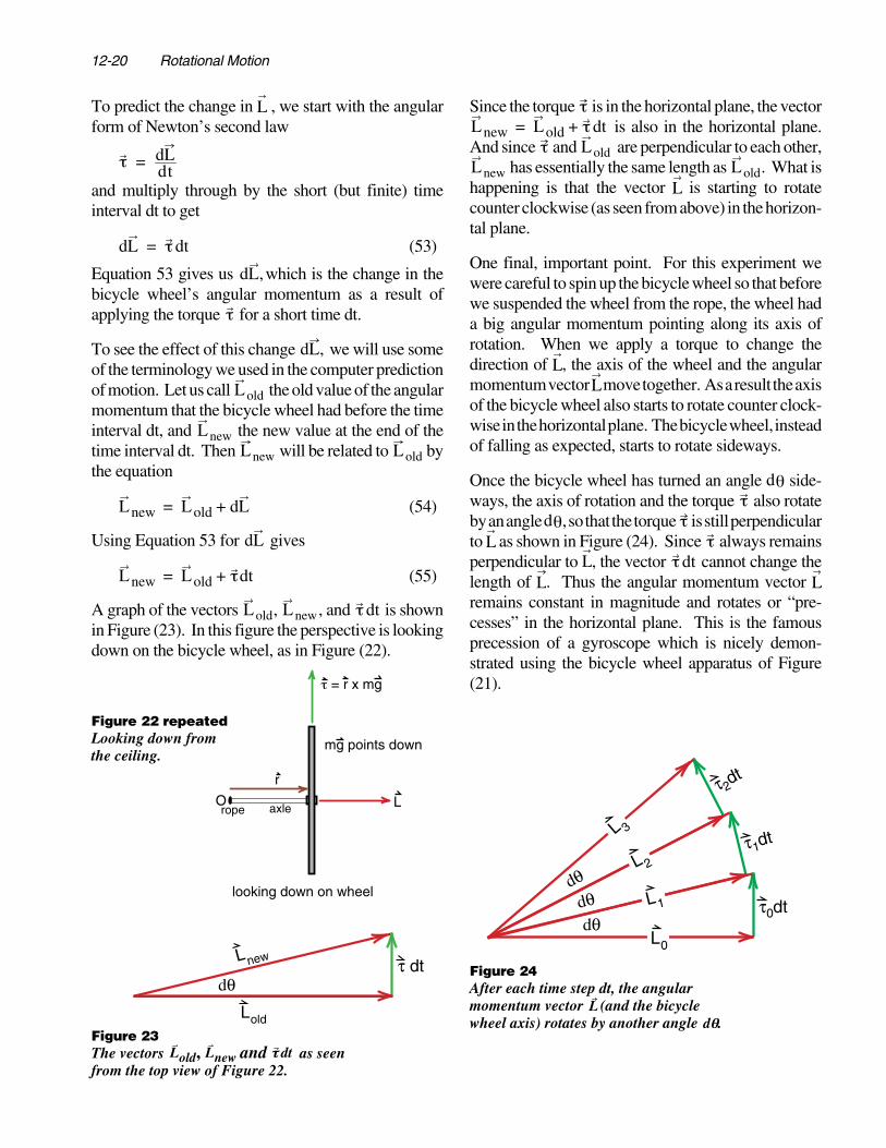
Figure 21Suspend the spinning bicycle wheel by a ropeattached to the axle. The gravitational force mghas a lever arm r about the axis O. This createsa torque ττ = r ×× mg pointing into the paper.
Figure 22Looking down from the ceiling, the vector mgpoints down into the paper and ττ = r ×× mgpoints to the top of the page. In this view wecan see both the vectors L and ττ .
PrecessionWhen we apply the equation τ = dL dtdL dt to a gyro-scope that is already spinning, and apply the torque ina direction that is not parallel to L, the results are not soobvious.
Suppose we get the bicycle wheel spinning rapidly sothat it has a big angular momentum vector L, and thensuspend the bicycle wheel by a rope attached to the endof the axle as shown in Figure (21).
To predict the motion of the spinning wheel, the firststep is to analyze all the external forces acting on it.There is the gravitational force mg which pointsstraight down, and can be considered to be acting at thecenter of mass of the bicycle wheel, which is the centerof the wheel as shown. Then there is the force of therope which acts along the rope as shown. No otherdetectable external forces are acting on our system ofthe spinning wheel.
One thing we know about the force Frope is that it actsat the point labeled O where the rope is tied to the axle.If we take the sum of the torques acting on the bicyclewheel about the suspension point O, then Frope has nolever arm about this point and therefore contributes notorque. The only torque about the suspension point Ois produced by the gravitational force mg whose leverarm is r , the vector going from point O down the axleto the center of the bicycle wheel as shown in Figure(21).
The formula for this gravitational torque τg is
τg = r × mg
torque about point Oproduced by thegravitational forceon the bicycle wheel
(52)
The new feature of the gyroscope problem, which wehave not encountered before, is that the torque τ doesnot point in the same direction as the angular momen-tum L of the bicycle wheel. If we look at Figure (21),point the fingers of our right hand in the direction of thevector r , and curl our fingers in the direction of thevector mg, then our thumb points down into the paper.This is the definition of the direction of the vector crossproduct r × mg. But the angular momentum L of thebicycle wheel points along the axis of the wheel to theright in the plane of the paper. In order to view both theangular momentum vector L and the torque vector τin the same diagram, we can look down on the bicyclewheel from the ceiling as shown in Figure (22).
When we started the wheel spinning, back in Figure(20), the torque τ and angular momentum L pointed inthe same direction, and we had the simple result that thelonger we applied the torque, the more angular mo-mentum we got. Now, with the torque and angularmomentum pointing in different directions as shown inFigure (22), we expect that the torque will cause achange in the direction of the angular momentum.
12-20 Rotational Motion
To predict the change in L , we start with the angularform of Newton’s second law
τ = dLdt
and multiply through by the short (but finite) timeinterval dt to get
dL = τdt (53)
Equation 53 gives us dL,which is the change in thebicycle wheel’s angular momentum as a result ofapplying the torque τ for a short time dt.
To see the effect of this change dL, we will use someof the terminology we used in the computer predictionof motion. Let us call Lold the old value of the angularmomentum that the bicycle wheel had before the timeinterval dt, and Lnew the new value at the end of thetime interval dt. Then Lnew will be related to Lold bythe equation
Lnew = Lold + dL (54)
Using Equation 53 for dL gives
Lnew = Lold + τdt (55)
A graph of the vectors Lold, Lnew, and τdt is shownin Figure (23). In this figure the perspective is lookingdown on the bicycle wheel, as in Figure (22).
Since the torque τ is in the horizontal plane, the vector Lnew = Lold + τdt is also in the horizontal plane.
And since τ and Lold are perpendicular to each other, Lnew has essentially the same length as Lold. What is
happening is that the vector L is starting to rotatecounter clockwise (as seen from above) in the horizon-tal plane.
One final, important point. For this experiment wewere careful to spin up the bicycle wheel so that beforewe suspended the wheel from the rope, the wheel hada big angular momentum pointing along its axis ofrotation. When we apply a torque to change thedirection of L, the axis of the wheel and the angularmomentum vector L move together. As a result the axisof the bicycle wheel also starts to rotate counter clock-wise in the horizontal plane. The bicycle wheel, insteadof falling as expected, starts to rotate sideways.
Once the bicycle wheel has turned an angle dθ side-ways, the axis of rotation and the torque τ also rotateby an angle dθ, so that the torque τ is still perpendicularto L as shown in Figure (24). Since τ always remainsperpendicular to L, the vector τdt cannot change thelength of L. Thus the angular momentum vector Lremains constant in magnitude and rotates or “pre-cesses” in the horizontal plane. This is the famousprecession of a gyroscope which is nicely demon-strated using the bicycle wheel apparatus of Figure(21).
newL
Lold
dθτ dt
Figure 23The vectors Lold, Lnew and ττ dt as seenfrom the top view of Figure 22.
rope
r
LOaxle
τ = r x mg
mg points down
looking down on wheel
Figure 22 repeatedLooking down fromthe ceiling.
L0
L1
L 2
L 3
0
1
2
τ dtdθ
τ dt
dθ
τ dt
dθ
Figure 24After each time step dt, the angularmomentum vector L (and the bicyclewheel axis) rotates by another angle dθθ.

12-21
To calculate the rate of precession we note fromFigures (23) or (24) that the angle dθ is given by
dθ = τdtL (56)
where we use the fact that τdt is a very short length, andthus sin dθ and dθ are equivalent. Dividing bothsides of Equation 56 through by dt, we get
dθdt
= τL (57)
But dθ/dt is just the angular velocity of precession,measured in radians per second. Calling this preces-sional velocity Ωprecession(Ω is just a capital ω“omega”), we get
Ωprecession =τL
precessionalangular velocityof a gyroscope
(58)
Exercise 9A bicycle wheel of mass m, radius R, is spun up to anangular velocity ω. It is then suspended on an axle oflength r as shown in Figure (21). Calculate
(a) the angular momentum L of the bicycle wheel.
(b) the angular velocity of precession.
(c) the time it takes the wheel to precess around once(the period of precession). [You should be able toobtain the period of precession from the angularvelocity of precession by dimensional analysis.]
(d) a bicycle wheel of total mass 1kg and radius 40cm,is spun up to a frequency f = 2πω = 10 cycles/sec. Thehandle is 30cm long. What is the period of precessionin seconds? Does the result depend on the mass of thebicycle wheel?
If you try the bicycle wheel demonstration that wediscussed, the results come out close to the prediction.Instead of falling as one might expect, the wheelprecesses horizontally as predicted. There is a slightdrop when you let go of the wheel, which can becompensated for by releasing the wheel at a slightupward angle.
If you look at the motion of the wheel carefully, or studythe motion of other gyroscopes (particularly the airbearing gyroscope often used in physics lectures) youwill observe that the axis of the wheel bobs up anddown slightly as it goes around. This bobbing, orepicycle like motion, is called nutation. We did notpredict this nutation because we made the approxima-tion that the axis of the wheel exactly follows theangular momentum vector. This approximation is verygood if the gyroscope is spinning rapidly but not verygood if L is small. Suppose, for example we release thewheel without spinning it. Then it simply falls. It startsto rotate, but along a different axis. As it starts to fallit gains angular momentum in the direction of τ . Amore accurate analysis of the motion of the gyroscopecan become fairly complex. But as long as the gyro-scope is spinning fast enough so that the axis moveswith L , we get the simple and important results dis-cussed above.
12-22 Rotational Motion
APPENDIXMoment of Inertia andRotational Kinetic EnergyIn the main part of the text, we briefly discussedmoment of inertia as the angular analogy to mass in theformula for angular momentum. As linear momentump of an object is its mass m times its linear velocity v
p = mv linear momentum (A1)
the angular momentum is the angular mass ormoment of inertia I time the angular velocity ω
= Iω angular momentum (A2)
In the simple case of a bicycle wheel, where all the massis essentially out at a distance (r) from the axis of thewheel, the moment of inertia about the axis is
I = Mr2 moment of inertia
of a bicycle wheel (A3)
where M is the mass of the wheel.
When the mass of an object is not all concentrated outat a single distance (r) from the axis, then we have tocalculate the moment of inertia of individual parts ofthe object that are at different radii r, and tie together thevarious pieces to get the total moment of inertia. Thisusually involves an integration, like the one we did inEquations 21 through 23 to calculate the moment ofinertia of a solid cylinder.
For topics to be discussed later in the text, the earlierdiscussion of moment of inertia is all we need. Butthere are topics, such as rotational kinetic energy and itsconnection to moment of inertia, which are both inter-esting, and can be easily tested in both lecture demon-strations and laboratory exercises. We will discussthese topics here.
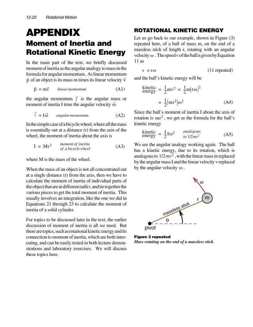
ROTATIONAL KINETIC ENERGYLet us go back to our example, shown in Figure (3)repeated here, of a ball of mass m, on the end of amassless stick of length r, rotating with an angularvelocity ω . The speed v of the ball is given by Equation11 as
v = rω (11 repeated)
and the ball’s kinetic energy will be
kineticenergy = 1
2mv2 = 12m rω 2
= 12 mr2 ω2 (A4)
Since the ball’s moment of inertia I about the axis ofrotation is mr2 , we get as the formula for the ball’skinetic energy
kineticenergy = 1
2 Iω2 analogousto 1/2mv2 (A5)
We see the angular analogy working again. The ballhas a kinetic energy, due to its rotation, which isanalogous to 1/2mv2 , with the linear mass m replacedby the angular mass I and the linear velocity v replacedby the angular velocity ω .
m
θ
r
pivot
ω
massless stick
Figure 3 repeatedMass rotating on the end of a massless stick.

12-23
If we have a bicycle wheel of mass M and radius rrotating at an angular velocity ω, we can think of thewheel as being made up of a collection of masses on theends of rods as shown in Figure (6) repeated here. Foreach individual mass m i , the kinetic energy is 1/2 m iv
2
where v = rω is the same for all the masses. Thus thetotal kinetic energy is
kinetic energyof bicycle wheel
= 12 m ir
2ω2Σi
= 12 r2ω2 m iΣ
i
= 12 r2ω2M
where the sum of the masses m iΣ is just the mass Mof the wheel. The result can now be written
kinetic energyof bicycle wheel
= 12 Mr2 ω2
= 12 Iω2 (A6)
If we call Mr 2 the angular mass, or moment of inertiaI of the bicycle wheel, we again get the formula
1 21 2 Iω2 for kinetic energy of the wheel. Thus we seethat, in calculating this angular mass or moment ofinertia, it does not make any difference whether themass is concentrated at one point as in Figure (3), orspread out as in Figure (6). The only criterion is that themass or masses all be out at the same distance r from theaxis of rotation.
In most of our examples we will consider objects likebicycle wheels or hollow cylinders where the mass isessentially all at a distance r from the axis of rotation,and we can use the formula Mr 2 for the moment ofinertia. But often the mass is spread out over differentradii and we have to calculate the angular mass. Anexample is a rotating shaft shown back in Figure (9),where the mass extends from the center where r = 0 outto the outside radius r = R.
Suppose we have an arbitrarily shaped object rotatingan angular velocity ω about some axis, as shown inFigure (A1). To find the moment of inertia, we willcalculate the kinetic energy of rotation and equate thatto 1/2Iω2 to obtain the formula for I. To do this weconceptually break the object into many small masses
dm i located a distance ri from the axis of rotation asshown. Each dmi will have a speed vi = riω , and thusa kinetic energy
kinetic energyof object
= 12m ivi
2Σi
= 12m iri
2ω2Σi
= 12ω2 m ir i
2Σi
= 12ω2 I (A7)
From Equation A7, we see that the general formula formoment of inertia is
I = m ir i
2Σi
(A8)
Figure 6 repeatedBicycle wheel as a collection of masseson the end of massless rods.
ω
r
axis ofrotation
mi
ir
ω
Figure A1Calculating the moment of inertia ofan object about the axis of rotation.

12-24 Rotational Motion
In Example 1, Equations 21 through 23, we showedyou how to calculate the moment of inertia of a solidcylinder about its axis of symmetry. In that example webroke the cylinder up into a series of concentric shellsof radius ri and mass dmi , calculated the moment ofinertia of each shell dmi ri
2 , and summed the resultsas required by Equation A7. As in most cases where wecalculate a moment of inertia, the sum is turned into anintegral.
In Exercise 3 which followed Example 1, we had youcalculate the moment of inertia, about its axis ofsymmetry, of a hollow thick-walled cylinder. Thecalculation was essentially the same as the one we didin Example 1, except that you had to change the limitsof integration. The following exercise gives you morepractice calculating moments of inertia, and shows youwhat happens when you change the axis about whichthe moment of inertia is calculated.
Exercise A1
Consider a uniform rod of mass M and length L asshown in Figure (A2).
a) calculate the moment of inertia of the rod about thecenter axis, labeled axis 1 in Figure (A2).
b) calculate the moment of inertia of the rod about anaxis that goes through the end of the rod, axis 2 in Figure(A2). About which axis is the moment of inertia greater?Explain why.
COMBINEDTRANSLATION AND ROTATIONIn our discussion of the motion of a system of particles,we saw that the motion was much easier to understandif we focused our attention on the motion of the centerof mass of the system. The simple feature of the motionof the center of mass, was that the effects of all internalforces cancelled. The center of mass moved as if it werea point particle of mass M, equal to the total mass ofthe system, subject to a force F equal to the vector sumof all the external forces acting on the object.
When the system is a rigid object, we have a furthersimplification. The motion can then be described as themotion of the center of mass, plus rotation about thecenter of mass. To see that you can do this, imagine thatyou go to a coordinate system that moves with theobject’s center of mass. In that coordinate system, theobject’s center of mass point is at rest, and the onlything a rigid solid object can do is rotate about thatpoint.
A key advantage of viewing the motion of a rigid objectthis way is that the kinetic energy of a moving, rotating,solid object is simply the kinetic energy of the center ofmass motion plus the kinetic energy of rotation. Ex-plicitly, if an object has a total mass M, and a momentof inertia Icom about the center of mass (parallel to theaxis of rotation of the object) then the formula for thekinetic energy of the object is
kinetic energyof moving androtating object
= 12 MVcom
2 + 12 I com ω2 (A9)
where Vcom is the velocity of the center of mass and ωthe angular velocity of rotation about the center ofmass.
More important is the idea that motion can be separatedinto the motion of the center of mass plus rotation aboutthe center of mass. To emphasize the usefulness of thisconcept, we will first consider an example that caneasily be studied in the laboratory or at home, and thengo through the proof of the equation.
axis 1axis 2
L
m
Figure A2Calculating the moment of inertia of a long thin rod.

12-25
Example—Objects RollingDown an Inclined PlaneSuppose we start with a cylindrical object at the top ofan inclined plane as shown in Figure (A3), and measurethe time the cylinder takes to roll down the plane. Sincewe do not have to worry about friction for a rollingobject, we can use conservation of energy to analyzethe motion.
If the cylinder rolls down so that its height decreases byh as shown, then the loss of gravitational potentialenergy is mgh. Equating this to the kinetic energygained gives
mgh =
12
m vcom2 +
12
Iω2
(A10)
where m is the mass of the cylinder, vcom the speed ofthe axis of the cylinder, I the moment of inertia aboutthe axis and ω the angular velocity.
If the cylinder rolls without slipping, there is a simplerelationship between vcom and ω. We are picturing therolling cylinder as having two kinds of motion—translation and rotation. The velocity of any part of thecylinder is the vector sum of vcom plus the velocity dueto rotation.
At the point where the cylinder touches the inclinedplane, the rotational velocity has a magnitude vrot = ω r,and is directed back up the plane as shown in Figure(15). If the cylinder is rolling without slipping, thevelocity of the cylinder at the point of contact must bezero, thus we have
vcom + ω r = 0 rolling without
slipping (A11)
Thus we get for magnitudes
ωr = vcom ; ω = vcom /r (A12)
Using Equation A12 in A10 gives
mgh =
12
mvcom2 +
12
Ivcom
2
r2
=12
m +I
r2vcom
2 (A13)
Let us take a look at what is happening physically as thecylinder rolls down the plane. In our earlier analysisof a block sliding without friction down the plane, allthe gravitational potential energy mgh went into ki-netic energy 1/2 mvcom
2 . Now for a rolling object, thegravitational potential has to be shared between thekinetic energy of translation 1/2 mvcom
2 and the kineticenergy of rotation 1/2 Iω2. The greater the moment ofinertia I, the more energy that goes into rotation, the lessavailable for translation, and the slower the object rollsdown the plane.
In our discussion of moments of inertia, we saw that fortwo cylinders of equal mass, the hollow thin-walledcylinder had twice the moment of inertia as the solidone. Thus if you roll a hollow and a solid cylinder downthe plane, the solid cylinder will travel faster becauseless gravitational potential energy goes into the kineticenergy of rotation. You get to figure out how muchfaster in Exercise A2.
h
θ
vcom ωrr
ω
Figure A3Calculating the speed of an object rolling down a plane.
Figure A4The velocity at the point of contact is the sum of thecenter of mass velocity and the rotational velocity.This sum must be zero if there is no slipping.

12-26 Rotational Motion
Before you work Exercise A2, think about this ques-tion. The technician who sets up our lecture demon-strations has a metal sphere, and does not know for surewhether the sphere is solid or hollow. (It could be asolid sphere made of a light metal, or a hollow spheremade from a more dense metal.) How could you findout if the sphere is solid or hollow?
Exercise A2You roll various objects down the inclined plane shownin Figure (A3).
(a) a thin walled hollow cylinder
(b) a solid cylinder
(c) a thin walled sphere
(d) a solid sphere
and for comparison, you also slide a frictionless blockdown the plane:
(e) a frictionless block
For each of these, calculate the speed vcom after theobject has descended a distance h. (It is easy to do allcases of this problem by writing the object’s moment ofinertia in the form I = αMR2,, where α = 1 for the hollowcylinder, 1/2 for the solid cylinder, etc.) What value of αshould you use for the sliding block?
Writing your results in the form vcom =β 2gh summa-rize your results in a table giving the value of β in eachcase. (β = 1 for the sliding block, and is less than 1for all other examples.)
Exercise A3 A Potential Lab Experiment
In Exercise A2 you calculated the speed vcom of variousobjects after they had descended a distance h. A blocksliding without friction has a speed v given by
mgh =1/2 mv2 , or v = 2gh . The rolling objects weremoving slower when they got to the bottom. For allheights, however, the speed of a rolling object is slowerthan the speed of the sliding block by the same constantfactor. Thus the rolling objects moved down the planewith constant acceleration, but less acceleration thanthe sliding block. It is as if the acceleration due to gravitywere reduced from the usual value g. Using this idea,and the results of Exercise A2, predict how long each ofthe rolling objects takes to travel down the plane. Thisprediction can be tested with a stop watch.
PROOF OF THEKINETIC ENERGY THEOREMWe are now ready to prove the kinetic energy theoremfor rotational motion. If we have an object that isrotating while it moves through space, its total kineticenergy is the sum of the kinetic energy of the center ofmass motion plus the kinetic energy of rotationalmotion about the center of mass. The proof is a bitformal, but shows what you can do by working withvector equations.
Consider a solid object, shown in Figure (A5), that ismoving and rotating. Let Rcombe the coordinatevector of the center of mass of the object. We will thinkof the object as being composed of many small masses
m i which are located at Ri in our coordinate system,and a displacement r i from the center of mass asshown. As we can see from Figure (A5), the vectors
Rcom, Ri and r i are related by the vector equation
Ri = Rcom + ri (A14)
We can obtain an equation for the velocity of the smallmass mi by differentiating Equation A14 with respectto time
dRidt
=dRcom
dt+
d ridt
(A15)
mi
comRi
Rcom
ir
Figure A5Analyzing the motion of a small piece of an object.
12-27
which can be written in the form
Vi = Vcom + vi (A16)
where Vi = dRi /dt is the velocity of mi in our coordi-nate system, Vcom = dRcom/dt is the velocity of thecenter of mass of the object, and vi = dr i
/dt is thevelocity of m i in a coordinate system that is movingwith the center of mass of the object.
The kinetic energy of the small mass m i is
12
m iVi2 = 1
2m i Vi • Vi
= 12
m i Vcom + vi • Vcom + vi
= 12
m i Vcom2 + 2Vcom • vi + vi
2
= 12
m iVcom2 + 1
2mivi
2 + miVcom • vi
(A17)The total kinetic energy of the object is the sum of thekinetic energy of all the small pieces mi
totalkineticenergy
= 12
miVi2Σ
i
= 12
Vcom2 miΣ
i+ 1
2mivi
2Σi
+ Vcom • miviΣi
(A18)In two of the terms, we could take the common factor
Vcom outside the sum.
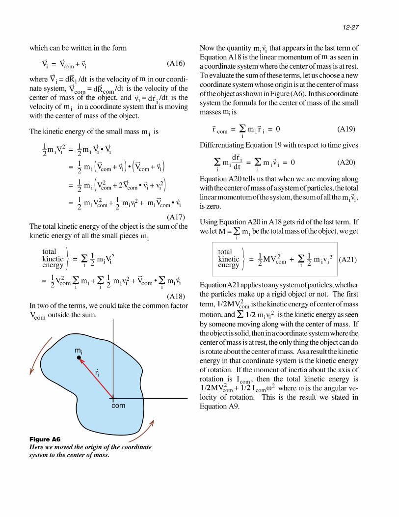
Now the quantity mivi that appears in the last term ofEquation A18 is the linear momentum of mi as seen ina coordinate system where the center of mass is at rest.To evaluate the sum of these terms, let us choose a newcoordinate system whose origin is at the center of massof the object as shown in Figure (A6). In this coordinatesystem the formula for the center of mass of the smallmasses mi is
r com = m i r iΣi
= 0 (A19)
Differentiating Equation 19 with respect to time gives
mi
dr idtΣ
i= m iv iΣ
i= 0 (A20)
Equation A20 tells us that when we are moving alongwith the center of mass of a system of particles, the totallinear momentum of the system, the sum of all the mivi,is zero.
Using Equation A20 in A18 gets rid of the last term. Ifwe let M = miΣ
i be the total mass of the object, we get
totalkineticenergy
= 12 MVcom
2 + 12 m ivi
2Σi
(A21)
Equation A21 applies to any system of particles, whetherthe particles make up a rigid object or not. The firstterm, 1 21 2MVcom
2 is the kinetic energy of center of massmotion, and 1 21 2 mivi
2Σ is the kinetic energy as seenby someone moving along with the center of mass. Ifthe object is solid, then in a coordinate system where thecenter of mass is at rest, the only thing the object can dois rotate about the center of mass. As a result the kineticenergy in that coordinate system is the kinetic energyof rotation. If the moment of inertia about the axis ofrotation is Icom , then the total kinetic energy is
1 21 2MVcom2 + 1 21 2 Icomω
2 where ω is the angular ve-locity of rotation. This is the result we stated inEquation A9.
mi
com
ir
Figure A6Here we moved the origin of the coordinatesystem to the center of mass.