Embed Size (px)
Citation preview

-- RI64 726 MNIMIZING E NF N VEGUIDE LOSSES(U) ROME AIR DEVELOF ET 1/1CENTER GRIFFISS RFD MY E N GILBERTSON DEC 65
6RlA64 RDC-TR-95-223
UNCLASSIFIED F/B 911 U.
111111 11111111nmmhhhEohhEohhnomohEmhhhhlmmhEMMhEMhEMhhhE

7.~~ K717
r
1 ' 1. M
J~flJI.2W32 2u .2l111111.25ii11,. '
MICROCOPY RESOLUTION TEST CHART
k. .
a.-°
I-:
-. .:.*
a~. - . . -. -
Sa. a -a. -~ :

(Nr % RADC-TR-85-223*In-House Report
December 1985
S.4
< MINIMIZING EHF WAVEGUIDE LOSSES
Edward W. Gilbertson, Captain, USAF
APPROVED FOR PUBLIC RELEASE; DISTRIBUTION UNLIMITED
!, S I
KE,-( . *... .
ROME AIR DEVELOPMENT CENTER- Air Force Systems Command
Griffiss Air Force Base, NY 13441-5700 -
86 2 2.6 034
* 4
. .. . .. - ( : .: :

This report has been reviewed bv the RAPC Public Affairs Office (PA) andis releasable to the National Technical Information Service (NTIS). At NTISit will be releasable to the general public, including foreign nations.
RNDC-TR-S5---3 has been reviewed and is approved for publication. - .
APPROVED:
DONALD SPECTOR, Acting Ass't Chief
Communications Transmission BranchCommunications Division
APP ROVED: Q Q z .!i7ILLIAM 13. NILES, Colonel, USAFChief, Communications Division
FOR THE COMMANDER: A , °
RICHARD W. POULIOTPlans Office
If your address has chan~ed or if you wish to be removed from the RADCmailing list, or if the addressee is no longer employed by your organization,please notify RADC (DCCR) Griffiss AFB NY 13441-5700. This will assist us inmaintaining a current mailing list. S
Do not return copies of this report unless contractual obligations or noticeson a specific document requires that it be returned.
i iji 1.7 -.. ll. I ii: i. Z i jj~i .i~i ..- ".0

-~~~ - -' . -- ~I E
("XIAkSSTFIED)SL RI"CLASYr A'C(_N 01' H', P'It
REPORT DOCUMENTATION PAGE*'a REPORT SEC)RTy CLASS.EICA ON
1b RESTRICTIVE MAARKNGS
* UNCI.ASSIFIED N/ A'a SECiUR Ty CLA S (AT'ON AJTnORiTY 3 DISTRIBUTION AVALPABILITV OjF REPORT% /A Approved " or pub i c reT ea se;
'b OCASFCTODONANOC-DEdistr 1but ion unl imitedN/A ____________________
4 PR;OPM'Ni3 ORG3ANIZTATION RE PORT NUMBEWISI 5 MONITORING OQGANIZA'ON REPORT NUMBLRtSI
RADC-TR-85-2213 X/ A9
6a aAM 0NAN'SRflt R(%jZA7% 6:, OF NT0I05 Nu ORGANIZAV.ONf (It 1iplrcable)
RoeAirDeveopmnt Centejffi CCR N/A
*b< aDDESF 55City, State anid .'IP Code) 7b ADORE 55 City State and ZIP Code)
Griffiss M(0 '71 1 1-4.1-570n) N/A
Ba NME 1 ':IJ)%G PO-0WIN,; ti (" IF * BOL 3 POC AEMEN' NSTRUIVMENT DINTIF'CATION NJMBER
D nO (,q i ej Z)PCode)0 SOuRCE OP FUjNDNC., NU)MBERSPORAM PRJC AKWORK UNIT
Grifs AB ' 141-5700 pvyNI NO NO NO ACCESSION NO . I________________________________ 6_3431F 1227 00 03
(I,'cudeS.wy Cas (Jin
MT NIMI ZNC F11F (sAVFG1UT F. LOSSES
* 2 '1PESONAL A. 'iOR(S)
Edward (4. Gilbertson, Capt, USAF
3a 'YPE OF REPORT 3b TbI'ME COVERED 14 DATE OF REPORT (Year Monh ay15PGE COUNTT n-House RMTODecember 1985 846 SUPPLEMEN'ARY NOTATION
*N/A .
7 (ITSAl CODE1 II SUBJECT TERMS (Continue On reverse of necessary and identify by block number)IL _Lti e SB CROtUP Waveguide Oversized Waveguide Attenuation(19 Cl ~ -EHF Overmoded Waveguide
Dielectric Wavegulde Circular Waveguide9 ABSTRACT IContinue on reverse it necessary and identity by block number)To minimize RF power transmission losses at high frequencies, rectangular waveguide hasbecome the standard transmission medium. At EHF frequencies, rectangular waveguide attenua-tion rises to unacceptably hi!-,h levels. To minimize waveguide loss, length is minimized.Where this is not possible, a varietv of alternatives exist, each having lower attenuationthan standard rectangular waveguide and each with its own advantages and limitations. Squarecircular (modes TF.ll and TE0 1), oversized rectangular, oversized circular (modes TEll andTF01 ), and dielectric waveguides are addressed and categorized according to bendability. By
*choosing the technology with the lowest attenuation which meets the installation's bendabilitrequirements, the optimum transmission method can be determined. Attenuations are calculated *
for comparison at 44 Gli., but the discussion Is general enough to hold throughout the ERFfrequency range.
2') D)IST~iIJTION AVAIJABILJT' OF ABSTRACT 21 ABSTRACT SECURITY CLASSIFICArION %
LUUNCLASSIFIEDUNLIMITED 0l SAME AS RPT CDlIC USERS UNCLASSIFIED .*
2a N4AME 01 RFSPONSIBE 'NDIVIOIJAL 22b TELEPH-ONE (include Area Code) 122c OFFICE SYMBOL . .,.4
Edward W. Gilbertson, Capt, USAP (315) 330-3091 RAflC (DCCR )JC
DO FORM 1473, 84 MAR 83 APR edition may be used urtil exhausted SECURSITY CLASSIFICATION OF -HIS PAGE - * ~'z~All other editions are obsolete -
UINCLASSIFIED
'-I.. '
- .. .

ACKNOWLEDGEMENTS
I would like to acknowledge the help and cooperation of fellow RADCengineers, Lincoln Lab engineers, Naval engineers of NUSC, NESEA, NOSC, andthe Norfolk Naval Shipyard/Combat Systems Office. I would also Like toat-knowledge the assistance provided by the countless contractor representatives-and engineers contacted. I would particularly like to acknowledge the help ofMr. Mike Devan of the Naval Ocean Systems Center, who has provided me withmuch of the Information presented here and many poi nts of contact. -4
Acc-'-

2.GENE- . ..... . .. 3
.- 7
TABLE OF CONTENTS .-.......... ...
4. INTRODUCTION AND SCOPE .......................................... -...1.1 INTAODUCTION. ........................................ ."1.2 SCOPE ....................................................... 2
2. WAVEGUIDES - GENERAL .......................................... ...
44. THE TECHNOLOGIES.. MDI......................................... 134.1 RECTANGULAR WAVEGUIDE - THE STANDARD ..................... 13 ""
4.2 CIRCULAR WAVEGUIDE .................................... 16
4.2.1 TE 1 MODE, ........................................... 6194.2.1.1 MODE TEll DISCUSSION ......................... 19
4.2.1.2 MODE TE11 COMPONENTS ....................... 214.2.1.2.1 COMPONENT AVAILABILITY ............ 214.2.1.2.2 COMPONENT DESCRIPTIONS ............. 23 '
4.2.2 TE0 1 MODE, THE "LOW LOSS" MODE........................26 4.2.2.1 MODE TE 1 DISCUSSION........................... 264.2.2.2 MODE TEoN COMPONENTS........................... 28
4.2.2.2. COMPONENT AVAILABILITY................. 284.2.2.2.2 COMPONENT DESCRIPTIONS ................. 30 -" - - -"""4.2.2.2.3 OPERATIONAL EXPERIENCE...............37 ' '-,'':'-
4.3 OVERSIZED WAVEGUIDES ....................................... 3943.1 OVERSIZED RECTANGULAR .................................. 2414.3.2 OESIZED CIRCULAR. .. ................................ .4
4.4 DIELECTRIC WAVEGUIDE................................... 46
5. THE DECISION PROCESS...............................5
5.1 DESIGN CONSTRAINTS......................................... 52 k 4. .5.1.1 INSTALLATION DERIVED..................................52 ,.-.-.-.-$''
5• ..2 TECHNOLOGY INHERENT..................................55 ".x'--.-'""
5.2 THE BOTTOM LINE: THE CHOICE FOR LOWEST ATTENUATION ....... 555.2.1 BENDABILITY, RUN LENGTH, & ATTENUATION ............... 555.2.2 EXPECTED ATTENUATIONS ............................. 58
5.2.3 CONCLUSION & RECOMMENDATIONS . .................. 61 -
APPENDIX I ..................................................... 63ABRIDGED VERSION OF MIL-W-23068
APPENDIX 2 ..................................................... 65BIBLIOGRAPHY OF TE01 MODE rU -APPENDIX 3 .................................................... 70DIELECTRIC WAVEGUIDE TEST DATA
'Ii.

LIST OF FIGURES
* FIGURE
* 1. Rectangular waveguide cross section & axes............................1
2. I-Field patterns of waveguide modes................................... 12
I3. Theoretical attenuation charts for rectangular & circular............. 17
4. Attenuation of various modes in 10 cm. copper circular waveguide ... 25
*5. Internally corrugated electroformed bend for Low Loss Mode............31-
16. Waveguide transitions................................................. 33-
7. Rectangular dielectric waveguide...................................... 46
8. Waveguide Attenuation vs. length...................................... 59
LIST OF TABLES
TABLE
U1. Cutoff operating frequencies of waveguides............................ 4
2. Standard rectangular waveguide........................................ 7
3. Attenuations of available technologies................................ 8
D 4. Conductivity of metals at 24 GHz...................................... 14
5. Relative cutoff frequencies for circular waveguide modes.............. 18
*6. Circular waveguide sizes.............................................. 22
7. Technologies arranged in order of attenuations........................ 54
8. Straight wavegtuide attenuations (44 GHz).............................. 57
9. Sample- 20 ft. run from 50 W transmitter............................. 60
iv
~j~Q.':.c.&.~j.:.1 7~j.§ :..;' 1 ~.~%

I S.
SECTION I
INTRODUCTION & SCOPE
1.1 INTRODUCTION
Assume that, for a particular system, both the transmitter and the
antenna(s) have been chosen and that for some reason, the two cannot be
collocated. The next decision is how to interconnect them. At UHF and
some SHF frequencies, coaxial cable is standard. At some SHF and all EHF
frequencies, rectangular waveguide is standard.
Rectangular waveguide losses increase as the frequency range of the
waveguide increases. By EHF frequencies, the waveguide losses which were '
negligible at lower frequencies are now formidable. At 44 GHz, waveguide
losses are 0.25 dB per foot or half power every 12 feet. The foregone -
conclusion to use rectangular waveguide should be reexamined for each
system employing a long run (5 ft or more) of EHF rectangular waveguide.
Specifically, given a particular EHF system, what transmission methods
offer the lowest attenuation but can still satisfy the environmental and
bendability requirements of a given installation. There are several
alternatives available which have lower loss than standard rectangular
waveguide. Some of these are not bendable, some can only make rigid bends,
while still others can be either semirigid or flexible. No matter what
your installation physically requires, lower losses than standard
rectangular waveguide can be realized if the length of the run exceeds a
certain threshold distance (4 ft for 44 GHz).
. A - . -,
L%
.................................................................................

- -.
1.2 SCOPE
Dealing completely with minimizing losses in waveguide at EHF
frequencies could easily fill several volumes. This paper is directed
toward examining alternatives for a 10 to 100W transmitter installed aboard
an aircraft with its antenna(s) located less than 25 ft away. The
attenuation figures shown have been calculated based upon a frequency of 44
GHz. Bends are probably a necessity. Semi-rigid sections are a real world
need caused by the requirement to install manufactured waveguide sections
into aircraft which vary somewhat from airframe to airframe. Flexible
sections may be useful to reduce the stress on the waveguide as the A -
aircraft flexes.
In order of importance, the criteria for comparing transmission
techniques are attenuation, rigid bendability, semi-rigid bendability, and
flexibility. Of these four criteria, the first is desired to be as low as
possible, but the remaining three will be dictated by the particular
aircraft installation. Although these criteria are examined in terms of a
44 GHz installation under 25 ft in length, the transmission methods
discussed are the alternatives available throughout the EHF frequency range
for almost any transmission distance. r -
2 W............ , ... "....
. .. -. - ' . " . .
.- " .. °.-,-.- .-.

'-l -. 7 -77 0V
.V'AVEGUdtES - VNERAL .
There are an intinite number ol modes Dossible in waveguid,-s. Modles
are designated by the shape of the waveguide in whicn they propagate and by
eitner a T~xx or a TMxx designation. Transverse Electric (TExx) waveguideI
niotes are also designated as w ix' ii;11e Transverse Mgei Tx)modes -
are also ;Ex modes. The xx subscriots refer to the electromagnetic
patterns within trie waveguides as tne mode propagates energy through the
4"ho ide
vaveguides general'v have one intended or desired or primary mode of
propagation. This mode transfers the energy. Undesirable modes are any
rnoues whose existence cau~se a noticeable decrease in the energy of the
desired mode. They eitner excessively lose energy in transmission through
the guioe or are g-enerated at the expense of energy from the desired mode
and are or a form not recoverable bjy the transition at the receiving end.
Either way, they are lost energy in transmission and appear as an increase
in waveguide attenuatio0n.
A wave;uiue will propagate a mode if the guide is large enough.
Anotner way if 'Looking at this is tiat any mode will propagate in a
waveguide L! tnP mode S Cut Off frecuencv (fc) is below the frequency being -
propagated. In this way, waveguides act as high pass filters, passing only
tfiose trequer-cies above fc. The waveguide's cut off is extremely sharp,%
nowever, since at tc and below, the attenuation is infinite while at
trl~ouencies; lust 1.15 tinmes 11c, tie waveguide is a usable transmission
~"-1-6r (see Table 1). Since tie c- ot trequency, fc, is a direct function
3**-*
O.

W~WEWI W~U I U'~W.!WJ WE -. -. ~ -. ~
S
I0
~. 0
V C 0'
U
I- S4)
4)
0
-o AV h. CV 00 0* - C
0 VV ~O C - 4)V *.- ~
U U04)
0 4)hi S
- ~; ~.
-. 0hi
I 000
-' I' '442
U
U.U. gOV I* . *0
I -VI
U. 0
II
I 0
S - ,. 'f .**.*'*
r~ -~
4
U 0..
*. *. *. . . . .
- . .

oi t w wa e -,ki I /.t wave .tti d k i ZI i 12 h vi: ry 1 rhport a nt
*, h ve 7 i I ie bi ~s i r II r i i y C u S eO 11 that-l i nd(Itsj r.-i i k e
t) or,) ,iat t a t o r t ea r t I i r C(Lto~ I L tLr o( ijuenei i e s wi n I u t he de s i r td d~
!Iopa gates Well aIbove it t Ic. Ln tn i S way, uindes ired imodes: arke ,rt at ti
it llldtC.1.. i Lc the desi red irode propagates wi th re lati ve y LOW
itt otL IMn. StLanda rd s I 4,od wave~u I de!s, t Iere fore ,have a rmode ti I t r i ng
o Ie t .nd c an o t tf n be used wi t lout a se parat e modle fi 1 te r
iiit- Liar e r t te wavg iiui ce the lowcr its Attenuoat ion. iiowe ver, as Lt1,-
wav -Iri (de i satrade larger , the wavegnnii de 's sensi ti vi ti to i .,por teect i ons ana
taie mi,iihber of hi jher orde 2red modes whi cii are able to propagate i rreases .
1) o jicat i on Ltrou~h a p r tec t ly s trai ,h ,e rbofec t iy sarcaith, and ci tner
j~ortI c t iv reCtang ula r or oc r tee tlIy c ircu lar wa v,,_ui de -.ou Id acki eve thie
L t1O 'Lt 1 ca L. Lttenont i on ot TFab le I imiperfectioens, however, coni-verL a
r .. ct ni ifo trio enor.gV Lroi-; the desi red -node into any otner )ropa ,ation,
.- ,S 5itI C ii are pos s ible i n the gui de. When the desi redI mokie i s
fl trj,nmitioneu oack out ot the guide at the receiving end, undesi reabie mces -
- .qear as intc reased wavegu iuc attenuat ion because they do not t r ansition cut
0r tL ike gu du andl are lost energy.
I ue sc wave .,u ide iri,.pe r fec t ious introluce i nduc tive or c apacitive
:.ii into the ui de's attenuati on.. As trie 6ui ne'" s atteiiuati on
ns csrthese reactive components have a greater and greater effect.
I .- rico:T--rtO the 6enierati on of lhigher ordered undesireable modes,
',lin., in,h V.S~R' s, and hi gh attenuation are all erfects. This can be
iiK,,red to ;t tuned circuit. Two reactive comp-onents separated by a low. -
)pedance connection can tf.orm a resonant circuit wi th a high ~.Addi n;
Atteniuation in series helps to dampen this high n~resonant circui t andi
5
mm
....................................7

-cir h, i lt oI t i rcsonant osc i I lations generated. In low S
at I ,ua I n wav,'<,u id thl dampen i ng of the waveguide "Q" for undesirable
v:,,s ni v be doni. by add i ng mode ri Iters in series with the waveguide or by
nropcrly sizing the waveguide. Either of these techniques selectively .
attenuates the undesirable propagation modes while passing the desired
niode. Anotner possible way to reduce the resonance Q is to decrease the
ma;nitude of the reactances, themselves. By eliminating bends from the S
waveguide, the reactances will be reduced.
6
-% .- %°.-•

• - , , , " .' .
* 4
)" 1 an
lg/* I 0- 0 x 0 T
11A iinl V1 L XIKAIi 9
"F X
ll)' -7t
tA %
0, o o o 0 , 0,-00
0 g o 0 0 0 0 0
• - - - - 0 0 0 0 0 00 " o; "
""~~~ M -- '
-- , 0 o o 6 0 01C, . ,-0-. .-.. . -
,.o"030 S 0 0 S- . ' -.<,
* - - 0 0 o 0- 0 C 4. ._ _ _.__ _ _ _ _ _ _ _ _ _ _ _ _ _
f/ 3 . . . o........ . . . . -.
cc - JA~
1w) 0 0 4*I,,O 00 0 .0 0 4 0
Pur --aAeIm~Iu 9M V1 E9 er E 9 E

E-4 E-4j E-pE 4 n U
94 0Z 44ww
00C
00
4o Wx >~ 41 -- -4 > ~ >' >-4
V Vpm 0 4
0. Ln U4-'40 0
oo o to :0
C'. uC 0o
14 4-4 4 0. 41 .,4 C
cc, 41 q ,
0 C r-4 0 n U4 :4 LJ4 C' 4 0 0
0I -4- 00 00
-44
0c cc
Cu ~ -

SECTION 3p 0
ATTENUATION, THE PRIMARY CRITERION
Z- C°
"- ", "''
Attenuation is the primary criterion. Since rectangular waveguide
exists, is easily available, and works reliably at EHF frequencies, the
technologies we consider must perform better than standard rectangular
waveguide. Table 2 shows a portion of a standard rectangular waveguide .
table. 44 GHz transmission utilizes WR 22 waveguide with an attenuation of
0.23 dB per foot (theoretical). Actual high conductivity copper waveguide
will measure about 15 % higher than theoretical or about 0.26 dB per foot
at 44 GHz. By eliminating all transmission technologies which cannot
achieve attenuations less than 0.26 dB per foot, we can make standard
rectangular waveguide performance the acceptance standard. This narrows
the field under consideration as shown in Table 3 to circular waveguide,
square waveguide, oversized waveguide (both circular and rectangular), and
dielectric waveguide. These will be addressed in turn, but first I would L ....
like to address several of the deleted technologies.
Several of the technologies deleted in Table 3 are self-explanatory.
Microstrip, finline, and stripline are integrated circuit techniques which r -
* are far too lossy when scaled up from micro to macro scale. Coaxial cables -
• are too lossy above 40 GHz and some, such as helical cables, are not made
above 20 GHz. Likewise, elliptical waveguide is not manufactured for use rg_.above 20 GHz either.
Dielectric filled waveguide is basically a waveguide which has been
filled with a dielectric material. It's losses must be greater than the
losses of an unfilled waveguide because waveguide attenuation is the sum of• ,..--.->. .-. ,
9
% %.
(... V P.V .~. ~ Cj. . .. %

E - -
- . . -; 1 - v - , . . w a -- '' " - - r r 4, - r - .• * . 4r .T - - . wo - w v - l -- .
conductive waveguide losses and bulk dielectric losses. The bulk --
dielectric losses must increase when filling the waveguide with any
*dielectric material. In addition, filling the waveguide with dielectric
%. . -
i . ~~'. - . - - .* %A
must cause the size of the waveguide to decrease because of the slowing of
electromagnetic propagation within the guide caused by the dielectric.
This decrease in waveguide size causes a corresponding increase in the
conductive losses in the guide, so both the dielectric bulk losses and
conductive losses will increase when dielectric filling is added. The only
advantage to filling a waveguide with a dielectric is in increasing its
power handling capacity. Since none of the technologies of interest which .
remain from Table 3 are limited by their power handling capacity, for our
purposes, dielectric filling offers us no advantages.
7.
1 % . .. •*. *..*

.~~~~. . .0 ..

Rectangular TI10 Mode Rectangular TE01 Mode 9 14
CirCUlar TEII Mode Circular TE0 1 Mode Circular TE02 Mode
("Low Loss Mode")
ISDISTORTIONS CAUSED BY ELLIPTICITIES IN CIRCULAR GUIDES
TEO, even
TEl1 odd
Figure 2: E-Field Patterns of Waveguide Modes
12

i%-
SECTION 4
THE TECHNOLOGIES
4.1 RECTANGULAR WAVEGUIDE - tHE STANDARD
The standard way to connect EHF and even most SHF equipment is to use
' rectangular waveguide. Coaxial cable is also an alternative (especially at
SLIF frequencies), but when low transmission line loss or high power
transmission are required, the use of coaxial cable becomes unsatisfactory.
At SHF frequencies, waveguide is practically without attenuation, but as
coiununications frequencies increase into the EHF range, even the .
comparatively low attenuation of rectangular waveguide becomes formidable.
' •table 2 shows some standard rectangular waveguide sizes and
characteristics. There are almost 30 standard sizes with frequency ranges
distributed between 750 MHz to 325 GHz. For 44 GHz operation, the stanG .d -. --
sized waveguide is designated WR 22. The shape and axes of standard .
daveguide are as shown in Figure 1 with the ratio of a:b being 2:1. This
ratio determines the operating bandwidth of the waveguide. Energy is -
propagated through rectangular waveguide using the rectangular Transverse
Electric (TE) node TE10 whicn is shown in Figure 2. L "
Attenuation in any waveguide is dependent upon the conductivity of the
. i;etal forming the interior surface ot the waveguide. This conductivity of -
metal is not necessarily the same as the conductivity of metals found in
• * most tables of electrical conductivity. Aost tables show values for.'.' •~~9. .. : , "°
electrical conductivity which are measured using direct current (d.c.). .e
Waveguides are operated at frequencies measuring in the GHz. At these
13
• -
". -.' ...''" .' ..''''. .' . ""'. . - - - . - " ""e "-"-.. ." ".-"-.".. .". .. " . -' . '° - " " .. .".. . . .. -, - ."' ''°'. ' ''' ,. -. ," "' '

rff. cond. v,at
Material X =1.25 m DC cond. a in 10- znhos m .-
in
.......rn~ ...... __ 1 .nls'7 & 3.25 (measured)
4SAlloy kiahn- ufc)... 1.54 1.6(esrd
Yelliow% (80-20) drawn waveguide 1 1.45 1.57 (measured)Recd (85-15) drawni %%aveguide. 2.22Yellow round dlrawn tu1ing ........ 1 .36 1 .56 (Eshhach) L
Yr.hltow (S0-20) (macnhin~ed surface) 1 .17 1 .57 (Kshbch)F'ree nmauliing: bram, (imachine
VLsurface)...................... 1.11 1.48 (measured)CwArniuktm plittv. . ................ 1.04-0.89 1- 33 ll16k. of I'hys. and Chem.
(Irmrimn plaete, dull .............. 1.49-0.99 3.84 I.dbk. of J'hys. and Chem.
1)rawn l ' waFeluide ............ 4.00 5.48 (measured)Draw~n roilnTd tubing.... . .. . . 4*10 4 .50 (measured)NIaIiied .surfacet ......... .. ... 4.65 5.50 (measured)
Copper pi:.ite ................... 12.28-1.81 5 .9 2 Hdbk. of Phys. and Chem.
Gold plate ...................... . 1.87 4. 10 Ildbk. of Phyg. and Chem. ..-
Coin ,ilver drawn wvgie.. 3.33 4.79 (mensured)Ci,in s~iver lined waveguide.....1.1 .7(ssmd
Coin sivr(machined surfaice)*... 2:66fFine silver (machined surface)t ... 12.9~ 6.14 Hdbk. of Phy.. and Chem.S'ilver plate ..................... 3.98-2.05j
Soider, sft t.......................0.600 0.70 (measured)
Table 4: Conductivity of metals at 24 GHz Abstracted lo
from N. Marcuvitz, "Waveguide Handbook" MITRadiation Laboratory Series, Copyright 1951.
14
. . .%

• ".....
frequencies the conductivity of metal can vary substantially from d.c.
measured values as shown by Table 4. Table 4 illustrates that the lowest
loss waveguide interior lining would be copper (as measured at 24 GHz). .
Coin silver is often used as a substitute for copper because of its
somewhat better resistance to corrosion. The oxide of silver is . . ..
electrically conductive, unlike most oxides. However, as Table 4 suggests,
lower attenuation can be achieved by using a copper waveguide. Some --
corrosion resistance for copper waveguide can be obtained by using a
conformal coating such as Alodine or Iridite.
Since WR 22 is the standard "transmission line" for use at 44 GHz, its
performance is the yardstick against which other technologies must be
judged. If made of high conductivity copper, straight sections of WR 22
have an attenuation of 0.26 dB per foot. Each 900 rigid waveguide bend . .
adds approximately 0.15 dB to this attenuation; each flange interface adds
about half as much, or 0.07 dB. Straight sections of waveguide are
available in continuous lengths of up to 20 feet. Several commercial
bending houses can form custom bends or shapes in straight waveguide
sections to manufacture custom waveguide sections for unique installation
requirements. The minimum rigid waveguide bend radius is less than inch. .
Flexible sections of WR 22 are available from Technicraft, a division of
Tech Systems Corp. The lengths of these short, flexible sections have a
maximum length ot 2 inches and their attenuation is about 0.6 dB per foot *
or 0.05 dB per inch.
Rectangular waveguide interfaces are easy to define and are the
standard interfaces between EHF units. Interfaces between laboratory *- -n -
power sources, detectors, couplers, mixers, combiners, attenuators,
15
- •• f-.. • , . . . -• . .. . . .. . ....... . . . ........ ....... . .• .•

-~~~~~~~ -- - - -
terminations, etc.; at EHF frequencies are in terms of rectangular
waveguide. The inputs and outputs of EHF equipment use rectangular
waveguide. Any alternative waveguide or transmission line must be able to
be converted from rectangular waveguide at its beginning and back to
rectangular waveguide at its end. At any points where measurements must be
taken, conversion to rectangular waveguide must again take place.
4.2 CIRCULAR WAVEGUIDE
In general, circular waveguide has lower attenuation than rectangular
waveguide, but is more difficlt to work with. The attenuations of the two .
commonly used modes in circular waveguide, TEll and TE 0 1 , are one third and
one tenth, respectively, of the attenuations in corresponding rectangular
waveguides. Figure 3 helps to show the very real advantages circular
waveguide can offer in reducing attenuation. Circular waveguide is more
difficult to work with than rectangular waveguide primarily because it is
more difficult to bend. Bending a waveguide with a circular cross section .
tends to produce a waveguide having an elliptical cross section.
Ellipticities in circular waveguide, like any other waveguide irregularity,
increase the guide's attenuation. In addition, because of the lower 40D-..
attenuation of circular waveguide, the effect of waveguide irregularities
of any sort is more pronounced. The main differences between the two
commonly used circular waveguide modes can be summarized that the TEll
mode behaves much more like rectangular waveguide than does the TE 0 1 mode.
The TE 1 1 mode, if sized small enough, can make bends almost as tight as
standard rectangular waveguide. The TE 0 1 mode, on the other hand, has a
minimum bend radius of about 18 inches unless special techtlques are used
16.- - . •. " °
. 6.. . . . . . . . . . . . . . . . . .-.. . .'.. .
• ~~~~~. ......... .. _.... ,......... ..... ,... -... ,,•.... .......-.- ,.,,-, ,,.-.>,.. . -,.,.-,-,

It t HEII ,.' It N,,.ATION THEORETICAL ATTENUATIONSVIA HICTAINGUtAR A~fANE Ot [It MootI COPER CIRCULAR *NVtGUiOE (TEo MODElHfT Y~*'
BIS
-\W-*N.--
modue is Thedoeina modenas of ectanweguida. Tese two T1domnats
modescanbred lanhedrnl theiruwateudbens)uigsml.roeluces
while the circular TEol mode requires a more complicated mode launcher.
The rectangular TE10 and the circular TEll modes, like most other modes, ~
decrease their attenuation as frequency increases only up to a certain
point, beyond which their attenuation begins to increase again. This is
not true of the circular TEo, mode. It's attenuation decreases infinitelyr
as frequency increases infinitely.
17
...............

- V - -T
'.r- 10 00 El iscJ
Q)
r- r- a-. CIO(10 (' a w 4
o a00 't C4Q '4-0
'4-o. 0) C404.
a)) .-
C.) Lr) a) r 4
114 -) 0c - 0 co*~~~~ 4 0 -- 44(
(12 )
'40 0%C4 4 0:ju c
30 It 400C 4-J-4 4 , 30'. <1- 'o " .- 04- ~ -
't w '.) 44 m' 44 c
442 .2 00. 4.0 41 -. r- Zf C.0 -
.- 4 ('i L( 1-N 4 '0 z ~ CO4 a,-r
44'-
C) Q) 0
'.4 0 z 0
-- -4 ,. * -4
N'l l O.0N 1-4 Lt' C% ~ca to 04.
CCO 14aen - '. r- '.0 CO -D 0 to* N4 4) -4
CO~ ~~~~ - N (40 0 0 0 -'44O~~- -4 r(' to 1~0 - ~ 0 4 0 44
a\ C l) L(' 40 -4 N 4 '0 q C-4z 0 a
~~~~~~C N C 4 N ' - -44 0 ' 1~4.4-
4J ) e--
C!-4 w 44wQ
o 0) LM~-4 d)C :3
18 L
............................

4.2.1 TEll MODE -
4.2.1.1 Mode TE1 1 Discussion J
o .9 . -
Of the two primary circular waveguide modes, TE11 is thu most commonly
used. It is also the dominant mode of circular waveguide. This means that
the TE11 imode can propagate in a waveguide which Is too small for any other-
" .9
modes (See Table 5). Another way of looking at thle dominant mode is that
it's Fc is lower than that of any other mode for a given circular waveguide
diameter. Being the dominant mode offers the advantage that, iL properly
sized, a waveguide can filter out all other modes and keep the transmission
pure TEll mode. The TEll mode is, therefore, not as sensitive to
attenuation caused by bending as the TE01 mode is. In its ability to be
bent, TEl mode circular waveguide behaves much more like rectangular
waveguide and can be bent tightly if the waveguide is made with a small
diameter. Standard TEll waveguide is designed large enough to propagate
the TEil mode but too small to allow the TEO, mode (See Table 1). The
circular TMab mode cutoff is in between these two and it's presence is
generally tolerated. TM01 mode oscillations, if generated, dampen out
because their attenuation is much higher than mode TE11 . Mode TEa
waveguide is sized as large as possible (approaching the TE0 1 mode cutoff
size as closely as can be tolerated) because this achieves the lowest
attenuation while still retaining the waveguide's ability to be bent.
To achieve the tightest radius of bend possible in the TE11 mode, the
-" * " . . . . . °°
waveguide size should be decreased to a point where only the TE mode and -. ". -'.
19
0
diameter.................................................................................

I S
L>, tL 'Ic ,,, I p,,r::aitt ,,u to propagate. tlls smaller thtan normal TEII 0
:. , wavc,.0,!d wi 1 o:v, a hi gt.'r attenuati on than normal TEl1 waveguide,
iinL Q ii k eiid is ti .:ht iv as WR22f. At 44 GHz, the diameter waveguide
w ler,, :od, i 1 is ci ott is 0.205 in. Fhe mode TEll diameter tor a cutoff
I eqilclmey oi 4! GHz i (0.157 in. Tie mi nimaum sized wavegui de which would
normllyliI be used tur ode t'ElI at 44 GHz is 0.18 in. diameter guide (See
lblc 1). Any size waveguidc having between 0.18 in. and 0.203 in.
dia:neter would allow minimal radius bends in TElL mode at 44 GHz. The
snailer diameters allow propagation of a wider bandwidth signal.
Tne two main considerations in using circular TE11 mode are to use
Slar,;e radius bends and to keep transitions, node filters, etc., aligned;
since tne TE1 1 mode is linearly polarized, by launching two linearly
polarized TE1 1 signals at right angles to one another (orthogonal
propagation) two separate signals could theoretically be transmitted down
tie same waveguide. At high frequencies, orthomode transducers are only
used to feed antennas with separate horizontally polarized Lnd vertically .....
polarized components. At lower frequencies (13 Gltz or below) the orthomode
technique is sometimes used to teed one transmission line with two
separable signals. Untiltered lower frequency waveguides achieve signal g- -
separations of 30dB whereas filtering can double or triple that figure.
Surface irregularities and waveguide irregularities degrade the signal
separation as a linear function of waveguide length. '
The second problem with TEii mode waveguide is maintaining a circular
cross section. Elliptical cross sections distort the original TEll signal
and convert portions of its energy into even and odd TEll functions. These" '
tunctions are lineariy polacized along the major and minor axes of the
20p . :%
" .... . .-.-. ..-- 7.. . . - . .. .•-
- --. "-"- -- .- - -- -- -

. .
waveguide's ellipticity (See Figure 2). Controllable in straight sections, I
ellipticities become a problem in bends. Instead of energy arriving at the
output transition aligned with the plane of the output transition, it
arrives with some combination of alignments. The improperly aligned energyI4
* is lost and appears as increased attenuation.
Overall, the TEll mode is an easily implemented way to reduce
waveguide losses below those of rectangular waveguides. The components are
commercially available from many manufacturers. Extreme care is not
necessary in using the TEll mode and its use should be considered.
4.2.1.2 Mode TE11 Components . .o
4.2.1.2.1 Component Availability
TE 11 mode components have long been used in antenna feeds and in . . P -
rotary joints so they are readily available in frequencies through 110 GHz.
The following list is by no means complete nor it it meant to be a
recommendation of any particular manufacturer. It's purpose is only to
show that a variety of mode TEll components are commercially available and
require no development costs prior to their use. A few manufacturers are: -.. -
Straight sections - Alpha, Azdar (A division of the British EVERED I
Company), and many tubing mills ..
* Precision straight 3ections -Azdar, and many tubing mills
Bends - may be made in-house or by commercial waveguide benders
Transitions/transducers (TE11 to rectangular TE10 ) - Alpha Hughes,
Microwave Research Corp., Systron Donner, Flann Microwave
Transitions (circular to circular) - Alpha -. , "
21

0 0 000 0 000 00 00 00 0 0000 0
a a. 0 00a
a) 0N0% 0 -N 0%t 0 ON 0% 0 f N
00 0 0 0% 0% 0 0
0000R 0 1
0% 0%~.0 uA
%000 0%
E
C ,.
'ISO
UiN~~~~~ N N 0 .6lt % W 0 i
I- WWI W7*• -
Orthomode transitions/transducers - Alpha, Hughes
Circular Polarizers - Alpha, Hughes, Microwave Research Corp.,
Systron Donner
TEll Rotary Joints - most rotary joint manufacturersI 0
Terminations (sliding or fixed) - Microwave Research Corp.
4.2.1.2.2 Component Descriptions
Standard Straight Sections (See Table 6) - standard waveguide sections
for mode TEll at 44 Gtaz have an internal diameter of 0.24 in. or less with
a dimensional tolerance of +/-0.001 in. For minimum attenuation, copper
waveguide should be used at EHF frequencies because of its higher
conductivity than silver (See Table 4). If necessary, a conformal coating
may be added for corrosion resistance as was described for standard -"
rectangular waveguide already.
Precision Straight Sections - These have the same internal diameter as
standard straight sections, but the dimensional tolerances are better than
+/-0.0001 in for 44 GHz.
Bends - Mode TEll behaves very much like standard rectangular
waveguide in bends. Normal waveguide bending techniques may be used
successfully for most bends; but, for tight bends (under 4 - 6 in radius) a
waveguide diameter of between TEll cutoff (0.157 in) and mode TM0 1 cutoff
(.21 in) should be used.
Transitions (TEll to rectangular TEl0 ) - Transitions are also calledJ, ...- * - . .
transducers since they convert energy from one propagation mode to another. .-. _
A smooth geometric transition from a rectangular to a circular cross
section converts TEIl to rectangular TEj 0 mode. The same transition may
23
.......................... "°-...>, *°-..

also be used to convert rectangular mode TEIo into circular TEll mode. The
loss for a single transition from one mode to the other at 44 GHz is 0.1
dB. For a waveguide run with a transition at either end the total
transition losses would, therefore, be 0.2 dB.
Transitions (circular to circular) - These are merely a linearly
tapered transition from one size of circular waveguide to another. Since
they do not convert energy from one mode to another, they are not referred
to as transducers. Transitions could be used in transitioning from a
series of tight bends to a straight section of larger diameter and vice
.versa.
Orthomode transitions/transducers - Orthomode transducers take two
rectangular mode TE10 inputs/outputs and join them together in a single
circular mode TEll waveguide. Separations of greater than 30 dB can be
obtained at frequencies up to 170 GHz. Since long lengths of circular
- waveguide degrade the signal separations, orthomode transducers are
normally used only immediately prior to an antenna feed.
Circular polarizers - Polarizers may be switchable either electrically
or mechanically or they may be fixed. The fixed polarizers convert a ..
linearly polarized signal to a right hand or left hand circularly polarized
signal. They may also convert backwards from either left or right hand
circular polarization to linear polarization. Mechanically switchable
polarizers can convert a linearly polarized signal to RHCP, LHCP, or may r "
leave it linearly polarized. Some mechanically switchable polarizers
(Alpha) can convert horizontal linear polarization to vertical linear
polarization and vice versa. Electrically controlled polarization switches
are available (Alpha) which can rotate linear polarization continuously +/-
24
%, -... .
. . . . .. . . . . . . . . . . . . . . . . . . . .S... . . .. . ... . . .* *.** .*v~ .~ . .. __ ____ ___ ____ ____ ___-___ __ ._ ___
'08ATTENUATION OF A ROUND COPPER PIPE
06 WITH 5 CM RADIUS FOR THREEIMPORTANT MODES
04
02 TM.
008
006 Z
2 4l
004 Z
0020
0012 4 6 a t0 12 14
FREOUENCY - GC
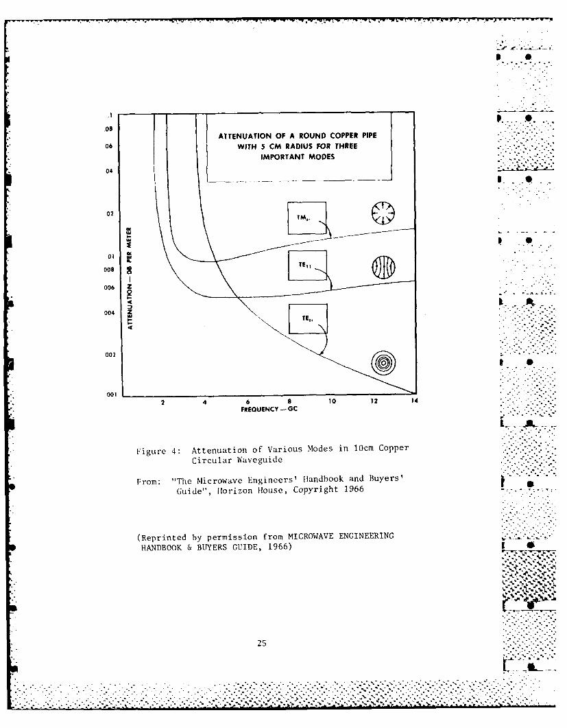
Figure 4: Attenuation of Various Modes in 10cm CopperCircular Waveguide
From: "The Microwave Engineers' Handbook and Buyers' .Guide", Horizon House, Copyright 1966
(Reprinted by permission from MICROWAVE ENGINEERINGHANDBOOK & BUYERS GUIDE, 1966)
A0'.
25
. . . . . . . . . . . .... ... . . . . .

1350 within 10 w sec.
Rotary Joints - Provided a circular polarizer is used at each end of a
circular waveguide, a rotary joint in circular waveguide is fairly easy to
implement.
Terminations - Terminations are made in the same way as for any other
waveguide termination. A tapered piece of lossy absorber material is
placed inside a section of waveguide. The taper of the absorber is
different for different modes. -
4.2.2 TE0 1 Mode, the "Low Loss" Mode ..
" 4.2.2.1 Mode TE01 Discussion
Of all waveguide modes, the circular TE01 mode has the potential to
have the lowest attenuation. Most waveguide modes decrease in attenuation i
as frequency increases up to a certain frequency. Beyond that point, most
waveguide modes increase attenuation as frequency increases. The circular
TE0 1 mode decreases in attenuation infinitely as frequency increases t
infinitely (Illustrated in Figure 4). It is because of this characteristic
that the circular TE0 1 mode has been nicknamed the "Low Loss" mode. In
actuality, this characteristic is not peculiar to only the circular TE0 1
mode, but is also possessed by all of its higher ordered relatives, the
circular TEon modes. Nonetheless, it is only the TEO, mode which has been
dubbed "Low Loss".
The "Low Loss" mode has two other unusual characteristics. First, it . . "
has no longitudinal wall currents. All electrical currents in the
waveguide wall travel circumferentially around the waveguide, none
26. . . . . . . . . . . .-. .. -........ . . .:-,... . . . . . .
. 26 ,.-. ...-. ,.
.- o"..-° . . .-r - °- *.- .

longitudinally along its length. Second, those wall currents which do
exist are extremely small. The TE01 mode has no electrical field lines -
which terminate at the waveguide's surface (See Figure 2), therefore, there
are theoretically no surface currents in the guide. TE01 waveguides may,
therefore, be made of aluminum rather than high conductivity copper with
little degradation in performance. Also, because there are no longitudinal
currents, electrical contact between the circular waveguide sections is not
* an absolute requirement. Flange losses are, therefore, lower and rotary
* joints are made much easier, almost trivial. It is also because of these
peculiar characteristics of the TE0 1 mode that mode filters and sharp bends
can be made simply.
The TE01 mode has an attenuation much lower than rectangular
waveguide. It is one third that of the TEll mode or about one tenth that
of standard rectangular waveguide for the same frequency range (See Figure
* 3).
This low attenuation is not gained without a complication, however.
* This waveguide is much more sensitive to the introduction of reactances
than is either the circular TEi1 or rectangular TE10 vaveguide. (Reactances
and their causes were discussed in the section on TEll waveguide.) This
sensitivity to reactances limits the minimum radius TE01 waveguide bend at
33 GHz to about an 18 inch radius of bend. If a bend is made tighter than
that, the VSWR will rise above 1.07 (see the section on bends to follow).,......
There are techniques for making TEO, bends with smaller radii than 18
inches, but these will also be discussed in the pages to follow, section on
TE0 1 bends. ~
The TE~l mode has lower loss per foot than the TEll but it's losses
27 s.'
, O ,
. .., . . .
. . . . . . . . . . . . . . . . . . . . . . . . . . . . . . .. .,.... . . . .

-quo,.
transitioning into or out of the mode are higher. Each TE01 transition -
loses only 0.2 to 0.3 dB, whereas each TEll transition loses only 0.1 dB
going to or from rectangular waveguide at 44 GHz. Because of these higher
transition losses, components such as terminations and directional couplers
find more use in TE0 1 (Low Loss) mode than in TEll mode. In the TEll mode,
it is nearly as effective to transition to rectangular waveguide and either
terminate the signal or measure the mode's power. *
The standard size for circular waveguide operating in the TE0 1 mode is
the largest diameter possible without allowing propagation of the TE0 2
mode. This size allows the propagation of 13 other modes (see Table 5). A
because of the many extraneous possible propagation modes, the TE01 mode
'aveguide is more sensitive than the TEll mode to waveguide irregularities
or bends. Luckily, all of these other modes propagate using longitudinal 3 "
surface currents and can be selectively attenuated without attenuating the
oil iode strongly. The TE0 2 mode does not contain longitudinal currents
,fnd conventional TE0 1 mode filters do not attenuate it. 1.
4.2.2.2 Mode TEO, Components
4.2.2.2.1 Co,!iponent Availability
TE0 1 components are not as readily available as are TEll mode
components. As communication frequencies have reached EHF frequencies only• %~~, ,' -. .-.
recently, and since waveguide losses were acceptable up until this time, %
the number of distributers is still limited. Several individuals or small %
organizations have developed their own designs for their own uses or for
profit. [he following list is by ro means all inclusive nor should it be ...-...-28
__A... ...-... . .. ..... ... . . . . . . . . . . . . . .. . . _ .__ ._ ... . .
• " •"_- .- ". ".- '-_-*L_ ._. . . . . .. . . . . . ."

* S
misconstrued as a recommendation of one manufacturer over another. This
list is mainly meant to show system designers, who are thinking of using %
mode TEoI, that some hardware does exist and is available which requires
little, if any, development. .' ,
Straight sections - Alpha, Azdar, and many tubing mills. Some tubing
mills such as Uniform Tubes Inc. & A.T. Wall have no minimum charge and
will handle small orders. Most tubing mills require a 1000 lb minimum
order.
Precision Straight sections - Azdar and many tubing mills.
Bends - There are two methods of making bends: *!
(a) Conventionally bending the waveguide.
(b) Making a waveguide section which is internally corrugated.
Conventional waveguide bends - No waveguide manufacturer or waveguide "
bender at present will guarantee the results of any TE0 1 waveguide sections
which they bend to shape. (Some will bend with no guarantees.) However,
bends may be made in-house by filling the waveguide before bending and by
keeping the radius of bend greater than 18 inches.
Internally Corrugated Waveguide Bends - These must be electroformed to
maintain the tight tolerances required. Many electroformers will produce
these bends including A.J. Tuck, Gamma F of CA, and Servometer.
Transitions/Transducers (TEol to rectangular TE10 )
(a) Iris transitions - Alpha TRG ,
(b) Marie' transitions Mr. Tor Anderson of Antennas tor Communication
°- , . ,• o
Corp., who works closely with A.J. Tuck, Inc. of Connecticut has a design.
Harris Corp also has a design. Both have been manutactured, tested and
work well. Most electroformers such as A.J. Tuck or Gamma F. can
29
.. , ,..

71~ II '
electroform the transitions. Marconi stocks marie' transitions up to 40
GHz.
Transitions (Circular to Circular) - Alpha
TE0 1 Rotary Joints - Alpha, most rotary joint manufacturers, Harris
may have a marketable version of their design.
Terminations - Alpha.
Directional couplers - NOSC has a design coupling circular Q-band '- ..
circular waveguide into WR22 rectangular waveguide.
4.2.2.2.2 Component Descriptions ft.
Straight Waveguide Sections - Straight waveguide sections and
precision straight waveguide sections are identical to those used for
circular mode TE11 . Because of the low wall currents of the low loss mode, | g
aluminum or another metal with a lower conductivity than copper or silver
is satisfactory for use. Copper and silver waveguide is more readily
available, however, being used already for the TE11 mode.
Bends-low lossses in TE0 1 circular waveguides depend on the waveguide "
being circular. If the waveguide becomes elliptical, other modes are
generated and attenuation increases. Bending a circular pi.pe produces an ts
elliptical cross section by nature. In order to keep the cross section a
circle, extreme care must be taken in bending. Large radius bends with a
small (900 or less) angle of bend can be made by conventional bending "-
techniques (filling the guide with sand or Serrobend, bending, and then
removing the filling). To make tight radius bends, a technique of
electroforming internally corrugated, bendable waveguide sections has been
developed. These techniques will be discussed separately.
30
. . . . " ,- . , ,. - .° . - , - . .•. , . . , . . - . . ." . % " , . " - . ' " ,- . - ,
... .. " 'F . " . ,. -, . -. --L '-.'.. " .'- " i .. - , . '- .. ... '

The Navy SPN42 automatic carrier landing system experienced some "
difficulties with making waveguide bends. It used some circular low loss
mode at 33.2 GHz in waveguide with an internal diameter of 0.688 in. Some
installations required bends in the guide, but no manufacturer would
guarantee a successful product. The unguaranteed bends which were produced
were unsuccessful and had unacceptable VSWR's of 1.6 to 1.8. So the Navy
had their personnel at the Norfolk Naval Shipyard combat systems office try .
to make some bends in-house. Results were much better. BY filling the
waveguide with sand or a wax-like material prior to bending the guide, . .
acceptable VSWR's of 1.07 or less could be achieved on 18" radius 450 .. . ."" . .
bends. Besides the one 450 bend, six 30 bends were successfully made with
18" radii using this technique. However, successful small (under 18")
radius bends cannot be made by this technique.
I N..... ,,......
Figure 5: Internally corrugated electroformed bend for "Low Loss" mode
The best method for making small radius bends in circular waveguide is to I.I
use electroformed internally corrugated waveguide sections. The TE01 mode
has no longitudinal wall currents, only circumferential ones. By cutting
circumferential grooves into the inside waveguide surface, the waveguide is Ldivided into a series of connected rings. Surface currents may flow
31 - '
OLI *t.... + + +. .. . . . . . .. .+ .. ??:+ :>
. . i ."...:. - •. -- . "., .. .. .. . • . ..% .". .. .. . . . . " "" '" - "" "-' "- . -

circumferentially not longitudinally, thus suppressing the generation of
any extraneous modes. In addition, these circular corrugations perform in
a truss-like manner to preserve the circular cross section of the waveguide
when the waveguide is bent. For best effect, the corrugations should be
made one quarter wavelength deep so as to appear like an infinite impedance
to longitudinally propagating surface currents (a quarter wavelength stub
ending in a short). There should be at least four corrugations per _.
waveguide wavelength or else their effect diminishes according to NOSC
unpublished test results.
The best technique for producing these corrugated bends is to
electroform straight sections on a mandrel, dissolve the mandrel, and then
bend the straight sections to the desired curve. A new mandrel must be
machined for each bend. Depending on the materials used to electroplate
the mandrel and their thickness, the corrugated bend may be either rigid,
semi-rigid, or flexible. Semi-rigid bends may be formed by electroforming
copper on an aluminum mandrel, dissolving the mandrel, and nickel plating
the copper guide. By using non-work hardening metals like nickel, flexible
bends can be made. The interior surface of a bend may be electroplated
with silver or copper for better conductivity. NOSC measurements on actual
bends show a 0.2 to 0.25 dB loss through an 8 inch section at 45.5 GHz with.P.
a bandwidth of 2 GHz. Bandwidths of corrugated waveguide bends are limited
to about 2 GHz at 45 GHz. This limitation is caused by the limitedS
effective frequency range of the quarter wavelength corrugations.
Threading the interior of circular waveguide rather than electroforming has
been tried by NRL but results were unpredictable and low yields were
experi enced.
32
.,. -

Stanidarix Rec "t l Ia S iid
Standard Rectangoilar to ')tcmtidrd Pectanoular toOversi:Oed RcctanI igiiar C cu la r LIIM
SIAN [).RI) RI WIA.GU IAR '1 TO Uss LOS CIRC I II i At.2
MIarie,
1 ri1 Sectoral
-e 0: W Ieti Ic Trans it ions

- .-. . . . . . . . . . . . . . . . . .- - .... -
Mode Filters The simplicity of TE 0 1 mode filters is one of the chief
reasons why the low loss mode is so easy to work with. The same techniques
used to make corrugated bends can be used to make effective mode filters.
Circumferentially grooved circular waveguide attenuates all modes except... ,. .. - "
the TEon modes. In a mode filter, the grooves between the ridges internal
to the waveguide are filled with a lossy energy absorber. The absorber
accentuates the mode filtering effect of the grooves. Like internally
corrugated waveguide bends, this mode filter design must be electroformed.
An alternate, but similar, approach to mode filter design employs a
wound helical wire form surrounded by energy absorber material. Like
internal corrugations, the spaces between the coils of the helix prevent
longitudinal current flow allowing only circumferential currents.
Cormmercially available, this design works nearly as well as the *
electroformed type and is cheaper to manufacture. Manufacturer's
' literature for this design quotes a maximum insertion loss of 0.2 dB for
TE 0 1 propagation from 33 to 50 GHz.
Transitions/Transducers - There are three types of low loss mode
transitions: the sectoral, which is no longer commercially available; the
iris, which is commercially available; and the marie', which is
commercially available but has only been designed, manufactured, and tested
in limited quantities for higher frequencies. (See Figure 6)
The sectoral transition geometrically transitions from a rectangular
to a circular waveguide. First, one narrow wall of the rectangular
waveguide is reduced in width until the waveguide's cross section becomes
triangular. (See Figure 6) Next, the triangular guide gradually widens
its arc until it forms a circular waveguide with a narrow wall in it.
34
.. "-.'- .. .. ,. .'.
.. . . . . . .. . . . . . . .. . . . . . . .. . . . . . . . .. . . .. . . .
, ~... . ... - ... ".. "-. .. '.. .... -' ' " ..'..'".". . -. ,. .. .... ". 'i" ".... . . .. ".' "".""

Lastly, this wall is decreased in size to leave a circular waveguide. The
TE0 1 mode emerges along the same axis as the original TElO mode which
entered the transition. Being a geometric transition, the sectoral can
have a broad bandwidth. Sectoral transitions were manufactured by Hitachi,
* 0 4but their circular waveguide line was discontinued when sold to Hughes.
There is no advantage to redeveloping this transition since the marie' has
the same characteristics.
The iris transition is a narrow band device with its bandwidth limited
to about 6%. In this transition, the narrow wall of a standard rectangular
waveguide is separated by a thin septum, forming two parallel, thin
waveguide sections. An iris is cut in one of the narrow walls and a . -
circularly oriented E-field is used to transition between modes TE10 and
TE0 1 . Thus the output of an iris transition emerges at right angles to the -
input. The iris transition is a very reactive device: say for example, if -
two transitions are separated by a short length of circular waveguide, mode .'- -
filters may be required. The same may be true if a transition is followed
too closely by a waveguide bend or other reactive device. Unless reactive
effects become involved, iris transitions will perform almost as well as
marie' transitions with iris losses being 0.25 to 0.3 dB per transition. -.. .
Marie' transitions, like sectoral transitions, use a geometric design
and are broad band devices. The transition to the low loss mode is "
performed in three stages. (See Figure 6) First, the TE 10 rectangular ...-.
mode is transitioned to TE20 rectangular mode. By attaching the narrow
wall of the TEl0 rectangular waveguide at right angles to the broad wall of . . .
a piece of waveguide which is twice as long, the TE 2 0 rectangular mode is .N *** k
generated in the wider waveguide. This overly wide waveguide is then split
35
............... ................" .. "". .............- ". . . . .. . . . "" a¢i ' ..: ' -'.2 : . '._2 ..- _' "• .¢ .' .' . . ' € '; _:. ..' .' €'' .:' f _' Z _''mf'. "._-. .*-.*"-. .' '~
x - -

at each end to form a "dog-bone" shaped cross section for the guide. This
splitting at each end continues until an X-shaped cross section is formed.
This X-shape is then gradually thickened to leave only the circular
waveguide remaining. If properly designed and manufactured, the impedance -
of a marie' transition is purely resistive, therefore, mode filters do not
become necessary unless other reactive devices are involved. Insertion
losses are 0.2 to 0.25 dB per transition and as with the sectoral type, the I S
output energy is collinear with the input energy. Harris has recently
manufactured Marie' transitions with only 0.1 dB loss.
Rotary Joints - Single channel rotary joints are simple with the TEO1
mode. Because of the lack of longitudinal currents, electrical contact
between the two sliding waveguide interfaces is not essential. High power
transmission with losses can be easily achieved. If a second channel is 3 S
desired, however, another mode must be used because orthomode transducers
do not exist for the TE01 mode, which do not affect any energy already
present in a circular waveguide.
Terminations - Terminations are commercially available and are easily
formed. A conical piece of absorber material placed in the end of a
truncated section of circular waveguide does the trick nicely (with VSWR's "
of 1.05 or less).
Directional Couplers - Since WR22 is the standard interface for
instrumentation at 44 GHz, a directional coupler which samples a small
* portion of the signal in a circular waveguide and has an output in
rectangular waveguide is useful for monitoring active systems. Although "'"
there are no commercially available units that I have found which sample "'-
TE0 1 mode, NOSC has an excellent design for a 20 dB directional coupler.
36
. ',,-

lopo. XT. V..".
This design has a coupling of approximately 20 dB into WR22 waveguide with ,
an isolation of 34 dB. It can simultaneously couple forward and reflected
(reverse) power so that readings of transmit power and calculations of VSWR
can be made in operating circuits.
4.2.2.2.3 Operational Experience
Bell Laboratories researched a great deal of what we know today about
mode TE01 during the 1950's and 1960's. Their research was directed . -
towards developing a low attenuation method of transferring extremely wide
bandwidths for several miles. This was related to the picture phone • .
concept which required extremely wide bandwidths to be feasible. When ! -
research in fiber optics began, Bell's research of oversized low loss mode
waveguide stopped. Much of their work has been published in the Bell
Systems Technical Journal. (See Appendix 2) The Japanese used oversized, •
over moded TE01 mode waveguide underground. Nippon Electric used oversized .-.'-
circular guide to transmit telecommunications for several miles underneath
city streets. Most of their circular waveguide equipment such as mode . .
filters were made by Hitachi. Nippon Electric replaced their circular
waveguides with fiber optics. Hitachi sold their waveguide manufacturing
to Hughes who discontinued production of the circular components due to low
demand.
The best example of operational experience with standard sized low
loss mode circular waveguide is the Navy SPN42 System. The SPN42 is an
automatic carrier landing system which operates at 33.2 GHz. On some .....--,'-. .. .. '. .. ,
aircraft carriers (such as the Midway) waveguide runs from the transmitter
to the antenna can be as long as 20 ft. These long runs are necessitated
37 .- .
.. °-'.--..-.......-..
- - . - .-.-.- . . . . . . . . . . . .-... .
37.. . . . . . . . . . . . . . . . ..-...

W -J " 1S - "
by the transmitter's need to be sheltered from the weather while the • -
antenna must be located high on the tower and exposed. Although originally
implemented 19 years ago using rectangular waveguide, some of the carriers
were modified to use circular TEo1 mode waveguide around 1977-78. Only *
those carriers with waveguide runs exceeding 15 feet from transmitter
output to antenna pedestal were modified to use circular TEO.
Coin silver rectangular RG96 waveguide (WR28) was replaced by
WRCI16C14 (0.688 in internal diameter) circular waveguide on runs generally
15-18 feet in length. Iris transitions were used along with mode filters
after each transition. Total loss for the circular waveguide run was -
specified to be less than 2.0 dB from transmitter output to antenna
pedestal. These specifications were achieved and there was no increase in
;Raintenance caused by the use of circular waveguide instead of rectangular.
This is according to the Naval Electronics Systems Engineering Activi.ty
(NESEA) which monitors, tests, and certifies modifications or repairs to
the SPN 42 System. p
This is not meant to imply that the SPN 42 circular waveguide was used
without problems. Besides the difficulty of bending low loss mode
waveguide (which was discussed in the section on TE01 mode bends), the main 9 -
problem which the SPN 42 System waveguide suffered from was the growth of
green fungus within the guide. This occurred with either rectangular or
circular waveguide and was related to the environmental exposure of the
6;uide and not to the type of guide used.
Lead times on the SPN 42 circular waveguide components were considered
to be long by the Norfolk repair personnel. The Oxygen Free High
Conductivity (OFHC) copper circular waveguide had a lead time of 8-10
38
,..........'..".o" .
. . . . . . . . .. . . . . . . . . . . . . . . . . . . . . . . i~

* S.
months. Silver waveguide averaged about a month longer. To retard
corrosion of the copper guide conformal coatings were applied. The
. coatings used were either Alodine or Iridite depending on whether a
conductive or insulative coating was required. These coatings were applied _
at Norfolk so their lead time was negligible. Lead times for the iris
transitions and the mode filters could be up to a maximum of 150 days. -
The new version of the SPN 42 system no longer requires the use of
long runs of waveguide. The SPN 46 system collocates the transmitter and
the antenna pedestal. The need to use circular waveguide no longer exists
with this new system. •
4.3 OVERSIZED WAVEGUIDES
Generally, the attenuation of a waveguide decreases somewhat linearly - .
as the surface area or circumference increases. The obvious question is,
therefore, "Why not use a very large waveguide and achieve a very low
attenuation?". This is precisely the principle behind oversized or -.-- .
] overmoded waveguides.
There are limits on how large a waveguide can be oversized before its
attenuation begins to increase rather than decrease. In addition, -. *
oversized waveguides cannot be bent. In spite of these restrictions,
oversized waveguide offers the lowest attenuation for long waveguide runs
* and its use should be examined.
o As a waveguide's size increases, the number of modes which can
propagate through it increases dramatically. An oversized waveguide is a
waveguide which allows many modes other than the desired mode to propagate,
39 e
.. ',,.. -,. ,,
~~....... ....... •............-,-"... "- .... ''... .Z," °' .--..- ,"-. " , -'"-- - . .. - .. . _.., ,- -- K_-,, - .. . .. . -- ., .L • -_ -',i _" _.,_ ' . * , .- . . # '0 I

some of which cannot be filtered separately from the desired mode. For *rectangular TEl 0 mode waveguide, oversized means any size larger than the. .
minimum to propagate the TE20 mode. For the circular TE0 1 Low Loss mode
waveguide, it is any size larger than the minimum to propagate the circular g
TE0 2 mode. For circular TEll mode, it is any size large enough to
propagate the low loss mode.
The large number of modes which can propagate through the waveguide
makes oversized waveguide extremely sensitive to surface irregularities or
bends. As is the case with standard sized circular waveguide, bends or
irregularities tend to couple energy from the desired mode into undesired i *modes which must then be filtered out. Since filtering cannot eliminate
all unwanted modes, and since the impedance of the waveguide to the many
unwanted modes is extremely low, an unacceptably high percentage of power
is lost by bending oversized waveguide. Therefore, oversized waveguide
cannot be bent. Surface irregularities or imperfections lose power also.
Using precision waveguide reduces these losses to acceptable levels. I " .
Oversized waveguide, just like standard sized waveguide, can be made
with any cross sectional shape. Generally, only oversized rectangular or
oversized circular waveguide is used. Only precision waveguide should be
used. Precision circular and rectangular waveguides are available from -
precision waveguide manufacturers such as AZDAR (a division of EVERED, a .. .
British Company). p i
-
40 ~
....--. ..- '.-.
.. . '. , . °
. . , . . .A,.. ..-.. * . '°
4.3.1 Oversized Rectangular "
Of all oversized waveguide types, oversized rectangular waveguide is
the least troublesome to use. Its ease of use derives from both its higher..... - 4
attenuation per foot and from the simple design of its mode filters.
Losses in transitioning to and from standard rectangular waveguide are low,
nearly as low as for standard sized circular TE0 1 Low Loss mode. By * _
expanding standard rectangular waveguide correctly into oversized waveguide
sizes, standard sizes (1:2 dimensional ratio) of waveguides may be used for
the oversized waveguide also (WR 62 or 75). p
For waveguides in general, the lower the waveguide's attenuation, the
higher its sensitivity to irregularities. In comparison with oversized
Circular waveguide, oversized rectangular waveguide is more tolerant of .
irregularities, bends, or guide distortions. Mode filters are not required
as often on an oversized rectangular waveguide run as on an oversized
circular waveguide run. .
Although not as sensitive to guide imperfections as oversized circular
guide, oversized rectangular waveguide must use precision waveguide with
tight dimensional tolerances. In Naval Electronics Laboratory Center Tech
Note #2088, dtd 27 July 1972, two WR 112 waveguide sections were compared
while being operated as oversized rectangular waveguide in the TE0 1
rectangular mode. One was precision WR 112 with dimensions +/-.001 while -
the other was standard WR 112 with a dimensional tolerance of +/-.003
inches. A theoretical value for the attenuation of WR 112 operating in the
TE 0 , mode at 38 GHz was calculated. The precision and standard guide " "" ..*i**
41 .. . . .
.- ~~~~~~- .:- --- . - -y

losses were 21% and 54% larger, respectively, than the calculated p •
theoretical value of .028 dB/ft. Although the calculated value assumed a
d.c. value for the conductivity of copper and although only a single sample
of each waveguide was tested, it appears that precision waveguide must be .
used for oversized rectangular waveguide runs.
Besides its low attenuation per foot, another characteristic which
makes the use of oversized rectangular waveguide appealing is the low * S
transition loss. Oversized rectangular waveguide losses are usually not as
low as the low attenuation per foot achievable in standard sized circular
TE0 1 mode waveguide, but the transition losses are much less. Oversized
rectangular transitions lose only 0.1 dB transitioning to or from standard -.-
rectangular waveguide while circular TE0 1 mode transitions lose 0.2 to 0.35
dB. . .
A tradeoff decision must be made when choosing how large to make an
oversized rectangular waveguide. Larger waveguides cannot be manufactured
to the same tight tolerances as smaller waveguides can. By using a larger
waveguide to decrease the attenuation, eventually attenuation is increased -
more by the lower waveguide tolerances and increased sensitivity to .
imperfections than it is reduced by the increase in waveguide size. This I *
optimizing tradeoff should be performed each time an oversized rectangular
waveguide transmission line is being planned.
The best way to expand from standard sized rectangular to oversized
rectangular waveguide is not to simply expand both waveguide dimensions .... . .
. 7.. . . .
I S..
.' ~~~~~~~42 ,,''' ,.. , ""
9. .9•• •,.
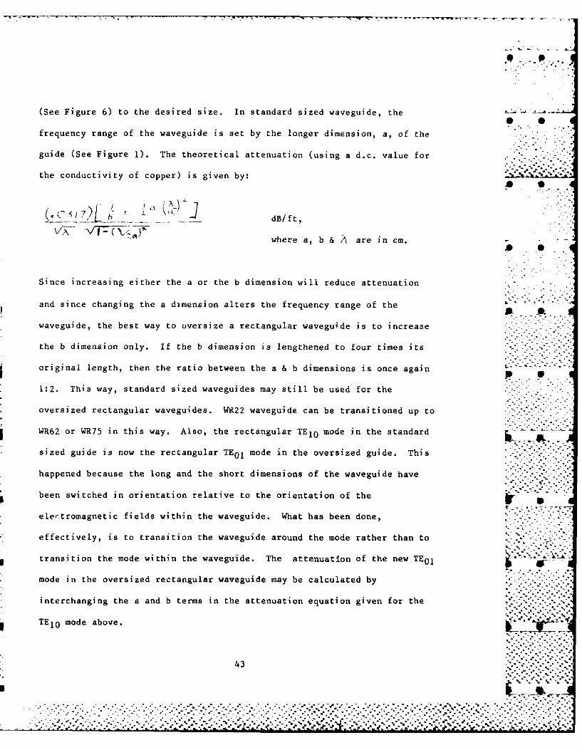
(See Figure 6) to the desired size. In standard sized waveguide, the
frequency range of the waveguide is set by the longer dimension, a, of the
guide (See Figure 1). The theoretical attenuation (using a d.c. value for "' . "*'
the conductivity of copper) is given by:
_ . ... .. .. .. ._dB / ft ,
where a, b & A are in cm.* S
Since increasing either the a or the b dimension will reduce attenuation
and since changing the a dimension alters the frequency range of the
waveguide, the best way to oversize a rectangular waveguide is to increase
the b dimension only. If the b dimension is lengthened to four times its
original length, then the ratio between the a & b dimensions is once again
1:2. This way, standard sized waveguides may still be used for the
oversized rectangular waveguides. WR22 waveguide can be transitioned up to
WR62 or WR75 in this way. Also, the rectangular TEl 0 mode in the standard
sized guide is now the rectangular TE0 1 mode in the oversized guide. This
happened because the long and the short dimensions of the waveguide have
been switched in orientation relative to the orientation of the
electromagnetic fields within the waveguide. What has been done,
effectively, is to transition the waveguide around the mode rather than to
transition the mode within the waveguide. The attenuation of the new TEO1
mode in the oversized rectangular waveguide may be calculated by
interchanging the a and b terms in the attenuation equation given for the
TE1o mode above.
43,- . 0
. . . . . . . . . . . .. . ...-.--.. . . . ... ,,,
~~~~~. . ..... ..-........ . . . ,. . .. ,.,..............-. °.....-° .,•
_ .- '.,P ,t_ _ '."_• - _. - ! .j t. .- =.'- L- " .L'= =. ,' T.. ". - ." 'h " ' '-1 R.d_ _P ' . ._.m.-
._'

The simplicity of design of effective mode filters is one of the chief 0
advantages of working with oversized rectangular waveguide rather than
other oversized guides as can be seen from Figure 2, the electric lines of
force of the TE10 mode terminate on the broad wall of the waveguide. Since * .
these electric lines are symmetrically distributed about a line centered
midway down the length of the broad wall, there is no voltage differential
and, therefore, are no surface currents which exist across that line. By S
making a slot along this line down the center of the broad wall of a TE10
waveguide, the waveguide section acts as a TE10 mode filter, attenuating
most other modes but not the TE10 mode. Similarly, making a slot down the . .
center of the narrow wall of an oversized rectangular waveguide acts as a
mode TEoI filter. This is a very simple design for a mode filter and can
be manufactured easily by any in-house machine shop.
4.3.2 Oversized Circular
Use of the low loss mode in oversized circular waveguide is the lowest rloss method of transferring millimeter wave power. It has been studied
extensively by Bell Telephone of the U.S., CNET in France, and many others
during the 1950's and 60's. Although they extensively studied the low loss
mode TE0 1 , transmission of mode TEll or any other circular mode is also
possible through oversize circular waveguide. The real need to use any of -
these transmission methods arises only when transferring EHF power for
distances of 100 ft.or more. Because of extremely low attenuations, these
methods are even more sensitive to irregularities or bends than the
44 -
............................................

S O
oversized rectangular guide is. Mode filters are required at regularI 0
intervals in an oversized circular line to dampen out unwanted modes. .....-
Losses of 3 dB per mile are possible at millimeter wavelengths using 2 inch
TE0 1 mode waveguide. For mile length runs, oversized TE01 mode waveguide
is the only choice, but the restrictions on its use make other alternatives .
a much better choice for shorter runs (under 50 ft.).
t..
45
I": - . -

4.4 DIELECTRIC WAVEGUIDE
E2
3 0
LOSSY OUTER LAYER 3 -
Figure 7: Rectangular Dielectric Waveguide
Dielectric waveguide is unlike other waveguides. It is not a hollow
metal structure. In fact, it doesn't have conductive metal layers at all.
Behaving much more like fiber optics than conventional waveguide, it
bridges the gap between these two technologies. Dielectric waveguide, as 0 •
shown in Figure 7, consists of a central core of relatively high dielectric
constant (El ) material surrounded by a layer of lower dielectric constant
CE2) material. The majority of electromagnetic energy propagating through p
the waveguide is maintained within the inner, high dielectric region. This
propagation is often looked at in one of two ways: 1) As a TEM mode
propaga'ng through a region with two different dielectric constants, 2) as -
a low frequency fiber optic transmission line. (The electromagnetic energy
is internally reflected within a central region having a high index of
refraction surrounded by a region with a low index of refraction.) Because
the index of refraction is equal to the square root of the dielectric
constant, these two points of view are equivalent. Just as with fiber
optics, the worst performance of dielectric vaveguide is through minimum
46
. 4 . °
. . . . . . . . . . . . . ." - - " - - ' ." . - " -'.' - - '- . - "- " ' - -"- ,--- . . . . . .."."- -"- :'--" -:'-. i" '

radius bends. Bends increase the attenuation of a dielectric waveguide and* 0
decrease its power handling capability. Just as with fiber optics,
increasing the dielectric constant (or index of refraction) of the central ""
core relative to the surrounding medium increases the performance through
bends. More energy is retained within the core and less energy will be
lost passing through bends. However, increasing the dielectric constant of
the core, using present technology, increases the loss tangent of the
central core, and increases attenuation. This technique of increasing the
core dielectric constant is used to decrease the minimum radius of bend
where it's required. The choice of ratio of the dielectric constants
between the inner core and its surrounding material is one of the trade-off
decisions which must be performed when optimally designing a dielectric
waveguide. -
The theory of dielectric waveguides is not new, but the recent
development of a dielectric material with a low loss tangent has made low
loss dielectric waveguides possible. The loss tangent is related to the
amount of energy lost per foot propagating through a dielectric.
Polytetrafluoroethylene (PTFE or the same materials as "Teflon") has a low
loss tangent. By foaming it out to form expanded PTFE, its loss tangent "
can be decreased still further. Losses can be reduced to the point where a
I 1 inch rectangular cross section dielectric waveguide of expanded PTFE can
have losses at 44 GHz of 0.12 dB per foot. This is half the loss of W AIr
rectangular waveguide (WR 22). In addition, these losses are not greatly
affected by frequency. At 100 GHz, the dielectric waveguide losses can be
as low as 0.3 dB per foot.
The main advantage of expanded PTFE dielectric waveguide is that it is
47
--- :2:-~i" " ".. . ... ......................... . ....
.':.:. £.2, :.:.............. ............ . ....... .: .......-... ,.,..,.:,~~~~~..... ....-......... ,......... -"• .•-".-.-. •.- .-.. '-"..;,,",.',":,',",:

continuously flexible over its entire length. PTFE has been used as
insulation in coaxial cables for SHF and EHF transmission for years. It is
resistant to vibration and flexible. Flexibility is a relative term
however, and the flexibility of a 1 inch diameter dielectric waveguide
would be comparable to the flexibility of a 1 inch coaxial cable, which is
fairly stiff, especially when jacketed. Among the disadvantages of
dielectric waveguide is the relative lack of test data to verify waveguide *
performance. Expanded PTFE dielectric waveguide is a new development and
relatively few samples of completed waveguide sections are available for
testing purposes. Kollmorgen Corp. has one or two samples for evaluation. AL
NUSC's Electromagnetic Systems Dept. has four samples for testing. The
only other test data available is supplied by W.L. Gore & Associates, the
sole manufacturers of this proprietary product. Test results from the p.
manufacturer are available for each sample, test results from Kollmorgen
are available, and test results from NUSC will be available soon. The most
extensive test data base currently available is from the manufacturer, W.L.
Gore & Associates.
Gore has produced both circular TEO, mode and rectangular HEll mode .- -
dielectric waveguides. Of these two, the rectangular dielectric waveguide
appears to be the better performer. Judging from a limited number of
samples, the losses in transitioning into or out of the dielectric
waveguide appear to be inordinately large. The design used for the
transitions is a simple conical type which has the relatively high loss of
0.7 dB per pair. This indicates a need for development work in the area of
dielectric waveguide to standard rectangular waveguide transitions.
The optimum diameter of a dielectric waveguide varies with the
48
~~~................... .......... ....................... ............. .. .,-....i..; _... -- -- -- - : - ... .. - - -. -.. . . . .. . . . . . . . . . .... ..---.--. .-.--..----.....-.-.--..-..--.-. ..-.... .-. .,. -.-.-. - . .,' -. . , , .-.. - .....-., .- -......-..... .-..-...... .......-....... '........-.:..".. .. ., .-. ' ."

7--777 P 7-' -. , 7-.. .
waveguide's operating frequency range. 40 GHz waveguides have diameters .* . 4
between 2.0 in and 0.75 in. 95 GHz dielectric waveguides have diameters of
between 1 in. and 0.25 in. Since the minimum bend radius is 6 times the
waveguide diameter, higher frequency dielectric waveguides are much more
flexible than lower frequency dielectric waveguides. 1.
For higher frequencies, dielectric waveguide appears to be an even
more attractive option. Not only does the waveguide become more flexible, .
but its attenuation as compared to standard rectangular waveguide becomes
even better. At 44.5 GHz, the attenuation of 1.5 inch rectangular
dielectric waveguide appears to be somewhere between 0.1 and 0.15 dB per
foot. This is an improvement over WR 22 by about a factor of 2. At 96
GHz, the attenuation of dielectric waveguide appears to be around 0.3 dB
per foot. The attenuation of comparable rectangular waveguide is between 1
and 1.5 dB per foot yielding a factor of improvement of between 3 and 5
over standard rectangular waveguide attenuation. These advantages of
increased flexibility and lower relative attenuation can cause dielectric '
waveguide to be the right choice for use at a higher frequency in the same
application where it may not be the best choice for use at lower - -
frequencies. "
The measured performance of dielectric waveguide around 44 GHz is
good. Two 1.5 in. diameter rectangular dielectric waveguide sections with
lengths of 3 and 9 feet have total attenuations of 1 and 1.5 dB -
respectively from 43.5 to 45.5 GHz (See Appendix 3). These measurements
imply a 0.75 dB attenuation per pair of transitions and under 0.1 dB
attenuation per foot of straight dielectric waveguide. A minimum radius '
bend with a 9 inch radius increases attenuation less than 0.25 dB per 90°
49- . .-
' .. . .. %
• , . .. .. -°. -. - • . . °. . .. . . • . . . .. . .- .. - , -. - .. .. ° -o o. . .. o . . . '- .. • ° . - • . . • " . . . . • . .-' i Z - ~ -: - ,_i -... : _ ,,7 .-, ..X.-....-.- '-- ., . -. --'_-'i".-.. .- ,_".. -.:.'-,'.-.. :7 '..7 ,: .'..;.:,...... .. ': -"": - "" •."A

0
of bend. A bend with a larger than minimum radius increases attenuation
0.25 dB per 3600 bend. The maximum power handling capacity of the
waveguide exceeds 100 W through a minimum radius bend. Bending the
waveguide more sharply than the minimum radius bend causes excessive power ---'S|4
loss and a resultant heating up of the outside lossy layer of the guide.
The waveguides are generally designed t% pass a 10% bandwidth. Some
dielectric waveguide test data is included in Appendix 3.
Dielectric waveguide is not perfect however, and still requires some
development, especially in the area of shielding. Coverings are required
- on the waveguide both to prevent electromagnetic interference (EMI) and to
protect the dielectric material from physical damage. In an operational
environment, where other electronic equipment is present around the
dielectric waveguide, shielding becomes necessary to prevent the - •
waveguide's signals from interfering with the surrounding equipments'
signals and vice versa. In addition, the presence of a conductor near an
unshielded dielectric waveguide alters the electromagnetic fields within
- the guide and can increase attenuation. Early samples of dielectric
waveguide were unshielded, which caused problems whenever the waveguide was "
tested in the proximity of a conductor. Now, all dielectri.c waveguides are
shielded, and EMI shielding is no longer a problem.
Physical damage i.s a danger to expanded PTFE dielectric waveguide just
- as it is to metallic waveguides. The expanded PTFE material is not very
. resilient. Crimping or dinging a dielectric waveguide may permanently
degrade its performance. Due to the relative softness of dielectric
waveguide in comparison with a metal waveguide, dielectric guide must be
protected if the possibility of extremely rough handling exists. Because
50
,--,~~~~~~~....-..,-...........-..-.......,....,..,. . .................... ....... ... . ,. ., '..... . .. ..

of the newness of the dielectric waveguide, an effective sheathing
technique has not yet been tried in an operational scenario but there are
several alternatives. Gore intends on using either the stainless steel
armor or the hardened steel spring sheathing which has proven extremely " '
successful with their line of microwave cables. Either of these techniques
will probably work well. For normal usage, an aluminized Kapton EMI shield
with a plastic sheathing is all that's required. " .
In summary, ajelectric waveguide is a unique type of waveguide with
unique properties. In any application over 7 feet in length, dielectric
waveguide sections will have lower losses than standard WR22 rectangular
waveguide. If a waveguide, which is flexible over its entire length is
required, dielectric waveguide is the answer, provided a 1.5 inch diameter
and 10 inch bend radius can be tolerated. Some effort is underway in - •
dielectric waveguide developing dielectric waveguide transitions with lower
attenuation and in shielding the waveguide from physical damage. At higher
frequencies in the EHF range, its somewhat bulky diameter and intolerance
for tight bends diminish so that dielectric waveguide is an even more
* attractive option at these frequencies. Even at 44 GHz, it i~s an option..
which should be considered. _--s
51
. .. . . . . . . . .,.-:
, - -- - - - - - - - - _. . " ' ,- r
. . . . . . . . . . . . . . . . . . .. . . . . . . . . . . . . . . . . . . . . . .
. ~ . . .. ... . . . . .Il ili ieI .. . .. . . . . . . . . . . . . .

, , . -.
SECTION 5
THE DECISION PROCESS
5.1 DESIGN CONSTRAINTS
In each application where waveguide losses are to be minimized, there
are requirements placed upon the waveguide caused by physical restrictions
on the waveguide's path. Each of the technologies just presented has its
capabilities and limitations in meeting these physical restrictions while 0
still maintaining low losses. By first determining the physical
requirements caused by the installation and then choosing the lowest
*. A* attenuation method which fits those constraints, the lowest attenuation
technology can be chosen.
5.1.1 Installation Derived | U
The.installation in which the low attenuation waveguide will be used
determines both the overall length of the waveguide run and the bendability
"- which will be required of the waveguide. The overall run length can be
measured for each installation. This is a straight-forward end-to-end
measurement of the waveguide run from start to finish. The bendability
constraint needs to be explained more fully.
Bendability can be categorized as either non-bendable, rigidly
bendable, semirigidly bendable, or flexible. Each installation sets the " "!
minimum bendability requirements for the waveguide being used in that
installation. Not all installations can use a straight run of waveguide.
Take, for example, an aircraft where the transmitter is located in the
,. ... . . . . . . ..2
52 '" ".. . *".." * . . . . ."

* S.
electronics bay in the belly of an aircraft and one or more antennae are
located on top ot the fuselage. It may not be permissible for a waveguide i'
to cross straight through a crew compartment in-between. In this case at '-
least rigid bends would be required. Semirigid bends often become
necessary as a result of the real world of manufacturing tolerances. Not
all aircraft are exactly identical in size. If a transmitter/antenna
system is to be mass produced and installed on all aircraft of a particular
type, when it comes time to install the waveguide sections on the aircraft
not all of them will tit exactly. To compensate for these minute
differences between iastallations, semirigid sections or "snake lines" can I
be used rather than individually customizing each installation. These
sections are invaluable as timesavers during maintenance or installation.
Semirigid sctions have their limits as to the number of times which they -
may be bent before metal fatiguing or failure occurs. If the installation
calls for repeated flexing, flexible sections are required. Examples of
this need would be sections located at a wing root going into a wing or
sections periodically spaced down a long run in a fuselage to localize
bending stresses caused by aircraft flexing. Such localizing relieves
bending stresses from the majority of the waveguide run length.
.. .- .- . - .. ..
* . " . . ,. - ° - "
53
....... ..-........................................ %

Table 7 -Technologies and Bendabilities Arranged by Attenuations at 44 GHz
*Technology Attenuation(dB/ft) Bendability
oversized circular TE01
2" Diameter .00055 Non-Bendable
1" Diameter .004 Non-Bendable
* TEll
2" Diameter .0055 Non-Bendable
Standard Sized Circular
*TE 01 .036 Rigid(18"Radius)
* Oversized Rectangular
*TEII .097 Rigid
WR62 .042 Non-Bendable
Rectangular 1.5" .12 Flexible (Dielectric) :'
Square .224" .15 Rigi.d
*Rectangular WR22 .229 Rigid
Rectangular Flexible .6 Flexible/Semirigid
Circular TE0 1 Internally .~ -
Corrugated Bends .4 Flexible/Semirigid
54.........................................................

- -".. *o-' .,. * . . . .-. "- o
5.1.2 Technology Inherent
Each waveguide technology has its own limits of bendability. Ate
bendability of waveguide technologies which can achieve attenuations less - --
than standard rectangular waveguide at 45 GHz are listed in order of
increasing attenuation in Table 7. This arranges information on the
bendability of waveguide technologies into an order of preference for those
technologies.
5.2 THE BOTTOM LINE: THE CHOICE FOR LOWEST ATTENUATION
5.2.1 Bendability, Run Length, and Attenuation
By looking at the bendability requirements of an installation, the
preferential order of Table 7 can be used to choose the low attenuation
technologies which can satisfy those bendability requirements. If no bends
are required, then any technology can be used. However, the lowest
attenuation choices would be oversized circular TEoI mode, oversized
circular TEll mode, Standard sized circular TE0 1 mode, or oversized
rectangular waveguides, in that order. If bends are required (rigid' m-. , -d
bends), then all oversized waveguides are eliminated leaving circular TE0 1
mode, circular TEll mode, dielectric waveguide, or square waveguide in that
order of preference. If semirigid bends are required, then only standard - -417
sized circular TE0 1 mode or dielectric waveguide can outperform flexible
WR22 waveguide in terms of attenuation. The same two choices are again the V
only two possibilities where flexible bends are required. Therefore, by
55 ..".......

-7 " °- . ",
I S
knowing the bendability requirements of a particular installation, and by 4 0
*" using Table 7, unsuitable technologies can be eliminated from
* consideration. For applications where no bends are required, the range of. ~*. ._-.. / -%* "
low attenuation choices can be narrowed further based upon the length of
the waveguide run.
First of all, the oversized circular modes are extremely sensitive to
imperfection and their ultra-low attenuations are normally not required .0
unless the length of a waveguide run exceeds 40-50 feet (at 44 GHz).
Standard sized circular TE0 1 mode or oversized rectangular waveguide are
both much easier to work with and can have attenuations as low as 1.8 or I
2.1 dB per 50 ft of waveguide, respectively. The ease of working with
these two waveguides comes from the simplicity of design of the filters
used for the circular TE0 1 mode or rectangular TEoI mode waveguides. In 4 1
*" addition, their somewhat higher attenuations make them much less sensitive
• "to waveguide irregularities than either of the oversized circular waveguide
modes. --
If bends are required, then the standard sized circular TE0 1 Low Loss ....
mode emerges as the preferred choice. Not only is its attenuation lower
than either circular TEll mode or square waveguide, but it has a circularly
polarized propagation mode and does not have the problems associated with
the linear polarization of either circular TE11 or square waveguides. In
addition, the filters for the TE0 1 mode are much simpler than those for the LD
TE1 1 mode in circular waveguide.
If either semirigid or flexible sections of waveguide are required,
then only two alternatives can provide a lower attenuation than flexible 2i- -
sections of rectangular waveguide. These two waveguides are dielectric
56
2- .-%. -. 7. ........................ *4* .7.'.i . .' 'W

.4~~~ 0020 0 .
W0 u 0 4 4
la ut N
P-- 57

D S
waveguide and circular TE0 1 mode waveguide using internally corrugated L *
bends. In general, if an installation requires that a waveguide be
flexible over its entire length and if a 2 inch diameter can be tolerated
at 44 GHz, then dielectric waveguide will provide the lowest attenuation. -
If the waveguide run can be made using rigid bends or straight sections for
the most of the run with flexible or semirigid sections only required in
several spots, then circular TE0 1 mode will provide the lowest attenuation.
Two additional deciding factors are: if a bulky waveguide (2 inch diameter
at 44 GHz) cannot be tolerated or if tight radius bends (under 9 inch at 44
GHz) are a must, then dielectric waveguide cannot be used and circular TE0 1 ..
mode is the choice. The restriction of 9 inch minimum radius bends for 44 "
GHz dielectric waveguide relaxes considerably to a 4 inch minimum bend
radius at 100 GHz if a higher frequency system is being considered.
Dielectric waveguide will become an even more attractive option as lower
loss transitions are developed. The higher price of dielectric waveguide
may be offset by the fact that it requires no dry air pressurization
system, and it may significantly simplify the installation or maintenance
of an operational system.
7--.
5.2.2 Expected Attenuations
If we include the losses of a pair of waveguide transitions (to WR22
and from WR22), we can estimate the total attenuation of a straight
waveguide run using any technology. Table 8 shows the expected losses for
a 5 foot and for a 20 foot length of waveguide with a transition at each
end of the run. Remember that the dB per foot for waveguides is highly
58
........................ ........
. . . . . . . . . . .. .. . . . . . . . . . . . . . . . . . . . . . -. -
• .-..... .. :,, ,,, .- ..- .. ... . ... ... .,, . .. .... ,.. ,'....y- .. . . . .. .. ,', .- .-.. ...- -•' .;.., !. *,. ...- .- '

-7
-;A
UcUz 4
C=.0C
2!U
-. .4 LU.
(SP) ~ ~ ~ ~ ~ , SNC'N& MNI~lN.L O
59-

IN
E44
P-44
~21
60.

dependent upon the tolerances used in manufacturing and on surface
resistivity within the guide. Remember also, that the dB per pair of
transitions can also vary. TEoI mode transitions vary from .2 to .7 dB per
pair depending on transition type, manufacturing tolerances, and any .
reactive components or bends used later in the waveguide run. .
If the results shown in Table 8 are graphically depicted using the
length of a waveguide run as the horizontal axis, then we generate Figure -
8. If we look on Figure 8 at distances of 6 feet and longer, the five
technologies with the highest attenuation are also the only five bendable
technologies; the lower five technologies are all oversized waveguides and .
unbendable. The significance of Figure 8 lies mostly beyond 4 feet in
length because the attenuation of 4 feet of WR22 at 44 GHz is less than 1
dB. Since most systems can tolerate a I dB signal to noise degradation, "
there is usually no real advantage to using a more expensive technology
than rectangular waveguide.
5.2.3 Conclusion and Recommendations
If a rectangular waveguide run exceeds 4 feet in length, it should be
looked at closely. Replacement of a 20 foot run with standard sized low S.
loss mode waveguide can save 3.3 dB of attenuation, an example of losses is
shown in Table 9. The cost of the waveguide may be more but overall
savings may be realized in terms of lower transmitter power and cost,
increased transmitter reliability, decreased cooling requirements, and
decreased prime power requirements. For airborne systems, these are all
very real considerations. L.
61 . .',.... ,-
-'- --- -'' '. "- ' -- : -- '. -.' -. ' _. .-_ .-'. '..:.. '.. .'L . . -.. .i : _ . .. " .". -.. -.-• ..-.- -'-.i c ' .. ' ..' . -. ... -.. ' " _

In short, the basic way to minimizing waveguide losses is to keep the
*run length to a minimum and to minimize the number of bends required. If a
* straight run of waveguide is possible, then examine oversized rectangular
waveguide or low loss mode TE01 mode circular waveguide. If rigi.d bends
.0.71
are required, then use circular TEll mode for short runs and low loss mode
for long runs. Corrugated electroformed bends should be used with low
loss mode where tight radius bends are requi-red. Where semirigid or
* flexible bends are required, again use TEOl mode circular waveguide with
electroformed, corrugated bends, but use materials for the bends which will1
*not work harden if flexibi-lity is required. If flexibility or semirigidi-ty
is required over the entire length of a waveguide's run, then dielectric
* waveguide should be considered. If tight bends (less than 9 inch radi.us)
are required at low EHF frequencies (44 GHz) then dielectric waveguide 4
* cannot be considered.
Many savings can be realized by reducing waveguide losses. Power
consumption, cooling requirements, overall system weight, operating 9
temperatures, reliabilities, weather resistance, and volume requirements
may all be improved. Although these technologies are more expensive per
foot, the overall system may realize a cost reduction. Components should 1 .
be purchased and tested beforehand to verify the estimated performance and
to estimate production lead times. By properly considering all of the .
alternatives, the optimum waveguide system may be selected and better
performance or a cost savings realized.
62
consuptio,*colingrequiemens, oeral s ste wegt opertin. . *
may all be............ ............... oie remreepesvepr ..-... .--
to....imat.... ductio lea times... . .......................................--.......
. . . . . . . . . . . .. ... . . . . . . .-.--..- •.-.'-...

APPENDIX 1
Abridged Version of MIL-W-23068
* -L
63

[. - * -,, - , ,-- . -. . . .,
* 0
MILITARY SPECIFICATION
WaveguideRIGID, CIRCULAR
1. Scope Bandwidth ratio.1'.2.1.3 The nominal bandwidth ratio is identi-
1.1 Scope. This specification covers circular, fied by the two-digit number "14". Therigid waveguides as fabricated in bulk at the mill. number is the nominal bandwidth ratioWaveguides may be seamless or laminated stock multiplied by 10.supplied in aluminum alloy, brass, copper, b 10
magnesium-base alloy, or silver alloy. The term Material"circular" applies to both the inside and outside 1.2.1.4 The material is identified by a one-geometry, letter symbol in accordance with table II.
1.2 Classification
Type designation. Table II. Material1.2.1 The type designation shall be in the follow-ing form, and as specified. SYMBOL MATERIAL
A Aluminum alloyComponent B Brass1.2.1.1 Circular, rigid waveguides are identified C Copperby the three-letter symbol WRC. M Magnesium-base alloy
S Silver alloy .Frequency1.2.1.2 The frequency is identified by a three-digit number and a letter. The number identifiesthe minimum operating frequency in the TE11 WRC 312Umode in megacycles, and the letter identifies amultiplier in accordance with table I. ,J,,,,,,,,,,,, --
Component Frequency -(1.2.1.1) (1.2.1.2) - -
Table I. Letter multiplier
SYMBOL MULTIPLY BY 14 Au 1 T -. 2l - ' "D 10 -.j..aC 100K 1,000 Bandwidth radio Material(1.2.1.3) (1.2.1.4)
%
-. %- ,-. .'.,.. '
64. . , . ".. . .. .
. . . . . . . . . . . . . . . . . . . . . . . . . . . . . . .. . . . . . . . . .
. . . . . . . . . . . . . . .. . .. '..... .......

* L 0

BIBLIOGRAPHY of TrEO, MODE
W.J. Albersheim, "Propagation of TE01 Waves in Curved Wave Guides", BSTJV28, 1949, p. 1-32.______
S.E. Miller, "Notes on Methods of Transmitting the Circular Electric Wave -
Around Bends", IRE Proc., V40, 1952, p. 1104-1113.
S.E. Miller & A.C. Beck, "Low-Loss Waveguide Transmission", IRE Proc., V41,-1953, p. 348-358.
S.E. Miller, "Waveguide as a Communication Medium", BSTJ, V33-6, 1954,p. 1209-1247.
A.P. King & E.A. Marcatili, "Transmission Loss Due to Resonance of Loosely-Coupled Modes in a Multi-mode System", BSTJ, V35, 1956, p. 899-906.
A.P. King, "Observed 5-6 mm Attenuation for the Circular Electric Wave in
Small & Medium-Sized Pipes", BSTJ, V35-5, 1956, p. 1115-1128.
S.P. Morgan & J.A. Young, "Helix Waveguide", BSTJ, V35-6, 1956, p. 1347-1384.
H.G. Unger, "Circular Electric Wave Transmission Through Serpentine Bends", tBSTJ, V36, 1957, p. 1279-1291.
H.G. Unger, "Normal Mode Bends for Circular Electric Waves", BSTJ, V36-5,1957, p. 1292-1307.
H.G. Unger, "Circular Waveguide Taper of Improved Design, BSTJ, V37, 1958,p. 899-912.
H.G. Unger, "Helix Waveguide Theory and Application", BSTJ, V37, 1958,-p. 1599-1647.
E.A. Marcatili, "lMode-Conversion Filters", BSTJ, V40, 1961, p. 149-184.
E.A. Marcatili. & D.L. Bisbee, "Band-Splitting Filter", BSTJ, V40, 1961,
p. 147.
*H.G. Unger, "Normal Modes and Mode Conversion in Helix Waveguide", BSTJ,
V40-1, 1961, p. 255-280.
A.P. King & G.D. Mandeville, "The Observed 33-90 kmc Attenuation of Two-
Inch Improved Waveguide", BSTJ, V40, 1961, p. 1323-1330. .
C.C.H. Tang, "Optimization of Waveguide Tapers Capable of Multimode Propa- *- .
gations", IEEE Trans. on Microwave Theory and Techniques, HffT-9 Sept.
1961, p. 442-452. .c ~
66
3,~ 71

K. Noda, K. Yamaguchi, N. Suzuki, H. Murasame & C. Tanaka, "Fabrication and Is
Characteristics of Helix Waveguide by the Vacuum Impregnation Method",Review of the Electrical Communication Laboratory, V10, 1962, p. 31-48. ...- -
K. Noda, K. Yamaguchi, & N. Suzuki, "Circular Electric Wave TransmissionThrough Helix Waveguide", Review of the Electrical CommunicationLaboratory, V10, 1962, p. 49. a
H.G. Unger, "Lined Waveguide", BSTJ, V41-2, 1962, p. 745-768.
H.E. Rowe and W.D. Warters, "Transmission in Multimode Waveguide withRandom Imperfections", BSTJ, 41, No. 3, May 1962, p. 1031-1170. -* 0
H.L. Kreipe & H.G. Unger, "Imperfections in Lined Waveguide", BSTJ, V41
1962, p. 1589-1619.
T. Nakahara, N. Karauchi, and H. Shioyama, "Helix Waveguide for MillimeterWave Transmission, Sumitomo Electric Technical Review #2, July 1963,
p. 38.
A.J. Simmons, "TEcM Mode Components in teh 3-mm Region", IEEE Trans. onMicro. Th. and Tech., Vol. MTT-1I, #5, Sept. 1963, p. 324-332.
Archie P. King, "Status of Low-Loss Waveguide and Components at Millimeter --- ---
Wavelengths", Microwave Journal, March 1964, p. 102-106.
D.T. Young, "Measured TE01 Attenuation in Helix Waveguide with ControlledStraightness Deviations", BSTJ, V44, #2, 1965, p. 273-282.
T. Nakahara, H. Shioyama, M. Hosikama, "Recent Developments in Waveguide for - " 'Millimeter Wave Transmission", Sumitomo Electric Technical Review, #8,Oct. 1966, p. 51-57. . .
T. Nakahara, H. Shima, S. Sawada, M. Hoshikawa, T. Fujiwara, H. Shioyama,"Dielectric Coated Waveguide with a Copper Oxide Layer", SumtiomoElectric Technical Review, V10, Oct. 1967, p. 82-87. "-
R.D. Standley, "A Millimeter Wave, Two-pole, Circular-Electric Mode,Channel-Dropping Filter Structure", BSTJ, 46, #10, 1967, p. 2261-2276. "
S. Shimada and N. Suzuki, "A New Hybrid Circuit for Circular TE0 1 ModeBand-Splitting Filter at Millimeter Wavelengths", Review of theElectrical Communication Laboratory, V16, p. 805, 1968.
D.T. Young and W.D. Warters, "Precise 50 to 60 GHz Measurements on a Two-
Mile Loop of Helix Waveguide", BSTJ, 48, #6, 1968, p. 933. .-..
S.E. Miller, "On Solutions for Two Waves with Periodic Coupling", BSTJ,V47, #8, 1968, p. 1801-1822. .
67. . . . . . . . . . . . . . . . . . . . .. . . . . - . . - .. . . . . .. -°. ,
"-,- "•- . ..".- . .." "" " . • ... . " -- "-. .. .. ". "-"-"-"- "-.---" ' ' "- ' ." "--," ' '-.. . . . . . . . **•t. . .- otg
9*,4.

- .".- .'.
E.A.J. Marcatili and S.E. Miller, "Improved Relations Describing Directional ...
Control in Electromagnetic Wave Guidance", BSTJ, 48, #7, 1969, p. 2161- ," -
2188. * .. ,. . .'..
G.E. Miller, "Some Theory and Applications of Periodically Coupled Waves", ..
BSTJ, V48, #7, 1969, p. 2189-2220. .':.-..-.
Furukawa, "The Present Situation of mm Waveguide in Japan", TI-70021; -August 10, 1970.
C.L. Futhroff and W.F. Bodtmann, "A Linear Phase Modulator for Large Baseband . " '
Bandwidths", BSTJ, 49, #8, 1970, p. 1893.
M. Hoshikawa, "Fully Engineered Waveguide for Millimeter Wave Transmission"IEEE Conference on Trunk Telecommunications by Guided Waves, Sept. 1970,
p.33 .
I. Ootomo, S. Shimada, and N. Suzuki, "Two-Cavity Ring-Type Channel-DroppingFilters for a Millimeter-Wave Guided Wave Communication System", IEEE
Trans. on Microw. Theo. and Tech. (corres.), MTT-19, #5, 1971, pp. 481-
484.
J.W. Carin and P. D'Agostino, "Low-Loss Modes in Dielectric Lined Waveguide", --
BSTJ, Vol. 50, #5, 1971, p. 1631.
Furukawa, "Broadband Characteristics of Unwanted Mode Propagation in HelixWaveguide", TI-71009; Sept. 1971.
Furukawa Electric, "Latest States of mm Wave Guide", TI-71013, Sept. 1971.
Furukawa Electric Co., Ltd., "Super-wideband Transmission System in Future",TI-71022, Sept. 1971.
Furukawa, "Size Precision and Electrical Properties of mm Waveguide",TI-71024, Oct. 1971.
Furukawa, "Millimeter Waveguides and Its Accessories", TI-71029, Nov. 1971.
W.J. Clemetson, N.D. Kenyon, K. Kurokawa, B. Owen & W.O. Schlosser, "An
Experimental mm-Wave Path Length Modulator", BSTJ, 50, #9, 1971, p. 2917-2946.
Fujikura, "Technical Data for Helix Waveguide", Data No. B-2251, July 21,1972.
Fujikura, "Specifications for Helix Waveguide", Spec. No. B-2250, July 21,
1972.
Fujikura Cable Works Ltd., Tokyo, Japan, "Millimeter Circular Waveguide and
Components", B-2214, April 10, 1972.
68
.. ° ..... •.....-... ... .-_. *. .... . .: .. ., . ....: .... .,...'. '° -. °. .- , .- -. ' '. %° .' °- °. . . . ° ... . " * .. °...,° .',..'..'/" , a" _ _ _ - •_ _ .°°°_,_ % °. ° ". _
-. •.. -. ..- ,... -, .,'.___-___...._ , ,.'._._ .,__ ,- .-.'-'-''- '",- : .' -" ". '-" '" ".- " ." -" '. "- "-" ; ". ,',,',-'d " :".'. : , ¢ ,''.' -', ,° ;. . ." ,.,.-,j' ',_,'. .•'....,-a '=_',,_' .r. P11

.77r- W- 7- .. .- .
Furukawa, "Specification for Coupling Waveguide", T-72107, August 1972. -
Furukawa Electric Co., Ltd., Tokyo, Japan, "Technical Information for AntennaCoupling Waveguide", August 1972.
Furukawa, "Similarity of Unwanted Mode Propagation Helix Waveguide", TI-72012,July 1972. .-
Furukawa, "Expansion Waveguide", TI-72007, May 1972.
H.E. Rowe and D.T. Young, "Transmission Distortion in Multimode RandomWaveguide", IEEE Trans. on Microw. Theo. and Tech., MTT-20, #6, June . -
1972, p. 349-365.
D.T. Young and H.E. Rowe, "Optimum Coupling for Random Guides with Freq-uency-Dependent Coupling", IEEE Trans. on Microw. Theo. and Tech.,MTT-20, #6, June 1972, p. 365-372. ....-.
M. Shimba, K. Yamaguchi, and K. Kondoh, "Method of Measuring Millimeter - -.
Waveguide Line Attenuation", IEEE Trans. on Instru. and Meas., V-IM-21, #3, Aug. 1972, p. 215.
Hitachi Ltd., Tokyo, Japan, "Specifications for Antenna Coupling Waveguide",Marubeni: E-Hitachi: ES-3257 (1972).
Chung-Li Ren, "Design of a channel Diplexer for Millimeter Wave Appli.cations",Bell Tel. Lab., North Andover, Mass. 01845. .... ... ... .... -'
"The Demonstration of Long Wave Guide Lines Burying and The Measurement of " "Transmission Characteristics", (Translated from Japanese).
L. - •
%~
* - o . . - . -
. .. . . . -. .
016.
69
- .•.-.-t.......%jV. W
.... .... ... .... ... ~... ...

700
-~~~~~~~ - - -- - -
V_3

.Vb~~~~~~~~~.7 7.V j WWf -. ~ jr ~-- .
0
A-i 4p4-
___________ ~~ I.:: _. .'.
___ .bb
-~ . L
_ _ _ _ _ 4. _4
. z-c-
VIA 00
_ 71

~) ')
7
U~ __
6-SW72S
eeI

4JS
:77
-j _____CIOI ____
-L- = 7:
.1 __ _
__ _41 '
-,::: : :7 00.
73%~*%

v e1 oo I W .
* C a
11 1
h 4-J
_ _ _ - 7--7
1 4--I ____ - .- ,.-
7-i 1 .
I-----7 -.
4 ,4J
-. .. .f
____ - p
744
___ 1 __. %
__ ____ _ -~ _ __ _ U.

* M ISSION 0
Of* Rawe Air Development Center
RADC peans and executes 4eseatch, deA'etopmenwt, tes~tantd seecCd aquistion p~'oq'tams i1n sczppo Lt o6
*Command, Conto, Communications anid Inettgence(C51) act.vtes. Techinca and enineeing
4 ~ ~~tsppoitt wcihin a'iecu o6 competence is p'tovi-ded tCo *ESV Ptog'itm 066ices (POs) and otheki ESV eteinent6to' pe.t6otm e66ective acquisition o6 C3 1 6qyitem6.The a.-Leazs o6 tchnicat competence inctudecommnctions, command and conttot, bcttfe
*manczgement, in6o'Lmation ptoce66ing, sutveitanceases.L , ntetZigence data cottec>Cion and handP.ing, *5 ceid state sciences, ee tmgntis andrtpagaion, and etecttonic, minntainabZiity,an~d compatibitity
S * Z 4

S.
LM'
Ir
mop&~
DTICi'..a


![I~I 11 1 1111111JIIiii]IIIIIWI~ · 111111 111111 1' 11111 111111 11~11 11111111 1111 11 RI 00000008 Cm""'"" ~ ( l;ono J ... reajustáveis as prestações n~ título. Valor do Imóvel](https://img.dokumen.tips/doc/110x75/5f621cb9f0b0b91eb81f8cd7/ii-11-1-1111111jiiiiiiiiiiwi-111111-111111-1-11111-111111-1111-11111111-1111.jpg)