Embed Size (px)
Citation preview

111111 111ll111 Ill 11111 IIIII 1111111111 11111 11111 11111 11111 111111 111 11111 1111
20 $
LASER MICROPROCESSOR It-
United States Patent [WI
ANALOG TO DIGITAL
CONVERTER
US005266796A [ i l l Patent Number: 5,266,796
BEAM SOURCE
I2 - i
Leviton 1451 Date of Patent: Nov. 30, 1993
AND MEMORY 4
[54] ROTARY ENCODING DEVICE USING POLYGONAL MIRROR WITH DIFFRACI'ION GRATINGS ON EACH FACET
[75] Inventor: Douglas B. Leviton, Dunkirk, Md.
[73] Assignee: "he United States of America as represented by the Administrator of the National Aeronautics and Space Administration, Washington, D.C.
[21] Appl. NO.: 971,035
[22] Filed: Nov. 3,1992
[51] Int. C l . 5 ............................................... GOlD 5/34 [52] U.S. Cl. ........................... 250/231.18; 250/237 G [58] Field of Search ...................... 250/231.17, 231.18,
250/231.19, 231.13, 23 1.14, 23 1.15, 23 1.16, 237 G; 359/876, 877, 216, 217, 218, 219, 221
[561 References Cited U.S. PATENT DOCUMENTS
3,833,808 9/1974 Armand ......................... 250/231.19 4,064,435 12/1977 Stebbins ......................... 250/231.16
Primaly Examiner-David C. Nelms
Assistant Examiner-K. Shami Attorney, Agent, or Firm-Paul S. Clohan, Jr.; R. Dennis Marchant; Guy M. Miller
WI ABSTRACT A device for position encoding of a rotating shaft in which a polygonal mirror having a number of facets is mounted to the shaft and a monochromatic light beam is directed towards the facets. The facets of the polygonal mirror each have a low line density diffraction grating to diffract the monochromatic light beam into a number of diffracted light beams such that a number of light spots are created on a linear array detector. An analog- to-digital converter is connected to the linear array detector for reading the position of the spots on the linear array detector means. A microprocessor with memory is connected to the analog-to-digital converter to hold and manipulate the data provided by the analog- to-digital converter on the position of the spots and to compute the position of the shaft based upon the data from the analog-to-digital converter.
16 Claims, 6 Drawing Sheets
18
'7
https://ntrs.nasa.gov/search.jsp?R=19940015767 2020-03-06T22:42:27+00:00Z
US. Patent Nov. 30, 1993 Sheet 1 of 6 5,266,796
\
0 2 cu
L t
US. Patent Nov. 30, 1993
It
Sheet 2 of 6 5,266,796

U.S. Patent Nov. 30, 1993 Sheet 3 of 6 5,266,796
cu cu

US. Patent Nov. 30, 1993 Sheet 4 of 6 5,266,796
E 0) U 0
c Q) L Q) cc cc
L
c
.- 0
8 cc 0 U \
0 I
h
n Y
0
W e 3
o + o a x
I t I I I I I l l , I l l 1 I L
I H
US. Patent Nov. 30, 1993 Sheet 5 of 6 5,266,796
W v)
0 C
W v) * cn v) 3 v)
Q, >
.- E c
L-
L-
2 L W E 0
E W 3 0 v,
c - n a
x)
N
T N
0 N
n
Y o\o c 0
0 .- c .- L
P - W X 9. 0 E 0 W cn 0 C
W v) r v)
.-
.I
E c
U.S. Patent Nov. 30, 1993
r 0 L
2I L 0 a c 4 C 0 v, 0 P v, c 0 v, v) 3 0 (3
U 0
c a
.-
t
.-
.- L t
0
Q) cn 0 C
a3 v) * v, v) 3
Q) > c 0
0 > Q) 'p
..
E c
E
.- c .-
z 0 0 c 0 c v)
Sheet 6 of 6
0% D
c9 'I \ \ \
E € 0
L Q ) 0-P Y-
5,266,796

1 5,266,796
ROTARY ENCODING DEVICE USING POLYGONAL MIRROR WITH DIFFRACI'ION
GRATINGS ON EACH FACET
ORIGIN OF THE INVENTION The invention described herein was made by an em-
ployee of the United States Government, and may be manufactured and used by or for the Government for governmental purposes without the payment of any royalties thereon or therefor.
TECHNICAL FIELD
devices and more particularly to an absolute rotary encoding device with high angular sensitivity utilizing a polygonal diffraction grating.
Background Art
5
This invention relates generally to rotary encoding 15
20 Many scientific, industrial, military weapons systems,
and aerospace applications require precise and accurate knowledge of the angular orientation of a shaft or other rotating object. Typically, this knowledge is provided by a rotary shaft angle encoder. Encoders of the highest practical precision are relative or incremental in nature, i.e. they resolve very small angular changes and can keep track of accumulated change relative to some reference angle. In these encoders the angular informa- tion generally is lost if this reference angle becomes corrupted, e.g., through power interruption or upset by electromagnetic interference. There are also absolute encoders which provide angle information which is independent of any reference angle (except of course its own calibration, traceable to some standards mainte- nance organization such as NET-formerly NBS). The absolute nature of these encoders is generally accompa- nied by only low to moderate angular sensitivity. Those which have the highest sensitivity are exorbitantly ex- pensive ($30,000 to $100,000). Further, some of these encoders often achieve additional sensitivity by means of gear trains which are subject to hysteresis which limit accuracy and make the angular determination indirect.
STATEMENT OF THE INVENTION It is therefore an object of the present invention to
provide an encoding device having high absolute accu- racy and angular sensitivity.
Another object of the present is to provide an encod- ing device that is compact and reliable.
A further object of the present invention is to provide an encoding device with continuous angular coverage for an unlimited number of turns and which can also keep track of the total angular displacement when there have been numerous turns (assuming no power inter- ruption).
A still further object of the present invention is to provide an encoding device useable at moderately high speed (high conversion bandwidth) and which lends itself to tachometric applications.
Another object of the present invention is to provide an encoding device with redundancy attainable through additional read channels.
A further object of the present invention is to provide an encoding device that is comparatively affordable to manufacture.
25
30
35
40
45
2 A still further object of the present invention is to
provide an encoding device with possible use as a see- ondary angular calibration standard.
Another object of the present invention is to provide an encoding device that will provide vibration/jitter information available from computation of perturbed spot shapes.
These and other objects are achieved by providing an encoding device whose operation is based on high order diffraction of light beams, which is not only absolute and direct but will provide angular sensitivity which surpasses the sensitivity of state-of-the-art incremental encoders.
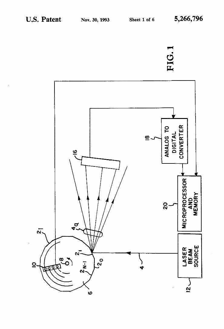
BRIEF DESCRIPTION OF THE DRAWINGS FIG. 1 is a schematic block diagram of an encoding
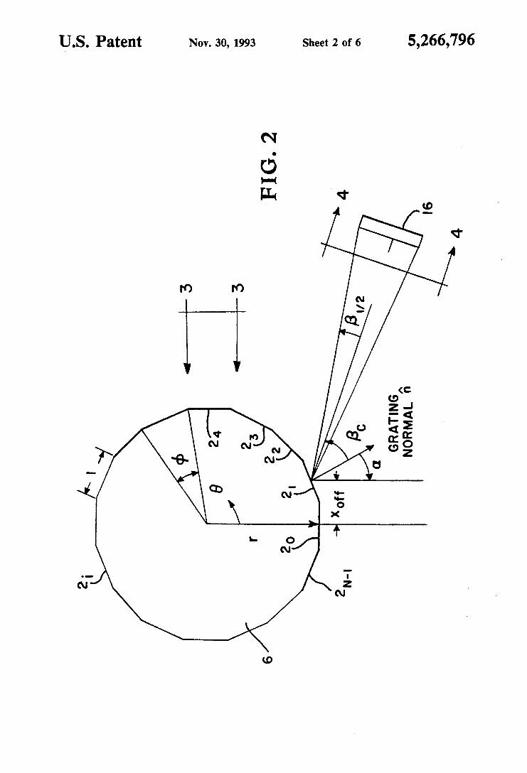
device according to the present inventive concepts. FIG. 2 is a detail view of the geometry involved in
the encoding device shown in FIG. 1. FIG. 3 is a detail view along lines 3-3 of FIG. 2. FIG. 4 is a detail view along lines U of FIG. 2. FIG. 5 is a graph of the geometric sensitivity enve-
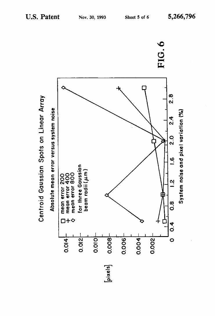
FIG. 6 is a graph of the mean error in determining
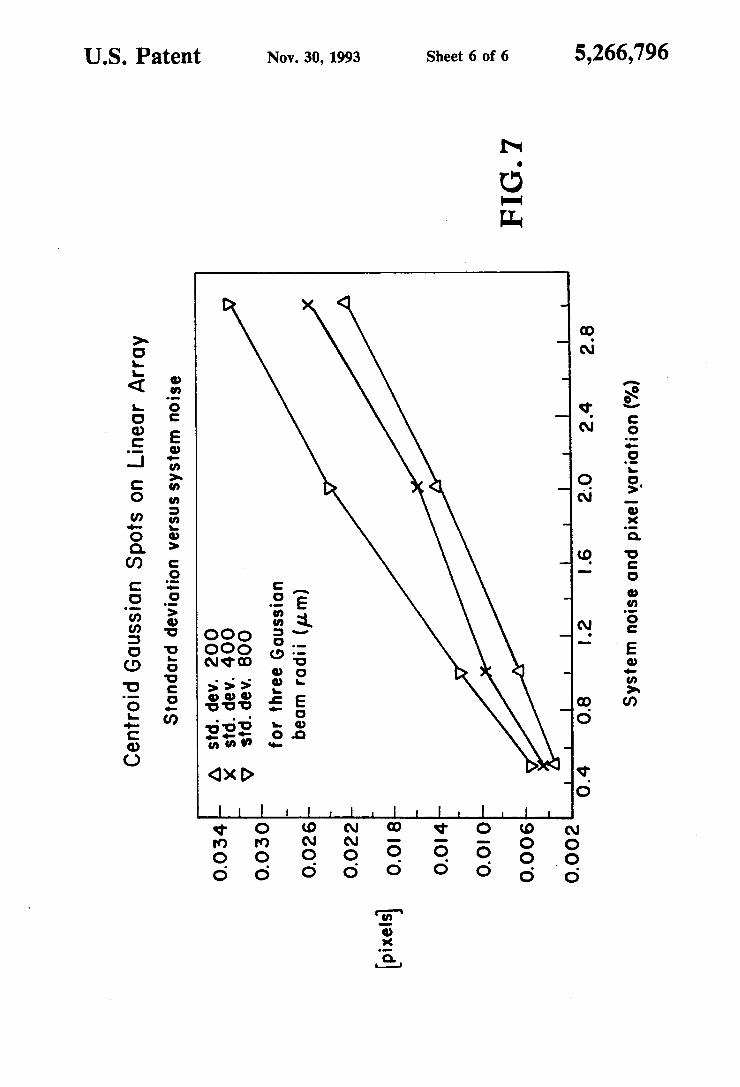
FIG. 7 is a graph of the standard deviation in deter-
lope for a representative encoder design.
spot locations.
mining spot locations.
DETAILED DESCRIPTION OF THE INVENTION
My inventive encoding device is a combination of several recent innovations in optical and electro-optic technologies. These components and their important characteristics are listed below. To see how the compo- nents are implemented in the device, refer to the func- tional block diagram (FIG. 1) and the discussion that follows under Principles of Operation for the Encoding Device.
Monochromatic light source 12 is a compact HeNe gas laser or solid state laser (e.g., laser diode-pumped, frequency-doubled Nd:YAG or Nd:YLF) which emits beam 4 can be delivered by a small diameter fiber optic cable. Light source 12 is thus monochromatic, compact, reliable, and affordable and is directed in the form of a small diameter beam 4 with low divergence at polygo- nal mirror 6 which acts as an optical substrate for a multi-faceted diffraction grating, available with very small facet angle errors (subarcsecond) and excellent ontical flatness on facets 21-2w. Attached to Dolvaonal
50 mirror 6 is a 4 bit binary 0; Gray code encoder io' (for facet 2j identification) which is simple, reliable, estab- lished and well-understood technology.
A low line density diffraction grating is on each facet 2i0f polygonal mirror 6. The diffraction grating is iden-
55 tical on every facet 26 can be patterned holographically for perfect groove periodicity, patterned by photoli- thography through a mask, or replicated from a blazed mechanically ruled master if higher diffracted effi- ciency in desired orders is required.
Position sensitive detector 16 can be a CCD array detector having a linear array of a large number of diodes (200-8000) with very small pixels (7-15 pm) providing high speed/photometrically linear and uni- form response to monochromatic light beam 4 provided
65 by laser 12, and has high electronic throughput and is reliable. Detector 16 could also be an area array detec- tor. Connected to detector 16 is 12+ bit analog-to-digi- tal converter 18 to read out the linear array of diodes in
60

5,266,796 3
detector 16. A floating point microprocessor 20 with double precision math processing capability and mem- ory to hold and manipulate array detector 16 data is used and will compute shaft 8 angle absolutely based on information from facet identifying encoder 10, and posi- 5 tions of diffracted light spots on linear array detector 16. Microprocessor 20 is currently available in many forms with high speed and reliability and more than adequate computing capacity.
phisticated components, the operation of the device will actually be rather simple and reliable as discussed be- low.
Although the encoding device employs several so- 10
PRINCIPLES OF OPERATION OF ENCODING 15 DEVICE
The operation of the encoder relies on the analyti- cally established, non-linear behavior of the angles of diffracted light beams 40 (orders) from a diffraction grating 22 (FIG. 3) as the angle of incidence of light 20 beam 4 on grating 22 is varied. The classical equation governing this behavior is the famous “grating equa- tion” and is expressed as follows (Eq. l):
mA/d=sin a+sh fi 25
where m is an integer (order number), A is the wave- length of light, d is the distance between adjacent grooves 24 of grating 22 (here I are assuming that all grooves 24 are straight, parallel, and equally spaced), a 30 is the angle of incidence of light beam 4 with respect to the normal to grating 22 surface, and @ is the angle from that normal into which light beam 4 diffracts for the given order m.
for conceptual reasons only, I assume two simple things: first, that light beams can be thought of as geometric rays; and second, that the first time we see the situation in FIG. 1, shaft 8 angle 8 is such that incident light beam 4 is just intersecting the upper right end of facet 40 21. I will begin by considering counterclockwise shaft 8 motion (positive sense for e). Thus, incident beam 4 from light source 12 in FIG. 1 will seem to creep down facet 21, changing its angle of incidence on facet 21, as shaft 8 rotates. 45
The basic, observable phenomenon in this system will be spots of light on linear array detector 16 where dif- fracted beams 40 (orders) intersect the line segment in space which is the linear array. At any instant in time, shaft 8 angle information is in fact determinable by the 50 exact locations of these spots on the linear array, i.e. the intersections of rays 4a with the line segment.
To see why this is so, consider the following: as shaft 8 (and polygonal mirror 6) rotates through an angle A e , the angle of incidence a of monochromatic source 12 55 light beam 4 with respect to facet 21 normal changes by Aa, which is exactly =A@, which causes the angular distribution of the diffracted light beams 40 to change. Two crucial things happen to the light spots on the linear array detector 16. First, they move. They do so in 60 such a way as to continue to satisfy the grating equation which is related to the second thing. Due to the non-lin- ear nature of the grating equation, the distance between the spots changes. It is this aspect of the encoder’s be- havior which distinguishes it from incremental encod- 65 ers and allows it to uniquely identify a shaft 8 angle within the angular range defined by the intersection of the incident source beam 4 and any identical facet 2i.
To begin the description of the encoder’s operation, 35
_ -
4 The behavior just described continues until the next
facet & comes around, at which point the behavior repeats itself. The desired behavior is called “modulo 27r/N,” where N is the number of facets 2i0n polygonal mirror 6 and 27r/N is called the “sector angle” in radi- ans. The absolute shaft 8 angle is obtained by knowing the angular offset for the illuminated facet 2 and adding the uniquely defined angular component governed by the grating equation and manifested in the locations of light spots on the linear array detector 16. The angular offset is simply the facet 2i number times the sector angle, where facets 2; are numbered 0 through N- 1. The angular component depending on the grating equa- tion is computed from knowledge of the gratings’ line density (inverse groove 24 spacing d), source 12 wave- length h, and geometric concerns which are assumed to be invariant. These geometric aspects are polygonal mirror 6 dimensions, linear array 16 placement, and offset distance from shaft 8 center where incident beam 4 strikes polygonal mirror 6, defined as hfi
To complete the description of the overall system, the location information of the light spots on array detector 16 is read from array 16 by conventional means through analog-to-digital converter 18 under the con- trol of microprocessor 20 into microprocessor 20 mem- ory. Once the information is in memory, it is processed or otherwise manipulated to determine shaft 8 angle through the implementation of appropriate algorithms and stored calibration data. This process can be carried out continuously many, many times per second.
CONSIDERATIONS FOR DEVICE ACCURACY, RESOLUTION, AND SENSITIVITY
Accuracy, resolution, and sensitivity are important aspects of the encoder. These aspects are influenced by a number of things (though not necessarily the same things). Resolution and sensitivity, which will be used somewhat interchangeably, are related terms in this context but with a subtle distinction. Encoder sensitiv- ity is the degree to which a change in shaft 8 angle A e can be sensed. For this encoder, sensitivity is a function of shaft 8 angle. The term resolution will be used when speaking of the geometric properties of the encoder which in part determine sensitivity but are independent of shaft 8 angle.
FIG. 2 is a detail view of the geometry involved in the encoding device shown in FIG. 1. First, I will de- scribe polygonal mirror 6. Its two chief attributes are the number of facets 2i, N, previously described, and what I will call facet 2iradius, r, which is the perpendic- ular distance from the center of polygonal mirror 6 (and shaft 8) to the center of any facet 2;. The previously described sector angle will be called 4. Facet 2i length will be called “1” and is computed as (Eq. 2):
’ = 2 tan;.$/2)
Next, I will describe the line density of grating 22 as n, in lines per mm. n is the reciprocal of d, the line spacing, described earlier. When n is used in a computa- tion with the wavelength h expressed in pm, it is in- verted and multiplied by loo0 so that the resulting num- ber will also be in pm. I turn next to detector array 16 (see FIG. 4) whose pixel dimension p along the array is typically in the range from 7 to 20 pm. The array length a is then simply the number of elements e times p. This is most conveniently expressed in mm. Laser beam 4

5 5,266,796
6 diameter b will also be described in mm. The beams will either be Gaussian in profile as from a laser or formed from a spatial filter/collimator arrangement and will likely be diffraction limited. In either case, I will assume that beam 4 will be of Gaussian type, where b will refer 5 to the diameter of beam 4 at its l/e power points. The details of the spatial distribution of beam 4 irradiance are not important as long as the distribution is invariant for each order 4, as it traverses array detector 16.
encoder geometry. I begin by considekg shaft 8 angle 8 to be zero when facet number 20 is horizontal and facing the bottom as shown in FIG. 2. Again, the angle of incidence a of laser beam 4 on a facet 2;is relative to that facet’s surface norma1 and depends on two things: Ones the quantity I referred to earlier as hffwhich is a
kg the Offset distance from shaft center where beam 4
Vibration will affect instantaneous resolution, but in a way which, is common to all sensitive encoding de- vices. As such, vibration is outside of the scope of this disclosure.
ACCURACY As with any device, there are a characteristic set of
things which will affect the encoder system accuracy. However most of these can be taken care of in a calibra-
Finally, I turn to the angular relationships of the 10 tion program. The other light in which to view the question of accuracy is “what might happen to change the calibration?”
The things that affect accuracy which can be Cali- brated at the system level are: thermal/mechanical changes, distortions due to assembly, facet 2; flatness, phase accuracy of grating 22 l ine across each facet 2;,
errors, variations in the array photoresponse, and elec- fractional quantity normalized to facet tiradius describ-
strikes polygonal mirror 6; and two, 8 itself. The two
howledge of dimensions, howledge of facet 2,. angle
tronic conversion of light information. Other describe the placement Of linear photodiode array l6 with respect to polygonal mirror 6. One
in this geometry, with Gfi uniquely zo
is
An ordinary spectral line emission lamp 12 such as a low pressure Hg lamp used with a narrow-bandpass filter (or some other of wavelength selector such as a the “center A” Pc, defined as the angle between facet 2;
incident beam 4 strikes the center of any facet 2j. This 25 defines a direction along which array 16 can be adjusted closer to or farther from polygonal mirror 6. The other angle is called the “beta halfrange,” pi, which describes
seen from the center of facet 2j when incident beam 4 30 to function properly. strikes the center of facet 2i. This angular subtense
by Pc.
prism or grating) or gas laser such as the HeNe
ple, emission wavelengths from these will be constant to a very high degree. While laser 12 source can have very narrow emission linewidths, a lamp’s spectral line-
and the perpendicular bisector Of array l6 when laser, is the preferred type of light source 12, In p,inci-
the angle subtended by one-half of array 16 length as widths be narrow for the encoder
If light source 12 is a solid state laser, system accu- places array 16 at a unique position on the line described racy be most affected by de-
pendence of light source 12 spectral emission, i.e. d)r/dT. Thermal dependence of spectral emission for a
35 solid state laser 12 might be essentially eliminated with RESOLUTION AND SENSITIVITY From FIG. 2, it is reasonably clear that the following
things will place an upper bound on the angular resolu- tion of the encoding device. These are: the beta half-
adequate control of laser 12 and/or corn- pensated for by the added system complexity oftemper- ature sensing and computational compensation. Ther-
range pi, the number of array 16 elements e, the pixel mal dependence of light source 12 spectral emission will size p, and, to a less obvious degree, beam 4 diameter b. 40 be discussed in more Other things which will affect the sensitivity of the Most, if not all, of the previously mentioned aspects encoder in such a way as to enhance it but which are not can be minimized by appropriate component specifics- evident from FIG. 2 are: the ability to accurately tions to a degree which might obviate calibration alto- pute the centroid ]ocations of individual spots from gether. Such specifications might include: suitable opti- digitally converted array 16 data, the ability to compute 45 cal flatness on Polygonal mirror 6 facets 2i3 materials
simultaneously on array 16, multiple sampling (average expansion, incorporation of a temperature sensor allow- ing) of light spot location data, and processing for ing thermal compensation to be implemented, etc. redundant/additional channels with added computa- Mounting distortion Can not be calibrated OUt unless tional constraints. 50 calibration is performed after mounting which may not
The least obvious but perhaps most important factor always be feasible. According to experts in the rota- is the photometric accuracy with which light spots can tional encoder industry, the ultimate limitation of an be digitally converted by the system. The photometric mcoder is its bearings and shaft 8 coupling. Again, accuracy can be increased (but not without limit) by these mechanical aspects of encoder design are not multiple sampling but at the expense of system band- 55 within the scope of this disclosure. Here, I am con- width. This will be addressed later under analysis of cerned only with the aspects of encoders from which performance. angular information is derived. It is, however, interest-
One other subtle thing is not obvious from FIG. 2. In k g to note that the operating principles of this device order to compute the difference in location for orders may make it intrinsically relatively immune to the type 4, on array 16, there must be at least two orders 4, on 60 of mechanical mkalignments which plague conven- array 16 at all times. This drives the choice of line den- tional rotary encoders, e.g., non-concentricity or tilt of sity n which is coupled to the other parameters, Pc and shaft 8 and encoder and shaft 8 wobble. &. The latter three parameters are most easily selected These are a few things which can affect the size of the using a specialized computer program. Also, due to the diffracted spots on array 16 which in turn can be cali- non-linear behavior of the grating equation, sensitivity 65 brated out. These are the raw beam 4 size from light is not constant over any angular range but has a lower source 12, the number of illuminated grooves 24 on bound for some point in the range of angles of incidence gratings 22 coupled with the line density of gratings 22, encountered for each facet 2;. facet 2; flatness, light source 12 emission linewidth (dis-
later.
the difference in centroid locations for all pairs of spots with suitable stiffness and low coefficient of thermal

7 5,266,796
8 cussed later) and the other optical properties of an ancil- lary beam shaping optics which might be employed.
ANALYSIS OF PERFORMANCE Because light source 12 and detector array 16 are
fixed with respect to each other, and polygonal mirror 6 rotates with respect to these, the positions of the dif- fracted orders 4, on array 16 are related to the differ- ence between the incident and diffracted angles, i.e. to 8-a. The geometric angular sensitivity of the situation is directly related to the rate of change of this difference for a given order m with respect to incident angle a, specifically to the derivative d@-a)/da. Eq. 1 rear- ranged and solved for p gives (Eq. 3):
B=arcsin(mA/d--sin a)
Then, d@-a)/da is given by (Eq. 4):
= -wsa [l - (mA/d - sinaY1-i - 1
From this equation, I can make a few observations about which source 12/polygonal mirror 6/array 16 placements will be advantageous. For the zero order diffracted beam 4, (the order which behaves as the ordinary, mirror-like or specular reflection), eq. 4 evalu- ates to -2 for all a. This is consistent with Snell’s law of reflection and the familiar “28 deflection” law for specular reflections. The minus sign is consistent with the standard sign conventions for a and p in the grating equation. For orders near zero order, this “sensitivity” remains near -2. What does it take for Eq. 4 to tend to a maximum’? The cos a term is largest when a is around 0. Eq. 4 will also tend to be maximized when the radical, being in the denominator, becomes small. This occurs when the term mh/d-sin a approaches unity. But this latter term is exactly sin from Eq. 1. Sin p approach- ing unity means that the diffracted light 4a comes off grating 22 nearly tangent to the surface or at “grazing” angles. For a=O, this occurs for increasing order num- bers. The nonlinearity of Eq. 4 increases dramatically for larger orders and for near-zero a’s. The choice of incident angle is rather a choice of a range of incident angles which gives good angular sensitiity over the entire angular range defined by a facet 2i.
What I currently believe to be a good set of baseline encoder parameters is: 00% radial offset ( h f / = O ) of the incident beam from polygonal mirror 6 axis, 20 li- nes/mm gratings 22, 16 facets 2i, p4=5.O0 and A=0.532 pm. These parameters are not optimal choices but are suitable for illustrating these claims. This design was used in a study of system angular sensitivity and the effect of source 12 spectral emission variations. The linear array 16 in this design in an Eastman Kodak de- vice with 8000 pixels which are 9 pmX9 pm in size. The geometric angular plate scale on array 16 is 4.5 ”arc/pixel.
Equation 4 has been used to compute a “geometric sensitivity envelope” for this baseline design. Remem- ber that d(P-a)/da, or equivalently d(P-a)/de, is a dimensionless number which describes an angular am- plification of deflection of diffracted beams 4, relative to the incident beam 4. This computed envelope is shown in FIG. 5. For this design a ranges from - 11.25” to + 11.25’. For a’s between -11.25” and o”, the geo- metric sensitivity or amplification is between about 3 and 5 . For a’s at the upper end of the range, the amplifi-
cation takes on values in excess of 7 and sometimes as high as 14 to 20!
Resolution is defined as the geometric, angular incre- ment corresponding to the minimum resolvable dis-
5 placement of a light spot on linear pixel array detector 16. It turns out that its upper limit is established by the angular subtense of a pixel as seen by the point on a polygonal mirror 6 facet 2i where source 12 beam 4 is incident, i.e. by 2&/e. Obviously, resolution is en-
10 hanced by having as many pixels of the least size possi- ble in linear array 16. It is also enhanced by having as small a beta halfrange as possible. These two things means longer baselines for diffracted beams 4@ Longer baselines can be accomplished simply by folding beams
15 4a around within the package with flat mirrors to main- tain a rigid, compact device. These geometric concerns affect array 16 placement. Also, remember that ulti- mately, array 16 placement depends on the constraint that there must always be at least two orders 4a on array
Due to the ability to compute the centroid of the light distribution of a spot on the pixels of array detector 16, resolution can be extended well below the single pixel level. A simulation was performed to study CCD array
25 16 subsystem’s capabilities in this regard. The simula- tion accounted for the following effeckbeam 4 shape and size and irregularities therein, pixel-to-pixel photoresponse variation, system conversion noise, and repetitious sampling. In the simulation, a photoresponse
30 for each array 16 pixel was chosen randomly within selectable prescribed limits. A target location for a per- fect Gaussian profile was randomly chosen to fall some- where on array 16. Then a Gaussian, whose half-width is selectable but whose pixel value at each pixel is ran-
35 domly perturbed by some noise factor within selected limits, was computed along with its effective centroid location and error relative to the foreknown target Gaussian center. If multiple samples have been speci- fied, the average of that number of samples is consid- ered to be the result. This was repeated one hundred times for each set of prescribed limits. Mean error, vari- ance, and standard deviation were then computed for the one hundred samples.
The simulation was parameterized as follows. Three 45 different Gaussian spot sizes (diameters) were tried: 0.40
mm, 0.80 mm, and 1.6 mm diameters. Four different combinations of system noise and pixel-to-pixel varia- tions were tried for each spot size. With one exception, two different numbers of samples-1 and 3-were tried
50 for each combination of system noise and pixel-to-pixel variation. The parameterization is tabulated in Table I.
20 16 at any instant in time.
TABLE I
Noix (%) Variation samples 55 System Pixel-to-pixel
3 2 1 3 2 4 2 1 1 2 1 3
I 1 3 0.5 0.5 1 0.5 0.5 3
60 1 1 1
65 The results for means error and standard deviation in pixels for single sample simulations are shown in FIGS. 6 and 7 respectively. The results indicate the two obvi- ous things one would expect: that performance im-
5,266,796 10
0.005[pixels] x 4.5["arc/pixe1]/3 =O.a)75["arc]. 9
proves for 1) lower system noise and lower pixel-to- pixel variation and 2) smaller spot sizes. CCD experts believe that in practice, pixel-to-pixel variations and (at some angles, the sensitivity would be as small as system noise can be systematically reduced to less than about 0.002 "arc) 0.5% each. This immediately focusses attention to the 5 A more rigorous method invokes the use of a special- left-hand part of the figures. Even for the largest spot ized computer Program and a simple study of how size studied, 1.6 mm Gaussian diameter, the mean error many Pixels are traversed as shaft 8 rotates through one and standard deviation are only several millipixels. TO unit of angle. For example, a value for order number be conservative, I believe 0.005 pixels is an achievable 112 of 6 Pixels per 1 "arc change in shaft 8 angle was number for centroided pixel resolution. n s SSUmes 10 derived. The actual value of shaft 8 angle is held in this one can get a spot size under 1.6 mm diameter. Note instance in the differences in pixel locations for the pairs that this value is not inconsistent with routine centroid- of orders 110 and 111, 110 and 112, and 111 and 112. b g capabilities for area CCD arrays with light spots Relying only on difference information, We get a WnSi- only several pixels wide (which makes centroiding con- tivity of 4.7 pixels per 1 "arc change in shaft 8 angle. siderably less certain) where 0.01-0.02 pixel certainties 15 Coupled with the ability to determine spot location to in centroid are achieved. the 5 millipixel level, an angular sensitivity of 0.005
I will now discuss what spot size to expect. Assumed Pixels15 Pixels per 1 "arc change in shaft 8 angle Or is the use of a compact HeNe laser 12 with an exit spot 0.001 "arc sensitivity is available. diameter of 0.7 mm and a beam 4 divergence of 1 mrad. Compare these values with the state-of-the-art, con- This design has a total path length roughly 0.4 m. This 20 ventional optical encoder which is 26 bit resolution or distance combines with beam 4 divergence to increase 0.02 "arc. According to NIST's Angular Measurements the spot size from 0.7 mm to 0.7+400~0.001= 1.1 mm Laboratory the NIST angle calibration machine is not which is well less than 1.6 mm. The other thing which Currently but Will Ultimately be good to 0.003 "arc. The can increase the spot size is the diffracted angular range encoding device disclosed here can thus Yield a 10-20 associated with
OTHER CONSIDERATIONS way that range changes with increasing order number. With appropriate intracavity optics, a gas laser 12 can
have an emission linewidth far than its D ~ ~ - The situation previously described where the next broadened gain curve, characteristic of the facet 2; presents itself to the incident source 12 beam 4
excited gas in the plasma tube. so, to consider 30 was intentionally oversimplified. In reality, there will be
minated and there will be two sets ofspots on array 16 simultaneously. While it seems as if this might be an uncomfortable situation, this behavior will be not only
35 trivial for microprocessor 20 to hand.e, but will in fact be advantageous in a calibration sense when the bound- ary conditions of equality of rate of change of shaft 8 angle with computed incident angle (dWda) is en- forced for both sets of spots. Alternatively, with the
40 addition of a second source 12Ainear array 1VA-to-D converter 18 channel, the simultaneous facet 2;situation can be averted with the added advantages of redun- dancy in the case of a failure in one channel and addi- tional accuracy with the imposition of further boundary
45 conditions associated with the existence of that second channel.
While the lower limit on the number "N' of facets 2 ~ i s three, there is no intrinsic upper limit for N. How-
Here, the corre$ponding wavelength spread turns out ever, there are some practical concerns which lead to an to be about 0.02 A. How wide then would a source 12 50 optimum choice for N. The fewer facets 2jthere are, the linewidth have to be to see an increase in spot size of 0.5 fewer facet-to-facet angle errors must be kept track of. mm diameter in the design? If we calculate /3-a for the This must be balanced against the desire to assign as highest order at the edge of array 16 for this wave- little angular range to a given facet 2;as possible (mini- length, then dither the wavelength slightly, we get a mize the sector angle +) so that the number of orders on slightly different /3-a which means a slightly different 55 array 16 does not vary wildly as the incident beam 4 spot locationoon array 16. It takes a wavelength spread traverses the entire facet 2;. Finally, it is convenient to of about 1.3 A (or over 60 times the Doppler broadened have a number of facets 2;which is a power of 2 so that linewidth) to cause the diffracted spot to grow by 0.5 facet 2; identification can be done with a simple, pig- mm to 1.6 mm diameter. This means that emission 4 gybacked, binary encoder. Based on studies, it turns out linewidth for even an ordinary gas line source 12 is not 60 that 8, 12, and 16 are good choi,ces for number "N' of an issue to system performance. facets 2; with 16 being an optimum.
I will now discuss the encoding device's angular Adding additional source 12/detector 16 channels sensitivity. A rough method for computing encoder can provide several advantages. Multiple independent sensitivity is by equating sensitivity to the centroided samples offer improved certainty of angular, determina- pixel resolution times the geometric angular plate scale 65 tion, possible self-calibration, redundancy in the event divided by the geometric sensitivity developed above. of a failure of one channel, and some degree of immu- Substituting the worst case numbers gives: nity to defects in one or more facets 2;or in one particu-
lar linear array 16. The disadvantages of multiple chan-
12 linewidth and pafiicularly the 25 fold increase in angular sensitivity or resolution.
the Worst case, 1 shall compute the line width and corre- a small range of angles where two facets 2; will be i h - spending spot size for ~~~~l~~ broadened emission from, say, gas. The linewidth in frequency space for a gas species whose atomic and temperature T [K] is:
is M
where v is the oscillation frequency [I/s], c is the speed of light (3 X 10Sm/s), and k is Boltzmann's constant. For neon gas (M=20) at 400" K. (100" c.), the linewidth is about 1.3 x 10⁹ Hz. Frequency linewidth and wave- length linewidth are related by the expression:
AA= -A2.Av/c
11 5,266,796
12 nels are slight increases in data storage requirements and computational/operational complexity, and a slight decrease in system conversion bandwidth.
With regard to vibration, it is possible that the encod- ing device could also the vibration environment in which it is used. This would be done either through time-averaged or even time-resolved computations on spot shape perturbations measured from the linear array 16.
such a device, it is interesting to note that the device chromated by optical itself has intrinsic features which will allow it to be used 6. The device of claim wherein said monochromatic with substantial accuracy without calibration. Further- light beam is directed towards =id facets by a fiber more, it is possible that the device might find applica- optic cable employing beam shaping optics, tion as either a secondary Or perhaps even Primary 7. The device of claim 1 wherein said low line density angular calibration standard. diffraction grating is patterned holographically on said
To those skilled in the art, many modifications and facets. variations of the present invention are possible in light 8. The device of claim 1 wherein said low line density of the above teachings. It is therefore to be understood 20 diffraction grating is patterned by replication from a that the present invention can be practiced otherwise blazed mechanically ruled master on said facets. than as specifically described herein and still will be 9. The device of claim 1 wherein said low line density within the spirit and scope of the appended claims. diffraction grating is patterned by photolithographic
means involving a mask.
sity diffraction grating is patterned by a molding pro-
about its axis of rotation based upon the data from said analog-to-digital converter means.
2. The device of claim 1 further including a binary code encoder affixed to said polygonal mirror for iden-
3. The device of claim 2 wherein said monochromatic
4. The device of claim 2 wherein said monochromatic
5. The device of claim 2 wherein said monochromatic
used to give infomation about 5 tification Of One Of said plurality Of facets.
light beam is emitted by a gas laser.
light beam is emitted by a solid state laser. 10 it can be advantageous to light beam is emitted by a gas source and suitably mono-
or dispersion.
I claim: 1. A device for encoding the angular displacement of 25 10. The device of claim 1 wherein said low line den-
a rotating shaft about its axis of rotation comprising: a polygonal mirror having a plurality of facets
thereon affixed to said shaft; a monochromatic light beam directed towards said
facets; said facets of said polygonal mirror each having a low
line density diffraction grating patterned thereon to diffract said monochromatic light beam into a plu- rality of diffracted light beams such that a plurality 35 of light spots are created on a position sensitive detector means;
an analog-to-digital converter means connected to said detector means for reading the position of said spots on said detector means;
Processing and memory means connected to said analog-to-digital converter means to hold and ma- nipulate data provided by said analog-to-digital converter means on the position of said spots and to
30
Ih. The ievice of claim 13 wherein said plurality of diodes is in the range of 200 to 8000 and said pixel size is in the range of 7-15 pm. 15. The device of claim 1 wherein said polygonal
mirror has a number of facets thereon which are a power of 2. 16. The device of claim 15 wherein said polygonal
mirror has 16 facets thereon.
40
compute the angular displacement of said shaft 45 * * * * *
cess. 11. The device of claim 1 wherein said position sensi-
tive detector means comprises a linear array detector means. 12. The device of claim 1 wherein said position sensi-
tive detector means comprises an area array detector means. 13. The device of claim 11 wherein said linear array
detector means contains a large plurality of diodes with verv small Dixel size.
50
55
65


![I 1111111111111111 11111 1111111111 1111111111 1111111111 ... · I 1111111111111111 11111 1111111111 1111111111 1111111111 lllll 111111111111111111 US006080401A [11] Patent Number:](https://img.dokumen.tips/doc/110x75/614285c4d9e4dc11f47f1ad9/i-1111111111111111-11111-1111111111-1111111111-1111111111-i-1111111111111111.jpg)