Embed Size (px)
Citation preview

Operating Instructions, Installation & Maintenance Manual
M o d e l E V M U
EBARA Fluid Handling EBARA International Corporation
Stainless Steel Vertical Multistage

EBARA Stainless Steel Vertical Multistage EVMUInstructions and Operation
EBARA Fluid Handlingwww.pumpsebara.com 2(t) 803 327-5005 • (f) 803 327-5097 rev. 11/05
Manufacturer Information
Sectional view – part no.s (refer to page 2 for sectional view)
Section PageManufacturer Information 1
Component Identification Drawing 2
1 – General Information and Warnings 3
2 – Specifications 3
3 – Pump Checks & Installation 4
4 – Operation 6
5 – Maintenance and Service 7
EBARA Fluid Handling1651 Cedar Line DriveRock Hill, SC 29730
Phone: 803-327-5005Fax: 803-327-5097
e-mail: [email protected] site: www.pumpsebara.com
005/1005/2005/3005/4006007011021031
039/1040
043/1043/2043/3043/4043/5046/1046/2048052056070
Intermediate casing suctionIntermediate casingIntermediate casing bearingIntermediate casing dischargeBottom casingOuter casingCasing coverImpellerShaftKey (pump shaft)Bearing sleeveShaft sleeve (mechanical seal)Shaft sleeve (intermediate)Shaft sleeve (bearing)Shaft sleeve (last stage)Shaft sleeve (adjustment)Split ring (shaft end)Split ring (mechanical seal)U-NutBearingBall bearingRing Holder
AISI 304AISI 304AISI 304AISI 304AISI 304AISI 304AISI 304AISI 304AISI 304AISI 304Tungsten carbideAISI 304AISI 304AISI 304AISI 304AISI 304Carbon tool steelsAISI 304AISI 304Tungsten carbide–AISI 304
1111111111111111111111
Part Part Material No. forNo. Name 1 Unit
107111
115/1115/2120/1120/2128130135137140150160162212
245/1245/2274/1274/2274/3274/4
Liner ringMechanical sealO-ring (outer casing)O-ring (intermediate casing)BoltCasing boltNut (casing bolt)ScrewWasherSpacerCouplingSpacerBaseMotor bracketPlugCoupling guardCoupling guardC-type snap ring (coupling)C-type snap ring (bracket)C-type snap ring (shaft end)C-type snap ring (mechanical seal)
AISI 304/EPDMSic/Carbon/FPMVitonEPDMCarbon steelSteel chromateSteel chromateAISI 304SteelAISI 304Carbon steelCarbon steelCast ironCast ironAISI 304/TeflonAISI 304AISI 304Carbon tool steelsCarbon tool steelsCarbon tool steelsAISI 304
112114444111113111111
Part Part Material No. forNo. Name 1 Unit

EBARA Stainless Steel Vertical Multistage EVMUInstructions and Operation
EBARA Fluid Handlingwww.pumpsebara.com 3(t) 803 327-5005 • (f) 803 327-5097 rev. 11/05
Component Identification Drawing
2741
2452
0431
0462
0434
0432
0432
2744
0435
0391
2451
150
031
070
021
040
048
006
1202
1151
0051
0053
1152
1151
1201
2743
2742
0461
0052
0054
180
212
052
107
007
135
128
130
140
056
162
137
011
111
212
Note: Refer to facing page (page 1) for identification of part numbers.

EBARA Stainless Steel Vertical Multistage EVMUInstructions and Operation
EBARA Fluid Handlingwww.pumpsebara.com 4(t) 803 327-5005 • (f) 803 327-5097 rev. 11/05
1.2 Before any work is performed on the EVMU pump care should be taken to ensure that electric power is disconnected to the motor to prevent electric shock or prematurestarting which could cause damage to persons, things or the pump.
1.3 Before starting the EVMU pump, make sure that all cables, electrical connections and controls are in perfect working order and properly grounded. Improper installationcan result in serious or even mortal accidents to persons.
Any electrical work should be preformed by a licensed electrician.
Warning
Be careful not to exceed the given specifications in the use of your products.
1.1 The user must comply with all local and national regulations that apply to the installation and operation of electric pumps. Operation of the EVMU pump must be compatible with the construction of the pump as shown in the SPECIFICATION section of these instructions.
1.4 EVMU pumps with motor installed tend to be top heavy, care should be taken in handling and transporting to prevent damage or injury caused by the pump falling over.
Liquid handledType of liquid Clean waterTemperature 5° to +248°F (-15° to 120°C)Working pressure 230/360 PSI (16/25 Bar)
ConstructionImpeller Closed centrifugalSeal Mechanical shaft sealBearing Sealed ball bearing / tungsten carbideSuction/Discharge ANSI 250 lb 11/4'' 4 / 2'' 8 bolt flange
MaterialsImpeller AISI 304LIntermediate casing AISI 304LBottom casing AISI 304LCasing cover AISI 304LOuter casing AISI 304LShaft AISI 316Liner ring EPDM/AISI 304LShaft seal Silicon-Carbon-FPMMotor bracket Cast ironBase Cast ironTest standard ISO 2548 Class C
Motor NEMA C / TC frame
Specifications
General Information and Warnings
CAUTION!
!

EBARA Stainless Steel Vertical Multistage EVMUInstructions and Operation
EBARA Fluid Handlingwww.pumpsebara.com 5(t) 803 327-5005 • (f) 803 327-5097 rev. 11/05
3.1 Always check to make sure pump was not damaged in shipment before accepting delivery. If damage is evident, a claim should be filed with the carrier at that time.
3.2 Always check the pump label against the requirement to make sure you are installing the properpump specified for the job.
Model Designation
3.4 Make sure that the pump suction, marked by a sticker, is connected to the liquid source and that the discharge, similarly marked, is connected to the discharge line.
3.6 Make sure that the pump base is firmly secured to a solid flat surface and that the suction and discharge lines are aligned and properly supported to prevent pipe strain on the pump.
3.7 Ensure that the suction and discharge gaskets are properly installed to prevent leaks and that they do not restrict the flow to or from the pump.
Standard ANSI mating flanges should be used to connect the pump to the piping. Suction and
discharge piping should be no smaller than the respective pump port sizes.
EBARA VerticalMultistage (USA)
D=Open Drip Proof (ODP) T=Totally Enclosed Fan Cooled (TEFC)
EVMU 2- 2 F 0050 D 1 S Silicon Carbide/Carbon Mechanical Seal
1=Single Phase 3=Three Phase
Nominal Size
Number of Stages
Flanged Connections
Horsepower
0050=1/2 HP 0500=5.0 HP 0075=3/4 HP 0750=7.5 HP 0100=1.0 HP 1000=10 HP 0150=1.5 HP 1500=15 HP 0200=2.0 HP 2000=20 HP 0300=3.0 HP 2500=25 HP
3.5 On three phase motor installations, always check for proper motor rotation prior to starting byjogging the motor. Shaft rotation must turn clockwise when viewed from the back of the motor.
Make sure the motor is correctly wired, refer to instructions on motor name plate.
Pump Checks
CAUTION!

EBARA Stainless Steel Vertical Multistage EVMUInstructions and Operation
EBARA Fluid Handlingwww.pumpsebara.com 6(t) 803 327-5005 • (f) 803 327-5097 rev. 11/05
3.8 Isolation valves should be installed on both the suction and discharge side of the pump in the event service of the pump is required.
3.9 Provide adequate space and ventilation around the pump for service and motor cooling.
3.10 Use standard plumbing practices to ensure unnecessary line losses, cavitation and prevent air lock.
Installation3.11 Completely prime the pump by removing the vent plug (212), remove the coupling guard where
necessary.
Using a funnel, fill the pump body with water until it overflows and replace plug.
Alternatively for installations with positive suction heads, close the discharge valve and remove the vent plug.
Open the suction valve until liquid flows out of the vent plug opening and then replace the vent plug securely and open discharge valve.
Replace coupling guards if previously removed.
3.12 It is recommended that a bleed valve be installed in discharge line or in a line from the vent port to the reservoir. This will allow the pressure in the pump to be relieved for service.
Installing a bleed valve is especially necessary in hot water applications to prevent injury.
3.13 Pipe, valves and fittings must have a pressure rating equal to or greater than the maximum system pressure.
EXTREME CAUTION SHOULD BE USED IF PRIMING THE PUMP IN THIS MANNER IN A HOTWATER APPLICATION.
OPERATING THE PUMP WITHOUT THE GUARDS IN PLACE CAN CAUSE PHYSICAL INJURY.
Pump Checks (cont.)
WARNING!
CAUTION!
WARNING!

EBARA Stainless Steel Vertical Multistage EVMUInstructions and Operation
EBARA Fluid Handlingwww.pumpsebara.com 7(t) 803 327-5005 • (f) 803 327-5097 rev. 11/05
3.14 A bypass or pressure relief valve should be installed in the discharge line if there is any possi-bility the pump may operate against a closed valve in the discharge line.
Minimum flow is required for proper cooling and lubrication of the pump without which, damage and premature failure will occur.
3.15 If the installation of the motor is necessary, refer to section 5.1 for instructions.
Minimum Pumping Rate
Model Minimum Flow RateEVMU 2 3.3 GPM
EVMU 4 6.7 GPM
EVMU 8 8 GPM
EVMU 16 11 GPM
Operation4.1 Make sure that the system is properly installed and primed as instructed in section 3.
4.2 Check that the suction valve is fully open and that the discharge valve is in its open position.
4.3 Check to make sure all electric connections are correct.
4.4 Apply power to the motor.
Check motor rotation.
Check that the noise, vibration, pressure, voltage and amps are at normal levels.
Prolonged operation of the EVMU pump with either valve in the closed position will cause severedamage to the pump.
4.5 EVMU pumps are designed for continuous and normal off/on operation.
RAPID CYCLING CAN CAUSE HIGH HEAT AND LOADING THAT CAN CAUSE DAMAGE TO THE PUMP OR MOTOR.
Pumps should not be starting more than the following rate:
20 times per hour on 1/2 to 5 HP models,15 times per hour on 71/2 to 15 HP models,10 times per hour on 20 and 25 HP models.
Installation (cont.)
CAUTION!
WARNING!
EBARA Stainless Steel Vertical Multistage EVMUInstructions and Operation
EBARA Fluid Handlingwww.pumpsebara.com 8(t) 803 327-5005 • (f) 803 327-5097 rev. 11/05
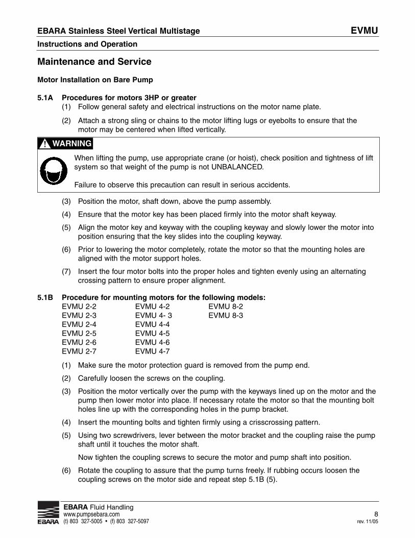
Motor Installation on Bare Pump
5.1A Procedures for motors 3HP or greater(1) Follow general safety and electrical instructions on the motor name plate.
(2) Attach a strong sling or chains to the motor lifting lugs or eyebolts to ensure that the motor may be centered when lifted vertically.
(3) Position the motor, shaft down, above the pump assembly.
(4) Ensure that the motor key has been placed firmly into the motor shaft keyway.
(5) Align the motor key and keyway with the coupling keyway and slowly lower the motor into position ensuring that the key slides into the coupling keyway.
(6) Prior to lowering the motor completely, rotate the motor so that the mounting holes are aligned with the motor support holes.
(7) Insert the four motor bolts into the proper holes and tighten evenly using an alternating crossing pattern to ensure proper alignment.
5.1B Procedure for mounting motors for the following models:EVMU 2-2 EVMU 4-2 EVMU 8-2EVMU 2-3 EVMU 4- 3 EVMU 8-3EVMU 2-4 EVMU 4-4EVMU 2-5 EVMU 4-5EVMU 2-6 EVMU 4-6EVMU 2-7 EVMU 4-7
(1) Make sure the motor protection guard is removed from the pump end.
(2) Carefully loosen the screws on the coupling.
(3) Position the motor vertically over the pump with the keyways lined up on the motor and the pump then lower motor into place. If necessary rotate the motor so that the mounting bolt holes line up with the corresponding holes in the pump bracket.
(4) Insert the mounting bolts and tighten firmly using a crisscrossing pattern.
(5) Using two screwdrivers, lever between the motor bracket and the coupling raise the pump shaft until it touches the motor shaft.
Now tighten the coupling screws to secure the motor and pump shaft into position.
(6) Rotate the coupling to assure that the pump turns freely. If rubbing occurs loosen the coupling screws on the motor side and repeat step 5.1B (5).
When lifting the pump, use appropriate crane (or hoist), check position and tightness of liftsystem so that weight of the pump is not UNBALANCED.
Failure to observe this precaution can result in serious accidents.
Maintenance and Service
WARNING!

EBARA Stainless Steel Vertical Multistage EVMUInstructions and Operation
EBARA Fluid Handlingwww.pumpsebara.com 9(t) 803 327-5005 • (f) 803 327-5097 rev. 11/05
5.2 Removing Motor from Complete Pump(1) Following general safety and electrical instructions, disconnect the power to the
motor and remove power cords.
(2) Loosen and remove the four motor bolts.
(3) Attach a strong sling or chains to the motor lifting lugs or eyebolts to ensure that the motormay be centered when lifted vertically.
(4) Slowly lift the motor off the pump assembly being careful to retain the shaft key. If the motordoes not slide easily out of the coupling do not raise the pump into the air, dropping the pump end can cause damage. Fix the pump base to the floor or bench and lift motor again.
5.3 Disassembly of pump for mechanical seal and hydraulic stack replacement
(1) Remove the motor as detailed in Section 5.2.
(2) Isolate the pump by closing isolation valves on the suction and discharge lines.
(3) Carefully relieve the pressure in the pump by opening the vent or drain plugs.
(4) Remove the vent plug (Part No. 212).
(5) Remove coupling guards (245) with Phillips head screwdriver.
(6) Using an Allen wrench (a T-handle is recommended) loosen and remove the pump couplingbolts (120/1) and remove the lower coupling section.
(7) Using 900 snap ring pliers, engage coupling snap ring (274/1) and lift up to clear end of thepump shaft.
(8) Loosen and remove four tie rods (120/2).
(9) Turn tie rods counter clockwise to loosen from pump base and remove. This will allow the solid coupling to clear the end of the shaft.
(10) Gently tap the base of the motor support with a soft mallet to loosen the fit.
For any removal or installation procedures, always disconnect the power first.
Failure to observe this precaution can result in serious accidents.
Extreme caution should be exercised in this operation since the pump is under system pressureat this point.
Use a pressure bleed valve in hot water applications where water temperature could causephysical injury.
Maintenance and Service (cont.)
WARNING!
CAUTION!

EBARA Stainless Steel Vertical Multistage EVMUInstructions and Operation
EBARA Fluid Handlingwww.pumpsebara.com 10(t) 803 327-5005 • (f) 803 327-5097 rev. 11/05
5.3 Disassembly of pump for mechanical seal and hydraulic stack replacement (continued)
(11) Turn the solid coupling half so that it is aligned with the vent pipe.
(12) Lift the motor support off of the pump assembly by tilting the support towards the vent pipe and lifting.
(13) Remove and retain the pump shaft key.
(14) Remove the seal plate (011 casing cover) vertically off of the pump shaft assembly.
(15) Remove the o-ring (115/1) from the top of the pump body (007 outer casing).
5.4 Replacement of mechanical seal.
(1) Complete disassembly of pump as detailed in Section 5.3.
(2) Remove the old rotating seal assembly by lifting vertically off the pump shaft. The rotating assembly is rubber boot mounted.
(3) Press the old stationary seal assembly out of the seal plate (011) from the outside of the seal plate. The stationary seat is rubber cup mounted.
(4) Place the rotating seal assembly retainer onto the shaft taking care not to scratch or touch the seal face. If touching the seal face is necessary, gently wipe with a clean soft tissue.
(5) Carefully place the rotating seal assembly onto the shaft using a non-metallic sleeve to push the assembly into place on the shaft, seating the rubber boot snugly.
(6) Using a non-metallic sleeve, press the stationary seal assembly into the seal plate (011) evenly, seating the rubber boot snugly.
(7) Reassemble the pump as instructed in Section 5.5.
5.5 Replacement of pump hydraulic assembly.
(1) Remove the old mechanical seal assembly as detailed in Section 5.4.
(2) Remove the pump body (007) from the pump casing and remove the o-ring located in the pump casing.
(3) Ensure that the proper replacement hydraulic (stack) assembly has been selected and provided for the applicable pump size.
(4) Lift the replacement hydraulic (stack) assembly and place it onto the pump casing (006) ensuring that it is firmly seated properly. Ensure that the pump shaft keyway is aligned vertically with the drain connection on the pump casing for ease of later assembly completion.
Maintenance and Service (cont.)

EBARA Stainless Steel Vertical Multistage EVMUInstructions and Operation
EBARA Fluid Handlingwww.pumpsebara.com 11(t) 803 327-5005 • (f) 803 327-5097 rev. 11/05
(5) Using a new lower pump body o-ring (115/1), apply a light film of lubricant such as Dow Corning #4, or similar, to the o-ring and place it over the hydraulic assembly and into the pump casing ensuring that it is seated.
(6) Place the pump body (007) over the entire assembly and align it with the o-ring installed into the pump casing. The tie rods will complete the seating of the pump body (007) into the pump casing.
(7) Using a new upper pump body lower o-ring (115/1), apply a light film of lubricant such as Dow Corning #4, or similar, to the o-ring and place it into the o-ring groove on the upper pump body (007) ensuring that it is seated.
(8) Replace the rotating mechanical seal mechanical seal assembly as detailed in Section 5.3 and 5.4.
(9) Replace the stationary mechanical seal assembly as detailed in Section 5.3 and 5.4.
(10) Carefully place the seal cover over the pump shaft ensuring not to damage the stationary seal face. Ensure that the vent pipe is vertically aligned with the with the drain connection of the pump casing.
(11) Install the pump shaft key into the keyway.
(12) Place the motor support onto the pump seal cover by tilting the assembly over the vent pipe. The solid coupling half must be turned toward the vent pipe to ensure that the pump shaft key will slide into the coupling keyway. The motor support should fit snugly onto the stationary seal assembly (011).
(13) Replace four tie rods, threading them into the pump mounting base.
(14) Replace the tie rod washers and nuts onto the tie rods finger tight.
(15) Commence staggered tightening of the tie rod nuts to ensure even distribution of pressure and proper seating of the seal cover plate onto pump body (007). Tighten all nuts to fit snugly.
(16) Place handle of soft mallet, or similar lever, into the pump suction so that the entire shaft may be raised slightly until the snap ring groove is above the lower lip of the pump coupling.
(17) With the pump shaft assembly lifted slightly, replace the pump shaft snap ring (274/3 or 046/1) until seated into the groove at the end of the shaft. This will lock the pump shaft into the coupling.
(18) Replace the lower coupling half and insert coupling bolts tightening them firmly. Ensure that coupling bolts are tightened evenly.
(19) Replace coupling guards and fasten with coupling guard screws tightening them evenly.
(20) Reinstall vent pipe plug.
(21) For reassembly of motor, see Section 5.1.5.1 - Installing the motor on a bare pump.
Maintenance and Service (cont.)

EBARA Fluid Handling1651 Cedar Line Drive • Rock Hill, SC 29730 (t) 803 327 5005 • (f) 803 327 5097www.pumpsebara.com© 2005 EBARA International Corporation EIC EVMU1011 0600
Contact your dealer or supplier for more information about other EBARA products: