Embed Size (px)
Citation preview

V5A51 - Valve Body 23E-11-1
11. VALVE BODYDISASSEMBLY AND ASSEMBLY
1
23
4
5
67
8
9
10
1112
13
1415
11 ± 1 Nm
14
13
11 ± 1 Nm
6 ± 1 Nm
11 ± 1 Nm
Apply automatictransmission fluid toall moving partsbefore installation.
Disassembly steps"GA 1. Manual valve pin"FA 2. Damping valve"FA 3. Seal ring"FA 4. Damping valve spring"FA 5. Ball (orifice check ball)"FA 6. Steel ball (orifice check ball)"FA 7. Spring
8. Upper valve body gasket
9. Separating plate10. Lower valve body gasket
"EA 11. Steel ball (line relief)"EA 12. Spring"DA 13. Knock bushing"CA 14. Knock bushing"BA 15. Dowel pin
AddedPWEE8920-IE Mar. 2000Mitsubishi Motors Corporation

V5A51 - Valve Body23E-11-2
16
1719
18
2021
22
23
24
25
26
27
2829
30
31
32
33
34
35
36
386 ± 1 Nm
Apply automatictransmission fluid toall moving partsbefore installation. 37
Disassembly steps16. Solenoid support
AA" "AA 17. Low/reverse brake solenoid valveAA" "AA 18. Reduction brake solenoid valveAA" "AA 19. Second brake solenoid valveAA" "AA 20. Underdrive clutch solenoid valveAA" "AA 21. Overdrive clutch solenoid valveAA" "AA 22. Torque converter clutch control sole-
noid valve23. Stopper plate24. Stopper plug25. Switching valve26. Stopper plate27. Fail-safe valve A sleeve
28. Fail-safe valve A229. Fail-safe valve A spring30. Fail-safe valve A131. Stopper plate32. Fail-safe valve B sleeve33. Fail-safe valve B34. Stopper plate35. Stopper plug36. Torque converter pressure control
valve37. Torque converter pressure control
valve spring38. Upper valve body
AddedPWEE8920-IE Mar. 2000Mitsubishi Motors Corporation

V5A51 - Valve Body 23E-11-3
39
4041
424344 45
464748
49
505152
5354
55
5657
58
59
6061
62
63
6473
11 ± 1 Nm
Apply automatictransmission fluid toall moving partsbefore installation.
65
66
67
68
69
7071
7211 ± 1 Nm
74
Disassembly steps39. Manual valve40. Roller41. Low/reverse brake pressure control
valve sleeve42. Low/reverse brake pressure control
valve43. Low/reverse brake pressure control
valve spring44. Stopper plate45. Fail-safe valve C sleeve46. Fail-safe valve C47. Roller48. Reduction brake pressure control
valve sleeve49. Reduction brake pressure control
valve50. Reduction brake pressure control
valve spring51. Roller52. Second brake pressure control valve
sleeve53. Second brake pressure control valve54. Second brake pressure control valve
spring55. Roller56. Underdrive clutch pressure control
valve sleeve
57. Underdrive clutch pressure controlvalve
58. Underdrive clutch pressure controlvalve spring
59. Roller60. Overdrive clutch pressure control
valve sleeve61. Overdrive clutch pressure control
valve62. Overdrive clutch pressure control
valve spring63. Stopper plate64. Regulator valve adjusting screw65. Regulator valve sleeve66. Regulator valve spring67. Regulator valve68. Roller69. Torque converter clutch control valve
sleeve70. Torque converter clutch control valve71. Torque converter clutch control valve
spring72. Cover73. Cover gasket74. Lower valve body
AddedPWEE8920-IE Mar. 2000Mitsubishi Motors Corporation

V5A51 - Valve Body23E-11-4
DISASSEMBLY SERVICE POINTAA"SOLENOID VALVE REMOVALBefore removing the solenoid valves, make marks with whitepaint, etc., so that these valves can be reinstalled in theoriginal positions.
ASSEMBLY SERVICE POINTS"AASOLENOID VALVE INSTALLATION1. Apply ATF, petrolatum jelly or Vaseline to O-rings, and
install them to solenoid valves.2. Following the marks made during removal, install each
solenoid valve.
"BADOWEL PIN INSTALLATIONInstall the dowel pin at the specified position on the lowervalve body.
"CAKNOCK BUSHING INSTALLATIONInstall the knock bushing onto the lower valve body positionshown in the illustration.
AddedPWEE8920-IE Mar. 2000Mitsubishi Motors Corporation
6 mmDowel pin
9 mm

V5A51 - Valve Body 23E-11-5
"DAKNOCK BUSHING INSTALLATIONInstall the knock bushing onto the lower valve body positionshown in the illustration.
"EA SPRING / STEEL BALL (LINE RELIEF)INSTALLATION
Install the spring (7 mm in diameter, 17.3 mm in length) andthe steel ball (6.4 mm in diameter) onto the lower valve bodyposition shown in the illustration.
"FA SPRING / STEEL BALL (ORIFICE CHECK BALL)/ BALL (ORIFICE CHECK BALL) / DAMPINGVALVE SPRING / SEAL RING / DAMPING VALVEINSTALLATION
1. Install the spring (4.5 mm in diameter, 15.4 mm in length)and the steel ball (6.4 mm in diameter) onto the uppervalve body position shown in the illustration.
2 Install the ball (rubber) (6.4 mm in diameter) onto theupper valve body position shown in the illustration.
3. After installing the seal ring onto the damping valve, installtogether with the damping valve spring (7.7 mm indiameter, 35.8 mm in length) onto the upper valve bodyposition shown in the illustration.
AddedPWEE8920-IE Mar. 2000Mitsubishi Motors Corporation
4.5 mm
Steel ball
Spring
Seal ring
Ball(rubber) Steel
ball
Dampingvalve Damping
spring
Spring

V5A51 - Valve Body23E-11-6
"GAMANUAL VALVE INSTALLATIONFit the manual valve pin into the groove of the manual valve.
AddedPWEE8920-IE Mar. 2000Mitsubishi Motors Corporation
Manualvalve
Manual valve pin

V5A51 - Direct Annulus Gear 23E-12-1
12. DIRECT ANNULUS GEARDISASSEMBLY AND ASSEMBLY
12
4
5 6
73
Apply automatictransmission fluid toall moving partsbefore installation.
Disassembly steps1. Snap ring2. Output flange
"BA 3. Thrust bearing No.104. Underdrive clutch hub
"AA 5. Thrust bearing No.116. Underdrive clutch7. Direct annulus gear
ASSEMBLY SERVICE POINTS"AA THRUST BEARING NO.11 INSTALLATIONApply vaseline or petrolatum jelly on the thrust bearing No.11,and then install on the underdrive clutch.
CautionD Take care not to mistake the thrust bearing No.11
mounting direction.
AddedPWEE8920-IE Mar. 2000Mitsubishi Motors Corporation
Thrust bearing No.11

V5A51 - Direct Annulus Gear23E-12-2
"BA THRUST BEARING NO.10 INSTALLATIONApply vaseline or petrolatum jelly on the thrust bearing No.10,and then install on the underdrive clutch hub.
CautionD Take care not to mistake the thrust bearing No.10
mounting direction.
AddedPWEE8920-IE Mar. 2000Mitsubishi Motors Corporation
Thrust bearing No.10

V5A51 - Direct Clutch 23E-13-1
13. DIRECT CLUTCHDISASSEMBLY AND ASSEMBLY
12
4
5 6
9
12
Disassembly steps"DA 1. Snap ring"CA 2. Reaction plate"CA 3. Clutch disc"CA 4. Clutch plate
AA" "BA 5. Snap ring6. Spring retainer
"AA 7. D-ring8. Return spring9. Direct clutch piston
"AA 10. D-ring"AA 11. D-ring
12. Direct clutch retainer
Apply automatictransmission fluid toall moving partsbefore installation.
3
78
10
11
1 42
3
5
6
7
8 9
10 11
12
AddedPWEE8920-IE Mar. 2000Mitsubishi Motors Corporation
V5A51 - Direct Clutch23E-13-2
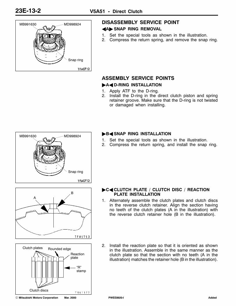
DISASSEMBLY SERVICE POINTAA"SNAP RING REMOVAL1. Set the special tools as shown in the illustration.2. Compress the return spring, and remove the snap ring.
ASSEMBLY SERVICE POINTS"AAD-RING INSTALLATION1. Apply ATF to the D-ring.2. Install the D-ring in the direct clutch piston and spring
retainer groove. Make sure that the D-ring is not twistedor damaged when installing.
"BASNAP RING INSTALLATION1. Set the special tools as shown in the illustration.2. Compress the return spring, and install the snap ring.
"CACLUTCH PLATE / CLUTCH DISC / REACTIONPLATE INSTALLATION
1. Alternately assemble the clutch plates and clutch discsin the reverse clutch retainer. Align the section havingno teeth of the clutch plates (A in the illustration) withthe reverse clutch retainer hole (B in the illustration).
2. Install the reaction plate so that it is oriented as shownin the illustration. Assemble in the same manner as theclutch plate so that the section with no teeth (A in theillustration) matches the retainer hole (B in the illustration).
AddedPWEE8920-IE Mar. 2000Mitsubishi Motors Corporation
Snap ring
MB991630 MD998924
Snap ring
MB991630 MD998924
AB
Clutch plates
Clutch discs
Rounded edge
�R�stamp
Reactionplate

V5A51 - Direct Clutch 23E-13-3
"DASNAP RING INSTALLATION1. Install the snap ring in the direct clutch retainer groove.
2. Press the entire periphery of the reaction plate with aforce of 49 N, and confirm that the clearance betweenthe snap ring and reaction plate (direct clutch end play)is the standard value. If the clearance is not at the standardvalue, select a suitable snap ring and adjust so that theclearance is within the standard value.
Standard value: 1.0 - 1.2 mm
AddedPWEE8920-IE Mar. 2000Mitsubishi Motors Corporation
Snap ring
Snap ring
Standard value
Reactionplate

V5A51 - Output Shaft Support 23E-14-1
14. OUTPUT SHAFT SUPPORTDISASSEMBLY AND ASSEMBLY
1
2
4
Apply automatictransmission fluid toall moving partsbefore installation.
3
Disassembly steps1. Snap ring
"AA 2. One-way clutch3. Seal ring4. Output shaft support
ASSEMBLY SERVICE POINT"AAONE-WAY CLUTCH INSTALLATIONInstall the one-way clutch in such a way that it will be orientedin the direction shown.
AddedPWEE8920-IE Mar. 2000Mitsubishi Motors Corporation
Output shaftsupport
Identificationgroove
One-wayclutch
V5A51 - Transfer 23E-15-1
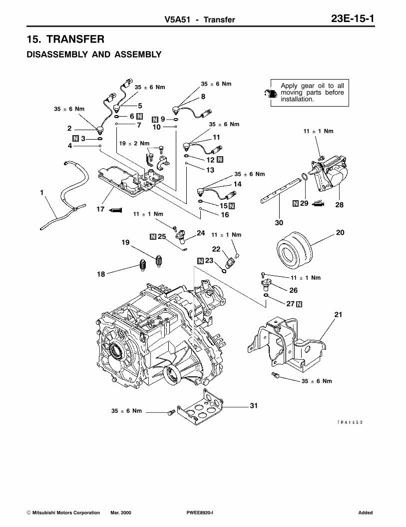
15. TRANSFERDISASSEMBLY AND ASSEMBLY
1
23
4
56
8
9
11
1213
14
35 ± 6 Nm
7 10
1516
17
18
1920
21
22
23
2425
26
27
2829
30
3135 ± 6 Nm
35 ± 6 Nm
11 ± 1 Nm
11 ± 1 Nm
11 ± 1 Nm
35 ± 6 Nm 35 ± 6 Nm
35 ± 6 Nm
35 ± 6 Nm
19 ± 2 Nm
11 ± 1 Nm
Apply gear oil to allmoving parts beforeinstallation.
AddedPWEE8920-IE Mar. 2000Mitsubishi Motors Corporation

V5A51 - Transfer23E-15-2
Disassembly steps1. Vacuum hose
"WA 2. 4LLC switch3. Gasket4. Steel ball
"WA 5. 2WD switch6. Gasket7. Steel ball
"WA 8. Center differential lock switch9. Gasket10. Steel ball
"WA 11. 4H switch12. Gasket13. Steel ball
"WA14. 2WD-4WD switch15. Gasket16. Steel ball
"VA 17. Transfer case cover"UA 18. Shift rail drive gear"UA 19. Shift rail drive gear
20. Dust seal guard21. Dynamic damper22. Vehicle speed sensor23. O-ring24. Rear output sensor25. O-ring26. Front output sensor27. O-ring
"TA 28. Shift actuator29. O-ring
"TA 30. Main shift rail31. Under guard (EXP)
AddedPWEE8920-IE Mar. 2000Mitsubishi Motors Corporation

V5A51 - Transfer 23E-15-3
51
49
50
35
52
5453
56
36
55
33
34
Apply gear oil to allmoving parts beforeinstallation.
35 ± 6 Nm37
3840
3941
4243
44
45
4647
48
57
58
59
6163
60
64
62
6566
35 ± 6 Nm
32
Disassembly steps"SA 32. Rear cover"RA 33. Oil seal
34. Snap ring35. Sensor rotor36. Steel ball37. Oil guide
"QA 38. Spacer39. Snap ring
"PA 40. Snap ring"OA 41. Chain cover"NA 42. Rear output shaft
43. O-ring44. Bearing45. Snap ring46. Center differential planetary carrier47. Viscous coupling
AA" "MA 48. ChainAA" "MA 49. Front output shaft
"MA 50. Drive sprocket51. Bearing
"LA 52. Synchronizer inner ring"LA 53. Synchronizer cone"LA 54. Synchronizer outer ring
55. Synchronizer spring"KA 56. Snap ring
57. 2-4WD clutch hubAA" 58. Sun gear
59. Bearing60. Wave spring
"JA 61. 2-4WD clutch sleeve"JA 62. 2-4WD shift fork"IA 63. Spacer"IA 64. Steel ball"HA 65. Snap ring
66. Differential lock hub
AddedPWEE8920-IE Mar. 2000Mitsubishi Motors Corporation

V5A51 - Transfer23E-15-4
67
Apply gear oil to allmoving parts beforeinstallation.
20 ± 2 Nm
68
71
7374
72
7675
69
70
7980
81
82
77
7883
35 ± 6 Nm
35 ± 6 Nm
Disassembly steps"GA 67. Transfer case plate
68. Bearing69. Counter shaft gear
"FA 70. Spacer"EA 71. H-L clutch sleeve"EA 72. H-L shift fork"DA 73. Snap ring
74. H-L clutch hub75. Low speed gear
76. Bearing"CA 77. Rear bearing retainer
78. Transfer drive shaft79. Dust seal guard
"BA 80. Oil sealAB" "AA 81. Oil pool cover
82. Oil guide83. Transfer case
AddedPWEE8920-IE Mar. 2000Mitsubishi Motors Corporation

V5A51 - Transfer 23E-15-5
DISASSEMBLY SERVICE POINTSAA"CHAIN / FRONT OUTPUT SHAFT / SUN GEAR
REMOVALRemove the chain, front output shaft and sun gear as a setfrom the transfer case.
AB"OIL POOL COVER REMOVALUnstake the positions shown in the illustration to removethe oil pool cover.
CautionD The oil pool cover normally does not require
disassembly. Once it is removed, the transfer casecannot be reused.
ASSEMBLY SERVICE POINTS"AAOIL POOL COVER INSTALLATIONInstall the oil pool cover on a new transfer case. Stake theprojecting portions of the transfer so that the dimensionswill be as illustrated.
"BAOIL SEAL INSTALLATION1. Use the special tools to install the oil seal on the transfer
case.2. Apply grease to the lip of the oil seal.
Specified grease:MITSUBISHI genuine grease part No. 0101011 orequivalent
"CAREAR BEARING RETAINER INSTALLATIONThe bolts used for mounting the rear bearing retainer arepre-coated ones.When they are to be reused, apply sealant to the threadedportion before installation.
Specified sealant:MITSUBISHI genuine sealant part No. MD997740 orequivalent
AddedPWEE8920-IE Mar. 2000Mitsubishi Motors Corporation
5 mm
2 mm
MB990932MB990938

V5A51 - Transfer23E-15-6
"DASNAP RING INSTALLATIONSelect a proper snap ring so that the end play of the H-Lclutch hub will have the standard value, and install the snapring on the transfer drive shaft.
Standard value: 0 - 0.08 mm
"EA H-L SHIFT FORK / H-L CLUTCH SLEEVEINSTALLATION
Apply grease to the H-L shift fork shaft inserting portion, andinstall the H-L shift fork and H-L clutch sleeve in combinedstate in the transfer case.
Specified grease:MITSUBISHI genuine grease part No. 0101011 orequivalent
"FA SPACER INSTALLATION1. Put pieces of solder (approx. 10 mm long and 1.6 mm
in diameter) at the illustrated positions of the transfercase.
2. Install the countershaft gear and transfer case plate andtighten the bolts to the specified torque.
3. If the pieces of solder are not crushed, put thicker piecesof solder and perform Steps 1 and 2.
4. Measure the thickness of the crushed pieces of solderwith a micrometer, and select a spacer of proper thicknessso that the end play will have the standard value.
Standard value: 0 - 0.15 mm
"GATRANSFER CASE PLATE INSTALLATION1. Apply grease to the illustrated position of the high/low
shift rail inserting portion of the transfer case plate.
Specified grease:MITSUBISHI genuine grease part No. 0101011 orequivalent
AddedPWEE8920-IE Mar. 2000Mitsubishi Motors Corporation
Solder

V5A51 - Transfer 23E-15-7
2. Face the notched portion of the input gear in the illustrateddirection (in the direction of the countershaft gear bearinghole).
3. Apply sealant to the illustrated position of the transfercase.
Specified sealant:MITSUBISHI genuine sealant part No. MD997740or equivalent
CautionD Squeeze sealant out evenly to make sure that it
is not broken or excessively supplied.
4. While making sure that the notched portion of the inputgear positioned in Step 2 is in alignment with the gearportion of the countershaft, install the transfer case plate.
CautionD If the sub gear does not readily come in mesh
with the countershaft gear, rotate the transfer driveshaft, etc. to securely engage it.
"HASNAP RING INSTALLATIONSelect a proper snap ring so that the end play of the differentiallock hub will have the standard value, and install it on thetransfer drive shaft.
Standard value: 0 - 0.08 mm
"IA STEEL BALL / SPACER INSTALLATIONInstall the steel ball in the illustrated position of the transferdrive shaft and install the spacer with its oil groove towardthe chain cover.
AddedPWEE8920-IE Mar. 2000Mitsubishi Motors Corporation
Steel ball

V5A51 - Transfer23E-15-8
"JA 2-4WD SHIFT FORK / 2-4WD CLUTCH SLEEVEINSTALLATION
Apply grease to the 2-4WD shift fork shaft inserting portionand install the 2-4WD shift fork and 2-4WD clutch sleevein combined state in the transfer case.
Specified grease:MITSUBISHI genuine grease part No. 0101011 orequivalent
"KASNAP RING INSTALLATIONSelect a proper snap ring so that the end play of the 2-4WDclutch hub will have the standard value, and install it on thesun gear.
Standard value: 0 - 0.08 mm
"LA SYNCHRONIZER OUTER RING / SYNCHRONIZERCONE / SYNCHRONIZER INNER RINGINSTALLATION
1. Combine the synchronizer outer ring, synchronizer coneand synchronizer inner ring, press them against the drivesprocket, and measure the dimension shown in theillustration.
Limit: 0.3 mm
2. If the dimension is out of the limit value, replace themwith a synchronizer ring set.
3. Apply gear oil to the synchronizer outer ring andsynchronizer inner ring.
4. Line up the notched portion of the 2-4WD clutch hubwith the projecting portion of the synchronizer ring andinstall the ring on the 2-4WD clutch hub.
"MADRIVE SPROCKET / FRONT OUTPUT SHAFT /CHAIN INSTALLATION
1. Set the chain in mesh with the drive sprocket and frontoutput shaft sprocket and install them in the transfer case.
AddedPWEE8920-IE Mar. 2000Mitsubishi Motors Corporation

V5A51 - Transfer 23E-15-9
2. Install the drive sprocket so that its illustrated holes willmatch the projecting portions of the synchronizer cone.
"NAREAR OUTPUT SHAFT INSTALLATIONApply grease to the O-ring at the illustrated position and installthe rear output shaft.
Specified grease:MITSUBISHI genuine grease part No. 0101011 orequivalent
"OACHAIN COVER INSTALLATION1. Apply grease to the indicated 2-4WD shift rail inserting
portion.
Specified grease:MITSUBISHI genuine grease part No. 0101011 orequivalent
2. Apply a bead of sealant to the illustrated position of thechain cover.
Specified sealant:MITSUBISHI genuine sealant part No. MD997740or equivalent
CautionD Squeeze the sealant out evenly to make sure that
it is not broken or excessively supplied.
"PA SNAP RING ISNTALLATION1. Install the snap ring in the bearing groove of the rear
output shaft.2. With the rear output shaft pressed against the chain cover,
measure the clearance between the chain cover and snapring.
3. Select a snap ring whose thickness is the dimension ofthe measured clearance plus the standard value.
Standard value: 0.12 - 0.24 mm
AddedPWEE8920-IE Mar. 2000Mitsubishi Motors Corporation

V5A51 - Transfer23E-15-10
4. Remove the snap ring from the bearing groove of therear output shaft, install the selected snap ring, andreinstall the removed snap ring in the bearing grooveof the rear output shaft.
"QASPACER INSTALLATION1. With the rear output shaft pressed toward the chain cover,
measure the projection of the bearing from the chaincover.
CautionD Measure the projection with the snap ring
installed.
2. Measure the dimension of the rear cover concave portionat the illustrated position.
3. Subtract the measured value in Step 1 from the measuredvalue in Step 2 to calculate the clearance between thebearing and rear cover. Select a proper spacer so thatthe clearance will have the standard value.
Standard value: 0 - 0.12 mm
"RAOIL SEAL INSTALLATION1. Use the special tools to install the oil seal in the rear
cover.2. Apply grease to the lip of the oil seal.
Specified grease:MITSUBISHI genuine grease part No. 0101011 orequivalent
"SA REAR COVER INSTALLATIONApply sealant to the illustrated position of the chain cover.
Specified sealant:MITSUBISHI genuine sealant part No. MD997740 orequivalent
CautionD Squeeze the sealant out evenly to make sure that
it is not broken or excessively supplied.
AddedPWEE8920-IE Mar. 2000Mitsubishi Motors Corporation
Projection
Concaveportion
MB990938
MB990932

V5A51 - Transfer 23E-15-11
"TA MAIN SHIFT RAIL / SHIFT ACTUATORINSTALLATION
1. Apply grease to the O-ring.
Specified grease:MITSUBISHI genuine grease part No. 0101011 orequivalent
2. Combine the main shift rail key with actuator key andinsert them in the transfer case.
"UASHIFT RAIL DRIVE GEAR INSTALLATIONInstall the shift rail drive gear with its marked tooth in meshwith the third gear groove of each shift rail.
"VA TRANSFER CASE COVER INSTALLATIONApply sealant to the illustrated position of the transfer casecover.
Specified sealant:MITSUBISHI genuine sealant part No. MD997740 orequivalent
CautionD Squeeze the sealant out evenly to make sure that
it is not broken or excessively supplied.
"WA SWITCH INSTALLATIONInstall the switches in the right positions.
Switch name Tube color Connector color
A 4LLC switch Black Brown
B 2WD switch Black Black
C Center differentiallock switch
Blue Brown
D 4H switch Blue White
E 2-4WD switch Blue Black
INSPECTIONSWITCHESCheck for the continuity between the connector terminal andswitch body. Replace the switch if found faulty.
Switch state Continuity
Switch end pressed No
Switch end released Yes
AddedPWEE8920-IE Mar. 2000Mitsubishi Motors Corporation
Third gear
Mark
EA D B
C

V5A51 - Transfer Case Plate 23E-16-1
16. TRANSFER CASE PLATEDISASSEMBLY AND ASSEMBLY
20 ± 2 Nm
1
2
3
45
6
Apply gear oil to allmoving parts beforeinstallation.
Disassembly steps"BA 1. Bolt
2. Bearing retainer3. Transfer input gear
"AA 4. Oil seal5. Baffle plate6. Transfer case plate
ASSEMBLY SERVICE POINTS"AAOIL SEAL INSTALLATION1. Use the special tool to install the oil seal.2. Apply grease to the lip of the oil seal.
Specified grease:MITSUBISHI genuine grease part No. 0101011 orequivalent
AddedPWEE8920-IE Mar. 2000Mitsubishi Motors Corporation
MB990938
MB990936

V5A51 - Transfer Case Plate23E-16-2
"BABOLT INSTALLATIONApply sealant to the threads.
Specified sealant:MITSUBISHI genuine sealant part No. MD997740 orequivalent
NOTENew bolts are precoated with sealant, so sealant does notneed to be applied.
AddedPWEE8920-IE Mar. 2000Mitsubishi Motors Corporation

V5A51 - Input Gear 23E-17-1
17. INPUT GEARDISASSEMBLY AND ASSEMBLY
1
2
34
5
6
Apply gear oil to allmoving parts beforeinstallation.
Disassembly steps"BA 1. Snap ring
AA" "AA 2. Ball bearing3. Snap ring (some model)4. Cone spring (some model)5. Sub gear (some model)6. Transfer input gear
DISASSEMBLY SERVICE POINTAA"BALL BEARING REMOVALUse the special tool to remove the ball bearing.
ASSEMBLY SERVICE POINTS"AABALL BEARING INSTALLATIONUse the special tools to install the ball bearing.
AddedPWEE8920-IE Mar. 2000Mitsubishi Motors Corporation
MD998801
MD998812
MD998826

V5A51 - Input Gear23E-17-2
"BASNAP RING INSTALLATION1. Install the thickest snap ring that can be fitted in the
snap ring groove of the input gear.2. Make sure that the ball bearing end play meets the
standard value.
Standard value: 0 - 0.06 mm
AddedPWEE8920-IE Mar. 2000Mitsubishi Motors Corporation

V5A51 - Countershaft Gear 23E-18-1
18. COUNTERSHAFT GEARDISASSEMBLY AND ASSEMBLY
1
2
3
4
5
6
Apply gear oil to allmoving parts beforeinstallation.
Disassembly stepsAA" "CA 1. Ball bearing
"BA 2. Snap ringAB" "AA 3. Spacer
AB" "AA 4. Roller bearingAB" "AA 5. Inner race
6. Countershaft gear
DISASSEMBLY SERVICE POINTSAA"BALL BEARING REMOVALUse the special tool to remove the ball bearing.
AB"SPACER / ROLLER BEARING / INNER RACEREMOVAL
1. Remove the spacer and roller bearing.2. Using the special tool, remove the inner race.
NOTEThe removal sequence of roller bearing parts varydepending on the direction that the roller bearing wasinstalled. In some cases, the inner race, roller bearingand spacer may have to be simultaneously removed.
AddedPWEE8920-IE Mar. 2000Mitsubishi Motors Corporation
MD998801
MD998368MD998801
V5A51 - Countershaft Gear23E-18-2
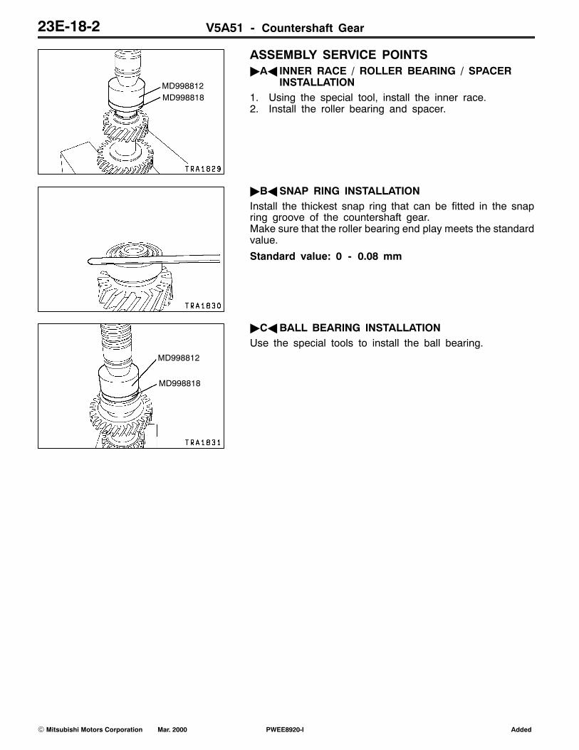
ASSEMBLY SERVICE POINTS"AA INNER RACE / ROLLER BEARING / SPACER
INSTALLATION1. Using the special tool, install the inner race.2. Install the roller bearing and spacer.
"BASNAP RING INSTALLATIONInstall the thickest snap ring that can be fitted in the snapring groove of the countershaft gear.Make sure that the roller bearing end play meets the standardvalue.
Standard value: 0 - 0.08 mm
"CABALL BEARING INSTALLATIONUse the special tools to install the ball bearing.
AddedPWEE8920-IE Mar. 2000Mitsubishi Motors Corporation
MD998812MD998818
MD998812
MD998818

V5A51 - Rear Output Shaft 23E-19-1
19. REAR OUTPUT SHAFTDISASSEMBLY AND ASSEMBLY
1
2
5
4
3
Apply gear oil to allmoving parts beforeinstallation.
Disassembly steps"CA 1. Snap ring
2. Annulus gear"BA 3. Snap ring
AA" "AA 4. Ball bearing5. Rear output shaft
DISASSEMBLY SERVICE POINTAA"BALL BEARING REMOVALUse the special tool to remove the ball bearing.
ASSEMBLY SERVICE POINTS"AABALL BEARING INSTALLATIONUse the special tools to install the ball bearing.
AddedPWEE8920-IE Mar. 2000Mitsubishi Motors Corporation
MD998917
MD998812
MD998814
MD998824
V5A51 - Rear Output Shaft23E-19-2
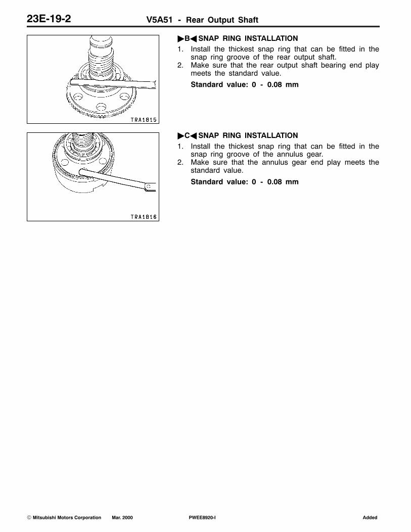
"BASNAP RING INSTALLATION1. Install the thickest snap ring that can be fitted in the
snap ring groove of the rear output shaft.2. Make sure that the rear output shaft bearing end play
meets the standard value.
Standard value: 0 - 0.08 mm
"CASNAP RING INSTALLATION1. Install the thickest snap ring that can be fitted in the
snap ring groove of the annulus gear.2. Make sure that the annulus gear end play meets the
standard value.
Standard value: 0 - 0.08 mm
AddedPWEE8920-IE Mar. 2000Mitsubishi Motors Corporation

V5A51 - Front Output Shaft 23E-20-1
20. FRONT OUTPUT SHAFTDISASSEMBLY AND ASSEMBLY
12
3
4
Apply gear oil to allmoving parts beforeinstallation.
Disassembly stepsAA" "BA 1. Ball bearing
2. Sensor rotorAB" "AA 3. Ball bearing
4. Front output shaft
DISASSEMBLY SERVICE POINTAA"BALL BEARING REMOVAL1. Use the special tool to support the ball bearing.2. Press the front output shaft with a press and remove
the ball bearings.
AB"BALL BEARING REMOVAL1. Use the special tool to support the ball bearing.2. Press the front output shaft with a press and remove
the ball bearings.
AddedPWEE8920-IE Mar. 2000Mitsubishi Motors Corporation
MD998801
MD998801

V5A51 - Front Output Shaft23E-20-2
ASSEMBLY SERVICE POINTS"AABALL BEARING INSTALLATION1. Use the special tool to support the front output shaft.2. Use the special tools to install the ball bearing.
"BABALL BEARING INSTALLATION1. Use the special tool to support the front output shaft.2. Use the special tools to install the ball bearing.
AddedPWEE8920-IE Mar. 2000Mitsubishi Motors Corporation
MD998812
MD998818
MD998813
MD998812
MD998818

V5A51 - Transfer Drive Shaft 23E-21-1
21. TRANSFER DRIVE SHAFTDISASSEMBLY AND ASSEMBLY
1
2
Apply gear oil to allmoving parts beforeinstallation.
Disassembly stepsAA" "AA 1. Ball bearing
2. Transfer drive shaft
DISASSEMBLY SERVICE POINTAA"BALL BEARING REMOVALUse the special tool to remove the ball bearing.
ASSEMBLY SERVICE POINT"AABALL BEARING INSTALLATIONUse the special tools to install the ball bearing.
AddedPWEE8920-IE Mar. 2000Mitsubishi Motors Corporation
MD998917
MD998812
MD998814
MD998830
MD998192
V5A51 - Shift Rail Drive Gear 23E-22-1
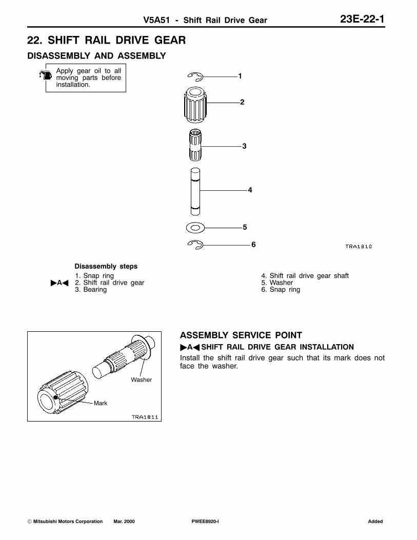
22. SHIFT RAIL DRIVE GEARDISASSEMBLY AND ASSEMBLY
1
2
3
4
5
6
Apply gear oil to allmoving parts beforeinstallation.
Disassembly steps1. Snap ring
"AA 2. Shift rail drive gear3. Bearing
4. Shift rail drive gear shaft5. Washer6. Snap ring
ASSEMBLY SERVICE POINT"AASHIFT RAIL DRIVE GEAR INSTALLATIONInstall the shift rail drive gear such that its mark does notface the washer.
AddedPWEE8920-IE Mar. 2000Mitsubishi Motors Corporation
Washer
Mark

V5A51 - 2-4WD Shift Rail and H-L Shift Rail 23E-23-1
23. 2-4WD SHIFT RAIL AND H-L SHIFT RAILDISASSEMBLY AND ASSEMBLY
2
3
46
7
Apply gear oil to allmoving parts beforeinstallation. 1
5
Disassembly steps"BA 1. Spring pin"AA 2. 2-4WD shift fork
3. Spring
"AA 4. 2-4WD shift rail"BA 5. Spring pin"AA 6. H-L shift fork"AA 7. H-L shift rail
ASSEMBLY SERVICE POINTS"AASHIFT FORK / SHIFT RAIL INSTALLATIONApply grease to the outer periphery of the shift fork mountingportion of the shift rail and then assemble the shift fork andshift rail.
Specified grease:Mitsubishi genuine grease part No. 0101011 orequivalent
"BASPRING PIN INSTALLATIONInstall the spring pin with its split toward the forward endof the transfer.
AddedPWEE8920-IE Mar. 2000Mitsubishi Motors Corporation
H-L shift rail 2-4WD shift rail

NOTES