Embed Size (px)
Citation preview

K-1
E6581386
11
11. Table of parameters
1. User parameter *3 Sensorless vector/PG feedback control (:Effective, -:Ineffective)
Title Communi
cation No.
Function Adjustment range
Minimum setting unit
(Panel/Communication)
Default setting
Write during running
Vector control
PM control
*2
V/f
*1 Reference
- Operation frequency of operation panel
~ Hz 0.1/0.01 0.0 Enabled / 3. 2
*1: V/f : Any setting of = , , *2: PM control : = setting *3: Sensorless vector : Any setting of = , , , / PG feedback control : =
2. Basic parameter [1/4] Sensorless vector/PG feedback control (:Effective, -:Ineffective)
Title Communi
cation No.
Function Adjustment range
Minimum setting unit
(Panel/Communication)
Default setting
Write during running
Vector control
PM control
V/f Reference
- History function 1/1 - - / 5. 1
0000 Automatic acceleration/deceleration0:Disabled 1:Automatic setting 2:Automatic setting (during acceleration only)
1/1 0 Disabled / 5. 2
0001 Automatic torque boost 0:Disabled 1:Automatic torque boost + auto-tuning 1 2:Sensorless vector control + auto-tuning 1
1/1 0 Disabled / 5. 3
0040 Automatic function setting
0:Disabled 1:Frequency setting by means of voltage 2:Frequency setting by means of current 3:Voltage/current switching from external terminal 4:Frequency setting on operation panel and operation by
means of terminals 5:Frequency setting and operation on operation panel 6:Coast stop
1/1 0 Disabled / 5. 4
0003 Command mode selection
0:Terminal input enabled 1:Operation panel input enabled (including LED/LCD
option input) 2:2-wire RS485 communication input 3:4-wireRS485 communication input 4:Communication option input
1/1 0 Disabled / 5. 5
0004 Frequency setting mode selection 1
1:VI/II (voltage/current input) 2:RR/S4 (potentiometer/voltage input) 3:RX (voltage input) 4:Operation panel input enabled (including LED/LCD
option input) 5:2-wire RS485 communication input 6:4-wire RS485 communication input 7:Communication option input 8:Optional AI1 (differential current input) 9:Optional AI2 (voltage/current input) 10:External contact Up/Down 11:Optional RP pulse input 12:Optional high-speed pulse input
1/1 2 Disabled / 5. 5

K-2
E6581386
11
2. Basic parameter [2/4] Sensorless vector/PG feedback control (:Effective, -:Ineffective)
Title Communi
cation No.
Function Adjustment range
Minimum setting unit
(Panel/Communication)
Default setting
Write during running
Vector control
PM control
V/f Reference
0015 V/f control mode selection
0:Constant torque characteristics 1:Voltage decrease curve 2:Automatic torque boost 3:Sensorless vector control 1 (speed) 4:- 5:V/f 5-point setting 6:PM control 7:PG feedback control 8:- 9:Energy-saving 10:Advanced energy-saving
1/1 0 Disabled
-/- -/- /- /- -
-/- -/- -/ - /- /-
- - - - - - - - - -
- - - - - - - -
5. 6
0016 Manual torque boost 1 0.0~30.0% 0.1/0.1 *1 Enabled - 5. 7
0014 Base frequency 1 25.0~500.0Hz 0.1/0.01 *3 Disabled / 5. 8
0409 Base frequency voltage 1 200V class:50~330V 400V class:50~660V
1/0.1 *1 Disabled / 5. 8
0011 Maximum frequency 30.0~500.0Hz 0.1/0.01 80.0 Disabled / 5. 9
0012 Upper limit frequency 0.0~ Hz 0.1/0.01 *3 Enabled / 5. 10
0013 Lower limit frequency 0.0~ Hz 0.1/0.01 0.0 Enabled / 5. 10
0009 Acceleration time 1 0.1~6000 sec. 0.1/0.1 *2 *1 Enabled / 5. 2
0010 Deceleration time 1 0.1~6000 sec. 0.1/0.1 *2 *1 Enabled / 5. 2
0213 RR/S4 input point 2 frequency 0.0~ Hz 0.1/0.01 *3 Enabled / 5. 11
0204 VI/II input point 2 frequency 0.0~ Hz 0.1/0.01 *3 Enabled / 5. 11
0018 Preset speed operation frequency 1 ~ Hz 0.1/0.01 0.0 Enabled / 5. 12
0019 Preset speed operation frequency 2 ~ Hz 0.1/0.01 0.0 Enabled / 5. 12
0020 Preset speed operation frequency 3 ~ Hz 0.1/0.01 0.0 Enabled / 5. 12
0021 Preset speed operation frequency 4 ~ Hz 0.1/0.01 0.0 Enabled / 5. 12
0022 Preset speed operation frequency 5 ~ Hz 0.1/0.01 0.0 Enabled / 5. 12
0023 Preset speed operation frequency 6 ~ Hz 0.1/0.01 0.0 Enabled / 5. 12
0024 Preset speed operation frequency 7 ~ Hz 0.1/0.01 0.0 Enabled / 5. 12
0008 Forward run/reverse run selection (operation panel operation)
0:Forward run 1:Reverse run 2:Forward run (Forward/reverse switchable on operation
panel) 3:Reverse run (Forward/reverse switchable on
operation panel)
1/1 0 Enabled / 5. 13
0600 Motor electronic thermal protection level 1
10~100% 1/1 100 Enabled / 5. 14
*1: Default values vary depending on the capacity. ⇒ See the table of K-42. *2: Changing the parameter enables to set to 0.01 sec. (adjustment range: 0.01~600.0 sec.). *3: Inverter with a model number ending with -WN: 60.0 -WP: 50.0

K-3
E6581386
11
2. Basic parameter [3/4] Sensorless vector/PG feedback control (:Effective, -:Ineffective)
Title Communi
cation No.
Function Adjustment range
Minimum setting unit
(Panel/Communication)
Default setting
Write during running
Vector control
PM control
V/f Reference
Setting Motor typeOverload protection
OL stall
0 (protect) × (not stall)
1 (protect) (stall)
2 × (not protect) × (not stall)
3
Standard Motor
× (not protect) (stall)
4 (protect) × (not stall)
5 (protect) (stall)
6 × (not protect) × (not stall)
0017 Electronic thermal protection characteristic selection
7
VF Motor
× (not protect) (stall)
1/1 0 Enabled / 5. 14
0701 Current/voltage unit selection 0:% 1:A (ampere)/V (volt)
1/1 0 Enabled / 5. 15
0005 FM terminal meter selection 0~76 *1 1/1 0 Enabled / 5. 16
0006 FM terminal meter adjustment - 1/1 *4 Enabled / 5. 16
0670 AM terminal meter selection 0~76 *1 1/1 2 Enabled / 5. 16
0671 AM terminal meter adjustment - 1/1 *4 Enabled / 5. 16
0300 PWM carrier frequency 1.0~16.0kHz (2.5~8.0kHz) *2 0.1/0.1 *3 Enabled / 5. 17
0301 Auto-restart control selection
0:Disabled 1:At auto-restart after momentary stop 2:When turning ST on or off 3:1+2 4:At start-up
1/1 0 Disabled / 5. 18.1
0302 Regenerative power ride-through control
0:Disabled 1:Power ride-through 2:Deceleration stop during power failure
1/1 0 Disabled / 5. 18. 2
Setting Braking function ST-off overload
detect
0 Disabled - ―
1 protect
2 Enabled
not protect
3 protect
4
Enabled (It is effective
in trip condition.)
*5) Disabled
not protect
5 protect
6 Enabled
not protect
7 protect
0304 Dynamic braking selection
8
Enabled (It isn't
effective in trip.condition ) Disabled
not protect
1/1 0 Disabled / 5. 19
*1: ⇒ For the adjustment range, see the table on page K-35. *2: For 200V-55kW to 200V-90kW models and 400V-90kW to 400V-630kW models, the carrier frequency is between 2.5 and 8.0kHz inclusive. *3: Default values vary depending on the capacity. ⇒ See the table of K-42. *4: Default setting value is adjusted for connection of frequency meters "QS60T". (Between FM and CCA: Approx. 3.6V) (Between AM and CCA: Approx. 3.6V) *5: The state of olr trip is excluded.

K-4
E6581386
11
2. Basic parameter [4/4] Sensorless vector/PG feedback control (:Effective, -:Ineffective)
Title Communi
cation No.
Function Adjustment range
Minimum setting unit
(Panel/Communication)
Default setting
Write during running
Vector control
PM control
V/f Reference
0308 Dynamic braking resistance 0.5~1000Ω 0.1/0.1 *2 Disabled / 5. 19
0309 Dynamic braking resistor capacity 0.01~600.0kW 0.01/0.01 *2 Disabled / 5. 19
0007 Factory default setting
0: - 1:50 Hz default setting 2:60 Hz default setting 3:Factory default setting 4:Trip clear 5:Cumulative operation time cleared 6:Initialization of type information 7:Save user-defined parameters 8:Reset of user-defined parameters 9:Cumulative fan operation time record clear 10:Acceleration/deceleration time setting 0.01
sec.~600.0 sec. *1 11:Acceleration/deceleration time setting 0.1
sec.~6000sec.
1/1 0 Disabled / 5. 20
0050 Registered parameter display selection
0:Standard setting mode at turn on the power 1:Quick mode at turn on the power 2:Quick mode only
1/1 0 Enabled / 5. 22
~ - Extended parameters Set detailed parameters shown in the following pages. - - - / -
- Automatic edit function - - - / 4. 2
*1: If is set to , the optional communication devices DEV002Z, PDP002Z, MTS001Z, APG001Z, LIU006Z, BCN001Z, IPE001Z and CCL001Z cannot be used with the inverter. (The
personal computer communications software PCM001Z cannot be used, either.) Furthermore, the copy function of the LED extended panel option (RKP002Z) does not work normally, so use
only the parameter setting function and the monitoring function.
*2: Default values vary depending on the capacity. ⇒ See the table of K-42.

K-5
E6581386
11
3. Extended parameters [1] Frequency signal Sensorless vector/PG feedback control (:Effective, -:Ineffective)
Title Communi
cation No.
Function Adjustment range
Minimum setting unit
(Panel/Communication)
Default setting
Write during running
Vector control
PM control
V/f Reference
0100 Low-speed signal output frequency 0.0~ Hz 0.1/0.01 0.0 Enabled / 6. 1. 1
0101 Speed reach setting frequency 0.0~ Hz 0.1/0.01 0.0 Enabled / 6. 1. 2
0102 Speed reach detection band 0.0~ Hz 0.1/0.01 2.5 Enabled / 6. 1. 2
[2] Input signal selection Sensorless vector/PG feedback control (:Effective, -:Ineffective)
Title Communi
cation No.
Function Adjustment range
Minimum setting unit
(Panel/Communication)
Default setting
Write during running
Vector control
PM control
V/f Reference
0105 Priority when forward/reverse run commands are entered simultaneously
0:Reverse run 1:Stop
1/1 1 Disabled / 6. 2. 1
0106 Input terminal priority selection 0:Disabled 1:Enabled
1/1 0 Disabled / 6. 2. 2
0108 Analog VI/II voltage/current switching 0:Voltage input 1:Current input
1/1 0 Disabled / 6. 2. 3
0109 Analog AI2 (optional circuit board) voltage/current switching
0:Voltage input 1:Current input
1/1 0 Disabled / 6. 2. 3

K-6
E6581386
11
[3] Terminal function selection Sensorless vector/PG feedback control (:Effective, -:Ineffective)
Title Communi
cation No.
Function Adjustment range
Minimum setting unit
(Panel/Communication)
Default setting
Write during running
Vector control
PM control
V/f Reference
0110 Always ON function selection 1 0~135 *1 1/1 6 Disabled / 6. 3. 1
0111 Input terminal function selection 1 (F) 0~135 *1 1/1 2 Disabled / 7. 2. 1
0112 Input terminal function selection 2 (R) 0~135 *1 1/1 4 Disabled / 7. 2. 1
0114 Input terminal function selection 4 (RES) 0~135 *1 1/1 8 Disabled / 7. 2. 1
0115 Input terminal function selection 5 (S1) 0~135 *1 1/1 10 Disabled / 7. 2. 1
0116 Input terminal function selection 6 (S2) 0~135 *1 1/1 12 Disabled / 7. 2. 1
0117 Input terminal function selection 7 (S3) 0~135 *1 1/1 14 Disabled / 7. 2. 1
0118 Input terminal function selection 8 (RR/S4) 0~135 *1 1/1 16 Disabled / 7. 2. 1
0119 Input terminal function selection 9 (LI1) 0~135 *1 1/1 0 Disabled / 7. 2. 1
0120 Input terminal function selection 10 (LI2) 0~135 *1 1/1 0 Disabled / 7. 2. 1
0121 Input terminal selection 11 (LI3) 0~135 *1 1/1 0 Disabled / 7. 2. 1
0122 Input terminal selection 12 (LI4) 0~135 *1 1/1 0 Disabled / 7. 2. 1
0123 Input terminal selection 13 (LI5) 0~135 *1 1/1 0 Disabled / 7. 2. 1
0124 Input terminal selection 14 (LI6) 0~135 *1 1/1 0 Disabled / 7. 2. 1
0125 Input terminal selection 15 (LI7) 0~135 *1 1/1 0 Disabled / 7. 2. 1
0126 Input terminal selection 16 (LI8) 0~135 *1 1/1 0 Disabled / 7. 2. 1
0127 Always ON function selection 2 0~135 *1 1/1 0 Disabled / 6. 3. 1
0128 Always ON function selection 3 0~135 *1 1/1 0 Disabled / 6. 3. 1
0130 Output terminal function selection 1 (OUT1) 0~255 *2 1/1 4 Disabled / 7. 2. 2
0131 Output terminal function selection 2 (OUT2) 0~255 *2 1/1 6 Disabled / 7. 2. 2
0132 Output terminal function selection 3 (FL) 0~255 *2 1/1 10 Disabled / 7. 2. 2
0133 Output terminal function selection 4 (OUT3) 0~255 *2 1/1 254 Disabled / 7. 2. 2
0134 Output terminal function selection 5 (OUT4) 0~255 *2 1/1 254 Disabled / 7. 2. 2
0135 Output terminal function selection 6 (R1) 0~255 *2 1/1 254 Disabled / 7. 2. 2
0136 Output terminal function selection 7 (OUT5) 0~255 *2 1/1 254 Disabled / 7. 2. 2
0137 Output terminal function selection 8 (OUT6) 0~255 *2 1/1 254 Disabled / 7. 2. 2
0138 Output terminal function selection 9 (R2) 0~255 *2 1/1 254 Disabled / 7. 2. 2
*1: ⇒ For the adjustment range, see the table on page K-38. *2: ⇒ For the adjustment range, see the table on page K-39.

K-7
E6581386
11
[4] Terminal response time setup Sensorless vector/PG feedback control (:Effective, -:Ineffective)
Title Communi
cation No.
Function Adjustment range
Minimum setting unit
(Panel/Communication)
Default setting
Write during running
Vector control
PM control
V/f Reference
0168 Output terminal function selection 10 (R3) *1
0~255 *2 1/1 254 Disabled / 7. 2. 2
0169 Output terminal function selection 11 (R4) *1
0~255 *2 1/1 254 Disabled / 7. 2. 2
0170 Base frequency 2 25.0~500.0 Hz 0.1/0.01 *4 Disabled - - 6. 4. 1
0171 Base frequency voltage 2 50~330V/660V 1/0.1 *3 Disabled - - 6. 4. 1
0172 Manual torque boost 2 0.0~30.0% 0.1/0.1 *3 Enabled - - 6. 4. 1
0173 Thermal protection level 2 10~100% 1/1 100 Enabled - - 6. 4. 1
*1: Unsupported option *2: ⇒ For the adjustment range, see the table on page K-39. *3: Default values vary depending on the capacity. ⇒ See the table of K-42. *4: Inverter with a model number ending with -WN: 60.0 -WP: 50.0
[5] V/f 5-point setting Sensorless vector/PG feedback control (:Effective, -:Ineffective)
Title Communi
cation No.
Function Adjustment range
Minimum setting unit
(Panel/Communication)
Default setting
Write during running
Vector control
PM control
V/f Reference
0190 V/f 5-point setting VF1 frequency 0.0~ Hz 0.1/0.01 0.0 Disabled - - 5. 6
0191 V/f 5-point setting VF1 voltage 0.0~100.0% 0.1/0.01 0.0 Disabled - - 5. 6
0192 V/f 5-point setting VF2 frequency 0.0~ Hz 0.1/0.01 0.0 Disabled - - 5. 6
0193 V/f 5-point setting VF2 voltage 0.0~100.0% 0.1/0.01 0.0 Disabled - - 5. 6
0194 V/f 5-point setting VF3 frequency 0.0~ Hz 0.1/0.01 0.0 Disabled - - 5. 6
0195 V/f 5-point setting VF3 voltage 0.0~100.0% 0.1/0.01 0.0 Disabled - - 5. 6
0196 V/f 5-point setting VF4 frequency 0.0~ Hz 0.1/0.01 0.0 Disabled - - 5. 6
0197 V/f 5-point setting VF4 voltage 0.0~100.0% 0.1/0.01 0.0 Disabled - - 5. 6
0198 V/f 5-point setting VF5 frequency 0.0~ Hz 0.1/0.01 0.0 Disabled - - 5. 6
0199 V/f 5-point setting VF5 voltage 0.0~100.0% 0.1/0.01 0.0 Disabled - - 5. 6
[6] Speed/torque reference gain/bias setup [1/3] Sensorless vector/PG feedback control (:Effective, -:Ineffective)
Title Communi
cation No.
Function Adjustment range
Minimum setting unit
(Panel/Communication)
Default setting
Write during running
Vector control
PM control
V/f Reference
0200 Frequency priority selection
0: / terminal switching (input terminal function selection 104, 105)
1: / frequency switching (switching with )
1/1 0 Enabled / 6. 6. 1
0201 VI/II input point 1 setting 0~100% 1/1 0 Enabled / 7. 3. 2
0202 VI/II input point 1 frequency 0.0~ Hz 0.1/0.01 0.0 Enabled / 7. 3. 2

K-8
E6581386
11
[6] Speed/torque reference gain/bias setup [2/3] Sensorless vector/PG feedback control (:Effective, -:Ineffective)
Title Communi
cation No.
Function Adjustment range
Minimum setting unit
(Panel/Communication)
Default setting
Write during running
Vector control
PM control
V/f Reference
0203 VI/II input point 2 setting 0~100% 1/1 100 Enabled / 7. 3. 2
0204 VI/II input point 2 frequency 0.0~ Hz 0.1/0.01 *1 Enabled / 7. 3. 2
0205 VI/II input point 1 rate 0~250% 1/0.01 0 Enabled / - - 7. 3. 2
0206 VI/II input point 2 rate 0~250% 1/0.01 100 Enabled / - - 7. 3. 2
0207 Frequency setting mode selection 2 Same as (1~12) 1/1 1 Disabled / 6. 6. 1
0208 Speed command priority switching frequency
0.1~ Hz 0.1/0.01 0.1 Enabled / 6. 6. 1
0209 Analog input filter
0:No filter 1:Filter approx. 10ms 2:Filter approx. 15ms 3:Filter approx. 30ms 4:Filter approx. 60ms
1/1 0 Enabled / 7. 2. 3
0210 RR/S4 input point 1 setting 0~100% 1/1 0 Enabled / 7. 3. 1
0211 RR/S4 input point 1 frequency 0.0~ Hz 0.1/0.01 0.0 Enabled / 7. 3. 1
0212 RR/S4 input point 2 setting 0~100% 1/1 100 Enabled / 7. 3. 1
0213 RR/S4 input point 2 frequency 0.0~ Hz 0.1/0.01 *1 Enabled / 7. 3. 1
0214 RR/S4 input point 1 rate 0~250% 1/0.01 0 Enabled / - - 7. 3. 1
0215 RR/S4 input point 2 rate 0~250% 1/0.01 100 Enabled / - - 7. 3. 1
0216 RX input point 1 setting -100~100% 1/1 0 Enabled / 7. 3. 3
0217 RX input point 1 frequency 0.0~ Hz 0.1/0.01 0.0 Enabled / 7. 3. 3
0218 RX input point 2 setting -100~100% 1/1 100 Enabled / 7. 3. 3
0219 RX input point 2 frequency 0.0~ Hz 0.1/0.01 *1 Enabled / 7. 3. 3
0220 RX input point 1 rate -250~250% 1/0.01 0 Enabled / - - 7. 3. 3
0221 RX input point 2 rate -250~250% 1/0.01 100 Enabled / - - 7. 3. 3
0222 AI1 input point 1 setting -100~100% 1/1 0 Enabled / *2
0223 AI1 input point 1 frequency 0.0~ Hz 0.1/0.01 0.0 Enabled / *2
0224 AI1 input point 2 setting -100-100% 1/1 100 Enabled / *2
0225 AI1 input point 2 frequency 0.0~ Hz 0.1/0.01 *1 Enabled / *2
0228 AI2 input point 1 setting 0~100% 1/1 0 Enabled / *2
0229 AI2 input point 1 frequency 0.0~ Hz 0.1/0.01 0.0 Enabled / *2
This parameter moves to a fundamental parameter. *1: Inverter with a model number ending with -WN: 60.0 -WP: 50.0 *2: ⇒ For details, refer to Instruction Manual (E6581341) specified in Section 6.36.

K-9
E6581386
11
[6] Speed/torque reference gain/bias setup [3/3] Sensorless vector/PG feedback control (:Effective, -:Ineffective)
Title Communi
cation No.
Function Adjustment range
Minimum setting unit
(Panel/Communication)
Default setting
Write during running
Vector control
PM control
V/f Reference
0230 AI2 input point 2 setting 0~100% 1/1 100 Enabled / *2
0231 AI2 input point 2 frequency 0.0~ Hz 0.1/0.01 *1 Enabled / *2
0234 RP/high speed pulse input point 1 setting 0~100% 1/1 0 Enabled / *3
0235 RP/high speed pulse input point 1 frequency
0.0~ Hz 0.1/0.01 0.0 Enabled / *3
0236 RP/high speed pulse input point 2 setting 0~100% 1/1 100 Enabled / *3
0237 RP/high speed pulse input point 2 frequency
0.0~ Hz 0.1/0.01 *1 Enabled / *3
*1: Inverter with a model number ending with -WN: 60.0 -WP: 50.0 *2: ⇒ For details, refer to Instruction Manual (E6581341) specified in Section 6.36. *3: ⇒ For details, refer to Instruction Manual (E6581319) specified in Section 6.36.
[7] Operation frequency Sensorless vector/PG feedback control (:Effective, -:Ineffective)
Title Communi
cation No.
Function Adjustment range
Minimum setting unit
(Panel/Communication)
Default setting
Write during running
Vector control
PM control
V/f Reference
0240 Starting frequency setting 0.0~10.0Hz 0.1/0.01 0.1 Enabled / 6. 7. 1
0241 Operation start frequency 0.0~ Hz 0.1/0.01 0.0 Enabled / 6. 7. 2
0242 Operation start frequency hysteresis 0.0~30.0Hz 0.1/0.01 0.0 Enabled / 6. 7. 2
0243 Stop frequency setting 0.0~30.0Hz 0.1/0.01 0.0 Enabled / 6. 7. 1
0244 Frequency command dead band 0.0~5.0Hz 0.1/0.01 0.0 Enabled / 6. 7. 3
[8] DC braking Sensorless vector/PG feedback control (:Effective, -:Ineffective)
Title Communi
cation No.
Function Adjustment range
Minimum setting unit
(Panel/Communication)
Default setting
Write during running
Vector control
PM control
V/f Reference
0250 DC braking start frequency 0.0~120.0Hz 0.1/0.01 0.0 Enabled / 6. 8. 1
0251 DC braking current 0~100% 1/1 50 Enabled / 6. 8. 1
0252 DC braking time 0.0~20.0 sec. 0.1/0.1 1.0 Enabled / 6. 8. 1
0253 Forward/reverse DC braking priority control0:Disabled 1:Enabled
1/1 0 Enabled / 6. 8. 1
0254 Motor shaft fixing control 0:Disabled 1:Enabled
1/1 0 Enabled / 6. 8. 2
0255 0Hz command output selection 0:Default (DC braking) 1:0Hz command
1/1 0 Enabled -/ 6. 8. 3
0256 Time limit for lower-limit frequency operation
0.0:Disabled, 0.1~600.0 sec. 0.1/0.1 0.0 Enabled / 6. 9

K-1
0
E6581386
11
[9] Jogging operation Sensorless vector/PG feedback control (:Effective, -:Ineffective)
Title Communi
cation No.
Function Adjustment range
Minimum setting unit
(Panel/Communication)
Default setting
Write during running
Vector control
PM control
V/f Reference
0260 Jog run frequency ~20.0Hz 0.1/0.01 5.0 Enabled / 6. 10
0261 Jog run stop pattern 0:Deceleration stop 1:Coast stop 2:DC braking stop
1/1 0 Disabled / 6. 10
0262 Operation panel jog run mode 0:Disabled 1:Operation panel jog run mode enabled
1/1 0 Enabled / 6. 10
0264 Input from external contacts - UP response time
0.0~10.0 sec. 0.1/0.1 0.1 Enabled / 6. 11
0265 Input from external contacts - UP frequency step
0.0~ Hz 0.1/0.01 0.1 Enabled / 6. 11
0266 Input from external contacts - DOWN response time
0.0~10.0 sec. 0.1/0.1 0.1 Enabled / 6. 11
0267 Input from external contacts - DOWN frequency step
0.0~ Hz 0.1/0.01 0.1 Enabled / 6. 11
0268 Initial UP/DOWN frequency ~ Hz 0.1/0.01 0.0 Enabled / 6. 11
0269 Initial up/down frequency rewriting
0:Not changed 1:Setting of changed when power is
turned off 1/1 1 Enabled / 6. 11
[10] Jump frequency Sensorless vector/PG feedback control (:Effective, -:Ineffective)
Title Communi
cation No.
Function Adjustment range
Minimum setting unit
(Panel/Communication)
Default setting
Write during running
Vector control
PM control
V/f Reference
0270 Jump frequency 1 0.0~ Hz 0.1/0.01 0.0 Enabled / 6. 12
0271 Jumping width 1 0.0~30.0Hz 0.1/0.01 0.0 Enabled / 6. 12
0272 Jump frequency 2 0.0~ Hz 0.1/0.01 0.0 Enabled / 6. 12
0273 Jumping width 2 0.0~30.0Hz 0.1/0.01 0.0 Enabled / 6. 12
0274 Jump frequency 3 0.0~ Hz 0.1/0.01 0.0 Enabled / 6. 12
0275 Jumping width 3 0.0~30.0Hz 0.1/0.01 0.0 Enabled / 6. 12
[11] Preset speed operation frequency (8~15) [1/2] Sensorless vector/PG feedback control (:Effective, -:Ineffective)
Title Communi
cation No.
Function Adjustment range
Minimum setting unit
(Panel/Communication)
Default setting
Write during running
Vector control
PM control
V/f Reference
0287 Preset speed operation frequency 8 ~ Hz 0.1/0.01 0.0 Enabled / 5. 12
0288 Preset speed operation frequency 9 ~ Hz 0.1/0.01 0.0 Enabled / 5. 12
0289 Preset speed operation frequency 10 ~ Hz 0.1/0.01 0.0 Enabled / 5. 12
0290 Preset speed operation frequency 11 ~ Hz 0.1/0.01 0.0 Enabled / 5. 12
0291 Preset speed operation frequency 12 ~ Hz 0.1/0.01 0.0 Enabled / 5. 12
0292 Preset speed operation frequency 13 ~ Hz 0.1/0.01 0.0 Enabled / 5. 12

K-1
1
E6581386
11
[11] Preset speed operation frequency (8~15) [2/2] Sensorless vector/PG feedback control (:Effective, -:Ineffective)
Title Communi
cation No.
Function Adjustment range
Minimum setting unit
(Panel/Communication)
Default setting
Write during running
Vector control
PM control
V/f Reference
0293 Preset speed operation frequency 14 ~ Hz 0.1/0.01 0.0 Enabled / 5. 12
0294 Preset speed operation frequency 15 (Forced operation frequency)
~ Hz 0.1/0.01 0.0 Enabled / 5. 12
0295 Bumpless operation selection 1:Disabled 2:Enabled
1/1 0 Enabled / 6. 14
[12] Tripless intensification setup [1/2] Sensorless vector/PG feedback control (:Effective, -:Ineffective)
Title Communi
cation No.
Function Adjustment range
Minimum setting unit
(Panel/Communication)
Default setting
Write during running
Vector control
PM control
V/f Reference
0300 PWM carrier frequency 1.0~16.0kHz (2.5~8.0kHz) *1 0.1/0.1 *2 Enabled / 5. 17
0301 Auto-restart control selection
0:Disabled 1:At auto-restart 2:When turning ST operation standby signal on or
off 3:1+2, 4:Starting
1/1 0 Disabled / 5. 18. 1
0302 Regenerative power ride-through control 0:Disabled 1:Power ride-through 2:Deceleration stop during power failure
1/1 0 Disabled / 5. 18. 2
0303 Retry selection 0:Deselect, 1-10 times 1/1 0 Enabled / 6. 15. 1
0304 Dynamic braking selection 0:Disabled 1:Enabled (braking resistance overload detect) 2:Enabled (braking resistance overload not detect)
1/1 0 Disabled / 5. 19
0305 Overvoltage limit operation
0:Enabled 1:Disabled 2:Enabled (quick deceleration) 3:Enabled (dynamic quick deceleration)
1/1 2 Disabled / 6. 15. 2
This parameter moves to a fundamental parameter. *1: For 200V-55kW to 200V-90kW models and 400V-90kW to 400V-630kW models, the carrier frequency is between 2.5 and 8.0kHz inclusive. *2: Default values vary depending on the capacity. ⇒ See the table of K-42.

K-1
2
E6581386
11
[12] Tripless intensification setup [2/2] Sensorless vector/PG feedback control (:Effective, -:Ineffective)
Title Communi
cation No.
Function Adjustment range
Minimum setting unit
(Panel/Communication)
Default setting
Write during running
Vector control
PM control
V/f Reference
0307 Base frequency voltage selection (correction of supply voltage)
0:Without voltage compensation (limitless output voltage)
1:With voltage compensation (limitless output voltage)
2:Without voltage compensation (limited output voltage)
3:With voltage compensation (limited output voltage)
1/1 0 Disabled
Parameter is changeable, but fixed to "with voltage compensation" internally. When is set to 0 or 1, fixed at 1 internally. When is set to 2 or 3, fixed at 3 internally.
6. 15. 3
0308 Dynamic braking resistance 0.5~1000Ω 0.1/0.1 *1 Disabled / 5. 19 0309 Dynamic braking resistor capacity 0.01~600.0kW 0.01/0.01 *1 Disabled / 5. 19
0310 Non-stop control time/deceleration time during power failure
0.1~320.0 sec. 0.1/0.1 2.0 Enabled *2/
Disabled/ 5. 18. 2
0311 Reverse-run prohibition selection 0:Permit all 1:Prohibit reverse run 2:Prohibit forward run
1/1 0 Disabled / 6. 15. 4
0312 Random mode 0:Disabled, 1:Enabled 1/1 0 Disabled / 5. 17
0313 Output voltage waveform selection *3 0:PWM carrier frequency control 1 1:PWM carrier frequency control 2
1/1 0 Disabled / 6. 15. 5
0316 Carrier frequency control mode selection
0:Not decrease carrier frequency automatically 1:Decrease carrier frequency automatically 2:Not decrease carrier frequency automatically,
400V class supported 3:Decrease carrier frequency automatically, 400V
class supported 4:Not decrease carrier frequency automatically,
with sinusoidal filter *4 5:Decrease carrier frequency automatically, with
sinusoidal filter *4
1/1 1 Disabled / 5. 17
0319 Regenerative over-excitation upper limit 100~160% 1/1 140 Disabled / - 6. 15. 2This parameter moves to a fundamental parameter.
*1: Default values vary depending on the capacity. ⇒ See the table of K-42. *2: Although the setting can be written into memory if is set to (power ride-through control), it cannot be written if is set to (deceleration stop during a power failure). *3: is available for VFPS1-2550P, VFPS1-4900PC and above. *4: This parameter works at VFPS1-2550P, VFPS1-4900PC and above.
[13] Drooping control Sensorless vector/PG feedback control (:Effective, -:Ineffective)
Title Communi
cation No.
Function Adjustment range
Minimum setting unit
(Panel/Communication)
Default setting
Write during running
Vector control
PM control
V/f Reference
0320 Drooping gain 0.0~100.0% (Enabled if =3 or 7) 0.1/0.1 0.0 Enabled *1 / - - 6. 16 0321 Speed at drooping gain 0% 0.0~320.0Hz (Enabled if =3 or 7) 0.1/0.01 0.0 Enabled / - - 6. 16 0322 Speed at drooping gain 0.0~320.0Hz (Enabled if =3 or 7) 0.1/0.01 0.0 Enabled / - - 6. 16 0323 Drooping insensitive torque 0~100% (Enabled if =3 or 7) 1/1 10 Enabled / - - 6. 16
*1: Drooping gain can be changed within a range of 0.1 to 100.0% during operation. When changing the setting to 0.0 (no drooping) or 0.0, stop operation.

K-1
3
E6581386
11
[14] Functions for lift Sensorless vector/PG feedback control (:Effective, -:Ineffective)
Title Communi
cation No.
Function Adjustment range
Minimum setting unit
(Panel/Communication)
Default setting
Write during running
Vector control
PM control
V/f Reference
0324 Drooping output filter 0.1~200.0 rad/s (Enabled if =3 or 7) 0.1/0.1 100.0 Enabled / - - 6. 16
[15] Commercial/inverter switching function Sensorless vector/PG feedback control (:Effective, -:Ineffective)
Title Communi
cation No.
Function Adjustment range
Minimum setting unit
(Panel/Communication)
Default setting
Write during running
Vector control
PM control
V/f Reference
0354 Commercial power/inverter switching output selection
0:Disabled 1:Automatic switching in the event of a trip 2:Commercial power switching frequency setting 3:Commercial power switching frequency setting +
automatic switching in the event of a trip
1/1 0 Disabled / 6. 17
0355 Commercial power/inverter switching frequency
0~ Hz 0.1/0.01 *2 Enabled / 6. 17
0356 Inverter-side switching waiting time 0.10~10.00 sec. 0.01/0.01 *1 Enabled / 6. 17
0357 Commercial power-side switching waiting time
0.40~10.00 sec. 0.01/0.01 0.62 Enabled / 6. 17
0358 Commercial power switching frequency holding time
0.10~10.00 sec. 0.01/0.01 2.00 Enabled / 6. 17
*1: Default values vary depending on the capacity. ⇒ See the table of K-42. *2: Inverter with a model number ending with -WN: 60.0 -WP: 50.0
[16] PID control [1/2] Sensorless vector/PG feedback control (:Effective, -:Ineffective)
Title Communi
cation No.
Function Adjustment range
Minimum setting unit
(Panel/Communication)
Default setting
Write during running
Vector control
PM control
V/f Reference
0359 PID control switching
0:No PID control 1:Process type PID control (temp./pressure, etc.)
operation 2:Speed type PID control (potentiometer, etc.)
operation 3:Stop retaining P control 4.Dancer control
1/1 0 Disabled / 6. 18 *1
0360 PID control feedback control signal selection
0:Deviation input (no feedback input) 1:VI/II (voltage/current input) 2:RR/S4 (potentiometer/voltage input) 3:RX (voltage input) 4:Optional AI1 (differential current input) 5:Optional AI2 (voltage/current input) 6: PG feedback option
1/1 0 Disabled / 6. 18 *1
0361 Delay filter 0.0~25.0 0.1/0.1 0.1 Enabled / 6. 18 *1
0362 Proportional (P) gain 0.01~100.0 0.01/0.01 0.10 Enabled / 6. 18 *1
0363 Integral (I) gain 0.01~100.0 0.01/0.01 0.10 Enabled / 6. 18 *1
0364 PID deviation upper limit ~ Hz 0.1/0.01 *2 Enabled / 6. 18 *1
*1: ⇒ For details, refer to Instruction Manual (E6581329) specified in Section 6.36. *2: Inverter with a model number ending with -WN: 60.0 -WP: 50.0

K-1
4
E6581386
11
[16] PID control [2/2] Sensorless vector/PG feedback control (:Effective, -:Ineffective)
Title Communi
cation No.
Function Adjustment range
Minimum setting unit
(Panel/Communication)
Default setting
Write during running
Vector control
PM control
V/f Reference
0365 PID deviation lower limit ~ Hz 0.1/0.01 *2 Enabled / 6. 18 *1
0366 Differential (D) gain 0.00~2.55 0.01/0.01 0.00 Enabled / 6. 18 *1
0367 Process upper limit ~ Hz 0.1/0.01 *2 Enabled / 6. 18 *1
0368 Process lower limit ~ Hz 0.1/0.01 0.0 Enabled / 6. 18 *1
0369 PID control waiting time 0~2400 sec. 1/1 0 Enabled / 6. 18 *1
0370 PID output upper limit ~ Hz 0.1/0.01 *2 Enabled / 6. 18 *1
0371 PID output lower limit ~ Hz 0.1/0.01 0.0 Enabled / 6. 18 *1
0372 Process increasing rate (speed type PID control)
0.1~600.0 0.1/0.1 10.0 Enabled / 6. 18 *1
0373 Process decreasing rate (speed type PID control)
0.1~600.0 0.1/0.1 10.0 Enabled / 6. 18 *1
0374 Frequency command agreement detection range
0.0~ Hz 0.1/0.01 2.5 Enabled / 6. 18 *1
*1: ⇒ For details, refer to Instruction Manual (E6581329) specified in Section 6.36. *2: Inverter with a model number ending with -WN: 60.0 -WP: 50.0
[17] Speed feedback/positioning control Sensorless vector/PG feedback control (:Effective, -:Ineffective)
Title Communi
cation No.
Function Adjustment range
Minimum setting unit
(Panel/Communication)
Default setting
Write during running
Vector control
PM control
V/f Reference
0375 Number of PG input pulses 12~9999 1/1 500 Disabled -/ - - *1
0376 Selection of number of PG input phases 1:Single-phase input 2:Two-phase input 3:Two-phase input (Inversion of polarity)
1/1 2 Disabled -/ - - *1
0377 PG disconnection detection 0:Disabled 1:Enabled (with filter) 2:Enabled (Detection of momentary power failure)
1/1 0 Disabled -/ - - *1
0378 Number of RP terminal input pulses 12~9999 1/1 500 Disabled / *2
0379 PID output dead band 0~100% 1/1 0 Enabled / *3
*1: ⇒ For details, refer to Instruction Manual (E6581319) specified in Section 6.36. *2: ⇒ For details, refer to Instruction Manual (E6581341) specified in Section 6.36. *3: ⇒ For details, refer to Instruction Manual (E6581329) specified in Section 6.36.

K-1
5
E6581386
11
[18] Motor constant Sensorless vector/PG feedback control (:Effective, -:Ineffective)
Title Communi
cation No.
Function Adjustment range
Minimum setting unit
(Panel/Communi cation)
Default setting
Write during running
Vector control
PM control
V/f Constant Reference
0400 Auto-tuning 1
0:No auto-tuning 1:Initialize motor constant (0 after execution) 2:Continue operation continued after auto-tuning
(0 after execution) 3:Auto-tuning by input terminal signal 4:Motor constant auto calculation (0 after
execution)
1/1 0 Disabled / - - 6. 19
0401 Slip frequency gain 0~150% 1/1 70 Enabled /- - - 6. 19
0402 Auto-tuning 2 0:Disabled 1:Self-cooled motor 2:Forced air-cooled motor
1/1 0 Disabled / - - 6. 19
0405 Motor rated capacity (motor name plate) 0.10~630.0kW 0.01/0.01 *1 Disabled / - - 6. 19
0406 Motor rated current (motor name plate) 0.1~2000A 0.1/0.1 *1 Disabled / - - 6. 19
0407 Motor rated rotational speed (motor name plate)
100~60000min-1 *2 1/1 *1 Disabled / - - 6. 19
0410 Motor constant 1 (torque boost) 0.0~30.0% 0.1/0.1 *1 Enabled / - - 6. 19
0411 Motor constant 2 (no load current) 10~90% 1/1 *1 Disabled / - - 6. 19
0412 Motor constant 3 (leak inductance) 0~200(×0.1%) 1/1 *1 Disabled / - - 6. 19
0413 Motor constant 4 (rated slip) 0.1~25.0% 0.1/0.1 *1 Disabled / - - 6. 19
0415 Exciting strengthening coefficient 100~130% 1/1 100 Disabled / - - 6. 20
0416 Stall prevention factor 10~250 1/1 100 Disabled / - - 6. 20
*1: Default values vary depending on the capacity. ⇒ See the table of K-42. *2: If the speed of rotation is set at 10,000min
-1 or more, the error messages and (if the speed of rotation is set at 10,000min
-1) are displayed alternately.
[19] Torque limit Sensorless vector/PG feedback control (:Effective, -:Ineffective)
Title Communi
cation No.
Function Adjustment range
Minimum setting unit
(Panel/Communication)
Default setting
Write during running
Vector control
PM control
V/f Constant Reference
0440 Power running torque limit selection
1:VI/II (voltage/current input) 2:RR/S4 (potentiometer/voltage input) 3:RX (voltage input) 4:
1/1 4 Enabled / - 6. 21
0441 Power running torque limit level 0:0~249.9%, 250.0:Disabled 0.1/0.01 250.0 Enabled / - 6. 21
0442 Regenerative braking torque limit selection
1:VI/II (voltage/current input) 2:RR/S4 (potentiometer/voltage input) 3:RX (voltage input) 4:
1/1 4 Enabled / - 6. 21
0443 Regenerative braking torque limit 1 level 0.0~249.9%, 250.0:Disabled 0.1/0.01 250.0 Enabled / - 6. 21
0454 Constant output zone torque limit selection0:Constant output limit 1:Constant torque limit
1/1 0 Disabled / - 6. 21

K-1
6
E6581386
11
[20] Adjustment parameters Sensorless vector/PG feedback control (:Effective, -:Ineffective)
Title Communi
cation No.
Function Adjustment range
Minimum setting unit
(Panel/Communication)
Default setting
Write during running
Vector control
PM control
V/f Constant Reference
0458 Current control proportional gain 0~1000 1/1 0 Disabled / - - *1 0460 Speed loop proportional gain 1~9999 1/1 12 Enabled / - - *1 0461 Speed loop stabilization coefficient 1~9999 1/1 100 Enabled / - - *1 0462 Moment of inertia of load 1 0~100 1/1 35 Enabled / - *1
0467 Motor oscillation control
0:Disabled 1:Enabled(Low gain) 2:Enabled(Middle gain) 3:Enabled(High gain)
1/1 0 Disabled -/- - 6.22.2
0468 Stall prevention control switching 0: Stall prevention control 1 1: Stall prevention control 2
1/1 0 Disabled -/- - 6.22.3
0469 Overvoltage limit constant 0: Automatic, 1~1000ms 1/1 0 Disabled -/- - 6.15.20470 VI/II input bias 0~255 1/1 *2 Enabled / 6. 23 0471 VI/II input gain 0~255 1/1 *2 Enabled / 6. 23
0472 RR/S4 input bias 0~255 1/1 *2 Enabled / 6. 23
0473 RR/S4 input gain 0~255 1/1 *2 Enabled / 6. 23 0474 RX input bias 0~255 1/1 *2 Enabled / 6. 23 0475 RX input gain 0~255 1/1 *2 Enabled / 6. 23 0476 Optional AI1 input bias 0~255 1/1 *2 Enabled / 6. 23 0477 Optional AI1 input gain 0~255 1/1 *2 Enabled / 6. 23 0478 Optional AI2 input bias 0~255 1/1 *2 Enabled / 6. 23 0479 Optional AI2 input gain 0~255 1/1 *2 Enabled / 6. 23
0495 Max output voltage modulation rate
0:Standard 1:Straight 100% 2:102.5% 3:105%
1/1 0 Disabled / 6.22.4
0498 PM motor constant 1 (d axis inductance) 0~25% 0.1/0.1 10.0 Disabled - - 6. 24 0499 PM motor constant 2 (q axis inductance) 0~25% 0.1/0.1 10.0 Disabled - - 6. 24
*1: ⇒ For details, refer to Instruction Manual (E6581333) specified in Section 6.36. *2: ⇒ Settings vary from unit to unit. Even if is set to , no change is made to these values.
[21] Acceleration/deceleration 2 Sensorless vector/PG feedback control (:Effective, -:Ineffective)
Title Communi
cation No.
Function Adjustment range
Minimum setting unit
(Panel/Communication)
Default setting
Write during running
Vector control
PM control
V/f Constant Reference
0500 Acceleration time 2 0.1~6000 sec. 0.1/0.1 *2 *1 Enabled / 6. 25. 1 0501 Deceleration time 2 0.1~6000 sec. 0.1/0.1 *2 *1 Enabled / 6. 25. 1
0502 Acceleration/deceleration 1 pattern 0:Straight 1:S-pattern 1 2:S-pattern 2
1/1 0 Enabled / 6. 25. 1
0503 Acceleration/deceleration 2 pattern 0:Straight 1:S-pattern 1 2:S-pattern 2
1/1 0 Enabled / 6. 25. 1
0504 Panel acceleration/deceleration selection 1:Acceleration/deceleration 1 2:Acceleration/deceleration 2
1/1 1 Enabled / 6. 25. 1
0505 Acceleration/deceleration switching frequency
0.0~ Hz 0. 1/0.01 0.0 Enabled / 6. 25. 1
*1: Default values vary depending on the capacity. ⇒ See the table of K-42. *2: Changing the parameter enables to set to 0.01 sec. (adjustment range: 0.01~600.0 sec.).

K-1
7
E6581386
11
[22] Communication function Sensorless vector/PG feedback control (:Effective, -:Ineffective)
Title Communi
cation No.
Function Adjustment range
Minimum setting unit
(Panel/Communication)
Default setting
Write during running
Vector control
PM control
V/f Constant Reference
0576 IP address setting method 0: Manual setting ( ~ Enabled) 1: BOOTP 2: DHCP
1/1 0 Enabled / *1
0577 Data1 0~255 1/1 0 Enabled / *1 0578 Data2 0~255 1/1 0 Enabled / *1 0579 Data3 0~255 1/1 0 Enabled / *1 0580
IP card
Data4 0~255 1/1 0 Enabled / *1 0581 Data1 0~255 1/1 0 Enabled / *1 0582 Data2 0~255 1/1 0 Enabled / *1 0583 Data3 0~255 1/1 0 Enabled / *1 0584
Subnet mask
Data4 0~255 1/1 0 Enabled / *1 0585 Data1 0~255 1/1 0 Enabled / *1 0586 Data2 0~255 1/1 0 Enabled / *1 0587 Data3 0~255 1/1 0 Enabled / *1 0588
IP gate1
Data4 0~255 1/1 0 Enabled / *1 0589 Data1 0~255 1/1 0 Enabled / *1 0590 Data2 0~255 1/1 0 Enabled / *1 0591 Data3 0~255 1/1 0 Enabled / *1 0592
IP master
Data4 0~255 1/1 0 Enabled / *1
0593 IO scan permission 0: Prohibit 1: Permit
1/1 0 Enabled / *1
0594 Communication time-out (Modbus) 0.0~60.0sec. 0.1/0.1 0 Enabled / *1 *1:⇒This function is for Etherenet communication option.(planning)
[23] Protection functions [1/4] Sensorless vector/PG feedback control (:Effective, -:Ineffective)
Title Communi
cation No.
Function Adjustment range
Minimum setting unit
(Panel/Communication)
Default setting
Write during running
Vector control
PM control
V/f Constant Reference
0601 Stall prevention level 10~164%, 165:Deactivated 1/1 120 Enabled / 6. 26. 1
0602 Inverter trip record retention selection 0:Clear when power is turned off 1:Retain even after power is turned off
1/1 0 Enabled / 6. 26. 2
0603 Emergency stop 0:Coast stop 1:Deceleration stop 2:Emergency DC braking
1/1 0 Disabled / 6. 26. 3
0604 Emergency DC braking control time 0.0~20.0 sec. 0.1/0.1 1.0 Enabled / 6. 26. 3
0605 Output phase failure detection mode selection
0:Deselect 1:At starting (only one time after power is turned
on) 2:At starting (each time power is turned on) 3:During operation 4:At starting + during operation 5:Output cut-off detection enabled
1/1 0 Disabled / 6. 26. 4

K-1
8
E6581386
11
[23] Protection functions [2/4] Sensorless vector/PG feedback control (:Effective, -:Ineffective)
Title Communi
cation No.
Function Adjustment range
Minimum setting unit
(Panel/Communication)
Default setting
Write during running
Vector control
PM control
V/f Constant Reference
0606 OL reduction starting frequency 0.0~60.0Hz 0.1/0.01 6.0 Enabled / 5. 14
0608 Input phase failure detection mode selection0:Disabled 1:Enabled
1/1 1 Disabled / 6. 26. 6
0609 Low current detection hysteresis width 1~20% 1/1 10 Enabled / 6. 26. 7
0610 Low current trip selection 0:No trip 1:Trip
1/1 0 Enabled / 6. 26. 7
0611 Low current detection current 0~100% 1/1 0 Enabled / 6. 26. 7
0612 Low current detection time 0~255 sec. 1/1 0 Enabled / 6. 26. 7
0613 Selection of short circuit detection at starting
0:Each time (standard pulse) 1:Only one time after power is turned on 2:Each time (short pulse) 3.Only one time after power is turn on (short
pulse) 4:Each time (Extremely shot-time pulse) 5.Only one time after power is turn on (Extremely
shot-time pulse)
1/1 0 Disabled / 6. 26. 8
0615 Overtorque trip selection 0:No trip 1:Trip
1/1 0 Enabled / 6. 26. 9
0616 Overtorque detection level during power running
0~250% 1/0.01 150 Enabled / 6. 26. 9
0617 Overtorque detection level during regenerative braking
0~250% 1/0.01 150 Enabled / 6. 26. 9
0618 Overtorque detection time 0.00~10.00 sec. 0.01/0.01 0.50 Enabled / 6. 26. 9
0619 Overtorque detection hysteresis 0~100% 1/0.01 10 Enabled / 6. 26. 9
0620 Cooling fan control selection 0:Auto 1:Always ON
1/1 0 Enabled / 6. 26. 10
0621 Cumulative operation time alarm setting 0.1~999.9 (x100h) 0.1/0.1 610.0 Enabled / 6. 26. 11
0622 Abnormal speed detection time 0.01~100.0 sec. 0.01/0.01 0.01 Enabled / 6. 26. 12
0623 Overspeed detection frequency upper band 0.0:Disabled, 0.1~30.0Hz 0.1/0.01 0.0 Enabled / 6. 26. 12
0624 Overspeed detection frequency lower band 0.0:Disabled, 0.1~30.0Hz 0.1/0.01 0.0 Enabled / 6. 26. 12
0625 Undervoltage detection level 50~79%, 80: (auto mode) 1/1 80 Disabled / 6. 26. 14
0626 Overvoltage limit operation level 100~150% 1/1 134 Disabled / 6. 15. 2
0627 Undervoltage trip selection 0:Disabled 1:Enabled
1/1 0 Disabled / 6. 26. 14
0629 Regenerative power ride-through control level 55~100% 1/1 75 Disabled / 6. 26. 15
0631 Temperature detection 0:Standard (120%-60 sec.) 1:Estimation of temperature
1/1 0 Disabled - - - 5. 14
0633 VI/II analog input wire breakage detection level
0:None 1~100%
1/1 0 Enabled / 6. 26. 16

K-1
9
E6581386
11
[23] Protection functions [3/4] Sensorless vector/PG feedback control (:Effective, -:Ineffective)
Title Communi
cation No.
Function Adjustment range
Minimum setting unit
(Panel/Communication)
Default setting
Write during running
Vector control
PM control
V/f Constant Reference
0634 Annual average ambient temperature (calculation for part replacement alarms)
1:-10~+10°C 2:+11~+20°C 3:+21~+30°C 4:+31~+40°C 5:+41~+50°C 6:+51~+60°C
1/1 3 Enabled / 6. 26. 17
0635 Rush current suppression relay activation time
0.0~2.5 sec. 0.1/0.1 0.0 Disabled / 6. 26. 18
0637 PTC1 thermal selection 0:Deselect 1:Select
1/1 0 Disabled / *1
0638 PTC2 thermal selection 0:Deselect 1:Select
1/1 0 Disabled / *1
0639 Braking resistance overload time (10 times of rated torque)
0.1~600.0 sec. 0.1/0.1 5.0 Disabled / 5. 19
0640 Step-out detection current level (for PM motors)
10~150 1/1 100 Disabled - - 6. 24
0641 Step-out detection time (for PM motors) 0.0:Not detect 0.1~25.0
0.1/0.1 0.0 Disabled - - 6. 24
0643 Brake-equipped motor restart condition selection
0:Default (no waiting time for frequencies of 10Hz and less)
1:Conditional (no waiting time for frequencies of 20Hz and less)
1/1 0 Disabled / 6. 26. 21
0644 Action in the event of VI/II analog input wire breakage
0:Trip mode 1: The inverter operates the motor at preset speed
operation frequency 14. 1/1 0 Disabled / 6. 26. 16
0645 PTC thermal selection 0:Disabled 1:Enabled (trip mode) 2:Enabled (alarm mode)
1/1 0 Disabled / 6. 26. 22
0646 PTC detection resistor value 100-9999Ω 1/1 3000 Disabled / 6. 26. 22
*1: ⇒ For details, refer to Instruction Manual (E6581339) specified in Section 6.36.

K-2
0
E6581386
11
[23] Protection functions [4/4] Sensorless vector/PG feedback control (:Effective, -:Ineffective)
Title Communi
cation No.
Function Adjustment range
Minimum setting unit
(Panel/Communication)
Default setting
Write during running
Vector control
PM control
V/f Constant Reference
0647 Control power supply backup option failure monitoring
0:Control power supply not backed up 1:Control power supply backed up (alarm in the
event of a failure) 2:Control power supply backed up (tripping in the
event of a failure)
1/1 0 Disabled / 6. 26. 23
0650 Forced fire-speed control selection 0:Disabled, 1:Enabled 1/1 0 Enabled / 6. 27
0651 Undertorque detection selection 0:Alarm mode, 1:Trip mode 1/1 0 Enabled / 6. 28
0652 Undertorque detection level during power running
0~250% 1/0.01 0 Enabled / 6. 28
0653 Undertorque detection level during regenerative braking
0~250% 1/0.01 0 Enabled / 6. 28
0654 Undertorque detection time 0.00~10.00 sec. 0.01/0.01 0.50 Enabled / 6. 28
0655 Undertorque detection hysteresis 0~100% 1/0.01 10 Enabled / 6. 28
[24] Override Sensorless vector/PG feedback control (:Effective, -:Ineffective)
Title Communi
cation No.
Function Adjustment range
Minimum setting unit
(Panel/Communication)
Default setting
Write during running
Vector control
PM control
V/f Constant Reference
0660 Override addition input selection
0:Disabled 1:VI/II (voltage/current input) 2:RR/S4 (potentiometer/voltage input) 3:RX (voltage input) 4:Operation panel input enabled (including
LED/LCD option input) 5:2-wire RS485 input enabled 6:4-wire RS485 input enabled 7:Communications option input enabled 8:Optional AI1 (differential current input) 9:Optional AI2 (voltage/current input) 10:UP/DOWN frequency 11:Optional RP pulse input 12:Optional high-speed pulse input 13:-
1/1 0 Enabled / 6. 29
0661 Override multiplication input selection
0:Disabled 1:VI/II 2:RR/S4 3:RX 4: - 5:Optional AI1
1/1 0 Enabled / 6. 29
0669 Logic output/pulse output selection (OUT1) 0:Logic output, 1:Pulse output 1/1 0 Disabled / 6. 30. 1
0670 AM terminal meter selection 0~64 *1 1/1 2 Enabled / 5. 16
This parameter moves to a fundamental parameter. *1: ⇒ For the adjustment range, see the table on page K-35.

K-2
1
E6581386
11
[25] Meter output Sensorless vector/PG feedback control (:Effective, -:Ineffective)
Title Communi
cation No.
Function Adjustment range
Minimum setting unit
(Panel/Communication)
Default setting
Write during running
Vector control
PM control
V/f Constant Reference
0671 AM terminal meter adjustment - 1/1 - Enabled / 5. 16
0672 MON1 terminal meter selection 0~76 *1 1/1 4 Enabled / *2
0673 MON1 terminal meter adjustment - 1/1 - Enabled / *2
0674 MON2 terminal meter selection 0~76 *1 1/1 5 Enabled / *2
0675 MON2 terminal meter adjustment - 1/1 - Enabled / *2
0676 Pulse output function selection 0~49 *1 1/1 0 Enabled / 6. 30. 1
0677 Selection of number of pulses 1.00~43.20kHz 0.01/0.01 3.84 Enabled / 6. 30. 1
0678 Constant at the time of filtering 4msec, 8msec~100msec 1/1 64 Enabled / 5. 16
0681 FM voltage/current output switching 0:Voltage 0~10V output 1:Current 0~20mA output
1/1 0 Disabled / 6. 30. 3
0682 FM output gradient characteristic 0:Negative gradient (descending) 1:Positive gradient (ascending)
1/1 1 Enabled / 6. 30. 3
0683 FM bias adjustment -10.0~100.0% 0.1/0.1 0.0 Enabled / 6. 30. 3
0684 FM output filter
0:No filter 1:Filter approx. 10ms 2:Filter approx. 15ms 3:Filter approx. 30ms 4:Filter approx. 60ms 5:Filter approx. 120ms 6:Filter approx. 250ms 7:Filter approx. 500ms 8:Filter approx. 1s
1/1 0 Enabled / 5. 16
0685 AM output gradient characteristic 0:Negative inclination (downward slope) 1:Positive inclination (upward slope)
1/1 1 Enabled / 6. 30. 3
0686 AM bias adjustment -10.0~100.0% 0.1/0.1 0.0 Enabled / 6. 30. 3
0688 MON1 voltage/current output switching 0:Voltage -10~10V output 1:Voltage 0~10V output 2:Current 0~20mA output
1/1 1 Disabled / *2
0689 MON1 output gradient characteristic 0:Negative inclination (downward slope) 1:Positive inclination (upward slope)
1/1 1 Enabled / *2
0690 MON1 bias adjustment -10.0~100.0% 0.1/0.1 0.0 Enabled / *2
0691 MON2 voltage/current output switching 0:Voltage -10~10V output 1:Voltage 0~10V output 2:Current 0~20mA output
1/1 1 Disabled / *2
0692 MON2 output gradient characteristic 0:Negative inclination (downward slope) 1:Positive inclination (upward slope)
1/1 1 Enabled / *2
0693 MON2 bias adjustment -10.0~100.0% 0.1/0.1 0.0 Enabled / *2
This parameter moves to a fundamental parameter. *1: ⇒ For the adjustment range, see the table on page K-35. *2: ⇒ For details, refer to Instruction Manual (E6581341) specified in Section 6.36.

K-2
2
E6581386
11
[26] Operation panel parameters [1/3] Sensorless vector/PG feedback control (:Effective, -:Ineffective)
Title Communi
cation No.
Function Adjustment range
Minimum setting unit
(Panel/Communication)
Default setting
Write during running
Vector control
PM control
V/f Constant Reference
0700 Parameter write protect selection 0:Permit 1:Prohibit
1/1 0 Enabled / 6. 31. 1
0701 Current/voltage unit selection 0:% 1:A (ampere)/V (volt)
1/1 0 Enabled / 5. 15
0702 Frequency free unit display magnification 0.00:OFF, 0.01~200.0 0.01/0.01 0.00 Enabled / 6. 31. 2
0703 Frequency free unit conversion selection 0:All frequencies display free unit conversion 1:PID frequencies free unit conversion
1/1 0 Enabled / 6. 31. 2
0705 Free unit display gradient characteristic 0:Negative inclination (downward slope) 1:Positive inclination (upward slope)
1/1 1 Enabled / 6. 31. 2
0706 Free unit display bias 0.00~ Hz 0.01/0.01 0.00 Enabled / 6. 31. 2
0707 Changing step selection 1 0.00:Disabled, 0.01~ Hz 0.01/0.01 0.00 Enabled / 6. 31. 3
0708 Changing step selection 2 0:Disabled, 1~255 1/1 0 Enabled / 6. 31. 3
0709 Standard monitor hold function 0:Real time 1:Peak hold 2:Minimum hold
1/1 0 Enabled / 8. 3
0710 Standard monitor display selection 0~80 *1 1/1 0 Enabled / 8. 3
0711 Status monitor 1 display selection Ditto 1/1 1 Enabled / 8. 3
0712 Status monitor 2 display selection Ditto 1/1 2 Enabled / 8. 3
0713 Status monitor 3 display selection Ditto 1/1 3 Enabled / 8. 3
0714 Status monitor 4 display selection Ditto 1/1 4 Enabled / 8. 3
0721 Operation panel stop pattern selection 0:Deceleration stop 1:Coast stop
1/1 0 Enabled / 6. 31. 5
0730 Operation panel frequency setting prohibition selection
0:Permit 1:Prohibit
1/1 0 Enabled / 6. 31. 1
0734 Operation panel emergency stop operation prohibition selection
0:Permit 1:Prohibit
1/1 0 Enabled / 6. 31. 1
0735 Operation panel reset operation prohibition selection
0:Permit 1:Prohibit
1/1 0 Enabled / 6. 31. 1
0736 Prohibition of change of / during operation
0:Permit 1:Prohibit
1/1 1 Enabled / 6. 31. 1
0737 All key operation prohibition 0:Permit 1:Prohibit
1/1 0 Enabled / 6. 31. 1
This parameter moves to a fundamental parameter. *1: ⇒ For the adjustment range, see the table on page K-35.

K-2
3
E6581386
11
[26] Operation panel parameters [2/3] Sensorless vector/PG feedback control (:Effective, -:Ineffective)
Title Communi
cation No.
Function Adjustment range
Minimum setting unit
(Panel/Communication)
Default setting
Write during running
Vector control
PM control
V/f Constant Reference
0740 Trace selection 0:Deselect 1:At tripping 2:At triggering
1/1 1 Enabled / 6. 32
0741 Trace cycle
0:4ms 1:20ms 2:100ms 3:1s 4:10s
1/1 2 Enabled / 6. 32
0742 Trace data 1 0~49 1/1 0 Enabled / 6. 32
0743 Trace data 2 0~49 1/1 1 Enabled / 6. 32
0744 Trace data 3 0~49 1/1 2 Enabled / 6. 32
0745 Trace data 4 0~49 1/1 3 Enabled / 6. 32
0748 Integrating wattmeter retention selection 0:0:Disabled 1:1:Enabled
1/1 0 Enabled / 6. 33
0749 Integrating wattmeter display unit selection
0:1=1kWh 1:1=10kWh 2:1=100kWh 3:1=1000kWh 4:1=10000kWh
1/1 *2 Enabled / 6. 33
0750 EASY key function selection
0:Quick mode/standard setting mode switching function
1:Shortcut key:Pressing for 2 sec. to record the parameter, pressing normally to jump to recorded parameter (first jump to the 1st history)
2:Local/remote key:Local by ON 3:Monitor peak minimum hold trigger
1/1 0 Disabled / 5. 22
0751 Quick registration parameter 1 0~999 *1 1/1 40
(AU4)Enabled / 5. 22
0752 Quick registration parameter 2 0~999 *1 1/1 15 (pt)
Enabled / 5. 22
0753 Quick registration parameter 3 0~999 *1 1/1 11
(FH) Enabled / 5. 22
0754 Quick registration parameter 4 0~999 *1 1/1 9
(ACC)Enabled / 5. 22
*1: The communication number of the parameter is used for this setting. *2: Default values vary depending on the capacity. ⇒ See the table of K-42.

K-2
4
E6581386
11
[26] Operation panel parameters [3/3] Sensorless vector/PG feedback control (:Effective, -:Ineffective)
Title Communi
cation No.
Function Adjustment range
Minimum setting unit
(Panel/Communication)
Default setting
Write during running
Vector control
PM control
V/f Constant Reference
0755 Quick registration parameter 5 0~999 *1 1/1 10
(dEC)Enabled / 5. 22
0756 Quick registration parameter 6 0~999 *1 1/1 600 (tHr)
Enabled / 5. 22
0757 Quick registration parameter 7 0~999 *1 1/1 6
(FM) Enabled / 5. 22
0758 Quick registration parameter 8 0~999 *1 1/1 999 Enabled / 5. 22
0759 Quick registration parameter 9 0~999 *1 1/1 999 Enabled / 5. 22
0760 Quick registration parameter 10 0~999 *1 1/1 999 Enabled / 5. 22
0761 Quick registration parameter 11 0~999 *1 1/1 999 Enabled / 5. 22
0762 Quick registration parameter 12 0~999 *1 1/1 999 Enabled / 5. 22
0763 Quick registration parameter 13 0~999 *1 1/1 999 Enabled / 5. 22
0764 Quick registration parameter 14 0~999 *1 1/1 999 Enabled / 5. 22
0765 Quick registration parameter 15 0~999 *1 1/1 999 Enabled / 5. 22
0766 Quick registration parameter 16 0~999 *1 1/1 999 Enabled / 5. 22
0767 Quick registration parameter 17 0~999 *1 1/1 999 Enabled / 5. 22
0768 Quick registration parameter 18 0~999 *1 1/1 999 Enabled / 5. 22
0769 Quick registration parameter 19 0~999 *1 1/1 999 Enabled / 5. 22
0770 Quick registration parameter 20 0~999 *1 1/1 999 Enabled / 5. 22
0771 Quick registration parameter 21 0~999 *1 1/1 999 Enabled / 5. 22
0772 Quick registration parameter 22 0~999 *1 1/1 999 Enabled / 5. 22
0773 Quick registration parameter 23 0~999 *1 1/1 999 Enabled / 5. 22
0774 Quick registration parameter 24 0~999 *1 1/1 999 Enabled / 5. 22
0775 Quick registration parameter 25 0~999 *1 1/1 999 Enabled / 5. 22
0776 Quick registration parameter 26 0~999 *1 1/1 999 Enabled / 5. 22
0777 Quick registration parameter 27 0~999 *1 1/1 999 Enabled / 5. 22
0778 Quick registration parameter 28 0~999 *1 1/1 999 Enabled / 5. 22
0779 Quick registration parameter 29 0~999 *1 1/1 999 Enabled / 5. 22
0780 Quick registration parameter 30 0~999 *1 1/1 999 Enabled / 5. 22
0781 Quick registration parameter 31 0~999 *1 1/1 999 Enabled / 5. 22
0782 Quick registration parameter 32 0~999 *1 1/1 50
(PSEL)Enabled / 5. 22
*1: The communication number of the parameter is used for this setting.

K-2
5
E6581386
11
[27] Communication function [1/5] Sensorless vector/PG feedback control (:Effective, -:Ineffective)
Title Communi
cation No.
Function Adjustment range
Minimum setting unit
(Panel/Communication)
Default setting
Write during running
Vector control
PM control
V/f Constant Reference
0784 Data1 0~255 1/1 0 *1 / *2 0785 Data2 0~255 1/1 0 *1 / *2 0786 Data3 0~255 1/1 0 *1 / *2 0787 Data4 0~255 1/1 0 *1 / *2 0788 Data5 0~255 1/1 0 *1 / *2 0789
MAC address
Data6 0~255 1/1 0 *1 / *2 0792 Data1 0000~FFFF 1/1 0 *1 / *2 0793 Data2 0000~ FFFF 1/1 0 *1 / *2 0794 Data3 0000~ FFFF 1/1 0 *1 / *2 0795 Data4 0000~ FFFF 1/1 0 *1 / *2 0796 Data5 0000~ FFFF 1/1 0 *1 / *2 0797 Data6 0000~ FFFF 1/1 0 *1 / *2 0798 Data7 0000~ FFFF 1/1 0 *1 / *2 0799
Device name
Data8 0000~ FFFF 1/1 0 *1 / *2
0800 Communication speed (2-wire RS485) 0:9600 bps 1:19200 bps 2:38400 bps
1/1 1 Enabled / 6. 34. 1
0801 Parity (common to 2-wire RS485 and 4-wire RS485)
0:Non parity 1:Even parity 2:Odd parity
1/1 1 Enabled / 6. 34. 1
0802 Inverter number (common) 0~247 1/1 0 Enabled / 6. 34. 1
0803 Communications time-out time (common to 2-wire RS485 and 4-wire RS485) 0:OFF, 1~100 sec. 1/1 0 Enabled / 6. 34. 1
0804 Communications time-out action (common to 2-wire RS485 and 4-wire RS485) 0~8 1/1 8 Enabled / 6. 34. 1
0805 Send waiting time (2-wire RS485) 0.00:Default, 0.01~2.00 sec. 0.01/0.01 0.00 Enabled / 6. 34. 1
0806 Master/slave setting for inverter-to-inverter communications (2-wire RS485)
0:Slave (issues a 0Hz command if something goes wrong with the master)
1:Slave (continues operation if something goes wrong with the master)
2:Slave (trips for emergency stop if something goes wrong with the master)
3:Master (sends a frequency command) 4:Master (sends an output frequency) 5. - 6. -
1/1 0 Enabled / 6. 34. 1
0807 Protocol selection (2-wire RS485) 0:TOSHIBA 1:MODBUS
1/1 0 Enabled / 6. 34. 1
*1: This parameter is read only.
*2:⇒This function is for Etherenet communication option (planning).

K-2
6
E6581386
11
[27] Communication function [2/5] Sensorless vector/PG feedback control (:Effective, -:Ineffective)
Title Communi
cation No.
Function Adjustment range
Minimum setting unit
(Panel/Communication)
Default setting
Write during running
Vector control
PM control
V/f Constant Reference
0808 Communication1 time-out condition selection
0:Disconnection detection 1:When communication mode enable 2:1+Driving operation
1/1 0 Enabled / *1
0810 Frequency point selection
0:Disabled 1:2-wire RS485 2:4-wire RS485 3:Communication add option
1/1 0 Enabled / 6. 34. 1
0811 Point 1 setting 0-100% 1/1 0 Enabled *2 / 6. 34. 1
0812 Point 1 frequency 0.0~ Hz 0.1/0.01 0.0 Enabled *2 / 6. 34. 1
0813 Point 2 setting 0~100% 1/1 100 Enabled *2 / 6. 34. 1
0814 Point 2 frequency 0.0~ Hz 0.1/0.01 *6 Enabled *2 / 6. 34. 1
0815 Address monitor (Modbus puls)
1~64 1/1 1 *5 / *3
0816 Command selection (Modbus puls)
0: Prohibit 1: Permit
1/1 0 Enabled / *3
0817 Number of command (Modbus puls)
0~8 1/1 0 Enabled / *3
0818 Number of monitors (Modbus puls)
0~8 1/1 0 Enabled / *3
0819 Command station (Modbus puls)
0~64 1/1 0 Enabled / *3
0820 Communication speed (4-wire RS485) 0:9600 bps 1:19200 bps 2:38400 bps
1/1 1 Enabled / 6. 34. 1
0821 Baud rate (Ethernet)
0:Automatic detection 1:10Mbps Full 2:10Mbps Half 3:100Mbps Full 4:100Mbps Half
1/1 0 Enabled / *4
0822 Baud rate monitor right port (Ethernet)
0:Automatic detection 1:10Mbps Full 2:10Mbps Half 3:100Mbps Full 4:100Mbps Half
1/1 - *5 / *4
0823 Baud rate monitor left port (Ethernet)
0:Automatic detection 1:10 Mbps Full 2:10Mbps Half 3:100Mbps Full 4:100Mbps Half
1/1 - *5 / *4
0824 (Reservation)
0:- 1:- 2:- 3:-
1/1 0 Enabled / *4
*1: ⇒ For details, refer to Instruction Manual (E6581413) specified in Section 6.36. *2: Effective when a command value is sent by communication. *3: ⇒ This function is for Modbus plus communication option (planning). *4: This function is for Etherenet communication option (planning). *5: This parameter is read only. *6: Inverter with a model number ending with -WN1: 60.0 -WP1: 50.0
K-2
7
E6581386
11
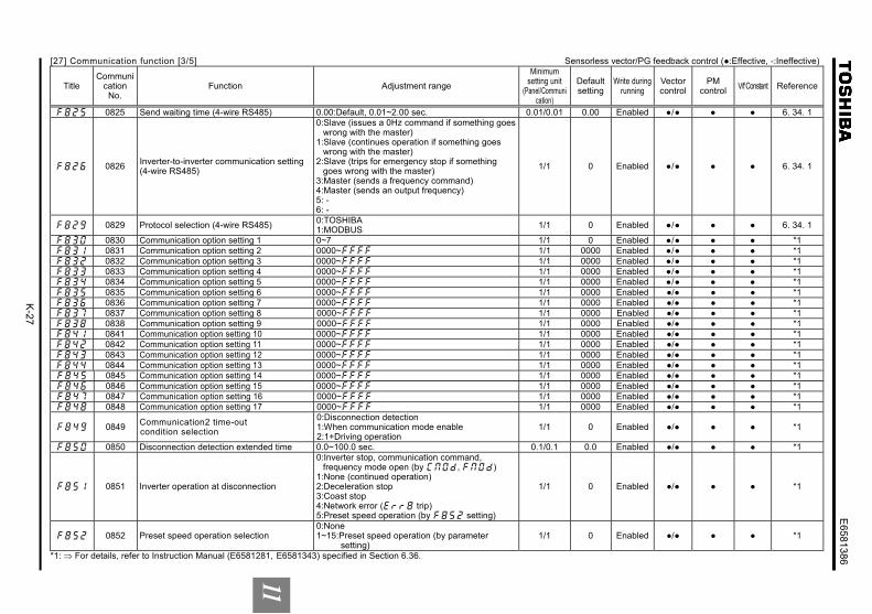
[27] Communication function [3/5] Sensorless vector/PG feedback control (:Effective, -:Ineffective)
Title Communi
cation No.
Function Adjustment range
Minimum setting unit
(Panel/Communication)
Default setting
Write during running
Vector control
PM control
V/f Constant Reference
0825 Send waiting time (4-wire RS485) 0.00:Default, 0.01~2.00 sec. 0.01/0.01 0.00 Enabled / 6. 34. 1
0826 Inverter-to-inverter communication setting (4-wire RS485)
0:Slave (issues a 0Hz command if something goes wrong with the master)
1:Slave (continues operation if something goes wrong with the master)
2:Slave (trips for emergency stop if something goes wrong with the master)
3:Master (sends a frequency command) 4:Master (sends an output frequency) 5: - 6: -
1/1 0 Enabled / 6. 34. 1
0829 Protocol selection (4-wire RS485) 0:TOSHIBA 1:MODBUS
1/1 0 Enabled / 6. 34. 1
0830 Communication option setting 1 0~7 1/1 0 Enabled / *1
0831 Communication option setting 2 0000~ 1/1 0000 Enabled / *1
0832 Communication option setting 3 0000~ 1/1 0000 Enabled / *1
0833 Communication option setting 4 0000~ 1/1 0000 Enabled / *1
0834 Communication option setting 5 0000~ 1/1 0000 Enabled / *1
0835 Communication option setting 6 0000~ 1/1 0000 Enabled / *1
0836 Communication option setting 7 0000~ 1/1 0000 Enabled / *1
0837 Communication option setting 8 0000~ 1/1 0000 Enabled / *1
0838 Communication option setting 9 0000~ 1/1 0000 Enabled / *1
0841 Communication option setting 10 0000~ 1/1 0000 Enabled / *1
0842 Communication option setting 11 0000~ 1/1 0000 Enabled / *1
0843 Communication option setting 12 0000~ 1/1 0000 Enabled / *1
0844 Communication option setting 13 0000~ 1/1 0000 Enabled / *1
0845 Communication option setting 14 0000~ 1/1 0000 Enabled / *1
0846 Communication option setting 15 0000~ 1/1 0000 Enabled / *1
0847 Communication option setting 16 0000~ 1/1 0000 Enabled / *1
0848 Communication option setting 17 0000~ 1/1 0000 Enabled / *1
0849 Communication2 time-out condition selection
0:Disconnection detection 1:When communication mode enable 2:1+Driving operation
1/1 0 Enabled / *1
0850 Disconnection detection extended time 0.0~100.0 sec. 0.1/0.1 0.0 Enabled / *1
0851 Inverter operation at disconnection
0:Inverter stop, communication command, frequency mode open (by , )
1:None (continued operation) 2:Deceleration stop 3:Coast stop 4:Network error ( trip) 5:Preset speed operation (by setting)
1/1 0 Enabled / *1
0852 Preset speed operation selection 0:None 1~15:Preset speed operation (by parameter
setting) 1/1 0 Enabled / *1
*1: ⇒ For details, refer to Instruction Manual (E6581281, E6581343) specified in Section 6.36.

K-2
8
E6581386
11
[27] Communication function [4/5] Sensorless vector/PG feedback control (:Effective, -:Ineffective)
Title Communi
cation No.
Function Adjustment range
Minimum setting unit
(Panel/Communication)
Default setting
Write during running
Vector control
PM control
V/f Constant Reference
0853 Communication option station address monitor
0~255 1/1 0 Enabled / *1
0854 Communication option speed switch monitor DeviceNet/CC-Link
0~255 1/1 0 Enabled / *1
0856 Number of motor poles for communication
1:2 poles 2:4 poles 3:6 poles 4:8 poles 5:10 poles 6:12 poles 7:14 poles 8:16 poles
1/1 2 Enabled / *1
0870 Block write data 1
0:Disabled 1:Command information 1 2:Command information 2 3:Frequency command 4:Terminal board output data 5:Communication analog data 6:Rotational speed command
1/1 0 Enabled / 6. 34. 1
0871 Block write data 2 Ditto 1/1 0 Enabled / 6. 34. 1
0875 Block read data 1
0:Deselect 1:Status information 2:Output frequency 3:Output current 4:Output voltage 5:Alarm information 6:PID feedback value 7:Input terminal board monitor 8:Output terminal board monitor 9:VI/II terminal board monitor 10:RR/S4 terminal board monitor 11:RX terminal board monitor 12:Input voltage (DC detection) 13:Speed feedback frequency 14:Torque 15:MY monitor 1 16:MY monitor 2 17:MY monitor 3 18:MY monitor 4 19:Free notes 20:Rotational speed
1/1 0 Enabled / 6. 34. 1
*1: ⇒ For details, refer to Instruction Manual (E6581281, E6581343, E6581477) specified in Section 6.36.

K-2
9
E6581386
11
[27] Communication function [5/5] Sensorless vector/PG feedback control (:Effective, -:Ineffective)
Title Communi
cation No.
Function Adjustment range
Minimum setting unit
(Panel/Communication)
Default setting
Write during running
Vector control
PM control
V/f Constant Reference
0876 Block read data 2 Ditto 1/1 0 Enabled / 6. 34. 1
0877 Block read data 3 Ditto 1/1 0 Enabled / 6. 34. 1
0878 Block read data 4 Ditto 1/1 0 Enabled / 6. 34. 1
0879 Block read data 5 Ditto 1/1 0 Enabled / 6. 34. 1
0880 Free notes 0~ 1/1 0 Enabled / 6. 34. 1
0899 Network option reset setting 0:None 1:Reset option circuit board and inverter
1/1 0 Disabled / *1
*1: ⇒ For details, refer to Instruction Manual (E6581281, E6581343, E6581477) specified in Section 6.36. [28] My function [1/5] Sensorless vector/PG feedback control (:Effective, -:Ineffective)
Title Communi
cation No.
Function Adjustment range
Minimum setting unit
(Panel/Communication)
Default setting
Write during running
Vector control
PM control
V/f Constant Reference
0900 Input function target 11
Input terminal function number 0:Deselect 1:F terminal 2:R terminal 3:- 4:RES terminal 5:S1 terminal 6:S2 terminal 7:S3 terminal 8:RR/S4 terminal 9:LI1 terminal 10:LI2 terminal 11:LI3 terminal 12:LI4 terminal 13:LI5 terminal 14:LI6 terminal 15:LI7 terminal 16:LI8 terminal 17:B12 terminal 18:B13 terminal 19:B14 terminal 20:B15 terminal 21:Virtual input terminal 1 22:Virtual input terminal 2 23:Virtual input terminal 3 24:Virtual input terminal 4 25~32:Internal terminal 1~8 918~934:MY function number 1000~1255:Output selection number 2000~2099:FD00~FD99 3000~3099:FE00~FE99
1/1 0 Disabled / *1
*1: ⇒ For details, refer to Instruction Manual (E6581335) specified in Section 6.36.

K-3
0
E6581386
11
[28] My function [2/5] Sensorless vector/PG feedback control (:Effective, -:Ineffective)
Title Communi
cation No.
Function Adjustment range
Minimum setting unit
(Panel/Communication)
Default setting
Write during running
Vector control
PM control
V/f Constant Reference
0901 Input function command 12
0:NOP (not operation) 1:ST (move) 2:STN 3:AND (logical product) 4:ANDN 5:OR (logical sum) 6:ORN 7:EQ (equal) 8:NE (not equal) 9:GT (greater than) 10:GE (greater or equal) 11:LT (less than) 12:LE (less or equal) 13:ASUB (absolute) 14:ON (on delay timer) 15:OFF (off delay timer) 16:COUNT 1 (counter 1) 17:COUNTR 2 (counter 2) 18:HOLD (hold) 19:SET (set) 20:RESET (reset) 21:CLR 22:CLRN
1/1 0 Disabled / *1
0902 Input function target 12 Same as 1/1 0 Disabled / *1
0903 Input function command 13 Same as 1/1 0 Disabled / *1
0904 Input function target 13 Same as 1/1 0 Disabled / *1
0905 Output function assigned object 1 Same as 1/1 0 Disabled / *1
0906 Input function target 21 Same as 1/1 0 Disabled / *1
0907 Input function command 22 Same as 1/1 0 Disabled / *1
0908 Input function target 22 Same as 1/1 0 Disabled / *1
0909 Input function command 23 Same as 1/1 0 Disabled / *1
0910 Input function target 23 Same as 1/1 0 Disabled / *1
0911 Output function assigned object 2 Same as 1/1 0 Disabled / *1
0912 Input function target 31 Same as 1/1 0 Disabled / *1
0913 Input function command 32 Same as 1/1 0 Disabled / *1
*1: ⇒ For details, refer to Instruction Manual (E6581335) specified in Section 6.36.

K-3
1
E6581386
11
[28] My function [3/5] Sensorless vector/PG feedback control (:Effective, -:Ineffective)
Title Communi
cation No.
Function Adjustment range
Minimum setting unit
(Panel/Communication)
Default setting
Write during running
Vector control
PM control
V/f Constant Reference
0914 Input function target 32 Same as 1/1 0 Disabled / *1
0915 Input function command 33 Same as 1/1 0 Disabled / *1
0916 Input function target 33 Same as 1/1 0 Disabled / *1
0917 Output function assigned object 3 Same as 1/1 0 Disabled / *1
0918 My output percent data 1 0.00~200.0% 0.01/0.01 0.00 Enabled / *1
0919 My output percent data 2 0.00~200.0% 0.01/0.01 0.00 Enabled / *1
0920 My output percent data 3 0.00~200.0% 0.01/0.01 0.00 Enabled / *1
0921 My output percent data 4 0.00~200.0% 0.01/0.01 0.00 Enabled / *1
0922 My output percent data 5 0.00~200.0% 0.01/0.01 0.00 Enabled / *1
0923 My output frequency data 1 0.0~500.0Hz 0.1/0.1 0.0 Enabled / *1
0924 My output frequency data 2 0.0~500.0Hz 0.1/0.1 0.0 Enabled / *1
0925 My output frequency data 3 0.0~500.0Hz 0.1/0.1 0.0 Enabled / *1
0926 My output frequency data 4 0.0~500.0Hz 0.1/0.1 0.0 Enabled / *1
0927 My output frequency data 5 0.0~500.0Hz 0.1/0.1 0.0 Enabled / *1
0928 My output time data 1 0.01~600.0sec 0.01/0.01 0.01 Enabled / *1
0929 My output time data 2 0.01~600.0sec 0.01/0.01 0.01 Enabled / *1
0930 My output time data 3 0.01~600.0sec 0.01/0.01 0.01 Enabled / *1
0931 My output time data 4 0.01~600.0sec 0.01/0.01 0.01 Enabled / *1
0932 My output time data 5 0.01~600.0sec 0.01/0.01 0.01 Enabled / *1
0933 No. of times of My output data 1 0~9999 times 1/1 0 Enabled / *1
0934 No. of times of My output data 2 0~9999 times 1/1 0 Enabled / *1
0935 Input function target 41 Same as 1/1 0 Enabled / *1
0936 Input function command 42 Same as 1/1 0 Enabled / *1
0937 Input function target 42 Same as 1/1 0 Enabled / *1
0938 Input function command 43 Same as 1/1 0 Enabled / *1
0939 Input function target 43 Same as 1/1 0 Enabled / *1
0940 Output function assigned object 4 Same as 1/1 0 Enabled / *1
0941 Input function target 51 Same as 1/1 0 Enabled / *1
0942 Input function command 52 Same as 1/1 0 Enabled / *1
0943 Input function target 52 Same as 1/1 0 Enabled / *1
0944 Input function command 53 Same as 1/1 0 Enabled / *1
0945 Input function target 53 Same as 1/1 0 Enabled / *1
0946 Output function assigned object 5 Same as 1/1 0 Enabled / *1
*1: ⇒ For details refer to the Instruction Manual (E6581335) for this parameter.

K-3
2
E6581386
11
[28] My function [4/5] Sensorless vector/PG feedback control (:Effective, -:Ineffective)
Title Communi
cation No.
Function Adjustment range
Minimum setting unit
(Panel/Communication)
Default setting
Write during running
Vector control
PM control
V/f Constant Reference
0947 Output function target 61 Same as 1/1 0 Enabled / *1
0948 Input function command 62 Same as 1/1 0 Enabled / *1
0949 Input function target 62 Same as 1/1 0 Enabled / *1
0950 Input function command 63 Same as 1/1 0 Enabled / *1 0951 Input function target 63 Same as 1/1 0 Enabled / *1 0952 Output function assigned object 6 Same as 1/1 0 Enabled / *1 0953 Input function target 71 Same as 1/1 0 Enabled / *1 0954 Input function command 72 Same as 1/1 0 Enabled / *1 0955 Input function target 72 Same as 1/1 0 Enabled / *1 0956 Input function command 73 Same as 1/1 0 Enabled / *1 0957 Input function target 73 Same as 1/1 0 Enabled / *1 0958 Output function assigned object 7 Same as 1/1 0 Enabled / *1
0959 Analog input function target 11
0:Disabled 1:VI/II 2:RR/S4 3:RX 4:Optional AI1+, Optional AI1- 5:Optional AI2 6:Internal memory1
1/1 0 Enabled / *1
0961 Analog function assigned object 11
0:Disabled 1:Acceleration 2:Upper limit frequency ( ) 3:Acceleration multiplication factor 4:Deceleration multiplication factor 5:Manual torque boost ( ) 6:OC stall ( ) 7:Thermal protection ( ) 8:Speed loop P gain ( ) 9:Drooping gain ( ) 10:PID P gain ( )
1/1 0 Disabled / *1
*1: ⇒ For details, refer to Instruction Manual (E6581335) specified in Section 6.36.

K-3
3
E6581386
11
[28] My function [5/5] Sensorless vector/PG feedback control (:Effective, -:Ineffective)
Title Communi
cation No.
Function Adjustment range
Minimum setting unit
(Panel/Communication)
Default setting
Write during running
Vector control
PM control
V/f Constant Reference
0962 Analog input function target 21
0:Disabled 1:VI/II 2:RR/S4 3:RX 4:Optional AI1+, Optional AI1- 5:Optional AI2 6:Internal memory2
1/1 0 Enabled / *1
0964 Analog function assigned object 21 0~10 1/1 0 Disabled / *1
0965 Monitor output function target 11 2000~2099:FD00~FD99 3000~3099:FE00~FE99
1/1 2000 Enabled / *1
0966 Monitor output function command 11 0:Normal monitor 1:Max. value 2:Min. value
1/1 0 Enabled / *1
0967 Monitor output function target 21 2000~2099:FD00~FD99 3000~3099:FE00~FE99
1/1 2000 Enabled / *1
0968 Monitor output function command 21 0:Normal monitor 1:Max. value 2:Min. value
1/1 0 Enabled / *1
0969 Monitor output function target 31 2000~2099:FD00~FD99 3000~3099:FE00~FE99
1/1 2000 Enabled / *1
0970 Monitor output function command 31 0:Normal monitor 1:Max. value 2:Min. value
1/1 0 Enabled / *1
0971 Monitor output function target 41 2000~2099:FD00~FD99 3000~3099:FE00~FE99
1/1 2000 Enabled / *1
0972 Monitor output function command 41 0:Normal monitor 1:Max. value 2:Min. value
1/1 0 Enabled / *1
0973 Virtual input terminal selection 1 0~135 *2 1/1 0 Disabled / *1
0974 Virtual input terminal selection 2 0~135 *2 1/1 0 Disabled / *1
0975 Virtual input terminal selection 3 0~135 *2 1/1 0 Disabled / *1
0976 Virtual input terminal selection 4 0~135 *2 1/1 0 Disabled / *1
0977 My function selection 0:Disabled 1:My function + permission signal 2:My function always ON
1/1 0 Disabled / *1
*1: ⇒ For details, refer to Instruction Manual (E6581335) specified in Section 6.36. *2: ⇒ For the adjustment range, see the table on page K-38


![POWER QUALITY IMPROVEMENT OF PHOTOVOLTAIC ...parameters [14] are given in Table-3. Table- 3. Three phase induction motor parameters. Parameter Value Rated Power 4 Kw Rated Line to](https://img.dokumen.tips/doc/110x75/607a744e9e3a7a017a48e4d1/power-quality-improvement-of-photovoltaic-parameters-14-are-given-in-table-3.jpg)