Embed Size (px)
Citation preview
8/9/2019 11-820 Installation Procedure
http://slidepdf.com/reader/full/11-820-installation-procedure 1/27
Gate System Installation ProcedureWedge Air Bladder
Junquillo 11-820
Table of Contents
1.0 SCOPE OF THIS DOCUMENT
2.0 GATE SYSTEM DEFINITIONS3.0 ABUTMENT PLATE INSTALLATION4.0 MAIN ANCHOR BOLT INSTALLATION5.0 AIR PIPING6.0 FOUNDATION FINISH, EMBEDDED PNEUMATIC PIPING,
CONDENSATE PURGE LINE and INCLINOMETER CONDUIT7.0 SPILLWAY GATES8.0 INSTALLATION OF INTER-PANEL SEALS9.0 ABUTMENT & J-BULB SEAL INSTALLATION10.0 RESTRAINING STRAPS11.0 LOCATING AND ANCHORING AIR SUPPLY, ACC and PLC12.0 ELECTRICAL13.0 FIELD TESTING14.0 TORQUES AND TOOLS15.0 COMMON CONSTRUCTION ERRORS AND TIPS16.0 CHECK LISTS
16.1 Abutment Plate16.2 Main Anchor Bolt16.3 Concrete
Created By Approved Date Revision No.
PAC Sept 18, 2013 Created Install Procedure 1
OBERMEYER HYDRO, INC. This Document is property of Obermeyer Hydro, Inc.and is not to be used, disclosed, reproduced ortransmitted by electronic or any other means withoutprior written authorization from OHI.
COPYRIGHTED, OBERMEYER HYDRO, INC.,2005
PO BOX 668, FORT COLLINS,
CO 80522 TEL 970-568-9844
FAX 970-568-9845

8/9/2019 11-820 Installation Procedure
http://slidepdf.com/reader/full/11-820-installation-procedure 2/27
GATE SYSTEM INSTALLATION PROCEDURE Printed: 9/18/2013Junquillo 11-820
OBERMEYER Hydro Inc. 2 of 27
1.0 SCOPE OF THIS DOCUMENT
Note: This is a general guide only. Actual field conditions may dictate differentconstruction methods.
This procedure is to be used by the CONTRACTOR installing the OHI gate system. Thisdocument is divided into several sections:
• Definition of spillway gate components.• Civil works: Installation of Abutment Plates, Main & Restraining Strap Anchor
Bolts, Spillway Finish, and Pneumatic Piping.• Spillway Gates: Installation of the Gate Panels, Air Bladders, Hinges, Clamp
Castings, Seals & Restraining Straps and other associated hardware.•
Installation of air controls including Air Compressor, Blowers, ACC and PLCCabinets.• Site specific construction requirements to follow torque values, and tolerances
set by design drawings and proper construction tools required• OHI field inspection responsibilities
General Notes: Use anti-seize compound on all threads. Use Teflon tape and threadsealant compound “pipe dope” on all air fittings. Caulk must be 100% silicone oraquarium grade. Silicone will not bond to wet surfaces, so keep them clean and dry.Keep sharp objects and surfaces away from rubber parts.

8/9/2019 11-820 Installation Procedure
http://slidepdf.com/reader/full/11-820-installation-procedure 3/27
GATE SYSTEM INSTALLATION PROCEDURE Printed: 9/18/2013Junquillo 11-820
OBERMEYER Hydro Inc. 3 of 27
2.0 GATE SYSTEM DEFINITIONS
The spillway gate assembly comprises the components found on the spillway andincludes the air bladders, gate panels, anchor bolts, etc. The air bladders inflate to raisethe gate system and deflate to lower the gate system.
GATE PANELThe Gate Panel acts as a movable, rigid barrier to the water. The Gate Panels attachalong the upstream edge to the Hinge Flap. Two adjacent Gate Panels are connectedtogether using the Inter-Panel Seal.
MAIN ANCHOR ASSEMBLY
The gate and bladder system are anchored to the spillway with the Main AnchorAssembly. The Main Anchor Assembly is a continuous fabricated steel unit that spansthe channel’s width and has a series of anchor bolts that fasten the assembly to thespillway. In some cases this may be a series of studs anchored to the spillway,depending on construction techniques. These are large studs extending upwards fromthe assembly, which are used to fasten the Air Bladder, Hinge Flap, Inner-Panel Seal,and Abutment Seals via clamp castings. The Main Anchor Assembly therefore evenlytransmits the larger hydrostatic forces generated by the Gate Panel downward into theconcrete. It also provides for water stop under the bladder.
AIR BLADDERThe Air Bladders rest on top of the spillway and are held in place by Clamp Castingsthat mount to the upstream edge of the spillway. When inflated, the Air Bladder impartsthe upward and upstream force on the Gate Panel that impounds the water. The aircontrol system is connected to the underside of the Air Bladder by means of a threadedfitting and flexible hose.
The Hinge FlapHinge Flap connects the Gate Panel to the dam surface and acts as a water seal. Theupstream wedge section is compressed along with the Air Bladder wedge sections inthe Clamp Castings. The downstream portion of the Hinge Flap connects to the GatePanel using the bottom row of Gate Panel studs with the provided Hinge Flap Retainers,washers and hex nuts. In the fully raised position, with the Air Bladder inflated, theHinge Flap transmits a compressive force from the Clamp Castings to the bottom edgeof the Gate Panel.
NOTE: Inflation of an Air Bladder, even under low pressure, without clampssecurely tightened, can cause permanent damage or rupture of the Air Bladders.The Air Bladder should never be inflated unless properly installed.

8/9/2019 11-820 Installation Procedure
http://slidepdf.com/reader/full/11-820-installation-procedure 4/27
GATE SYSTEM INSTALLATION PROCEDURE Printed: 9/18/2013Junquillo 11-820
OBERMEYER Hydro Inc. 4 of 27
CLAMP CASTINGS
The Clamp Castings are positioned over the Main Anchor Bolts and retain the AirBladder and Hinge Flap in place. The Clamp Castings transmit a force to the bottomedge of the Gate Panel through the Hinge Flap. This force, and the force imparted tothe Gate Panel by the inflated portion of the Air Bladder, provides the moment requiredto support the cantilevered Gate Panel. The Clamp Castings also provide the sealingmechanism for the Air Bladder.
HINGE FLAP RETAINERSThe Hinge Flap Retainers clamp the Hinge Flap to the upstream edge of the GatePanel. With the gate fully raised or fully lowered, the forces tending to pull the HingeFlap out from under the Hinge Flap Retainers are low. At intermediate gate positions,
high forces occur, which requires the Hinge Flap Retainers be kept tightly clamped.
RESTRAINING STRAPSThe Restraining Straps are the reinforced rubber strips that attach to the spillway and tothe bottom side of the Gate Panel. The Restraining Strap limits the upstream travel andheight of the Gate Panel during inflation and insures that the Gate Panel does not flipover upstream when the gate system is fully raised and the water elevation is less thanfull pond depth.
RESTRAINING STRAP CLAMPSThe Restraining Strap Clamps fasten the Restraining Strap to the spillway and to the
Gate Panel. The Restraining Strap Anchor Bolts used to fasten the clamp to thespillway and the hex head bolts used to fasten the clamp to the Gate Panel are typicallyof the same diameter and should be kept tight at all times.
NAPPE BREAKERSThe Nappe Breakers divide the water flowing over the top edge of the raised gatesystem. This provides an air path to the otherwise closed off space under the raisedGate Panel created by the water wall. Without the Nappe Breakers, a vacuum couldoccur behind the water wall and high gate loads or vibration may occur.
ABUTMENT PLATESThe Abutment Plates may consist of concrete, stainless steel or UHMW polyurethane.The Abutment Plate component is located at each section end of the gate system. Itprovides a smooth vertical surface for the Abutment Seal that is attached at each end ofthe Gate system to create a watertight seal.
ABUTMENT SEALSThe Abutment Seals are the reinforced rubber strip that seals the end Gate Panels tothe Abutment Plates.

8/9/2019 11-820 Installation Procedure
http://slidepdf.com/reader/full/11-820-installation-procedure 5/27
GATE SYSTEM INSTALLATION PROCEDURE Printed: 9/18/2013Junquillo 11-820
OBERMEYER Hydro Inc. 5 of 27
Flow
LEFT
RIGHT
NOTE: Left andRight are definedby lookingdownstream (intoflow)
G A T E
ORIENTATION

8/9/2019 11-820 Installation Procedure
http://slidepdf.com/reader/full/11-820-installation-procedure 6/27
GATE SYSTEM INSTALLATION PROCEDURE Printed: 9/18/2013Junquillo 11-820
OBERMEYER Hydro Inc. 6 of 27
3.0 ABUTMENT PLATE INSTALLATION
1. Abutment plate dimensions, materials, and construction for this project are detailedon project drawings 11-820-240L-F&R and 11-820-240R-F&R.
2. Installation and construction methods are provided on drawings 11-820-112 and 11-820-240L-F&R & 240R-F&R. Contractor to form abutment walls. These plates maybe installed during the initial construction of the abutment walls or with the requiredblock-out for later installation depending on the contractors preferred method.Stainless Steel Abutment Plates will be positioned and adjusted in the block outspace using Contractor provided hardware so that they are plumb to within 3mm and are perpendicular to the Main Anchor Bolt centerline. The Abutment Plate toAbutment Plate distance must be maintained pursuant to the construction drawings
to within 6mm. The Abutment Plate must be installed so that it is coplanar to within6mm.
3. The plates must be secure and capable of withstanding the hydrostatic forces thegrout placed behind the plates creates. Any shifting of the Abutment Plates duringgrouting may require the removal of the plate and reinstallation, at the Contractor’sexpense.
4. Tolerances for Abutment Plate installation are critical.

8/9/2019 11-820 Installation Procedure
http://slidepdf.com/reader/full/11-820-installation-procedure 7/27
GATE SYSTEM INSTALLATION PROCEDURE Printed: 9/18/2013Junquillo 11-820
OBERMEYER Hydro Inc. 7 of 27
4.0 MAIN ANCHOR BOLT INSTALLATION
NOTE: Under no circumstances will welding of any metal to the anchor bolts be allowed.Unapproved heating of the bolts could lead to failure of the anchoring system.
1. Formation of the concrete cross section where the Main Anchor Clamp Casting sitswill be made using OHI provided foam forms. Refer to drawings 11-820-207-A5-1through 11-820-A5-3.
2. Contractor will secure into place the provided OHI foam forms. Contractor will checkthat form placement does not interfere with any expansion joints in the concretespillway.
3. Refer to drawings 11-820-101,102 for plan view detail layout of Main Anchor Boltlocations. Refer to drawing 11-820-111 for section view of Main Anchor Bolt detailedlayout.
4. The Pivot Embed (See drawings 11-820-208-1 through 11-820-208-3) and WedgeEmbed (See drawings 11-820-209-1 through 11-820-209-3) are fastened to the OHIfoam form. Refer to drawing 11-820-102 for assembly of embeds to the foam forms.
5. Contractor to ensure the OHI foam form pans are firmly secured using tie rods thatare embedded in concrete as needed. Contractor to finalize method of fastening tierods. Contractor can submit anchorage methods to Obermeyer Hydro for ideas and
approval.
6. After pouring of concrete, Contractor to apply extra vibration near the forms toensure no air pockets form under the foam forms. Honeycomb formation under theOHI foam form pans, Pivot & Wedge Embeds, or around the Main Anchors Boltsshall be avoided.
7. Contractor to ensure Main Anchor Bolts are to be 142mm above finished concretesurface. Refer to drawing 11-820-111 for section view.
8. After concrete has cured, the Pivot & Wedge Embed studs welded to the embedangles shall be cutoff and ground flush. All grinding must be done with a new ornon-contaminated grinding media.
9. Restraining Strap Anchor Bolts may be poured in place or core drilled and epoxy setto adhere bolt to concrete. Drawing 11-820-101 gives plan view detailed locationlayout of bolts. Drawing 11-820-111 gives section view of bolts in relation to MainAnchor Bolts.
10. Restraining Strap Anchors are to be 102mm above finished surface in concreteblock-out. Refer to drawing 11-820-111 for section view.

8/9/2019 11-820 Installation Procedure
http://slidepdf.com/reader/full/11-820-installation-procedure 8/27
GATE SYSTEM INSTALLATION PROCEDURE Printed: 9/18/2013Junquillo 11-820
OBERMEYER Hydro Inc. 8 of 27
5.0 AIR PIPING
1. The piping between the Main Air Supply and Air Control Cabinet (ACC) shouldhave a working pressure of at least 150 psig. The piping between the Air Bladdersand the Air Control Cabinet will normally contain pressures less than 50 psig.
2. All piping should be blown out with air to remove any scale or debris prior toconnection to the ACC or the Air Bladders.
3. Providing all piping and wiring and the installation of all piping and wiring is theresponsibility of the Contractor. Installation of the compressors, blowers, dryers,filters, tanks, drain valves, ACC and associated equipment is the responsibility ofthe Contractor.
4. Contractor to provide means of removing condensate from air line at low point ofair pipe system or at control side abutment. Refer to drawing 11-820-125 forrecommended details of condensate purge locations.
5. Any exposed portions of the piping shall be securely supported, as outlined in thelocal building code or project specification.
6. All air piping shall utilize welded fittings. All welding to be in accordance with AWSStructural Welding Specifications. All pipe joints to be leak proof.
7. Before installation of gate system, the entire run of pipe and connections shall beinspected and pressure tested to 50 psig and each joint checked for leaks with theowner’s representative present.
8. All electrical conduit shall be up to code and as specified in the plans
9. Piping at expansion joints to be sleeved to allow for movement of concrete.
10. All piping and conduit shall be rigid, except that flexible metal conduit may be usedin short lengths where needed to connect to vibrating equipment.
THE LOWEST POINT OF ALL AIR SUPPLY LINES MUST BE AT THECONDENSATE PURGE

8/9/2019 11-820 Installation Procedure
http://slidepdf.com/reader/full/11-820-installation-procedure 9/27
GATE SYSTEM INSTALLATION PROCEDURE Printed: 9/18/2013Junquillo 11-820
OBERMEYER Hydro Inc. 9 of 27
6.0 FOUNDATION FINISH, EMBEDDED PNEUMATIC PIPING,CONDENSATE PURGE LINE and INCLINOMETER CONDUIT
1. Embedded Air Piping
a) The air supply pipes between the gate and the air control cabinet shall betested prior to final embedment in concrete by pressurizing to 50 psi for acontinuous 24 hour period. Pressure readings and ambient air temperatureshall be recorded at six different times during the test.
b) A wet test of the air lines may be performed with a leak detection solution at 50psi in place of the 24 hour timed test.
c) Any joints or fittings exhibiting leakage during this time shall be repaired orreplaced.
2. The concrete area along the spillway crest to which the clamping assembly is to bebolted shall be made level and flat with a high quality smooth surface. The areasthat supports the bladders will be made smooth (trowel finish) and shall be free ofsharp or abrasive objects or protrusions, which could damage the air bladder.
3. The pneumatic and conduit piping shall be placed in accordance with the drawings.A plan view of the conceptual pneumatic & conduit piping layout are shown indrawing 11-820-101 & 125. Contractor to review drawing to ensure PneumaticPiping, Inclinometer, and Condensate Purge Line(s) are correct size.
4. See drawing 11-820-111 for section elevation view of Main Air Supply & Air Block-Out detailed layout.
5. Contractor’s scope to include piping stub out into the air-connection block-out thatterminates with a female thread. See drawing 11-820-123 for details.
6. Contractor to provide for and construct Condensate Purge Valve(s) at low point(s)in piping system. See drawing 11-820-125 for recommended section view ofpiping layout.

8/9/2019 11-820 Installation Procedure
http://slidepdf.com/reader/full/11-820-installation-procedure 10/27
GATE SYSTEM INSTALLATION PROCEDURE Printed: 9/18/2013Junquillo 11-820
OBERMEYER Hydro Inc. 10 of 27
7.0 SPILLWAY GATES
Bladders, Hinges, and Gate Panels
1. Spillway Prep: Clean spillway of dirt & debris, especially wedge area. Wire brushanchor bolt threads to remove any concrete splatter. Repair damaged threads with3-corner file or proper die size.
*** USE COPPER OR NICKEL-BASED ANTI-SEIZE LUBRICANT ON ALLTHREADS ***
2. Locate Gate Panels.
3. Locate Air Bladder and Hinge Flaps.
4. Prior to bolting respective Gate Panels together, apply silicon for each Gate Flangeand around bolt holes. Set aside. See pic. 4.1 and drawing 11-820-120-1.
pic 4.1
5. Install Hinge Flaps onto Gates Panel using Hinge Retainers and stainless steelfastening hardware. On larger gates it may be necessary to cut the hinge andinstall it in multiple sections. (use generous amounts of copper or nickel-basedanti-seize lubricant on all stainless steel threads)
6. On the Gate Panel apply silicon around all the threaded holes and one big beadalong the joint or the round stock and flat as well as up and over where the ribscome into the round stock (see pic 4.2).

8/9/2019 11-820 Installation Procedure
http://slidepdf.com/reader/full/11-820-installation-procedure 11/27
GATE SYSTEM INSTALLATION PROCEDURE Printed: 9/18/2013Junquillo 11-820
OBERMEYER Hydro Inc. 11 of 27
pic 4.2
7. Locate Air Bladders and miscellaneous air plumbing hardware.
a. Attach ¾” brass elbow to brass bulkhead fitting located on bottom surfaceof Air Bladder.
b. Connect ¾” stainless steel barb to end of Contractor supplied air piping.
8. Refer to drawing 11-820-123 to install air assembly (Use Teflon tape and “pipedope” on all screw type pipe fittings).
a. Locate the precut ¾” Poly reinforced hose with the stainless spiral insert.
b. Bend the end of the spiral insert so it will not slip over the end of the hose
barb during installation. Measure the length of the spiral insert and makesure it will span the length between the hose barbs, minus the plastic insert.
c. Insert the clear plastic insert in the hose between the stainless spiral andthe brass barbed fitting on the bladder and clamp the hose to the brassfitting with provided Mikalor clamp.
9. Position the wedge of Air Bladder on spillway just downstream of Main AnchorBolts. The wedge should touch the upstream wall of the wedge embed. Makesure the Air Bladder fitting fits correctly into Air Block-Out.
Silicon

8/9/2019 11-820 Installation Procedure
http://slidepdf.com/reader/full/11-820-installation-procedure 12/27
GATE SYSTEM INSTALLATION PROCEDURE Printed: 9/18/2013Junquillo 11-820
OBERMEYER Hydro Inc. 12 of 27
10. Roll the Air Bladder in half from left to right, or lift the wedge of the bladder toexpose Air Bladder connection.
a Loop the hose back around to the stainless fitting and secure with providedMikalor clamp
b Fill the Air Block-Out with expandable foam isolation, in geographicallocations where freezing is present.
11. Roll Air Bladder into final position. Make sure the air supply line does not kink.
12. Repeat steps 4 thru 11 for remaining Air Bladder(s).
13. Apply generous amounts of copper or nickel-based anti-seize lubricant on allstainless steel threads.
14. Place assembled Gate Panel/Hinge Flaps onto Air Bladders. Reference drawing11-820-110 for section view. Align the upstream edge of Hinge Flap with the AirBladder wedges. The upstream profile of the two 30° degree Air Bladder wedgesand the single Hinge Flap 30° degree wedge should follow a circular 90° degreearc.
15. Locate Main Anchor Clamp Castings. Position Main Anchor Clamp Castings overthe Air Bladder and Hinge Flap wedges so the hinge wedge is tight against the
arch of the clamp. Make sure to use generous amounts of copper or nickel-basedanti-seize lubricant on all stainless steel threads and on bearing surfaces ofstainless steel nuts. Tighten nuts enough to get the next clamp placed
16. Install Abutment Seals. Refer to Section 8.0
17.Do not torque anchor bolts or inflate the system until the Abutment Seals areinstalled.
18. Tighten stainless steel hex nuts starting at the Abutment Seals working toward themiddle of each bladder. After all nuts are snug (135-270 N-m), torque to 1400 N-m, working from the ends of the bladders to the middle. Make sure the mainanchors are tightened evenly to keep the clamp even. Make sure to use generousamounts of copper or nickel-based anti-seize lubricant on all stainless steelthreads and on bearing surfaces of stainless steel nuts.
19. Repeat steps 14 through 18 for remaining Gate Panel(s). Double check theabutment-to-abutment direction measurement after placing each gate, to ensurethat Gate Panels and Air Bladders are set correctly.
20. Beginning at the Abutment seal and working toward the center of the Air Bladder,re-torque each of the Main Anchor Bolts to 1400 N-m

8/9/2019 11-820 Installation Procedure
http://slidepdf.com/reader/full/11-820-installation-procedure 13/27
GATE SYSTEM INSTALLATION PROCEDURE Printed: 9/18/2013Junquillo 11-820
OBERMEYER Hydro Inc. 13 of 27
21. Starting at one end re-torque all Main Anchor Bolts to 1400 N-m.
22. Wait 24 hours and again torque all anchor bolts 1400 N-m. (Note: 1400 N-m isan estimated only, temperature affects on the rubber may require a higher torquevalue to seat rubber into casting)
23. Inflate gate system to proper height of 3 M and then lower the gate and re-torquethe bolts.
• CAUTION: Be careful when inflating the system at this time. Since theRestraining Straps are not installed yet, the gates can tip over upstream if raisedto far. See Section 9.0 to install the Restraining Straps.
•
24. Install Nappe Breakers on downstream top edge of each Gate Panel.
8.0 ABUTMENT SEAL INSTALLATION
NOTE: Cold vulcanize seals at joint areas. Install Abutment Seals before vulcanizing inorder to maximize the time sensitive materials involved in the process. See vulcanizationtechnique in OHI-SPEC-3004 and drawing 11-820-120-1 for cross sectional views.
1. The Abutment Seals incorporate a 30° degree wedge section at the upstream end(same as the Hinge Flap). Trim back Hinge Flap so the Abutment Seal wedgesection fits snuggly against the Hinge Flap section. Allowing a 3mm interference
on each side works well. Test fit Abutment Seal, securely positioning the wedgebetween the Hinges.
2. Use anti-seize lubricant or marking paint, coat the tops of the studs holding theAbutment Seal. By hand, push the Abutment Seal against the Abutment Plate sothe flat sealing surface of the seal is flush with the Abutment Plate. This is so theseal will have tension on the Abutment Plate and make a seal. Holding it in place,hit the seal with the sledge hammer directly over the first stud, marking theunderside of the seal. This marks the upstream to downstream location.
3. Measure the distance from the first stud to the Abutment Wall. Transpose that
measurement onto the Abutment Seal and mark location (Measurement A).Measure from bladder side the distance to marked location (Measurement B).Use this distance (Measurement B1) to locate the studs right to left. A slightoblong hole (perpendicular to Abutment Wall) is preferred for adjustment. A goodreference point for locating the holes is the location of the first stud past the formedsection for the clamp plate. Remove the seal and either punch or cut the holes inthe seal.

8/9/2019 11-820 Installation Procedure
http://slidepdf.com/reader/full/11-820-installation-procedure 14/27
GATE SYSTEM INSTALLATION PROCEDURE Printed: 9/18/2013Junquillo 11-820
OBERMEYER Hydro Inc. 14 of 27
4. Install seal using generous amount of 100% silicone caulk between the seal andthe Gate Panel. Place a bead of silicone caulk along the edge of the Gate Panelwhere the Abutment Seal will be bolted to the gate. Place a bead of silicone caulkon the bladder before placing the Abutment Seal down.
5. Locate Abutment Seal Retainers, washers, and nuts. Install according to drawing11-820-120-1. Do not forget to apply generous amounts of copper or nickel-basedanti-seize lubricant on all stainless steel threads and on bearing surfaces ofstainless steel nuts.
6. Refer to Section 14 for the required torque values.
• Cold vulcanizing may be performed at this time. If it is toodifficult to cold vulcanize the Abutment Seal and Hinges in therecurrent positions proceed to step 7. This molds everything intoplace and makes it easier.
7. Place Clamp Casting over wedges and Main Anchor Bolts and torque Main AnchorBolts to 1400 N-m.
8. Beginning at the ends of the Gate Panels and working toward the middle of thebladder, re-torque each of the Main Anchor Bolts to 1400 N-m.
9. Test seal by checking for any visual gaps between the seal and the AbutmentPlate with the gates in the fully closed position. Adjust seal as required so that novisual gap is present.
10. Wait 24 hours, and again torque all anchor bolts 1400 N-m.
A
B1B
Abutment Side
Bladder Side Location of First Stud
Upstream Downstream
8/9/2019 11-820 Installation Procedure
http://slidepdf.com/reader/full/11-820-installation-procedure 15/27
GATE SYSTEM INSTALLATION PROCEDURE Printed: 9/18/2013Junquillo 11-820
OBERMEYER Hydro Inc. 15 of 27
8.0 RESTRAINING STRAPS
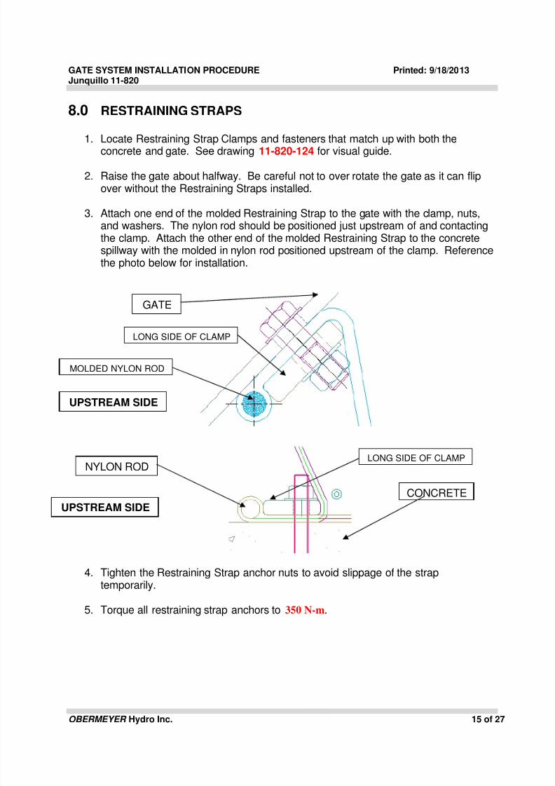
1. Locate Restraining Strap Clamps and fasteners that match up with both theconcrete and gate. See drawing 11-820-124 for visual guide.
2. Raise the gate about halfway. Be careful not to over rotate the gate as it can flipover without the Restraining Straps installed.
3. Attach one end of the molded Restraining Strap to the gate with the clamp, nuts,and washers. The nylon rod should be positioned just upstream of and contactingthe clamp. Attach the other end of the molded Restraining Strap to the concretespillway with the molded in nylon rod positioned upstream of the clamp. Referencethe photo below for installation.
4. Tighten the Restraining Strap anchor nuts to avoid slippage of the straptemporarily.
5. Torque all restraining strap anchors to 350 N-m.
GATE
CONCRETE
UPSTREAM SIDE
UPSTREAM SIDE
LONG SIDE OF CLAMP
LONG SIDE OF CLAMPNYLON ROD
MOLDED NYLON ROD
8/9/2019 11-820 Installation Procedure
http://slidepdf.com/reader/full/11-820-installation-procedure 16/27
GATE SYSTEM INSTALLATION PROCEDURE Printed: 9/18/2013Junquillo 11-820
OBERMEYER Hydro Inc. 16 of 27
9.0 LEAK TEST GATE SYSTEM
***ONCE THE GATE IS INSTALLED COMPLETELY THESYSTEM MUST BE CHECKED FOR LEAKS. ***
* TESTING
-THE GATES SHOULD BE RAISED TO AN
INTERMEDIATE LEVEL.- THE ABUTMENT SEALS SHOULD BE MARKED AT THEABUTMENT WALLS AND CHECKED AFTER 24 HRS.-THIS LEVEL WILL BE SUBJECT TO FLUCTUATIONSBASED ON AMBIENT TEMPERATURE
*TESTING ALTERNATE (PREFERRED)
- FLOOD THE UPSTREAM SIDE OF THE GATE ENOUGHTO SUBMERGE THE MAIN ANCHOR CLAMPS.- FLOOD THE DOWNSTREAM SIDE OF THE GATESJUST ENOUGH TO COVER THE SPILLWAY BY 3-4INCHES OF WATER.- INFLATE THE GATE TO 5 PSI FOR APROXIMATELY 12HOURS- LOOK FOR VISIBLE SIGNS OF AIR LEAKAGE ALONGTHE BLADDERS AND CLAMPS.- RE-TORQUE AS NECESSARY
8/9/2019 11-820 Installation Procedure
http://slidepdf.com/reader/full/11-820-installation-procedure 17/27
GATE SYSTEM INSTALLATION PROCEDURE Printed: 9/18/2013Junquillo 11-820
OBERMEYER Hydro Inc. 17 of 27
10.0 LOCATING AND ANCHORING AIR SUPPLY, ACC and PLC
1. Place Air Control Cabinet (ACC) into its final position.
2. Using a marker, mark the holes on the wall or floor accordingly. Move thecabinet away from the marked holes.
3. Using the concrete drill, bore holes which match the manufacturersrecommended depth and diameter for the stainless steel wedge type anchors.Install the wedge type anchors.
4. Place the cabinet in the appropriate position. Tighten anchors until the cabinetis firmly anchored.
5. Connect the pipes to appropriate ports per the project drawings.
6. Repeat the process for the air compressor equipment, blowers, and ProgramLogic Controller (PLC).
11.0 ELECTRICAL
1. Contractor to supply and install control wiring between the ACC and PLC perapplicable building codes.
2. All electrical conduit shall be as specified in the drawing.
3. Contractor to supply and install power supply conduit and wiring between thecircuit breaker and compressor & blower motors per project drawings.
4. Contractor to supply and install sensor cabling between external terminationboxes and the PLC cabinet per project drawings.
5. Contractor to procure circuit breaker panel per project drawings and install inaccordance with appropriate building codes.
12.0 FIELD TESTING
1. An OHI field representative should be on site for system start up.
2. The air supply pipes shall be tested prior to covering with concrete, backfilled,or otherwise concealed. The air piping between the gate and the air controlcabinet shall be tested by pressurizing to 50psi for 24-hours. Pressurereadings and ambient air temperature shall be recorded at six different timesduring the test.

8/9/2019 11-820 Installation Procedure
http://slidepdf.com/reader/full/11-820-installation-procedure 18/27
GATE SYSTEM INSTALLATION PROCEDURE Printed: 9/18/2013Junquillo 11-820
OBERMEYER Hydro Inc. 18 of 27
3. A wet test of the air lines may be performed with a leak detection solution at 50psi in place of the 24 hour timed test.
4. Any joints or fittings exhibiting leakage during this time shall be repaired orreplaced.
5. The air piping between the air control cabinet and high pressure equipmentshall be tested by pressurizing to 150 psi for 24-hours. Pressure readings andambient air temperature shall be recorded at six different times during the test.Any joints or fittings exhibiting leakage during this time shall be repaired orreplaced.
6. After installation of the gate system, before removing the cofferdam the spillway
gates shall be fully raised and lowered three (3) times using a portable airsupply. The gate shall operate smoothly with no binding.
7. Do not inflate air bladder past the operating pressure found in the hydrauliccalculations.

8/9/2019 11-820 Installation Procedure
http://slidepdf.com/reader/full/11-820-installation-procedure 19/27
GATE SYSTEM INSTALLATION PROCEDURE Printed: 9/18/2013Junquillo 11-820
OBERMEYER Hydro Inc. 19 of 27
13.0 TORQUES AND TOOLS
a. Torque Values: The following Torque settings will be used for the project:
Main Anchor Bolt (Ø1-3/4”- 5 UNC x 1000mm): 1400 N-m
Gate Panel Flange Bolt (M24 x 75mm): 270 N-m
Restraining Strap Anchor (M30 x 460mm): 350 N-m
Restraining Strap Bolt (M30 c 100mm”): 270 N-m
Hinge Flap Retainers (M30): 270 N-m
Abutment/J-Bulb Seal Retainers (M16): 100 N-m
Nappe Breaker Bolt (M12 x 40mm): 50 N-m
b. Required Tools
Controls & Compressor (tools)• Adjustable wrenches• Pipe wrenches• Screw driver• Fine point permanent marker• 8 – Stainless steel M12 diameter x 150mm length wedge anchors• Concrete drill for M12 diameter wedge anchor• Lifting/moving apparatus
Gate System Installation (tools)
• Wrench and socket for Main Anchor Bolts. Air impact wrench incombination with manual torque wrench is satisfactory. A hydraulictorque wrench is more convenient if available.
• Sockets and ratchet wrenches for seal retainer and hinge flap nuts.• Utility knives for cutting rubber• 3lb hammer and (7/8”=22mm) rubber punches for Abutment/J-Bulb seals• Anti-seize compound sufficient for all studs, washers, and nuts.• 32 tubes of 100% silicone or aquarium grade caulk and 2 caulk guns.• Rags for cleaning up silicone messes.• Abrasive cutoff saw and motorized reciprocating saw (e.g. “Sawzall”) or
chain saw for trimming Hinge Flaps to length.
• Air bladder lifting clamps (designed by OHI).• Hand held angle grinder.• Lifting shackles to fit Gate Panel lifting holes, spreader bar for bladders.• 2 Pry bars approximately 1M long.• Electric drills.• Pipe joint compound and Teflon tape for air fittings.• Pipe wrenches for air fittings.• Pliers• Shackles to fit crane hook to L shaped clamp casting lifting bracket.• Thread File.• Thread cutting dies to fit all smaller threads for repair if required.
8/9/2019 11-820 Installation Procedure
http://slidepdf.com/reader/full/11-820-installation-procedure 20/27
GATE SYSTEM INSTALLATION PROCEDURE Printed: 9/18/2013Junquillo 11-820
OBERMEYER Hydro Inc. 20 of 27
14.0 COMMON CONSTRUCTION ERRORS AND TIPS
c. Common Construction Errors
• Abutment Plate to Abutment Plate Spacing Not Correct –This is a very commonmistake. If the span width is too great the gate system may not seal properly.If the span width is too short, the gates may not fit. There could also be permit
issues related to insufficient waterway width.
• Anchor Bolt Assemblies Not Secured for Concrete Placement - Anchor boltassemblies can move from pressure of concrete causing shifting so they are nolonger perpendicular to abutment wall (which creates interference with how thegate swings up and down), or to drift left or right (which will cause the clampcastings and bladders to not fit.
• Projection of Anchor Bolts - Anchor bolt projection not enough (makinginstallation of clamps difficult or impossible) or projection is too much (reducingembedment length and reducing pull out strength.
• Anchor Bolt Spacing – Anchors are not spaced properly because hole patternnot used properly or other reason. This will cause clamp castings to not fit.
• Abutment Walls Not Plumb – When abutment walls are not cast plumb, the OHIsupplied Abutment Plates (either stainless steel or UHMW plastic) will not beplumb. This will create a variable width gap between the Abutment Wall andgate which could lead to gate interference and water leakage.
• Abutment Walls Bowed – Insufficient form bracing can cause the AbutmentWalls to bow out. If this exceeds 12mm the OHI Abutment Seals will not workproperly. This may lead to the gate system not sealing as it should. Steel formwork is recommended.
•
Concrete Surface not Level – If top of concrete elevation varies by more than12mm over a span of 1.5M, or more that 50mm over the width of the waterway,the clamp castings will not seat as designed possibly leading to leak pathsbetween the Gate Panels (that can not be sealed) or a total gate system crestheight that varies, which reduces overall storage capacity.
• Spillway Elevation – variations in elevation across the spillway will result ineven larger variations in the top-of-gate elevation. This is because low sectionsof the gate are further lowered by greater water pressure. A 50mm variation inspillway crest elevation result in a 100mm top of gate elevation. Keep the topof concrete crest LEVEL.
Remember !!!
Mistakes cause rework and delays Lost Contractor Profit
Mistakes create loss of gate performance Lost Owner Revenue

8/9/2019 11-820 Installation Procedure
http://slidepdf.com/reader/full/11-820-installation-procedure 21/27
GATE SYSTEM INSTALLATION PROCEDURE Printed: 9/18/2013Junquillo 11-820
OBERMEYER Hydro Inc. 21 of 27
d. Tips for a Successful Project
ANCHOR BOLTS• Check that anchor bolt templates match drawing• Double check bolt to bolt spacing on assemblies• Ensure bolt to bolt spacing is correct between anchor bolt assemblies• Double check concrete pour depth with design bolt projection• Double check that all anchor bolts are within 3mm of alignment.• Form a 3’ 4’ 5’ triangle (to create 90 degrees) and ensure the centerline of
anchor bolts is exactly perpendicular to both abutment walls
CONCRETE LEVEL ON ANCHOR BOLT CENTERLINE• If stainless steel heel and pivot angle embeds are supplied, pre-level and use
as screed line surfaces• If no other embeds are provided (except anchor bolts) pre-survey top of
concrete lines and double check.
ABUTMENT WALLS• Check that abutment wall forms are plumb• Check design of abutment wall formwork. Is lateral support adequate? Are
forms properly braced and tied off?• Are abutment wall perpendicular to anchor bolts.
CONCRETE QUALITY•
Concrete should be trowel finish quality under all rubber surfaces• Concrete should be trowel finish quality 600mm in both directions of the anchor
bolt line• All air assembly, instrument junction box and restraining strap block outs should
have a 25mm chamfer cast in place. Chamfer must be ground after pour to aradius.
EPOXY GROUTING OF ANCHOR BOLTS• Use proper drill template• Ensure all holes are properly washed and dried prior to application of epoxy.• Store epoxy per supplier requirements•
Do not exceed manufacturers recommended hole diameter. An excessivelylarge hole may result in excessive epoxy shrinkage, failure of the epoxy bond tothe concrete, and anchor bolt pullout.
BLOCK OUTS AND PIPING• Cap all air lines prior to concrete pours. Make efforts to keep normal
construction debris and wildlife (fish, rodents, insects, snakes, crustaceans) outof the airlines.
• Double check location of block-outs. Are dimensions called out to the centerline or the edge of the block out? The number of air block outs matches thenumber of bladders.

8/9/2019 11-820 Installation Procedure
http://slidepdf.com/reader/full/11-820-installation-procedure 22/27
GATE SYSTEM INSTALLATION PROCEDURE Printed: 9/18/2013Junquillo 11-820
OBERMEYER Hydro Inc. 22 of 27
d e f
c
b
a
15.0 CHECK LISTS
e. Abutment Plate Check List
A. Abutment face to Abutment face dimension
a) At base near anchors
b) At tip of gate in up position
c) At tip of gate in down position.
B. Abutment Plate Plumb (difference between top and bottom of each section)
d.1) Left Abutment at anchors bolt plane
d.2) Right Abutment at anchors bolt plane
e.1) Left Abutment at middle of lowered gate
e.2) Right Abutment at middle of lowered gate
f.1) Left Abutment at lowered gate tip plane
f.2) Right Abutment at lowered gate tip plane
TOLERANCE +/- 6mm
All three measurements should be within 6mm of above dimension
PER DRAWING (mm)
TOLERANCE +/- 6mm
Total out of plumb measurement must be within 6mm

8/9/2019 11-820 Installation Procedure
http://slidepdf.com/reader/full/11-820-installation-procedure 23/27
GATE SYSTEM INSTALLATION PROCEDURE Printed: 9/18/2013Junquillo 11-820
OBERMEYER Hydro Inc. 23 of 27
g
h
i
Abutment Plate edge view
2” stand offat edge of
plate
Measured Offset
Sketch shows section looking at top or side of abutment
plate – using a taught string line between the two stand
off points.
2” stand offat edge of
plate
C. Abutment Plate Horizontal Flatness (deflection across plate)
g.1) Left Abutment vertical at anchor bolts
g.2) Right Abutment vertical at anchor bolts
h.1) Left Abutment vertical middle
h.2) Right Abutment vertical middle
i.1) Left Abutment vertical gate up
i.2) Right Abutment vertical gate up
TOLERANCE +/- 6mm
No point on each horizontal line can be more than 6mm out of plane

8/9/2019 11-820 Installation Procedure
http://slidepdf.com/reader/full/11-820-installation-procedure 24/27
GATE SYSTEM INSTALLATION PROCEDURE Printed: 9/18/2013Junquillo 11-820
OBERMEYER Hydro Inc. 24 of 27
5 ftb(? ft)
3 ftA
B
C Calculate Angle A by laying out a 3-4-5 triangle,
then measure what the 4’ leg actually is.
Angle A = arccos (16 – b2) / (6b)
If b = 4’, the anchor bolts are perpendicular to
the abutment wall.
Actual AngleLeft Abutment Actual Angle
Right Abutment
D. Squareness of Anchor Bolt Alignment to Abutment Plate
j.1) Angle between Left Abutment and Centerline of anchor bolts
j.2) Angle between Left Abutment and Centerline of anchor bolts
TOLERANCE +/- 0.1 degree

8/9/2019 11-820 Installation Procedure
http://slidepdf.com/reader/full/11-820-installation-procedure 25/27
GATE SYSTEM INSTALLATION PROCEDURE Printed: 9/18/2013Junquillo 11-820
OBERMEYER Hydro Inc. 25 of 27
Centerline of anchor bolts – drawn with taught
string line between two outer most anchor bolts
Distance of center of anchor
bolt most out of alignment
f. Main Anchor Bolt Check List
A. Anchor Bolt Spacing
k.1) Distance between Right Abutment Plate Face to Center of nearest anchor bolt
k.2) Distance between left Abutment Plate Face to Center of nearest anchor bolt
B. Straightness of Anchor Bolt Alignment
l) Distance between center line of anchor bolts and bolt most out of alignment
Left Abutment Plate
Right Abutment Plate
N1 = distance from face of right
abutment wall to centerline of firstmain anchor bolt
N2 = distance from face of left
abutment wall to centerline of firstmain anchor bolt

8/9/2019 11-820 Installation Procedure
http://slidepdf.com/reader/full/11-820-installation-procedure 26/27
GATE SYSTEM INSTALLATION PROCEDURE Printed: 9/18/2013Junquillo 11-820
OBERMEYER Hydro Inc. 26 of 27
g. Concrete Check List
Elevation (top of concrete & anchors) Across the Spillway
m.1) Difference between highest and lowest elevations across the spillway crest (measured near
the main anchor bolts (mm)
n.2) Difference between highest and lowest elevations of main anchors ______________(mm)_

8/9/2019 11-820 Installation Procedure
http://slidepdf.com/reader/full/11-820-installation-procedure 27/27
GATE SYSTEM INSTALLATION PROCEDURE Printed: 9/18/2013Junquillo 11-820
Positioning of Block outs
o.1) Distance between Left abutment wall and centerline of first air assembly block out __
o.2) Distance between CL first left air block out and CL of second air block out __
p.1) Distance between Right abutment wall and centerline of first air assembly block out __
p.2) Distance between CL first right air block out and CL of second air block out __
q.1) Distance between Left abutment was and centerline of first restraining strap block out _____
q.2) Distance between CL first left restraining strap block out and CL of second restraining strap
block out _______
r.1) Distance between Right abutment was and centerline of first restraining strap block out ____
r.2) Distance between CL first right restraining strap block out and CL of second restraining strap
block out _______
Distance between Left
abutment wall and
centerline of first air
assembly block out
Distance between
centerline of first air
block out and center of
second air block out