Embed Size (px)
Citation preview
11-818 Precision pressure regulator
01/16en 8.440.200.01
Our policy is one of continued research and development. We therefore reserve the right to amend, without notice, the specifications given in this document. (1997 - 8148d) © 2015 Norgren Inc.
Technical features
> Port size: G1/4
> Precision instruments with integral pilot to ensure very close pressure control in a compact form
> Panel mounting facility
Technical data, standard modelsSymbol Port
sizePressure range(bar)
Accuracy(bar) *1)
Relieving Gauge port Tamper proof adjusting screw
Weight (kg)
Model
G1/4 0,02 ... 0,5 (low) 0,01 Standard — — 0,64 11-818-999
G1/4 0,02 ... 0,5 (low) 0,01 Standard — Standard 0,64 11-818-998
G1/4 0,07 ... 4 (standard) 0,03 Standard — — 0,64 11-818-100
G1/4 0,07 ... 4 (standard) 0,03 Standard — Standard 0,64 11-818-101
G1/4 0,4 ... 10 (high) 0,05 Standard — — 0,64 11-818-110
G1/4 0,02 ... 0,5 (low) 0,01 Standard R1/4 — 0,64 11-818-987
G1/4 0,07 ... 4 (standard) 0,03 Standard R1/4 — 0,64 11-818-993
G1/4 0,4 ... 10 (high) 0,05 Standard R1/4 — 0,64 11-818-991
*1) Typical mid-range variance from set pressure with 7 bar inlet at 2 dm3/sNote: 11-818 is not a constant bleed device, when being used under flow conditions no air is consumed. Air bleed is only effective under zero flow conditions as in a dead end application.
Note: Not recommended for dead-end applications
Medium:Compressed air Note: 5 μm prefiltration and oil-free are required!Maximum inlet pressure: 8 bar (116 psi) (low) 10 bar (145 psi) (standard) 14 bar (203 psi) (high)Flow:See diagrams on page 2
Relieving:StandardPressure range:0,07 ... 4 bar (1 ... 58 psi) (standard) 0,02 ... 0,5 bar (0,2 ... 7 psi) (low) 0,4 ... 10 bar (5,8 ... 145 psi) (high)Port size:G1/4Gauge port:See table below
Ambient/Media temperature:0 ... +70°C (+32° ... +158°F) Version with gauge: 0 ... +65°C (+32° ... +149°F) Air supply must be dry enough to avoid ice formation at temperatures below +2°C (+35°F).
Materials:Body & bonnet: Zinc alloy Adjusting knob: Acetal resin Elastomers: NBR

Aus
gan
gsd
ruck
0 2 4 6 8 10 12
4,2
4,1
4,0
2,1
2,0
6,2
6,1
10,4
10,3
bar
bar0 1 2 3 4 5
4,2
4,1
4,0
2,1
2,0
6,2
6,1
10,3510,30
10,20
bar
dm3/s
0 1 2 3 4 5
0,70
0,65
0,60
0,35
0,30
2,10
2,05
2,00
4,15
4,10
bar
dm3/sA
usg
ang
sdru
ck0 2 4 6 8 10
0,70
0,65
0,60
0,35
0,30
2,10
2,05
2,00
4,15
4,10
bar
bar
11-818 Precision pressure regulator
Our policy is one of continued research and development. We therefore reserve the right to amend, without notice, the specifications given in this document. (1997 - 8148d) © 2015 Norgren Inc.en 8.440.200.02
01/16
Standard pressure version: Inlet pressure 7 bar (100 psi); pressure range 0,1 ... 4,1 bar (1 ... 60 psi)
High pressure version: Inlet pressure 14 bar (200 psi); pressure range 0,2 ... 10,35 bar (3 ... 150 psi)
Flow characteristics Regulating characteristics
Out
let
pre
ssur
eO
utle
t p
ress
ure
Out
let
pre
ssur
eO
utle
t p
ress
ure
Air flow
Air flow
Air flow
Air flow
Service kitsService kits
2787-96 (low pressure)
2787-98 (standard pressure)
2787-97 (high pressure)
AccessoriesGaugeØ 40 mm, Port size R1/8
Concentric reducing adaptors for gauge ports
0 ... 1,6 bar: 18-013-991 R1/4-G1/8 150232818
0 ... 4 bar: 18-013-990 R3/8-G1/8 150233818
0 ... 10 bar: 18-013-989 R1/2-G1/8 150234818
54
43
2715
63
127
54
2
1
1217
Our policy is one of continued research and development. We therefore reserve the right to amend, without notice, the specifications given in this document. (1997 - 8148d) © 2015 Norgren Inc.
11-818 Precision pressure regulator
en 8.440.200.0301/16
Warning
These products are intended for use in industrial compressed air systems only. Do not use these products where pressures and temperatures can exceed those listed under »Technical features/data«. Before using these products with fluids other than those specified, for non-industrial applications, life-support systems or other applications not within published specifications, consult IMI Precision Engineering, Norgren Inc.
Through misuse, age, or malfunction, components used in fluid power systems can fail in various modes. The system designer is warned to consider the failure modes of all component parts used in fluid power systems and to provide adequate safeguards to prevent personal injury or damage to equipment in the event of such failure. System designers must provide a warning to end users in the system instructional manual if protection against a failure mode cannot be adequately provided. System designers and end users are cautioned to review specific warnings found in instruction sheets packed and shipped with these products.
EN - Englisch
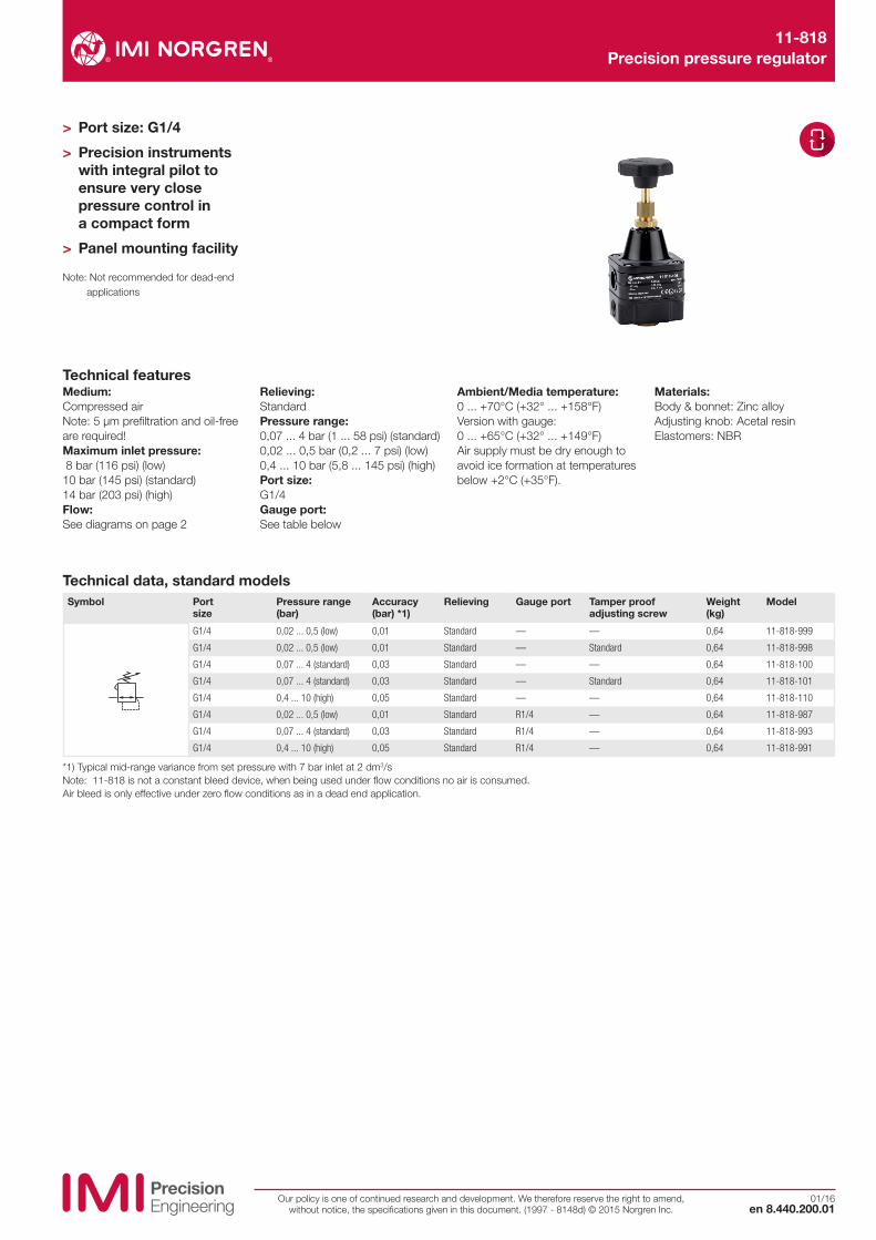
Dimensions
1 Gauge port R1/4 for models 11-818-979, 11-818-993 and 11-818-991 only
2 Panel mounting hole > ø 12 mm wall thickness < 6 mm
Dimensions in mm Projection/First angle

R27-200 Series Precision pressure regulator, manually actuated
3/15en 8.450.200.01
Our policy is one of continued research and development. We therefore reserve the right to amend, without notice, the specifications given in this document. (2013 - 8125b) © 2015 Norgren Ltd.
Medium:Oil free, dry air filtered to 25 µmNote: for use with gases other than compressed air please consult NORGRENOperation:Handwheel 2,5 ... 3 turns
Inlet pressure:At least 0,2 bar ( 3 psi) above max required output pressure, up to a maximum of 10 bar (145 psi)Air and gauge ports:G1/4 or 1/4 NPT
Flow capacity:Up to 500 l/minHysteresis & repeatability:Typically < 0,05% at mid rangeAmbient/Media temperature:-20 ... +70°C (-4 ... +158°F)Air supply must be dry enough to avoid ice formation at temperatures below +2°C (+35 °F)
Materials:Body: Passivated zinc, epoxy painted Springs: Stainless steel Elastomers: NBR
Technical features
> Port size: 1/4” (ISO G, NPT)
> Versatile design for varied applications
> High-precision manual pressure regulator
> Highly sensitive and accurate
> Perfect for dead-end applications
> Excellent long term stability
> High forward and relief flow capability
> Low air consumption
Technical data, standard modelSymbol Port
sizePressure range(bar)
Air consumption(l/min)
Regulation accuracy *1) (%)
Weight(kg)
Model
G1/4 0,14 ... 2,0 Typically < 2 0,1 0,78 R27-200-RNCG
G1/4 0,14 ... 4,0 Typically < 2 0,05 0,78 R27-200-RNFG
G1/4 0,14 ... 8,0 Typically < 2 0,02 0,78 R27-200-RNLG
*1) % output change for 1 bar supply pressure change at mid-range output “ Other options available include captured bleed, natural gas, gearbox, yoke mount, weatherproof, alternative pneumatic connections and low pressure versions. For options not shown and any specific requirements please contact the Norgren technical department via www.norgren.com/watsonsmith”
R27-200-RN˙˙Option selectorPressure range Substitute
0,14 ... 2,0 bar (2 ... 29 psi) C
0,14 ... 4,0 bar (2 ... 58 psi) F
0,14 ... 8,0 bar (2 ... 116 psi) L
Threads Substitute
NPT R
ISO G parallel G

R27-200 Series Precision pressure regulator, manually actuated
Our policy is one of continued research and development. We therefore reserve the right to amend, without notice, the specifications given in this document. (2013 - 8125b) © 2015 Norgren Ltd.en 8.450.200.02
3/15
Flow characteristics
Dimensions
Forward flow (supply pressure 7 bar) Relief flow (supply pressure 7 bar)
Flow Flow
Out
let
pre
ssur
e
Out
let
pre
ssur
e0 200 400 600 l/min
8
6
4
2
0
bar
400 300 200 100 0 l/min
8
6
4
2
0
bar
1 Inlet port G1/4 or 1/4 NPT2 Outlet port G1/4 or 1/4 NPT3 Gauge port G1/4 or 1/4 NPT4 Tension nut5 Mounting nut (Ø 11,5 required
for panel mounting)6 Exhaust, do not obstruct!7 Bleed port8 Mounting holes (mount with M4 x 8
mm self tap screws)
ø 35
< 44
44
69
54
14
1/4”1/4” 27
2~
415
18 5
8
66
7
33 21
OU
T
IN
IN OUT
WarningThese products are intended for use in industrial compressed air systems only. Do not use these products where pressures and temperatures can exceed those listed under »Technical features/data«.Before using these products with fluids other than those specified, for non-industrial applications, life-support systems or other applications not within published specifications, consult IMI NORGREN.
Through misuse, age, or malfunction, components used in fluid power systems can fail in various modes.
The system designer is warned to consider the failure modes of all component parts used in fluid power systems and to provide adequate safeguards to prevent personal injury or damage to equipment in the event of such failure.System designers must provide a warning to end users in the system instructional manual if protection against a failure mode cannot be adequately provided.System designers and end users are cautioned to review specificwarnings found in instruction sheets packed and shipped with these products.
Dimensions in mm Projection/First angle

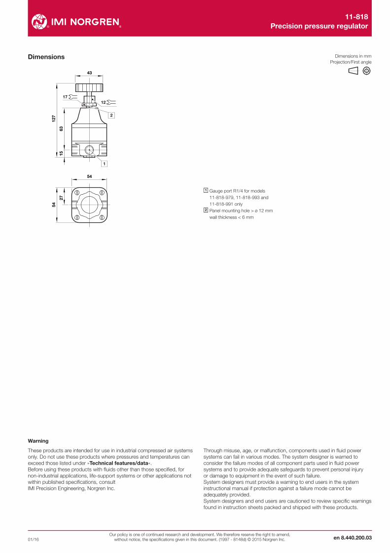
R38 Precision regulator (stainless steel)
3/15en 8.530.220.01
Our policy is one of continued research and development. We therefore reserve the right to amend, without notice, the specifications given in this document. (1997 - 8165d) © 2015 Norgren Inc.
Medium:Compressed air onlyMaximum inlet pressure:31 bar (449 psi)
Outlet pressure range:0,04 ... 2 bar ( 0,5 ... 29 psi), 0,07 ... 4 bar (1 ... 58 psi), 0,25 ... 7 bar ( 3,6 ... 101 psi), 0,4 ...10 bar (5 ... 145 psi)
Port sizes:1/4 PTF 1/4 PTF (gauge), 1/8 PTF (relief)Ambient/Media temperature:-40 ... +80°C (-40 ... +176 °F)Air supply must be dry enough to avoid ice formation at temperatures below +2°C (+35 °F).
Materials:Body, bowl, bonnet & adjusting screw: stainless steel Elastomers: Synthetic rubber
Technical features
> Port size: 1/4 PTF
> Designed for use in corrosive environment
> Metallic parts meet NACE* Standard MR-01-75
> Applications include marine environment, oil and gas production, chemical and food processing, medical analysis
> Model for precision regulation and high flow
* National Association of Corrosion Engineers – recognised oil-field recommendation for resistance to sulphide stress cracking common in well-head and other corrosive environments
Technical data, standard model, relievingSymbol Port
sizeOutlet pressure (bar)
Flow * (dm3/s)
Weight (kg)
Model
1/4 PTF 0,04 ... 2 8 1,1 R38-240-RNCA
1/4 PTF 0,07 ... 4 8 1,1 R38-240-RNFA
* Typical flow with 7 bar inlet pressure, 1 bar set pressure and 0,05 bar drop from set.
R38-24˙-˙N˙AOption selectorMounting Substitute
None 0
Neck mounting bracket 1
Panel nut 2
Diaphragm Substitute
Relieving R
Non relieving N
Outlet pressure adjustment ranges (bar)*
Substitute
0,04 ... 2 C
0,07 ... 4 F
0,25 ... 7 K
0,4 ... 10 M
* Outlet pressure can be adjusted to pressures in excess of, and less than, those specified. Do not use these units to control pressures outside of the specified ranges.
R38 Precision regulator (stainless steel)
Our policy is one of continued research and development. We therefore reserve the right to amend, without notice, the specifications given in this document. (1997 - 8165d) © 2015 Norgren Inc.en 8.530.220.02
3/15
64
64 75
118
5328
42
1
20 ...
6
ø 41
13
Flow rate
Out
let
pre
ssur
e
Inlet pressure: 7 bar, port size: 1/4 PTF
Flow characteristics
AccessoriesPanel nut Neck mounting
bracketNeck mounting bracket
Gauge * Plastic adjusting knob
5988-02 5989-02 18-001-973 (includes panel nut) 18-013-913 (0 ... 6 bar) 74630-04
18-013-909 (0 ... 10 bar)
* Stainless steel items not strictly to NACE standard MR-01-75.
Spares kitValve assembly and diaphragm
Description Model2 bar relieving R38-100R
4 and 7 bar relieving R38-101R
10 bar relieving R38-102R
2 bar non-relieving R38-100NR
4 and 7 bar non-relieving R38-101NR
10 bar non-relieving R38-102NR
3
2
1
10 2 3 4 5 6 7 8 9 10 11 (dm3/s)
(bar)
Dimensions Neck mounting bracket
1 1/4 PTF Gauge port2 1/8 PTF Relief port
WarningThese products are intended for use in industrial compressed air systems only. Do not use these products where pressures and temperatures can exceed those listed under »Technical features/data«.Before using these products with fluids other than those specified, for non-industrial applications, life-support systems or other applications not within published specifications, consult IMI NORGREN.
Through misuse, age, or malfunction, components used in fluid power systems can fail in various modes.
The system designer is warned to consider the failure modes of all component parts used in fluid power systems and to provide adequate safeguards to prevent personal injury or damage to equipment in the event of such failure.System designers must provide a warning to end users in the system instructional manual if protection against a failure mode cannot be adequately provided.System designers and end users are cautioned to review specificwarnings found in instruction sheets packed and shipped with these products.
Dimensions in mm Projection/First angle
75
54
6,5
651,
5
35
38
41
8,5
25