Embed Size (px)
DESCRIPTION
obu
Citation preview

ALCATEL * ALSTOM * ANSALDO SIGNAL * BOMBARDIER * INVENSYS RAIL * SIEMENS
ERTMS/ETCS – Class 1
Euroradio FIS
REF : SUBSET-037 ISSUE : 2.3.0 DATE: 14-Oct-2005
Company Technical Approval Management approval ALCATEL
ALSTOM
ANSALDO SIGNAL
BOMBARDIER
INVENSYS RAIL
SIEMENS
© This document is the property of ALCATEL * ALSTOM * ANSALDO SIGNAL * BOMBARDIER * INVENSYS RAIL * SIEMENS
Subset-037 Version 2.3.0
EURORADIO FIS Page 1/100

ALCATEL * ALSTOM * ANSALDO SIGNAL * BOMBARDIER * INVENSYS RAIL * SIEMENS
1. MODIFICATION HISTORY Issue Number
Date Section Number Modification / Description Author
2.0.0 30-March- 2000
Final issue to ECSAG U.D. (ed)
2.1.0 23-November-2001
All Revision LK
2.1.7 Version with revision marks LK
2.2.0 Final issue after revision LK
2.2.1 3.4, 5.2, 5.3, 7.1.2, 7.2.2, 7.2.4, 7.2.5, 7.3.2, 8.2.3, 8.2.4, 8.3.1, Annex A, B.1, C.1
Review comments of Unisig super group inserted
LK
2.2.1+ 7.2.5.3.6, 7.2.5.3.7 State table updated (state DATA, event DT SaPDU -> splitting in to Conditions Pre 5 and Pre 6; state AR SaPDU, event AR SaPDU -> DI SaPDU added)
TS
2.2.1.++ 7.3.2.2.1 Table 23 Bit numbering changed
TS
2.2.2r 3.4.1.1, 7.2.5.3.6 Editorial changes LK
2.2.2 - Clean version LK
2.2.3 3., 3.1.1.5, 3.1.16, 3.3, 3.4.1, 7.2.2.2.1.4, 7.2.5.3.7, 8.2.3.1.2, 8.3.1.14
Review comments of GSM-R users group inserted, Clarifications, references updated
LK
2.2.4 - Clean version LK
2.2.5 - Formal release LK
2.2.5.revA 3.4, 5.2, 5.7, 7.3.3, 8.2.2, 8.2.4, 8.2.5, 8.3.1
Proposed changes according to LOP v 020
LK
2.2.5.revB 3.4, 5.2, 5.7, 7.3.3, 8.2.2, 8.2.3, 8.2.4, 8.2.5, 8.3.1, B.1, B.5
Changes of Neu-Ulm meeting
TS+LK
© This document is the property of ALCATEL * ALSTOM * ANSALDO SIGNAL * BOMBARDIER * INVENSYS RAIL * SIEMENS
Subset-037 Version 2.3.0
EURORADIO FIS Page 2/100

ALCATEL * ALSTOM * ANSALDO SIGNAL * BOMBARDIER * INVENSYS RAIL * SIEMENS
2.2.5.revC 5.2.1.7, 7.3.3.5.4, 8.2.2.6, 8.2.2.9, 8.2.3.2.3, 8.3.1.1, 8.3.2.2.1, 8.3.3.1.2, B.1.1.1.9
Changes of Berlin meeting LK
2.2.5.revD 3.4.1, 8.2.5, 8.3.1, 8.3.3, Annex A
Changes of Edinburgh meeting
TS+LK
2.2.5.revE 3.4, 4.1.1.1, 7.2.2.2.2, 7.2.4.2, 7.3.2, 8.2.2, 8.2.4, Annex D, Annex E
Changes of Stockholm meeting and email discussion
LK
2.2.5.revF 3.3, 3.4, 7.2.2, 7.2.4, 7.3.2, 8.2.2, 8.2.5, 8.3.1, AnnexD, AnnexE
Changes of Paris meeting and email discussion
WM+LK
2.2.5.revG 4.1.1.10, 5.71.4, 7.3.3.5.6, 8.2.3.2.5, 8.2.5, 8.2.7, E.2
Changes of Zürich meeting PL+LK
2.3.0 AnnexE.1, Tables 31, 34, 35
Formal release JH
© This document is the property of ALCATEL * ALSTOM * ANSALDO SIGNAL * BOMBARDIER * INVENSYS RAIL * SIEMENS
Subset-037 Version 2.3.0
EURORADIO FIS Page 3/100

ALCATEL * ALSTOM * ANSALDO SIGNAL * BOMBARDIER * INVENSYS RAIL * SIEMENS
2. TABLE OF CONTENTS 1. MODIFICATION HISTORY ................................................................................................................. 2 2. TABLE OF CONTENTS ..................................................................................................................... 4 3. GENERAL ASPECTS ........................................................................................................................ 6
3.1 Scope.................................................................................................................................. 6 3.2 Acronyms and abbreviations .............................................................................................. 6 3.3 Definitions ........................................................................................................................... 9 3.4 References ....................................................................................................................... 11
3.4.1 Normative References............................................................................................... 11 3.4.2 Informative References ............................................................................................. 12
4. REFERENCE ARCHITECTURE ......................................................................................................... 13 5. INTERFACE TO SAFE SERVICES ..................................................................................................... 16
5.1 General ............................................................................................................................. 16 5.2 Service primitives for safe connection set-up ................................................................... 16 5.3 Service primitives for safe data transfer ........................................................................... 18 5.4 Service primitives for connection release ......................................................................... 19 5.5 Service primitives for error reporting................................................................................. 20 5.6 Service primitives for high priority data............................................................................. 21 5.7 Service primitives for network registration ........................................................................ 22
6. INTERFACE TO THE MOBILE NETWORK ........................................................................................... 24 7. SAFE FUNCTIONAL MODULE ......................................................................................................... 25
7.1 Service definition .............................................................................................................. 25 7.1.2 Model of the safe services......................................................................................... 25 7.1.3 Safe connection set-up.............................................................................................. 26 7.1.4 Safe data transfer ...................................................................................................... 26 7.1.5 Release of safe connection ....................................................................................... 27 7.1.6 Error reporting ........................................................................................................... 27 7.1.7 Service for high priority data...................................................................................... 27
7.2 Safety protocol.................................................................................................................. 27 7.2.1 Introduction................................................................................................................ 27 7.2.2 Functions of the safety layer...................................................................................... 28 7.2.3 Time sequences ........................................................................................................ 35 7.2.4 Structure and encoding of safety PDUs .................................................................... 39 7.2.5 State table ................................................................................................................. 43
7.3 Safety Protocol Management ........................................................................................... 49 7.3.1 Functions of the Safety Protocol Management.......................................................... 49
© This document is the property of ALCATEL * ALSTOM * ANSALDO SIGNAL * BOMBARDIER * INVENSYS RAIL * SIEMENS
Subset-037 Version 2.3.0
EURORADIO FIS Page 4/100

ALCATEL * ALSTOM * ANSALDO SIGNAL * BOMBARDIER * INVENSYS RAIL * SIEMENS
7.3.2 Configuration Management ....................................................................................... 49 7.3.3 Supervision and Diagnostics ..................................................................................... 50
8. COMMUNICATION FUNCTIONAL MODULE........................................................................................ 55 8.1 Service definition .............................................................................................................. 55
8.1.1 Model of communication services ............................................................................. 55 8.1.2 Connection establishment ......................................................................................... 55 8.1.3 Data transfer.............................................................................................................. 56 8.1.4 Connection release.................................................................................................... 57 8.1.5 High priority data ....................................................................................................... 57 8.1.6 Quality of Service ...................................................................................................... 57
8.2 Communication protocols ................................................................................................. 58 8.2.1 Introduction................................................................................................................ 58 8.2.2 Data Link Layer ......................................................................................................... 58 8.2.3 Network Layer ........................................................................................................... 60 8.2.4 Transport Layer ......................................................................................................... 61 8.2.5 Applicability conditions of X.224 ................................................................................ 66 8.2.6 Time sequences ........................................................................................................ 71 8.2.7 Relationships of PDUs and SDUs ............................................................................. 73
8.3 Management of Communication Functional Module......................................................... 76 8.3.1 Call and ID-Management........................................................................................... 76 8.3.2 Configuration management ....................................................................................... 79 8.3.3 Supervision / Diagnostics .......................................................................................... 81
ANNEX A (NORMATIVE) ASSUMPTIONS PLACED ON THE ATP APPLICATION .......................................... 83 ANNEX B (OPTION) INTERFACE TO COMMUNICATIONS SERVICES......................................................... 84
B.1 Service primitives for connection establishment .................................................................. 84 B.2 Service primitives for data transfer....................................................................................... 85 B.3 Service primitives for HP data transfer................................................................................. 86 B.4 Service primitives for connection release............................................................................. 87 B.5 Service primitives for network registration ........................................................................... 87
ANNEX C (OPTION) SAFETY PROTOCOL MANAGEMENT ...................................................................... 89 C.1 Management SaPDUs ......................................................................................................... 90 C.2 Error Handling...................................................................................................................... 91
ANNEX D (INFORMATIVE) APPLICABILITY CONDITIONS OF ISO/IEC 7776 (1995).................................. 93 ANNEX E (INFORMATIVE) VERSION INTERWORKING ............................................................................ 99
E.1 Subset-037 version 2.0.0 and version 2.2.5......................................................................... 99 E.2 Subset-037 version 2.2.5 and version 3.0.0...................................................................... 100
© This document is the property of ALCATEL * ALSTOM * ANSALDO SIGNAL * BOMBARDIER * INVENSYS RAIL * SIEMENS
Subset-037 Version 2.3.0
EURORADIO FIS Page 5/100

ALCATEL * ALSTOM * ANSALDO SIGNAL * BOMBARDIER * INVENSYS RAIL * SIEMENS
3. GENERAL ASPECTS
3.1 Scope
3.1.1.1 This FIS is applicable to radio communication systems providing communication services for safety-related application processes using open networks. It specifies for ERTMS/ETCS Class 1 the Radio System Interoperability for message exchange between on-board and trackside equipment in respect to safety-related application processes, like Automatic Train Control of ETCS level 2/3. Additionally, it specifies for ETCS level 1 the optional message exchange between on-board equipment and radio in-fill unit.
3.1.1.2 Optionally, this FIS is applicable also to non safety-related application processes using the services of the radio communication subsystem for communication purposes.
3.1.1.3 In particular this FIS does not define:
• The application functionality and application information flow.
• The open networks used.
• The physical architecture of the radio communication subsystem.
3.1.1.4 Within the scope of this document, the terms ”Radio Communication System (RCS)” and EURORADIO system are used synonymously.
3.1.1.5 Currently, the version handling fixed for class 1 is as follows:
• There is one version of CFM only.
• There is one version of SFM only.
3.1.1.6 Version upgrade for enhanced Euroradio CFM and SFM, if any, will follow the principle as defined in Unisig class1 SRS:
• The on-board CFM and SFM may operate with several versions.
• The on-board CFM and SFM will decide whether it can use the protocol data units (PDUs) received from trackside.
• This version check does not restrict negotiation of connection features by means of QoS class (CFM) or safety feature (SFM).
3.2 Acronyms and abbreviations
3.2.1.1 For the purposes of this FIS, the following definitions apply.
AR Authentication Response
ATC Automatic Train Control
ATP Automatic Train Protection
© This document is the property of ALCATEL * ALSTOM * ANSALDO SIGNAL * BOMBARDIER * INVENSYS RAIL * SIEMENS
Subset-037 Version 2.3.0
EURORADIO FIS Page 6/100

ALCATEL * ALSTOM * ANSALDO SIGNAL * BOMBARDIER * INVENSYS RAIL * SIEMENS
AU1 First Authentication message
AU2 Second Authentication message
AU3 Third Authentication message
BAC Balanced Asynchronous Class
Bm Full-rate traffic channel
BS Bearer Service
CEPID Connection EndPoint IDentifier
CFM Communication Functional Module
CSPDN Circuit Switched Public Data Network
DA Destination Address
DCE Data Communication Equipment
DES Data Encryption Standard
DF Direction Flag
DI Disconnect
Dm Control Channel
DT Data
DTE Data Terminal Equipment
eMLPP Enhanced Multi-Level Precedence and Pre-emption
ERTMS European Rail Train Management System
ETCS European Train Control System
ETS European Telecommunication Standard
ETY ETCS ID type field in a SaPDU
FEC Forward Error Correction
FFFIS Form Fit Functional Interface Specification
FIS Functional Interface Specification
FRMR FRaMe Reject
GSM-R Global System for Mobile Communication - Railway
HDLC High level Data Link Layer Control
HP High Priority
ID Identity
IEC International Electrotechnical Commission
ISDN Integrated Services Digital Network
ISO International Organisation for Standardisation
ITU International Telecommunication Union
KAB Authentication Key (same as KMAC)
KM Key Management
KMAC Authentication Key
© This document is the property of ALCATEL * ALSTOM * ANSALDO SIGNAL * BOMBARDIER * INVENSYS RAIL * SIEMENS
Subset-037 Version 2.3.0
EURORADIO FIS Page 7/100

ALCATEL * ALSTOM * ANSALDO SIGNAL * BOMBARDIER * INVENSYS RAIL * SIEMENS
KMC Key Management Centre
KS Session Key (same as KSMAC)
KSMAC Session Key
KTRANS Transport Key
LAPB Link Access Protocol Balanced
m message
MA Management
MAC Message Authentication Code
MS Mobile Station
MT2 Mobile Termination type 2
MTI Message Type Identifier
NPDU Network Protocol Data Unit
NSAP Network Service Access Point
NSAP Network layer Service Access Point
NSDU Network Service Data Unit
NT Network Termination
O&M Operation and Maintenance
OSI Open System Interconnection
PDU Protocol Data Unit
PLMN Public Land Mobile Network
PSTN Public Switched Telephone Network
QoS Quality of Service
RBC Radio Block Centre
RCS Radio Communication System also used as synonym for EURORADIO system
RP Response
RQ Request
SA Source Address
SABME Set Asynchronous Balanced Mode Extended
SaCEPID Safe Connection EndPoint Identifier
SaF Safety Features
SAP Service Access Point
SaPDU Safety Protocol Data Unit
SaS Safety Service
SaSAP Safety Service Access Point
SaSDU Safety Service Data Unit
SaUD Safety User Data
SFM Safe Functional Module
© This document is the property of ALCATEL * ALSTOM * ANSALDO SIGNAL * BOMBARDIER * INVENSYS RAIL * SIEMENS
Subset-037 Version 2.3.0
EURORADIO FIS Page 8/100

ALCATEL * ALSTOM * ANSALDO SIGNAL * BOMBARDIER * INVENSYS RAIL * SIEMENS
SREJ Selective REJect
TC Transport Connection
TCEPID Transport Connection EndPoint Identifier
TCH Traffic Channel
TP Transport Protocol
TP2 Transport Protocol Class 2
TPDU Transport Protocol Data Unit
TS Transport Service
TSAP Transport Service Access Point
TSDU Transport Service Data Unit
UA Unnumbered Acknowledge
UI Unnumbered Information (HDLC frame)
X Mandatory parameter
X(U) Use of this parameter is an user option
3.3 Definitions Mandatory feature: The feature has to be provided by on-board and/or trackside equipment where interoperability is required.
Optional feature/Option: The feature might be provided or not. If provided, it has to be provided as specified. Optional features are not required for Class 1. Interoperability between EURORADIO systems providing and not providing the optional feature has to be guaranteed. Otherwise, the option has to be deactivated.
National Add-on: The feature is a matter of national railway specification. Interoperability must not be influenced.
AUTHENTICATION (Message origin authentication): The corroboration that the source of the message is as claimed.
AUTHENTICATION (Peer-entity authentication): The corroboration that a peer entity in an association is the one claimed.
AUTOMATIC TRAIN CONTROL (ATC) A system for the control of trains, designed to operate without human intervention.
AUTOMATIC TRAIN PROTECTION (ATP) A means of enforcing the safe running of trains by intervening if a pre-determined safe speed/distance envelope is exceeded.
© This document is the property of ALCATEL * ALSTOM * ANSALDO SIGNAL * BOMBARDIER * INVENSYS RAIL * SIEMENS
Subset-037 Version 2.3.0
EURORADIO FIS Page 9/100

ALCATEL * ALSTOM * ANSALDO SIGNAL * BOMBARDIER * INVENSYS RAIL * SIEMENS
DATA ENCRYPTION STANDARD (DES) A block cipher published in 1977 by the NBS as a US government norm. DES has been renamed Data Encryption Algorithm (DEA) during its adoption as an ANSI standard (X3.92, 1981).
DES KEY A cryptographic key of length 64 bits, where each eighth bit is an odd parity bit, as defined in ANSI X3.92, 1981. Because of this structure, the effective key length is 56 bits.
DELETION (of a message) An attack in which a message is erased from the stream of messages.
DATA INTEGRITY The property that the message has not been modified or destroyed in an unauthorised manner.
FORM FIT FUNCTIONAL INTERFACE SPECIFICATION (FFFIS) A FFFIS is the complete definition of an interface between functional or physical entities. The FFFIS includes: - FIS, - Electrical characteristics related to data, - communication protocol1, - plug. The FFFIS guarantees the interoperability but not the exchangeability of physical entities.
FUNCTIONAL INTERFACES SPECIFICATION (FIS) A FIS specifies the link between functional modules or between physical entities by: - The required external data flow, - The required data characteristics, - The data range and resolution requirements.
FUNCTIONAL MODULE Set of functions contributing to realize the same global task.
INSERTION (of a new message) An attack in which a new message is being implanted into the stream of messages.
KEY A generic term for a cryptographic key. In this specification, it usually refers to a concatenation of three DES keys to give a total length of 3 x 64 = 192 bits.
KEY MANAGEMENT The generation, storage, distribution, deletion, archiving and application of keys in accordance with a security policy.
MESSAGE AUTHENTICATION CODE (MAC) An authenticator which is sent with a message to enable the receiver to detect alterations made to
1Note that 'Communication protocol' is used with different meanings in the EuroRadio FIS and FFFIS: In the FIS a communication protocol is a protocol between peer entities within different End Systems connected by a network. In the FFFIS a communication protocol is a protocol between functional modules or physical entities located in the same End System.
© This document is the property of ALCATEL * ALSTOM * ANSALDO SIGNAL * BOMBARDIER * INVENSYS RAIL * SIEMENS
Subset-037 Version 2.3.0
EURORADIO FIS Page 10/100

ALCATEL * ALSTOM * ANSALDO SIGNAL * BOMBARDIER * INVENSYS RAIL * SIEMENS
the message since it left the sender and to verify that the source of the message is as claimed. The MAC is a function of the whole message and a secret key.
MODIFICATION (of a message) Any unauthorised change of any part of a message.
PADDING The information used to fill the unused part of a message to fill the block size.
RADIO COMMUNICATION SYSTEM A radio transmission system providing data communication services via open networks. It can be completed by an safety related transmission system to ensure safe data transmission. .
REPETITION/REPLAY An attack in which a message is stored and re-transmitted later.
3.4 References
3.4.1 Normative References
3.4.1.1 This FIS incorporates by dated or undated references, provisions from other publications. The relevant parts of these normative references are cited at the appropriate place in the text and the publications are listed hereafter. For dated references, subsequent amendments to or revisions of any of these publications apply to this FIS only when incorporated in it by amendment or revision. For undated references the latest edition of the publication referred to applies.
Subset-026 02.02 ERTMS/ETCS Class 1; Subset-026; Unisig SRS, version 2.2.2 Subset-093 07.03 ERTMS/ETCS Class 1; Subset 093; GSM-R interfaces; Class1
requirements, version 2.2.6 Subset-038 06.03 ERTMS/ETCS Class 1; Subset 038; Off-line Key management
FIS, version 2.0.0 Subset-040 10.99 ERTMS/ETCS Class 1; Subset 040; Dimensioning and
Engineering Rules, version 2.0.0 EIRENE FRS 10.03 EIRENE Project Team. Functional Requirement Specification.
Version 6.0, MDA029D009 EIRENE SRS 10.03 EIRENE Project Team. System Requirement Specification.
Version 14.0, MDA029D010 Euroradio FFFIS 09.03 UIC ERTMS/GSM-R Unisig; Euroradio Interface Group;
Radio Transmission FFFIS for Euroradio; A11T6001; version 12EN 50159-2 03.01 Safety-Related Communication in Open Transmission Systems ITU-T E.212 11.98 The international identification plan for mobile terminals and
mobile users ITU-T X. 214 11.93 Information Technology - Open System Interconnection -
Transport service definition ITU-T X. 224 11.93 Protocol for providing the OSI connection-mode transport
service ITU-T T.70 03.93 Network-independent basic transport service for telematic
© This document is the property of ALCATEL * ALSTOM * ANSALDO SIGNAL * BOMBARDIER * INVENSYS RAIL * SIEMENS
Subset-037 Version 2.3.0
EURORADIO FIS Page 11/100

ALCATEL * ALSTOM * ANSALDO SIGNAL * BOMBARDIER * INVENSYS RAIL * SIEMENS
services ITU-T T.90 01.92 Characteristics and protocols for terminals for telematic
services in ISDN ISO/IEC 3309 12.93 HDLC procedures; Frame structure ISO/IEC 4335 12.93 HDLC procedures; Elements of Procedures ISO/IEC 7776 07.95 Description of the X.25 LAPB-compatible DTE data link
procedure ISO/IEC 7809 12.93 HDLC procedures; Classes of Procedures ISO/IEC 9797-1 12.99 Information technology - Security techniques - Messages
Authentication Codes (MACs) - Part 1: Mechanisms using a block cipher
ANSI X3.92 12.80 American National Standard Data Encryption Algorithm
3.4.2 Informative References
FIS LDA 09.96 Morane FIS for Location-Dependent Addressing F12T6001 ETS 300011 1992 ISDN; Primary rate user-network interface; Layer 1 specification
and test principles ETS 300102-1 1990 ISDN; User-network interface layer 3; Specification for basic
call control ETS 300125 1991 ISDN; User-network interface data link layer specifications EN 300924 04.99 Enhanced Multi-Level Precedence and Pre-emption Service
(eMLPP) Stage 1 (GSM 02.67) TS 100936 02.97 Layer 1; General Requirements (GSM 04.04) EN 300938 07.99 MS - BSS interface; Data link layer specification (GSM 04.06) EN 300940 04.99 Mobile radio interface; Layer 3 specification (GSM 04.08) TS 100916 03.96 AT command set for GSM Mobile Equipment (GSM 07.07)
© This document is the property of ALCATEL * ALSTOM * ANSALDO SIGNAL * BOMBARDIER * INVENSYS RAIL * SIEMENS
Subset-037 Version 2.3.0
EURORADIO FIS Page 12/100

ALCATEL * ALSTOM * ANSALDO SIGNAL * BOMBARDIER * INVENSYS RAIL * SIEMENS
4. REFERENCE ARCHITECTURE
4.1.1.1 EN 50159-2 defines the reference architecture for safety-related systems using open transmission systems. The general structure of a safety-related system such as the European Train Control System (Figure 1) is derived from EN 50159-2.
4.1.1.2 In addition to safety-related information, application processes in the safety-related equipment can exchange non-safety related information with remote application processes using the services of the radio communication system.
ApplicationProcess
Safety-RelatedEquipment
Safety-RelatedTransmission
System
(Open)Communication
System
(Open)Communication
System
ApplicationProcess
Safety-RelatedEquipment
Safety-RelatedTransmission
System
Safety-RelatedMessage
Safety-RelatedInformation
Protocol DataUnit
GSM PLMN / ISDN or PSTN
Figure 1 Structure of the radio communication system
4.1.1.3 For the purposes of this FIS the ”Open Transmission System” of EN 50159-2 is divided into components: the Communication System and the Open Network. The open (public or railway owned) network is out of scope for this part of the FIS. Only the service features requested at the interface to the network are covered.
4.1.1.4 The Safety Functional Module (SFM) of the RCS provides the functions of the safety-related transmission system. The Communication Functional Module (CFM) of the RCS provides the functions of the communication system based on circuit switched bearer services of the GSM-R PLMN. Figure 2 contains a detailed reference architecture of the radio communication subsystem based on a circuit switched bearer service. The service interfaces and the protocol interfaces are defined.
© This document is the property of ALCATEL * ALSTOM * ANSALDO SIGNAL * BOMBARDIER * INVENSYS RAIL * SIEMENS
Subset-037 Version 2.3.0
EURORADIO FIS Page 13/100

ALCATEL * ALSTOM * ANSALDO SIGNAL * BOMBARDIER * INVENSYS RAIL * SIEMENS
4.1.1.5 Interface 1 is an interface between the RCS and the chosen transmission medium. It consists of a user plane for transfer of user data and a control plane for connection management. Interface 1a is the GSM PLMN-Interface (on board). Interface 1c is the recommended on-board interface between the RCS and the mobile termination MT2 (refer to EURORADIO FFFIS). Interface 1b is the Interface to fixed networks (trackside). In Figure 2 a primary rate interface to ISDN-like networks is shown. ISDN basic rate interface and PSTN are not excluded.
Supportapplic.
Non-safeapplications
ATP application
Normal | HP datadata
Safety layer + KM
Co-ordinating function
GSM 07.07
GSM 07.07
GSM 04.08
GSM 04.06
T.70 CSPDNheader
ISO 7776ISO 3309
GSM 04.04
O&M
Supportapplic.
Non-safeapplications
Safety layer + KM
Co-ordinating function
ETS300102
ETS300125
T.70 CSPDNheader
ISO 7776ISO 3309
ETS 300 011
O&M
ATP/ATC trainborne ATP/ATC trackside
Relevant for RCS
Dm channel Bm /Lm channel B channel D channel
2 4
1c
234
1b
6
5
6
Number of interface
user plane control plane O&M plane user plane control plane O&M plane user plane
1a
X.224
ATP application
HP | Normal data data
3
X.224
Service interface
Protocol interfaceMobile termination
Data flow Figure 2 Reference architecture of EURORADIO system
4.1.1.6 Interface 3 is a service interface between safe applications (e.g. ATP/ATC) and the Safe Functional Module (safety layer).
4.1.1.7 Interface 2 is an optional service interface between non-safe applications or support applications and the Communication Functional Module. This option is not required for ETCS level 1 radio in-fill unit.
4.1.1.8 The service interfaces 2 and 3 are not mandatory for interoperability. Only a functional definition is provided.
© This document is the property of ALCATEL * ALSTOM * ANSALDO SIGNAL * BOMBARDIER * INVENSYS RAIL * SIEMENS
Subset-037 Version 2.3.0
EURORADIO FIS Page 14/100

ALCATEL * ALSTOM * ANSALDO SIGNAL * BOMBARDIER * INVENSYS RAIL * SIEMENS
4.1.1.9 Logical peer entity interfaces 5 and 6 are mandatory for interoperability. The interface is specified in terms of protocol data units and communication relevant aspects of module functionality.
4.1.1.10 The O&M plane covers all operations and management aspects. Key management (KM) for the safe layer is not specified here. Interface 4 is a local service interface to the O&M stack, which is not specified.
© This document is the property of ALCATEL * ALSTOM * ANSALDO SIGNAL * BOMBARDIER * INVENSYS RAIL * SIEMENS
Subset-037 Version 2.3.0
EURORADIO FIS Page 15/100

ALCATEL * ALSTOM * ANSALDO SIGNAL * BOMBARDIER * INVENSYS RAIL * SIEMENS
5. INTERFACE TO SAFE SERVICES
5.1 General
5.1.1.1 The safe services provided by the SFM are accessed by means of safe service primitives with their corresponding parameters at the SaSAP. The safe service primitives are similar to the service primitives defined in X.214 for connection mode service.
5.1.1.2 Class 1 requirement: The interface is mandatory at functional level only.
5.1.1.3 NOTE: It is a matter of implementation to adapt this interface to implementation needs and constraints, which do not require any exchange on the air gap and that have no impact on the behaviour of the system.
5.2 Service primitives for safe connection set-up
5.2.1.1 The safe connection set-up service is based on the use of the following primitives: Table 1 Service primitives of the safety layer for connection set-up
SaS-Primitive
Parameter
Sa-CONNECT.request
Sa-CONNECT.indication
Sa-CONNECT. response
Sa-CONNECT.confirm
SaCEPID X X(=) X
Called address • Address type • Network address • Mobile network ID • Called ETCSID type • Called ETCS ID
X X(D) X(U) X X
X X
Calling address • Calling ETCS ID type • Calling ETCS ID
X(D) X(D)
X(=) X(=)
Responding address • Responding ETCS ID
type • Responding ETCS ID
X(D) X(D)
X(=) X(=)
Application type X X(=)
Quality of service class X(D)
X: mandatory parameter.
(=): the value of that parameter is identical to the value of the corresponding parameter of the preceding SaS primitive, if any.
X(U) Use of this parameter is an user option
X(D) Use of this parameter is an user option. If not provided, a default value will be used.
© This document is the property of ALCATEL * ALSTOM * ANSALDO SIGNAL * BOMBARDIER * INVENSYS RAIL * SIEMENS
Subset-037 Version 2.3.0
EURORADIO FIS Page 16/100

ALCATEL * ALSTOM * ANSALDO SIGNAL * BOMBARDIER * INVENSYS RAIL * SIEMENS
5.2.1.2 SaCEPID: The local parameter "Safe connection endpoint identifier (SaCEPID)" is provided locally to identify each safe connection at a SaSAP.
5.2.1.3 The Called address identifies the called SFM user.
5.2.1.4 The Address type qualifies the usage of sub-parameters of called address (refer to section 8.3.1 for details).
5.2.1.5 The Network address contains the network address of the called SaS user. This parameter is composed of sub-fields, e.g. the length of the called number, the type of number, the numbering plan, and the number itself.
5.2.1.6 The Mobile network ID identifies the mobile network.. The mobile network ID shall consist of the Mobile Country Code and the Mobile Network Code according to [ITU-T E.212].
5.2.1.7 In the case of mobile originated calls, the connection request should contain the sub-parameter Mobile network ID, to request the appropriate network associated with the called SaS-user.
5.2.1.8 The parameter ETCS ID type together with ETCS ID is unique within the scope of ETCS and refers to ETCS equipment. The ETCS IDs are used by the safety layer during peer entity authentication. The ETCS-Id type and ETCS ID together with the application type identifies the safety service user.
5.2.1.9 Called ETCS ID: The Called ETCS ID parameter conveys the ETCS ID associated with the SaS-user to which the safe connection is to be established.
5.2.1.10 Calling ETCS ID: The Calling ETCS ID parameter conveys the ETCS ID of the requesting SaS-user from which the safe connection has been requested.
5.2.1.11 Responding ETCS ID: The Responding ETCS ID parameter conveys the ETCS ID of the SaS-user to which the safe connection has been established.
5.2.1.12 Application type: The application type is identical at the calling and called side (see section 8.2.4.6).
5.2.1.13 Quality of Service class: The QoS parameters give SFM users a method of specifying their needs, and give the CFM a basis for selection of the protocol or for requesting services of lower layers. The QoS class is associated with a set of quality of service parameter values (see section 8.3.2.2). The QoS parameters will not be negotiated. The requested QoS parameter values have to be accepted by the service provider and the peer application, otherwise the connection establishment has to be rejected.
© This document is the property of ALCATEL * ALSTOM * ANSALDO SIGNAL * BOMBARDIER * INVENSYS RAIL * SIEMENS
Subset-037 Version 2.3.0
EURORADIO FIS Page 17/100

ALCATEL * ALSTOM * ANSALDO SIGNAL * BOMBARDIER * INVENSYS RAIL * SIEMENS
Sa_CONN.request
Safety Layer
Sa_CONN.ind
Sa_CONN.resp
Sa_CONN.confirm
Safety Layer
Execution of the safety procedurePeer entity authentication
Logical data flow (SaPDU)
Physical data flow (service primitives)
Figure 3 Sequence of primitives for safe connection set-up
5.2.1.14 Sa-CONNECT.request initiates the establishment of a safe connection. The safety protocol enforces a connection set-up of the underlying transmission system by using T-CONNECT.request.
5.2.1.15 Sa-CONNECT.indication is used by the called safety layer entity to inform the called SaS user about the safe connection establishment request.
5.2.1.16 Sa-CONNECT.response is used by the responding SaS user to accept the connection to the safety layer entity.
5.2.1.17 Sa-CONNECT.confirm is used by the initiating safety layer entity to inform the calling SaS user about the successful establishment of the safe connection after a response of the called SaS user was obtained.
5.2.1.18 Simultaneous requests for safe connection set-up at two SaSAP’s are handled independently by the safety layer. These simultaneous requests result in a corresponding number of safe connections. It is the matter of the requesting SaS user to distinguish between confirmations of pending Sa-CONNECT.requests.
5.3 Service primitives for safe data transfer
5.3.1.1 For the data transmission two service primitives for the transmission and reception of messages are defined.
© This document is the property of ALCATEL * ALSTOM * ANSALDO SIGNAL * BOMBARDIER * INVENSYS RAIL * SIEMENS
Subset-037 Version 2.3.0
EURORADIO FIS Page 18/100

ALCATEL * ALSTOM * ANSALDO SIGNAL * BOMBARDIER * INVENSYS RAIL * SIEMENS
Table 2 Service primitives of the safety layer for data transfer
Primitive
Parameter
Sa-DATA.request Sa-DATA.indication
SaCEPID X X
Sa user data X 1 X(=)
Note1: The length has to be at least 1 octet.
5.3.1.2 Sa-DATA.request on transmission and Sa-DATA.indication on reception perform the safe transfer and the safety procedure ‘message origin authentication’. After the execution of the safety procedure ‘message origin authentication’ the transmitting safety entity forwards the data (user data expanded with a Message Authentication Code) to the transport layer.
5.3.1.3 The user data are transported transparently by the SFM. The recommended size of Sa user data is ≤ 114 octets. The maximum length of SaS user data to be transferred is restricted to 1023 octets.
5.3.1.4 On reception, after successful execution of the procedure ‘message origin authentication’, the user data are delivered to the SaS user using the service primitive Sa-DATA.indication. In the error case, a Sa-REPORT.indication or a Sa-DISCONNECT.indication is delivered.
Sa_DATA.request
Safety Layer
Sa_DATA.indication
Safety Layer
Figure 4 Sequence of primitives for safe data transfer
5.3.1.5 The operation of the safety layer in transferring SaS user data can be modelled as a queue. The ability of a SaS user to issue a Sa-DATA.request depends on the state of the queue. The ability of the safety layer to issue a Sa-DATA.indication depends on the receiving SaS user.
5.4 Service primitives for connection release
5.4.1.1 Connection release, i.e. disconnect, is supported by the following two service primitives.
© This document is the property of ALCATEL * ALSTOM * ANSALDO SIGNAL * BOMBARDIER * INVENSYS RAIL * SIEMENS
Subset-037 Version 2.3.0
EURORADIO FIS Page 19/100

ALCATEL * ALSTOM * ANSALDO SIGNAL * BOMBARDIER * INVENSYS RAIL * SIEMENS
Table 3 Service primitives of the safety layer for connection release
Primitive
Parameter
Sa-DISCONNECT.request Sa-DISCONNECT.indication
SaCEPID X X
Disconnect reason X X
Disconnect sub-reason X(U) X
5.4.1.2 Sa-DISCONNECT.request is used by the SaS user to enforce a release of the safe connection.
5.4.1.3 Sa-DISCONNECT.indication is used to inform the SaS user about a connection release of the safe connection.
5.4.1.4 The reason and sub-reason codes are defined in section 7.3.3.3 ”Error handling”.
5.4.1.5 Normal release requested by a SaS user shall contain the reason code 0; the sub-reason code can be set by the SaS user according to its needs in the range 0...255.
Sa_DISC.request
Safety Layer
Sa_DISC.indication
Safety Layer
Figure 5 Sequence of primitives for connection release initiated by a SaS user
5.4.1.6 The safety layer can issue an unsolicited Sa-DISCONNECT.indication at any time during the connection set-up phase or during the data transfer phase. The release of the connection can be caused by inability of the safety layer to provide a given service.
5.4.1.7 Other sequences of primitives for connection release are possible.
5.5 Service primitives for error reporting
5.5.1.1 Optionally, error reporting is supported by the service primitive Sa-REPORT.indication
Table 4 Service primitives for error reporting
Primitive
Parameter
Sa-REPORT.indication
SaCEPID X
Report type X
© This document is the property of ALCATEL * ALSTOM * ANSALDO SIGNAL * BOMBARDIER * INVENSYS RAIL * SIEMENS
Subset-037 Version 2.3.0
EURORADIO FIS Page 20/100

ALCATEL * ALSTOM * ANSALDO SIGNAL * BOMBARDIER * INVENSYS RAIL * SIEMENS
Number of tuples X
List of tuples X
5.5.1.2 The safety layer uses the service primitive Sa-REPORT.indication to inform the SaS user about errors that occur in the safety layer or in the lower layers. The Sa-REPORT.indication is triggered automatically (if the Sa-REPORT.indication is the specified error reaction). The service primitive can be used also for reporting information other than errors (e.g. diagnostics).
5.5.1.3 The parameter report type is used to distinguish between the different kinds of information reports. Currently, report type =1 is defined only for error reports.
5.5.1.4 A tuple contains 2 parameters (reason, sub-reason).
5.6 Service primitives for high priority data
5.6.1.1 The service for high priority data is accessed through the following two service primitives:
Table 5 Service primitives for high priority data
Primitive
Parameter
Sa-HP-DATA.request Sa-HP-DATA.indication
SaCEPID X X
Sa user data X X(=)
5.6.1.2 The length of user data is restricted to maximum 25 octets.
5.6.1.3 High priority data are transmitted unreliably and non-safely. It is not guaranteed that the receiver receives the HP data. The SaS user has to provide the proper acknowledgement and repetition, if required.
Safety layer
Sa-DATA.req
Sa-HP-DATA.reqSa-HP-DATA.ind
Sa-DATA.ind
Safety layer
Figure 6 Relationship between data transfer service primitives (example)
5.6.1.4 The sequence of primitives for high priority data is similar to that of safe data transfer. Figure 6 shows as an example the changed sequence of service primitives at the service interface.
© This document is the property of ALCATEL * ALSTOM * ANSALDO SIGNAL * BOMBARDIER * INVENSYS RAIL * SIEMENS
Subset-037 Version 2.3.0
EURORADIO FIS Page 21/100

ALCATEL * ALSTOM * ANSALDO SIGNAL * BOMBARDIER * INVENSYS RAIL * SIEMENS
5.7 Service primitives for network registration
5.7.1.1 Two service primitives are provided for network registration of Mobile stations (MS) (see Table 6):
• to request mobile network registration and
• to indicate mobile network registration status
5.7.1.2 These service primitives do not provide safe services (i.e. they are not safety relevant and have no impact on the safety protocol).
5.7.1.3 The service primitives are forwarded to/from the Communication Functional Module (CFM) and interpreted as command/response at the interface to mobile network. As a matter of implementation the service primitives of section B.5 may be used instead.
5.7.1.4 These service primitives apply to On Board Units only. Table 6 Service primitives for network registration
Primitive
Parameter
Sa-REGISTRATION.request Sa-REGISTRATION.indication
MNID list X (>= 0 MNIDs) X (>= 0 MNIDs)
5.7.1.5 By means of the service primitive “Sa-REGISTRATION.request” the service user is able to request the registration of one or more mobile stations with one or more mobile networks.
5.7.1.6 MNID list is a list of mobile network IDs.
5.7.1.7 A Mobile network ID identifies the mobile network a local mobile station is requested to register with. The mobile network ID shall consist of the Mobile Country Code and the Mobile Network Code according to [ITU-T E.212].
5.7.1.8 The interpretation of the MNID list is matter of implementation. An example can be:
Empty :
All available mobile stations are requested to be registered using automatic network registration from GSM-R on-board radio equipment (see GSM 02.11).
One entry:
All available mobile stations are requested to be registered on network defined by the entry using manual network registration from GSM-R on-board radio equipment.
Two different entries (MNID#1, MNID#2):
The available mobile stations have to be split in two parts and to register first part on network defined by MNID #1 and second part on network defined by MNID #2.
In case not enough mobile stations are available to perform registration on both networks, registration shall be provided according to priority in the list : MNID # 1 shall be delivered first.
© This document is the property of ALCATEL * ALSTOM * ANSALDO SIGNAL * BOMBARDIER * INVENSYS RAIL * SIEMENS
Subset-037 Version 2.3.0
EURORADIO FIS Page 22/100

ALCATEL * ALSTOM * ANSALDO SIGNAL * BOMBARDIER * INVENSYS RAIL * SIEMENS
5.7.1.9 The status of registration with mobile networks is indicated by the service primitive “Sa-REGISTRATION.indication” to the service user. The service primitive contains a list of mobile network IDs, which are usable because mobile station(s) are registered with them.
5.7.1.10 NOTE: the association between MS and MNID in these service primitives is a local implementation matter.
5.7.1.11 The service user is not informed on how many mobile stations are available but receives only status of registered network which means implicitly that connection request on these networks can be issued or not.
5.7.1.12 If the indicated list of mobile network IDs is empty, the registration of mobile stations was not possible or the coverage has been lost.
5.7.1.13 The network registration indication can be given independently of a request. This feature allows indications after power-up or after loss of coverage. Any change on network registration can be indicated.
© This document is the property of ALCATEL * ALSTOM * ANSALDO SIGNAL * BOMBARDIER * INVENSYS RAIL * SIEMENS
Subset-037 Version 2.3.0
EURORADIO FIS Page 23/100
ALCATEL * ALSTOM * ANSALDO SIGNAL * BOMBARDIER * INVENSYS RAIL * SIEMENS
6. INTERFACE TO THE MOBILE NETWORK 6.1.1.1 The requirements to the mobile network are specified by [Subset-093].
© This document is the property of ALCATEL * ALSTOM * ANSALDO SIGNAL * BOMBARDIER * INVENSYS RAIL * SIEMENS
Subset-037 Version 2.3.0
EURORADIO FIS Page 24/100

ALCATEL * ALSTOM * ANSALDO SIGNAL * BOMBARDIER * INVENSYS RAIL * SIEMENS
7. SAFE FUNCTIONAL MODULE
7.1 Service definition
7.1.1.1 The service interface between safety layer user and safety layer is not mandatory for interoperability.
7.1.1.2 This section specifies an interface between the Safe Functional Module (SFM) and the users of the SFM. It gives the data flows to/from the Safe Functional Module, which provides safe services. In the following, the safe service users will be designated by SaS user. The SaS user exchanges data with the SaS provider.
7.1.1.3 The safety services provide safe connection set-up, and safe data transfer during the connection lifetime. The safe data transfer provides data integrity and data authenticity. The SFM reports the errors that occur in the safety layer and transfers error indications from the lower layers.
7.1.2 Model of the safe services
7.1.2.1 A safety entity communicates with its users through one or more safe service access points (SaSAP) by means of the safe service primitives. The peer safety entities support safe connection exchanges by means of safety protocol data units (SaPDU). These protocol exchanges use the services of the transport layer via one Transport Connection (TC) through one transport service access point (TSAP), i.e. the safety entity plays the role of an TS user. The exchange of SaPDUs is a logical view only. Normal service primitives transmit normal data and HP- primitives transmit HP-data.
CommunicationFunctionalModule
Normal priority data
HP-data Normal data
SafeFunctionalModule
Safety protocol
Safety service user
SaSAP SaSAP
TSAP
CommunicationFunctionalModule
SaS provider entity
Safety layer entity
TS user entity
TSAP
High priority data
SafeFunctionalModule
Safety service user
SaS provider entity
Safety layer entity
TS user entity
Figure 7 Model of the safe services
© This document is the property of ALCATEL * ALSTOM * ANSALDO SIGNAL * BOMBARDIER * INVENSYS RAIL * SIEMENS
Subset-037 Version 2.3.0
EURORADIO FIS Page 25/100

ALCATEL * ALSTOM * ANSALDO SIGNAL * BOMBARDIER * INVENSYS RAIL * SIEMENS
7.1.2.2 This figure contains a model only. It does not restrict any implementations.
7.1.3 Safe connection set-up
7.1.3.1 Peer entity authentication is provided by the safety protocol between safety layer entities. At connection set-up request, the safety layer will activate the corresponding safety mechanisms to provide entity authentication.
7.1.3.2 The process of establishing a safe connection is initiated at the time when the SaS user requests a connection to the safety layer. The SaS user will send address information and QoS requirements to the safety layer qualifying the request for connection establishment. This QoS value is forwarded to the Communication Functional Module (CFM) and interpreted as a request for a predefined set of quality of service values.
7.1.3.3 The service of providing a safe connection is realised by the execution of the safety procedure ‘peer entity authentication’. The establishment of a transport connection between trackside and trainborne is a precondition for the establishment of the safety connection.
7.1.3.4 Any error in the execution of the safety procedure ‘peer entity authentication’ will result in the rejection of the connection establishment and in the release of the transport connection.
7.1.4 Safe data transfer
7.1.4.1 The safety layer provides for an exchange of user data in both directions simultaneously, and preserves the integrity and boundaries of user data.
7.1.4.2 The Safe Functional Module entity guarantees safe data transfer for safety related messages. The safe data transfer service makes use of the safety procedure ‘message origin authentication’.
7.1.4.3 The ‘message origin authentication’ procedure provides a protection against message integrity violation and against insertion of new messages by unauthorised users of the transmission channel. Message integrity violation means any modification of a message from an active attack or due to random transmission channel errors.
7.1.4.4 Each time a SFM entity receives a data message, delivered by the transmission system (the messages coming from SaS users are considered safe), it shall verify that the message was sent by its peer entity, and that the message has not been altered during its transmission. Both operations, i.e. authentication of the sender, and confirmation of message integrity are realized by the execution of the procedure ‘message origin authentication’.
© This document is the property of ALCATEL * ALSTOM * ANSALDO SIGNAL * BOMBARDIER * INVENSYS RAIL * SIEMENS
Subset-037 Version 2.3.0
EURORADIO FIS Page 26/100

ALCATEL * ALSTOM * ANSALDO SIGNAL * BOMBARDIER * INVENSYS RAIL * SIEMENS
7.1.5 Release of safe connection
7.1.5.1 The release of a safe connection is performed by:
a) either or both of the SaS users by releasing an established safe connection
b) the safety layer by releasing an established safe connection
c) either or both SaS users by abandoning the safe connection establishment
d) the safety layer by indicating its inability to establish a requested safe connection
7.1.5.2 The release of a safe connection is permitted at any time regardless of the current safe connection phase. A request for a release cannot be rejected. The safe service does not guarantee delivery of any Sa user data once the release phase is entered.
7.1.5.3 The request by the SaS user for the release of a safe connection does not need specific safety protection unlike safe connection set-up, because the release of the connection impacts only on availability. In addition, a safe connection is meaningful only if the underlying connections of the lower layers are not released, and a transport or network connection can be released independently from the safety layer.
7.1.6 Error reporting
7.1.6.1 The safety layer provides an error reporting function to the SaS user for the established safe connection. Errors occurring are either indicated by the release of the safe connection or optionally by an error report. The inability of the safety layer to provide a service will be reported to the SaS user.
7.1.7 Service for high priority data
7.1.7.1 The safety layer does not provide protection for high priority data. The service cannot be used before successful establishment of the safe connection, i.e. it can only be used after successful execution of the safety procedure ‘peer entity authentication’.
7.1.7.2 The length of high priority data is restricted.
7.1.7.3 Class 1 requirement: It is mandatory to be able to transfer HP data from RBC to the train.
7.2 Safety protocol
7.2.1 Introduction
7.2.1.1 This section provides a precise specification of the safety protocol taking into account the CENELEC standard EN 50159-2. The method used in the SFM corresponds to the A1 type in EN 50159-2: cryptographic safety code using secret key.
© This document is the property of ALCATEL * ALSTOM * ANSALDO SIGNAL * BOMBARDIER * INVENSYS RAIL * SIEMENS
Subset-037 Version 2.3.0
EURORADIO FIS Page 27/100

ALCATEL * ALSTOM * ANSALDO SIGNAL * BOMBARDIER * INVENSYS RAIL * SIEMENS
7.2.2 Functions of the safety layer
7.2.2.1 The safety layer provides the safe transfer of user data. This includes the establishment and release of the safety connection.
7.2.2.2 Safety procedures
7.2.2.2.1 Message origin authentication / Message integrity
7.2.2.2.1.1 Message origin authentication/message integrity is a safety procedure ensuring the integrity and authenticity of messages during transmission. It is used to protect the messages against modification and to ensure that no one can masquerade as the originator of the message. In the following, the procedure is simply called message origin authentication because message origin authentication automatically provides message integrity.
Procedure 1: Message Origin Authentication (MAC) on Transmission (m, KS)
Input: Message m and cryptographic key Ks, which is shared between the sender (with the source address SA) and the receiver (with the destination address DA); SA and DA are ETCS Identities.
Procedure: 1.) Set direction flag of message m (value '0' for initiator, value '1' for responder). 2.) Append the destination address (DA) in front of the message m: "DA | m". 3.) Compute length of string "DA | m" in octets and append length ( 2 octets 2) in front of the string for MAC computation, i.e. | DA | m
4.) If the length of the message ( | DA | m) in bits is not a multiple of 64 then perform padding as defined below for | DA | m and append padding data p : ( | DA | m | p) 5.) Compute MAC for the string " | DA | m | p" using the CBC-MAC function and the cryptographic key Ks :
MAC(m)=CBC-MAC(KS, | DA | m | p), where | denotes concatenation
Output: If no error occurs MAC(m), which is appended to m. Otherwise, inform the error management.
7.2.2.2.1.2 Message origin authentication is performed as follows:
7.2.2.2.1.3 On transmission of a Data (DT) SaPDU, a Management (MA) SaPDU, the second authentication message (AU2) SaPDU, the third authentication message (AU3) SaPDU, or the Authentication Response (AR) SaPDU, a MAC of length 64 bit is computed using the message m and the cryptographic key Ks as input.
7.2.2.2.1.4 The computation of the MAC in all cases is according to ISO 9797-1. The block cipher used is the single DES with modified MAC algorithm 3 ; where the last data block in the
2 The bits in the two octets are numbered from 16 to 1, where bit 1 is the lowest order bit.
© This document is the property of ALCATEL * ALSTOM * ANSALDO SIGNAL * BOMBARDIER * INVENSYS RAIL * SIEMENS
Subset-037 Version 2.3.0
EURORADIO FIS Page 28/100

ALCATEL * ALSTOM * ANSALDO SIGNAL * BOMBARDIER * INVENSYS RAIL * SIEMENS
MAC computation will be computed as encipher with K1, decipher with K2, then encipher with K3 (this is a modification of IEC9797-1 which uses only two keys, K and K''). IEC9797-1 Padding Method 1 is used (see section 7.2.2.2.1.9).
7.2.2.2.1.5 For these SaPDUs, the cryptographic key Ks used for the computation of the MAC is a session key derived during connection set-up. In addition, in the case of a management SaPDU the key Ks is the session key derived during connection set-up. The length of the key Ks = (K1, K2, K3) has to be 192 bits including parity bits. In order to get three 64-bit DES-keys for the single DES with modified MAC algorithm 3 from the three 64-bit session key generation outputs, each eighth bit of the 192-bits should be set to an odd-parity value as defined in the standard ANSI X3.92. However, setting the parity bits is an implementation matter where the key is internal to an equipment
7.2.2.2.1.6 High priority data are sent without MAC protection.
7.2.2.2.1.7 The ETCS Identity of the receiver (DA) is appended before the message "m" for the MAC computation. The Identity is binary coded by 24 bits. If the address is shorter, bits set to zero are added before the address to obtain a receiver identity (DA) of 24 bits.
7.2.2.2.1.8 The length of the string "DA | m" is computed and appended before the string "DA | m" for the MAC computation. The length is binary coded by 16 bits (without sign) and is not transmitted because the receiver can compute it.
7.2.2.2.1.9 If necessary, i.e. if the length of this string " | DA | m" in bits is not a multiple of 64, padding is performed prior to the computation of the MAC. As few zero bits as needed (possibly none) are added to the message ( | DA | m) to obtain a multiple of 64 bits. The padding data p is not transmitted because the receiver can compute them, knowing the padding algorithm used.
7.2.2.2.1.10 The CBC-MAC(K,X) function using a secret key K and an arbitrary data string X for which a MAC has to be computed is defined as follows:
7.2.2.2.1.11 Let K = (K1,K2,K3), let X be constituted by the 64-bit blocks X1, X2,..., Xq. Let E(Kn,Y) be the block cipher, single DES, enciphering the data string Y using the key Kn
(n∈{1,2,3}), E-1(Kn,Y) is the block cipher in the decryption mode, and let ⊕ be the XOR-operation. Then, Hq is derived by the following iteration:
H0 = 0,
Hi = E(K1,Hi-1 ⊕ Xi), i = 1,2,..., q-1
Hq = E(K3,E-1(K2, E(K1,Hq-1 ⊕ Xq)))
7.2.2.2.1.12 The MAC of the data string X is then equal to Hq.
7.2.2.2.1.13 In the case of a DT SaPDU the message m = ‘000’ | MTI | DF | SaUD consists of the message type identifier (MTI) indicating a DT SaPDU, the direction flag (DF), and the Safety-User Data SaUD.
© This document is the property of ALCATEL * ALSTOM * ANSALDO SIGNAL * BOMBARDIER * INVENSYS RAIL * SIEMENS
Subset-037 Version 2.3.0
EURORADIO FIS Page 29/100

ALCATEL * ALSTOM * ANSALDO SIGNAL * BOMBARDIER * INVENSYS RAIL * SIEMENS
7.2.2.2.1.14 Concerning the AU2 SaPDU, the message m = ETY | MTI | DF | SA | SaF | auth2 consists of the ETCS ID type, the message type identifier (MTI) indicating AU2 SaPDU, the direction flag (DF), the source address (SA), the safety features (SaF) and the corresponding authentication message auth2 = "Ra | Rb | B".
7.2.2.2.1.15 Concerning the AU3 SaPDU, the message m = ‘000’ | MTI | DF | auth3 consists of the message type identifier (MTI) indicating AU3 SaPDU, the direction flag (DF), and the corresponding authentication message auth3 = Rb | Ra.
7.2.2.2.1.16 In the case of the AR SaPDU the message m = ‘000’ | MTI | DF consists of the message type identifier (MTI) indicating the AR SaPDU and the direction flag (DF).
7.2.2.2.1.17 The direction flag is used as a protection against reflection attacks. It is initialised during connection set-up. Its value is zero when the initiator transmits a message and one when the responder of the connection transmits a message.
7.2.2.2.1.18 If an error occurs during the MAC computation the error management is informed and takes over further actions. If no error occurs the output of the MAC computation is the MAC of the message m to be transmitted.
Procedure 2: Message Origin Authentication (MAC) on Reception (m, KS, MAC'(m’))
Input: Message m including a direction flag, cryptographic key KS which is shared between the sender and receiver (DA is the identity of the receiver), and MAC'(m’), which is the MAC computed for m’ by the sender.
Procedure: 1.) Append the destination address (DA) in front of the message m : "DA | m". 2.) Compute length l of the string (DA | m) in octets and append length ( 2 octets 3) in front of the string for MAC computation, e.g. " | DA | m".
3.) If the length of the message ( | DA | m) in bits is not a multiple of 64 then perform padding as defined above for | DA | m and append padding data p;" ( | DA | m | p) 4.) Compute MAC for the string ( | DA | m | p) using the CBC-MAC function and the cryptographic key Ks : CBC-MAC(KS, | DA | m | p)
5.) Compare MAC with MAC'. 6.) Verify the value of the direction flag
Output: Message m is forwarded to the SaS-user if MAC = MAC' and the value of the direction flag is correct. Otherwise, inform the error management.
3 The bits in the two octets are numbered from 16 to 1, where bit 1 is the lowest order bit.
© This document is the property of ALCATEL * ALSTOM * ANSALDO SIGNAL * BOMBARDIER * INVENSYS RAIL * SIEMENS
Subset-037 Version 2.3.0
EURORADIO FIS Page 30/100

ALCATEL * ALSTOM * ANSALDO SIGNAL * BOMBARDIER * INVENSYS RAIL * SIEMENS
7.2.2.2.1.19 On reception of a DT SaPDU, an MA SaPDU, an AU2 SaPDU, an AU3 SaPDU, or an AR SaPDU, a MAC is computed in a similar way to the transmission case. The input parameters are the message m, the cryptographic key Ks and the MAC transmitted as part of the received SaPDU. The receiver of the message uses the same parameters, i.e. cryptographic key and algorithms, as the transmitter of the message, derived from the sender and receiver identities and the type of message. The message m consists of the same parts as described above. The receiver adds its ETCS identity (DA) and computes the length of the string "DA | m" which has to be added before the message m for the MAC computation and the padding data p, if necessary.
7.2.2.2.1.20 If this MAC for " | DA | m | p" is equal to the MAC transmitted as part of the SaPDU and if the value of the direction flag is correct the user data are forwarded to the SaS-user. If an error occurs, e.g. the value of the direction flag is invalid, the MACs are not equal or there exists no cryptographic key for the underlying connection, the error management is informed and takes over further actions. Normally the evaluation starts with checking the MAC and only if it is correct is the information in the PDU used. The AU2 is an exception to this rule since some of the information inside the PDU is needed to calculate the MAC.
7.2.2.2.2 Peer Entity Authentication
7.2.2.2.2.1 Peer entity authentication is a safety procedure, which is used during connection set-up to compute the session key.
Procedure 3: Peer Entity Authentication (ETCS ID A, ETCS ID B, KAB)
Input: ETCS ID of A and B, authentication key (KAB) shared between A and B.
Procedure: Peer Entity Authentication Protocol as defined in Figure 8
Output: In the non error case: successful authentication of A and B against each other, and a session key which A and B share
Error case: No safety connection between A and B, and the error management is informed
7.2.2.2.2.2 Peer entity authentication is performed during connection set-up. Its input parameters are the ETCS IDs of A and B which are authenticated against each other and the authentication key KAB shared between A and B. The ETCS IDs of A and B are unique identifiers. The authentication key has been previously established between A and B using a logical or physical key establishment mechanism.
© This document is the property of ALCATEL * ALSTOM * ANSALDO SIGNAL * BOMBARDIER * INVENSYS RAIL * SIEMENS
Subset-037 Version 2.3.0
EURORADIO FIS Page 31/100

ALCATEL * ALSTOM * ANSALDO SIGNAL * BOMBARDIER * INVENSYS RAIL * SIEMENS
(AU1) "Text1⏐ RB “
(AU2) "Text2⏐ RA ⏐CBC-MAC (KS, Text3 ⏐RA ⏐RB⏐DA⏐p )”
partner A(called)
partner B(calling)
(AU3) “Text4⏐CBC-MAC (KS, Text5 ⏐RB ⏐RA ⏐p )”
Figure 8 Sa-Protocol used for peer entity authentication and key generation
7.2.2.2.2.3 The initiator B of the connection set-up starts the safety association (SA-) protocol (see Figure 8) when requesting a transport connection. For the computation of the MAC it makes use of the message origin authentication procedure.
7.2.2.2.2.4 The initiator B transmits a random number RB of length 64 bits which is generated by B as part of the first authentication message AU1SaPDU to his communication partner A. The random number RB must be stored (dedicated to the link) before sending AU1SaPDU. After receiving this message, A generates as part of a second authentication message AU2 SaPDU, a random number RA of length 64 bits, and a MAC computed over the text field text3, the two random numbers RA and RB, the identity of B (in this context B is the calling ETCS ID) and padding bits. For the computation of the MAC the session key KS is computed using the session key generation function as described in section 7.2.2.2.4 and the parameters RA, RB and the authentication key KAB. After receiving the message AU2 SaPDU and deriving the key KS, B checks the correctness of the second authentication message received from A. Then, B computes a MAC over the text field text5, and the two random numbers RA and RB and transmits it as part of AU3 SaPDU to A. Finally, A checks AU3 SaPDU using the key KS.
7.2.2.2.2.5 The fields:
text1 = "ETY | MTI | DF | SA | SaF", where SA = calling ETCS ID,
text2 = "ETY | MTI | DF | SA | SaF", where SA = responding ETCS ID,
text3 = " | DA | ETY | MTI | DF | SA | SaF",
where DA = calling ETCS ID and SA = responding ETCS ID,
text4 = " ‘000’ | MTI | DF",
text5 = " | DA | ‘000’ | MTI | DF", where DA = responding ETCS ID
consist of the ETCS ID type (ETY), the message type identifier (MTI) indicating an authentication SaPDU, the direction flag (DF), the source address (SA) (ETCS Identity
© This document is the property of ALCATEL * ALSTOM * ANSALDO SIGNAL * BOMBARDIER * INVENSYS RAIL * SIEMENS
Subset-037 Version 2.3.0
EURORADIO FIS Page 32/100

ALCATEL * ALSTOM * ANSALDO SIGNAL * BOMBARDIER * INVENSYS RAIL * SIEMENS
on 24 bits), the destination address (DA) (ETCS Identity on 24 bits), and the safety feature SaF.
7.2.2.2.2.6 If no error occurs the output of the peer entity authentication procedure is a successful authentication of A and B against each other and a session key, which is shared between A and B. If an error occurs during the peer entity authentication procedure, then the error management is informed and takes over. No safety connection is established between A and B in this case.
7.2.2.2.3 High priority information
7.2.2.2.3.1 The safety layer does not protect high priority data. The transfer of HP data is provided by the same transport connection as for normal data.
7.2.2.2.3.2 High priority data are transmitted unreliably and non-safely..
7.2.2.2.4 Cryptographic Keys
7.2.2.2.4.1 Note key management activities are the matter of other Unisig subsets (e.g. [Subset-038]).
7.2.2.2.4.2 The following table describes a three level key hierarchy. Table 7 Extended key hierarchy
Level Purpose
3 Transport keys (KTRANS)
Protection of management communication between KMC and RBC or train for establishment or revocation of authentication keys.
2 Authentication keys (KMAC)
Session key derivation in connection establishment.
1 Session keys (KSMAC)
Protection of data transfer between safety entities.
7.2.2.2.4.3 The level 3 keys (KTRANS) are used by the Key Management Centre to distribute level 2 keys or to change key assignments permanently, including revocation of keys and the introduction of new entities. The Key Management Centre shares a transport key with each entity.
7.2.2.2.4.4 The level 2 keys (KMAC; also referred as KAB) are used for session key derivation. Authentication keys (KMAC keys) are level 2 keys, which have been assigned to particular entities. Two entities sharing a common level 2 key can set up a safety association.
7.2.2.2.4.5 The length of a level 2 key has to be 192 bits including parity bits, consisting of three 64-bit DES-keys for the single DES with modified MAC algorithm 3.
7.2.2.2.4.6 The level 1 keys (KSMAC; also referred as KS ) are derived during peer entity authentication by use of level 2 keys. They are used for the protection during connection set-up and data transfer, i.e. MAC computation, in a single session only.
© This document is the property of ALCATEL * ALSTOM * ANSALDO SIGNAL * BOMBARDIER * INVENSYS RAIL * SIEMENS
Subset-037 Version 2.3.0
EURORADIO FIS Page 33/100

ALCATEL * ALSTOM * ANSALDO SIGNAL * BOMBARDIER * INVENSYS RAIL * SIEMENS
They are connection specific and can only be shared by entities that share an authentication key (KMAC key).
7.2.2.2.4.7 Session keys (KSMAC) are referred to as one key (although consisting of three DES keys), which is used symmetrically, i.e. for both communication directions.
7.2.2.2.4.8 The length of a level 1 key is equal to 192 bits consisting of three 64-bit DES-keys.
7.2.2.2.4.9 Session keys are generated using the key derivation function as described in the section below. Both communication partners contribute with their 64-bit (pseudo) random number to the session key.
7.2.2.2.4.10 During the peer entity authentication a session key is derived between two communicating entities using the common authentication key KMAC = (K1, K2, K3) of these entities. One 192-bit KSMAC key shall be generated by the key derivation procedure. The derivation of the corresponding DES session keys is specified as follows between entities A and B:
7.2.2.2.4.11 The random numbers RX (X ∈{A,B}) are split into a left (RXL) and a right (RXR) 32-
bit block:
RA = RAL | RAR
RB = RBL | RBR
7.2.2.2.4.12 The three 64-bit keys KS1, KS2 and KS3 are calculated according the formulas:
KS1 := MAC (RAL | RBL, KAB) = DES (K3, DES-1(K2 , DES(K1, RAL | RBL)))
KS2 := MAC (RAR | RBR, KAB) = DES (K3, DES-1(K2 , DES(K1, RAR | RBR)))
KS3 := MAC (RAL | RBL, K'AB) = DES (K1, DES-1(K2 , DES(K3, RAL | RBL)))
where | is the concatenation operator
7.2.2.2.4.13 The length of a level 1 key is equal to 192 bits including parity bits. In order to get three 64-bit DES-keys for the single DES with modified MAC algorithm 3 from the three 64-bit session key generator outputs, each eighth bit of the 192 bits should be set to an odd-parity value as defined in the standard ANSI X3.92. However, setting the parity bits is an implementation matter where the key is internal to an equipment…
7.2.2.3 Communication procedures
7.2.2.3.1 Connection establishment
7.2.2.3.1.1 The following procedures are applied during connection establishment:
• The safety address information is passed to the CFM
• The peer entity authentication procedure is applied
7.2.2.3.2 Data transfer
© This document is the property of ALCATEL * ALSTOM * ANSALDO SIGNAL * BOMBARDIER * INVENSYS RAIL * SIEMENS
Subset-037 Version 2.3.0
EURORADIO FIS Page 34/100

ALCATEL * ALSTOM * ANSALDO SIGNAL * BOMBARDIER * INVENSYS RAIL * SIEMENS
7.2.2.3.2.1 The purpose of the data transfer phase is to permit the safe transfer of normal user data between the two SaS-users connected by the safety connection. The following procedures are applied:
• The message origin authentication procedure (refer to section 7.2.2.1.1) for normal data
• The service primitive’s procedures provided by the transport layer.
7.2.2.3.3 Connection release
7.2.2.3.3.1 The safety connection is released by a SaS-user request, by a transport service provider action, or by an error handling action of the safety layer.
7.2.2.3.3.2 The authentication of the connection release phase is not required.
7.2.2.3.4 Error handling
7.2.2.3.4.1 Errors can occur during the connection set-up in the peer entity authentication, during the data transfer, and in the management of the safety protocol.
7.2.2.3.4.2 All errors have to be reported to the local SaS-user by the Sa-REPORT.indication or by the Sa-DISCONNECT.indication primitives.
7.2.2.3.4.3 Different error cases are handled by different strategies:
• Ignore the safety relevant event ;
• Optionally, ignore the safety relevant event and indicate the error to the SaS-user by Sa-REPORT.indication primitive;
• Release the safety connection, release of transport connection and indicate the error to the SaS-user by Sa-DISCONNECT.indication primitive.
7.2.2.3.4.4 It is the matter of the SaS user to react to the indicated event in a proper way.
7.2.2.3.4.5 NOTE: Registration of safety relevant errors is the matter of the application.
7.2.3 Time sequences
7.2.3.1 The flow of control information and user data is described in this chapter.
7.2.3.2 Connection establishment
7.2.3.2.1 When the Sa-CONNECT.request primitive requests a safety connection, the safety layer requests transport connection establishment by means of the service primitive T-CONNECT.request. This service primitive includes the first message of the peer entity authentication procedure (AU1 SaPDU) as user-data.
7.2.3.2.2 NOTE: AU1 and AU2 SaPDUs are exchanged by means of T-CONNECT primitives.
7.2.3.2.3 The called peer transport entity indicates the transport connection establishment request to its safety layer using the service primitive T-CONNECT.indication. The AU1
© This document is the property of ALCATEL * ALSTOM * ANSALDO SIGNAL * BOMBARDIER * INVENSYS RAIL * SIEMENS
Subset-037 Version 2.3.0
EURORADIO FIS Page 35/100

ALCATEL * ALSTOM * ANSALDO SIGNAL * BOMBARDIER * INVENSYS RAIL * SIEMENS
SaPDU is forwarded to the safety layer in this service primitive as user-data. At the end of the first step the called safety layer entity evaluates the AU1 SaPDU.
7.2.3.2.4 If it is accepted, the safety entity responds to the TC establishment request by means of the service primitive T-CONNECT.response. It includes the second message of the peer entity authentication protocol (AU2 SaPDU) as user-data.
7.2.3.2.5 There is no QoS negotiation between peer entities.
7.2.3.2.6 AU1 and AU2 SaPDUs can be used for safety feature negotiation, corresponding to a version number. The initiating safety entity may request in the AU1 SaPDU a certain safety feature. The safety feature in the AU2 SaPDU will be the version accepted by the responding safety entity. If the initiating safety entity requests a safety feature not available, the safety feature in the AU2 SaPDU will be the default value.
7.2.3.2.7 On reception, the calling transport entity informs the safety layer of the successful establishment of the transport connection using the service primitive T-CONNECT.confirmation. The AU2 SaPDU is forwarded to the safety layer as user-data within this service primitive.
7.2.3.2.8 The safety entity then generates the AU3 SaPDU that contains the third message of the authentication protocol (auth3), as user-data. It uses the T-DATA.request service primitive to forward this message to the transport layer.
7.2.3.2.9 On reception, the transport entity uses the service primitive T-DATA.indication to forward the AU3 SaPDU to the safety layer as user-data. The safety entity evaluates the AU3 SaPDU.
7.2.3.2.10 In the case of a successful AU3 SaPDU evaluation, the safety entity forwards the service primitive Sa-CONNECT.indication to the safety user (i.e. ATP application).
7.2.3.2.11 If the safety user accepts the safety connection establishment request, it responds using the service primitive Sa-CONNECT.response.
7.2.3.2.12 The safety entity on the called side sends the authentication response message in the AR SaPDU by means of the T-DATA.request and T-DATA.indication primitives to its peer safety entity.
7.2.3.2.13 NOTE: The authentication response message is not required by the peer entity authentication procedure. It is added to provide an OSI-like confirmed service.
7.2.3.2.14 After a successful evaluation of this SaPDU including the authentication data, the safety entity informs the SaS-user that a safety connection is now successful established, using the service primitive Sa-CONNECT.confirmation.
7.2.3.2.15 When the Sa-CONNECT.confirmation is received, the calling SaS user is able to send data to the peer user through the safe connection. The called SaS user is able to request the data transfer immediately after the Sa-CONNECT.response primitive.
© This document is the property of ALCATEL * ALSTOM * ANSALDO SIGNAL * BOMBARDIER * INVENSYS RAIL * SIEMENS
Subset-037 Version 2.3.0
EURORADIO FIS Page 36/100

ALCATEL * ALSTOM * ANSALDO SIGNAL * BOMBARDIER * INVENSYS RAIL * SIEMENS
Safety layer
Sa-CONN.request
Safety layer
Sa-CONN.ind
Sa-CONN.resp
Sa-CONN.conf
Logical data flow (Safety PDU)
Physical data flow (service primitive)
T-CONN.ind
T-CONN.req
AU1SaPDU
T-CONN.conf
T-CONN.resp
AU2 SaPDU
T-DATA.ind
T-DATA.request
AU3 SaPDU
T-DATA.req
T-DATA.ind
AR SaPDU
Set Testab
Stop T estab
Figure 9 Time sequence during connection establishment
7.2.3.2.16 The maximum connection establishment delay timer is used for detecting unacceptable delay during the connection establishment. The timer Testab is set after reception of the Sa-CONNECT.request and is stopped before generation of the Sa-CONNECT.confirmation. In the case of time-out, a Sa-DISCONNECT.indication is generated including a proper reason. All SaPDUs will be ignored if received after the timer elapses.
© This document is the property of ALCATEL * ALSTOM * ANSALDO SIGNAL * BOMBARDIER * INVENSYS RAIL * SIEMENS
Subset-037 Version 2.3.0
EURORADIO FIS Page 37/100

ALCATEL * ALSTOM * ANSALDO SIGNAL * BOMBARDIER * INVENSYS RAIL * SIEMENS
7.2.3.2.17 The safety layer entity of an RBC must be able to handle the establishment of more than one safe connection at the same time. The onboard system must be able to have contact with 2 entities at the same time to allow seamless area change. Other situations may also require this feature.
7.2.3.3 Data Transfer
7.2.3.3.1 The protocol sequence of Figure 9 shows how data are transmitted by the SFM. The user data of a Sa-DATA.request primitive are included in the user data part of the DT SaPDU. The transfer of the DT SaPDU uses the transport service primitives T-DATA.request and T-DATA.indication.
Safety layer
Sa-DATA.req
Safety layer
DT SaPDU
T-DATA.req
Sa-DATA.ind T-DATA.ind
Sa-DATA.req
Sa-DATA.ind
Sa-HP-DATA.req
Sa-HP-DATA.indSa-DATA.req
Sa-REPORT.ind
Error
Figure 10 Time sequence during data transfer (example)
7.2.3.3.2 The receiving safety layer entity:
• Checks the format of the SaPDU and the protocol control information
• Checks the MAC and integrity
7.2.3.3.3 The user data of a safe transmitted DT SaPDU are included in a Sa-DATA.indication primitive.
7.2.3.3.4 The transfer of high priority data is similar to that of normal data transfer.
7.2.3.3.5 In the case of a safety problem with the DT SaPDU, the Sa-REPORT.indication or the Sa-DISCONNECT.indication indicates this to the safety user.
7.2.3.4 Connection Release
7.2.3.4.1 The connection release is requested by means of the primitive Sa-DISCONNECT.request. The safety layer then requests the transport layer to
© This document is the property of ALCATEL * ALSTOM * ANSALDO SIGNAL * BOMBARDIER * INVENSYS RAIL * SIEMENS
Subset-037 Version 2.3.0
EURORADIO FIS Page 38/100

ALCATEL * ALSTOM * ANSALDO SIGNAL * BOMBARDIER * INVENSYS RAIL * SIEMENS
disconnect by means of T-DISCONNECT.request. The DI SaPDU is included in the user data of the T-DISCONNECT.request primitive (Figure 11).
7.2.3.4.2 Peer entities are informed about the disconnection by means of T-DISCONNECT.indication and Sa-DISCONNECT.indication.
7.2.3.4.3 Authentication of the connection release phase is not required.
7.2.3.4.4 In the case of a service provider or safety layer originated connection release, this release will be indicated to both SaS-users by Sa-DISCONNECT.indication containing the respective reason.
7.2.3.4.5 NOTE: In the case of a service-provider-caused release, SaPDUs can be lost due to corrupted TPDUs.
Safety layer
Sa-DISC.request
T-DISC.req
Safety layer
Sa-DISC.indication
DI SaPDUT-DISC.ind
Figure 11 Time sequence during connection release (SaS-user originated)
7.2.4 Structure and encoding of safety PDUs
7.2.4.1 General structure of SaPDUs
7.2.4.1.1 All the safety protocol data units (SaPDUs) shall contain an integral number of octets. The octets in a SaPDU are numbered starting from 1 and increasing in the order they are put into a SaPDU. The bits in an octet are numbered from 8 to 1, where bit 1 is the lowest order bit. If a SaPDU field uses more than one octet, bit 8 of the first octet contains the most significant bit of the field.
7.2.4.1.2 When consecutive octets are used to represent a binary number, the lower octet number has the most significant value.
7.2.4.1.3 The meaning of an indication ”Reserved” is:
• The transmitting side has to insert the value ”0”;
• The receiving side has to interpret as ”Don’t care”.
© This document is the property of ALCATEL * ALSTOM * ANSALDO SIGNAL * BOMBARDIER * INVENSYS RAIL * SIEMENS
Subset-037 Version 2.3.0
EURORADIO FIS Page 39/100

ALCATEL * ALSTOM * ANSALDO SIGNAL * BOMBARDIER * INVENSYS RAIL * SIEMENS
7.2.4.1.4 SaPDUs shall contain, in the following order:
• The header (consisting of the message type identifier field and the direction flag field);
• The data field (if present);
• The MAC field (if applicable).
7.2.4.1.5 The structure is illustrated in Table 8. Table 8 Structure of a Safety PDU
Header Type + Direction
Data MAC Not used for AU1 or DI SaPDU
1 Octet Variable 8 octets
7.2.4.1.6 Message Type Identifier field
7.2.4.1.6.1 The message type identifier (MTI) specifies the type of the SaPDU (Table 9). Table 9 Safety PDUs
Type Type Code Name
AU1 SaPDU 0001 First authentication SaPDU (AU1)
AU2 SaPDU 0010 Second authentication SaPDU (AU2)
AU3 SaPDU 0011 Third authentication SaPDU (AU3)
AR SaPDU 1001 Response to third authentication SaPDU (AR)
DT SaPDU 0101 Data SaPDU (DT)
DI SaPDU 1000 Disconnect SaPDU (DI)
Note 1: HP SaPDU does not contain a header.
Note 2: Other SaPDUs are defined for key management (refer to Key Management FIS).
7.2.4.1.7 Direction flag field
7.2.4.1.7.1 The direction flag is used as a protection against reflection attacks. It is initialised during connection set-up. Its value is zero when the connection initiator transmits a message and one when the responder of the connection transmits a message.
7.2.4.1.7.2 The message type identifier field and direction flag field together make up the header.
7.2.4.1.8 MAC field
7.2.4.1.8.1 The MAC computation is specified in the relevant section.
7.2.4.2 Connection establishment PDU
7.2.4.2.1 AU1 and AU2 SaPDUs are exchanged by means of T-CONNECT primitives.
7.2.4.2.2 The first authentication SaPDU consists of the fields specified in Table 10.
© This document is the property of ALCATEL * ALSTOM * ANSALDO SIGNAL * BOMBARDIER * INVENSYS RAIL * SIEMENS
Subset-037 Version 2.3.0
EURORADIO FIS Page 40/100

ALCATEL * ALSTOM * ANSALDO SIGNAL * BOMBARDIER * INVENSYS RAIL * SIEMENS
Table 10 Structure of the AU1 SaPDU
Octet Bit 8765 4321
Field name
Field
1 xxx. ....
001. .... 010. .... 011. .... 101. .... 110. ....
”ETY” ETCS ID type of the field ”SA” RBC Engine Reserved for Balise Not required for Class 1 Key management entity Interlocking related entity
1 ...0 001. ”MTI” Message Type Identifier: AU1
1 .... ...0 ”DF” Direction Flag: ’0’B indicates the direction to the responder
2 3 4
xxxx xxxx xxxx xxxx xxxx xxxx
”SA” Calling ETCS ID
5 Xxxx xxxx 0000 0001
”SaF” Requested Safety feature Single DES with modified MAC algorithm 3 All other values are reserved
6 ... 13
Xxxx xxxx ... xxxx xxxx
"RB" Random number RB of the first authentication message
7.2.4.2.3 The second authentication SaPDU consists of the fields specified in Table 11. Table 11 Structure of the AU2 SaPDU
Octet Bit 8765 4321
Field name
Field
1 xxx. ....
000. .... 001. .... 010. .... 011. .... 101. .... 110. ....
”ETY” ETCS ID type of the field ”SA” Radio in-fill unit RBC Engine Reserved for Balise Not required for Class 1 Key management entity Interlocking related entity
1 ...0 010. ”MTI” Message Type Identifier: AU2
1 .... ...1 ”DF” Direction Flag: ’1’B indicates the direction to the initiator
2 3 4
xxxx xxxx xxxx xxxx xxxx xxxx
”SA” Responding ETCS Id.
5 xxxx xxxx 0000 0001
”SaF” Accepted safety features. Single DES with modified MAC algorithm 3 All other values are reserved.
6 ... 13
xxxx xxxx ... xxxx xxxx
"RA" Random number RA of the second authentication message
14 ... 21
xxxx xxxx ... xxxx xxxx
MAC field. The MAC is computed according to the rules given in the peer entity and message origin authentication procedure.
7.2.4.2.4 The third authentication SaPDU consists of the fields specified in Table 12.
© This document is the property of ALCATEL * ALSTOM * ANSALDO SIGNAL * BOMBARDIER * INVENSYS RAIL * SIEMENS
Subset-037 Version 2.3.0
EURORADIO FIS Page 41/100

ALCATEL * ALSTOM * ANSALDO SIGNAL * BOMBARDIER * INVENSYS RAIL * SIEMENS
Table 12 Structure of the AU3 SaPDU
Octet Bit 8765 4321
Field name
Field
1 000. .... ”ETY” Reserved
1 ...0 011. ”MTI” Message Type Identifier: AU3
1 .... ...0 ”DF” Direction Flag: ’0’B indicates the direction to the responder
2 ... 9
xxxx xxxx ... xxxx xxxx
MAC field. The MAC is computed according to the rules given in the peer entity and message origin authentication procedure
7.2.4.2.5 The Authentication Response SaPDU consists of the fields specified in Table 13. Table 13 Structure of the AR SaPDU
Octet Bit 8765 4321
Field name
Field
1 000. .... ”ETY” Reserved
1 ...1 001. ”MTI” Message Type Identifier: AR
1 .... ...1 ”DF” Direction Flag: ’1’B indicates the direction to the initiator
2 ... 9
xxxx xxxx ... xxxx xxxx
MAC field. the MAC computed according to the rules given in the peer entity and message origin authentication procedure
7.2.4.3 Data Transfer SaPDU
7.2.4.3.1 The Data SaPDU consists of the fields specified in Table 14. Table 14 Structure of the DT SaPDU
Octet Bit 8765 4321
Field name
Field
1 000. ....
1 ...0 101. ”MTI” Message Type Identifier: DT
1 .... ...x ”DF” Direction Flag
2 ... 2+n-1
xxxx xxxx ... xxxx xxxx
User data (length n>=1 octet): user data of the corresponding SaPDU
2+n ... 2+n+7
xxxx xxxx ... xxxx xxxx
MAC field.
7.2.4.4 Disconnect SaPDU
7.2.4.4.1 The Disconnect SaPDU consists of the fields specified in Table 15.
© This document is the property of ALCATEL * ALSTOM * ANSALDO SIGNAL * BOMBARDIER * INVENSYS RAIL * SIEMENS
Subset-037 Version 2.3.0
EURORADIO FIS Page 42/100

ALCATEL * ALSTOM * ANSALDO SIGNAL * BOMBARDIER * INVENSYS RAIL * SIEMENS
Table 15 Structure of the DI SaPDU
Octet Bit 8765 4321
Field name
Field
1 000. ....
1 ...1 000. ”MTI” Message Type Identifier: DI
1 .... ...x ”DF” Direction flag.
2 xxxx xxxx Reason field: the reason for the disconnect.
3 xxxx xxxx SUB-reason field: the sub-reason for the disconnect.
7.2.4.5 High Priority SaPDU
7.2.4.5.1 The High priority SaPDU consists of the fields specified in Table 16. The High Priority SaPDU contains no header or MAC field.
Table 16 Structure of the HP SaPDU
Octet Bit 8765 4321
Field
1 ... n
xxxx xxxx ... xxxx xxxx
User data (length n>=1 octet): user data of the corresponding SaPDU
7.2.5 State table
7.2.5.1 The state transition diagram and the state table are symmetrical for on-board and trackside SFM.
7.2.5.2 General
7.2.5.2.1 This section describes the safety protocol in terms of state tables. The state tables show the state of a safety layer entity, the events that occur in the protocol, the actions taken and the resultant state. The state tables are conceptual and do not impose any constraints on the implementation.
7.2.5.2.2 The state tables also define the mapping between safety service primitives and protocol events that safety service users (SaS users) can expect.
7.2.5.2.3 The state tables do not necessarily describe all possible combinations of sequences of events at safety and transport service boundary, nor do they describe the exact mapping between SaPDUs and TSDUs.
7.2.5.3 Conventions
7.2.5.3.1 States are represented in the tables by their abbreviation, as defined in Table 17.
© This document is the property of ALCATEL * ALSTOM * ANSALDO SIGNAL * BOMBARDIER * INVENSYS RAIL * SIEMENS
Subset-037 Version 2.3.0
EURORADIO FIS Page 43/100

ALCATEL * ALSTOM * ANSALDO SIGNAL * BOMBARDIER * INVENSYS RAIL * SIEMENS
Table 17 States
State abbreviation State name
WFTC Wait for transport connection
WFAR Wait for the authentication response SaPDU
DATA Safety connection is opened and ready for data transfer
WFAU3 Wait for the third authentication message
WFRESP Wait for Sa-CONNECT.response
IDLE Safety connection is closed or does not exist
IDLE
WFTC WFAU3
normal transitionabnormal transition
Outgoing connection establishment Incoming connection establishment
Sa-CONN.req
T-DATA.ind(+AR SaPDU)
T-CONN.ind
DATA
WFAR WFRESP
Sa-CONN.resp
DT SaPDU or HP SaPDU
DI SaPDUSa-DISC.req
(+AU1 SaPDU)
(+AU3 SaPDU)T-DATA.indT_CONN.conf
(+AU2 SaPDU)
Figure 12 State transition diagram of the safety layer entity
7.2.5.3.2 The intersection of each state and incoming event that is invalid is left blank in the state tables. The action to be taken in this case shall be one of the following:
• for an event related to the safety service (i.e. coming from the SaS-user), take no action;
• for an event related to a received SaPDU, follow the procedure for treatment of protocol errors if the state of the supporting transport connection makes it possible;
• for an event falling into neither of the above categories (including those which are impossible by the definition of the behaviour of the safety entity or SaS-provider), take no action.
© This document is the property of ALCATEL * ALSTOM * ANSALDO SIGNAL * BOMBARDIER * INVENSYS RAIL * SIEMENS
Subset-037 Version 2.3.0
EURORADIO FIS Page 44/100

ALCATEL * ALSTOM * ANSALDO SIGNAL * BOMBARDIER * INVENSYS RAIL * SIEMENS
7.2.5.3.3 At each intersection of state and event which is valid the state tables specify an action which may include one of the following:
• one action constituted of a list of any number of outgoing events (none, one, or more) given by their abbreviation defined in Table 19 followed by certain special actions (see Table 21), if applicable, and the abbreviation of the resultant state (see Table 17);
• conditional actions separated by a semi-colon (;). Each conditional action contains a predicate followed by a colon (:) and by an action as defined in a). The predicates are Boolean expressions given by their abbreviation and defined in Table 20. Only the action corresponding to the true predicate shall be taken.
7.2.5.3.4 There is a unique association between the safety connection and the transport connection used. The mapping of the local references (SaCEPID and TCEPID) is a matter of the implementation.
7.2.5.3.5 Table 18 specifies the names and abbreviation of the incoming events classified as event originated by TS-provider, SaS-user or safety layer entity.
Table 18 Incoming events
Abbreviation Origin of event Name
Sa-CONN.req SaS-user Sa-CONNECT.request primitive
Sa-CONN.resp SaS-user Sa-CONNECT.response primitive
Sa-DATA.req SaS-user Sa-DATA.request primitive
Sa-HP-Data.req SaS-user Sa-HP-DATA.request primitive
Sa-DISC.req SaS-user Sa-DISCONNECT.request primitive
T-DISC.ind TS-provider T-DISCONNECT.indication primitive
T-CONN.ind (+AU1SaPDU)
TS-provider T-CONNECT.indication primitive
T-CONN.conf (+AU2SaPDU)
TS-provider T-CONNECT.confirmation primitive
AU3 SaPDU Safety layer entity Authentication 3 SaPDU
AR SaPDU Safety layer entity Authentication response SaPDU
DI SaPDU Safety layer entity Disconnect Request SaPDU
DT SaPDU Safety layer entity Data SaPDU
HP SaPDU Safety layer entity High priority data SaPDU
time-out Testab Safety layer entity Connection establishment timer
7.2.5.3.6 Table 19 specifies the names and abbreviations of the outgoing events classified as event originated by SaS-provider, TS-user or safety layer entity .
© This document is the property of ALCATEL * ALSTOM * ANSALDO SIGNAL * BOMBARDIER * INVENSYS RAIL * SIEMENS
Subset-037 Version 2.3.0
EURORADIO FIS Page 45/100

ALCATEL * ALSTOM * ANSALDO SIGNAL * BOMBARDIER * INVENSYS RAIL * SIEMENS
Table 19 Outgoing events
Abbreviation Origin of event Name
Sa-CONN.ind SaS-provider Sa-CONNECT.indication primitive
Sa-CONN.conf SaS-provider Sa-CONNECT.confirmationprimitive
Sa-DATA.ind SaS-provider Sa-DATA.indication primitive
Sa-HP-DATA.ind SaS-provider Sa-HP-DATA.indication primitive
Sa-DISC.ind SaS-provider Sa-DISCONNECT.indication primitive
Sa-REPORT.ind SaS-provider Sa-REPORT.indication primitive
T-CONN.req (+AU1SaPDU)
TS-user T-CONNECT.request primitive
T-CONN.resp (+AU2SaPDU)
TS-user T-CONNECT.response primitive
T-DISC.req TS-user T-DISCONNECT.request primitive
AU3 SaPDU Safety layer entity Authentication 3 SaPDU
AR SaPDU Safety layer entity Authentication response SaPDU
DI SaPDU Safety layer entity Disconnect Request SaPDU
DT SaPDU Safety layer entity Data SaPDU
HP SaPDU Safety layer entity High Priority data SaPDU
Table 20 Predicates
Name Description
Pre0 Sa-CONNECT. request unacceptable • at least the following parameter is required : application type • application type error
Pre1 Unacceptable T-CONNECT.indication, • at least the following parameters are required : application type, user data • application type error
Unacceptable AU1 SaPDU • AU1 SaPDU format error • ETY,MTI,DF or SaF error • KMAC not available
Pre2 Unacceptable T-CONNECT.confirmation, • at least the following parameter is required: user data
Unacceptable AU2 SaPDU • AU2 SaPDU format error
• ETY,MTI,DF or SaF error • KMAC not available • MAC error
Pre3 Unacceptable AU3 SaPDU • AU3 SaPDU format error
• ETY, MTI or DF error • MAC error
Pre4 Unacceptable AR SaPDU • AR SaPDU format error
© This document is the property of ALCATEL * ALSTOM * ANSALDO SIGNAL * BOMBARDIER * INVENSYS RAIL * SIEMENS
Subset-037 Version 2.3.0
EURORADIO FIS Page 46/100

ALCATEL * ALSTOM * ANSALDO SIGNAL * BOMBARDIER * INVENSYS RAIL * SIEMENS
• ETY, MTI or DF error • MAC error
Pre 5 Erroneous SaPDU • MAC error of DT SaPDU
Pre6 Unacceptable DT SaPDU • DT SaPDU length error • MTI error
• DF error (condition: no MAC error)
7.2.5.3.7 The state table specifies the precise protocol to provide interoperability, but does not specify the implementation of the protocol.
Table 21 Timer definitions
Symbol Name Definition
Testab Connection establishment time
An upper bound for the time after which the local safety entity will initiate the error handling procedure, if it does not receive the authentication response message.
Table 22 Integrity actions
Abbreviation Action
a5 Set timer Testab
a6 Stop timer Testab
a19 Stop all timers; reset all counters.
Table 23 State table
State Event
IDLE WFTC WFAR DATA WFAU3 WFRESP
Sa-CONN.req Pre0: Sa-DISC.ind, IDLE;
not Pre0: T-CONN.req (AU1 SaPDU), a5, WFTC
Sa-CONN.resp AR SaPDU, DATA
Sa-DATA.req DT SaPDU, DATA
Sa-HP-DATA.req HP SaPDU, DATA
Sa-DISC.req T-DISC.req a19, IDLE Note1
T-DISC.req (+DI SaPDU),a19, IDLE
T-DISC.req (+DI SaPDU), a19, IDLE
T-DISC.req (+DI SaPDU) a19, IDLE
© This document is the property of ALCATEL * ALSTOM * ANSALDO SIGNAL * BOMBARDIER * INVENSYS RAIL * SIEMENS
Subset-037 Version 2.3.0
EURORADIO FIS Page 47/100

ALCATEL * ALSTOM * ANSALDO SIGNAL * BOMBARDIER * INVENSYS RAIL * SIEMENS
State Event
IDLE WFTC WFAR DATA WFAU3 WFRESP
T-CONN.ind (+AU1SaPDU)
Pre1:T-DISC.req (+DI SaPDU), IDLE;
not Pre1: T-CONN.resp (+AU2 SaPDU) WFAU3
T-CONN.conf (+AU2SaPDU)
Pre2: Sa-DISC.ind, T-DISC.req, a19, IDLE Note1
not Pre2: AU3 SaPDU, WFAR
T-DISC.ind or T-DISC.ind (+DI SaPDU)
Sa-DISC.ind, a19, IDLE
Sa-DISC.ind, a19, IDLE
Sa-DISC.ind a19, IDLE
a19, IDLE Sa-DISC.inda19, IDLE
AU3 SaPDU Pre3: T-DISC.req (+DI SaPDU), a19, IDLE
not Pre3: Sa-CONN.ind, WFRESP
AR SaPDU not Pre4: Sa-CONN.conf, a6, DATA;
Pre4: Sa-DISC.ind, T-DISC.req (+DI SaPDU), a19, IDLE
DT SaPDU not Pre5 and not Pre6: Sa-DATA.ind, DATA;
Pre5: Sa-REPORT.ind, DATA Note 3
Pre6: Sa-DISC.ind, T-DISC.req (+DI SaPDU), a19, IDLE
HP SaPDU Sa-HP-DATA.ind, DATANote 2
time-out Testab Sa-DISC.ind, T-DISC.req, a19, IDLE Note1
Sa-DISC.ind, T-DISC.req (+DI SaPDU), a19, IDLE
Notes: 1. The DI SaPDU is not contained. 2. HP SaPDUs by-pass the safety procedures. 3. Optional Sa-REPORT.indication delivered to the SaS user, if supported.
© This document is the property of ALCATEL * ALSTOM * ANSALDO SIGNAL * BOMBARDIER * INVENSYS RAIL * SIEMENS
Subset-037 Version 2.3.0
EURORADIO FIS Page 48/100
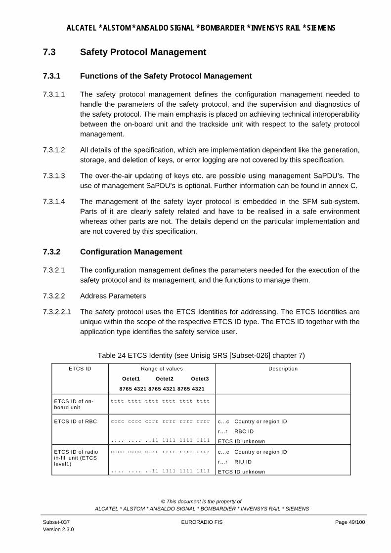
ALCATEL * ALSTOM * ANSALDO SIGNAL * BOMBARDIER * INVENSYS RAIL * SIEMENS
7.3 Safety Protocol Management
7.3.1 Functions of the Safety Protocol Management
7.3.1.1 The safety protocol management defines the configuration management needed to handle the parameters of the safety protocol, and the supervision and diagnostics of the safety protocol. The main emphasis is placed on achieving technical interoperability between the on-board unit and the trackside unit with respect to the safety protocol management.
7.3.1.2 All details of the specification, which are implementation dependent like the generation, storage, and deletion of keys, or error logging are not covered by this specification.
7.3.1.3 The over-the-air updating of keys etc. are possible using management SaPDU’s. The use of management SaPDU’s is optional. Further information can be found in annex C.
7.3.1.4 The management of the safety layer protocol is embedded in the SFM sub-system. Parts of it are clearly safety related and have to be realised in a safe environment whereas other parts are not. The details depend on the particular implementation and are not covered by this specification.
7.3.2 Configuration Management
7.3.2.1 The configuration management defines the parameters needed for the execution of the safety protocol and its management, and the functions to manage them.
7.3.2.2 Address Parameters
7.3.2.2.1 The safety protocol uses the ETCS Identities for addressing. The ETCS Identities are unique within the scope of the respective ETCS ID type. The ETCS ID together with the application type identifies the safety service user.
Table 24 ETCS Identity (see Unisig SRS [Subset-026] chapter 7)
ETCS ID Range of values
Octet1 Octet2 Octet3
8765 4321 8765 4321 8765 4321
Description
ETCS ID of on-board unit
tttt tttt tttt tttt tttt tttt
ETCS ID of RBC cccc cccc ccrr rrrr rrrr rrrr
.... .... ..11 1111 1111 1111
c…c Country or region ID
r…r RBC ID
ETCS ID unknown
ETCS ID of radio in-fill unit (ETCS level1)
cccc cccc ccrr rrrr rrrr rrrr
.... .... ..11 1111 1111 1111
c…c Country or region ID
r…r RIU ID
ETCS ID unknown
© This document is the property of ALCATEL * ALSTOM * ANSALDO SIGNAL * BOMBARDIER * INVENSYS RAIL * SIEMENS
Subset-037 Version 2.3.0
EURORADIO FIS Page 49/100

ALCATEL * ALSTOM * ANSALDO SIGNAL * BOMBARDIER * INVENSYS RAIL * SIEMENS
ETCS ID Range of values
Octet1 Octet2 Octet3
8765 4321 8765 4321 8765 4321
Description
ETCS ID of KM entity
cccc cccc cckk kkkk kkkk kkkk
c…c Country or region ID
k…k Key management entity ID
7.3.2.2.2 Note: The definition of ETCS ID structure and values is out of scope for this FIS.
7.3.2.2.3 Identities are used during the connection set-up to compute the corresponding safety association, i.e. the ETCS IDs are relevant for the execution of the safety procedure peer entity authentication.
7.3.2.2.4 A safety association is defined between two ETCS-Identities as soon as they share a common authentication key to set up a safe connection. Besides the authentication key, also the other parameters have to be defined for every safety association.
7.3.2.2.5 Additionally, the transport service access points (TSAPs) are used by the safety layer to access the transport layer.
7.3.2.3 Timer Parameter
7.3.2.3.1 The parameter maximum connection establishment delay is used for detecting unacceptable delay during the connection establishment.
Table 25 Safety layer timer parameter
Parameter Symbol Applied value Comments
Maximum connection establishment delay
Testab 40 s Depends on the communication network
7.3.3 Supervision and Diagnostics
7.3.3.1 The supervision and diagnostics describes the error management of the safety layer and the monitoring and auditing of safety relevant events.
7.3.3.2 The error management defines the error handling, and the error reporting to the application layer, as far as it is needed for interoperability reasons.
7.3.3.3 NOTE: Error logging by SFM is not required for Class 1. It has to be done by the application, if required.
7.3.3.4 Error Reporting
7.3.3.4.1 All safety relevant errors that occur in the safety layer which are treated by the application have to be reported to the application immediately after their occurrence. Errors handled internally by the safety layer management, may be reported to the application but do not have to be. There are two possibilities for reporting errors to the application:
© This document is the property of ALCATEL * ALSTOM * ANSALDO SIGNAL * BOMBARDIER * INVENSYS RAIL * SIEMENS
Subset-037 Version 2.3.0
EURORADIO FIS Page 50/100

ALCATEL * ALSTOM * ANSALDO SIGNAL * BOMBARDIER * INVENSYS RAIL * SIEMENS
• If the error leads to a mandatory connection release, it can be reported to the application using the service primitive Sa-DISCONNECT.indication. The application is informed about the type of the error using the parameter disconnect reason.
• If the error is only treated internally by the safety layer management or does not lead to a mandatory connection release it can be reported optionally to the application using the service primitive Sa-REPORT.indication. The application is informed about the type of the error by the parameter tuple (reason code, sub-reason code).
7.3.3.5 Error Handling
7.3.3.5.1 If an error occurs in the safety layer the error management has to undertake the following actions depending on the reason and sub-reason of this error. One indicated reason may be caused by different sub-reasons which may be detected by symptoms requiring different error handling actions. The tuples (reason code, sub-reason code) are applied in the Sa-DISCONNECT.indication and Sa-REPORT.indication to indicate the type of the error to the user of the service.
7.3.3.5.2 An error handling action implies the sending of T-DISCONNECT.request (+DI SaPDU), if requested according to state table .
7.3.3.5.3 Class 1 requirement: When error information is transmitted to the application by Sa-DISCONNECT.indication, it is the responsibility of the application for further action.
7.3.3.5.4 The error indication provided by T-DISCONNECT.indication shall be handled by the safety layer:
• When reason = Network error is received, this error is forwarded to the application.
• The reason = Called TS user not available should not be received from the Communication Layer, as the ATP is supposed to be supported by the peer entity. However, if this reason is received by the safety layer, the application will be informed.
Table 26 Normal release
Reason Code
Sub-reason Code
Description Error handling action
0 Normal release requested by peer SFM user
Sa-DISCONNECT.indication
Table 27 Sub-reasons for the reason 'No transport service available'
Reason Code
Sub-reason Code
Description Error handling action
1 1 Network error Sa-DISCONNECT.indication
The application should try to establish
© This document is the property of ALCATEL * ALSTOM * ANSALDO SIGNAL * BOMBARDIER * INVENSYS RAIL * SIEMENS
Subset-037 Version 2.3.0
EURORADIO FIS Page 51/100

ALCATEL * ALSTOM * ANSALDO SIGNAL * BOMBARDIER * INVENSYS RAIL * SIEMENS
Reason Code
Sub-reason Code
Description Error handling action
again the connection
1 2 Network resource not available Sa-DISCONNECT.indication
The application should try to establish again the connection with a lower quality of service parameter
1 3 Service or option is temporarily not available
Sa-DISCONNECT.indication
The application should try to establish again the connection with a modified parameter .
1 5 Reason unknown Sa-DISCONNECT.indication
1 6 Called TS user not available Sa-DISCONNECT.indication
The application should try to establish again the connection with short dialling code
1 8 No mobile station has been registered Sa-DISCONNECT.indication
The application should re-try network registration
NOTE: 1.The sub-reason is equivalent to the reason of T-DISCONNECT.indication.
2. Sub-reasons are a matter of implementation. The error codes are not transmitted via the air interface
Table 28 Sub-reasons for the reason 'Missing parameter or invalid parameter value'
Reason Code
Sub-reason Code
Description Error handling action
3 2 Missing authentication key Sa-DISCONNECT.indication.
3 3 Other problem related to the key management (e.g. loss of session key).
Sa-DISCONNECT.indication. The SFM user can set-up a new connection.
3 29 Requested safety feature is not supported Sa-DISCONNECT.indication
Table 29 Sub-reasons for the reason 'Invalid MAC'
Reason Code
Sub-reason Code
Description Error handling action
4 1 MAC error Sa-REPORT.indication
4 2 MAC error in AU2 SaPDU. Sa-DISCONNECT.indication.
4 3 MAC error in AU3 SaPDU
T-DISCONNECT.request.
4 4 MAC error in AR SaPDU Sa-DISCONNECT.indication
Table 30 Sub-reasons for the error type 'failure in sequence integrity'
© This document is the property of ALCATEL * ALSTOM * ANSALDO SIGNAL * BOMBARDIER * INVENSYS RAIL * SIEMENS
Subset-037 Version 2.3.0
EURORADIO FIS Page 52/100

ALCATEL * ALSTOM * ANSALDO SIGNAL * BOMBARDIER * INVENSYS RAIL * SIEMENS
Reason Code
Sub-reason Code
Description Error handling action
5 1 Replay of authentication message (AU1 SaPDU, AU2 SaPDU, AU3 SaPDU, AR SaPDU) after connection establishment. Error code is used, if the error is not covered by reason code 9.
Sa-DISCONNECT.indication
7.3.3.5.5 Error type: Failure in the direction flag
7.3.3.5.6 This check is performed after the check of the MAC (not in the case of AU1 or DI SaPDU). If there is a transmission error that affects the flag, the MAC will detect this, and the reaction will be as in table 29. If the MAC is correct, but the flag is not correct, there will be a SA-DISCONNECT.indication.
Table 31 Sub-reasons for the reason 'Failure in the direction flag'
Reason Code
Sub-reason Code
Description Error handling action
6 1 Value of direction flag '0' instead of '1' Sa-DISCONNECT.indication
The application is supposed to request a new connection establishment.
6 2 Value of direction flag '1' instead of '0' Sa-DISCONNECT.indication (after previous Sa-CONNECT.indication)
The application is supposed to request a new connection establishment.
. Table 32 Sub-reasons for the reason ‘Time out at connection establishment’
Reason Code
Sub-reason Code
Description Error handling action
7 3 Time out of Testab without receiving the AR SaPDU
Sa-DISCONNECT.indication
The application is supposed to request a new connection establishment.
Table 33 Sub-reasons for the reason 'Invalid SaPDU field'
Reason Code
Sub-reason Code
Description Error handling action
8 1 Invalid information field Rejection of SaPDU
8 4 Invalid responding ETCS Id in AU2, i.e. ETCS-Identity does not correspond to an acceptable ETCS ID.4
Sa-DISCONNECT.indication
4 If there is a call establishment request to an unknown RBC any one of the possible RBCs can be an expected one.
© This document is the property of ALCATEL * ALSTOM * ANSALDO SIGNAL * BOMBARDIER * INVENSYS RAIL * SIEMENS
Subset-037 Version 2.3.0
EURORADIO FIS Page 53/100

ALCATEL * ALSTOM * ANSALDO SIGNAL * BOMBARDIER * INVENSYS RAIL * SIEMENS
Reason Code
Sub-reason Code
Description Error handling action
8 5 Invalid AU1 SaPDU : the header indicates a AU1 SaPDU, but the rest of the Sa PDU does not match with the structure of an AU1 SaPDU.
Rejection of SaPDU
Table 34 Sub-reasons for the reason 'Failure in sequence of the SaPDUs during connection set-
up'
Reason Code
Sub-reason Code
Description Error handling action
9 1 Transmission of AU1 SaPDU but a message different from AU2 SaPDU is obtained.
Sa-DISCONNECT.indication
9 2 Transmission of AU2 SaPDU but a message different from AU3 SaPDU is obtained.
T-DISCONNECT.request
9 3 Transmission of AU3 SaPDU but a message different from AR SAPDU is obtained.
Sa-DISCONNECT.indication
Table 35 Sub-reasons for the reason ' SaPDU length error '
Reason Code
Sub-reason Code
Description Error handling action
10 1 AU1 SaPDU length error Rejection of AU1 SaPDU
10 2 AU2 SaPDU length error Sa-DISCONNECT.indication
10 3 AU3 SaPDU length error T-DISCONNECT.request
10 5 DT SaPDU length error Sa-DISCONNECT.indication
10 8 AR SaPDU length error Sa-DISCONNECT.indication
7.3.3.5.7 The code 127 (unknown) has to be used, when
• no proper reason code or subreason code can be selected
• the reason code or subreason code is undefined
7.3.3.5.8 The reason codes 11-126 are reserved for future use. The reason codes 128-255 are reserved for national use/implementation specific use. For these reason codes the subreason codes (0...126, 128...255) are also reserved for national use / implementation specific use.
© This document is the property of ALCATEL * ALSTOM * ANSALDO SIGNAL * BOMBARDIER * INVENSYS RAIL * SIEMENS
Subset-037 Version 2.3.0
EURORADIO FIS Page 54/100

ALCATEL * ALSTOM * ANSALDO SIGNAL * BOMBARDIER * INVENSYS RAIL * SIEMENS
8. COMMUNICATION FUNCTIONAL MODULE 8.0.0.1 This chapter specifies the Communication Functional Module (CFM), its services, and
the protocol stack based on circuit switched bearer services of GSM PLMNs and fixed networks. The CFM covers the OSI layers 4 (transport layer), 3 (network layer), and 2 (data link layer).
8.0.0.2 NOTE: The service interface is not mandatory for Class 1. The service primitives of Annex B describe the interface at a functional level only.
8.1 Service definition
8.1.1 Model of communication services
8.1.1.1 The communication services that the RCS Communication Functional Module offers to its users (Safe Functional Module and optionally non-safe users) are based on the services provided by the transport layer of ISO/OSI reference model [X.214]. These services concern:
• Transport connection establishment/release
• Reliable data transmission
• Transparent data transmission.
8.1.1.2 Additionally, the transmission of high priority data is provided.
8.1.1.3 A communication functional module offers also reliability enhancement of the transmission channel.
8.1.1.4 A CFM entity communicates with its users (CFM user5 ) through one or more Transport Service Access Point (TSAP) by means of transport service primitives. The CFM entities supporting a transport connection exchange Transport Protocol Data Units (TPDU) for normal data use the service of the lower layers, through the respective Service Access Points.
8.1.1.5 The service for high priority data is described in section 8.1.5.
8.1.1.6 Optionally, more than one transport connection per physical channel can be supported by a CFM. This option is not required for ETCS level 1 radio in-fill unit.
8.1.1.7 Figure 13 contains a model only. It does not restrict any implementations.
8.1.2 Connection establishment
8.1.2.1 The process of establishing a transport connection is initiated at the time where the communication service user requests a connection set up to Communication
5 CFM user is applied to indicate a service user of the CFM. The correct OSI term would be TS user.
© This document is the property of ALCATEL * ALSTOM * ANSALDO SIGNAL * BOMBARDIER * INVENSYS RAIL * SIEMENS
Subset-037 Version 2.3.0
EURORADIO FIS Page 55/100

ALCATEL * ALSTOM * ANSALDO SIGNAL * BOMBARDIER * INVENSYS RAIL * SIEMENS
Functional Module. This service is accessed through the service primitive T-CONNECT.request with its associated parameters at the TSAP. At the time of connection set up request, the user has the possibility to specify its needs by means QoS class and of the application type to be served.
CFM user
TS entity TS entity
TSAP
Normal data (queued) High priority data
Logical data flow : normal data
High priority data Normal data High priority data Normal data
CFM
NSAP NSAP
CFM user
DLSAP
HDLC entity HDLC entity
Normal data
High priority data
DLSAP
TSAP
Symbol of a queue Figure 13 Model of communication service
8.1.2.2 The communication functional module evaluates the value of the QoS class and the application type. The associated set of quality of service parameter values will be used
• to select the proper bearer service for physical connection establishment, when this connection does not yet exist;
• optionally, to select the scheduling features of transport layer multiplexing.
8.1.3 Data transfer
8.1.3.1 The data transfer service is provided after a successful transport connection set up. This service is accessed through the service primitive T-DATA.request with its associated parameters at the TSAP. The Communication Functional Module provides
© This document is the property of ALCATEL * ALSTOM * ANSALDO SIGNAL * BOMBARDIER * INVENSYS RAIL * SIEMENS
Subset-037 Version 2.3.0
EURORADIO FIS Page 56/100

ALCATEL * ALSTOM * ANSALDO SIGNAL * BOMBARDIER * INVENSYS RAIL * SIEMENS
transparent and reliable transfer of user data in both directions simultaneously, and hides to its users the way in which the data are handled internally.
8.1.4 Connection release
8.1.4.1 The transport connection release is provided by the Communication Functional Module through the use of the transport service primitive T-DISCONNECT.request, with its associated parameters. The connection release due to the Communication Functional Module, or caused by lower layers, will be indicated to the user.
8.1.5 High priority data
8.1.5.1 The HP data transfer service is an additional service provided for the transport connection with the application type ATP only (refer to section 8.2.4.6). HP data will be transferred with the highest transport priority in respect to data of all transport connections multiplexed on the same physical connection.
8.1.5.2 The service is accessed through the additional service primitive T-HP-DATA.request with its associated parameters at the TSAP.
8.1.5.3 Layers 4 and 3 protocol stack of the user plane is empty. Protocols which add headers are not specified. The user data are exchanged between the CFM users and layer 2. These data are immediately transmitted, by-passing any existing queues. All data will be routed to the peer CFM user, i.e. to the CFM user with the application type ATP. Multiplexing of HP data streams for different transport connections on the same physical connection is not possible.
8.1.5.4 NOTE: In the case of more than one receiving CFM users of application type ATP multiplexed on the same physical connection, the receiving CFM entity shall transfer the HP data to all CFM users of application type ATP.
8.1.5.5 Layer 2 sends/receives these data - and only this type of data - as UI-frames. In the case of erroneous or lost UI frames, layer 2 does not repeat the transmission. Acknowledgement and repetition shall be provided if required by the CFM users.
8.1.5.6 Segmenting and reassembling of the user data is not possible. The user data length is restricted to the length of the data field of the UI frame.
8.1.5.7 Class 1 requirement: It is mandatory to transfer HP data from RBC to the train.
8.1.6 Quality of Service
8.1.6.1 The term Quality of Service (QoS) refers to certain characteristics of a transport connection as observed between the endpoints.
8.1.6.2 The QoS parameters give transport service (TS) users a method of specifying their needs, and give the TS provider a basis for selection of the protocol or for requesting services of lower layers. The QoS is normally negotiated between the TS users and the
© This document is the property of ALCATEL * ALSTOM * ANSALDO SIGNAL * BOMBARDIER * INVENSYS RAIL * SIEMENS
Subset-037 Version 2.3.0
EURORADIO FIS Page 57/100

ALCATEL * ALSTOM * ANSALDO SIGNAL * BOMBARDIER * INVENSYS RAIL * SIEMENS
TS provider on a per transport connection basis, using the T-CONNECT request, indication, response, and confirm TS primitives. The negotiated QoS values then apply throughout the lifetime of the transport connection. For the purposes of this FIS for the use in the transport protocol the values for all parameters are fixed for a given application type, in which case QoS negotiation on a per transport connection basis is restricted to local negotiation between the requesting side and its local transport providing entity.
8.1.6.3 There is no guarantee that the originally negotiated QoS will be maintained throughout the transport connection lifetime. The Transport Service provider does not explicitly signal changes in QoS.
8.1.6.4 Possible choices and default values for each parameter will normally be specified at the time of initial TS provider installation.
8.2 Communication protocols
8.2.1 Introduction
8.2.1.1 This section provides a precise specification of the communication protocols of the user channel. The protocol specifications are described layer by layer as delta specifications to existing standards.
8.2.2 Data Link Layer
8.2.2.1 According to the OSI reference model the reliable transfer of data is provided by the data link layer. The data link layer of the B/Bm-channel provides functional and procedural means to establish, maintain, and release connections and to transfer data. It will detect and correct data transfer errors, which may occur in the physical layer.
8.2.2.2 The protocol of layer 2 (DTE-DTE communication) will transmit data according to the sequence of their data request primitives.
8.2.2.3 The layer 2 protocol is covered by the HDLC standards. The application conditions are given as delta specifications.
8.2.2.4 The frame structure according to [ISO/IEC 3309] and the elements of the control procedures according to [ISO/IEC 4335] shall be used.
8.2.2.5 The HDLC balanced asynchronous class (BAC) of procedures shall be used. The HDLC basic procedure shall provide the following error detection and recovery features:
• automatic re-transmission after missing acknowledge;
• 16 bit frame check sequence.
8.2.2.6 Some standardised options of HDLC are required as defined in [ISO/IEC 7809]:
© This document is the property of ALCATEL * ALSTOM * ANSALDO SIGNAL * BOMBARDIER * INVENSYS RAIL * SIEMENS
Subset-037 Version 2.3.0
EURORADIO FIS Page 58/100

ALCATEL * ALSTOM * ANSALDO SIGNAL * BOMBARDIER * INVENSYS RAIL * SIEMENS
• option 3.2: multi-selective reject (SREJ);
• option 4: unnumbered information (UI)6;
• option 10: extended sequence numbering (SABME);
• option 15.1Start/stop transmission. Note: Option 8 is not used (see 8.2.2.9). Note: Option 2 is not used.
8.2.2.7 The elements supporting the procedure and options are described in [ISO/IEC 7776] except for the following rules7:
a) Only the single link procedure is used.
b) An independent HDLC protocol is used in each B/Bm channel.
c) In the case of concurrent transmission requests for the data link (one I frame and one UI frame), the UI frame has to be transmitted with higher priority.
d) An ”unsolicited DM” is not used.
e) In the case of FRMR condition link reset shall not be used. The receiver of FRMR shall send a DISC frame as a response (see [ISO/IEC 7776] section 5.6).
f) An ”unsolicited UA response frame” in the information transfer phase is ignored.
g) ”Basic mode of operation” is not used.
h) Extended sequence numbering (modulo 128) is used.
i) The calling system plays the DTE role and the called system plays the DCE role. These roles include the layer 2 addressing. The system initiating the establishment of the B/Bm channel is considered to be the calling system.
j) The end system with the DTE role is responsible for the establishment and release of the layer 2 connection. Only the end system with the DTE role is allowed to send SABME frames. However, the other system can also release the connection.
k) In the case of ordered release of the connection, the layer 2 connection should be released before the B/Bm channel.
l) The interframe time fill-in shall be “Mark”.
m) The layer 2 protocol shall not insert any inter-octet time fill-in (ISO 4335 §4.1.4.2).
n) Only control escape transparency shall be used (ISO/IEC7776 §3.5.2.2).
8.2.2.8 The order of transmitting bits within each octet in the information field is to send the least significant bit first.
6Applied for HP data. In the case of error, there is no layer 2 re-transmission . 7 For further detailed information see Annex D.
© This document is the property of ALCATEL * ALSTOM * ANSALDO SIGNAL * BOMBARDIER * INVENSYS RAIL * SIEMENS
Subset-037 Version 2.3.0
EURORADIO FIS Page 59/100

ALCATEL * ALSTOM * ANSALDO SIGNAL * BOMBARDIER * INVENSYS RAIL * SIEMENS
8.2.2.9 Response I frames shall be sent only with F=1. Response I frames with F=0 shall not be sent.
8.2.2.10 SREJ shall be sent as response frame only.
8.2.2.11 UI frames can be sent either as command or as response; the receiver shall not check it. The receiver shall not check the P/F bit, which can be set to 1 or 0.
8.2.3 Network Layer
8.2.3.1 Co-ordinating Function
8.2.3.1.1 The co-ordinating function provides the synchronisation mechanism required between the usage of the B/Bm- channel protocol stack and the signalling protocol stack.
8.2.3.1.2 The following tasks shall be performed by the co-ordinating function:
a) Registration with requested/appropriate GSM PLMN.
b) Establishment of network connection(s) by means of the GSM 07.07 and ETS 300102 signalling protocol.
c) Mapping of the requested QoS parameters into signalling information.
d) Connection refusal when applicable
e) Connection release by means of the GSM 07.07 and ETS 300102 signalling protocols
f) Handling of the GSM/ISDN supplementary services information.
g) Error reporting and retrieving information on error reasons received from GSM 07.07 and ETS 300102 signalling protocols.
h) disconnect of data link layer followed by release of physical connection in case of disconnect phase (e.g. when the number of retransmission attempts exceeds N2 or in case of FRMR condition detected) (see ISO/IEC 7776 section 5.3.3, 5.3.4).
8.2.3.1.3 If a B/Bm-channel connection is not already established, the receipt of an N-CONNECT.request primitive shall cause the control plane signalling procedures for circuit switched connection to establish a B/Bmchannel connection. The requested QOS parameters for the N-connection shall be mapped onto user-network signalling information elements.
8.2.3.1.4 During B/Bm- channel connection establishment, supplementary services information and signalling protocol cause codes shall be handled as specified in [GSM/R interfaces].
8.2.3.1.5 NOTE: A simplified handling of signalling information and error reasons is allowed for Class 1.
© This document is the property of ALCATEL * ALSTOM * ANSALDO SIGNAL * BOMBARDIER * INVENSYS RAIL * SIEMENS
Subset-037 Version 2.3.0
EURORADIO FIS Page 60/100

ALCATEL * ALSTOM * ANSALDO SIGNAL * BOMBARDIER * INVENSYS RAIL * SIEMENS
8.2.3.1.6 When the B/Bm- channel connection is established in layer 1, the co-ordinating function informs the B/Bm- channel network layer entity and B/Bm- channel data link layer entity. The data link layer entity performs synchronisation with its peer data link layer entity and informs the network layer entity after successful synchronisation.
8.2.3.1.7 Each RCS has to operate one or more B/Bm-channels with peer RCS. The layer 3 and layer 2 entities are processed independently in each B/Bm- channel.
8.2.3.1.8 When the N-DISCONNECT.request is received, the B/Bm- channel is released by the GSM 07.07 and ETS 300102 signalling protocols.
8.2.3.2 B/BmChannel network Layer
8.2.3.2.1 According to the OSI reference model the network layer of a B/Bm- channel provides functional and procedural means to establish, maintain, and release network connections between open systems containing communicating transport entities independent from routing and relay considerations.
8.2.3.2.2 For Layer 3, the T.70 network layer protocol for CSPDNs shall be used in the B/Bm- channel. Only the T.70 header (refer to T.70 Section 3.3.3 and Figure 14) is applied: Segmentation/re-assembly of the NSDU out of/into sequences of NPDUs and setting of the M-Bit.
8.2.3.2.3 NOTE: ISDN B-channel circuit switched mode: T.90 specifies in appendix II the T.70 network layer protocol as an optional protocol usable on a per call basis.
0 0 0 0 0 0 0 11
M Q 0 0 0 0 0 02
3...n network user data field
8 1
MSB
...
LSB
Figure 14 Format of NPDU
8.2.3.2.4 When the more data mark (M) is set to 1 it indicates that more data is to follow. The Q-bit is reserved; currently the value is set to 0.
8.2.3.2.5 Error handling of T.70 header is a matter of implementation.
8.2.4 Transport Layer
8.2.4.1 Functions
© This document is the property of ALCATEL * ALSTOM * ANSALDO SIGNAL * BOMBARDIER * INVENSYS RAIL * SIEMENS
Subset-037 Version 2.3.0
EURORADIO FIS Page 61/100

ALCATEL * ALSTOM * ANSALDO SIGNAL * BOMBARDIER * INVENSYS RAIL * SIEMENS
8.2.4.1.1 The transport layer only establishes a transport connection if a network connection exists. If the network connection does not exist at the moment when an association is requested, the transport entity first of all requests the establishment of such a connection and then automatically sets up the transport connection. Each different application type should have established its own transport connection for the intended duration of the communication. TP2 shall be used in order to provide more than one transport connection over the same network connection.
8.2.4.1.2 The layer 4 protocol is covered by ITU-T Rec. X.224 ”Protocol for providing the OSI connection-mode transport service”; the application conditions are given as delta specifications in section 8.2.4.7. The elements of transport procedure class 2 (TP2) listed in Table 36 shall be used. Some special problems of the protocol are described in the following sections.
Table 36 Procedure elements of TP2
Protocol mechanism X.224 Cross-
ref.
Variant or Option TP Class 2 used not used
Assignment to network connection 6.1.1 x *
TPDU transfer 6.2 x *
Segmenting and reassembling 6.3 x *
Concatenation and separation 6.4 x *
Connection establishment 6.5 x *
Connection refusal 6.6 x *
Normal release 6.7 Explicit x *
Error release 6.8 x *
Association of TPDU’s with transport connection
6.9
x
*
TPDU numbering 6.10 Normal
Extended
m (Note 1)
o (Note 1)
*
*
Expedited data transfer 6.11 Network Expedited x (Note 1) *
Reassignment after failure 6.12 na *
Retention and acknowledgement of TPDU’s
6.13 Confirmation of receipt na *
Re synchronisation 6.14 na *
Multiplexing and de-multiplexing 6.15 x (Note 2) (Note 3)
*
Explicit flow control 6.16 m *
Checksum 6.17 x *
Frozen references 6.18 *
Re transmission on time-out 6.19 na *
Resequencing 6.20 na *
Inactivity control 6.21 na *
Treatment of protocol errors 6.22 x *
Splitting and recombining 6.23 *
© This document is the property of ALCATEL * ALSTOM * ANSALDO SIGNAL * BOMBARDIER * INVENSYS RAIL * SIEMENS
Subset-037 Version 2.3.0
EURORADIO FIS Page 62/100

ALCATEL * ALSTOM * ANSALDO SIGNAL * BOMBARDIER * INVENSYS RAIL * SIEMENS
Protocol mechanism X.224 Cross-
ref.
Variant or Option TP Class 2 used not used
NOTES
X Procedure always included in class 2 na Not applicable in TP class 2 m Negotiable procedure whose implementation in equipment is mandatory o Negotiable procedure whose implementation in equipment is optional 1 Not applicable in class 2 when non-use of explicit flow control is selected. 2 Multiplexing may lead to degradation of the quality of service if the non-use of explicit flow control has been selected. 3 Option. This option is not required for ETCS level1 radio in-fill unit.
8.2.4.2 Priority handling
8.2.4.2.1 The priority has to be handled:
• during set-up phase of the physical connection (”eMLPP priority”): The GSM phase 2+ supplementary service ”Enhanced Multi-Level Precedence and Pre-emption service (eMLPP)” [GSM 02.67] will provide different levels of priority for call set-up and for call continuity. The GSM PLMN operator allocates set-up classes and pre-emption capabilities to each priority level according to the railway specifications (refer to EIRENE SRS). The priority is requested during set-up of the physical connection by the co-ordination function. The priority level 1 (Control-command safety) will be used for all application types.
• by the scheduling algorithm during multiplexing (”transport priority”): A transport priority is defined for the different application types (see section 8.3.2.2)
8.2.4.2.2 NOTE: All priority treatment of the transport layer refers to transport priorities.
8.2.4.2.3 The action taken by the transport protocol during connection lifetime is not explicitly defined in X.224.
8.2.4.2.4 The following policy has to be adopted in each CFM at transport connection set-up request:
• If sufficient resources are available to provide the service (in both the local and distant system) the new connection will be established.
• Otherwise the connection request is refused.
8.2.4.2.5 The handling of transport priority during the data phase of the transport connection is specified in the following section.
8.2.4.3 Multiplexing
8.2.4.3.1 Multiplexing of two or more transport connections onto a single network connection can be provided as an option. This option is not required for ETCS level 1 radio in-fill unit.
8.2.4.3.2 Multiplexing requires the following functions:
© This document is the property of ALCATEL * ALSTOM * ANSALDO SIGNAL * BOMBARDIER * INVENSYS RAIL * SIEMENS
Subset-037 Version 2.3.0
EURORADIO FIS Page 63/100

ALCATEL * ALSTOM * ANSALDO SIGNAL * BOMBARDIER * INVENSYS RAIL * SIEMENS
a) The identification of the transport connection source is provided by an appropriate DST-REF parameter of each DT TPDU and additionally the SRC-REF parameter of CR, CC, DR, and DC TPDUs. These parameters are used to identify each TPDU in a given transport connection and ensures that data from different transport connections are not mixed or mis-routed.
b) Peer flow control regulates the rate at which TPDUs of individual transport connections are sent to the peer transport entity. The use of explicit flow control on each transport connection will conform to X.224 recommendation sub-section 10.2.4.2 and will be used in addition to any other form of flow control performed in the lower layers.
c) The scheduling of the next transport connection to be served over the network connection: The connection associated with application type ATP has to be served first.
d) The transport connection endpoint identifier (TCEPID) at the TSAP provides local identification of the transport connection. Service boundary flow control is provided as a matter of implementation. These local flow control mechanisms shall be in accordance to transport priority requests.
8.2.4.4 Release of the network connection
8.2.4.4.1 The release of network connection occurs when all the transport connections associated with it have been released.
8.2.4.4.2 In the case of an abnormal release by the network, all associated transport connections are released and the transport service users are immediately informed.
8.2.4.5 Segmenting/reassembling
8.2.4.5.1 If the size of the transport service data unit (TSDU), which is requested for transmission to the transport layer, exceeds the maximum size of the user data part of the DT TPDU, then segmentation must first be performed on the TSDU. One TSDU is mapped into more than one TPDU with added protocol control information.
8.2.4.5.2 The segmenting/reassembling reduces the throughput because of the increased overhead in the TPDUs. Normal priority user data is segmented, if it does not fit into one TPDU. The recommended length of TSDUs is <= 123 octets.
8.2.4.5.3 The transmitting transport entity should apply the length 128 octets for all TPDUs except the last one.
8.2.4.5.4 The peer transport entity has to identify the transport connection of the received segments and to reassemble the segments into the TSDU.
8.2.4.5.5 The receiving transport entity shall be able to accept TPDUs of different length: from 1 up to 128 octets.
8.2.4.5.6 If one TPDU (which is requested for transmission to the network layer as NSDU) is handled by the network entity, the next TPDU has to wait. Segmenting of long lower
© This document is the property of ALCATEL * ALSTOM * ANSALDO SIGNAL * BOMBARDIER * INVENSYS RAIL * SIEMENS
Subset-037 Version 2.3.0
EURORADIO FIS Page 64/100
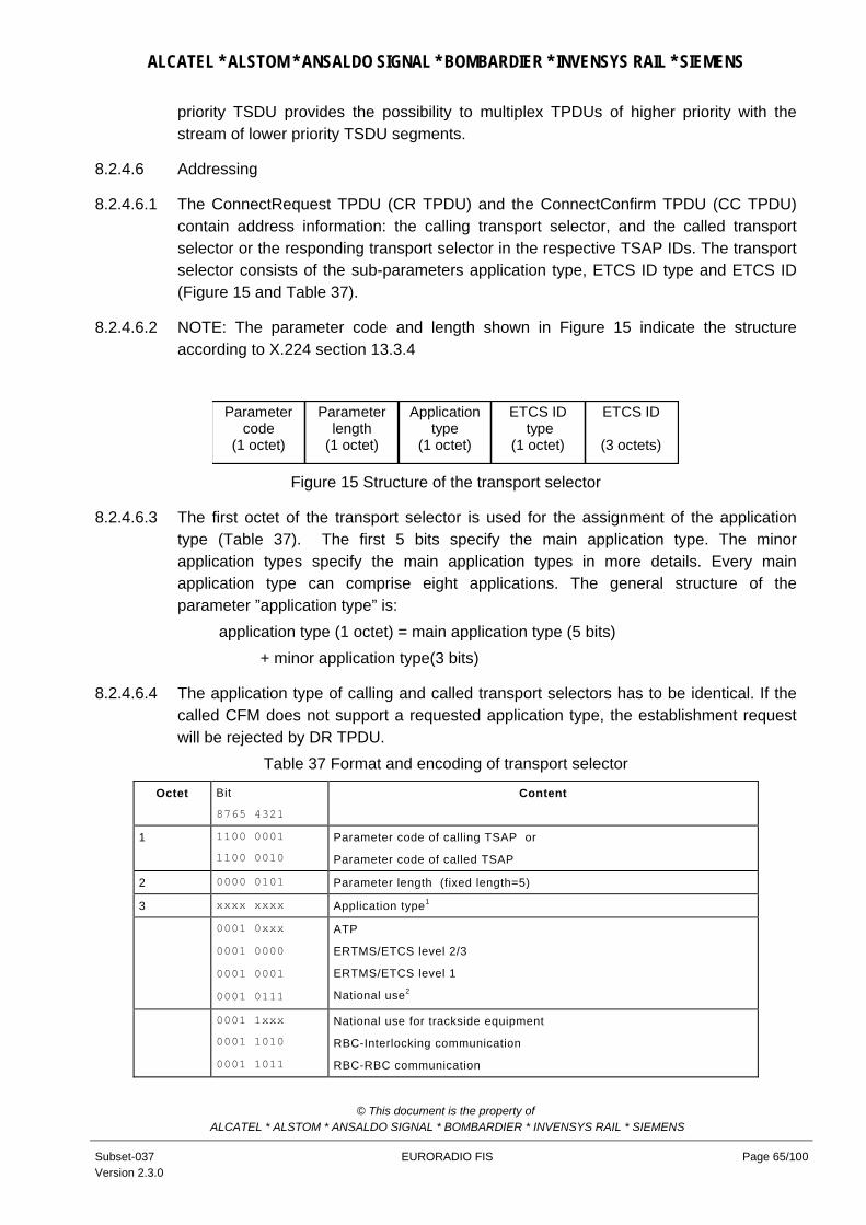
ALCATEL * ALSTOM * ANSALDO SIGNAL * BOMBARDIER * INVENSYS RAIL * SIEMENS
priority TSDU provides the possibility to multiplex TPDUs of higher priority with the stream of lower priority TSDU segments.
8.2.4.6 Addressing
8.2.4.6.1 The ConnectRequest TPDU (CR TPDU) and the ConnectConfirm TPDU (CC TPDU) contain address information: the calling transport selector, and the called transport selector or the responding transport selector in the respective TSAP IDs. The transport selector consists of the sub-parameters application type, ETCS ID type and ETCS ID (Figure 15 and Table 37).
8.2.4.6.2 NOTE: The parameter code and length shown in Figure 15 indicate the structure according to X.224 section 13.3.4
Applicationtype
(1 octet)
ETCS ID type
(1 octet)
ETCS ID
(3 octets)
Parameterlength
(1 octet)
Parametercode
(1 octet)
Figure 15 Structure of the transport selector
8.2.4.6.3 The first octet of the transport selector is used for the assignment of the application type (Table 37). The first 5 bits specify the main application type. The minor application types specify the main application types in more details. Every main application type can comprise eight applications. The general structure of the parameter ”application type” is: application type (1 octet) = main application type (5 bits) + minor application type(3 bits)
8.2.4.6.4 The application type of calling and called transport selectors has to be identical. If the called CFM does not support a requested application type, the establishment request will be rejected by DR TPDU.
Table 37 Format and encoding of transport selector
Octet Bit
8765 4321
Content
1 1100 0001
1100 0010
Parameter code of calling TSAP or
Parameter code of called TSAP
2 0000 0101 Parameter length (fixed length=5)
3 xxxx xxxx Application type1
0001 0xxx
0001 0000
0001 0001
0001 0111
ATP
ERTMS/ETCS level 2/3
ERTMS/ETCS level 1
National use2
0001 1xxx
0001 1010
0001 1011
National use for trackside equipment
RBC-Interlocking communication
RBC-RBC communication
© This document is the property of ALCATEL * ALSTOM * ANSALDO SIGNAL * BOMBARDIER * INVENSYS RAIL * SIEMENS
Subset-037 Version 2.3.0
EURORADIO FIS Page 65/100

ALCATEL * ALSTOM * ANSALDO SIGNAL * BOMBARDIER * INVENSYS RAIL * SIEMENS
Octet Bit
8765 4321
Content
0001 1100 Interlocking-Interlocking communication
0010 0xxx
0010 0000
0010 0001
Key management
KMC/KMC communication
KM domain internal communication
1111 1111 Reserved for error handling
4
0000 0000 0000 0001 0000 0010 0000 0011 0000 0100 0000 0101 0000 0110 1111 1111
ETCS ID type Radio in-fill unit RBC Engine Reserved for Balise Not required for Class 1 Reserved for Field element (Level crossing,...)Not required for Class 1 Key management entity Interlocking related entity Unknown 3
5-7 ETCS ID
NOTE:
1. Application type ATP is mandatory. All other application type values are reserved.
2. Minor application type “National use” is reserved for non-interoperable national applications.
3. Can only be used together with an ETCS ID value “unknown”.
8.2.5 Applicability conditions of X.224
Table 38 Applicability conditions of X.224
Section Application conditions
Introduction These application conditions only apply for the RCS specification.
§ 1 Transport procedure class 2 (TP class 2) for the connection-oriented data transfer shall be used. All other TP classes of X.224 shall not shall not be used.
”Conformance testing” shall not be used.
§ 4.2 ED, EA, and RJ TPDU shall not be used.
§ 5.1 The communication services are specified in section 8.1.
Tab.1/X.224 shall not be used.
§ 5.2 The network service used is a ”connection oriented network service(CONS)”. The parameter exchange between the transport entity and the network service provider is implementation dependent. The network service primitives according to X.213 should be used.
The following applies for Tab.2a/X.224, if used:
• N-DATA-ACKNOWLEDGE primitives shall not be used.
• N-EXPEDITED-DATA primitives shall not be used. With N-CONNECT primitives, ”receipt confirmation option”, ”expedited data option” and ”NS user data” shall not be used.
• With N-DISCONNECT primitives, ”NS user data” shall not be used.
• N-UNITDATA shall not be used.
• Tab. 2b/X.224 shall not be used.
§ 5.3.1 The future functions ”encryption”, ”accounting mechanisms”, ”status exchange”, ”blocking”, ”temporary release of network connections”, and ”alternative checksum algorithm” shall not be used.
”Monitoring of QoS” shall not be used.
© This document is the property of ALCATEL * ALSTOM * ANSALDO SIGNAL * BOMBARDIER * INVENSYS RAIL * SIEMENS
Subset-037 Version 2.3.0
EURORADIO FIS Page 66/100

ALCATEL * ALSTOM * ANSALDO SIGNAL * BOMBARDIER * INVENSYS RAIL * SIEMENS
Section Application conditions
§ 5.3.1.1 c) ”error detection” shall not be used.
d) ”error recovery” shall not be used.
§ 5.3.1.2 b) All transport connections from trainborne transport layer entity to the same trackside layer entity and vice versa are multiplexed onto one network connection.8 (Option)
c) The default size of the TPDU shall be 128 octets.
e) The called network address, if provided, shall be used as network address. If this network address is not provided by T-CONNECT.request, the ETCS IDs have to be mapped9.
f) A TCEPID should be used to distinguish between transport connections.
g) ”TS user data” can be used.
h) ”inactivity timers” shall not be used.
§ 5.3.1.3 a) ”concatenation and separation” shall not be used.
c) ”splitting and recombining” shall not be used.
f) ”expedited data” shall not be used.
§ 5.4.1 TP class 2 shall be used.
§ 5.4.2 The TP class cannot be negotiated. The accepted class and its options must be equal to the required class 2.
§ 5.4.3 A network connection of Type A is a precondition.
§ 5.4.4 TP class 0 shall not be used.
§ 5.4.5 TP class 1 shall not be used.
§ 5.4.6.2 ”Explicit flow control” shall be used.
§ 5.4.7 TP class 3 shall not be used.
§ 5.4.8 TP class 4 shall not be used.
§ 5.5 TP class 4 with ”connectionless-mode network service (CNLS)” shall not be used.
§ 6.1.1.3 All transport connections between the same pair of transport layer entities are multiplexed onto one network connection.10 (Option)
Procedures for ”re-synchronisation”, ”reassignment after failure” and ”splitting” shall not be used.
Note 3: The value of the appropriate delay should be 0s.11
Note 4: shall not be used.
Note 5: shall not be used.
§ 6.1.2 ”connectionless-mode network service” shall not be used.
§ 6.2.2 N-EXPEDITED-DATA and N-UNITDATA primitives shall not be used.
§ 6.2.3 ”connectionless-mode network service” shall not be used.
The network expedited variant shall not be used.
§ 6.4 ”concatenation and separation” shall not be used.
§ 6.5.2 N-UNITDATA primitives shall not be used.
8Refer to section 8.2.4.3 9Refer to section 8.3.1 10Refer to section 8.2.4.3 11Refer to section 8.2.4.4
© This document is the property of ALCATEL * ALSTOM * ANSALDO SIGNAL * BOMBARDIER * INVENSYS RAIL * SIEMENS
Subset-037 Version 2.3.0
EURORADIO FIS Page 67/100

ALCATEL * ALSTOM * ANSALDO SIGNAL * BOMBARDIER * INVENSYS RAIL * SIEMENS
Section Application conditions
§ 6.5.3 The following TPDU parameters shall not be used:
• use of extended format;
• version number;
• protection;
• checksum;
• additional option selection;
• alternate protocol classes;
• acknowledge time;
• inactivity time;
• residual error rate;
• reassignment time;
• Option “non-use of explicit flow control in class 2”.
The following TPDU parameters should not be used:
• TPDU size (proposed and selected);
• preferred maximum TPDU size (proposed and selected).
If these parameters are used, the receiver shall ignore them.
© This document is the property of ALCATEL * ALSTOM * ANSALDO SIGNAL * BOMBARDIER * INVENSYS RAIL * SIEMENS
Subset-037 Version 2.3.0
EURORADIO FIS Page 68/100

ALCATEL * ALSTOM * ANSALDO SIGNAL * BOMBARDIER * INVENSYS RAIL * SIEMENS
Section Application conditions
§ 6.5.4 Transport connections are only established by the initiator of the network connection.
Optionally, the responder can try to establish a transport connection. If it cannot be negotiated with peer transport layer entity or peer TS user, the transport connection establishment request will be rejected.
”splitting and recombining” shall not be used.
The timer TS1 is a matter of local implementation.
The network expedited variant shall not be used.
a) A TCEPID should be used as a reference.
c) ”initial credit” equals to 15 for transport connections with application type ATP; ”initial credit” equals to 1 for all other transport connections (if option ”Multiplexing” is used).
e) ”acknowledge time” shall not be used.
f) ”checksum” shall not be used.
g) ”protection” shall not be used.
h) ”inactivity time” shall not be used.
o) Option “non-use of explicit flow control in class 2” shall not be used
The following parameters shall not be negotiated:
i) ”Protocol class” shall be always 2; ”alternative class” shall not be used.
Table 3/X.224 shall not be used. The following parameters shall not be negotiated:
j) The default size of the TPDU shall be 128 octets. This shall be maximum size usable.
k) ”Preferred maximum TPDU size” should not be used.
l) ”extended format” shall not be used.
m) ”checksum” shall not be used.
n) The parameter value of ”priority” shall be set according to the value of transport priority12.
p) ”network receipt confirmation” and ”network expedited data transfer” shall not be used.
q) ”transport expedited data transfer” shall not be used.
r) ”use of selective acknowledgement” shall not be used.
s) ”use of request acknowledgement” shall not be used.
t) ”version number” shall not be used.
u) ”reassignment time parameter” shall not be used.
§ 6.5.5 ”connectionless-mode network service” shall not be used.
§ 6.6 The required class and options must be accepted.
§ 6.7.1 The explicit ”release procedure” shall be used.13
§ 6.7.1.4 The implicit ”release procedure” shall not be used. If the network connection is interrupted, an error indication should be given to the application.
§ 6.7.1.5 The orderly release of the transport connection requires the availability of the network connection.
The release may result in discarding of TPDUs.
Note 5: a network connection shall be immediately released in order when all transport connections multiplexed onto the network connection have been released.
Note 6: The timer TS2 is a matter of local implementation.
§6.7.2 ”connectionless-mode network service” shall not be used.
12Refer to section 8.3.2.3.4 13Refer to 8.2.4.4
© This document is the property of ALCATEL * ALSTOM * ANSALDO SIGNAL * BOMBARDIER * INVENSYS RAIL * SIEMENS
Subset-037 Version 2.3.0
EURORADIO FIS Page 69/100

ALCATEL * ALSTOM * ANSALDO SIGNAL * BOMBARDIER * INVENSYS RAIL * SIEMENS
Section Application conditions
§ 6.8 ”Error release” shall be used.
On receipt of N-RESET.indication a N-DISCONNECT.request has to be issued.
§ 6.9.1.2 N-EXPEDITED-DATA primitives shall not be used.
§ 6.9.1.4.2 f) Add: The DST-REF parameter shall be mapped onto the local ”transport connection endpoint identifier (TCEPID)”.
§ 6.9.2 ”connectionless-mode network service” shall not be used.
§ 6.11 ”expedited data transfer” shall not be used.
§ 6.12 ”reassignment after failure” shall not be used.
§ 6.13 ”retention and acknowledgement of TPDUs” shall not be used.
§ 6.14 ”re-synchronisation” shall not be used.
§ 6.15 Details of multiplexing are specified in section 8.2.4.3
§ 6.15.2 ED, EA, and RJ TPDUs shall not be used.
§ 6.15.3 Note 2: ”concatenation” shall not be used.
§ 6.16 Explicit flow control shall be used.
§ 6.17 ”checksum” shall not be used.
§ 6.18 ”frozen reference” shall not be used.
§ 6.19 ”re transmission on time-out” shall not be used.
§ 6.20 ”resequencing” shall not be used.
§ 6.21 ”inactivity control” shall not be used.
§ 6.22.2 ”connectionless-mode network service” shall not be used.
§ 6.23 ”splitting and combining” shall not be used.
§ 7 Tab.6/X.224 shall not be used. Refer to Table 36.
§ 8 TP class 0 shall not be used.
§ 9 TP class 1 shall not be used.
§ 10.2.1 d) ”concatenation and separation” shall not be used.
f) ”multiplexing and de-multiplexing” are used.
§ 10.2.3 Data transfer without flow control shall not be used.
§ 10.2.4.1 ”segmenting and reassembling” are used.
§ 10.2.4.3 ”Expedited data transfer” shall not be used.
§ 11 TP class 3 shall not be used.
§ 12 TP class 4 shall not be used.
§ 13.1 Table 8/X.224: ED, EA and RJ TPDUs shall not be used.
© This document is the property of ALCATEL * ALSTOM * ANSALDO SIGNAL * BOMBARDIER * INVENSYS RAIL * SIEMENS
Subset-037 Version 2.3.0
EURORADIO FIS Page 70/100

ALCATEL * ALSTOM * ANSALDO SIGNAL * BOMBARDIER * INVENSYS RAIL * SIEMENS
Section Application conditions
§ 13.3.3 b) ”initial credit” equals 15 for transport connections with application type ATP ”initial credit” equals to 1 for all other transport connections (if option ”Multiplexing” is used)..
e) TP class 2;
Options:
”use of normal format in all classes”
”use of explicit flow control in class 2”
§ 13.3.4 The following parameters shall be used in the variable part:
a) TSAP-IDs are used. The parameter length shall be equal to 5. The parameter value contains the respective transport selector14.
l) ”Priority” shall be used. The parameter value shall be set according to the value of transport priority 15
§ 13.5.4 The variable part of the DR TPDU should not be used.
§ 13.7.1 ”extended format” shall not be used.
§ 13.7.4 The variable part shall not be used.
§ 13.8 ED TPDUs shall not be used.
§ 13.9.1 ”extended format” shall not be used.
§ 13.9.4 The variable part shall not be used.
§ 13.10 EA TPDUs shall not be used.
§ 13.11 RJ TPDUs shall not be used.
§ 14 ”Conformance” with ITU-T Rec. X.224 shall not be required
Annex A TP class 0, 1, 3 and 4 and ”connectionless mode network service” shall not be used
Annex B The ”network connection management sub protocol(NCMS)” shall not be used.
Annex C ”Conformance” with ITU-T Rec. X.224 shall not be required
Annex D ”checksum” shall not be used.
Annex E shall not be used.
8.2.6 Time sequences
8.2.6.1 The time sequences are shown in the appropriate OSI layer service definition standards (e.g. for layer 4 refer to X.214). This chapter illustrates the interaction of the layers.
8.2.6.2 Figure 16 contains the connection establishment by trainborne RCS only. The signalling connection between RCS and the mobile station is established after ”power-on” of the mobile station to provide the radio resources and mobile management.
14Refer to section 8.2.4.6 15 Refer to section 8.3.2.2
© This document is the property of ALCATEL * ALSTOM * ANSALDO SIGNAL * BOMBARDIER * INVENSYS RAIL * SIEMENS
Subset-037 Version 2.3.0
EURORADIO FIS Page 71/100

ALCATEL * ALSTOM * ANSALDO SIGNAL * BOMBARDIER * INVENSYS RAIL * SIEMENS
Layer 4 Layer 3 Layer 2
SABME Bm channel
GSM 07.07 Signaling
DL-CONN.req
UA
DL-CONN_conf
(1.segment)
DL-DATA.req
DL-DATA.req(n.segment)
... ...
N- CONN.req
N- CONN.conf
N- DATA.req (CR TPDU)
I( 1.segment)
I( n.segment)
T- CONN.req (user data)
CR TPDU
+CBST=<m> D<number>
CONNECT
Figure 16 Detailed protocol sequence during connection establishment (requesting side only)
8.2.6.3 NOTE: The lower part of Figure 16 shows the segmentation of the CR TPDU as an example of a TPDU size > 123 octets.
© This document is the property of ALCATEL * ALSTOM * ANSALDO SIGNAL * BOMBARDIER * INVENSYS RAIL * SIEMENS
Subset-037 Version 2.3.0
EURORADIO FIS Page 72/100

ALCATEL * ALSTOM * ANSALDO SIGNAL * BOMBARDIER * INVENSYS RAIL * SIEMENS
Layer 3 Layer 2
I( 1.segment)(1.segment)DL-DATA.req
DL-DATA.req(n.segment) I( n.segment)
......
N-DATA.req(DT TPDU)
T-DATA.req DT TPDU
Layer 4
Figure 17 Detailed protocol sequence during data transfer (requesting side only)
Layer 3 Layer 2
I( 1.segment)(1.segment)DL-DATA.req
DL-DATA.req(n.segment) I( n.segment)
......
N-DATA.req(DR TPDU)
T-DISC.req DR TPDU
Layer 4
Figure 18 Detailed protocol sequence during connection release (requesting side only)
8.2.7 Relationships of PDUs and SDUs
8.2.7.1 This chapter contains examples of layer overheads based on a 25 octet data field in HDLC frames.
8.2.7.2 The safety layer, if applied, adds a header and the MAC to the user data.
8.2.7.3 Transport connections are multiplexed on one network connection according to their transport priority. The layer 4 adds a header to the user data.
8.2.7.4 If the TS user provides a normal priority TSDU of appropriate length (<=123 octets), the layer 4 does not segment/reassemble the user data (Figure 19). Segmenting and reassembling in layer 3 results in a 2 byte segment header.
8.2.7.5 In the case of a non-safe connection Figure 19 is still valid, but without the second line (SaPDU).
© This document is the property of ALCATEL * ALSTOM * ANSALDO SIGNAL * BOMBARDIER * INVENSYS RAIL * SIEMENS
Subset-037 Version 2.3.0
EURORADIO FIS Page 73/100

ALCATEL * ALSTOM * ANSALDO SIGNAL * BOMBARDIER * INVENSYS RAIL * SIEMENS
flagFCScontrol data
2 <=34 2 1
header application info
MAC
8User data <=114 octets
header 5
header
2 32
first segment
flag address 1 1 HDLC frame
NPDU
TPDU
SaPDU
Application PDU
Length in octets
The trailer flag is required,if the next frame does notimmediately follow.
header 1
header
2 <= 32 last segment
...
Figure 19 Example of segmenting/reassembling in layer 3
8.2.7.6 If the TS user did not provide a normal priority TSDU of appropriate length, the layer 4 segments/reassembles the user data into/from TPDUs of standard length of 128 octets. Segmenting and reassembling in layer 4 will result in a 5 byte header added to each segment (Figure 20). The layer 3 header is additionally required to be consistent with the NPDU format of the other connections.
© This document is the property of ALCATEL * ALSTOM * ANSALDO SIGNAL * BOMBARDIER * INVENSYS RAIL * SIEMENS
Subset-037 Version 2.3.0
EURORADIO FIS Page 74/100

ALCATEL * ALSTOM * ANSALDO SIGNAL * BOMBARDIER * INVENSYS RAIL * SIEMENS
HDLC frame
TSDU
SaPDU
Application PDU
flagFCScontrol data
2 <=34 1
flag address 1 1 2
header application info
MAC 8
<=23
header 5 <=123
last segment
header 1
header 5
header
2 32
first segmentNPDU
TPDU
header
2 <= 32 last segment
first segment
123 octets
user data > 114 octets
Figure 20 Example of segmenting/reassembling in layer 4 and layer 3
High priority PDU
HDLC frameflagFCScontrol data
1 <=25 1
flag address
1 1 2
application info
<=25
Figure 21 Example of layer overhead of high priority data
© This document is the property of ALCATEL * ALSTOM * ANSALDO SIGNAL * BOMBARDIER * INVENSYS RAIL * SIEMENS
Subset-037 Version 2.3.0
EURORADIO FIS Page 75/100

ALCATEL * ALSTOM * ANSALDO SIGNAL * BOMBARDIER * INVENSYS RAIL * SIEMENS
8.3 Management of Communication Functional Module
8.3.1 Call and ID-Management
8.3.1.1 The CFM has to establish the connections on demand between peer applications (i.e. CFM users). The details of the following tasks are a matter of implementation.
8.3.1.2 The RCS communication functional module optionally offers several logical connections between the trackside and the onboard equipment via the same physical channel. This option is not required for ETCS level 1 radio in-fill unit.
8.3.1.3 The ”transport address” is a generic name that is used to identify a set of transport service access points (TSAPs) which are all located at the interface between a higher layer and the transport layer of the CFM. If a generic name is used to denote an object, then exactly one member of the set of objects will be selected.
8.3.1.4 The transport address is used to access a single transport service (TS) user entity. The network address by itself is not sufficient to identify a particular CFM user entity. It is necessary to refer to the requested CFM user entity type by using a special identifier or address qualifier: the application type.
NSAP NSAP NSAPNSAP
ATP (calling CFM user)
Safety entity
Transport entity
Transport layer TSAP
Address mapping
Network layer
ATP (called CFM user)
Safety entity
Transport entity
Transport layer
TSAP
Network layer
TSAP TSAP
SaSAP SaSAP
Other CFM user
Safety layerSafety layer
External address info
CdA = ETCS ID type, ETCS ID appl.type=ATP
CdA = E.164-No.
Network
Applic. type = ATP Applic. type = ...
CR TPDU
CdA =(application type,ETCS ID type, ETCS ID)
appl.type=ATP
Address adaptation
07.07 dial string MT2
CdA = E.164-No.
CdA = ETCS ID type, ETCS ID
Figure 22 Example of address mapping
© This document is the property of ALCATEL * ALSTOM * ANSALDO SIGNAL * BOMBARDIER * INVENSYS RAIL * SIEMENS
Subset-037 Version 2.3.0
EURORADIO FIS Page 76/100

ALCATEL * ALSTOM * ANSALDO SIGNAL * BOMBARDIER * INVENSYS RAIL * SIEMENS
8.3.1.5 Transport layer entities and CFM user entities are bound together at TSAPs. Every CFM user entity may be bound to one or more TSAPs. This is a matter of implementation. There is no relationship between TSAPs and multiplexing. The multiplexed transport connections may terminate at different TSAPs.
8.3.1.6 The addresses are used in the T-CONNECT primitives (transport address) and N-CONNECT-primitives (network address) at the service interface. If a CFM user entity (e.g. the safety layer entity) wants to establish a connection with another CFM user entity, it provides information to address the called CFM user (e.g. an ETCS ID type and ETCS ID) and the application type. This address information has to be mapped into the format and structure requested by the CFM for connection establishment.
8.3.1.7 Figure 22 gives an example of address information mappings during the connection establishment from trainborne CFM to trackside CFM. The calling TS user entity (i.e. in this example the safety layer entity) obtains the called transport address from the application (ETCS ID type and ETCS ID). The address information will be passed through the SFM towards the CFM.
8.3.1.8 The calling CFM has the following tasks:
• To check, that a mobile station is registered with the mobile network contained in the T-CONNECT.request.
• To associate the requested connection with an appropriate mobile station.
• To derive the called network address from address information indicating the called CFM user.
• To insert into the connection request (CR) TPDU the called transport selector (in the case of train initiated physical connection establishment according to Figure 15) and the calling transport selector.
8.3.1.9 To select the local NSAP by which the network service primitives (if applicable) is issued.
8.3.1.10 The following rules are applied to derive the called network address in the case of train initiated physical connection establishment:
1. If the T-CONNECT.request primitive contains a network address, this address has to be used for physical connection establishment. The network address is transparent for CFM.
2. If no network address or ETCS ID type and ETCS ID, are contained in the T-CONNECT.request primitive or in the case of mapping errors, the call has to be established towards the most appropriate RBC by means of the short dialling code (refer to [EIRENE SRS]).
8.3.1.11 In the case of RBC-initiated physical connection establishment, the ETCS ID of the on-board equipment provided by T-CONNECT.request has to be mapped to the called network address (i.e. to the MSISDN applied).
© This document is the property of ALCATEL * ALSTOM * ANSALDO SIGNAL * BOMBARDIER * INVENSYS RAIL * SIEMENS
Subset-037 Version 2.3.0
EURORADIO FIS Page 77/100

ALCATEL * ALSTOM * ANSALDO SIGNAL * BOMBARDIER * INVENSYS RAIL * SIEMENS
8.3.1.12 NOTE: The details of local call and ID management (e.g. address mapping) are out of scope for this FIS. Refer to [Euroradio FFFIS] and [Subset-040] for requirements at the interface to mobile station.
8.3.1.13 Table 39 shows the defined combinations of address information values.
Table 39 Address information (train initiated call set-up)
ETCS ID type
ETCS ID Network address Action Remarks
RBC RBC ID RBC network address provided
Use network address
RBC RBC ID Network address not provided or
Default value ”NA unknown”
Use short dialling code “Most appropriate RBC”
Short dialling code 15xx [EIRENE SRS]
“unknown” Default value ”RBC unknown”
Network address not provided or
Default value ”NA unknown”
Use short dialling code ”Routing to the most appropriate RBC”
Default for addressing
8.3.1.14 The ConnectRequest TPDU (CR TPDU) and the ConnectConfirm TPDU (CC TPDU) contain the calling and the called transport selectors in the format specified for the TPDUs (see section 8.2.4.6).
8.3.1.15 The trackside called network address will be a generic address to identify a set of network service access points (NSAPs), which are bound to the ”Primary rate access” (ISDN-like networks). The called network number should be a ”hunting number”: incoming calls to the network number will be distributed by the terminating exchange (or the PABX) among a group of interfaces. One of the idle interfaces will be selected to receive the call.
8.3.1.16 The trackside sets of TSAPs are bound to special CFM user entities (e.g. in Figure 22 the safety layer entity is bound to a special TSAP). The CFM user entity A is bound to a TSAP but actually not used (may be it is a non-safe application layer entity, which has to use another TSAP and application type).
8.3.1.17 The transport layer entity in the called CFM uses:
• the address information contained in the connection request (CR) TPDU to derive the called ETCS ID type and ETCS ID and to select one appropriate TSAP (based on the application type received);
• the responding ETCS ID type and ETCS ID contained in the T-CONNECT response primitive to build the connection confirm (CC) TPDU.
8.3.1.18 If the transport layer entity of the called side is not able to select a TSAP bound with the requested application type, the CR TPDU will be rejected.
© This document is the property of ALCATEL * ALSTOM * ANSALDO SIGNAL * BOMBARDIER * INVENSYS RAIL * SIEMENS
Subset-037 Version 2.3.0
EURORADIO FIS Page 78/100

ALCATEL * ALSTOM * ANSALDO SIGNAL * BOMBARDIER * INVENSYS RAIL * SIEMENS
8.3.2 Configuration management
8.3.2.1 The local O&M stack provides an initial set of configuration parameters. This set can be a default set installed during manufacturing. If more than one default set exists, one of these sets can be selected prior to the journey by a local management action based on national railway rules. All these off-line management actions are out of scope of this FIS.
8.3.2.2 Configuration parameters Table 40 Layer 2 configuration parameters16
Parameter Symbol Defined range of values
Applied value(s) Comments
Address A, B Calling entity: A
Called entity: B
Window size k 1 - 127 9 - 61
The window size can be different in both directions.
Recommended value = 20
Acknowledge time T1 > 500 ms 0,8 - 2 s T1>T2+2*transfer delay
Local processing delay time T2 < 80 ms Implementation dependent
Out of service time T3 T3 >> T4 Matter of implementation (to be used only if T4 is supported)
Inactivity time T4 Recommended value T4 >N2 * T1
T4 >> T1
Matter of implementation
maximum number of bits in a I frame
N1 > 0 240<N1<1024.
Flags are not included.
Receive buffers shall support N1 =1024.
Recommended value for transmission = 312 (This is equal to 4 frames per 1 TPDU
Maximum number of retransmission attempts
N2 > 0 3 – 6. Note: ISO/IEC 7776 specifies the number of transmissions = N2+1
Recommended value: 5
Error detection and correction
FCS-16 No options
8.3.2.2.1 The description of the layer 2 configuration parameters is provided by [ISO/IEC 7776] section 5.7.
8.3.2.2.2 Timer T5 shall not be used. Table 41 Layer 3 configuration parameters
Parameter Symbol Applied value Comments
Maximum number of octets in a segment
NL3seg NL3seg=(N1/8)-5 The layer 3 header is included.
16 All recommended values in this table should be optimised (e.g. on track characteristics, industrial / rural locations etc.)
© This document is the property of ALCATEL * ALSTOM * ANSALDO SIGNAL * BOMBARDIER * INVENSYS RAIL * SIEMENS
Subset-037 Version 2.3.0
EURORADIO FIS Page 79/100

ALCATEL * ALSTOM * ANSALDO SIGNAL * BOMBARDIER * INVENSYS RAIL * SIEMENS
Parameter Symbol Applied value Comments
NL3seg is related to the layer 2 frame length N1
8.3.2.2.3 The description of the layer 3 configuration parameters is provided in T.70. Table 42 Layer 4 configuration parameters
Parameter Symbol Range of values Applied value Comments
TP class TP x TP 2 No choice
Procedure elements Refer to Table 36
Standard TPDU length NTPDU 1 - 128 octets 128 octets
Initial credit NTIC 1 – 15 15
1
Application type = ATP
All other optional application types
8.3.2.2.4 The description of the layer 4 configuration parameters is provided by X.224.
8.3.2.3 QoS parameters
8.3.2.3.1 Normally, the QoS parameters give CFM users a method of specifying their needs, and give the CFM a basis for selection of the protocol or for requesting services of lower layers. For the purposes of this FIS sets of QoS parameters values are specified.
8.3.2.3.2 Each value of service primitive parameter QoS class is associated with a set of QoS parameter values, which represents the requirements to the physical connection to be established. The requirements are independent from application type.
8.3.2.3.3 The default value for the QoS parameter User data rate is 4800 bit/s.
8.3.2.3.4 The range of QoS parameter Transport priority is 0-5. Table 43 contains the association with application types.
Table 43 Transport priority
Value Associated application type Comments
0 - Not used
1 Application type ATP Highest value used
All other values are reserved.
8.3.2.3.5 QoS classes 0-9 are reserved for application type ATP of ERTMS/ETCS. The data rate and eMLPP priority (refer to section 8.2.4.2) parameters have to be used during physical connection set-up.
Table 44 Mapping of QoS classes 0- 9
QoS class Data rate [bit/s] eMLPP priority
0 9 600 1
1 4 800 1
2 2 400 1
All other QoS class values are reserved for future use.
© This document is the property of ALCATEL * ALSTOM * ANSALDO SIGNAL * BOMBARDIER * INVENSYS RAIL * SIEMENS
Subset-037 Version 2.3.0
EURORADIO FIS Page 80/100

ALCATEL * ALSTOM * ANSALDO SIGNAL * BOMBARDIER * INVENSYS RAIL * SIEMENS
8.3.3 Supervision / Diagnostics
8.3.3.1 Error handling
8.3.3.1.1 If an error occurs in the communication functional module or if the communication functional module receives an indication of an error, the error and its reason will be indicated. The different reasons require different error handling actions. The errors can be ignored, locally logged or indicated.
8.3.3.1.2 If there is a problem with call establishment, the CFM should try by itself to recover the problem. Only if the problem cannot be solved, (i.e. the transport connection can not be established), will the CFM inform the CFM user.
Table 45 Error types of the CFM and their handling
Reason/ code Sub-reasons Error handling action Network error Code =1
1 2 3
Number not assigned; invalid number format Channel unacceptable Impossibility to establish physical connection for other reason. (e.g. V.25ter response No DIALTONE)
Indication of a persistent error is created by the provider and is contained in the reason parameter of the T-DISCONNECT.indication
Network resource not available Code =2
1 2 3
No channel available Network congestion Other sub-reason. (e.g. V.25ter response NO CARRIER)
Indication of a transient error is created by the provider and is contained in the reason parameter of the T-DISCONNECT.indication
Service or option is temporarily not available Code =3
1 2
QoS not available Bearer capability not available
Indication of a transient error is created by the provider and is contained in the reason parameter of the T-DISCONNECT.indication
Reason unknown Code =5
Error indication is created by the called communication functional module and is contained in the reason parameter of the T-DISCONNECT.indication.
Called TS user not available Code =6
1 2 3
Application of requested type is not supported Called user unknown (e.g. V.25ter response NO ANSWER) Called user not available (e.g. V.25ter response BUSY)
Error indication is created by the called communication functional module and is contained in the user data of the DR TPDU. The calling CFM will report the error to the calling application with the T-DISCONNECT.indication
Internal error Code =7
1 2 3
Mandatory element17 is missing (e.g. element of a TS primitive) Inappropriate state Other sub-reasons (e.g. V.25ter response ERROR)
Error logging Deletion of the invalid message
1 8 No mobile station has been registered T-DISCONNECT.indication
The application should re-try network registration
NOTES:
1. All other reason/sub-reason values are reserved.
2. Reasons and sub-reasons are a matter of implementation.
3. Reason Code 0 is reserved for normal release requested by a CFM user.
17 Caused by the local application
© This document is the property of ALCATEL * ALSTOM * ANSALDO SIGNAL * BOMBARDIER * INVENSYS RAIL * SIEMENS
Subset-037 Version 2.3.0
EURORADIO FIS Page 81/100

ALCATEL * ALSTOM * ANSALDO SIGNAL * BOMBARDIER * INVENSYS RAIL * SIEMENS
8.3.3.2 Error reporting
8.3.3.2.1 The safety functional module and/or the applications are informed about error situations that lead to a disconnection by using the T-DISCONNECT indication service primitive.
Table 46 Parameter of the T-DISCONNECT Primitive and their contents
Parameter of the T-DISCONNECT Primitive Contents
Reason TS user invoked / TS provider invoked
In the case of TS provider disconnection:
error type/sub-reason (see Table 45)
User data User data of the DISCONNECT request of the remote TS user (internal information from the remote TS user)
8.3.3.3 Error logging
8.3.3.3.1 Error logging is a matter of the implementation.
© This document is the property of ALCATEL * ALSTOM * ANSALDO SIGNAL * BOMBARDIER * INVENSYS RAIL * SIEMENS
Subset-037 Version 2.3.0
EURORADIO FIS Page 82/100

ALCATEL * ALSTOM * ANSALDO SIGNAL * BOMBARDIER * INVENSYS RAIL * SIEMENS
Annex A (normative) Assumptions placed on the ATP application
This section defines the conditions and constraints, which shall be covered by the ATP application when using the services provided by SFM.
a) Protection against occurrence of message delay, wrongly sequenced messages, message deletion and message replay shall be provided by the application, if required.
b) The procedure for HP data acknowledgement and repetition has to be defined and provided. The length of user data is restricted to maximum 25 octets.
c) Safe connection monitoring should be provided, if required.
d) Service primitives have to be issued according to the sequence defined.
e) In the case of RBC area change or entrance into RBC area, the connection establishment request has to be requested as soon as possible. Normally, safe connection establishment delay is less than the value Testab = 40s.
f) In the case of registration with a mobile network (roaming into another GSM-R PLMN), an additional delay has to be taken into account (refer to [Subset-093 section 6.3.7]).
g) The maximum length of an application message to be transferred is restricted to 1023 octets.
h) If more than one ATP application is multiplexed on the same physical connection (option), the received high priority data are transferred to all ATP applications.
i) The transfer of application data has to be finished for both directions before a connection release is requested.
j) In the case of network caused release of the safe connection or rejected connection establishment request, the application has to request the re-establishment of the safe connection. The on-board ATP shall initiate the safe connection re-establishment. Due to possible loss of user data a re-synchronisation of the application data can be required.
k) If required, the application has to pad the user data to octet boundaries.
l) The application should check if the called ETCS ID of Sa-CONNECT.indication primitive is the same as its own ETCS ID (see fig.9).
m) The OBU application has to provide the mobile network ID for a safe connection request.
© This document is the property of ALCATEL * ALSTOM * ANSALDO SIGNAL * BOMBARDIER * INVENSYS RAIL * SIEMENS
Subset-037 Version 2.3.0
EURORADIO FIS Page 83/100

ALCATEL * ALSTOM * ANSALDO SIGNAL * BOMBARDIER * INVENSYS RAIL * SIEMENS
Annex B (Option) Interface to communications services
B.1.1.1.1 Communication services are accessed by means of service primitives similar to the service primitives defined in X.214 for connection mode service.
B.1.1.1.2 NOTE: It is a matter of implementation to adapt this interface to implementation needs and constraints , where there is no exchange on the air gap and where there is no impact on the behaviour of the system.
B.1.1.1.3 Class1 requirement: The internal interface between the modules SFM and CFM is not mandatory.
B.1.1.1.4 The interface to communication services can be provided for non-safe applications.
B.1 Service primitives for connection establishment B.1.1.1.5 The following table gives the service primitives used for connection
establishment and their corresponding parameters. Table 47 Service primitives of the communication layer for connection set-up
Primitive Parameters T-CONNECT request
T-CONNECT indication
T-CONNECT response
T-CONNECT confirm
TCEPID X X(=) X
Called address • Address type • Network address • Mobile network ID • Called ETCS ID type • Called ETCS ID
X X(D) X(U) X X
X X
Calling address • Calling ETCS ID type • Calling ETCS ID
X X
X(=) X(=)
Responding address • Responding ETCS ID
type • Responding ETCS ID
X
X
X(=)
X(=)
Application type X X(=)
QoS class X(D)
User data X(U) X(=) X(U) X(=)
X Mandatory parameter.
(=) The value of that parameter is identical to the value of the corresponding parameter of the preceding transport primitive.
X(U) Use of this parameter is a CFM user option.
X(D) Use of this parameter is an user option. If not provided, a default value will be used by CFM internally
B.1.1.1.6 The parameter TCEPID (Transport Connection End Point Identifier) is provided locally to distinguish between different transport connections.
© This document is the property of ALCATEL * ALSTOM * ANSALDO SIGNAL * BOMBARDIER * INVENSYS RAIL * SIEMENS
Subset-037 Version 2.3.0
EURORADIO FIS Page 84/100

ALCATEL * ALSTOM * ANSALDO SIGNAL * BOMBARDIER * INVENSYS RAIL * SIEMENS
B.1.1.1.7 The Address type qualifies the usage of sub-parameters of called address (refer to section 8.3.1 for details).
B.1.1.1.8 The Mobile network ID identifies the mobile network. mobile network ID shall consist of the Mobile Country Code and the Mobile Network Code according to [ITU-T E.212].
B.1.1.1.9 In the case of mobile originated calls, the connection request should contain the sub-parameter Mobile network ID, to request the appropriate network associated with the called user.
B.1.1.1.10 The Network Address, if provided, identifies the network address of the called CFM user. This parameter is composed of sub-fields, e.g. the length of the called number, the type of number, the numbering plan, and the number itself.
B.1.1.1.11 The parameter ETCS ID type together with ETCS ID is unique within the scope of ETCS and refers to ETCS equipment. The ETCS IDs are used by the transport layer during connection establishment. The ETCS ID type and ETCS ID together with the application type identifies the service user. ETCS ID
B.1.1.1.12 The Calling ETCS ID identifies together with the application type the transport connection initiator. The Called ETCS ID identifies together with the application type the called CFM user. The Responding ETCS ID identifies the accepting/responding CFM user, which was locally selected by the responding transport entity.
B.1.1.1.13 The QoS class is associated with a set of quality of service parameter values. The QoS parameters will not be negotiated. The requested QoS parameter values have to be accepted by the service provider and the peer application. Otherwise the connection establishment has to be rejected.
B.1.1.1.14 The user data length is restricted to 32 octets. B.1.1.1.15 The following figure shows the sequence of transport service primitives at TSAP
for connection establishment:
CFM CFMT-CONNECT.req
T-CONNECT.ind
T-CONNECT.resp
T-CONNECT.conf
Figure 23 Sequence of primitives for connection set up
B.2 Service primitives for data transfer B.1.1.1.16 The following table gives the service primitives of the communication layer used
for data transfer
© This document is the property of ALCATEL * ALSTOM * ANSALDO SIGNAL * BOMBARDIER * INVENSYS RAIL * SIEMENS
Subset-037 Version 2.3.0
EURORADIO FIS Page 85/100

ALCATEL * ALSTOM * ANSALDO SIGNAL * BOMBARDIER * INVENSYS RAIL * SIEMENS
Table 48 Service primitives of the communication layer for data transfer
Primitive Parameters T-DATA.request T-DATA.indication
TCEPID X X
User data X X(=)
B.1.1.1.17 A request for data transfer is made by a service user (after a successful transport connection set up) through the use of the T-DATA.request service primitive, with user data as a parameter. These data are delivered to the intended user through the use of the primitive T-DATA.indication with user data as a parameter.
B.1.1.1.18 User data are transparent to the CFM. The recommended length is <= 123 octets. If more than 123 octets are requested, the CFM segments/reassembles the user data.
B.3 Service primitives for HP data transfer B.1.1.1.19 HP data transfer service primitives are supported for application type ATP only. B.1.1.1.20 The following table gives the service primitives of the communication layer used
for high priority data transfer. Table 49 Service primitives of the communication layer for HP data transfer
Primitive Parameters T-HP-DATA.request T-HP-DATA.indication
TCEPID X X
User data X X(=)
B.1.1.1.21 A request for data transfer is made by a service user (after a successful transport connection set up) through the use of the T-HP-DATA.request service primitive, with user data as parameter. These data are delivered to the intended user through the use of the primitive T-HP-DATA.indication with user data as a parameter.
B.1.1.1.22 The user data length is restricted to the length of data field of the UI frame (currently less than or equal to 25 octets).
B.1.1.1.23 The following figure shows as an example the consequence of priority handling in respect to the sequence of transport service primitives for data transfer.
CFM CFMT-DATA.req
T-HP-DATA.reqT-HP-DATA.ind
T-DATA.ind
Figure 24 Sequence of primitives for data transfer (example)
© This document is the property of ALCATEL * ALSTOM * ANSALDO SIGNAL * BOMBARDIER * INVENSYS RAIL * SIEMENS
Subset-037 Version 2.3.0
EURORADIO FIS Page 86/100
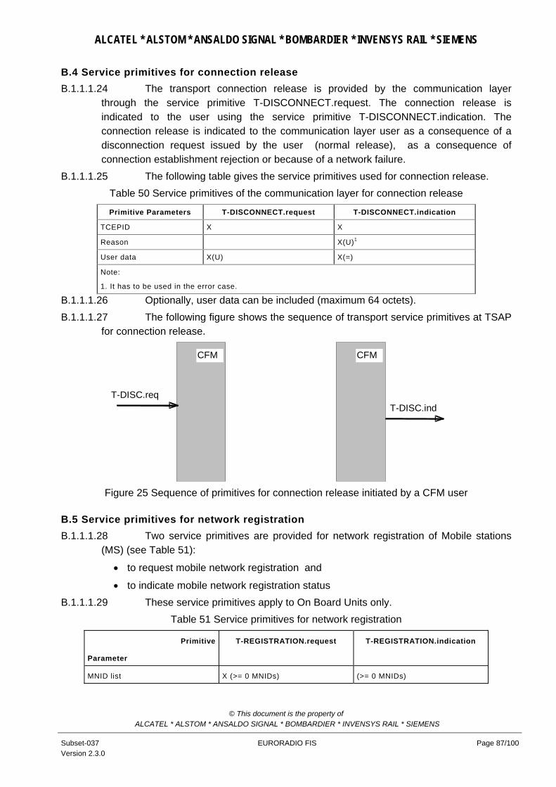
ALCATEL * ALSTOM * ANSALDO SIGNAL * BOMBARDIER * INVENSYS RAIL * SIEMENS
B.4 Service primitives for connection release B.1.1.1.24 The transport connection release is provided by the communication layer
through the service primitive T-DISCONNECT.request. The connection release is indicated to the user using the service primitive T-DISCONNECT.indication. The connection release is indicated to the communication layer user as a consequence of a disconnection request issued by the user (normal release), as a consequence of connection establishment rejection or because of a network failure.
B.1.1.1.25 The following table gives the service primitives used for connection release. Table 50 Service primitives of the communication layer for connection release
Primitive Parameters T-DISCONNECT.request T-DISCONNECT.indication
TCEPID X X
Reason X(U)1
User data X(U) X(=)
Note:
1. It has to be used in the error case.
B.1.1.1.26 Optionally, user data can be included (maximum 64 octets). B.1.1.1.27 The following figure shows the sequence of transport service primitives at TSAP
for connection release.
CFM CFM
T-DISC.reqT-DISC.ind
Figure 25 Sequence of primitives for connection release initiated by a CFM user
B.5 Service primitives for network registration B.1.1.1.28 Two service primitives are provided for network registration of Mobile stations
(MS) (see Table 51):
• to request mobile network registration and
• to indicate mobile network registration status B.1.1.1.29 These service primitives apply to On Board Units only.
Table 51 Service primitives for network registration
Primitive
Parameter
T-REGISTRATION.request T-REGISTRATION.indication
MNID list X (>= 0 MNIDs) (>= 0 MNIDs)
© This document is the property of ALCATEL * ALSTOM * ANSALDO SIGNAL * BOMBARDIER * INVENSYS RAIL * SIEMENS
Subset-037 Version 2.3.0
EURORADIO FIS Page 87/100

ALCATEL * ALSTOM * ANSALDO SIGNAL * BOMBARDIER * INVENSYS RAIL * SIEMENS
By means of the service primitive “T-REGISTRATION.request” the service user is able to request the registration of one or more mobile stations with one or more mobile networks.
B.1.1.1.30 MNID list is a list of mobile network IDs.
B.1.1.1.31 A Mobile network ID identifies the mobile network a local mobile station is requested to register with. The mobile network ID shall consist of the Mobile Country Code and the Mobile Network Code according to [ITU-T E.212].
B.1.1.1.32 The interpretation of the MNID list is matter of implementation. E.g.:
Empty :
All available mobile stations are requested to be registered using automatic network registration from GSM-R on-board radio equipment (see GSM 02.11).
One entry:
All available mobile stations are requested to be registered on network defined by the entry using manual network registration from GSM-R on-board radio equipment.
Two different entries (MNID#1, MNID#2):
The available mobile stations have to be split in two parts and to register first part on network defined by MNID #1 and second part on network defined by MNID #2.
In case not enough mobile stations are available to perform registration on both networks, registration shall be provided according to priority in the list : MNID # 1 shall be delivered first.
B.1.1.1.33 The status of registration with mobile networks is indicated by the service primitive “T-REGISTRATION.indication” to the service user. The service primitive contains a list of mobile network IDs, which are usable because mobile station(s) are registered with them.
B.1.1.1.34 NOTE: the association between MS and MNID in these service primitives is a local implementation matter.
B.1.1.1.35 The service user is not informed on how many mobile stations are available but receives only status of registered network which means implicitly that connection request on these networks can be issued or not.
B.1.1.1.36 If the indicated list of mobile network IDs is empty, the registration of mobile stations was not possible or the coverage has been lost.
B.1.1.1.37 The network registration indication can be given independently of a request. This feature allows indications after power-up or after loss of coverage. Any change on network registration can be indicated.
© This document is the property of ALCATEL * ALSTOM * ANSALDO SIGNAL * BOMBARDIER * INVENSYS RAIL * SIEMENS
Subset-037 Version 2.3.0
EURORADIO FIS Page 88/100

ALCATEL * ALSTOM * ANSALDO SIGNAL * BOMBARDIER * INVENSYS RAIL * SIEMENS
Annex C (Option) Safety Protocol Management C.1.1.1.1 The safety protocol management defines the configuration management needed
to handle the parameters of the safety protocol, and the supervision and diagnostics of the safety protocol. The main emphasis is placed on achieving technical interoperability between the on-board unit and the trackside unit with respect to the safety protocol management.
C.1.1.1.2 All details of the specification, which are implementation dependent like the generation, storage, and deletion of keys, or error logging are not covered by this specification.
C.1.1.1.3 If the safe connection has been established, the management SaPDUs can be exchanged.
C.1.1.1.4 The transfer of management SaPDUs is caused by internal management events. The Management SaPDUs allow the requested communication for the key management.
C.1.1.1.5 The timer Ttrans is applied to check the maximal acceptable delay of a management transaction. The timer Ttrans is set after transmission of the RQ SaPDU (by means of a T-DATA.request) and is stopped after receiving the related RP SaPDU (included in the T-DATA.indication). In the case of time-out, the pending transaction is cancelled, and the request is sent again. The timer Ttrans is fixed to 1minute.
C.1.1.1.6 In case of disconnection during the management transaction, the request will be repeated: the receiver of a RQ SaPDU will not establish the physical link and directly send the RP SaPDU: it will wait until a new safe link is established and the RQ SaPDU is received again before answering. An RP SaPDU must always be linked to an RQ SaPDU of the same session.
© This document is the property of ALCATEL * ALSTOM * ANSALDO SIGNAL * BOMBARDIER * INVENSYS RAIL * SIEMENS
Subset-037 Version 2.3.0
EURORADIO FIS Page 89/100

ALCATEL * ALSTOM * ANSALDO SIGNAL * BOMBARDIER * INVENSYS RAIL * SIEMENS
Responder
Initiator
T-DATA.ind
T-DATA.request
RQ SaPDU
T-DATA.req
T-DATA.ind
RP SaPDU
Internalmanagementevent
Internalmanagement
Internalmanagementevent
event
Set Ttrans
Stop Ttrans
Figure C-1 Time sequence of a management transaction
C.1Management SaPDUs C.1.1.1.7 The Management SaPDUs are used for exchanging messages for the key
management. The on-board equipment will receive the Management SaPDUs (messages for the key management), directly from its KMC.
C.1.1.1.8 For exchanging RP SaPDUs and RQ SaPDUs, it is necessary to establish first a safe connection (I&A dialogue). The structure of management SaPDUs is specified in Table 52.
Table 52 Structure of a Management SaPDU
Header
Identifier Sub-Type of Message Data MAC
1 octet 1 octet 1 octet variable 8 octets
C.1.1.1.9 The request management SaPDU (RQ) and response management SaPDU (RP) consist of the fields specified in Table 53.
© This document is the property of ALCATEL * ALSTOM * ANSALDO SIGNAL * BOMBARDIER * INVENSYS RAIL * SIEMENS
Subset-037 Version 2.3.0
EURORADIO FIS Page 90/100

ALCATEL * ALSTOM * ANSALDO SIGNAL * BOMBARDIER * INVENSYS RAIL * SIEMENS
Table 53 Structure of RQ and RP SaPDU
Octet Bit
8765 4321 Field 18
1 xxx. ....
000. .... 001. .... 010. .... 101. .... 110. ....
ETCS ID type of the SaPDU sender Radio in-fill unit RBC Engine Key management entity Reserved for Interlocking related entity Not required for Class 1
1 ...1 011.
...1 100.
Message Type Identifier: RQ
Message Type Identifier: RP
1 .... ...x Direction flag
2 xxxx xxxx Identifier
3 xxxx xxxx Sub-Type of Message
4
...
4+n-1
xxxx xxxx
...
xxxx xxxx
Data (1 octet ≤ length ≤ 1021octets): MANDATA.
4+n
...
4+n+7
xxxx xxxx
...
xxxx xxxx
MAC field (the MAC is computed according to the rules given in the peer entity and message origin authentication procedure).
C.1.1.1.10 The Identifier is arbitrarily chosen by the sender. The aim of this identifier is to make a link between a response and a request. The identifier will also be used in order to avoid a replay attack. Therefore, inside a session, the same identifier cannot be used twice.
C.1.1.1.11 This means, that, inside a session, no more than 256 exchanges can be carried out. The identifier can be "a sequence number" for example, but it is not required to do a check on the right "sequence" at the reception.
C.1.1.1.12 The sender can choose to use a one byte random number for identifying the messages; it must just guarantee that the same random number will not be used twice in the same session.
C.2 Error Handling C.1.1.1.13 Error type: Replay of a message (same message type, with same content when
another type was expected) Table 54 Sub-reasons for the error type 'failure in sequence integrity'
Reason Code
Sub-reason Code
Description Error handling action
18 The exact format of the messages is defined in the Unisig documents related to on-line key
management.
© This document is the property of ALCATEL * ALSTOM * ANSALDO SIGNAL * BOMBARDIER * INVENSYS RAIL * SIEMENS
Subset-037 Version 2.3.0
EURORADIO FIS Page 91/100

ALCATEL * ALSTOM * ANSALDO SIGNAL * BOMBARDIER * INVENSYS RAIL * SIEMENS
Reason Code
Sub-reason Code
Description Error handling action
5 5 Replay of management message exchanged between KMC and entity
Sa- REPORT.indication
5 6 Missing management message exchanged between KMC and entity
Sa- REPORT.indication
C.1.1.1.14 Error type: Time out at connection establishment or for management transaction.
Table 55 Sub-reasons for the error type 'failure in connection monitoring'
Reason Code
Sub-reason Code
Description Error handling action
7 4 Time out of Ttrans without receiving the correct RP SaPDU
Sa-REPORT.indication
C.1.1.1.15 Error type: Failure in the sequence of SaPDUs during connection set up and during management functions, respectively.
Table 56 Sub-reasons for the error type 'failure in sequence of the SaPDUs'
Reason Code
Sub-reason Code
Description Error handling action
9 4 Transmission of RQ SaPDU but a message different from RP SaPDU is obtained.
Sa-REPORT.indication
C.1.1.1.16 Error type: SaPDU too short, i.e. fields are missing Table 57 Sub-reasons for the error type ' SaPDU too short, i.e. fields are missing'
Reason Code
Sub-reason Code
Description Error handling action
10 6 RQ SaPDU too short Sa-REPORT.indication, rejection of RQ SaPDU
10 7 RP SaPDU too short Sa-REPORT.indication, rejection of RP SaPDU
© This document is the property of ALCATEL * ALSTOM * ANSALDO SIGNAL * BOMBARDIER * INVENSYS RAIL * SIEMENS
Subset-037 Version 2.3.0
EURORADIO FIS Page 92/100

ALCATEL * ALSTOM * ANSALDO SIGNAL * BOMBARDIER * INVENSYS RAIL * SIEMENS
Annex D (Informative) Applicability conditions of ISO/IEC 7776 (1995) Notes:
1. Only DTE to remote DTE will be considered since this is the case applicable to Euroradio 2. “Not applicable” means this case is not possible for Euroradio 3. “shall be used” and “shall not be used” indicate the application conditions for Euroradio 4. “Optional” means this feature can be implemented or not; if implemented it shall be
compliant with the specification
Section Application conditions
Foreword Annex A (conformance) shall not be used
Introduction "Protocol Implementation Conformance Statement" shall not be used
§ 1 Scope Shall be used
Only the following features/options shall be used
• DTE/DTE communication
• Start/Stop transmission
• Extended (mod 128) operation
• Single link procedure
Bilateral agreements means: “General agreement for all EuroRadio implementations is made by this application conditions”
Clause 7 (conformance) shall not be used
§ 2 Normative references Shall be used
ISO/IEC 7478, X.25, ISO/IEC 9646—1,2:1994 ISO/IEC 646 are not applicable
§ 3 Frame structure Shall be used. Table 1 (modulo 8) shall not be used
§ 3.1 Flag sequence Shall be used
§3.2 Address field Shall be used
§ 3.3 Control field Shall be used. Basic (modulo 8) operation shall not be used
§3.4 Information field Shall be used
§ 3.5.1
Transparency Synchronous transmission
Not Applicable
§ 3.5.2
Transparency Start/stop transmission
Shall be used. Control-escape transparency only shall be used
§3.5.2.1
Seven-bit data path transparency
Shall not be used
§ 3.5.2.2
Control-escape transparency
Shall be used
© This document is the property of ALCATEL * ALSTOM * ANSALDO SIGNAL * BOMBARDIER * INVENSYS RAIL * SIEMENS
Subset-037 Version 2.3.0
EURORADIO FIS Page 93/100

ALCATEL * ALSTOM * ANSALDO SIGNAL * BOMBARDIER * INVENSYS RAIL * SIEMENS
Section Application conditions
§ 3.5.2.3
Extended transparency
Shall not be used
§ 3.5.2.3.1
Flow-control transparency
Shall not be used
§ 3.5.2.3.2
Control-character octet transparency
Shall not be used
§ 3.6 Frame check sequence (FCS) field
Shall be used
§ 3.7.1
Order of bit transmission
Shall be used
The order of transmitting bits within each octet in the information field is to send the least significant bit first.
§ 3.7.2
Start/stop transmission
Shall be used
§ 3.8.1
Invalid frames Synchronous transmission
Not Applicable
§ 3.8.2
Invalid frames Start/stop transmission
Shall be used
§ 3.9.1
Frame abortion Synchronous transmission
Not Applicable
§ 3.9.2
Frame abortion Start/stop transmission
Shall be used
§ 3.10.1
Interframe time fill Synchronous transmission
Not Applicable
§ 3.10.2
Interframe time fill Start/stop transmission
Shall be used. Flags shall not be used as interframe time fill . [FIS 8.2.2.7l)]
§ 3.11.1
Data link channel states Synchronous transmission
Not Applicable
§ 3.11.2.1
Data link channel states Start/stop transmission Active channel state
Channel state shall not be used. Flags shall not be used as interframe time fill in. [FIS 8.2.2.7l)]
§ 3.11.2.2
Data link channel states Start/stop transmission Idle channel state
Channel state shall not be used. Timer T5 shall not be used
§ 4.1.1
Control field formats
Shall be used. Table 3 (Modulo 8 operation) shall not be used
§ 4.1.1.1
Information transfer format ⎯ I
Shall be used
© This document is the property of ALCATEL * ALSTOM * ANSALDO SIGNAL * BOMBARDIER * INVENSYS RAIL * SIEMENS
Subset-037 Version 2.3.0
EURORADIO FIS Page 94/100
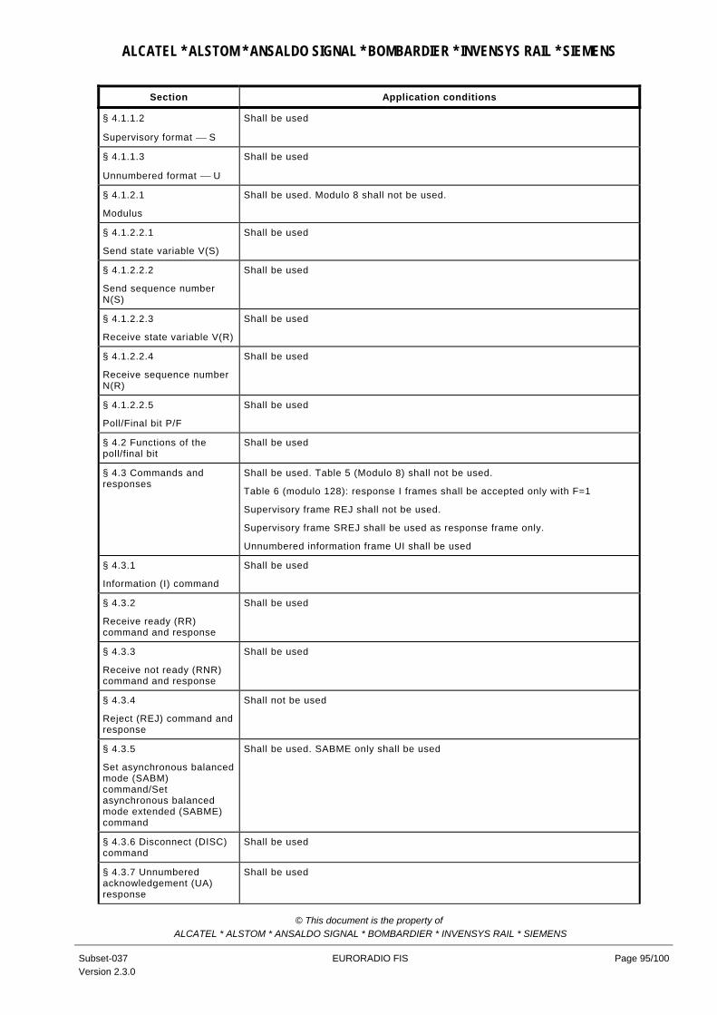
ALCATEL * ALSTOM * ANSALDO SIGNAL * BOMBARDIER * INVENSYS RAIL * SIEMENS
Section Application conditions
§ 4.1.1.2
Supervisory format ⎯ S
Shall be used
§ 4.1.1.3
Unnumbered format ⎯ U
Shall be used
§ 4.1.2.1
Modulus
Shall be used. Modulo 8 shall not be used.
§ 4.1.2.2.1
Send state variable V(S)
Shall be used
§ 4.1.2.2.2
Send sequence number N(S)
Shall be used
§ 4.1.2.2.3
Receive state variable V(R)
Shall be used
§ 4.1.2.2.4
Receive sequence number N(R)
Shall be used
§ 4.1.2.2.5
Poll/Final bit P/F
Shall be used
§ 4.2 Functions of the poll/final bit
Shall be used
§ 4.3 Commands and responses
Shall be used. Table 5 (Modulo 8) shall not be used.
Table 6 (modulo 128): response I frames shall be accepted only with F=1
Supervisory frame REJ shall not be used.
Supervisory frame SREJ shall be used as response frame only.
Unnumbered information frame UI shall be used
§ 4.3.1
Information (I) command
Shall be used
§ 4.3.2
Receive ready (RR) command and response
Shall be used
§ 4.3.3
Receive not ready (RNR) command and response
Shall be used
§ 4.3.4
Reject (REJ) command and response
Shall not be used
§ 4.3.5
Set asynchronous balanced mode (SABM) command/Set asynchronous balanced mode extended (SABME) command
Shall be used. SABME only shall be used
§ 4.3.6 Disconnect (DISC) command
Shall be used
§ 4.3.7 Unnumbered acknowledgement (UA) response
Shall be used
© This document is the property of ALCATEL * ALSTOM * ANSALDO SIGNAL * BOMBARDIER * INVENSYS RAIL * SIEMENS
Subset-037 Version 2.3.0
EURORADIO FIS Page 95/100

ALCATEL * ALSTOM * ANSALDO SIGNAL * BOMBARDIER * INVENSYS RAIL * SIEMENS
Section Application conditions
§ 4.3.8
Disconnected mode (DM) response
Shall be used. An ”unsolicited DM” shall not be used. . [FIS 8.2.2.7d)]
§ 4.3.9 Frame reject (FRMR) response
Shall be used.
REJ shall be identified as “not implemented”.
SREJ and UI shall be identified as “implemented”.
Table 7 (modulo 8) shall not be used.
§ 4.4.1 Busy condition Shall be used
§ 4.4.2 N(S) sequence error
Shall be used .
The first sentence (The information field….shall be discarded) shall not be used.
The last sentence shall be used only for the means specified in 4.4.2.1 (Checkpoint recovery) and 4.4.2.3 (Timeout recovery).
§ 4.4.2.1
Checkpoint recovery
Shall be used
§ 4.4.2.2
REJ recovery
Shall not be used. SREJ recovery shall be used instead.
§ 4.4.2.3
Time-out recovery
Shall be used
§ 4.4.3 Invalid frame condition
Shall be used
§ 4.4.4 Frame rejection condition
Shall be used
In the case of FRMR reject condition; link reset shall not be used. The receiver of FRMR shall send a DISC frame as a response. [FIS 8.2.2.7e)]
§ 5.1 Procedure for addressing
Shall be used. Single link operation (SLP) only shall be used.
The end system initiating the establishment of the B/Bm channel is considered to be the “calling end system”. The calling end system plays the DTE role and the called system plays the DCE role in respect to addressing. [FIS 8.2.2.7i)]
§ 5.2 Procedure for the use of the P/F bit
Shall be used
§ 5.3.1
Procedures for link set-up and disconnection
Link set-up
Shall be used.
The calling end system shall initiate link set-up. [FIS 8.2.2.7j)]
SABME only shall be used.
The DTE shall never re-initiate link set-up.
§ 5.3.2
Information transfer phase
Shall be used. Timer T4 is optional
In the information transfer phase a SABME command shall not be sent, because link resetting is not allowed (see §5.3.1)
When receiving a SABME command while in the information transfer phase, the DTE shall send a DISC command and then initiate the release of the B/Bm channel.
For backward compatibility response I frames shall be accepted with F=1 (see [ISO 7809] section 5.4.2.1 and 5.4.2.2). [FIS 8.2.2.9]
§ 5.3.3 Link disconnection Shall be used.
Receiving of SABME is not applicable.
Optionally, the sender of the DISC can initiate the release of the B/Bm channel.
© This document is the property of ALCATEL * ALSTOM * ANSALDO SIGNAL * BOMBARDIER * INVENSYS RAIL * SIEMENS
Subset-037 Version 2.3.0
EURORADIO FIS Page 96/100

ALCATEL * ALSTOM * ANSALDO SIGNAL * BOMBARDIER * INVENSYS RAIL * SIEMENS
Section Application conditions
§ 5.3.4 Disconnected phase
Shall be used.
Both DTE shall never re-initiate link set-up.
The last two clauses shall not be used.
§ 5.3.5
Collision of unnumbered commands
Shall be used.
§ 5.3.6
Collision of DM response with SABM/SABME or DISC command
Not Applicable
An ”unsolicited DM” shall not be used. . [FIS 8.2.2.7d)]
§ 5.3.7
Collision of DM responses
Not Applicable..
An ”unsolicited DM” shall not be used. . [FIS 8.2.2.7d)]
§ 5.4 Procedures for information transfer
Shall be used. Modulo 8 shall not be used.
§ 5.4.1
Sending I frames
Shall be used
§ 5.4.2
Receiving an I frame
Shall be used.
The acknowledgement of the received I- frame shall be sent as soon as possible, in any case not later than T2.
§ 5.4.3
Reception of invalid frames
Shall be used
§ 5.4.4 Reception of out-of-sequence frames
Shall not be used. SREJ recovery action shall be used instead.
§ 5.4.5
Receiving acknowledgment
Shall be used
§ 5.4.6
Receiving a REJ frame
Not Applicable. REJ frame shall not be used
A received REJ shall result in a FRMR.
§ 5.4.7
Receiving an RNR frame
Shall be used
REJ shall not be used
§ 5.4.8
DTE busy condition
Shall be used
REJ shall not be used
§ 5.4.9
Waiting acknowledgement
Shall be used
REJ shall not be used. SREJ shall be used instead
§ 5.5 Conditions for link resetting or link re-initialization (link set-up)
Shall be used. Link resetting procedures (5.6.1) shall not be used.
§ 5.6.1
Procedure for link resetting
Link reset
Shall not be used.
§ 5.6.2
Procedure for link resetting
Request for link reset
Shall be used.
Link resetting procedures (5.6.1) shall not be used.
§ 5.7.1.1 Timer T1 Shall be used
Table 40 ”Layer2 configuration parameters“ contains the value(s)
© This document is the property of ALCATEL * ALSTOM * ANSALDO SIGNAL * BOMBARDIER * INVENSYS RAIL * SIEMENS
Subset-037 Version 2.3.0
EURORADIO FIS Page 97/100

ALCATEL * ALSTOM * ANSALDO SIGNAL * BOMBARDIER * INVENSYS RAIL * SIEMENS
Section Application conditions
§ 5.7.1.2 Timer T2 Shall be used
§ 5.7.1.3 Timer T3 Optional
§ 5.7.1.4 Parameter T4 Optional
§ 5.7.1.5 Parameter T5 Not Used
§ 5.7.2 Maximum number of transmissions N2
Shall be used.
See note in ER FIS §8.3.2.2
§ 5.7.3 Maximum number of bits in an I frame N1
Shall be used
§ 5.7.4 Maximum number of outstanding I frames k
Shall be used
§ 6 Multilink procedure Not Used
§ 7.1 Static Conformance Conformance to chapter 7 is not required.
Subset 092-1 contains the conformance requirements to ER FIS
§ 7.2 Dynamic Conformance
Conformance to chapter 7 is not required.
Subset 092-1 contains the conformance requirements to ER FIS
Annex B Informative
© This document is the property of ALCATEL * ALSTOM * ANSALDO SIGNAL * BOMBARDIER * INVENSYS RAIL * SIEMENS
Subset-037 Version 2.3.0
EURORADIO FIS Page 98/100

ALCATEL * ALSTOM * ANSALDO SIGNAL * BOMBARDIER * INVENSYS RAIL * SIEMENS
Annex E (Informative) Version interoperability Confirmed interoperability issues of EuroRadio implementations based on released versions are listed in this Annex.
E.1 Subset-037 version 2.0.0 and version 2.2.5
Interoperability is not possible.
Nr ER FIS 200 section
Problem and changes Comments
1. 7.2.2.1.1
clause 24;
7.2.2.1.1
clause 42
The length of string length is part of the input fields for MAC computation and MAC check.
The length itself was not specified in ER FIS 2.0.0. and is specified as 2 octets in ER FIS 2.2.5
different interpretations are possible in v2.0.0; therefore interoperability can only be guaranteed if the implementation conforms to vn2.2.5.
2. 7.2.2.1.2
clause 50
The ETY field should be part of the text strings for peer entity authentication and MAC computation/MAC check.
The ETY field was not inserted in procedure3 of ER FIS 2.0.0. and is inserted in procedure3 of ER FIS 2.2.5
different interpretations are possible in v2.0.0; therefore interoperability can only be guaranteed if the implementation conforms to vn2.2.5.
3. 8.2.2
clause 31
Collision of HDLC SABME should be avoided: only the calling party should send a SABME.
Calling and called party are allowed to send SABME according to ER FIS 2.0.0. The restriction to calling party is specified in ER FIS 2.2.5
4. 8.2.2. A recommendation about interframe time fill-in should be given.
Interframe time fill-in was not specified in ER FIS 2.0.0. and is recommended as ‘Mark’ in ER FIS 2.2.5
Interoperability problems should not exist: it is only a recommendation
5. 8.2.4.6 The ETCS ID type of RIU and RBC was the same one in ER FIS 2.0.0. and is different in ER FIS 2.2.5
6. 8.3.1 Handling of mobile network ID should be specified at the interface to the application to be able to handle transitions between networks.
It was considered as internal task of CFM and therefore not specified in ER FIS 2.0.0. and is specified in ER FIS 2.2.5
Network registration is not supported by SRS 2.2.2: i.e. this parameter will not be used.
© This document is the property of ALCATEL * ALSTOM * ANSALDO SIGNAL * BOMBARDIER * INVENSYS RAIL * SIEMENS
Subset-037 Version 2.3.0
EURORADIO FIS Page 99/100

ALCATEL * ALSTOM * ANSALDO SIGNAL * BOMBARDIER * INVENSYS RAIL * SIEMENS
E.2 Subset-037 version 2.2.5 and latest version
Nr ER FIS 225 section
Problem and changes Comments
1. 2.2.5 section 5.7 (new);
section B.5 (new);
8.3.1
[Subset-026] §3.5.6 specifies registration with mobile networks.
The solution specified in ER FIS 2.2.5 is not suitable.
The respective sections of ER FIS are modified:
Service primitives for network registration
Handling of mobile network ID
Interoperability problems may exist at GSM-R network border crossing.
2. 8.2.2.6 Different interpretations of the behaviour of Option 8 are possible in version 2.2.5.
The latest version of ER FIS clarifies the use of response I frames.
Interoperability of the implementation should be checked
3. 8.2.2 Option 3.2 (multi-selective reject) is used by all ER FIS versions, but different interpretations are possible.
The latest version of ER FIS clarifies the use of Option 3.2.
No known problems have been reported so far.
4. 8.3.2.2. Table 39 The recommended values of layer 2 configuration parameters length are modified in latest version of ER FIS.
These parameters will not influence interoperability.
© This document is the property of ALCATEL * ALSTOM * ANSALDO SIGNAL * BOMBARDIER * INVENSYS RAIL * SIEMENS
Subset-037 Version 2.3.0
EURORADIO FIS Page 100/100


