Embed Size (px)
Citation preview

1082 IEEE TRANSACTIONS ON ENERGY CONVERSION, VOL. 23, NO. 4, DECEMBER 2008
A Multiagent-System-Based Intelligent ReferenceGovernor for Multiobjective Optimal Power
Plant OperationJin S. Heo and Kwang Y. Lee, Life Fellow, IEEE
Abstract—A large-scale power plant requires optimal set points,namely references, in several control loops for multiobjective op-timal operation. In a 600-MW oil-fired drum-type boiler powerunit, the set points considered are for the main steam pressure andreheater/superheater steam temperatures. The set points shouldbe mapped with the varying unit load demand and satisfy the con-flicting requirements in power plant operation. In practice, theset points are obtained using fixed nonlinear functions in the unitmaster control in a plant, which are designed for the single objec-tive of load tracking with heat balance. However, it does not allowfor process optimization under the multitude of conflicting objec-tives, which may be newly introduced and different from the initialdesign objective. This paper presents a methodology, multiagent-system-based intelligent reference governor (MAS-IRG), to realizethe optimal mapping by searching for the best solution to the mul-tiobjective optimization problem that tackles conflicting require-ments. In searching for the optimal set points, a heuristic opti-mization tool, particle swarm optimization, is utilized to solve themultiobjective optimization problem. The IRG is designed basedon the proposed MAS to operate at a higher level of automation,to execute asynchronous computations, and to reduce the compu-tational complexity. The approach provides the means to specifyoptimal set points for controllers under a diverse operating scenar-ios online.
Index Terms—Multiagent system (MAS), multiobjective opti-mization, optimal set point scheduling, particle swarm optimiza-tion (PSO), power plant control, reference governor, unit mastercontrol.
I. INTRODUCTION
WHILE the demand in power is increasing, power plantsare getting larger and more complex to run. In order to
achieve an optimal operation, optimal set points, namely ref-erences, are required for the power plant control system. Inpractice, the set points are obtained by using fixed nonlinearfunctions in the unit master control in a plant, which are de-signed for the single objective of load tracking with heat balance.However, it does not allow for process optimization under themultitude of conflicting objectives, which may be newly intro-duced and different from the initial design objective. In general,the set points need to be scheduled by considering conflictingoperational requirements such as minimization of load-tracking
Manuscript received March 7, 2006; revised January 24, 2007. Current ver-sion published November 21, 2008. Paper no. TEC-00069-2006.
The authors are with the Department of Electrical & Computer Engineer-ing, Baylor University, Waco, TX 76798 USA (e-mail: [email protected];[email protected]).
Color versions of one or more of the figures in this paper are available onlineat http://ieeexplore.ieee.org.
Digital Object Identifier 10.1109/TEC.2008.2001459
error, minimization of fuel consumption and heat loss rate, max-imization of duty life, minimization of pollutant emissions, etc.These conflicting requirements can be tackled by a multiobjec-tive optimization problem in generating optimal set points.
However, the multiobjective optimization problem for powerplant operation lies not only in the generation of optimal setpoints but also in the design of architecture for control systems.Standard optimization methods for a large-scale multiple-inputmultiple-output (MIMO) nonlinear system result in a heavycomputational burden if they are used for generating the op-timal set points. Moreover, traditional optimization techniquesmay often become computationally unattractive or even unac-ceptable [1]. Control system architectures have been consideredto reduce the computational complexity and manage the hugeamount of distributed data and coupling problems among manysubsystems.
Recently, there has been a growing interest in heuristic opti-mization techniques, genetic algorithm (GA) and particle swarmoptimization (PSO), as variations of evolutionary algorithm(EA). It has been shown that it can provide quality solutionsand fast convergences in many applications [4]–[13]. However,in previous studies [3]–[5], the performance of GA is lowerthan PSO techniques for the solution quality, convergence rate,and computational complexity. On the other hand, the study ofmultiagent systems (MASs) has become an important aspectof power system architecture in order to deal successfully withthe problems of complexity and large-scale distributed systems.Each agent system has special functions in solving the dis-tributed systems. In addition, in the MAS, the agents can worktogether to solve problems, which are beyond the capabilities orknowledge of an individual agent [26].
As an optimal set-point generator for optimal control actions,the reference governor has been developed using a goal pro-gramming (GP) method, GA, and PSO for small-scale powerplants [2]–[5]. Moreover, the comparison among the variationsof PSO has been investigated within the reference governor [4].There have been a few researches for reference governor inother application areas. A reference governor was designed fora predictive control to provide the references in the predictionhorizon [14]. The reference governor was also designed for sys-tems with state and control constraints [15].
The previous studies [4], [5] presented the concept of the ref-erence governor for a small-scale power plant that was a third-order nonlinear MIMO, fossil-fuel power plant model. For thesmall-scale power plant, the implementation of reference gov-ernor did not require the MAS concept to reduce computational
0885-8969/$25.00 © 2008 IEEE
Authorized licensed use limited to: Baylor University. Downloaded on January 22, 2010 at 15:20 from IEEE Xplore. Restrictions apply.

HEO AND LEE: MAS-IRG FOR MULTIOBJECTIVE OPTIMAL POWER PLANT OPERATION 1083
Fig. 1. Fixed nonlinear mapping for the references.
complexity and distributed and asynchronous problems. How-ever, as the scale of the systems increases, control systems re-quire a new framework to reduce the computational complexityand manage the huge amount of distributed data. Thus, the ref-erence governor for a large-scale power plant is required to bedeveloped based on the concept of MAS proposed in [28]. Thefundamental concept of MAS is the cooperation of distributedmultiple agents performing their jobs independently. Many ap-plications of MASs or agent-oriented systems have been pre-sented in control and monitoring systems to overcome the prob-lems associated with large-scale distributed systems [21]–[30].
Although many studies have been done on the reference gov-ernor, it is developed for small-scale power plants. Design pro-cedures for the reference governor are unconvincing for a large-scale power plant. Moreover, although there are many appli-cations of MAS for distributed systems, little information isavailable for control system design of power plants. The pri-mary focus of this paper is on the development of an intelligentreference governor (IRG) for multiobjective power plant oper-ation with the proposed architectures of a single agent and anMAS. The multiobjective optimal power plant operation will beachieved by minimizing load-tracking error, fuel consumption,heat loss rate and pollutant emission, and maximizing duty lifeon equipment.
In a 600-MW oil-fired drum-type boiler power unit, theset points considered are for the main steam pressure and re-heater/superheater steam temperatures. The set points should bemapped by varying the unit load demand (ULD), and they shouldsatisfy the conflicting operation requirements of the power plant.In general, the set points obtained by using a fixed nonlinearfunction cannot provide optimal power plant operation. Fig. 1shows the fixed nonlinear functions. The set points are obtainedusing fixed nonlinear functions that are designed for the singleobjective of load tracking with heat balance. However, it doesnot allow for process optimization under the newly introducedmultitude of conflicting objectives, which are different from theinitial design objective.
This paper presents a methodology, MAS-based IRG(MAS-IRG), to realize the optimal mapping by searching forthe best solution to the multiobjective optimization problemthat tackles the conflicting requirements. In searching for theoptimal set points, a heuristic optimization tool PSO is utilizedfor the multiobjective optimization. The IRG is designed basedon the proposed MAS to operate at a higher level of automation,execute asynchronous computations, and reduce the computa-tional complexity. The approach provides the means to specify
optimal set points for controllers under a diverse operating sce-narios online.
The proposed MAS-IRG will be one of the functions in theMAS-based intelligent control (MAS-IC) that has several func-tions such as identification, fault-diagnosis, and modeling thatprovide efficient way to control locally and globally, and accom-modate and overcome the complexity of large-scale distributedpower systems. The MAS-IRG is based on the initial concept ofMAS in [28], utilizes the steady-state model developed in [29],and can be used for fault-diagnostics and accommodation pro-posed in [30].
Following Section I, the power plant is described in Section II.Section III shows MAS. Section IV describes MAS-IRG.Section V shows simulation results to demonstrate the feasibil-ity of the proposed approach and the final section draws someconclusions.
II. POWER PLANT
The power plant under consideration is a 600-MW oil-fireddrum-type boiler–turbine–generator unit [17] shown in Fig. 2.It is a balanced draft, controlled recirculation drum boiler capa-ble of delivering 4.2 × 10⁶ lb/h of steam at a pressure of 2600psig and at 1005 F. Six recirculation pumps supply the requiredrecirculation flow to provide sufficient flow for full-load oper-ation. Two forced draft fans supply the primary air, and twoinduced draft fans are controlled to maintain a furnace pressureat a desired preset value. Two condensate pumps and a com-bined booster and main boiler feedpumps handle the feedwaterflow.
The turbine is a tandem compound triple pressure steam tur-bine. It consists of three parts: a high-pressure turbine, an inter-mediate pressure turbine, and low twin pressure turbines rotat-ing on a common shaft at a rated speed of 3600 r/min and at anexhausting pressure of 2-in Hg absolute. The generator is cou-pled with the turbine and features a 685 600 kV·A, three-phase,60 Hz, 22 kV supply, with a power factor of 0.90 lagging.
There are many power plant models developed over theyears [16]. The developed model represents an extension ofsome existing models [19], [20] in two primary areas. First,the condensate and feedwater side dynamics have been mod-eled, and second, the electrical prime movers that run fans andpumps and their dependence upon driving voltage and frequencyhave been modeled. The power plant model developed for the600-MW unit [17] is validated in MATLAB environment [18].There are four major modules consisting of 33 subsystems.Each I/O of subsystems is evaluated with data provided in thereference [17]. The model has 23 state variables and 12 controlvalves (u1 , u2 , . . . , u12) associated with physical processes [18].In Fig. 2, the control valves are named as following: u1 : fuelflow, u2 : gas recirculation, u3 : induced draft fan, u4 : forceddraft fan, u5 : combustor gun (burner) tilt, u6 : superheater sprayflow, u7 : reheater spray flow, u8 : governor control valve, u9 :intercept valve, u10 : deaerator valve, u11 : feedwater valve, andu12 : feedpump turbine flow.
The set points are utilized at the distributed controllers. Themodel is grouped into four main modules, which are boiler
Authorized licensed use limited to: Baylor University. Downloaded on January 22, 2010 at 15:20 from IEEE Xplore. Restrictions apply.

1084 IEEE TRANSACTIONS ON ENERGY CONVERSION, VOL. 23, NO. 4, DECEMBER 2008
Fig. 2. Large-scale power plant model and MAS.
system, turbine–generator system, condenser system, and feed-water system [19]. The proposed MAS-IRG is one of the func-tional systems based on the MAS that is interconnected withthe 31 subdivided and distributed subsystems that are compo-nents of the four main modules. Fig. 2 shows the large-scaledistributed thermal power plant model and MAS. Most blocksare subsystems represented by the model. The proposed schemewill be applicable to other types of plants, including nuclear andfuel cell plants.
III. MULTIAGENT SYSTEM
An agent is a computer software program that is autonomousand situated in some distributed environments in order to meetits design objectives. Since the agents are faced with differentenvironments, they are designed differently and properly for thegiven environment. Moreover, the agent is intelligent becauseit is reactive, proactive, social, flexible, and robust. In a large-scale distributed complex system, the agent’s autonomous andintelligent properties can reduce the complexity by reducing thecoupling problems between the subsystems. Furthermore, theproactive, reactive, and robust properties can be well suited forapplications in a dynamic and unreliable situation [26], [27].
In order to design the control systems, design of architecturefor a single agent and an organization for MAS are requiredin advance. First, the architecture of a single agent is shownin Fig. 3. Since the agent is situated in an environment that isthe power plant, it needs a perceptor and an effecter to act andreact. First, the sensed raw data are processed and mapped into ascenario, and then, an objective, which is a subgoal, is initializedunder the situation to achieve the main goal that is the optimaloperation. The initial objective is sent to other agents throughthe communicator for eliminating redundancy and conveying themission of the agent to others. After confirming the objective,
Fig. 3. Single agent architecture.
the best plan is chosen for the objective (subgoal) in the decisionmaking. Depending on the plan, an algorithm module is selectedto launch the plan. Finally, the action made by the algorithmmodule effects through the effecter into the environment. Mostdecisions are made in the decision-making process, which islike in a human brain [21], [22].
An MAS can be defined as a loosely coupled network (or-ganization) of problem solvers (agents), which interact to solveproblems that are beyond the individual capabilities or knowl-edge of each problem solver (agent). In order to perform thecooperative works, it is presented to build multiple hierarchicalstructures for the MAS organization, as shown in Fig. 4. Theorganization has low level, middle level, and high level, and anagent in each level has a specific role in the society so that thereis a conceptual idea of supervision for processing the tasks. Inthis paper, the high-level agents are the task delegation and in-terface agents, the middle-level agents are the mediate and mon-itoring agents, and the low-level agents are intelligent agents.
Authorized licensed use limited to: Baylor University. Downloaded on January 22, 2010 at 15:20 from IEEE Xplore. Restrictions apply.

HEO AND LEE: MAS-IRG FOR MULTIOBJECTIVE OPTIMAL POWER PLANT OPERATION 1085
Fig. 4. Organization of MAS.
Fig. 5. Composition of MAS-ICS for 600-MW power plant.
The hierarchical structure that has three levels gives advantagesfor dynamic organization and autonomous systems. Moreover,the idea of multiple hierarchical structures is well suited forlarge-scale distributed systems [25], [26]. Although there aremultiple hierarchical structures, each hierarchical structure hasa different formation from others because the structures are con-structed to fit for controlling real physical subsystems so thatthe organization is better optimized for a given power plant sys-tem [28]–[30]. Fig. 5 shows the composition of MAS-ICS forthe 600-MW power plant.
With the proposed structure of a single agent and the architec-ture of MAS, the MAS is implemented for the control systemsin the simulation environment. The agents are programs thatare distributed in high-performance computers. The structure ofthe program is built upon the proposed single-agent structure.Fig. 6 shows an example for one of the agent programs. Theexample shows the offline modeling agent that is an agent inthe intelligent identification system cluster. Since the powerplant simulators recommend the use of distributed computationusing PCs or workstations [32], the communication of MAS isdeveloped by using the following proposed scheme. The agents
Fig. 6. Example of one agent in the intelligent identification system cluster.
Fig. 7. Message communication in MAS.
Fig. 8. Task delegation and reconfiguration agents.
are communicating with each other though the Central MessageBoard (CMB) that is managed by a server computer. Fig. 7shows the message communication in MAS. The proposedcommunication protocol based on Transmission Control Pro-tocol (TCP)/IP is designed to provide security, restoration, andstatus of agents. One of the agents in the clusters keeps checkingthe CMB and lets receiving agent know that the information hasarrived. In order to communicate, all agents are unified by theproposed CMB. The TCP/IP supports the guaranty of delivery.The task delegation agent and reconfiguration agents that are themanaging layer agents proceed by observing the CMB and thestatus of agents, respectively. Fig. 8 shows how the task delega-tion agent manage the task flow and the reconfiguration agents
Authorized licensed use limited to: Baylor University. Downloaded on January 22, 2010 at 15:20 from IEEE Xplore. Restrictions apply.

1086 IEEE TRANSACTIONS ON ENERGY CONVERSION, VOL. 23, NO. 4, DECEMBER 2008
Fig. 9. Control structure of coordinated control.
coordinate the tasks. With the earlier proposed methodologies ofMAS, MAS-IRG will be developed in detail in the next section.
IV. MULTIAGENT-SYSTEM-BASED INTELLIGENT
REFERENCE GOVERNOR
A. Overall Control Structure
There has been several control strategies for the power plant:boiler-following control, turbine-following control, and coordi-nated boiler–turbine control strategies [31]. In order to make thecontrol system more response to load changes stable and faster,this paper uses the coordinated control scheme, which requiresreferences (or set points) for power demand (Ed ), main steampressure demand (Pd ), reheater temperature demand (RTd ), andsuperheater temperature demand (STd ). The control structure ofthe coordinated control is shown in Fig. 9, where the distributedcontrollers are developed in three main modules: MAS-IRG,feedforward controllers, and feedback controllers. The multiob-jective optimization is performed in the MAS-IRG. The resultsof the multiobjective optimization are the set points for thepower, pressure, and temperatures (Ed, Pd,RTd, STd) for thefeedforward and feedback controllers. The outputs of the twocontrollers are added to become input to the power plant. Theoutput of the power plant is fed back to the feedback controller,which regulates the output variations due to load disturbancesand compensates for the variations in the load demand.
The essence of the MAS-IRG in the coordinated control isto design the optimal mappings from the ULD, Euld , to the setpoints Ed, Pd,RTd , and STd :
SPE : (Euld , t) → (Ed, t)
SPP : (Euld , t) → (Pd, t)
SPRT : (Euld , t) → (RTd, t)
SPST : (Euld , t) → (STd, t)
which will be used to transform any ULD pattern (Euld , t) intooptimal set-point trajectories for the power (Ed, t), pressure(Pd, t), reheater temperature (RTd, t), and superheater temper-ature (STd, t) control loops.
The set-point mappings SP are designed by solving a multi-objective optimization problem that takes into account the speci-fied operation objectives and the steady-state model of the plant.The MAS-IRG performs the design process in three steps (seeFig. 10).
Fig. 10. Configuration of MAS-IRG.
1) Determination of the feasibility regions (Ω1 ,Ω2 , . . . ,Ω12)for the decision variables (u1 , u2 , . . . , u12).
2) Solution of the multiobjective optimization problem tofind optimal steady-state control signals (u∗
1 , u∗2 , . . . , u
∗12).
3) Calculation of the set points (Ed, Pd,RTd, STd) throughevaluation of the steady-state model of the unit.
The decision variables are candidate steady-state control in-puts for the control valves u1 , u2 , . . . , u12 , which are shown inFig. 2.
B. Implementation of MAS-IRG
The MAS-IRG realizes the optimal mapping between setpoints and varying ULD by searching for the best solution to themultiobjective optimization problem. The set points are consid-ered for the main steam pressure and reheater/superheater steamtemperatures in the power unit. The optimal set points are deter-mined by solving the multiobjective optimization problem withconflicting requirements such as load following, fuel conserva-tion, heat loss rate, life extension of equipments, reducing pollu-tion, etc. The composition of MAS for the power plant is shownin Fig. 5. Although all agents are connected with the network, thereference governor cluster, which is made up of a set-point gen-eration agent and a steady-state model agent, performs mainlyfor the MAS-IRG. However, the reference governor cluster willcooperate with the monitoring system, knowledge processingsystem, and reinforcement system clusters to obtain better per-formances. An operator will command and monitor the prefer-ence and status through the interface agent to/from the referencegovernor delegation agent who has all access for the MAS-IRG.
1) Feasibility Regions of Control Inputs: In order to realizethe MAS-IRG, first, all feasible operating points, which satisfyall imposed constraints, need to be found using the online perfor-mance monitoring agent and virtual simulation agent. The vir-tual simulation agent simulates the power output responses withvarious set-point conditions. When system response is in steadystate, the constant control inputs and static power, pressure, andtemperature outputs form pairs of operating points, where theadmissible power outputs can be obtained within an appropri-ate steam pressure and reheater/superheater temperature ranges.Fig. 11 shows the power output responses with different steampressure values for the 450-MW power set point. The figureshows that the same power output (450 MW) can be obtained inthe steady state with different steam pressure within the rangefrom 1900 to 2900 psia. Similarly, when power set point isfixed at 600 MW that is nominal power, the admissible pressurevalues are from 2400 to 2800 psia. During the simulation bythe virtual simulation agent, the online performance monitoring
Authorized licensed use limited to: Baylor University. Downloaded on January 22, 2010 at 15:20 from IEEE Xplore. Restrictions apply.

HEO AND LEE: MAS-IRG FOR MULTIOBJECTIVE OPTIMAL POWER PLANT OPERATION 1087
Fig. 11. Power output responses with various pressure set-point conditionsfor the 450-MW power set point.
Fig. 12. Power–pressure operating window.
agent evaluates the operating points in order to find the admis-sible power, steam pressure, and reheater/superheater temper-ature operating points. The power–pressure operating windowis obtained in Fig. 12, which shows that the 450 and 600 MWpower are limited in the pressure range of 1900–2900 and 2400–2800 psia, respectively. The reheater/superheater temperatureoperating range is 1359.67–1459.67 R (900–1000 F) for allpower ranges. Since the design and operation of reheater areessentially the same as those of the superheater, the reheaterand superheater temperature set points are equal. Fig. 13 showsthe corresponding power-control input operating windows.
2) Steady-State Model for Evaluation and Calculation of theSet Points: When the target system is a high-order complexsystem, it is a challenge to get the steady-state model with ananalytical approach. Moreover, the model should be adaptiveunder the changing environment. In order to solve these prob-lems, the steady-state model can be realized intelligently usingdistributed data analyzer, which can be the MAS. Thus, the nextstep is the development of approximators for steady-state mod-els using the steady-state model agent in MAS (see Fig. 5). Themain algorithm module of the steady-state agent is the neuralnetwork (NN), which is considered to be the best approxima-tor for nonlinear systems. The steady-state models are calledMAS-based intelligent steady-state models (MAS-ISSMs) [29]
Fig. 13. Power-control input operating windows.
and expressed as follows:
Power: Ed = φ1 (u1 , u2 , . . . , u12) (1a)
Steam pressure: Pd = φ2 (u1 , u2 , . . . , u12) . (1b)
Reheater/superheater temperatures:
RTd = STd = φ3(u1 , u2 , . . . , u12). (1c)
The MAS-ISSMs are modeled by the NN with inputs(u1 , u2 , . . . , u12) and outputs (E,P , and RT = ST ) as definedin (1). During the simulation to find feasible regions, the mon-itoring agents collect all operating data in their database. Thesteady-state agent communicates with the knowledge databaseagent to train the NN. Whenever the knowledge database agentdetects a new admissible operating point, it lets the steady-state agent know that the operating window is updated. TheMAS-ISSMs are adaptively changed by learning using theupdated operating windows that are adjusted to the condi-tions of the power plant. With a new dataset of control in-puts and power/pressure/temperature outputs, the steady-state
Authorized licensed use limited to: Baylor University. Downloaded on January 22, 2010 at 15:20 from IEEE Xplore. Restrictions apply.
1088 IEEE TRANSACTIONS ON ENERGY CONVERSION, VOL. 23, NO. 4, DECEMBER 2008
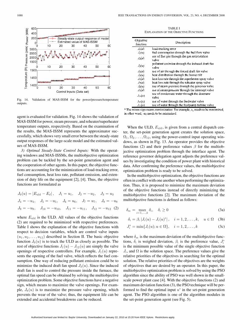
Fig. 14. Validation of MAS-ISSM for the power/pressure/temperatureoutputs.
agent is evaluated for validation. Fig. 14 shows the validation ofMAS-ISSM for power, steam pressure, and reheater/superheatertemperature outputs, respectively. Based on the examination ofthe results, the MAS-ISSM represents the approximator suc-cessfully, which shows very small error between the steady-stateoutput responses of the large-scale model and the estimated val-ues of MAS-ISSM.
3) Optimal Steady-State Control Inputs: With the operat-ing windows and MAS-ISSMs, the multiobjective optimizationproblem can be tackled by the set-point generation agent andthe cooperation of other agents. In this paper, the objective func-tions are accounting for the minimization of load-tracking error,fuel consumption, heat loss rate, pollutant emission, and exten-sion of duty life on the equipment [2], [4]. Thus, the objectivefunctions are formulated as
J0(u) = |Euld − Ed | , J1 = u1 , J2 = −u2 , J3 = u3
J4 = −u4 , J5 = −u5 , J6 = u6 , J7 = u7 , J8 = −u8
J9 = −u9 , J10 = −u10 , J11 = −u11 , J12 = −u12 (2)
where Euld is the ULD. All values of the objective functions(2) are required to be minimized with respective preferences.Table I shows the explanation of the objective functions withrespect to decision variables, which are control valve inputs(u1 , u2 , . . . , u12) described in Section II. The basic objectivefunction J0(u) is to track the ULD as closely as possible. Therest of objective functions J1(u) − J12(u) are simply the valveopenings of respective controllers. For example, J1(u) repre-sents the opening of the fuel valve, which reflects the fuel con-sumption. One way of reducing pollutant emission could be tominimize the induced draft fan speed J3(u). Since the induceddraft fan is used to control the pressure inside the furnace, theoptimal fan speed can be obtained by solving the multiobjectiveoptimization problem. Some objective functions have a negativesign, which means to maximize the valve openings. For exam-ple, J8(u) is to maximize the pressure valve opening, whichprevents the wear of the valve; thus, the equipment life can beextended and accidental breakdowns can be reduced.
TABLE IEXPLANATION OF THE OBJECTIVE FUNCTIONS
When the ULD, Euld , is given from a central dispatch cen-ter, the set-point generation agent creates the solution space,Ω1 ,Ω2 , . . . ,Ω12 , using the power-control input operating win-dows, as shown in Fig. 13. An operator provides the objectivefunctions (2) and their preference values β for the multiob-jective optimization problem through the interface agent. Thereference governor delegation agent adjusts the preference val-ues by investigating the condition of power plant with historicaldata. After confirming the preference values, the multiobjectiveoptimization problem is ready to be solved.
In the multiobjective optimization, the objective functions areoften in conflict with one another when performing the optimiza-tion. Thus, it is proposed to minimize the maximum deviationof the objective functions instead of directly minimizing themultiobjective functions [2]. The maximum deviation of themultiobjective functions is defined as follows:
δm = maxi=1,...,k
δi , δi ≥ 0 (3a)
δi = βi |Ji(u) − Ji(u)∗| , i = 1, 2, . . . , k, u ∈ Ω (3b)
J∗i = minJi(u);u ∈ Ω, i = 1, 2, . . . , k (3c)
where δm is the maximum deviation of the multiobjective func-tions, δi is weighed deviation, βi is the preference value, J∗
i
is the minimum possible value of the single objective functionJi , and Ω is the solution space. The preference values give therelative priorities of the objectives in searching for the optimalsolution. The relative priorities of the objectives are the weightsof objectives that are desired by an operator. In this paper, themultiobjective optimization problem is solved by using the PSOalgorithm since the ability of PSO was well shown in the small-scale power plant case [4]. With the objective functions (2) andmaximum deviation function (3), the PSO technique will be per-formed to find the optimal input u∗ in the set-point generationagent. The PSO algorithm is one of the algorithm modules inthe set-point generation agent (see Fig. 5).
Authorized licensed use limited to: Baylor University. Downloaded on January 22, 2010 at 15:20 from IEEE Xplore. Restrictions apply.

HEO AND LEE: MAS-IRG FOR MULTIOBJECTIVE OPTIMAL POWER PLANT OPERATION 1089
Fig. 15. Concept of modification of a search point by PSO.
4) Overview of the Basic PSO: Basically, the PSO was de-veloped through simulation of birds flocking in 2-D space [8].The position of each bird (called particle) is represented by apoint in the X–Y coordinates and also the velocity is similarlydefined. Bird flocking is assumed to optimize a certain objectivefunction. Each particle knows its best value so far (pbest) and itscurrent position. This information is an analogy of the personalexperience of a particle. Moreover, each particle knows the bestvalue so far in the group (gbest) among pbests of all particles.This information is an analogy of a particle knowing how otherparticles around it have performed. Each particle tries to modifyits position using the concept of velocity. The velocity of eachparticle can be updated by the following equation:
vk+1i = wvk
i + c1 rand1 × (pbesti − ski )
+ c2 rand2 × (gbest − ski ) (4)
where vki is velocity of particle i at iteration k, w is weighting
function, c1 and c2 are weighting factors, rand1 and rand2 arerandom numbers between 0 and 1, sk
i is current position of par-ticle i at iteration k, pbesti is the pbest of particle i, and gbest isthe best value so far in the group among the pbests of all particles.The first term in the right-hand side of (4) is for diversificationin the search procedure, which keeps on trying to explore newareas. The second and third terms are for intensification in thesearch procedure. They help in moving toward the pbests and/orgbest [12]. The method has a well-balanced mechanism to uti-lize diversification and intensification efficiently in the searchprocedure. The following weighting function is usually utilizedin (4):
w = wmax − wmax − wmin
itermax× iter (5)
where wmax is the initial weight, wmin is the final weight,itermax is the maximum iteration number, and iter is the cur-rent iteration number. Using the previous equations, a certainvelocity, which gradually brings the particles close to pbest andgbest, can be calculated. The current position (search point inthe solution space) can be modified by the following equation:
sk+1i = sk
i + vk+1i . (6)
The model using (4) is called the Gbest model. The modelusing (5) in (4) is called the inertia weights approach (IWA).Fig. 15 shows the concept of modification of a search point bythe PSO. The PSO is applied by replacing the control input ui
with the particle ski in the multiobjective optimization problem
(3).
Fig. 16. Total flow chart of PSO in the MAS-IRG.
5) Implementation of PSO in MAS-IRG: The PSO algorithmis applied to solve the multiobjective optimization problem inthe MAS-IRG. Fig. 16 shows the flow chart of the PSO indesigning the MAS-IRG with the set-point generation agent (cf.Fig. 5). The role of the set-point generation agent is to solve themultiobjective optimization problem in the MAS-IRG. In orderto solve the conflicted operating requirements in (2), the set-point generation agent utilizes the maximum deviation function(3) with the basic PSO. The PSO searches for the best inputvalues to minimize the maximum deviation of multiobjectivefunctions.
Initialization: The first step of the PSO for the MAS-IRG israndom generation of the particles in the solution space, whichis the feasible input regions, Ω1 ,Ω2 , . . . ,Ω12 generated with thegiven ULD by using power-input operating window, as shown inFig. 13. The particles represent the search points in the solutionspace, which are expressed by controls u1 , u2 , . . . , u12 . More-over, the initial velocities are also generated randomly within thesame space. Whenever the ULD is changed, the initial particlesand velocities are created in the solution space corresponding tothe given ULD. To find the PSO parameter values, experimentsare performed by trial and error, by testing the convergencerate with many different parameter values of c1 , c2 , Wmax , andWmin . Fig. 17 shows the examples of evaluation for the con-vergence rate by changing the parameter values. In order tospeed up the search for an optimal solution, c1 and c2 are setto 2, wmax = 0.8, and wmin = 0.3. The number of particles is40 and the number of iterations is 130. If the values of param-eters for PSO are not properly given, the convergence occurstoo early and the PSO cannot provide the optimal solution. Theinitial pbests are equal to the current search points and gbest isfound by comparing the pbests among the particles.
Authorized licensed use limited to: Baylor University. Downloaded on January 22, 2010 at 15:20 from IEEE Xplore. Restrictions apply.

1090 IEEE TRANSACTIONS ON ENERGY CONVERSION, VOL. 23, NO. 4, DECEMBER 2008
Fig. 17. Evaluation of convergence rate with different values of parameters.
Evaluation: The evaluation of search point for each parti-cle is performed using maximum deviation function (3) in thePSO algorithm. During the search for the solution, one of theMAS-ISSMs Ed = φ1 (u1 , u2 , . . . , u12) is utilized to evaluatethe load-tracking error. While searching for the optimal solution,the maximum deviation is getting smaller through the iterationof the control valve inputs u1 , u2 , . . . , u12 .
Modification: The modification of current search point is per-formed by (4)–(6) in every iteration.
6) Calculation of Set Points: After finding the optimal so-lution u∗
1 , u∗2 , . . . , u
∗12 , using the PSO, the MAS-ISSMs are ap-
plied to map the optimal solution into demand power (Ed ),steam pressure (Pd ), reheater temperature (RTd ), and super-heater temperatures (STd ) using (1). The set-point schedulerblock (see Fig. 10) processes the task under the observation ofthe set-point generation agent.
V. SIMULATION RESULTS
In the following, the results of the MAS-IRG will be shownand the analysis of time response will be discussed. Simulationsdeal with three different cases.
Case 1: Minimize J0(u) only.Case 2: Minimize J0(u), J1(u), J2(u).Case 3: Minimize J0(u), J1(u), J2(u), . . . , J12(u).The objective functions are given in (2) and a vector of pref-
erence values is given by an operator. Fig. 18 shows a ULD thatresembles a typical load cycle. It has different rising and fallingslopes and different levels of constant powers. With the givenULD, the solution space is obtained using the power-input op-erating windows (see Fig. 13). Fig. 19 shows the solution space(Ω1 ,Ω2 , . . . ,Ω12) for the given ULD. The gaps between up-per and lower limits are the solution space for the optimizationprocess. Next step is to perform the PSO for the multiobjectiveoptimization with predefined objective functions and preferencevalues. Finally, the power, pressure, and temperature set pointsare obtained by set-point scheduler (1) as shown in Figs. 20–22,respectively. The demand power set point (Ed ) is almost thesame for all cases as the ULD (see Fig. 18). The demand pres-sure (Pd ) and temperature set points (RTd , STd ) mapped for
Fig. 18. ULD.
Fig. 19. Solution space (Ω1 , Ω2 , . . . , Ω12 ) for the given ULD.
different number of objective functions are shown in Figs. 21and 22. It is interesting to note that while the demand powerset-point profile is almost the same for all cases, the demandpressure set-point profiles differ significantly from case to case.
Authorized licensed use limited to: Baylor University. Downloaded on January 22, 2010 at 15:20 from IEEE Xplore. Restrictions apply.

HEO AND LEE: MAS-IRG FOR MULTIOBJECTIVE OPTIMAL POWER PLANT OPERATION 1091
TABLE IICOMPARISON THE OBJECTIVE VALUES AMONG THE CASES
Fig. 20. Demand power set-point trajectories.
Fig. 21. Demand pressure set-point trajectories.
This is because the power–pressure operating window is quitelarge and the same amount of power can be produced on a widerange of pressure, as shown in Fig. 12. Moreover, the differ-ent temperatures of reheater/superheater can produce the sameamount of power. As additional objective functions are addedin the optimization, the plant is operating more conservativelyin lower pressure and temperatures. The demand powers (Ed )are almost the same as the ULD, as shown in Fig 18; however,the conflicting requirements cause slight difference between thedemand power and the ULD. Thus, all simulation results showthat the MAS-IRG can perform well in the multiobjective opti-mization problem and also in the online implementation sincethe pressure and temperatures set points need to be updated onlywhen the ULD is changed during the load cycle. Moreover, dis-tributed computing, which is the advantage of the MAS, reduces
Fig. 22. Demand reheater/superheater temperature set-point trajectories.
the computing time for online implementation. The goal of theMAS-IRG is to design the optimal set points when there areseveral conflicting objectives. The design is based on the sim-ulation of the power plant model, which does not depend upondata; hence, the usual problem of noise is not of concern. Inpractical implementation, this design can be done offline andthe set points can be stored in a lookup table. In case whenthe ULD is given in advance, which is usually the case, the setpoints can also be computed in advance offline for real-timeapplication.
VI. CONCLUSION
A new concept of the IRG based on the MAS is presented formultiobjective optimal power plant operation. In order to dealwith the difficulty of handling a large-scale system, architec-ture of a single agent and an organization of MAS are designedas basis for the IRG. The proposed MAS reduces the couplingproblems of subsystems by intelligent and asynchronous com-putation. The optimal mappings between the varying ULD andthe power, steam pressure, and reheater/superheater tempera-ture set points are realized in an online implementation with thehelp of MAS. The MAS-IRG provides the optimal set pointsfor the feedforward and feedback control loops in coordinatedcontrol system by the cooperation of MAS-ISSM. The MAS-ISSM is continuously adapted to the current condition of thepower plant with the cooperation of agents. As one of algo-rithm modules, PSO is well suited for finding optimal solutionin the multiobjective optimization problem under a diversityof operating scenarios. Table II compares the average perfor-mance of the PSO technique while increasing the number of
Authorized licensed use limited to: Baylor University. Downloaded on January 22, 2010 at 15:20 from IEEE Xplore. Restrictions apply.

1092 IEEE TRANSACTIONS ON ENERGY CONVERSION, VOL. 23, NO. 4, DECEMBER 2008
objective functions. The case I minimizes only J0 that is indi-cated with a highlight box. Similarly, the other highlight boxesshows which objectives are considered for minimization in thecases II and III. Due to the confliction of requirements, the per-formance values of objective functions are changed while in-creasing the objective functions. Therefore, the PSO and MASare efficient methodologies to design the IC system for a com-plex large-scale power plant.
REFERENCES
[1] H. C. Pietrobom and K. H. Kienitz, “Using surrogates to reduce timeexpenditure for optimization in systems and control,” in Proc. 40th IEEEConf. Decis. Control, Orlando, FL, 2001, vol. 4, pp. 3178–3183.
[2] R. Garduno-Ramirez and K. Y. Lee, “Multiobjective optimal power plantoperation through coordinate control with pressure set point schedul-ing,” IEEE Trans. Energy Convers., vol. 16, no. 2, pp. 115–122, Jun.2001.
[3] J. Chang, K. Y. Lee, and R. Garduno-Ramirez, “Optimal task decompo-sition agents of the multiagent power plant control system,” presented atthe 2003 Int. Conf. Intell. Syst. Appl. Power Syst., Lemnos, Greece, 2003,Paper CD ISAP03-085.
[4] J. S. Heo, K. Y. Lee, and R. Garduno-Ramirez, “Multiobjective control ofpower plant using particle swarm optimization techniques,” IEEE Trans.Energy Convers., vol. 21, no. 2, pp. 552–561, Jun. 2006.
[5] J. S. Heo, K. Y. Lee, and R. Garduno-Ramirez, “Multiobjective optimalpower plant operation using particle swarm optimization technique,” pre-sented at the IFAC Congr., Prague, Czech Republic, 2005, Paper 04833,Tu-M06-TO/4.
[6] K. Y. Lee and M. A. El-Sharkawi, Eds., Tutorial on Modern HeuristicOptimization Techniques With Applications to Power Systems. Piscat-away, NJ: IEEE Power Engineering Society, 2002 (IEEE Catalog Number02TP160).
[7] J. Kennedy and R. Eberhart, “Particle swarm optimization,” in Proc. 1995IEEE Int. Conf. Neural Netw., vol. 4, pp. 1942–1948.
[8] C. Reynolds, “Flocks, herds, and schools: A distributed behavioral model,”Comput. Graph., vol. 21, no. 4, pp. 25–34, 1987.
[9] P. Angeline, “Using selection to improve particle swarm optimization,” inProc. 1998 IEEE Int. Conf. Evol. Comput., pp. 84–89.
[10] V. Miranda and N. Fonseca, “EPSO-evolutionary particle swarm opti-mization, a new algorithm with applications in power systems,” in Proc.2002 IEEE Transmiss. Distrib. Conf. Exhib., vol. 2, pp. 6–10.
[11] M. Clerc, “The swarm and the queen: Towards a deterministic and adap-tive particle swarm optimization,” in Proc. 1999 IEEE Int. Conf. Evol.Comput., pp. 1951–1957.
[12] R. Eberhart and Y. Shi, “Comparing inertia weights and constriction fac-tors in particle swarm optimization,” in Proc. 2000 Congr. Evol. Comput.,pp. 84–88.
[13] J.-B. Park, K.-S. Lee, J.-R. Shin, and K. Y. Lee, “A particle swarm opti-mization for economic dispatch with non-smooth cost functions,” IEEETrans. Power Syst., vol. 20, no. 1, pp. 34–42, Feb. 2005.
[14] D. Angeli and E. Mosca, “Command governors for constrained nonlinearsystems,” IEEE Trans. Autom. Control, vol. 44, no. 4, pp. 816–820, Apr.1999.
[15] E. Gilbert and I. Kolmanovsky, “Fast reference governors for systemswith state and control constraints and disturbance inputs,” Int. J. RobustNonlinear Control, vol. 9, no. 15, pp. 1117–1141, 1999.
[16] A. Ordys, M. Johnson, R. Katebi, and M. Grimble, Modelling and Sim-ulation of Power Generation Plants. London, U.K.: Springer-Verlag,1994.
[17] P. B. Usoro, “Modeling and simulation of a drum-turbine power plantunder emergency state control,” M.S. thesis, Massachusetts Inst. Technol.,Cambridge, 1977.
[18] S. J. Al-Nasurs, “Simulation of a fossil-fuel power plant unit in matlabenvironment,” M.S. thesis, Dept. Electr. Eng., The Pennsylvania StateUniv., University Park, 2001.
[19] J. P. McDonald, H. G. Kwatny, and J. H. Spare, “A non-linear model forreheat boiler-turbine generator systems; part I—General description andevaluation,” in Proc. 12th Joint Autom. Control Conf., 1971, pp. 219–226.
[20] H. G. Kwatny, J. P. McDonald, and J. H. Spare, “A non-linear model forreheat boiler-turbine generator systems; part II—Development,” in Proc.12th Joint Autom. Control Conf., 1971, pp. 227–236.
[21] W. Junpu, C. Hao, X. Yang, and L. Shuhui, “An architecture of agent-basedintelligent control systems,” in Proc. 3rd World Congr. Intell. ControlAutom., 2000, pp. 404–407.
[22] T. Wittig, N. R. Jennings, and E. H. Mamdani, “ARCHON: Frameworkfor intelligent co-operation,” IEEE Trans. Intell. Syst. Eng., vol. 3, no. 3,pp. 168–179, Autumn 1994.
[23] J. Kosakaya, A. Kobayashi, and K. Yamaoka, “Cooperative multi-agent-based control technology for supervisory control and data-acquisition sys-tems,” in Proc. Emerging Technol. Factory Autom. Conf., 2003, pp. 19–26.
[24] J. Jung and C.-H. Liu, “Multi-agent system technologies and an applica-tion for power system vulnerability,” in Proc. IEEE Power Eng. Soc. Gen-eral Meeting, Denver, CO, 2004, vol. 1, pp. 61–64, Paper PESGM2004-000975.
[25] J. A. Hossack, J. Menal, S. D. J. McArthur, and J. R. McDonald, “Amultiagent architecture for protection engineering diagnostic assistance,”IEEE Trans. Power Syst., vol. 18, no. 2, pp. 639–647, May 2003.
[26] L. Padgham and M. Winikoff, Developing Intelligent Agent Systems.Hoboken, NJ: Wiley, 2004.
[27] M. Wooldridge, An Introduction To Multiagent Systems. Chichester,U.K.: Wiley, 2002.
[28] J. S. Heo and K. Y. Lee, “Multi-agent system-based intelligent control sys-tem for a power plant,” in Proc. IEEE Power Eng. Soc. General Meeting,San Francisco, CA, 2005, vol. 2, pp. 1050–1055, Paper CD PESGM2005-000858.
[29] J. S. Heo and K. Y. Lee, “Multi-agent system-based intelligent steady-statemodel for a power plant,” in Proc. 13th Int. Conf. Intell. Syst. Appl. PowerSyst., Arlington, VA, 2005, pp. 419–424.
[30] J. S. Heo and K. Y. Lee, “A multi-agent system-based intelligent iden-tification system for control and fault-diagnosis for a large-scale powerplant,” presented at the IEEE Power Eng. Soc. General Meeting, Montreal,QC, Canada, 2006.
[31] H. C. Gery, “The evolution of coordinated control,” Inst. Soc. Amer. PowerSymp., St. Petersburg, FL, 1988, pp. 109–112, paper no. 88-0417.
[32] R. Fray, “Compact simulators for fossil-fueled power plants,” IEEESpectr., vol. 32, no. 2, pp. 46–51, Feb. 1995.
Jin S. Heo received the B.S. and M.S. degrees in elec-tronics engineering from Inje University, Gimhae,Korea, in 1999 and 2001, respectively, and the Ph.D.degree in electrical engineering from the Pennsylva-nia State University, University Park, in 2006.
His current research interests include multiobjec-tive optimization in control system, intelligent dis-tributed control, multiagent system, modeling andcontrol of power plants, and real-time embedded sys-tem.
Kwang Y. Lee (S’70–M’72–SM’86–F’01–LF’08)received the B.S. degree in electrical engineeringfrom Seoul National University, Seoul, Korea, in1964, the M.S. degree in electrical engineering fromNorth Dakota State University, Fargo, in 1968, andthe Ph.D. degree in system science from MichiganState University, East Lansing, in 1971.
He has been with Michigan State University,Oregon State University, and the University ofHouston. He has also been with The PennsylvaniaState University, University Park and Baylor Univer-
sity, where he is currently a Professor and Chair of electrical and computerengineering and the Director of Power Systems Control Laboratory. His currentresearch interests include power system control, operation, planning, and intel-ligent system applications to power systems.
Dr. Lee is an Associate Editor of the IEEE TRANSACTIONS ON NEURAL NET-WORKS and the Editor of the IEEE TRANSACTIONS ON ENERGY CONVERSION.He is also a Registered Professional Engineer.
Authorized licensed use limited to: Baylor University. Downloaded on January 22, 2010 at 15:20 from IEEE Xplore. Restrictions apply.


